CN102565475A - Electricity stealing prevention device for electric energy meter - Google Patents
Electricity stealing prevention device for electric energy meterDownload PDFInfo
- Publication number
- CN102565475A CN102565475ACN2012100145660ACN201210014566ACN102565475ACN 102565475 ACN102565475 ACN 102565475ACN 2012100145660 ACN2012100145660 ACN 2012100145660ACN 201210014566 ACN201210014566 ACN 201210014566ACN 102565475 ACN102565475 ACN 102565475A
- Authority
- CN
- China
- Prior art keywords
- energy meter
- pole
- binding post
- contacts
- sheet
- Prior art date
- Legal status (The legal status is an assumption and is not a legal conclusion. Google has not performed a legal analysis and makes no representation as to the accuracy of the status listed.)
- Granted
Links
Images


Landscapes
- Switches That Are Operated By Magnetic Or Electric Fields (AREA)
- Burglar Alarm Systems (AREA)
Abstract
Translated fromChinese
Description
Translated fromChinese技术领域technical field
本发明涉及一种电能表,特别是一种能有效地阻止窃电行为的电能表防窃电装置。The present invention relates to an electric energy meter, in particular to an electric energy meter anti-stealing device that can effectively prevent electricity theft.
the
背景技术Background technique
目前,一些不法分子钻电力安装、管理上的漏洞,故意改变电能表计量回路的相位、电压、电流的接线方式,改变电能表本身的结构、性能,大肆进行窃电,从而使供电部门和国家资源、财产造成重大损失。At present, some criminals take advantage of loopholes in power installation and management, deliberately change the phase, voltage, and current wiring methods of the metering circuit of the electric energy meter, change the structure and performance of the electric energy meter itself, and wantonly steal electricity, thus making the power supply department and the country Resources and property caused heavy losses.
发明内容Contents of the invention
本发明的目的在于克服现有技术的不足之处,而提供一种能防止被窃电的电能表防窃电装置。The purpose of the present invention is to overcome the disadvantages of the prior art, and provide an anti-stealing device for electric energy meters that can prevent electricity theft.
一种电能表防窃电装置,其特征在于:包括有磁敏开关、磁片、滑动绝缘极柱、起止柱、密码锁、复位弹簧及接线柱,磁片设置于磁敏开关两触点的附近,并可相对磁敏开关做远离或靠近的往复直线运动,磁片与滑动绝缘极柱相连,滑动绝缘极柱通地预紧力弹簧插于接线柱内并可相对接线柱做往复直线运动,所述的预紧力弹簧将与滑动绝缘极柱相连的磁片压在能让磁敏开关两接触点吸合的位置处,在滑动绝缘极柱的一侧设置有一凹槽,由密码锁控制的起止柱被压紧的设置于滑动绝缘极柱的凹槽侧并在预紧力弹簧处于释放状态时滑动绝缘极柱的运行方向上,所述的磁敏开关的两触点分别与接线柱导电片的两触点相连,所述的导电片中段为由绝缘材料构成形成两端导电中间不导电的结构。An electric energy meter anti-stealing device is characterized in that it includes a magnetic sensitive switch, a magnetic sheet, a sliding insulating pole, a start and stop column, a combination lock, a return spring and a terminal, and the magnetic sheet is arranged on the two contacts of the magnetic sensitive switch. Nearby, and can do reciprocating linear motion away from or close to the magnetic sensitive switch. The magnetic sheet is connected with the sliding insulating pole, and the sliding insulating pole is inserted into the terminal through the pre-tightening force spring and can perform reciprocating linear motion relative to the terminal. , the pre-tightening force spring presses the magnetic sheet connected to the sliding insulating pole at the position where the two contact points of the magnetic sensitive switch can be pulled together, and a groove is arranged on one side of the sliding insulating pole, and the combination lock The start-stop column of the control is pressed and arranged on the groove side of the sliding insulating pole, and in the running direction of the sliding insulating pole when the pre-tightening force spring is in the released state, the two contacts of the magnetic sensitive switch are respectively connected to the wiring The two contacts of the column conductive sheet are connected, and the middle section of the conductive sheet is made of insulating material to form a structure in which both ends are conductive and the middle is non-conductive.
这种结构的电能表防窃电装置,由于磁敏开关是一种特殊开关,它的两个触点由特殊材料制成,被封装在真空的玻璃管里。只要用磁铁接近它,两个触点就会吸合在一起,使电路导通。因此本发明利用磁敏开关的这一特点,将磁敏开关引入到防窃电装置中,并在磁敏开关附近设置磁片,利用磁片来控制磁敏开关的吸与合,而磁片又通过简单巧妙的结构,即将磁片与滑动绝缘极柱相连,将滑动绝缘极柱通过预紧弹簧压在接线柱中,一旦有人窃电将输入电源火线从电表接线柱拨出,这时滑动绝缘极柱由于预紧弹簧的作用立即动作,使绝缘极柱带动磁片远离磁敏开关,从而使磁敏开关的两触点分离,使得输入端火线被断开,从而达到切断输入火线的功能,在绝缘极柱动作的同时,起止柱在绝缘极柱的凹槽与其相吻合的那一刻滑入凹槽内,由于密码锁的作用,起止柱将滑动绝缘极柱锁死,使之无法复位,从而实现切断供电,以起到防窃电的目的。如需恢复供电,必须有供电部门人员将设置好的密码打开后,使得滑动绝缘极柱复位并将电源火线接入接线柱从而使滑动绝缘极将磁片顶起使其靠近磁敏开关,使接点动作闭合恢复正常工作。The electric energy meter anti-stealing device of this structure, because the magnetic sensitive switch is a kind of special switch, its two contacts are made of special materials, are encapsulated in the glass tube of vacuum. Just approach it with a magnet, and the two contacts will snap together, making the circuit conductive. Therefore the present invention utilizes this feature of the magnetic sensitive switch, the magnetic sensitive switch is introduced in the anti-theft device, and the magnetic sheet is set near the magnetic sensitive switch, utilizes the magnetic sheet to control the suction and closing of the magnetic sensitive switch, and the magnetic sheet And through a simple and ingenious structure, the magnetic piece is connected to the sliding insulating pole, and the sliding insulating pole is pressed into the terminal through the pre-tightened spring. The insulated pole moves immediately due to the action of the pre-tightened spring, so that the insulated pole drives the magnetic piece away from the magnetic sensitive switch, so that the two contacts of the magnetic sensitive switch are separated, and the live wire of the input terminal is disconnected, thereby achieving the function of cutting off the input live wire , while the insulating pole is moving, the start-stop column slides into the groove at the moment when the groove of the insulating pole matches with it. Due to the function of the code lock, the start-stop column locks the sliding insulating pole so that it cannot be reset , so as to cut off the power supply, so as to prevent electricity theft. If the power supply needs to be restored, the personnel of the power supply department must open the set password, reset the sliding insulating pole and connect the live wire of the power supply to the terminal, so that the sliding insulating pole can lift the magnetic piece and make it close to the magnetic switch, so that The contact action is closed to resume normal operation.
所述的磁敏开关为干簧管。The magnetic sensitive switch is a dry reed switch.
所述的磁片为钕铁硼磁片。其具有体积小、重量轻的特点,是一种人造的永久磁铁,是迄今为止具有最强磁力的永久磁铁。The magnetic sheet is an NdFeB magnetic sheet. It has the characteristics of small size and light weight. It is an artificial permanent magnet and the permanent magnet with the strongest magnetic force so far.
所述的接线柱或可直接利用原电能表的接线柱对其进行改装,即将原火线接线柱导电金属片一分为二,在中间用胶木绝缘材料分隔。当然也可以直接用新的接线柱替换原有的接线柱,新的接线柱为其导电金属片为上下两段为导电的金属片,中段为绝缘材料构成的绝缘段。Said binding post may directly use the binding post of the original electric energy meter to refit it, that is, the conductive metal sheet of the original live wire binding post is divided into two, and separated by bakelite insulating material in the middle. Certainly also can directly replace original binding post with new binding post, and new binding post is that its conductive metal sheet is that the upper and lower sections are conductive metal sheets, and the middle section is an insulating section made of insulating material.
所述的密码锁为三位数字的密码锁。The combination lock is a three-digit combination lock.
综上所述的,本发明相比现有技术如下优点:In summary, compared with the prior art, the present invention has the following advantages:
本电能表防窃电装置,结构设计合理,使用方便、安全、可靠,一旦有人窃电,防窃电模块立即工作切断输入电源,切断电源回路,克服了长期以来未能解决的难题,有效地阻止了窃电行为。其可以直接在新的电能表中加入本装置,也可以对已有的旧的电能表进行改装,改装也非常的简单方便,只需对原电能表接线柱的导电片进行改装即可,因此非常的适用。The anti-stealing device of the electric energy meter has reasonable structure design, convenient use, safety and reliability. Once someone steals electricity, the anti-stealing module immediately works to cut off the input power supply and cut off the power circuit, which overcomes the long-standing unsolved problems and effectively Electricity theft is prevented. It can directly add this device to a new electric energy meter, or modify an existing old electric energy meter. The modification is also very simple and convenient. It only needs to modify the conductive sheet of the original electric energy meter terminal, so Very applicable.
the
附图说明Description of drawings
图1是防窃电电能表原理图。Figure 1 is the schematic diagram of the anti-theft electric energy meter.
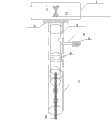
图2是防窃电装置结构图。Fig. 2 is a structural diagram of the anti-stealing device.
图3是改造后的导电片图。Figure 3 is a diagram of the modified conductive sheet.
图4是干簧管接线示意图。Figure 4 is a schematic diagram of reed switch wiring.
图5是火线接线柱导电片被拔出后的电能表防窃电装置示意图。Fig. 5 is a schematic diagram of the electric energy meter anti-stealing device after the conductive piece of the live wire terminal is pulled out.
图6是本电能表防窃电装置处于正常接电输入状态示意图。Fig. 6 is a schematic diagram of the electric energy meter anti-stealing device in a normal power input state.
标号说明:1干簧管 2 钕铁硼磁片 3 滑动绝缘极柱 4 起止柱 5 三位数字密码锁 6 预紧弹簧 7 接线柱 8 火线接入导线 9 导电片 10 胶木绝缘体。Explanation of symbols: 1
具体实施方式Detailed ways
下面结合实施例对本发明进行更详细的描述。The present invention will be described in more detail below in conjunction with examples.
实施例1 Example 1
一种如图1-6所示的电能表防窃电装置,包括一个16A干簧管1、一块钕铁硼磁片2、滑动绝缘极柱3、起止柱4、三位数字密码锁5、预紧弹簧6及接线柱7共同组成一个电能表防窃电装置。钕铁硼磁片设置于干簧管两触点的附近,并可相对干簧管做远离或靠近的往复直线运动,磁片与滑动绝缘极柱相连,滑动绝缘极柱通地预紧力弹簧插于接线柱内并可相对接线柱做往复直线运动,所述的预紧力弹簧将与滑动绝缘极柱相连的磁片压在能让干簧管两接触点吸合的位置处,在滑动绝缘极柱的一侧设置有一凹槽,由密码锁控制的起止柱被压紧的设置于滑动绝缘极柱的凹槽侧并在预紧力弹簧处于释放状态时滑动绝缘极柱的运行方向上,所述的干簧管的两触点分别与接线柱导电片9的两触点相连,所述的导电片中段为由绝缘材料—胶木绝缘体10构成形成两端导电中间不导电的结构。An electric energy meter anti-stealing device as shown in Figure 1-6, comprising a
在正常的情况下,干簧管是一组闭合的接点,接点1、2静态闭合,正常供电,即导线8顶住滑动绝缘极柱3,使钕铁硼磁片2接近16A干簧管1,干簧管接点1、2闭合,接通输入电路,使电能表处于正常工作状态。一旦有人窃电将输入电源火线从电表接线柱拔出,这时防窃电滑动绝缘极柱3由于预紧弹簧6的作用立即动作,起止柱4滑向槽内,使钕铁硼磁片2离开16A干簧管1,此时干簧管的静合接点1、2被拉开,将输入端火线断开,从而达到切断输入火线的功能。这时由于三位数字密码锁5的作用,起止柱4将滑动绝缘极柱3锁死,使之无法复位,实现切断供电,这样起到防窃电的目的。如需恢复供电,只有供电部门人员用设置好的密码打开后,滑动绝缘极柱3才能复位,并重新接入导线8,复位后的滑动绝缘极柱3将钕铁硼磁片2顶起,靠近16A干簧管1,使干簧管1动作,接点1、2闭合,闭合后恢复正常工作。Under normal circumstances, the reed switch is a group of closed contacts, the
本实施例未述部分与现有技术相同。The parts not described in this embodiment are the same as the prior art.
Claims (5)
Priority Applications (1)
| Application Number | Priority Date | Filing Date | Title |
|---|---|---|---|
| CN201210014566.0ACN102565475B (en) | 2012-01-18 | 2012-01-18 | Electricity stealing prevention device for electric energy meter |
Applications Claiming Priority (1)
| Application Number | Priority Date | Filing Date | Title |
|---|---|---|---|
| CN201210014566.0ACN102565475B (en) | 2012-01-18 | 2012-01-18 | Electricity stealing prevention device for electric energy meter |
Publications (2)
| Publication Number | Publication Date |
|---|---|
| CN102565475Atrue CN102565475A (en) | 2012-07-11 |
| CN102565475B CN102565475B (en) | 2014-06-18 |
Family
ID=46411423
Family Applications (1)
| Application Number | Title | Priority Date | Filing Date |
|---|---|---|---|
| CN201210014566.0AActiveCN102565475B (en) | 2012-01-18 | 2012-01-18 | Electricity stealing prevention device for electric energy meter |
Country Status (1)
| Country | Link |
|---|---|
| CN (1) | CN102565475B (en) |
Cited By (2)
| Publication number | Priority date | Publication date | Assignee | Title |
|---|---|---|---|---|
| CN103954815A (en)* | 2014-04-30 | 2014-07-30 | 国网上海市电力公司 | Electricity larceny prevention check main machine |
| CN110672896A (en)* | 2019-09-30 | 2020-01-10 | 国网河北省电力有限公司沧州供电分公司 | Electric meter box electricity stealing prevention system under ubiquitous internet |
Citations (6)
| Publication number | Priority date | Publication date | Assignee | Title |
|---|---|---|---|---|
| DE4136095C1 (en)* | 1991-11-02 | 1992-11-26 | Otto 6000 Frankfurt De Kittlinger | Motor vehicle anti-theft lock - has connection cables between handle lock and bonnet lock via electromagnet |
| WO2003065055A2 (en)* | 2002-01-31 | 2003-08-07 | Iskraemeco, Merjenje In Upravljanje Energije, D.D. | Magnetic field detection system for an electricity meter |
| CN201173941Y (en)* | 2008-02-04 | 2008-12-31 | 福建省福州电业局 | Anti-stealing electronic energy meter |
| CN201707364U (en)* | 2010-03-31 | 2011-01-12 | 贺凤义 | Intelligent electricity stealing prevention electronic energy meter device |
| CN201747146U (en)* | 2010-07-14 | 2011-02-16 | 北京平开智能电气有限公司 | Uninterrupted anti-theft electric program-control lock used for electric power metering box |
| CN202548173U (en)* | 2012-01-18 | 2012-11-21 | 福建省电力有限公司三明电业局 | Electricity-larceny-prevention device of electric energy meter |
- 2012
- 2012-01-18CNCN201210014566.0Apatent/CN102565475B/enactiveActive
Patent Citations (6)
| Publication number | Priority date | Publication date | Assignee | Title |
|---|---|---|---|---|
| DE4136095C1 (en)* | 1991-11-02 | 1992-11-26 | Otto 6000 Frankfurt De Kittlinger | Motor vehicle anti-theft lock - has connection cables between handle lock and bonnet lock via electromagnet |
| WO2003065055A2 (en)* | 2002-01-31 | 2003-08-07 | Iskraemeco, Merjenje In Upravljanje Energije, D.D. | Magnetic field detection system for an electricity meter |
| CN201173941Y (en)* | 2008-02-04 | 2008-12-31 | 福建省福州电业局 | Anti-stealing electronic energy meter |
| CN201707364U (en)* | 2010-03-31 | 2011-01-12 | 贺凤义 | Intelligent electricity stealing prevention electronic energy meter device |
| CN201747146U (en)* | 2010-07-14 | 2011-02-16 | 北京平开智能电气有限公司 | Uninterrupted anti-theft electric program-control lock used for electric power metering box |
| CN202548173U (en)* | 2012-01-18 | 2012-11-21 | 福建省电力有限公司三明电业局 | Electricity-larceny-prevention device of electric energy meter |
Cited By (2)
| Publication number | Priority date | Publication date | Assignee | Title |
|---|---|---|---|---|
| CN103954815A (en)* | 2014-04-30 | 2014-07-30 | 国网上海市电力公司 | Electricity larceny prevention check main machine |
| CN110672896A (en)* | 2019-09-30 | 2020-01-10 | 国网河北省电力有限公司沧州供电分公司 | Electric meter box electricity stealing prevention system under ubiquitous internet |
Also Published As
| Publication number | Publication date |
|---|---|
| CN102565475B (en) | 2014-06-18 |
Similar Documents
| Publication | Publication Date | Title |
|---|---|---|
| CN203787366U (en) | Residual current circuit breaker | |
| CN202548173U (en) | Electricity-larceny-prevention device of electric energy meter | |
| CN102693884B (en) | Special molded case circuit breaker for prepayment electric energy meter | |
| CN103681124B (en) | Closed multipole circuit breaker | |
| CN102565475A (en) | Electricity stealing prevention device for electric energy meter | |
| CN205070179U (en) | Electric blocking device of electric power low -voltage switchgear | |
| CN201838521U (en) | Monopole non-arcing permanent magnet alternating current contactor | |
| CN204144168U (en) | Magneto many-contact relay | |
| CN103545910A (en) | Dual-power-supply control circuit | |
| CN208077925U (en) | Novel residual current circuit breaker | |
| CN102412463A (en) | Electric contact device | |
| CN202259098U (en) | Short circuit and short delay protection device of breaker | |
| CN203192723U (en) | Undervoltage release device for circuit breaker | |
| CN202363369U (en) | Solenoid switch capable of automatically switching-off at power outage | |
| CN201732705U (en) | Arc-less alternating-current relay device | |
| CN203481149U (en) | Relay | |
| CN204167205U (en) | Three-winding magnetic suck cut-offs A.C. contactor circuit | |
| CN204167204U (en) | Energy saving ac contactor circuit structure system | |
| CN204167210U (en) | A.C. contactor flash device | |
| CN202712770U (en) | Universal novel permanent magnetic anti-trip junction box | |
| CN203398047U (en) | Breaker | |
| CN201518301U (en) | Auxiliary signal switch for small circuit breaker and circuit breaker for equipment | |
| CN205645726U (en) | Moulded case circuit breaker operating device protection device | |
| CN204680631U (en) | A kind of shunt trip of circuit breaker | |
| CN104269294B (en) | Three-phase integratedization exchanges without arc electrical equipment |
Legal Events
| Date | Code | Title | Description |
|---|---|---|---|
| C06 | Publication | ||
| PB01 | Publication | ||
| C10 | Entry into substantive examination | ||
| SE01 | Entry into force of request for substantive examination | ||
| ASS | Succession or assignment of patent right | Owner name:STATE GRID CORPORATION OF CHINA Free format text:FORMER OWNER: FUJIAN PROVINCE ELETRIC POWER CO., LTD. SANMING POWER SUPPLY BUREAU Effective date:20121227 Owner name:FUJIAN ELECTRIC POWER CO., LTD. FUJIAN PROVINCE EL Free format text:FORMER OWNER: FUJIAN JIANNING POWER SUPPLY CO., LTD. Effective date:20121227 | |
| C41 | Transfer of patent application or patent right or utility model | ||
| COR | Change of bibliographic data | Free format text:CORRECT: ADDRESS; FROM: 365000 SANMING, FUJIAN PROVINCE TO: 100031 XICHENG, BEIJING | |
| TA01 | Transfer of patent application right | Effective date of registration:20121227 Address after:100031 Xicheng District West Chang'an Avenue, No. 86, Beijing Applicant after:State Grid Corporation of China Applicant after:Fujian Electric Power Co., Ltd. Applicant after:Sanming Electricity Bureau of Fujian Electric Power Co., Ltd. Applicant after:Fujian Jianning County Power Supply Co., Ltd. Address before:Fujian 365000 Sanming City province Meliet District listed Street No. 1032 Applicant before:Sanming Electricity Bureau of Fujian Electric Power Co., Ltd. Applicant before:Fujian Jianning County Power Supply Co., Ltd. | |
| C14 | Grant of patent or utility model | ||
| GR01 | Patent grant |