CN102556433B - Dual-clamp card puncher with single cylinder and single claw - Google Patents
Dual-clamp card puncher with single cylinder and single clawDownload PDFInfo
- Publication number
- CN102556433B CN102556433BCN201210013258.6ACN201210013258ACN102556433BCN 102556433 BCN102556433 BCN 102556433BCN 201210013258 ACN201210013258 ACN 201210013258ACN 102556433 BCN102556433 BCN 102556433B
- Authority
- CN
- China
- Prior art keywords
- card
- fixed
- monodactyle
- cylinder
- single cylinder
- Prior art date
- Legal status (The legal status is an assumption and is not a legal conclusion. Google has not performed a legal analysis and makes no representation as to the accuracy of the status listed.)
- Expired - Fee Related
Links
- 210000000078clawAnatomy0.000titleclaimsdescription12
- 238000012546transferMethods0.000claimsabstractdescription10
- 238000000034methodMethods0.000claimsabstractdescription5
- 230000008569processEffects0.000claimsabstractdescription4
- 230000007246mechanismEffects0.000claimsdescription15
- 239000000758substrateSubstances0.000claims4
- 238000007493shaping processMethods0.000claims1
- 238000004080punchingMethods0.000abstractdescription22
- 230000009471actionEffects0.000description2
- 238000010586diagramMethods0.000description2
- 230000000694effectsEffects0.000description2
- 238000013459approachMethods0.000description1
- 230000009286beneficial effectEffects0.000description1
- 230000007812deficiencyEffects0.000description1
- 239000003814drugSubstances0.000description1
- 229940079593drugDrugs0.000description1
- 230000009977dual effectEffects0.000description1
- 238000005265energy consumptionMethods0.000description1
- 239000002360explosiveSubstances0.000description1
- 235000013305foodNutrition0.000description1
- 238000012986modificationMethods0.000description1
- 230000004048modificationEffects0.000description1
- 238000003032molecular dockingMethods0.000description1
- 238000004806packaging method and processMethods0.000description1
- 235000013580sausagesNutrition0.000description1
Images


Classifications
- B—PERFORMING OPERATIONS; TRANSPORTING
- B65—CONVEYING; PACKING; STORING; HANDLING THIN OR FILAMENTARY MATERIAL
- B65B—MACHINES, APPARATUS OR DEVICES FOR, OR METHODS OF, PACKAGING ARTICLES OR MATERIALS; UNPACKING
- B65B51/00—Devices for, or methods of, sealing or securing package folds or closures; Devices for gathering or twisting wrappers, or necks of bags
- B65B51/04—Applying separate sealing or securing members, e.g. clips
- B65B51/05—Stapling
- A—HUMAN NECESSITIES
- A22—BUTCHERING; MEAT TREATMENT; PROCESSING POULTRY OR FISH
- A22C—PROCESSING MEAT, POULTRY, OR FISH
- A22C11/00—Sausage making ; Apparatus for handling or conveying sausage products during manufacture
- A22C11/12—Apparatus for tying sausage skins ; Clipping sausage skins
- A22C11/125—Apparatus for tying sausage skins ; Clipping sausage skins by clipping; Removal of clips
- Y—GENERAL TAGGING OF NEW TECHNOLOGICAL DEVELOPMENTS; GENERAL TAGGING OF CROSS-SECTIONAL TECHNOLOGIES SPANNING OVER SEVERAL SECTIONS OF THE IPC; TECHNICAL SUBJECTS COVERED BY FORMER USPC CROSS-REFERENCE ART COLLECTIONS [XRACs] AND DIGESTS
- Y10—TECHNICAL SUBJECTS COVERED BY FORMER USPC
- Y10T—TECHNICAL SUBJECTS COVERED BY FORMER US CLASSIFICATION
- Y10T29/00—Metal working
- Y10T29/53—Means to assemble or disassemble
- Y10T29/53709—Overedge assembling means
- Y10T29/53783—Clip applier
Landscapes
- Engineering & Computer Science (AREA)
- Life Sciences & Earth Sciences (AREA)
- Wood Science & Technology (AREA)
- Zoology (AREA)
- Food Science & Technology (AREA)
- Mechanical Engineering (AREA)
- Perforating, Stamping-Out Or Severing By Means Other Than Cutting (AREA)
- Making Paper Articles (AREA)
- Preliminary Treatment Of Fibers (AREA)
Abstract
Translated fromChineseDescription
Translated fromChinese技术领域technical field
本发明涉及乳化炸药、药卷和食品香肠及软包装行业技术领域,具体的说,本发明涉及单缸单爪气动双卡打卡机。The invention relates to the technical field of emulsified explosives, drug rolls, food sausages and soft packaging industries. Specifically, the invention relates to a single-cylinder, single-claw pneumatic double-card punching machine.
背景技术Background technique
US3783583公布了一种气动打卡机的专利,其采用多气缸驱动完成打卡。目前气动双卡打卡机的打卡速度一般在50次/分。通过电动可以提高打卡速度,这种打卡机通过转轴、连杆、杠杆、凸轮、拨叉、滑板、滑轨、摆动轴、裁断气缸等一系列较为复杂的机械原件依次来完成打卡,打卡速度可达130次/分。但这种打卡机空间尺寸大,重量达几百公斤。US3783583 has announced the patent of a kind of pneumatic card punching machine, and it adopts multi-cylinder drive to finish punching cards. At present, the punching speed of the pneumatic dual card punching machine is generally 50 times/min. The punching speed can be increased by electric power. This kind of punching machine completes punching through a series of relatively complex mechanical components such as rotating shafts, connecting rods, levers, cams, shift forks, slides, slide rails, swing shafts, and cutting cylinders. The punching speed can be increased. Up to 130 times/min. But this punch card machine has a large space size and weighs several hundred kilograms.
US4821485公布了一种单爪气动打卡机。该打卡机由送卡气缸两个、收拢气缸一个、打卡气缸一小一大联动工作、裁断气缸一个,大小共计六只气缸来共同完成打卡程序的,打卡速度约40次/分。但该打卡机结构复杂、能耗较高。US4821485 has announced a kind of single claw pneumatic punching machine. The card punching machine consists of two feeding cylinders, one retracting cylinder, one small and one large punching cylinder, one cutting cylinder, and a total of six cylinders of different sizes to complete the punching program. The punching speed is about 40 times/min. However, the punch card machine has a complex structure and high energy consumption.
针对现有技术存在的上述不足,提出本发明。The present invention is proposed aiming at the above-mentioned deficiencies existing in the prior art.
发明内容Contents of the invention
本发明的目的在于提供了一种单缸单爪气动双卡打卡机。The object of the present invention is to provide a single-cylinder single-claw pneumatic double-card punching machine.
为实现上述发明目的,本发明提供的一种单缸气动双卡打卡机的技术途径是:一种单缸单爪双卡打卡机,包括一气缸,所述气缸推动n型龙门移动架向下移动,同时带动卡扣移送装置、推卡薄片、切刀下移,固定夹、收拢夹收拢直至卡扣打完;n型龙门移动架向上回位时带动切刀、推卡薄片上移、收拢夹松开,完成一次打卡过程。In order to achieve the purpose of the above invention, the technical approach of a single-cylinder pneumatic double-card punching machine provided by the present invention is: a single-cylinder single-claw double-card punching machine, including a cylinder, and the cylinder pushes the n-type gantry moving frame downward Move, and at the same time drive the buckle transfer device, push the card sheet, and the cutter moves down, and the fixed clip and the retracting clip are folded until the clip is finished; when the n-type gantry moving frame returns upward, it drives the cutter, pushes the card sheet to move up, and gathers Release the clip to complete a check-in process.
所述气缸的工作端面连接一连接架,连接架下部两侧有连接板,连接架的下部中间交错设置有一n型移动龙门架,气缸活塞杆穿过连接架连接在n型移动龙门架上;连接板底端设有固定夹和收拢夹。The working end face of the cylinder is connected to a connecting frame, and there are connecting plates on both sides of the lower part of the connecting frame, and an n-type mobile gantry is interlacedly arranged in the middle of the lower part of the connecting frame, and the cylinder piston rod is connected to the n-type mobile gantry through the connecting frame; The bottom of the connecting plate is provided with a fixing clip and a folding clip.
n型移动龙门架下方设有推卡薄片和切刀;n型龙门移动架两边底端设有滑轮,滑轮分别在固定夹和收拢夹的滑道内滑动。The n-type mobile gantry is provided with a push-card sheet and a cutter under the n-type gantry; the bottom ends of both sides of the n-type gantry mobile are provided with pulleys, and the pulleys slide in the slideways of the fixing clip and the folding clip respectively.
连接架的两侧设有卡扣移送装置,n型龙门移动架与卡扣移送装置十字垂直交叉设置。Both sides of the connecting frame are provided with buckle transfer devices, and the n-type gantry moving frame and the buckle transfer devices are vertically intersected.
连接架包括一基板,基板通过螺栓连接固定在气缸的工作端部,基板下表面两侧各设有一个一体制有的连接板,连接板的下端设有分叉的固定支脚,连接板呈倒置Y型,固定支脚上设有固定孔;基板中部位置设有一容纳活塞杆通过的中间孔;两侧连接板的板面上分别设有轨道孔。The connecting frame includes a base plate, which is fixed on the working end of the cylinder through bolt connection. There is an integrated connecting plate on both sides of the lower surface of the base plate. The lower end of the connecting plate is provided with bifurcated fixed feet, and the connecting plate is inverted. Y-shaped, fixed holes are provided on the fixed feet; a middle hole is provided in the middle of the base plate to accommodate the passage of the piston rod; track holes are respectively provided on the surface of the connecting plates on both sides.
两侧连接板的轨道孔之间设有一多用销轴,多用销轴在轨道孔内上下移动,多用销轴在n型龙门移动架的下方;多用销轴上设有固定块,所述的推卡薄片和勾型切刀安装在该固定块上。A multi-purpose pin is arranged between the track holes of the connecting plates on both sides, and the multi-purpose pin moves up and down in the track hole, and the multi-purpose pin is under the n-type gantry moving frame; The card thin sheet and the hook type cutter are installed on the fixed block.
固定夹和收拢夹相互嵌入配合,其中固定夹为勾爪型,固定夹的顶部两端有两个销轴孔,销轴孔与连接架上固定孔对正,采用销轴固定;固定夹的一侧设有导向块,导向块内有容纳n型龙门移动架垂直边的底脚滑轮的滑槽,固定夹的夹角处镶嵌有卡扣成型模。The fixing clip and the folding clip are embedded and matched with each other, and the fixing clip is a claw type. There are two pin holes at both ends of the top of the fixing clip. The pin holes are aligned with the fixing holes on the connecting frame and fixed by pins; One side is provided with a guide block, and there is a chute to accommodate the foot pulley on the vertical side of the n-type gantry mobile frame in the guide block, and a buckle forming mold is inlaid at the angle of the fixing clip.
导向块与固定夹采用交错嵌入式设置,导向块抵住固定夹。The guide block and the fixing clip adopt a staggered embedded setting, and the guide block is against the fixing clip.
滑槽两侧分别设有导向滚轴和导向轴承,导向轴承套在设置在固定支脚的销轴上,导向滚轴和导向轴承配合引导n型龙门移动架的垂直边在滑槽内上下运动。Both sides of the chute are respectively provided with guide rollers and guide bearings. The guide bearings are sleeved on the pin shafts arranged on the fixed feet. The guide rollers and guide bearings cooperate to guide the vertical edge of the n-type gantry moving frame to move up and down in the chute.
固定夹中间设有容纳、引导勾型切刀的切刀导槽,切刀导槽的两侧分别设置了容纳、引导推卡薄片的导槽。A cutter guide groove for accommodating and guiding the hook-shaped cutter is provided in the middle of the fixing clip, and guide grooves for accommodating and guiding the pushing sheet are respectively arranged on both sides of the cutter guide groove.
收拢夹包括一蟹爪,蟹爪背部两侧反向延伸成形有两侧板,两侧板的端部具有销轴孔,销轴孔与固定支脚上另一侧的固定孔对正,并采用销轴固定;两侧板之间的空间成形为容纳n型龙门移动架另一个末端滑轮的滑道。The folding clip includes a crab claw. The two sides of the back of the crab claw are extended in reverse to form two side plates. The ends of the two side plates have pin holes. The pin shaft is fixed; the space between the two side plates is shaped as a slideway for accommodating the other end pulley of the n-type gantry mobile frame.
卡扣移送装置包括左右两个L型底边对接成U型的导轨,L型导轨的垂直边固定在连接架的基板的一侧,并通过导轨支撑架固定在连接架的下表面的连接板上,L型导轨的垂直边的端部安装有卡扣导引装置,L型导轨内侧设有安装板,导轨支撑架固定在安装板的上部,安装板的中部设有长条孔,长条孔内上部设有弹簧,送卡机构用销轴和轴承安装在安装板上的长条孔上,送卡机构通过多用销轴不断的压紧弹簧输送卡扣;L型导轨的水平边末端用导轨固定块与安装板和收拢夹或固定夹固定在一起。The buckle transfer device includes two L-shaped bottom edges on the left and right butt to form a U-shaped guide rail. The vertical side of the L-shaped guide rail is fixed on one side of the base plate of the connecting frame, and is fixed on the connecting plate on the lower surface of the connecting frame through the guide rail support frame. On the top, the end of the vertical side of the L-shaped guide rail is installed with a buckle guide device, and the inner side of the L-shaped guide rail is provided with a mounting plate, and the guide rail support frame is fixed on the upper part of the mounting plate. There is a spring in the upper part of the hole, and the pin shaft and bearing of the card feeding mechanism are installed on the long hole on the mounting plate. The guide rail fixing block is fixed together with the mounting plate and the folding clip or the fixing clip.
送卡机构的下端设有送卡止退装置,送卡止退装置安装在送卡导轨和安装板上,送卡止退装置和/或送卡机构的下部安装有卡扣止退块。The lower end of the card-feeding mechanism is provided with a card-feeding stop-back device, and the card-feeding stop-backing device is installed on the card-feeding guide rail and the mounting plate, and the bottom of the card-feeding stop-backing device and/or the card-feeding mechanism is provided with a buckle stop-back block.
本发明的有益效果是:使用单气缸完成U型卡扣双卡一体打卡,打卡速度达166次/分钟,高效节能。The beneficial effect of the present invention is that: a single cylinder is used to complete the U-shaped buckle double-card integrated punching, and the punching speed reaches 166 times/minute, which is highly efficient and energy-saving.
附图说明Description of drawings
当结合附图考虑时,通过参照下面的详细描述,能够更完整更好地理解本发明以及容易得知其中许多伴随的优点,但此处所说明的附图用来提供对本发明的进一步理解,构成本发明的一部分,本发明的示意性实施例及其说明用于解释本发明,并不构成对本发明的不当限定,其中:A more complete and better understanding of the invention, and many of its attendant advantages, will readily be learned by reference to the following detailed description when considered in conjunction with the accompanying drawings, but the accompanying drawings illustrated herein are intended to provide a further understanding of the invention and constitute A part of the present invention, the exemplary embodiment of the present invention and its description are used to explain the present invention, and do not constitute an improper limitation of the present invention, wherein:
图1为本发明的总体装配图;Fig. 1 is the overall assembly drawing of the present invention;
图2为图1的侧视图;Fig. 2 is the side view of Fig. 1;
图3为图1的分解图;Fig. 3 is an exploded view of Fig. 1;
图4为图2的分解图;Figure 4 is an exploded view of Figure 2;
图5a、图5b、图5c为图1中本发明的连接架的结构示意图;Fig. 5a, Fig. 5b, Fig. 5c are the structural representations of the connecting frame of the present invention in Fig. 1;
图6a、图6b为图1中本发明的收拢夹的结构示意图;Fig. 6a and Fig. 6b are structural schematic diagrams of the folding folder of the present invention in Fig. 1;
图7a、图7b为本发明的组合滑道的结构示意图;Figure 7a and Figure 7b are schematic structural views of the combined slideway of the present invention;
图8为本发明图1中处于收拢状态的结构示意图。FIG. 8 is a schematic structural view of the folded state in FIG. 1 of the present invention.
具体实施方式Detailed ways
下面结合附图对本发明进一步阐述。The present invention is further elaborated below in conjunction with accompanying drawing.
图1为本发明的总体装配图,图2为图1的侧视图,图3为图1的分解图,图4为图2的分解图;结合图1、2、3、4,本发明的单缸单爪双卡打卡机,包括一气缸1,气缸1的工作端部通过螺钉连接有连接架2,连接架2的中部设有一中间孔201(图5c中示出),供气缸1内的活塞杆101穿过,活塞杆101穿过中间孔201后,末端连接一n型龙门移动架3。Fig. 1 is an overall assembly diagram of the present invention, Fig. 2 is a side view of Fig. 1, Fig. 3 is an exploded view of Fig. 1, and Fig. 4 is an exploded view of Fig. 2; in conjunction with Fig. 1, 2, 3, 4, the present invention The single-cylinder, single-jaw, double-card card punching machine includes a
如图5a、图5b、图5c中所示出的,连接架2包括一基板202,基板202通过螺栓连接(图5c示出)固定在气缸1的工作端部,基板202下表面两侧各设有一个一体制有的连接板203,连接板203的下端设有分叉的固定支脚204,使得整个连接板203呈倒置Y型,固定支脚204上设有固定孔205;基板202中部位置设有一容纳活塞杆101通过的中间孔201。两侧连接板203的板面上分别设有轨道孔206。As shown in Figure 5a, Figure 5b, and Figure 5c, the connecting
n型龙门移动架3包括一水平边301和两侧的垂直边302,垂直边302的底脚分别设有滑轮303,水平边301上设有容纳并固定气缸活塞杆101的通孔304。The n-type gantry
n型龙门移动架3在连接架2的下部,n型龙门移动架3的水平边301下部通过多用销轴401固定有一固定块4,多用销轴401的两端伸出连接架2上的连接板203的轨道孔206外,并用螺母封住端部。The n-type gantry
固定块4的两侧各设置有一个推卡薄片5,勾型切刀6固定在固定块4两侧推卡薄片5的中间,使用时,n型龙门移动架3随活塞杆101向下运动时,由于多用销轴401和轨道孔206的限制作用,使得n型龙门移动架3能够保持垂直方向移动,固定块4能够保证经多次使用,推卡薄片5和勾型切刀6不至于变形。Both sides of the fixed
卡扣移送装置包括设置在连接架2的下部的U型送卡导轨7,U型送卡导轨7由左右两个L型导轨的底边对接成型,L型导轨的底边设置在连接架2的下部。n型龙门移动架3与U型送卡导轨7呈十字垂直交叉设置。The buckle transfer device includes a U-shaped card-feeding
L型导轨的垂直边固定在连接架2的基板202的一侧,并通过导轨支撑架701固定在连接架2的下表面的连接板203,L型导轨的垂直边的端部安装有卡扣导引装置702,L型导轨内侧设有安装板703,导轨支撑架701固定在安装板703的上部,安装板703的中部设有长条孔704,长条孔704内上部设有弹簧705,送卡机构706用销轴和轴承安装在安装板703上的长条孔704上,送卡机构706通过多用销轴401不断的压紧弹簧705,来完成输送卡扣任务。The vertical side of the L-shaped guide rail is fixed on one side of the
送卡机构706的下端设有送卡止退装置707,送卡止退装置707安装在送卡导轨7和安装板703上。送卡止退装置707上安装有卡扣止退块708,还可以同时并排在送卡机构706的下部安装卡扣止退块708。The lower end of the
L型导轨的水平边末端用导轨固定块709与安装板703和收拢夹9或固定夹8固定在一起。The horizontal edge end of the L-shaped guide rail is fixed together with the guide
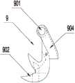
如图6a、6b、7a、7b所示出的,本发明的收拢夹包括相互嵌入配合的固定夹8和收拢夹9,固定夹8为勾爪型,固定夹8的顶部两端有两个销轴孔801,销轴孔801与连接架2上的倒置Y型连接板203的下端固定支脚204上的固定孔205对正,并采用销轴11固定;固定夹8的一侧设有导向块802,导向块802与固定夹8采用交错嵌入式设置,使得导向块802同时抵住固定夹8,对固定夹8起到加固作用,抵挡收拢夹9对固定夹8的冲击力的影响。勾爪型固定夹8的夹角处镶嵌有卡扣成型模10。As shown in Figures 6a, 6b, 7a, and 7b, the folding clip of the present invention includes a fixed
导向块802内有容纳n型龙门移动架3垂直边302的底脚滑轮303的滑槽803,滑槽803两侧分别设有导向滚轴804和导向轴承805,导向轴承805套在固定支脚204的销轴11上。导向滚轴804和导向轴承805配合引导n型龙门移动架3的垂直边302在滑槽803内顺畅上下运动。There is a
为了进一步保证推卡薄片5和勾型切刀6的性能,本发明在固定夹8中间进一步设计了一个容纳、引导勾型切刀6的切刀导槽,切刀导槽的两侧分别设置了容纳、引导推卡薄片5的导槽。前述的两种导槽均未在图中示出。In order to further ensure the performance of the
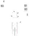
收拢夹9包括一蟹爪902,蟹爪902背部两侧反向延伸成形有两侧板903,两侧板903的端部具有销轴孔901,销轴孔901与固定支脚204上另一侧的固定孔205对正,并采用销轴11固定;两侧板903之间的空间成形为容纳n型龙门移动架3另一个末端滑轮303的滑道904。The
如图8所示出的,本发明的工作过程是:气缸杆101推动n型龙门移动架3向下垂直移动,带动推卡薄片5、勾型切刀6、收拢爪9和在弹簧705作用下的送卡扣机构706同时动作,实现送卡机构706向固定夹8两侧的送卡、收拢爪9逐步收拢肠衣、推卡薄片5推卡、直至打住卡扣。气缸上移时各动作反之;勾型切刀6切断肠衣、松开收拢夹6、卸出料管直至多用销轴401压紧送卡扣机构706。气缸1往复工作一次即可完成一个打卡循环。As shown in Figure 8, the working process of the present invention is: the
如上所述,对本发明的实施例进行了详细地说明,但是只要实质上没有脱离本发明的发明点及效果可以有很多的变形,这对本领域的技术人员来说是显而易见的。因此,这样的变形例也全部包含在本发明的保护范围之内。As mentioned above, although the Example of this invention was demonstrated in detail, it is obvious to those skilled in the art that many modifications can be made as long as the inventive point and effect of this invention are not substantially deviated. Therefore, all such modified examples are also included in the protection scope of the present invention.
Claims (13)
Priority Applications (5)
| Application Number | Priority Date | Filing Date | Title |
|---|---|---|---|
| CN201210013258.6ACN102556433B (en) | 2012-01-16 | 2012-01-16 | Dual-clamp card puncher with single cylinder and single claw |
| AU2012366094AAU2012366094B2 (en) | 2012-01-16 | 2012-04-28 | Single-cylinder single-claw double-card punching machine |
| PCT/CN2012/000570WO2013106971A1 (en) | 2012-01-16 | 2012-04-28 | Single-cylinder single-claw double-card punching machine |
| EP12865645.1AEP2805893A4 (en) | 2012-01-16 | 2012-04-28 | Single-cylinder single-claw double-card punching machine |
| US14/372,613US9902515B2 (en) | 2012-01-16 | 2012-04-28 | Single-cylinder single-claw double-card punching machine |
Applications Claiming Priority (1)
| Application Number | Priority Date | Filing Date | Title |
|---|---|---|---|
| CN201210013258.6ACN102556433B (en) | 2012-01-16 | 2012-01-16 | Dual-clamp card puncher with single cylinder and single claw |
Publications (2)
| Publication Number | Publication Date |
|---|---|
| CN102556433A CN102556433A (en) | 2012-07-11 |
| CN102556433Btrue CN102556433B (en) | 2014-06-11 |
Family
ID=46403374
Family Applications (1)
| Application Number | Title | Priority Date | Filing Date |
|---|---|---|---|
| CN201210013258.6AExpired - Fee RelatedCN102556433B (en) | 2012-01-16 | 2012-01-16 | Dual-clamp card puncher with single cylinder and single claw |
Country Status (5)
| Country | Link |
|---|---|
| US (1) | US9902515B2 (en) |
| EP (1) | EP2805893A4 (en) |
| CN (1) | CN102556433B (en) |
| AU (1) | AU2012366094B2 (en) |
| WO (1) | WO2013106971A1 (en) |
Families Citing this family (10)
| Publication number | Priority date | Publication date | Assignee | Title |
|---|---|---|---|---|
| CN103434682B (en)* | 2013-09-06 | 2015-02-18 | 陈声佩 | U-shaped fastener double-card punched-card machine |
| CN107662728A (en)* | 2016-07-27 | 2018-02-06 | 深圳市金奥博科技股份有限公司 | A kind of sealing device fed on the spinning device with aluminium wire |
| CN107788085A (en)* | 2017-11-24 | 2018-03-13 | 北京航天东方科技发展有限公司 | A kind of drive device of automatic filling clipper and clipper is filled automatically |
| CN108860796A (en)* | 2018-07-01 | 2018-11-23 | 曲靖凯利达工贸有限公司 | A kind of pneumatic punched-card machine |
| CN108930150B (en)* | 2018-08-21 | 2021-01-05 | 苏州汪永亨丝绸科技文化有限公司 | Silk product ironing mechanism |
| CN113271890B (en) | 2018-11-08 | 2024-08-30 | 内奥瓦斯克迪亚拉公司 | Ventricular deployment of transcatheter mitral valve prosthesis |
| CN110877240B (en)* | 2019-12-25 | 2024-09-06 | 无锡新柯工具制造有限公司 | Automatic clamping jaw of wood chisel |
| CN111874353B (en)* | 2020-07-21 | 2024-08-30 | 苏州嘉俊奥特威工业自动化有限公司 | A kind of pull-mouth mechanism for packaging machine |
| CN112157666B (en)* | 2020-09-01 | 2022-08-05 | 南京信息职业技术学院 | Multi-claw synchronous gathering paw |
| CN112219884A (en)* | 2020-10-19 | 2021-01-15 | 石家庄睿普雷健康科技有限公司 | Pneumatic disc type food packaging and card punching device |
Citations (2)
| Publication number | Priority date | Publication date | Assignee | Title |
|---|---|---|---|---|
| US5077955A (en)* | 1990-10-22 | 1992-01-07 | Delaware Capital Formation, Inc. | Chub packaging machine clipping mechanism |
| EP0488598A1 (en)* | 1990-11-26 | 1992-06-03 | Meiho Co., Ltd. | Hog ring clamping device |
Family Cites Families (33)
| Publication number | Priority date | Publication date | Assignee | Title |
|---|---|---|---|---|
| US293918A (en)* | 1884-02-19 | Machine for | ||
| US2899679A (en)* | 1959-08-18 | allen | ||
| US2176133A (en)* | 1937-09-20 | 1939-10-17 | Aluminum Co Of America | Sealing apparatus |
| US2722001A (en)* | 1950-10-03 | 1955-11-01 | Internat Staple And Machine Co | Retractable anvil stapling machine |
| US3064263A (en)* | 1958-04-28 | 1962-11-20 | Powers Wire Products Company I | Tool for applying hog-rings and the like |
| US3005988A (en)* | 1959-02-12 | 1961-10-31 | Joseph M Kirton | Stapling machine |
| US3783583A (en)* | 1972-09-22 | 1974-01-08 | Rheem Mfg Co | Gathering means for clippers |
| US4004339A (en)* | 1975-04-07 | 1977-01-25 | Rheem Manufacturing Company | Single piston operated clip device |
| US4214492A (en)* | 1978-12-26 | 1980-07-29 | Hoffman Thomas M | Method and apparatus for cutting clips off of the ends of sausages and the like |
| US5259168A (en)* | 1987-10-07 | 1993-11-09 | Delaware Capital Formation, Inc. | Continuously rotating platform with multiple mounted double clippers for continuously forming link product |
| US4821485A (en) | 1987-10-07 | 1989-04-18 | Delaware Capital Formation, Inc. | Continuously rotating platform with multiple mounted double clippers for continuously forming link product |
| US5020298A (en)* | 1987-10-07 | 1991-06-04 | Delaware Capital Formation, Inc. | Continuously rotating platform with multiple mounted double clippers for continuously forming link product |
| US5109648A (en)* | 1989-05-19 | 1992-05-05 | Delaware Capital Formation, Inc. | Packaging device with loop attachment mechanism and skin brake |
| US5209041A (en)* | 1990-10-22 | 1993-05-11 | Delaware Capital Formation, Inc. | Chub packaging machine clipping mechanism |
| DE4120440A1 (en)* | 1991-06-20 | 1992-12-24 | Hagedorn Kg Technopack Ewald | METHOD, MAGAZINE STRAND AND DEVICE FOR ATTACHING U-SHAPED BENDING CLAMPS |
| CN2248682Y (en)* | 1996-01-23 | 1997-03-05 | 石家庄市食品四厂 | Dual sealing machine for soft package of food |
| US5897066A (en)* | 1997-04-07 | 1999-04-27 | Forrest C. Bacon | Claw drum for shredding used carpet |
| US6604338B1 (en)* | 1998-10-02 | 2003-08-12 | Delaware Capital Formation, Inc. | Packaging device for attachment of clips to a continuously moving tube of casing |
| CN2404812Y (en)* | 1999-12-15 | 2000-11-08 | 衡水鸿昊企业有限责任公司 | Feeding device for clamping for clamping sealing machine |
| CN2404810Y (en)* | 1999-12-15 | 2000-11-08 | 衡水鸿昊企业有限责任公司 | Claming sealing driving device of double clamping sealing machine |
| IT1314415B1 (en)* | 2000-06-23 | 2002-12-13 | Vi Be Mac Spa | DEVICE TO CONTROL PRESSURE OF THE PRESSER FEET FOR SEWING MACHINES OR SIMILAR. |
| US20050072118A1 (en)* | 2003-10-03 | 2005-04-07 | Griggs Samuel D. | Netting chutes with ribbed flooring for manual and/or automated clipping packaging apparatus |
| WO2004104724A2 (en)* | 2003-05-14 | 2004-12-02 | Delaware Capital Formation, Inc. | Push/pull clip feed configuration for selectively delivering or withdrawing a clip to allow output of one clip alone or two clips concurrently and associated devices, methods, systems and computer program products |
| US7143566B2 (en)* | 2003-06-12 | 2006-12-05 | Delaware Capital Formation, Inc. | Clipper for automatic netting packaging machine |
| CN2656299Y (en)* | 2003-11-10 | 2004-11-17 | 闵小国 | Double fixture machine bayonet shaping mechanism |
| CN201080257Y (en)* | 2007-08-03 | 2008-07-02 | 石家庄晓进机械制造科技有限公司 | U-shaped double-fastener sealing machine |
| MX2010004307A (en)* | 2007-12-19 | 2010-05-14 | Tipper Tie Inc | Rotating multi-clipper platform systems with cooperating adhesive seal modules, adhesive seal systems and associated devices and related methods. |
| US9010072B2 (en)* | 2010-03-26 | 2015-04-21 | Tipper Tie, Inc. | Multiple station automated bagger systems, associated devices and related methods |
| CN202072021U (en)* | 2011-05-13 | 2011-12-14 | 孙聚远 | Dual grommet press machine |
| CN202593926U (en)* | 2012-01-16 | 2012-12-12 | 石家庄成功机电有限公司 | Single-cylinder and single-claw double card punching machine |
| AU2012379572B2 (en)* | 2012-05-10 | 2016-12-01 | Shijiazhuang Success Machinery Electrical Co., Ltd. | Continuous disk-type clipper device |
| USD737352S1 (en)* | 2013-08-09 | 2015-08-25 | Tipper Tie, Inc. | Spool mount for clippers on a rotating table |
| USD729294S1 (en)* | 2013-08-26 | 2015-05-12 | Tipper Tie, Inc. | Gripper for automated ruckers, reruckers, deruckers and/or skin brakes |
- 2012
- 2012-01-16CNCN201210013258.6Apatent/CN102556433B/ennot_activeExpired - Fee Related
- 2012-04-28USUS14/372,613patent/US9902515B2/ennot_activeExpired - Fee Related
- 2012-04-28AUAU2012366094Apatent/AU2012366094B2/ennot_activeCeased
- 2012-04-28WOPCT/CN2012/000570patent/WO2013106971A1/enactiveApplication Filing
- 2012-04-28EPEP12865645.1Apatent/EP2805893A4/ennot_activeWithdrawn
Patent Citations (2)
| Publication number | Priority date | Publication date | Assignee | Title |
|---|---|---|---|---|
| US5077955A (en)* | 1990-10-22 | 1992-01-07 | Delaware Capital Formation, Inc. | Chub packaging machine clipping mechanism |
| EP0488598A1 (en)* | 1990-11-26 | 1992-06-03 | Meiho Co., Ltd. | Hog ring clamping device |
Also Published As
| Publication number | Publication date |
|---|---|
| US20140359987A1 (en) | 2014-12-11 |
| EP2805893A1 (en) | 2014-11-26 |
| US9902515B2 (en) | 2018-02-27 |
| AU2012366094A1 (en) | 2014-08-14 |
| EP2805893A4 (en) | 2016-05-25 |
| CN102556433A (en) | 2012-07-11 |
| AU2012366094B2 (en) | 2016-01-14 |
| WO2013106971A1 (en) | 2013-07-25 |
Similar Documents
| Publication | Publication Date | Title |
|---|---|---|
| CN102556433B (en) | Dual-clamp card puncher with single cylinder and single claw | |
| CN203695798U (en) | Feeding mechanism of punch press | |
| CN103498291A (en) | Towel machine | |
| CN205086018U (en) | Automatic splitting machine | |
| CN109719791A (en) | Bamboo pulp paper wrapper production equipment | |
| WO2021103965A1 (en) | Synchronous pin detachment mechanism | |
| CN106001196A (en) | Bending machine | |
| KR101307875B1 (en) | Secondary battery electrode panel stamping apparatus | |
| CN107962100A (en) | A kind of sheet metal cutting equipment and its control method | |
| CN202208549U (en) | Automatic feeding device for plate workpieces | |
| CN203401350U (en) | An automatic edge-cutting machine for boards | |
| CN203045022U (en) | Copper starting sheet shearing machine | |
| CN103112026A (en) | Light-absorbing-piece cutting machine | |
| CN203221113U (en) | Bending machine punching tool | |
| CN206435871U (en) | A kind of cutting mechanism | |
| CN208628855U (en) | Profile drilling cutting all-in-one machine | |
| CN203475104U (en) | Towel machine | |
| CN202863818U (en) | Continuous disc type card punching device | |
| CN204276705U (en) | Deep drawing type product is without material strip conveyer | |
| CN202593926U (en) | Single-cylinder and single-claw double card punching machine | |
| CN205223688U (en) | Automatic clothes ironing equipment | |
| CN213107120U (en) | Full servo drive corrugated paper processing equipment | |
| CN203728292U (en) | Flat screen getting-on system | |
| CN106078941A (en) | Plate cutting Carving Machining integrated machine | |
| CN208277604U (en) | A kind of boiling hot machine of mobile picture |
Legal Events
| Date | Code | Title | Description |
|---|---|---|---|
| C06 | Publication | ||
| PB01 | Publication | ||
| C10 | Entry into substantive examination | ||
| SE01 | Entry into force of request for substantive examination | ||
| C14 | Grant of patent or utility model | ||
| GR01 | Patent grant | ||
| CF01 | Termination of patent right due to non-payment of annual fee | Granted publication date:20140611 | |
| CF01 | Termination of patent right due to non-payment of annual fee |