CN102556341A - Group flying robot with distribution and self-assembly characteristics - Google Patents
Group flying robot with distribution and self-assembly characteristicsDownload PDFInfo
- Publication number
- CN102556341A CN102556341ACN201110400157XACN201110400157ACN102556341ACN 102556341 ACN102556341 ACN 102556341ACN 201110400157X ACN201110400157X ACN 201110400157XACN 201110400157 ACN201110400157 ACN 201110400157ACN 102556341 ACN102556341 ACN 102556341A
- Authority
- CN
- China
- Prior art keywords
- module
- robot
- docking
- drive
- active
- Prior art date
- Legal status (The legal status is an assumption and is not a legal conclusion. Google has not performed a legal analysis and makes no representation as to the accuracy of the status listed.)
- Granted
Links
Images


Landscapes
- Manipulator (AREA)
Abstract
Translated fromChinese
Description
Translated fromChinese技术领域technical field
本发明涉及一种群体飞行机器人,该群体飞行机器人是由多个独立的群体飞行机器人单体组成,具有典型的分布式、自组装和模块化特点。The invention relates to a group flying robot, which is composed of a plurality of independent group flying robots and has typical characteristics of distribution, self-assembly and modularization.
背景技术Background technique
通过观察自然界社会性生物的群体自组织行为,人们意识到了群体机器人通过彼此协同在非结构化复杂多变的环境中执行任务时强大的功能扩展性、灵活性和适应性,开始了群体机器人理论和应用方面的研究。目前,群体机器人的研究领域主要局限在地面运动机器人的自组装、自重构和运动控制方面,对于在监控、探测、勘探、救灾和军事等领域有着广泛应用的飞行机器人领域的研究,大都还停留在构型固定的单个飞行器的控制和应用层面,由于受到其自身结构的限制,决定了其功能的单一化,无法适应复杂多变的环境和任务。虽然少有的一些研究涉及到了多个固定构型飞行器之间的协同和编队控制等内容,但是很少有涉及到具有分布式、自组装和模块化特点的群体飞行器的理论性和实用性的研究。群体机器人良好的扩展性、冗余性和鲁棒性没有能够在飞行机器人领域得到有效应用。By observing the group self-organization behavior of social creatures in nature, people realized the powerful functional scalability, flexibility and adaptability of group robots when they cooperate with each other to perform tasks in unstructured complex and changeable environments, and started the group robot theory and applied research. At present, the research field of swarm robots is mainly limited to the self-assembly, self-reconfiguration and motion control of ground-moving robots. For the research on flying robots, which are widely used in the fields of monitoring, detection, exploration, disaster relief and military affairs, most of them are still Staying at the control and application level of a single aircraft with a fixed configuration, due to the limitation of its own structure, determines the simplification of its functions and cannot adapt to complex and changeable environments and tasks. Although few studies have involved coordination and formation control between multiple fixed-configuration aircraft, few studies have involved the theoretical and practical aspects of distributed, self-assembled, and modular swarm aircraft. Research. The good scalability, redundancy and robustness of swarm robots have not been effectively applied in the field of flying robots.
发明内容Contents of the invention
本发明的目的在于提供一种具有分布式和自组装特征的群体飞行机器人,采用模块化的设计思想,群体飞行机器人由至少三个机器人单体组成,每个机器人单体都是一个完全自主的模块,可以通过机器人单体之间的自组装形成各种目标构型,具有更强的环境适应能力,并实现分布式的飞行控制。The object of the present invention is to provide a group flying robot with distributed and self-assembly features, adopting the modular design idea, the group flying robot is composed of at least three robot monomers, each robot monomer is a completely autonomous Modules can form various target configurations through self-assembly between robot monomers, have stronger environmental adaptability, and realize distributed flight control.
本发明采用以下技术方案实现:本发明是一种具有分布式和自组装特征的群体飞行机器人,采用模块化思想进行设计,群体飞行机器人由至少三个机器人单体组成,并且同时包括正桨和反桨机器人单体,每个机器人单体由地面运动模块、主动对接模块、被动对接模块、传感定位模块、飞行动力模块和控制模块组成。所述的正桨和反桨机器人单体主要是飞行动力模块中螺旋桨的倾角不同。The present invention is realized by the following technical solutions: the present invention is a distributed and self-assembled group flying robot, which is designed with the concept of modularization. Anti-propeller robot unit, each robot unit is composed of a ground motion module, an active docking module, a passive docking module, a sensor positioning module, a flight power module and a control module. The main difference between the forward propeller and reverse propeller robot is the inclination angle of the propeller in the flight power module.
所述的地面运动模块安装在机器人单体的底部,能够为机器人单体提供灵活而且全面的地面运动能力,采用的是多个全向轮在圆周空间上均匀布置的方案,每个全向轮由一个带码盘反馈的直流电机独立驱动控制,利用最少的资源实现机器人单体的主动全向驱动。The ground movement module is installed at the bottom of the robot body, which can provide flexible and comprehensive ground movement capabilities for the robot body. It adopts a scheme in which multiple omnidirectional wheels are evenly arranged in the circumferential space, and each omnidirectional wheel It is independently driven and controlled by a DC motor with code disk feedback, and the active omnidirectional drive of the robot is realized with the least resources.
所述的主动对接模块包括对接卡扣,被动对接模块上开有对接卡槽,机器人单体的各个侧面中有1个侧面为主动对接面,其余侧面为被动对接面。The active docking module includes a docking buckle, and the passive docking module is provided with a docking slot. Among the sides of the robot monomer, one side is an active docking surface, and the other sides are passive docking surfaces.
所述的传感定位模块包括布置在每个侧面上的一对模拟红外收发传感器,用于短距离的目标机器人测距定位以及避障;布置在每个侧面上的3个为一组的RGB三色一体LED,每组的3个LED都以一定的尺寸关系布置在三维的空间中,方便利用单目CMOS摄像头来观察定位;布置在主动对接面上的单目CMOS摄像头,以观察LED的成像尺寸来确定机器人单体之间的位置关系。The sensing and positioning module includes a pair of analog infrared transceiver sensors arranged on each side for short-distance target robot ranging positioning and obstacle avoidance; three RGB sensors arranged on each side as a group Three-color integrated LED, the three LEDs in each group are arranged in a three-dimensional space with a certain size relationship, which is convenient to use the monocular CMOS camera to observe and position; the monocular CMOS camera arranged on the active docking surface is used to observe the LED. The imaging size is used to determine the positional relationship between robot monomers.
所述的飞行动力模块根据螺旋桨的类别可以分成两类,“正桨模块”和“反桨模块”;所述的飞行动力模块包括1个螺旋桨、驱动该螺旋桨的直流无刷电机和设计在机体中间的圆形气流涵道。单个机器人单体不具有完整的飞行能力,但是多个正桨和反桨机器人单体对接组合之后便可以通过分布式协同控制获得完整的飞行功能。The flight power module can be divided into two categories according to the type of propeller, "forward propeller module" and "reverse propeller module"; the flight power module includes a propeller, a DC brushless motor driving the propeller and a The circular air duct in the middle. A single robot body does not have complete flight capabilities, but multiple forward propeller and anti-propeller robot monomers can obtain complete flight functions through distributed collaborative control after docking and combination.
所述的控制模块由1片ARM架构的处理器STM32 F103ZCT6做主控的算法,另1片ARM架构的处理器为核心的IMU模块做惯导姿态解算,底层以AVRMega8单片机为核心做所有电机(包括驱动螺旋桨的直流无刷电机和驱动全向轮的直流电机)的驱动控制和模拟红外收发传感器的信息采集;机器人单体之间的通信方式有两种选择:以cc2431为核心的Zigbee无线组网可以在机器人单体之间没有通过自组装建立物理连接之前以及组装后提供有效通信,机器人单体组装后还可以通过CAN总线物理连接建立通信。The control module is composed of one ARM architecture processor STM32 F103ZCT6 as the main control algorithm, another ARM architecture processor as the core IMU module for inertial navigation attitude calculation, and the bottom layer uses AVRMega8 single-chip microcomputer as the core to do all the motors (including DC brushless motors driving propellers and DC motors driving omnidirectional wheels) drive control and information collection of analog infrared transceiver sensors; there are two options for communication between robot monomers: Zigbee wireless with cc2431 as the core Networking can provide effective communication before and after the assembly of the robot monomers without establishing a physical connection through self-assembly. After the robot monomers are assembled, they can also establish communication through the physical connection of the CAN bus.
所述的具有分布式和自组装特征的群体飞行机器人,每个机器人单体的机体的机架结构由刚度较大、密度较轻的碳纤维方管搭建而成,机体外壳主要是采用EPP材料。In the group flying robot with distributed and self-assembly features, the frame structure of each robot body is made of carbon fiber square tubes with high rigidity and light density, and the shell of the body is mainly made of EPP material.
所述的具有分布式和自组装特征的群体飞行机器人能够通过机器人单体之间的相互对接连接形成各种构型,每个机器人单体的主动对接面可以和另外一个机器人单体的任何一个被动对接面对接,也可以和另一个机器人单体的主动对接面相互对接构成一个具有目标构型的群体飞行机器人;对于一种目标构型,机器人单体可以有多种不同的连接方式来实现,可以顺次相连形成一个环形的连接拓扑,也可以依次相连形成树形拓扑或者形成一种复合的网状拓扑。The group flying robot with distributed and self-assembly characteristics can form various configurations through the mutual docking connection between robot monomers, and the active docking surface of each robot monomer can be connected to any one of another robot monomer The passive docking surface can also be docked with the active docking surface of another robot monomer to form a group flying robot with a target configuration; for a target configuration, the robot monomer can have many different connection methods. For implementation, they can be connected in sequence to form a ring topology, or can be connected in sequence to form a tree topology or a composite mesh topology.
本发明的优点是:The advantages of the present invention are:
(1)将群体机器人“分布式”和“自组装”的特点引入群体飞行机器人的研究设计中,设计出一种能够自主对接成各种目标构型并以分布式策略控制飞行的群体飞行机器人。(1) Introduce the "distributed" and "self-assembly" characteristics of swarm robots into the research and design of swarm flying robots, and design a swarm flying robot that can autonomously dock into various target configurations and control flight with distributed strategies .
(2)采用模块化的设计思想,将机器人单体本身的各个主要功能部分区分成不同的设计模块,各个模块具有标准的连接接口,方便安装和维护。(2) Using the modular design concept, the main functional parts of the robot itself are divided into different design modules. Each module has a standard connection interface, which is convenient for installation and maintenance.
(3)地面运动方案采用全向轮建立起最简单的全向移动平台,使机器人拥有灵活的地面机动能力,方便快速运动到目标位置,提高自组装过程中的对接效率。(3) The ground motion scheme uses omni-directional wheels to establish the simplest omni-directional mobile platform, so that the robot has flexible ground maneuverability, convenient and fast movement to the target position, and improves the docking efficiency in the self-assembly process.
(4)设计了一种基于卡扣和卡槽的机械式对接卡紧机构及其相关的对称耦合曲柄摇杆驱动机构,相关的对接面分为主动对接面和被动对接面,每个机器人单体的主动对接面可以与另一个机器人单体的任意被动对接面或主动对接面对接。(4) A mechanical docking clamping mechanism based on buckles and slots and its related symmetrically coupled crank-rocker drive mechanism are designed. The related docking surfaces are divided into active docking surfaces and passive docking surfaces. Each robot unit The active docking surface of a robot body can be docked with any passive docking surface or active docking surface of another robot body.
(5)对接引导利用摄像头观察LED成像尺寸关系的方式来进行机器人之间相对位姿的准确定位,LED以一定的尺寸关系布置在三维的空间中,使得机器人之间的相对位姿关系能够通过一个单目摄像头成像完全确定。(5) Docking guidance uses the camera to observe the LED imaging size relationship to accurately locate the relative pose between the robots. The LEDs are arranged in a three-dimensional space with a certain size relationship, so that the relative pose relationship between the robots can be passed. A monocular camera imaging is completely determined.
(6)机身的结构和控制系统设计紧凑,分别采用EPP和碳纤维材料做外壳和机架,质量和体积都比较小。(6) The structure of the fuselage and the control system are compact in design, and the shell and frame are made of EPP and carbon fiber materials respectively, and the mass and volume are relatively small.
附图说明Description of drawings
图1是本发明具有分布式和自组装特征的群体飞行机器人的机器人单体的结构示意图;Fig. 1 is the structural representation of the robot monomer of the group flying robot with distributed and self-assembly characteristics of the present invention;
图2是地面运动模块布置示意图;Figure 2 is a schematic diagram of the layout of the ground movement module;
图3是主动对接模块和被动对接模块示意图;Fig. 3 is a schematic diagram of an active docking module and a passive docking module;
图3A、图3B是主动对接模块驱动机构简图;Fig. 3A and Fig. 3B are schematic diagrams of the driving mechanism of the active docking module;
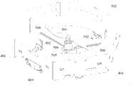
图4是传感定位模块和飞行动力模块布置示意图;Fig. 4 is a schematic diagram of the arrangement of the sensor positioning module and the flight power module;
图5是控制模块及机架和外壳的结构和外观示意图;Fig. 5 is a schematic diagram of the structure and appearance of the control module, the frame and the shell;
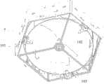
图6是三旋翼构型机器人;Fig. 6 is a three-rotor configuration robot;
图7是四旋翼构型机器人;Fig. 7 is a four-rotor configuration robot;
图8是多旋翼构型机器人。Figure 8 is a multi-rotor configuration robot.
图中:In the picture:
1.地面运动模块;2.主动对接模块;3.被动对接模块;4.传感定位模块;5.飞行动力模块;6.外壳;7.机架;8.机器人单体;9.机器人单体;10.机器人单体;11.控制模块 101.全向轮;102.直流电机;103.安装支座;201.对接卡扣;202.转动副;203.驱动连杆;204.驱动盘;205.驱动电机;206.驱动轴;301.对接卡槽;401.CMOS摄像头;402.顶部LED;403.底部LED;404.模拟红外收发传感器;501螺旋桨;502.直流无刷电机;503.气流涵道;504.电机安装盘;505.底座;506.支架。1. Ground movement module; 2. Active docking module; 3. Passive docking module; 4. Sensor positioning module; 5. Flight power module; Body; 10. Robot monomer; 11.
具体实施方式Detailed ways
下面将结合附图和实施例对本发明做进一步的详细说明:The present invention will be described in further detail below in conjunction with accompanying drawing and embodiment:
本发明的具有分布式和自组装特征的群体飞行机器人,每个群体飞行机器人由至少三个机器人单体组成,并且三个机器人单体中要同时包括正桨机器人单体和反桨机器人单体。所述的机器人单体如图1所示,具有规则的几何外形结构,可以是三角形、四边形、五边形或者六边形等多边形的中空柱体结构(或者称为中空棱柱结构),所述的中空柱体结构是由外壳6包覆机架7(如图5)形成的,每个机器人单体由地面运动模块1、主动对接模块2、被动对接模块3、传感定位模块4、飞行动力模块5和控制模块11(如图5)组成,每个模块都有特定的尺寸和独立的功能,模块之间有良好的通用性和可交换性,图1展示了一个完整功能的机器人单体的实施例,所述的实施例中的机器人单体为六边形的中空棱柱结构,外壳6内部为所包覆的机架7,所述的地面运动模块1、主动对接模块2、被动对接模块3、传感定位模块4、飞行动力模块5和控制模块11均连接设置在机架7上。多个机器人单体之间通过相关模块的连接组合可以得到多变的整体形态和构型,具有简单的本体结构,丰富的形态构型和强大的适应能力。In the distributed and self-assembled swarm flying robot of the present invention, each swarm flying robot is composed of at least three robot units, and the three robot units must include both forward propeller robot units and reverse propulsion robot units . As shown in Figure 1, the robot monomer has a regular geometric shape structure, which can be a hollow cylinder structure (or a hollow prism structure) of polygons such as triangles, quadrilaterals, pentagons or hexagons. The hollow cylinder structure is formed by the
如图1和图2所示,所述的地面运动模块1安装在机器人单体的机架7的底部,主要由全向轮101、直流电机102和安装支座103构成,优选的,本实施例中在每个机器人单体的机架7底部共布置有三个全向轮101,角度间距为120度,均匀分布在底盘圆周空间上,每个全向轮101均与一个直流电机102输出轴直接连接;所述的直流电机102为带有增量式编码器的闭环直流伺服电机,也称直流编码反馈电机。所述的安装支座103固定在机架7上,安装支座103上开有电机安装槽,直流电机102可以部分插入电机安装槽内并通过螺纹连接固定在安装支座103上。所述的全向轮101可以设置多个,连接方式与三个全向轮101的连接方式相同。As shown in Figures 1 and 2, the
请参见图3所示,所述的主动对接模块2和被动对接模块3设置在机器人单体的侧面上,其中一个侧面上设置为主动对接模块2,称为主动对接面,其余侧面上均设置为被动对接模块3,称为被动对接面,所述的主动对接模块2包括一对主动对接卡扣201,两个对接卡扣201在高度方向和水平方向上都要错开一定的距离,即两个对接卡口201高度设置不同。在本实施例中,两个对接卡口201垂直高度方向间距15mm,水平间距80mm;所述的被动对接模块3是指与对接卡扣201对应的对接卡槽301,设置在主动对接面和被动对接面上,两个对接卡槽301和所述的对接卡扣201相互配合卡紧即可实现两个机器人单体的有效连接;所述的对接卡扣201的驱动模块采用对称耦合曲柄摇杆形式驱动,通过一部卡扣驱动电机205驱动两个对接卡扣201同时对称动作实现对接卡扣的开合。如图3A、3B所示,两个对接卡扣201分别通过两个转动副202转动连接在机架7上,两个对接卡扣201上分别连接有驱动连杆203,所述的两个驱动连杆203的另一端连接在驱动盘204上,所述的驱动盘204位于两个对接卡扣201中间的位置,驱动盘204中心固定连接驱动电机205的驱动轴206,在驱动电机205的驱动下,驱动轴206带动驱动盘204转动,进而通过驱动盘204上的驱动连杆203带动对接卡扣201转动,实现对接卡扣201与对接卡槽301的开合对接,这样,就可以实现两个机器人单体之间的连接,将两个机器人单体组装。Please refer to Fig. 3, the
请参见图4所示,所述的传感定位模块4主要包括一个CMOS摄像头401、一个顶部LED402、两个底部LED 403和两个模拟红外收发传感器404,所述的CMOS摄像头401安装在机器人单体的主动对接面上;所述的一个顶部LED402和两个底部LED403组成LED组,在机器人单体的每个侧面上都布置一个LED组,其中两个底部LED403间隔布置在机器人单体的侧面上,顶部LED402布置在靠近机体内侧的位置,高度比底部LED403高,从主动对接面的正面观察,CMOS摄像头401恰好位于三个以LED为顶点的三角形的几何中心位置。所述的模拟红外收发传感器404也设置在机器人单体的每个侧面上,并且优选的将两个模拟红外收发传感器404之间的水平距离大于所在侧面上的两个底部LED403之间的距离,即将两个模拟红外收发传感器404设置在尽量靠近所在侧面的两侧边缘位置。所述的顶部LED402的高度高于CMOS摄像头401的高度,保证在实现对接的时候,每个CMOS摄像头401可以看到LED组的每个LED。优选的,所述的底部LED403位置高于两个模拟红外收发传感器404的位置,两个模拟红外收发传感器404的位置高于对接卡口201或者对接卡槽301的位置。Please refer to shown in Fig. 4, described sensing positioning module 4 mainly comprises a
所述的飞行动力模块5主要由螺旋桨501、直流无刷电机502和气流涵道503构成,优选的,其中所述的螺旋桨501为双叶型的单旋翼慢速桨,直接紧固安装在直流无刷电机502的输出轴上;所述的直流无刷电机502通过螺纹连接固定在底座505的电机安装盘504上,所述的底座505是与机架7连接固定的,如图4所示,底座505可以通过三条支架506连接到机架7上;所述的气流涵道503是一个由EPP材料的机壳6形成的圆形气流通道,气流涵道503与螺旋桨501的配合,能够增压增力,驱动机器人单体的飞行。The flight power module 5 is mainly composed of a
本发明的具有分布式和自组装特征的群体飞行机器人,其特点是机器人单体根据所安装的螺旋桨501的桨叶倾角方向不同,(所述的倾角方向是指螺旋桨的桨叶平面和桨的转轴垂直平面的夹角,如果定义正桨夹角为正则反桨夹角即为负)分为正桨机器人单体和反桨机器人单体两类,如图6,图7和图8。当机器人单体组装形成具有飞行能力的群体飞行机器人时,至少要有一个正桨机器人单体和一个反桨机器人单体。The group flying robot with distribution and self-assembly characteristics of the present invention is characterized in that the direction of the blade inclination angle of the robot monomer is different according to the installed
请参见图5所示,本发明的机器人单体的外壳6采用EPP泡沫材料,机架7采用轻质的碳纤维方管,外壳6包覆在机架7的外面,形成外形为中空的六棱柱,该中空结构就作为螺旋桨501的气流涵道503。在机架7上连结固定有地面驱动模块1、主动对接模块2、被动对接模块3、传感定位模块4和飞行动力模块5的相应位置的外壳6上设置有开孔,这样既保证了上述各模块的安装稳固,又起到了一定的保护作用,尤其是对传感定位模块4的保护,避免的机器人单体对接的时候发生碰撞和摩擦损害。Please refer to shown in Fig. 5, the
本发明的具有分布式和自组装特征的群体飞行机器人,通过主动对接模块2的对接卡扣201和主动对接模块2或被动对接模块3的对接卡槽301相互配合卡紧组成一个拥有某种构型的整体机器人。一种比较基础和简单的构型如图6所示,机器人单体10(正桨机器人单体)的主动对接面卡紧机器人单体9(反桨机器人单体)的一个被动对接面,机器人单体9的主动对接面卡紧机器人单体8(正桨机器人单体)的一个被动对接面,机器人单体8的主动对接面卡紧机器人单体10的一个被动对接面,3个基本的机器人单体之间通过相互顺次卡紧的方式形成一个三旋翼的构型。如图7所示,四个机器人单体通过顺次卡紧可以实现一个常见的四旋翼构型的整体机器人,其中包括两个正桨机器人单体和两个反桨机器人单体;更一般的,多个正桨和反桨机器人单体之间通过对接卡紧,可以实现机器人构型空间内所有目标构型的建立,如图8所示,形成一个适应具体环境和应用要求的整体机器人,由八个机器人单体组成,正桨和反桨机器人单体的选取可以根据飞控算法可控空间进行合理选取。The group flying robot with distributed and self-assembly features of the present invention forms a robot with a certain structure by cooperating with the
请参见图9所示,所述的控制模块11连结在机架7上,控制模块11的主控电路板采用STM32 F103ZCT6,设置在主动对接面所对应位置的机架7上,地面运动模块1和传感定位模块4由3个AVRMega8(MEGA8)控制,具体为每个MEGA8负责控制一个地面驱动模块1中的全向轮101、两个传感定位模块4中的LED组和模拟红外收发传感器404。飞行控制模块5中的直流无刷电机502通过1个MEGA8控制的电调板驱动,机器人单体的姿态测量由以第二块STM32处理器为核心的IMU模块完成,所述的IMU模块为集成有三轴加速度计、三轴陀螺仪和三轴地磁传感器的九轴复合IMU模块,以上所述的IMU模块和MEGA8控制板都挂靠在I2C总线上,通过I2C总线与主控电路板通信并由主控电路板来控制。所述的主控电路板上预留有PPM遥控编码(MEGA128 PPM Ecoder)的信息接收通道,通过处理器的ICP(Input Signal Capture)通道解码遥控指令,方便飞控调试;无线通信的Zigbee模块以具有定位功能的cc2431为核心,通过USART(Universal Synchronous/AsynchronousReceiver/Transmitter)接受主控控制,不同的机器人单体之间的通信有Zigbee和CAN两种选择方式:以cc2431为核心的Zigbee无线组网可以在机器人单体之间没有通过自组装建立物理连接之前以及组装后提供有效通信,机器人单体组装后可以通过CAN总线物理连接建立通信。Please refer to shown in Fig. 9, described
所述的MEGA8的数量根据地面运动模块1上全向轮101的设置数量以及机器人单体的棱柱结构的侧面个数,可以进行调整,MEGA8也连结在机架7上。本实施例中,三个全向轮101,因此设置三个MEGA8,每个MEGA8负责控制一个全向轮,同时,每个MEGA8还分别用来负责控制与其相邻的两个侧面上的传感定位模块4中的LED组和模拟红外收发传感器404。The quantity of the MEGA8 can be adjusted according to the number of
本发明的具有分布式和自组装特征的群体飞行机器人,将群体机器人“分布式”和“自组装”的特点引入飞行机器人的研究设计中,突破了传统群体机器人研究领域的限制,设计出一种能够自主对接成各种目标构型并以分布式策略控制飞行的群体飞行机器人;采用模块化的设计思想,机器人结构简单,成本低廉,对各种复杂环境和应用要求都有较强的适应性和扩展性。The distributed and self-assembled swarm flying robot of the present invention introduces the "distributed" and "self-assembled" characteristics of swarm robots into the research and design of flying robots, breaks through the limitations of the traditional swarm robot research field, and designs a A group flying robot that can autonomously dock into various target configurations and control the flight with a distributed strategy; adopts the modular design idea, the robot has a simple structure, low cost, and has a strong adaptability to various complex environments and application requirements and scalability.
以上所述,仅为本发明较佳的具体实施方式之一,但本发明的保护范围并不局限于此,任何熟悉本技术领域的技术人员在本发明揭露的技术范围内,可以轻易想到的变化或替代,都应涵盖在本发明的保护范围之内。The above description is only one of the preferred specific embodiments of the present invention, but the protection scope of the present invention is not limited thereto. Anyone familiar with the technical field can easily think of Any changes or substitutions shall fall within the protection scope of the present invention.
Claims (5)
Translated fromChinesePriority Applications (1)
| Application Number | Priority Date | Filing Date | Title |
|---|---|---|---|
| CN201110400157XACN102556341B (en) | 2011-12-05 | 2011-12-05 | Group flying robot with distribution and self-assembly characteristics |
Applications Claiming Priority (1)
| Application Number | Priority Date | Filing Date | Title |
|---|---|---|---|
| CN201110400157XACN102556341B (en) | 2011-12-05 | 2011-12-05 | Group flying robot with distribution and self-assembly characteristics |
Publications (2)
| Publication Number | Publication Date |
|---|---|
| CN102556341Atrue CN102556341A (en) | 2012-07-11 |
| CN102556341B CN102556341B (en) | 2013-11-13 |
Family
ID=46403301
Family Applications (1)
| Application Number | Title | Priority Date | Filing Date |
|---|---|---|---|
| CN201110400157XAActiveCN102556341B (en) | 2011-12-05 | 2011-12-05 | Group flying robot with distribution and self-assembly characteristics |
Country Status (1)
| Country | Link |
|---|---|
| CN (1) | CN102556341B (en) |
Cited By (32)
| Publication number | Priority date | Publication date | Assignee | Title |
|---|---|---|---|---|
| CN102913275A (en)* | 2012-11-01 | 2013-02-06 | 金纯� | Search and rescue system based on crawler robots |
| CN103217700A (en)* | 2013-04-10 | 2013-07-24 | 南昌大学 | GPS (global positioning system), IMU (inertial measurement unit), magnetometer and barometer combinational navigation system device |
| CN103353768A (en)* | 2013-06-18 | 2013-10-16 | 陕西理工学院 | Three-quadrant sunshine tracking sensing apparatus |
| CN104089617A (en)* | 2014-07-31 | 2014-10-08 | 四川阿泰因机器人智能装备有限公司 | Locating device and method for mobile robot |
| CN104590553A (en)* | 2015-01-05 | 2015-05-06 | 惠州市加迈电器有限公司 | Rescue equipment |
| CN105644777A (en)* | 2016-03-17 | 2016-06-08 | 中国直升机设计研究所 | Assembly type multi-rotor aerocraft |
| CN105799923A (en)* | 2016-04-28 | 2016-07-27 | 南京信息工程大学 | Four-rotor aircraft-based carrying manipulator |
| CN106005361A (en)* | 2016-04-07 | 2016-10-12 | 珠海市磐石电子科技有限公司 | Aviation power unit and flight frame and modularization aircraft thereof |
| CN106339553A (en)* | 2016-08-29 | 2017-01-18 | 华东师范大学 | Method and system for reconstructing flight control of spacecraft |
| CN106354930A (en)* | 2016-08-29 | 2017-01-25 | 华东师范大学 | Adaptive reconstruction method and system for spacecraft |
| CN106427436A (en)* | 2015-08-10 | 2017-02-22 | 汤翠华 | Modularization all-terrain traffic device |
| CN106794895A (en)* | 2016-05-18 | 2017-05-31 | 深圳市创客工场科技有限公司 | Multi-rotor aerocraft |
| CN106828896A (en)* | 2016-12-29 | 2017-06-13 | 东莞产权交易中心 | Modularization concatenation formula unmanned aerial vehicle |
| CN107000837A (en)* | 2016-05-18 | 2017-08-01 | 深圳市创客工场科技有限公司 | It is a kind of can ground running unmanned plane |
| CN107263457A (en)* | 2017-06-22 | 2017-10-20 | 清华大学 | Split type robot and combinations thereof, separation method |
| CN107472521A (en)* | 2017-06-22 | 2017-12-15 | 深圳大学 | The control method of more rotor flying platforms and more rotor flying platforms |
| CN107963204A (en)* | 2017-11-13 | 2018-04-27 | 西北工业大学 | One kind is based on modular combination culvert type rotor wing unmanned aerial vehicle |
| CN108394242A (en)* | 2018-05-15 | 2018-08-14 | 西南交通大学 | A kind of air-ground amphibious modularization robot |
| CN108557073A (en)* | 2018-02-06 | 2018-09-21 | 雷安静 | A kind of duct unmanned aerial vehicle Systems Air performance method |
| CN108557072A (en)* | 2018-02-06 | 2018-09-21 | 雷安静 | A kind of duct unmanned aerial vehicle air show system |
| CN108725765A (en)* | 2017-04-17 | 2018-11-02 | 深圳市静享科技有限公司 | A kind of means of transport of extreme low-altitude safe flight |
| CN109334968A (en)* | 2018-02-06 | 2019-02-15 | 酷黑科技(北京)有限公司 | Ducted aircraft capable of aerial real-time reconfiguration, docking and separation method and system |
| CN109398704A (en)* | 2018-12-19 | 2019-03-01 | 向杰 | A kind of urgent transport flight equipment |
| EP3450309A1 (en)* | 2017-08-28 | 2019-03-06 | Airbus Operations GmbH | A coupling device for coupling modules with each other, aircraft comprising the coupling device, method for the coupling and decoupling of modules |
| CN109460060A (en)* | 2018-12-05 | 2019-03-12 | 四川航天系统工程研究所 | It is unmanned to equip intelligent coordinated control assembly and control method |
| CN109703751A (en)* | 2019-02-22 | 2019-05-03 | 中船重工(武汉)凌久信息技术有限公司 | A military detection aircraft |
| CN110065071A (en)* | 2019-05-11 | 2019-07-30 | 西安电子科技大学 | A kind of group's self assembly robot modeling method based on the description of three element configurations |
| CN112318504A (en)* | 2020-10-28 | 2021-02-05 | 浙江树人学院(浙江树人大学) | A multi-sensor industrial robot cooperative motion device and its control method |
| CN113165728A (en)* | 2019-12-03 | 2021-07-23 | 向杰 | Honeycomb array multi-rotor composite part, rack and aircraft |
| CN115122306A (en)* | 2022-07-28 | 2022-09-30 | 哈尔滨工业大学(深圳) | Rotationally symmetrical reconfigurable robot platform and method therefor |
| CN116022324A (en)* | 2023-01-04 | 2023-04-28 | 浙江大学 | Chain type autonomous splicing and reconstructing modularized aerial robot |
| CN118928802B (en)* | 2024-08-26 | 2025-10-17 | 西北工业大学 | Reconfigurable modularized robot structure for airplane surface quality detection |
Families Citing this family (2)
| Publication number | Priority date | Publication date | Assignee | Title |
|---|---|---|---|---|
| EP3445651A1 (en)* | 2016-04-22 | 2019-02-27 | Gozluklu, Burak | Three dimensional scalable and modular aircraft |
| CN111666215A (en)* | 2020-06-04 | 2020-09-15 | 清华大学 | Desktop cluster hardware platform for distributed algorithm testing and human-computer interaction research |
Citations (4)
| Publication number | Priority date | Publication date | Assignee | Title |
|---|---|---|---|---|
| JP2005125466A (en)* | 2003-10-27 | 2005-05-19 | Sharp Corp | Group robot system, sensing robot included in group robot system, base station included in group robot system, and pheromone robot included in group robot system |
| CN101549494A (en)* | 2009-05-11 | 2009-10-07 | 北京航空航天大学 | Monomer automatic transformable robot with self-assembly characteristic |
| CN101890724A (en)* | 2010-07-02 | 2010-11-24 | 上海理工大学 | SWARM robot module standard quick change interface |
| CN101913152A (en)* | 2010-07-23 | 2010-12-15 | 上海理工大学 | Swarm-robot passive rotating assembly |
- 2011
- 2011-12-05CNCN201110400157XApatent/CN102556341B/enactiveActive
Patent Citations (4)
| Publication number | Priority date | Publication date | Assignee | Title |
|---|---|---|---|---|
| JP2005125466A (en)* | 2003-10-27 | 2005-05-19 | Sharp Corp | Group robot system, sensing robot included in group robot system, base station included in group robot system, and pheromone robot included in group robot system |
| CN101549494A (en)* | 2009-05-11 | 2009-10-07 | 北京航空航天大学 | Monomer automatic transformable robot with self-assembly characteristic |
| CN101890724A (en)* | 2010-07-02 | 2010-11-24 | 上海理工大学 | SWARM robot module standard quick change interface |
| CN101913152A (en)* | 2010-07-23 | 2010-12-15 | 上海理工大学 | Swarm-robot passive rotating assembly |
Non-Patent Citations (1)
| Title |
|---|
| 魏洪兴等: "模块化群体机器人构型分析与自组装控制", 《机械工程学报》, vol. 46, no. 13, 31 July 2010 (2010-07-31), pages 100 - 107* |
Cited By (50)
| Publication number | Priority date | Publication date | Assignee | Title |
|---|---|---|---|---|
| CN102913275A (en)* | 2012-11-01 | 2013-02-06 | 金纯� | Search and rescue system based on crawler robots |
| CN102913275B (en)* | 2012-11-01 | 2014-09-17 | 金纯� | Search and rescue system based on crawler robots |
| CN103217700A (en)* | 2013-04-10 | 2013-07-24 | 南昌大学 | GPS (global positioning system), IMU (inertial measurement unit), magnetometer and barometer combinational navigation system device |
| CN103353768A (en)* | 2013-06-18 | 2013-10-16 | 陕西理工学院 | Three-quadrant sunshine tracking sensing apparatus |
| CN104089617A (en)* | 2014-07-31 | 2014-10-08 | 四川阿泰因机器人智能装备有限公司 | Locating device and method for mobile robot |
| CN104089617B (en)* | 2014-07-31 | 2017-07-04 | 四川阿泰因机器人智能装备有限公司 | A kind of mobile robot positioner and localization method |
| CN104590553A (en)* | 2015-01-05 | 2015-05-06 | 惠州市加迈电器有限公司 | Rescue equipment |
| CN104590553B (en)* | 2015-01-05 | 2017-06-20 | 泉州东行贸易有限公司 | Rescue aid |
| CN106427436A (en)* | 2015-08-10 | 2017-02-22 | 汤翠华 | Modularization all-terrain traffic device |
| CN105644777A (en)* | 2016-03-17 | 2016-06-08 | 中国直升机设计研究所 | Assembly type multi-rotor aerocraft |
| CN106005361A (en)* | 2016-04-07 | 2016-10-12 | 珠海市磐石电子科技有限公司 | Aviation power unit and flight frame and modularization aircraft thereof |
| CN106005361B (en)* | 2016-04-07 | 2019-06-28 | 珠海市磐石电子科技有限公司 | Aviation power unit and flight frame and modularization aircraft thereof |
| CN105799923A (en)* | 2016-04-28 | 2016-07-27 | 南京信息工程大学 | Four-rotor aircraft-based carrying manipulator |
| CN106794895B (en)* | 2016-05-18 | 2020-04-17 | 深圳市创客工场科技有限公司 | Multi-rotor aircraft |
| CN107000837B (en)* | 2016-05-18 | 2020-10-13 | 深圳市创客工场科技有限公司 | Unmanned aerial vehicle capable of walking on ground |
| CN106794895A (en)* | 2016-05-18 | 2017-05-31 | 深圳市创客工场科技有限公司 | Multi-rotor aerocraft |
| CN107000837A (en)* | 2016-05-18 | 2017-08-01 | 深圳市创客工场科技有限公司 | It is a kind of can ground running unmanned plane |
| EP3459846A4 (en)* | 2016-05-18 | 2020-01-15 | Makeblock Co., Ltd. | MULTIPLE ROTOR AIRCRAFT |
| WO2017197602A1 (en)* | 2016-05-18 | 2017-11-23 | 深圳市创客工场科技有限公司 | Multi-rotor aircraft |
| US11027832B2 (en) | 2016-05-18 | 2021-06-08 | Makeblock Co., Ltd. | Multi-rotor aircraft |
| CN106339553B (en)* | 2016-08-29 | 2019-06-21 | 华东师范大学 | A reconfigured flight control method and system for a space vehicle |
| CN106339553A (en)* | 2016-08-29 | 2017-01-18 | 华东师范大学 | Method and system for reconstructing flight control of spacecraft |
| CN106354930A (en)* | 2016-08-29 | 2017-01-25 | 华东师范大学 | Adaptive reconstruction method and system for spacecraft |
| CN106354930B (en)* | 2016-08-29 | 2019-06-21 | 华东师范大学 | Adaptive reconstruction method and system for a space vehicle |
| CN106828896A (en)* | 2016-12-29 | 2017-06-13 | 东莞产权交易中心 | Modularization concatenation formula unmanned aerial vehicle |
| CN108725765A (en)* | 2017-04-17 | 2018-11-02 | 深圳市静享科技有限公司 | A kind of means of transport of extreme low-altitude safe flight |
| CN107472521A (en)* | 2017-06-22 | 2017-12-15 | 深圳大学 | The control method of more rotor flying platforms and more rotor flying platforms |
| CN107263457A (en)* | 2017-06-22 | 2017-10-20 | 清华大学 | Split type robot and combinations thereof, separation method |
| EP3450309A1 (en)* | 2017-08-28 | 2019-03-06 | Airbus Operations GmbH | A coupling device for coupling modules with each other, aircraft comprising the coupling device, method for the coupling and decoupling of modules |
| CN107963204A (en)* | 2017-11-13 | 2018-04-27 | 西北工业大学 | One kind is based on modular combination culvert type rotor wing unmanned aerial vehicle |
| CN107963204B (en)* | 2017-11-13 | 2020-09-22 | 西北工业大学 | Duct type rotor unmanned aerial vehicle based on modular combination |
| CN108557072A (en)* | 2018-02-06 | 2018-09-21 | 雷安静 | A kind of duct unmanned aerial vehicle air show system |
| CN109334968A (en)* | 2018-02-06 | 2019-02-15 | 酷黑科技(北京)有限公司 | Ducted aircraft capable of aerial real-time reconfiguration, docking and separation method and system |
| WO2019154118A1 (en)* | 2018-02-06 | 2019-08-15 | 酷黑科技(北京)有限公司 | Ducted aircraft capable of implementing aerial reconstruction in real time, and docking separation method and system |
| CN108557073A (en)* | 2018-02-06 | 2018-09-21 | 雷安静 | A kind of duct unmanned aerial vehicle Systems Air performance method |
| CN108394242A (en)* | 2018-05-15 | 2018-08-14 | 西南交通大学 | A kind of air-ground amphibious modularization robot |
| CN109460060A (en)* | 2018-12-05 | 2019-03-12 | 四川航天系统工程研究所 | It is unmanned to equip intelligent coordinated control assembly and control method |
| CN109398704A (en)* | 2018-12-19 | 2019-03-01 | 向杰 | A kind of urgent transport flight equipment |
| CN109703751A (en)* | 2019-02-22 | 2019-05-03 | 中船重工(武汉)凌久信息技术有限公司 | A military detection aircraft |
| CN109703751B (en)* | 2019-02-22 | 2022-01-28 | 韩绍泽 | Military detection flight instrument |
| CN110065071A (en)* | 2019-05-11 | 2019-07-30 | 西安电子科技大学 | A kind of group's self assembly robot modeling method based on the description of three element configurations |
| CN110065071B (en)* | 2019-05-11 | 2021-11-09 | 西安电子科技大学 | Group self-assembly robot configuration method based on three-element configuration description |
| CN113165728A (en)* | 2019-12-03 | 2021-07-23 | 向杰 | Honeycomb array multi-rotor composite part, rack and aircraft |
| CN112318504A (en)* | 2020-10-28 | 2021-02-05 | 浙江树人学院(浙江树人大学) | A multi-sensor industrial robot cooperative motion device and its control method |
| CN112318504B (en)* | 2020-10-28 | 2021-09-14 | 浙江树人学院(浙江树人大学) | Multi-sensor industrial robot cooperative motion device and control method thereof |
| CN115122306A (en)* | 2022-07-28 | 2022-09-30 | 哈尔滨工业大学(深圳) | Rotationally symmetrical reconfigurable robot platform and method therefor |
| CN115122306B (en)* | 2022-07-28 | 2024-05-10 | 哈尔滨工业大学(深圳) | Rotationally symmetrical reconfigurable robot platform and method thereof |
| CN116022324A (en)* | 2023-01-04 | 2023-04-28 | 浙江大学 | Chain type autonomous splicing and reconstructing modularized aerial robot |
| CN116022324B (en)* | 2023-01-04 | 2024-04-12 | 浙江大学 | A modular aerial robot with chain-like autonomous splicing and reconstruction |
| CN118928802B (en)* | 2024-08-26 | 2025-10-17 | 西北工业大学 | Reconfigurable modularized robot structure for airplane surface quality detection |
Also Published As
| Publication number | Publication date |
|---|---|
| CN102556341B (en) | 2013-11-13 |
Similar Documents
| Publication | Publication Date | Title |
|---|---|---|
| CN102556341A (en) | Group flying robot with distribution and self-assembly characteristics | |
| CN205891228U (en) | Flying robot | |
| Dorigo et al. | Swarmanoid: a novel concept for the study of heterogeneous robotic swarms | |
| CN113844221B (en) | Amphibious three-mode flight adsorption wall climbing robot and control method | |
| CN104494818B (en) | Four rotor amphibious robots | |
| KR101627042B1 (en) | Reconfigurable Aerial Vehicle Based on Multi-rotor | |
| US8794564B2 (en) | Vehicle capable of in-air and on-ground mobility | |
| US8794566B2 (en) | Vehicle capable of stabilizing a payload when in motion | |
| CN103645740B (en) | Based on the intelligent cruise robot of wireless charging odd number axle aircraft | |
| CN112678169B (en) | Multi-mode flying robot and mode changing method thereof | |
| CN107804474B (en) | Design method of complete machine system of multi-rotor flying robot with redundant mechanical arm | |
| CN202071985U (en) | Novel plane symmetrical layout type multi-rotor unmanned air vehicle | |
| CN105857593B (en) | A four-rotor multi-purpose flying robot | |
| CN113342058B (en) | Multi-purpose unmanned system with platura stereo structure | |
| CN105966488A (en) | Six-wheel-leg movable operation robot test platform | |
| CN104875890B (en) | Quadrotor | |
| EP3649046A1 (en) | Portable integrated uav | |
| US11702203B2 (en) | Group configurations for a modular drone system | |
| CN216069511U (en) | Amphibious three-modal flying adsorption wall-climbing robot | |
| US10974825B2 (en) | Aerial system including foldable frame architecture | |
| CN105799923A (en) | Four-rotor aircraft-based carrying manipulator | |
| CN204515534U (en) | Based on the miniature quadrotor that STM32 controls | |
| CN111137082A (en) | Single-duct land air cross-domain robot and control method thereof | |
| CN106628126A (en) | Unmanned aerial vehicle capable of taking off and landing on slope | |
| CN105573316A (en) | Autonomous-formation mobile swarm robot |
Legal Events
| Date | Code | Title | Description |
|---|---|---|---|
| C06 | Publication | ||
| PB01 | Publication | ||
| C10 | Entry into substantive examination | ||
| SE01 | Entry into force of request for substantive examination | ||
| C14 | Grant of patent or utility model | ||
| GR01 | Patent grant | ||
| TR01 | Transfer of patent right | ||
| TR01 | Transfer of patent right | Effective date of registration:20230801 Address after:Room 407, building 5, yard 98, lianshihu West Road, Mentougou District, Beijing 102300 Patentee after:AUBO (Beijing) Intelligent Technology Co.,Ltd. Address before:100191 No. 37, Haidian District, Beijing, Xueyuan Road Patentee before:BEIHANG University |