CN102555549A - Printing device and control method therefor - Google Patents
Printing device and control method thereforDownload PDFInfo
- Publication number
- CN102555549A CN102555549ACN2011103892562ACN201110389256ACN102555549ACN 102555549 ACN102555549 ACN 102555549ACN 2011103892562 ACN2011103892562 ACN 2011103892562ACN 201110389256 ACN201110389256 ACN 201110389256ACN 102555549 ACN102555549 ACN 102555549A
- Authority
- CN
- China
- Prior art keywords
- printing
- area
- amount
- recording paper
- blank
- Prior art date
- Legal status (The legal status is an assumption and is not a legal conclusion. Google has not performed a legal analysis and makes no representation as to the accuracy of the status listed.)
- Granted
Links
- 238000000034methodMethods0.000titleclaimsabstractdescription50
- 238000012937correctionMethods0.000claimsabstractdescription57
- 230000009466transformationEffects0.000claimsabstractdescription9
- 238000003780insertionMethods0.000claimsdescription59
- 230000037431insertionEffects0.000claimsdescription59
- 238000001514detection methodMethods0.000claimsdescription14
- 230000007246mechanismEffects0.000claimsdescription8
- 238000011144upstream manufacturingMethods0.000claimsdescription5
- 238000004891communicationMethods0.000claimsdescription3
- 230000008569processEffects0.000abstractdescription7
- 230000032258transportEffects0.000description24
- 239000011295pitchSubstances0.000description14
- 238000010586diagramMethods0.000description12
- 230000008859changeEffects0.000description6
- 230000009467reductionEffects0.000description6
- 230000003287optical effectEffects0.000description5
- 238000012545processingMethods0.000description5
- 230000001186cumulative effectEffects0.000description4
- 238000011161developmentMethods0.000description4
- 230000006866deteriorationEffects0.000description3
- 230000007723transport mechanismEffects0.000description3
- 230000015556catabolic processEffects0.000description2
- 238000005520cutting processMethods0.000description2
- 238000006731degradation reactionMethods0.000description2
- 238000010438heat treatmentMethods0.000description2
- 239000000853adhesiveSubstances0.000description1
- 230000001070adhesive effectEffects0.000description1
- 238000006243chemical reactionMethods0.000description1
- 239000003292glueSubstances0.000description1
- 238000012966insertion methodMethods0.000description1
Images


Classifications
- B—PERFORMING OPERATIONS; TRANSPORTING
- B41—PRINTING; LINING MACHINES; TYPEWRITERS; STAMPS
- B41J—TYPEWRITERS; SELECTIVE PRINTING MECHANISMS, i.e. MECHANISMS PRINTING OTHERWISE THAN FROM A FORME; CORRECTION OF TYPOGRAPHICAL ERRORS
- B41J11/00—Devices or arrangements of selective printing mechanisms, e.g. ink-jet printers or thermal printers, for supporting or handling copy material in sheet or web form
- B41J11/36—Blanking or long feeds; Feeding to a particular line, e.g. by rotation of platen or feed roller
- B41J11/42—Controlling printing material conveyance for accurate alignment of the printing material with the printhead; Print registering
- B41J11/425—Controlling printing material conveyance for accurate alignment of the printing material with the printhead; Print registering for a variable printing material feed amount
Landscapes
- Handling Of Sheets (AREA)
- Printers Characterized By Their Purpose (AREA)
- Accessory Devices And Overall Control Thereof (AREA)
- Electronic Switches (AREA)
- Controlling Sheets Or Webs (AREA)
Abstract
Translated fromChinese
Description
Translated fromChinese技术领域technical field
本发明涉及打印装置及其控制方法,特别涉及具有输送记录纸的记录纸输送机构的打印装置及其控制方法。The present invention relates to a printing device and its control method, in particular to a printing device with a recording paper transport mechanism for transporting recording paper and its control method.
背景技术Background technique
以往,利用一种如下的打印机,该打印机具有记录纸输送机构,该记录纸输送机构通过使压接到记录纸的送纸辊转动的所谓的摩擦送纸(friction feed)的方式,使记录纸输送与送纸辊的转动量相应的长度而构成。在这种打印机中,通过与记录纸输送机构输送记录纸的输送动作一起进行打印头的打印动作,从而能够在记录纸的输送方向上以预定的打印间距形成打印文字列或打印像素列等。Conventionally, a printer has been used that has a recording paper feed mechanism that feeds the recording paper by means of a so-called friction feed that rotates a feed roller pressed against the recording paper. Constructed to feed the length corresponding to the amount of rotation of the paper feed roller. In this type of printer, by performing the printing operation of the print head together with the conveying operation of the recording paper conveying mechanism, it is possible to form print character strings or print pixel rows at predetermined printing pitches in the conveying direction of the recording paper.
在这种打印机中,通过编码器检测送纸辊的转动、送纸辊的转动驱动源即电动机的转动等,并基于检测到的转动量控制记录纸的输送量。但是,送纸辊的转动量,在送纸辊的表面与记录纸之间没有产生滑动的情况下高精度地对应记录纸的输送量,但在因送纸辊的磨损等使得在它们之间产生了滑动的情况下输送量减少滑动量。特别是,在输送在底纸的表面贴有标签的标签纸的情况下,贴有标签的表面侧因标签所引起的段差等使得存在与打印头之间的摩擦负载变大的趋势,另一方面,与送纸辊相接的底纸的背面侧也施加难以附着标签胶这样的加工使得存在摩擦负载变小的趋势,故容易产生与送纸辊的滑动。因此,在只基于送纸辊或电动机的转动量控制记录纸的输送量的情况下,处于较之设定的输送量而输送量不足,不足量为滑动量的情况,不能高精度地控制输送量。因此,会在输送方向上以比想要的间距窄的间距形成打印文字列或打印像素列。若产生这样的打印间距偏差,则无法在正确的位置进行打印,因此产生打印品质下降、难以识别打印的信息等的问题。In such a printer, the encoder detects the rotation of the paper feed roller, the rotation of the motor that is the source of rotation of the paper feed roller, and the like, and controls the conveyance amount of recording paper based on the detected rotation amount. However, the amount of rotation of the paper feed roller corresponds to the conveyance amount of the recording paper with high precision when there is no slippage between the surface of the paper feed roller and the recording paper. When slippage occurs, the conveying amount is reduced by the amount of slippage. In particular, when conveying label paper with a label on the surface of the backing paper, there is a tendency for the friction load between the print head and the print head to increase due to the level difference caused by the label on the surface side of the label, and another On the one hand, the back side of the backing paper that is in contact with the paper feed roller is also processed so that it is difficult to attach label glue, so that there is a tendency to reduce the frictional load, so slippage with the paper feed roller tends to occur. Therefore, when the conveying amount of the recording paper is controlled only based on the rotation amount of the paper feed roller or the motor, the conveying amount is insufficient compared with the set conveying amount, and the insufficient amount is the slip amount, and the conveying cannot be controlled with high precision. quantity. Therefore, a printed character row or a printed pixel row is formed at a pitch narrower than an intended pitch in the conveyance direction. If such a printing pitch deviation occurs, it will not be possible to print at a correct position, so problems such as degradation of printing quality and difficulty in recognizing printed information will arise.
在专利文献1中记载了通过送纸辊输送在剥离纸粘贴有胶带的长尺状的纸带,并且在纸带的表面进行打印的打印机。在该打印机中,实际测量打印结果并计算滑动量(因滑动引起的输送量的不足量),基于该滑动量设定相对于打印对象的纸带的间距校正数据。具体而言,比较所设定的打印长度和实际测量到的打印结果的长度,并将该差值作为校正数据进行存储。并且,接着在进行打印时,进行在输送打印长度量的纸带用的驱动电动机的驱动步数相加相当于校正数据(即、滑动量)的步数的校正来执行打印。
专利文献1:JP特开平08-230266号公报Patent Document 1: JP Unexamined Patent Publication No. 08-230266
在专利文献1记载的校正方法中,用户手动进行设定来制作校正数据。算出的校正数据被保持到在收纳纸带的盒中设置的存储器部。因此,一旦将校正数据保存到存储器部之后,只装入该带盒就能利用校正数据进行校正。In the calibration method described in
但是,在这样通过手动操作计算校正数据并存储到带盒的存储器部的方法中,必须按每个带盒对校正数据进行设定。另外,在因输送机构的磨损等而滑动量发生变化的情况下,如果想要始终进行正确的校正,则必须频繁地进行校正操作来更新校正数据。因此,存在着用户负担大的问题。However, in such a method of manually calculating correction data and storing it in the memory portion of the tape cartridge, it is necessary to set the correction data for each tape cartridge. In addition, when the amount of slippage changes due to wear of the conveyance mechanism, etc., it is necessary to frequently perform calibration operations and update the calibration data in order to always perform correct calibration. Therefore, there is a problem that the burden on the user is heavy.
另外,在专利文献1的校正方法中,以驱动电动机的驱动步骤为单位校正输送量。因此,在滑动量小的情况下输送量的校正单位会比滑动量大,因此难以正确地进行校正。由此,这种情况下,会存在打印品质下降的问题。特别是,存在着无法以必要的精度打印条形码等需要高精度打印的打印品,产生打印出的条形码的读取不良的问题。In addition, in the correction method of
发明内容Contents of the invention
本发明鉴于这些问题提出一种能够消除因送纸辊与记录纸之间的滑动引起的输送误差、且可高精度地进行打印的打印装置及其控制方法。In view of these problems, the present invention proposes a printing device and a control method thereof capable of eliminating conveyance errors caused by slippage between a paper feed roller and recording paper and capable of printing with high precision.
为了解决上述课题,本发明的一实施例优选的一种打印装置的控制方法,所述打印装置能与计算机相连,且在通过送纸辊输送记录纸的同时基于从所述计算机接收到的打印数据通过打印头对该记录纸进行打印,在该打印装置的控制方法中,在所述记录纸上对预定的打印区域进行输送时,取得在对该打印区域进行输送时所述送纸辊与所述记录纸之间的滑动量,在对所述预定的打印区域的所述记录纸的输送方向的下游侧的位置处下一打印区域进行输送时,在该下一打印区域中,对没有基于所述打印数据通过所述打印头进行打印的空白区域插入与所述滑动量相应的长度的非打印区域来进行校正。In order to solve the above-mentioned problems, an embodiment of the present invention preferably provides a control method of a printing device that can be connected to a computer, and based on the printing received from the computer while feeding the recording paper by the paper feed roller. The data is printed on the recording paper by the print head. In the control method of the printing device, when the recording paper is transported to a predetermined printing area, the paper feeding roller and the paper feeding roller when transporting the printing area are obtained. The amount of slippage between the recording papers, when conveying to the next printing region at a position downstream of the predetermined printing region in the conveying direction of the recording paper, in the next printing region, for no Correction is performed by inserting a non-printing area of a length corresponding to the slippage into a blank area printed by the print head based on the printing data.
在本发明的一实施例中,如上述,在对各打印区域进行打印时的该打印区域的输送过程中,能够执行自动地将前一打印时(对预定的打印区域进行打印时)的输送过程中的输送距离的不足量(滑动量)反映到下一打印区域中的输送的校正处理。因此,能够迅速地反馈记录纸输送机构的滑动等状态变化,能够始终进行最适当的滑动校正而消除输送误差。由于滑动量具有徐徐变化的倾向而不是如打印区域的前后那样急剧变化,因此即便利用前一打印区域的滑动量也能够进行适当校正。此外,由于查找不通过打印头进行打印的空白区域并插入非打印区域,因此不会对通过打印头形成的图像部分产生影响。因而,能够抑制记录纸的实际输送量与在打印数据中指示的输送量之间的偏差的产生,能够有效地抑制打印品质的下降。因此,即便是条形码等要求高精度的打印,也能够维持高的打印品质,能够抑制条形码读取品质的下降。另外,由于无需用户手动地进行校正,因此不会给用户带来负担且能维持高的打印品质。In one embodiment of the present invention, as described above, during the conveyance of the print area when printing each print area, it is possible to automatically perform the conveyance of the previous print (when printing a predetermined print area) The insufficient amount (slip amount) of the conveyance distance in progress is reflected in the correction process of the conveyance in the next printing area. Therefore, a state change such as slippage of the recording paper conveyance mechanism can be promptly fed back, and optimum slippage correction can always be performed to eliminate conveyance errors. Since the amount of slippage tends to change gradually rather than abruptly as before and after the printing area, appropriate correction can be performed even using the amount of slipping in the previous printing area. Also, since a blank area not to be printed by the print head is found and a non-print area is inserted, there is no influence on the part of the image formed by the print head. Therefore, it is possible to suppress the occurrence of a deviation between the actual conveyance amount of the recording paper and the conveyance amount indicated in the print data, and it is possible to effectively suppress a decrease in print quality. Therefore, even when high-precision printing such as barcodes is required, high print quality can be maintained, and deterioration in barcode reading quality can be suppressed. In addition, since the user does not need to manually perform calibration, it is possible to maintain high print quality without imposing a burden on the user.
特别是,对于在底纸的表面贴有标签的标签纸,通过处于与该标签纸对置的位置处的行式热敏打印头等打印头和输送辊进行夹持,并且进行输送的情况下,贴有标签的表面侧因标签所引起的段差等使得与打印头之间的摩擦负载具有变大的倾向,另一方面,与送纸辊相接的底纸的背面侧也施加难以附着标签胶这样的加工使得摩擦负载具有变小的趋势,故容易产生与送纸辊的滑动。在用这种构成的打印装置输送标签纸的情况下是有用的。In particular, when the label paper with the label on the surface of the backing paper is nipped by a printing head such as a line thermal print head at a position facing the label paper and a conveyance roller, and conveyed, The surface side where the label is attached tends to increase the frictional load with the print head due to the level difference caused by the label. On the other hand, the back side of the backing paper that is in contact with the paper feed roller is also applied with adhesive that is difficult to adhere to. Such processing tends to reduce the frictional load, so slippage with the paper feed roller tends to occur. It is useful in the case of conveying label paper with a printing apparatus having such a configuration.
在本发明的一实施例中,优选,针对所述下一打印区域,在有多个所述空白区域的情况下,执行将所述非打印区域分散插入到预定的多个所述空白区域中的校正。In an embodiment of the present invention, preferably, for the next printing area, if there are multiple blank areas, the non-printing area is dispersedly inserted into a plurality of predetermined blank areas correction.
这样一来,由于能够自动增加了与滑动量相应的长度的下一打印处理中的记录纸的目标输送量(送纸辊的驱动量),因此结果因增加量能够消除直到打印结束为止输送量的不足,能在输送了在打印数据中所指示的尺寸大小的记录纸的时刻结束打印。因此,在长齿状的记录纸上以一定间距沿着输送方向将打印区域排列成一列等情况下,直到开始对下一打印区域进行打印的开始时刻为止,能够可靠地消除输送量的不足,能够可靠地将记录纸定位于下一打印区域的开头。另外,因为适当地分散插入非打印区域,因此能够减少对打印结果的影响,能够抑制打印品质的下降。In this way, since the target conveyance amount of recording paper (the driving amount of the paper feed roller) in the next printing process of the length corresponding to the slippage amount can be automatically increased, as a result, the amount of conveyance until the end of printing can be eliminated due to the increased amount. Insufficient, the printing can be ended when the recording paper of the size indicated in the print data is conveyed. Therefore, when the print areas are arranged in a row along the transport direction at a certain pitch on long-toothed recording paper, the shortage of the transport amount can be reliably eliminated until the start of printing the next print area. The recording paper can be reliably positioned at the beginning of the next printing area. In addition, since the non-printing areas are appropriately distributed and inserted, the influence on the printing result can be reduced, and the deterioration of the printing quality can be suppressed.
在此,优选采用如下构成,将所述下一打印区域沿着所述记录纸的输送方向以预定间隔分割为多个,判断该分割出的分割区域是否是所述空白区域,在有多个所述空白区域的情况下,将所述非打印区域分散插入到预定的多个所述空白区域中或者将所述非打印区域一并插入到预定的一个所述空白区域中,在有一个所述空白区域的情况下,将所述非打印区域插入到该空白区域中。Here, it is preferable to employ a configuration in which the next printing area is divided into a plurality at predetermined intervals along the conveying direction of the recording paper, and it is judged whether the divided area is the blank area. In the case of the blank area, the non-printing area is dispersedly inserted into a plurality of predetermined blank areas or the non-printing area is inserted into one predetermined blank area, and when there is one In the case of the blank area, the non-printing area is inserted into the blank area.
这样,如果从分割区域中查找未配置打印头的打印图像的地方并插入非打印区域,则不会对打印图像中的由打印点形成的图像部分产生影响,为了进行校正而能增加打印图像整体的长度。由此,通过插入非打印区域能够在打印图像的图像之中形成白条(白色带、白色区域)等,而不会有损打印品质。另外,在以细小的间隔将打印图像分割为多个的情况下,能够将可插入非打印区域的地方(空白区域)设定多个。这样一来,可细小并分散地插入非打印区域,结果减少了对打印结果的影响。因此,能够抑制打印品质的降低。在一并插入的情况下,能够加速处理。In this way, if the place where the print image of the print head is not arranged is found from the divided area and inserted into the non-print area, the image part formed by the print dots in the print image will not be affected, and the entire print image can be increased for correction. length. Thereby, white streaks (white bands, white areas) or the like can be formed in the image of the printed image by inserting the non-printing area without impairing the print quality. In addition, when the print image is divided into a plurality of pieces at fine intervals, a plurality of places (blank areas) where non-printable areas can be inserted can be set. In this way, the non-printing area can be inserted finely and discretely, resulting in less influence on the printing result. Therefore, reduction in print quality can be suppressed. When they are inserted all at once, the processing can be accelerated.
这种情况下,优选,基于所述滑动量来确定所述非打印区域相对于所述下一打印区域的插入量,并且计算该插入量除以由所述下一打印区域中的所述分割区域的数量(进行除法运算)而得到的值、即单位插入量,从该下一打印区域的输送方向的上游侧的开头开始依次判定各分割区域是否是所述空白区域,在判定是所述空白区域且将所述非打印区域分散插入到所述空白区域中的情况下,在该空白区域位于所述打印区域的开头、或者该空白区域的前一所述分割区域是所述空白区域且插入了所述非打印区域时,将向该空白区域插入所述非打印区域的插入量设定为所述单位插入量,在该空白区域的前一所述分割区域不是空白区域且未插入所述非打印区域时,将向该空白区域插入所述非打印区域的插入量设定为在直到该空白区域的前一个为止的不是所述空白区域的所述分割区域的连续数(n)乘以所述单位插入量(进行了乘法运算)而得到的插入量上相加所述单位插入量而得到的插入量(n+1)。In this case, preferably, the amount of insertion of the non-printing area relative to the next printing area is determined based on the sliding amount, and the amount of insertion divided by the division in the next printing area is calculated. The value obtained by dividing the number of areas, that is, the unit insertion amount, sequentially determines whether each divided area is the blank area from the beginning of the upstream side of the conveyance direction of the next printing area, and when it is determined that it is the In the case of a blank area and the non-printing area is dispersedly inserted into the blank area, the blank area is located at the beginning of the printing area, or the division area preceding the blank area is the blank area and When the non-printing area is inserted, the amount of insertion of the non-printing area into the blank area is set as the unit insertion amount, and the previous divided area of the blank area is not a blank area and is not inserted into the blank area. When the non-printing area is specified, the amount of insertion of the non-printing area into the blank area is set as the continuous number (n) of the divisional areas that are not the blank area up to the previous one of the blank area multiplied by An insertion amount (n+1) obtained by adding the unit insertion amount to the insertion amount obtained by multiplying the unit insertion amount.
这样,在分散插入时,原则上在空白区域中每隔一定长度一个单位量一个单位量地插入非打印区域,但在不是空白区域的部分因为不插入非打印区域,而一个单位量一个单位量地累计插入量,将它们一次全部插入到下一空白区域中。通过这样的分散,随着从打印图像的开头向终端移动,非打印区域的累计插入量大致呈线性增加。因此,能够防止非打印区域的插入位置的偏移,减少对打印结果的影响。因而,能够抑制打印品质的下降。In this way, when inserting scattered, in principle, in the blank area, insert the non-printing area at intervals of one unit at a certain length. Cumulatively insert the amount, and insert them all at once into the next blank space. With such distribution, the cumulative insertion amount of the non-printing area increases approximately linearly as the print image moves from the beginning to the end. Therefore, it is possible to prevent the deviation of the insertion position of the non-printing area and reduce the influence on the printing result. Therefore, it is possible to suppress a decrease in printing quality.
另外,在本发明的一实施例中,优选,在所述下一打印区域内利用坐标对基于从计算机接收到的打印数据的打印图像进行配置时,至少基于所述滑动量在输送方向上对构成该打印图像的各打印对象的所述打印区域中配置的位置的坐标进行坐标变换。In addition, in an embodiment of the present invention, preferably, when the print image based on the print data received from the computer is arranged using coordinates in the next print area, at least based on the sliding amount in the transport direction The coordinates of the positions arranged in the printing area of each printing object constituting the printing image are subjected to coordinate transformation.
另外,在本发明中,优选,所述下一打印区域被规定为页面单位的区域,所述坐标表示所述页面中的位置。In addition, in the present invention, preferably, the next printing area is defined as an area in page units, and the coordinates indicate a position on the page.
在打印数据中包括对页面区域的范围进行规定的数据、打印对象和配置该打印对象的坐标的数据,在所规定的范围的页面区域内利用坐标能够配置打印对象。The print data includes data specifying the range of the page area, a print target, and data of coordinates for arranging the print target, and the print target can be placed within the specified range of the page area using the coordinates.
在此,优选,在作为所述记录纸而使用所述打印区域以一定间隔沿着输送方向排列的长尺状的连续纸、或者在长尺状的底纸上以一定间隔沿着输送方向粘贴有规定所述打印区域的标签的标签纸的情况下,在对各打印区域进行打印时,在输送所述记录纸的同时,在所述输送路径上的预定位置处检测与所述记录纸的打印区域对应的基准位置,取得从该检测时刻到与下一打印区域对应的基准位置的检测时刻为止的期间内所述送纸辊的转动量、或者所述送纸辊的驱动源的驱动量,基于该转动量或该驱动量和预先存储的所述打印区域的排列间隔来计算所述滑动量。Here, it is preferable to stick long continuous paper along the conveyance direction at regular intervals using the printing area as the recording paper, or to stick the long base paper along the conveyance direction at constant intervals. In the case of label paper having a label defining the print area, when printing is performed on each print area, while conveying the recording paper, detecting the distance between the recording paper and the recording paper at a predetermined position on the conveyance path. The reference position corresponding to the printing area, the rotation amount of the paper feeding roller or the driving amount of the driving source of the paper feeding roller during the period from the detection time to the detection time of the reference position corresponding to the next printing area , calculating the sliding amount based on the rotation amount or the driving amount and the pre-stored arrangement interval of the printing areas.
基于与检出的基准位置的时刻相应的期间输送记录纸仅为打印区域的排列间隔的长度所需的送纸辊的转动量,对应于产生滑动时的输送量。如果发生滑动,则即便转动送纸辊,直到检测出基准位置为止也需要时间。在根据规定多余地转动时的输送量对应于滑动量。因此,能够基于该转动量或与其对应的驱动量和预先存储的未发生滑动时的预定的排列间隔的值,自动地计算滑动量。The amount of rotation of the paper feed roller required to transport the recording paper only for the length of the arrangement interval of the printing area based on the timing corresponding to the detected reference position corresponds to the transport amount when slippage occurs. If slippage occurs, it will take time until the reference position is detected even if the paper feed roller is rotated. The conveying amount during a specified excess rotation corresponds to the slipping amount. Therefore, the amount of slippage can be automatically calculated based on the amount of rotation or the amount of drive corresponding thereto and the previously stored value of the predetermined arrangement interval when no slippage occurs.
另外,此时,优选,将所述基准位置设为对应于各打印区域在所述记录纸上附加的标记、或者所述标签的端部。In addition, at this time, it is preferable that the reference position is set to a mark attached to the recording paper corresponding to each print area or an end portion of the label.
由于能够通过光学式传感器检测标记或标签的端部,因此为了检测记录纸的输送位置,可以使用以往使用的光学式传感器进行检测。因而,通过利用这种传感器进行是否通过检测,能够计算出滑动量。Since the end of the mark or the label can be detected by the optical sensor, in order to detect the conveyance position of the recording paper, a conventionally used optical sensor can be used for detection. Therefore, the amount of slippage can be calculated by performing pass/failure detection using such a sensor.
另外,优选,存储所述预定的打印区域中的所述送纸辊与所述记录纸之间的滑动量,在对所述下一打印区域进行输送时,插入与所述存储的滑动量相应的长度的所述非打印区域来进行校正。In addition, preferably, the slip amount between the paper feed roller and the recording paper in the predetermined printing area is stored, and when the next printing area is transported, an insertion is performed corresponding to the stored slip amount. The length of the non-printing area to be corrected.
特别是,在打印装置的电源被切断时,因为存储了之前打印的打印区域中的滑动量,因此在再次接通电源并对下一打印区域进行打印时能够读出存储的滑动量来进行校正。In particular, when the power of the printing device is turned off, since the slippage amount in the previously printed print area is stored, the stored slippage amount can be read out and corrected when the power is turned on again and the next print area is printed. .
其次,本发明的一个实施例的一种打印装置的控制方法,优选所述打印装置能与计算机相连,且在通过送纸辊输送记录纸的同时基于从所述计算机接收到的打印数据通过打印头对该记录纸进行打印,在该打印装置的控制方法中,在所述记录纸上对预定的打印区域进行输送时,取得在对该打印区域进行输送时所述送纸辊与所述记录纸之间的滑动量,在所述预定的打印区域的所述记录纸的输送方向的下游侧的位置处对下一打印区域进行输送的情况下,在所述下一打印区域内基于从所述计算机接收到的打印数据,采用坐标来配置打印对象时,基于所述滑动量在输送方向上进行坐标变换。Secondly, in a control method of a printing device according to an embodiment of the present invention, it is preferable that the printing device can be connected to a computer, and at the same time, the printing device can be printed based on the printing data received from the computer while feeding the recording paper through the paper feeding roller. The recording paper is printed by the head, and in the control method of the printing apparatus, when the recording paper is conveyed to a predetermined printing area, the paper feed roller and the recording paper are obtained when the printing area is conveyed. The amount of slippage between sheets, in the case of conveying the next printing region at a position downstream of the predetermined printing region in the conveying direction of the recording paper, is based on the When the printing data received by the computer is configured by using coordinates to configure the printing object, coordinate transformation is performed in the conveying direction based on the sliding amount.
例如,能够基于所述打印图像的原始尺寸和通过所述滑动量确定的打印图像的输送方向的缩小率进行坐标变换。这样一来,无论坐标变换后的各打印对象在打印时是否有滑动,结果都能够在原始打印图像中的打印位置处进行打印。因此,能够按原始打印图像进行打印。由此,即便产生滑动,也能进行高品质的打印。For example, the coordinate transformation can be performed based on the original size of the print image and the reduction ratio of the print image in the conveyance direction determined by the slip amount. In this way, regardless of whether each printing object after coordinate transformation slides during printing, the result can be printed at the printing position in the original printing image. Therefore, it is possible to print as an original print image. As a result, high-quality printing can be performed even if slippage occurs.
优选,所述下一打印区域被规定为预定范围的页面,所述坐标表示所述页面中的位置。Preferably, the next printing area is defined as a predetermined range of pages, and the coordinates represent positions within the pages.
在以预定页面为单位进行打印的所谓页面模式下,能够进行适当校正。Appropriate correction can be performed in a so-called page mode in which printing is performed in units of predetermined pages.
本发明的一实施例的一种打印装置,优选,所述打印装置能与计算机相连,且具备:通信部,其从所述计算机接收打印数据;记录纸输送机构,其具有经由输送路径输送记录纸的送纸辊和驱动所述送纸辊的驱动源;打印头,其在所述记录纸上进行打印;滑动量计算部,其计算在所述记录纸上对预定的打印区域进行输送时产生的所述送纸辊与所述记录纸之间的滑动量;和输送量校正部,其在对所述预定的打印区域的所述记录纸的输送方向的下游侧的位置处的下一打印区域进行输送时,在该下一打印区域中,对没有基于所述打印数据通过所述打印头进行打印的空白区域插入与所述滑动量相应的长度的非打印区域来进行校正。In a printing device according to an embodiment of the present invention, preferably, the printing device can be connected to a computer, and includes: a communication unit that receives print data from the computer; a paper feed roller and a drive source for driving the paper feed roller; a print head that prints on the recording paper; a slip amount calculation unit that calculates when the recording paper is fed to a predetermined printing area a generated slip amount between the paper feed roller and the recording paper; and a conveyance amount correcting section at a position next to the downstream side in the conveyance direction of the recording paper to the predetermined printing area. When the printing area is conveyed, in the next printing area, a blank area that is not printed by the print head based on the printing data is inserted into a non-printing area having a length corresponding to the sliding amount, and correction is performed.
本发明的一实施例,优选,所述输送量校正部针对所述下一打印区域,在有多个所述空白区域的情况下执行将所述非打印区域分散插入到预定的多个所述空白区域中的校正。According to an embodiment of the present invention, preferably, the conveying amount correcting unit executes, for the next printing area, the non-printing area dispersedly inserted into a predetermined plurality of the blank areas. Correction in white space.
本发明的一实施例,优选,所述输送量校正部,将所述下一打印区域在所述记录纸的输送方向上以预定间隔分割为多个,判定该进行了分割的分割区域是否是所述空白区域,在有多个所述空白区域的情况下,将所述非打印区域分散插入到预定的多个所述空白区域中或者将所述非打印区域一并插入到预定的一个所述空白区域中,在有一个所述空白区域的情况下,将所述非打印区域插入到该空白区域中。According to an embodiment of the present invention, preferably, the conveying amount correcting unit divides the next printing area into a plurality of predetermined intervals in the conveying direction of the recording paper, and determines whether the divided divided area is For the blank area, if there are multiple blank areas, inserting the non-printing area into a plurality of predetermined blank areas or inserting the non-printing area into a predetermined one In the blank area, if there is one blank area, the non-printing area is inserted into the blank area.
本发明的一实施例,优选,所述输送量校正部,基于所述滑动量来确定所述非打印区域相对于所述下一打印区域的插入量,并且计算由所述下一打印区域中的所述分割区域的数量除该插入量(进行除法运算)得到的值、即单位插入量,从该下一打印区域的输送方向的上游侧的开头开始依次判定各分割区域是否是所述空白区域,在判定是所述空白区域且将所述非打印区域分散插入到所述空白区域中的情况下,在该空白区域位于所述打印区域的开头、或者该空白区域的前一所述分割区域为所述空白区域且插入了所述非打印区域时,将向该空白区域插入所述非打印区域的插入量设定为所述单位插入量,在该空白区域的前一所述分割区域不是空白区域且未插入所述非打印区域时,将向该空白区域插入所述非打印区域的插入量设定为在直到该空白区域的前一个为止的不是所述空白区域的所述分割区域的连续数乘以所述单位插入量(进行乘法运算)而得到的插入量上相加所述单位插入量而得到的插入量。According to an embodiment of the present invention, preferably, the conveying amount correcting unit determines an insertion amount of the non-printing area relative to the next printing area based on the sliding amount, and calculates The value obtained by dividing the insertion amount (division operation) by the number of the divided areas, that is, the unit insertion amount, sequentially determines whether each divided area is the blank from the beginning of the upstream side of the conveying direction of the next printing area area, if it is determined to be the blank area and the non-printing area is scattered and inserted into the blank area, if the blank area is located at the beginning of the printing area, or the previous division of the blank area When the area is the blank area and the non-printing area is inserted, the insertion amount of the non-printing area inserted into the blank area is set as the unit insertion amount, and the previous divided area of the blank area is When it is not a blank area and the non-printing area is not inserted, the amount of insertion of the non-printing area into the blank area is set to the divided area that is not the blank area up to the preceding blank area The insertion amount obtained by adding the unit insertion amount to the insertion amount obtained by multiplying (multiplication) the unit insertion amount by the continuous number of .
本发明的一实施例,优选,具备检测器,其在所述输送路径上的预定位置处检测与所述记录纸的打印区域对应的基准位置,所述记录纸是所述打印区域以一定间隔在输送方向上排列的长尺状的连续纸、或者是在长尺状的底纸上以一定间隔在输送方向上贴有规定所述打印区域的标签的标签纸,在通过所述打印头对各打印区域进行打印时,在由所述送纸辊输送所述记录纸的同时通过所述检测器检测所述基准位置,所述滑动量计算部取得从所述检测器检测的与所述预定的打印区域对应的基准位置的检测时刻到与所述下一打印区域对应的基准位置的检测时刻为止的期间内所述送纸辊的转动量、或者所述送纸辊的驱动源的驱动量,并基于该转动量或该驱动量和预先存储的所述打印区域的排列间隔来计算所述滑动量。An embodiment of the present invention preferably includes a detector for detecting a reference position corresponding to a printing area of the recording paper at a predetermined position on the transport path, and the recording paper is the printing area at regular intervals. The long-shaped continuous paper arranged in the conveying direction, or the label paper with the label specifying the printing area on the long-shaped base paper at a certain interval in the conveying direction, passes through the print head to When printing is performed in each printing area, the reference position is detected by the detector while the recording paper is being conveyed by the paper feed roller, and the slip amount calculation unit obtains the value detected by the detector and the predetermined value. The rotation amount of the paper feeding roller or the driving amount of the driving source of the paper feeding roller during the period from the detection time of the reference position corresponding to the printing area of the first to the detection time of the reference position corresponding to the next printing area , and calculate the sliding amount based on the rotation amount or the driving amount and the pre-stored arrangement interval of the printing areas.
本发明的一实施例,优选,所述基准位置是对应于各打印区域而在所述记录纸上附加的标记、或者所述标签的端部。In an embodiment of the present invention, preferably, the reference position is a mark attached to the recording paper corresponding to each printing area, or an end of the label.
本发明的一实施例,优选,具备存储部,其存储所述预定的打印区域中的所述送纸辊与所述记录纸之间的滑动量,所述输送量校正部在对所述下一打印区域进行输送时,插入与所述存储部中存储的所述滑动量相应的长度的所述非打印区域来进行校正。An embodiment of the present invention preferably includes a storage unit that stores a slip amount between the paper feed roller and the recording paper in the predetermined printing area, and the transport amount correction unit adjusts the When a printing area is conveyed, the non-printing area having a length corresponding to the slip amount stored in the storage unit is inserted for correction.
本发明的一实施例,优选,所述存储部对应于所述下一打印区域,使用坐标在预定位置处存储基于从所述计算机接收到的打印数据的打印对象,所述输送量校正部基于所述滑动量对所述存储部中存储的所述打印对象进行坐标变换。According to an embodiment of the present invention, preferably, the storage unit stores the print object based on the print data received from the computer at a predetermined position using coordinates corresponding to the next print area, and the feed amount correction unit based on The sliding amount performs coordinate transformation on the print object stored in the storage unit.
本发明的一实施例,优选,所述打印对象存储于所述存储部中设定的预定范围的页面内。In an embodiment of the present invention, preferably, the print object is stored within a predetermined range of pages set in the storage unit.
根据本发明,在各打印区域的输送过程中,能够执行自动地反映前一打印时的输送过程中的输送距离的不足量(滑动量)的输送处理。因此,能够迅速地反馈记录纸输送机构的滑动等状态变化,能够进行最适当的滑动校正。因而,能够抑制记录纸的实际输送量与在打印数据中指示的输送量之间的偏差的差生,能够有效地抑制打印品质的下降。另外,由于无需用户手动地进行校正,因此不会给用户带来负担且能维持高的打印品质。According to the present invention, during the conveyance of each printing area, it is possible to execute conveyance processing that automatically reflects the shortfall (slip amount) of the conveyance distance during conveyance at the previous printing. Therefore, a state change such as slippage of the recording paper conveyance mechanism can be quickly fed back, and optimum slippage correction can be performed. Therefore, it is possible to suppress the difference between the actual conveyance amount of the recording paper and the conveyance amount indicated in the print data, and it is possible to effectively suppress a decrease in print quality. In addition, since the user does not need to manually perform calibration, it is possible to maintain high print quality without imposing a burden on the user.
附图说明Description of drawings
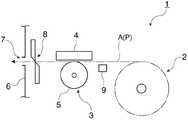
图1是表示本发明的实施方式涉及的热敏打印机的主要部分的概略构成的说明图。FIG. 1 is an explanatory diagram showing a schematic configuration of a main part of a thermal printer according to an embodiment of the present invention.
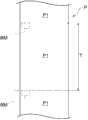
图2是记录纸的俯视图。Fig. 2 is a plan view of recording paper.
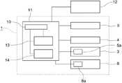
图3是表示热敏打印机的控制系统的概略框图。Fig. 3 is a schematic block diagram showing a control system of the thermal printer.
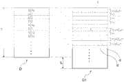
图4是表示输送量的校正方法的说明图。FIG. 4 is an explanatory diagram showing a method of correcting the transport amount.
图5是表示其他输送量的校正方法的说明图。FIG. 5 is an explanatory diagram showing another method of correcting the transport amount.
符号说明:Symbol Description:
1-热敏打印机(打印装置)、2-滚筒纸收容部、3-记录纸输送机构、4-热敏打印头(打印头)、5-压纸辊(送纸辊)、5a-输送电动机(驱动源)、6-打印机外壳、7-记录纸排出口、8-自动切割机、8a-切割机电动机、9-纸检测器、10-存储部、11-控制部、12-主机装置、13-滑动量计算部、14-输送量校正部、A-输送路径、B-打印位置、BM-黑色标记(标记)、C-检测位置、D-打印图像、D1-打印图像、d-非打印区域、ΔD-分割区域、ΔDa-空白区域、E-打印对象、L-滑动量、P-记录纸、P1-打印区域、T-排列间距。1-Thermal printer (printing device), 2-Roll paper storage unit, 3-Recording paper conveying mechanism, 4-Thermal print head (print head), 5-Press roller (feed roller), 5a-Conveying motor (drive source), 6-printer casing, 7-recording paper outlet, 8-automatic cutter, 8a-cutter motor, 9-paper detector, 10-storage unit, 11-control unit, 12-host device, 13-sliding amount calculation section, 14-transportation amount correction section, A-transportation path, B-printing position, BM-black mark (mark), C-detection position, D-printing image, D1-printing image, d-not Printing area, ΔD-division area, ΔDa-blank area, E-printing object, L-sliding amount, P-recording paper, P1-printing area, T-arrangement pitch.
具体实施方式Detailed ways
打印装置printing device
下面,参照附图说明适用本发明的实施方式。图1是表示本发明的实施方式涉及的热敏打印机的主要部分的概略构成的说明图。热敏打印机1(打印装置)具备:滚筒纸收容部2,其用于收容将长尺状记录纸P卷成滚筒状的滚筒纸;记录纸输送机构3,其沿着打印机内部的输送路径A输送从滚筒纸收容部2内的滚筒纸排出的记录纸P;和热敏打印头4(打印头),其面向发热部分配置在输送路径A上的打印位置B处。Embodiments to which the present invention is applied will be described below with reference to the drawings. FIG. 1 is an explanatory diagram showing a schematic configuration of a main part of a thermal printer according to an embodiment of the present invention. The thermal printer 1 (printing device) is equipped with: a roll
图2是记录纸P的俯视图。在本实施方式中,作为记录纸P而使用了长尺状的连续纸,且在记录纸P的表面设有感热显色层。在记录纸P的背面,沿着记录纸P的长边方向(输送方向)以一定间隔附有黑色标记BM(标记)。从各黑色标记BM到下一黑色标记BM为止的区域为一个打印区域P1。即、在记录纸P的表面,打印区域P1以一定的排列间距T排列成一列,在各打印区域P1的开头配置的黑色标记BM被用作表示各打印区域P1的开头(基准位置)的位置指标。FIG. 2 is a plan view of the recording paper P. As shown in FIG. In this embodiment, long continuous paper is used as the recording paper P, and the surface of the recording paper P is provided with a thermosensitive color-developing layer. On the back of the recording paper P, black marks BM (marks) are attached at regular intervals along the longitudinal direction of the recording paper P (transportation direction). The area from each black mark BM to the next black mark BM is one printing area P1. That is, on the surface of the recording paper P, the print areas P1 are arranged in a row at a constant pitch T, and the black mark BM arranged at the head of each print area P1 is used as a position indicating the head (reference position) of each print area P1. index.
如图1所示,记录纸输送机构3具备与热敏打印头4对置配置的压纸辊5(送纸辊)、驱动该压纸辊5的输送电动机5a(参照图3)等。从滚筒纸排出的记录纸P以通过热敏打印头4和压纸辊5之间的方式进行填装,且伴随与该记录纸P抵接的压纸辊5的转动输送记录纸P。在热敏打印头4中的与压纸辊5对置的部分设有在记录纸P的宽度方向上排列的多个发热元件。在热敏打印头4与压纸辊5之间夹持的记录纸P的表面压接各发热元件,如果在该状态下对各发热元件施加预定电压使其发热,则与各发热元件抵接的记录纸P的感热显色层的部分被加热而显色,从而在记录纸P的表面形成了打印点。As shown in FIG. 1 , the recording
通过与压纸辊5的送纸同步地驱动热敏打印头4,在通过打印位置B的记录纸P的表面依次形成打印点列,来进行打印。输送路径A的下游端延伸到设置于热敏打印机1的打印机外壳6处的记录纸排出口7为止。在记录纸排出口7的附近设有记录纸切断用的自动切割机8。在打印完成的打印区域P1被排出到记录纸排出口7外侧的状态下停止输送,在该状态下通过自动切割机8切断记录纸P,而发行打印完成的记录纸片。By driving the
在输送路径A中的打印位置B的上游侧,配置有用于对记录纸P的输送位置进行检测的纸检测器9。纸检测器9是具备与在输送路径A上的记录纸P的背面对峙地配置的发光元件、和用于对记录纸P的背面所反射的反射光进行检测的受光元件的反射型光传感器。基于设置于记录纸P背面处的黑色标记BM通过纸检测器9的检测位置C时受光元件的输出变化,能够检测黑色标记BM的通过。On the upstream side of the printing position B in the conveyance path A, a
控制系统Control System
图3是表示热敏打印机1的控制系统的概略框图。热敏打印机1的控制系统以具备CPU及ROM、RAM等存储部10的控制部11为中心构成。存储部10能够预先存储控制用的值或控制程序等。在控制部11的输出侧,经由未图示的打印头驱动器连接热敏打印头4,并且经由未图示的电动机驱动器连接记录纸输送机构3的输送电动机5a。此外,还经由未图示的电动机驱动器连接自动切割机8的切割机电动机8a。另外,在控制部11的输入侧,连接上述的纸检测器9,并且经由通信线路等连接主机装置12。FIG. 3 is a schematic block diagram showing a control system of the
控制部11基于从主机装置12接收到的打印数据或指令,执行在ROM内保存的控制程序,以控制热敏打印机1的各部的驱动,来执行记录纸P的输送与定位动作、打印动作等。在记录纸P的输送与定位动作中,控制部11经由电动机驱动器控制通过输送电动机5a驱动的压纸辊5对记录纸P的输送。此时,控制部11对输送电动机5a的驱动步数或者输出转动量等驱动量进行计数,并基于该计数值取得压纸辊5的转动量,以控制记录纸P的输送量。另外,在向记录纸P打印的打印动作中,控制部11进行记录纸P的输送控制并且经由打印头驱动器驱动热敏打印头4,且根据由主机装置12一侧提供的打印数据,在记录纸P的表面形成打印点的集合体即打印图像。进而,控制部11经由电动机驱动器驱动控制切割机电动机8a,以使自动切割机8对记录纸P进行切断动作。The
控制部11在记录纸输送机构3输送记录纸P的输送过程中监视纸检测器9的受光元件的输出变化,并且在黑色标记BM通过了输送路径A上的检测位置C的情况下检测出该情况。之后,基于黑色标记BM的通过检测的时刻和上述的输送电动机5a的驱动步数或转动量的计数值,取得记录纸P的输送位置。由此,能够将记录纸P的期望部位定位于打印位置B。The
控制部11具备滑动量计算部13,该滑动量计算部13执行计算打印时的记录纸P的输送动作中的记录纸P与压纸辊5之间的滑动量L(参照图4)的处理。滑动量计算部13自基于纸检测器9的检测输出检测到各黑色标记BM通过的时刻起开始累计输送电动机5a的驱动步数或输出转动量,求出直到检测出下一黑色标记BM的通过的时刻为止的累计值。并且,计算将该累计值和假设完全没有产生滑动时的单位步数或每单位转动量的记录纸P的输送量(单位输送量)相乘而得到的值(实际输送量)。从该值中减去黑色标记BM的排列间距T之后的值为滑动量L。滑动量计算部13通过读出预先存储于存储部10内的排列间距T的值,来计算对位于这两个黑色标记BM之间的打印区域P1进行打印时的滑动量L。The
另外,也可取代输送电动机5a的驱动量,由旋转编码器等直接取得压纸辊5的转动量,来计算滑动量L。另外,也可取代预先存储的排列间距T的值,将由打印数据指示的输送量的目标值(输送电动机5a的驱动量的设定值等)与实际驱动量的累计值或由该累计值计算出的实际输送量进行比较,来计算滑动量L。In addition, instead of the drive amount of the
算出的滑动量L存储到存储部10中,并在对下一打印区域进行校正时将其读出来进行使用。即便热敏打印机1的电源为OFF,由于滑动量L也存储于存储部10中,因此在电源变为ON之后,在对下一打印区域进行校正时能够将其读出来进行校正。The calculated slippage amount L is stored in the
另外,控制部11具备输送量校正部14,该输送量校正部14基于之前算出的滑动量L执行如下处理,即校正基于打印数据对各打印区域P1进行打印时的记录纸P的输送量。在产生滑动的情况下,如果在对各打印区域P进行打印时如打印数据指示的那样进行输送控制,则输送量会产生不足,不足量为滑动量L。因此,在本实施方式中,考虑上述情况,输送量校正部14按照将在对各打印区域P1进行打印的打印数据中所设定的记录纸P的输送量增大了刚算出的滑动量L的方式,变更打印时的处理内容。由此,在执行打印时,输送量的增大量(校正量)和滑动量L相互抵消,结果消除了由原始打印数据指示的输送量和实际输送量之间的误差。下面,对由输送量校正部14执行用的各种校正方法进行说明。Also, the
通过插入与滑动量相应的尺寸大小的非打印区域对输送量进行校正的校正方法Correction method for correcting the feed amount by inserting a non-printable area of a size corresponding to the slippage amount
图4是表示输送量的校正方法的说明图,图4A是一并插入非打印区域的校正方法的说明图,图4B是分割插入非打印区域的校正方法的说明图。在执行该校正方法时,首先前提是执行如下的处理:每当对各打印区域P进行打印时由滑动量计算部13计算滑动量L,并将算出的值存储并保持在存储部10中。被存储的滑动量L在每当通过下一次打印计算新滑动量L时被更新。4 is an explanatory diagram showing a method of correcting the transport amount, FIG. 4A is an explanatory diagram of a method of calibrating a non-printing area collectively, and FIG. 4B is an explanatory diagram of a calibrating method of dividing and inserting a non-printing area. When this correction method is executed, it is first assumed that the slip
一并插入非打印区域的校正方法Correction method of inserting non-printing area together
如图4A所示,在该校正方法中,按照由打印数据指示的内容,将对打印区域P1进行打印的原始打印图像D在图像缓冲区中展开之后,输送量校正部14进行如下校正:在该打印图像D的后端插入与在前一次打印中算出的滑动量L(从存储部10读出的滑动量L)相同长度的非打印区域d。该打印图像D的后端是通过热敏打印头4不进行打印的区域,即便插入非打印区域d也不会对打印图像D的打印结果产生影响。并且,按照从打印区域P1的开头起打印校正后的打印图像D1的方式控制热敏打印机1的各部分。As shown in FIG. 4A , in this correction method, after the original print image D for printing on the print area P1 is developed in the image buffer according to the content indicated by the print data, the transport
这样一来,从开始向打印区域P1打印到打印结束为止的记录纸P的输送量为在由原始打印数据指示的输送量上相加滑动量L而得到的长度。但是,在执行打印时实际输送的记录纸P的长度比所设定的输送量要短滑动量L的长度,结果能够输送由原始打印数据指示的尺寸大小的记录纸P。因此,能够全部消除直到打印结束时因滑动引起的输送误差,能够直接开始下一次打印。In this way, the transport amount of the recording paper P from the start of printing to the printing area P1 to the end of printing is the length obtained by adding the slip amount L to the transport amount indicated by the original print data. However, the length of the recording paper P actually conveyed when printing is executed is shorter than the set conveyance amount by the sliding amount L, and as a result, the recording paper P of the size indicated by the original print data can be conveyed. Therefore, it is possible to completely eliminate the conveyance error due to slipping until the end of printing, and it is possible to directly start the next printing.
这里,在图4A的例子中,虽然将非打印区域d的插入位置设置在打印图像D的后端,但也能将其插入到其他位置。例如,在页脚配置于打印图像D的后端的情况下,也可将非打印区域d插入到该页脚之前。这样一来,能够消除因滑动引起的页脚的打印位置的偏移。或者,在打印图像的前端配置页眉,然后配置文本或图像的情况下,也考虑将非打印区域d插入到页眉与文本或图像之间。除此之外,也可将非打印区域d一并插入到预先设定的各种位置来进行设定。另外,也可如后述那样在将标签纸用作记录纸P的情况下,插入到标签与标签之间的底纸位置。Here, in the example of FIG. 4A , although the insertion position of the non-printing area d is set at the rear end of the print image D, it can also be inserted at another position. For example, when the footer is arranged at the rear end of the print image D, the non-printing area d may be inserted before the footer. In this way, it is possible to eliminate the deviation of the print position of the footer due to sliding. Alternatively, when a header is arranged at the front end of an image to be printed, and then text or an image is arranged, it is also considered to insert a non-printable area d between the header and the text or image. In addition, it is also possible to insert the non-printing area d into various preset positions for setting. In addition, when label paper is used as the recording paper P as described later, it may be inserted at the position of the backing paper between the labels.
分割插入非打印区域的校正方法Correction method for dividing and inserting non-printing area
在图4B所示的校正方法中,根据由打印数据指示的内容将对打印区域P1进行打印的原始打印图像D在图像缓冲区中展开之后,输送量校正部14从开头朝向后端以预定的分割间距分割该打印图像D。由此,原始的打印图像D被分割到同一长度的多个分割区域ΔD中。接着,输送量校正部14判断在各分割区域ΔD内是否配置打印点(打印要素),检测未配置打印点的空白的分割区域ΔD、即空白区域ΔDa。之后,将非打印区域d插入到检测出的空白区域ΔDa中。例如,在原始打印图像D为文件的情况下,以行间距为单位分割打印图像D,将非打印区域d插入到空白行中。另外,也可以是行方向的文字与文字之间的空白区域。In the correction method shown in FIG. 4B , after the original print image D for printing the print area P1 is developed in the image buffer according to the content indicated by the print data, the conveyance
在图4B中,检测出有多个空白区域ΔDa,将分割了非打印区域d后的区域分散插入到这些所有的空白区域ΔDa中。输送量校正部14按如下方法向各空白区域ΔDa插入非打印区域d。首先,计算滑动量L除以分割区域ΔD的个数n而得到的值、即单位插入量L/n。其次,自打印区域P1的开头依次判断各分割区域ΔD是否是空白区域ΔDa。在开头的分割区域ΔD是空白区域ΔDa的情况下,将单位插入量L/n的长度的非打印区域d插入到该空白区域ΔDa中。由此,该空白区域ΔDa的长度仅延长单位插入量L/n,并且其后方的分割区域ΔD偏移到后方仅为单位插入量L/n的插入量。In FIG. 4B , a plurality of blank areas ΔDa are detected, and areas obtained by dividing the non-printing area d are scattered and inserted into all of these blank areas ΔDa. The transport
在开头的分割区域ΔD不是空白区域ΔDa的情况下,按照由打印数据指示的方式打印该分割区域ΔD,然后进入到下一分割区域ΔD的判断。之后,持续判断到出现空白区域ΔDa为止,不是空白区域ΔDa的分割区域ΔD原封不动。在出现了空白区域ΔDa的情况下,计算将前一个不是空白区域ΔDa的分割区域ΔD的连续数与单位插入量L/n相乘得到的长度,插入将该值与单位插入量L/n相加得到的长度的非打印区域d。If the first divisional area ΔD is not a blank area ΔDa, the divisional area ΔD is printed as indicated by the print data, and then proceeds to the determination of the next divisional area ΔD. Thereafter, the determination is continued until the blank area ΔDa appears, and the divided area ΔD that is not the blank area ΔDa remains unchanged. In the case where a blank area ΔDa appears, calculate the length obtained by multiplying the consecutive number of division areas ΔD that were not the previous blank area ΔDa by the unit insertion amount L/n, and insert this value to the unit insertion amount L/n. Add the resulting length of the non-printable area d.
在空白区域ΔDa的后一分割区域ΔD持续为空白区域ΔDa的情况下,在该连续的空白区域ΔDa中插入单位插入量L/n的长度的非打印区域d。另一方面,在空白区域ΔDa之后配置一个或连续配置预定数的分割区域ΔD,然后为空白区域ΔDa的情况下,如上述那样,计算将在该空白区域ΔDa的前一个不是空白区域ΔDa的分割区域ΔD的连续数与单位插入量L/n相乘得到的长度,插入将该值与单位插入量L/n相加得到的长度的非打印区域d。When the subsequent divided area ΔD of the blank area ΔDa continues to be the blank area ΔDa, a non-printing area d having a length of the unit insertion amount L/n is inserted into the continuous blank area ΔDa. On the other hand, when one or a predetermined number of divisional areas ΔD are arranged consecutively after the blank area ΔDa, and then there is a blank area ΔDa, as described above, the division that is not the blank area ΔDa before the blank area ΔDa is calculated. The length obtained by multiplying the continuous number of areas ΔD by the unit insertion amount L/n is inserted into a non-printing area d having a length obtained by adding this value to the unit insertion amount L/n.
也就是说,根据该插入方法,一旦出现空白区域ΔDa,原则上插入单位插入量L/n的非打印区域d,但是在不出现空白区域ΔDa的情况下,将非打印区域d的插入量每次累加单位插入量L/n直到出现空白区域ΔDa为止,留待直到出现空白区域ΔDa为止插入非打印区域d,一旦出现空白区域ΔDa就将累计量与单位插入量L/n相加起来一次全部插入。这样一来,大致沿着从打印区域P1的开头到后端的方向以一定的增加率逐渐增加非打印区域d的累计插入量。因此,不会对打印点的集合体产生影响,能够将非打印区域d适当分散地插入到打印图像中。由此,以打印图像为整体的话,能够扩大滑动量L的长度,能够消除输送误差。另外,不会在打印图像中形成白条等,能够抑制打印品质的降低。进而,如果增多分割数,则能够更精细地分散插入非打印区域d,因此对打印结果影响小,且可良好地观看。此外,也可将非打印区域d仅插入到空白区域ΔDa的一部分来设定。That is to say, according to this insertion method, once the blank area ΔDa appears, in principle, the non-printing area d of the unit insertion amount L/n is inserted, but in the case where the blank area ΔDa does not appear, the insertion amount of the non-printing area d is Accumulate the unit insertion amount L/n until the blank area ΔDa appears, and insert the non-printing area d until the blank area ΔDa appears. Once the blank area ΔDa appears, add the cumulative amount and the unit insertion amount L/n to insert all at once . In this way, the cumulative insertion amount of the non-printing area d is gradually increased at a constant rate approximately along the direction from the beginning to the rear end of the printing area P1. Therefore, it is possible to appropriately disperse and insert the non-printing area d into the printed image without affecting the aggregate of printed dots. Thereby, the length of the slippage L can be increased for the print image as a whole, and the conveyance error can be eliminated. In addition, no white streaks or the like are formed in the printed image, and it is possible to suppress a decrease in print quality. Furthermore, if the number of divisions is increased, the non-printing area d can be dispersed and inserted more finely, so that it has little influence on the printing result and can be viewed well. In addition, the non-printing area d may be set by inserting only a part of the blank area ΔDa.
根据滑动量对打印要素的展开位置进行坐标变换的输送量的校正方法Correction method of conveying amount by coordinate transformation of the developed position of print element based on slippage amount
图5是表示其他输送量的校正方法的说明图。在该校正方法中前提是每当对各打印区域P1进行打印时就更新校正用的滑动量L。另外,在该校正方法中前提是,在基于打印数据将打印图像在图像缓冲区中展开时,以文字、图像等打印对象为单位设定成为打印起点的坐标,并根据该坐标将各打印对象配置在打印区域P1上,并展开打印图像。这样,将图像缓冲区作为由坐标规定的一枚页面构成,将指定打印对象的坐标而配置的展开模式称为页面模式。与之相对,将如上述图4那样以行为单位展开打印图像的模式称为普通模式。FIG. 5 is an explanatory diagram showing another method of correcting the transport amount. The premise of this correction method is that the slippage amount L for correction is updated every time printing is performed on each print area P1. In addition, in this correction method, the premise is that when the print image is developed in the image buffer based on the print data, the coordinates of the print start point are set in units of print objects such as characters and images, and each print object is drawn based on the coordinates. Arranged on the print area P1, and expand the print image. In this way, the image buffer is constituted as one page defined by coordinates, and the expansion pattern that specifies the coordinates of the print object and is arranged is called a page pattern. On the other hand, the mode in which the print image is expanded in line units as in FIG. 4 described above is referred to as the normal mode.
图5A是按照原始打印数据展开了打印图像D状态下的说明图,图5B是展开了已校正的打印图像D1状态下的说明图。如图5A所示,构成原始打印图像D的打印对象E(E1、E2……En)配置于由打印数据指示的展开坐标(x1、y1)、(x2、y2)……(xn、yn)处。但是,当按照该打印图像D进行打印时,实际上整体上作为打印结果缩小了滑动量L的长度。此时,各打印对象E的实际打印坐标向按照因滑动引起的向记录纸输送方向的打印结果缩小的缩小率进行坐标变换的地方移动。记录纸输送方向的打印结果的缩小率是基于打印区域P1的排列间距T及滑动量,作为(T-L)/T而求出的。即、实际的各打印对象E的打印坐标为(x1、y1×(T-L)/T)、(x2、y2×(T-L)/T)……(xn、yn×(T-L)/T)。FIG. 5A is an explanatory diagram in a state where a print image D is expanded according to original print data, and FIG. 5B is an explanatory diagram in a state where a corrected print image D1 is expanded. As shown in FIG. 5A, the print objects E (E1, E2...En) constituting the original print image D are arranged at the development coordinates (x1, y1), (x2, y2)...(xn, yn) indicated by the print data. place. However, when printing is performed according to the print image D, the length of the sliding amount L is actually reduced as a whole as a result of printing. At this time, the actual printing coordinates of each printing object E move to a position where the coordinate conversion is carried out according to the reduction ratio of the reduction of the printing result in the recording paper conveyance direction due to slipping. The reduction rate of the printed result in the recording paper conveyance direction is obtained as (T-L)/T based on the arrangement pitch T and the slippage amount of the printing area P1. That is, the actual printing coordinates of each printing object E are (x1, y1×(T-L)/T), (x2, y2×(T-L)/T) . . . (xn, yn×(T-L)/T).
因此,输送量校正部14在因滑动缩小了打印图像时,校正各打印对象E的展开坐标使得结果与原始展开坐标(x1、y1)、(x2、y2)……(xn、yn)相一致。因此,例如,如图5B所示,执行将校正后的展开坐标中的y坐标(记录纸输送方向的坐标)设为缩小率的倒数倍的校正。校正后的展开坐标为(x1、y1×T/(T-L))、(x2、y2×T/(T-L))……(xn、yn×T/(T-L))。这样一来,作为打印结果,各打印对象E分别因滑动而打印到由打印数据指示的位置处。因此,结果能够按原始打印图像进行打印。由此,即便产生滑动,也能高精度地进行打印。Therefore, when the print image is reduced due to sliding, the transport
以上,根据上述的各校正方法,基于前一次打印中的滑动量L(输送距离的不足量)进行对记录纸P输送量进行了校正的打印处理,因此能够迅速地反馈记录纸输送机构3中的压纸辊5的磨损等状态变化,始终能够进行最适当的滑动校正。由此,能够抑制记录纸P的实际输送量和在打印数据中指示的输送量之间的偏移的产生,能够有效地抑制打印品质的下降。另外,由于用户无需手动地进行校正,因此不会给用户带来负担,能够维持高的打印品质。特别是,即便是条形码等要求高精度的打印,也能够维持高的打印品质,能够抑制条形码的读取品质的下降。As described above, according to each of the above-mentioned correction methods, the printing process for correcting the conveyance amount of the recording paper P is performed based on the slippage amount L (shortage of the conveyance distance) in the previous printing, so it is possible to promptly feed back Optimum slippage correction can always be performed in spite of state changes such as wear of the
另外,根据上述各校正方法,能够与输送电动机5a输送的输送量的控制间距无关地调整各打印要素的打印位置。因此,能够高精度地消除因滑动引起的打印位置的偏移,能够降低打印品质的下降。In addition, according to each of the correction methods described above, the printing position of each printing element can be adjusted regardless of the control pitch of the conveyance amount conveyed by the
变形例Variation
(1)上述各校正方法虽然采用了长尺状的连续纸作为记录纸P,但也适用于其他记录介质。例如,针对于在长尺状的底纸上以一定间距粘贴有感热纸标签的标签纸的底纸的背面附加成为各标签的位置基准的黑色标记BM的记录介质,也可进行同样的输送量的校正。另外,作为记录纸P也可采用预定长度的一定规格的纸而不是长尺状的连续纸。这种情况下,每当对一枚一定规格的纸进行打印时取得滑动量L,在向下一枚一定规格的纸打印时对输送量进行校正。由此,能够抑制向各一定规格的纸打印的打印品质的下降。(1) Although the above-mentioned correction methods use long continuous paper as the recording paper P, they are also applicable to other recording media. For example, the same conveyance can also be carried out for a recording medium in which a black mark BM is added as a positional reference for each label on the back of the backing paper of the label paper in which thermal paper labels are pasted at a certain interval on the long-shaped backing paper. Quantity correction. In addition, as the recording paper P, paper of a predetermined size and a predetermined length may be used instead of long continuous paper. In this case, the slippage amount L is acquired every time one sheet of paper of a certain specification is printed, and the conveyance amount is corrected when printing to the next sheet of paper of a certain specification. Accordingly, it is possible to suppress a decrease in print quality when printing on paper of each predetermined specification.
(2)在作为记录纸P而采用标签纸的情况下,作为纸检测器9能够使用透过型光传感器而不是反射型光传感器。这种情况下,由于通过检测标签的端部以取得输送位置,由此能够取得滑动量L,因此无需设置黑色标记BM。(2) When label paper is used as the recording paper P, a transmissive optical sensor instead of a reflective optical sensor can be used as the
(3)上述实施方式是将本发明适用于热敏打印机1的实施方式,但也能适用于采用喷墨式打印头的打印机中。这种情况下,能够基于在输送路径A的预定位置夹持记录纸P进行输送的送纸辊对的驱动辊的驱动量来取得滑动量L,并对输送量进行校正。(3) The above-mentioned embodiment is an embodiment in which the present invention is applied to the
Claims (18)
Translated fromChineseApplications Claiming Priority (2)
| Application Number | Priority Date | Filing Date | Title |
|---|---|---|---|
| JP2010-269071 | 2010-12-02 | ||
| JP2010269071AJP5803093B2 (en) | 2010-12-02 | 2010-12-02 | Printing apparatus and control method thereof |
Publications (2)
| Publication Number | Publication Date |
|---|---|
| CN102555549Atrue CN102555549A (en) | 2012-07-11 |
| CN102555549B CN102555549B (en) | 2014-11-05 |
Family
ID=46162361
Family Applications (1)
| Application Number | Title | Priority Date | Filing Date |
|---|---|---|---|
| CN201110389256.2AExpired - Fee RelatedCN102555549B (en) | 2010-12-02 | 2011-11-30 | Printing device and control method therefor |
Country Status (3)
| Country | Link |
|---|---|
| US (1) | US8780363B2 (en) |
| JP (1) | JP5803093B2 (en) |
| CN (1) | CN102555549B (en) |
Cited By (14)
| Publication number | Priority date | Publication date | Assignee | Title |
|---|---|---|---|---|
| CN103660623A (en)* | 2012-09-14 | 2014-03-26 | 佳能株式会社 | Conveyance apparatus and method for calculating conveyance correction value |
| CN103692786A (en)* | 2013-12-17 | 2014-04-02 | 重庆川仪自动化股份有限公司 | Curve printing control method and device applied to paper recording instrument |
| CN103921559A (en)* | 2013-01-10 | 2014-07-16 | 东芝泰格有限公司 | Thermal printer device |
| CN104275948A (en)* | 2013-07-04 | 2015-01-14 | 精工爱普生株式会社 | Printing device, printhead, and method of positioning print media in a printer |
| CN104442027A (en)* | 2013-09-13 | 2015-03-25 | 株式会社理光 | Image forming apparatus and roll print medium conveyance control method |
| CN106476429A (en)* | 2015-09-01 | 2017-03-08 | 精工爱普生株式会社 | The control method of printing equipment and printing equipment |
| CN105073433B (en)* | 2013-03-21 | 2017-03-15 | 精工爱普生株式会社 | Tape drum and tape printing apparatus |
| CN106696471A (en)* | 2015-07-21 | 2017-05-24 | 山东新北洋信息技术股份有限公司 | Printer and control method thereof |
| CN107284044A (en)* | 2017-06-28 | 2017-10-24 | 威海新北洋技术服务有限公司 | Label machine and label printing method |
| CN104249573B (en)* | 2013-06-27 | 2018-09-04 | 精工爱普生株式会社 | The control method of media processing apparatus, printing equipment and media processing apparatus |
| CN109901804A (en)* | 2019-03-12 | 2019-06-18 | 天津大学 | A method of automatically correcting the layout of prepress manuscripts |
| CN110978822A (en)* | 2019-11-19 | 2020-04-10 | 广州市三环永新科技有限公司 | Lottery printing method, lottery reader, lottery printing system and storage medium |
| CN115157886A (en)* | 2022-07-06 | 2022-10-11 | 上海商米科技集团股份有限公司 | Label paper printing method and label printer using same |
| CN115958893A (en)* | 2021-10-13 | 2023-04-14 | 精工爱普生株式会社 | Printing device and method for controlling the printing device |
Families Citing this family (6)
| Publication number | Priority date | Publication date | Assignee | Title |
|---|---|---|---|---|
| JP2013080051A (en)* | 2011-10-03 | 2013-05-02 | Fuji Xerox Co Ltd | Image forming device |
| JP2015044331A (en)* | 2013-08-28 | 2015-03-12 | カシオ計算機株式会社 | Label printer, printing method, and program |
| JP2016030424A (en)* | 2014-07-30 | 2016-03-07 | キヤノン株式会社 | Recording apparatus and recording control method |
| JP2017222084A (en)* | 2016-06-15 | 2017-12-21 | セイコーエプソン株式会社 | Printer and control method for the same |
| JP6834481B2 (en)* | 2016-12-28 | 2021-02-24 | マックス株式会社 | Printing device |
| CN113588357B (en)* | 2021-08-04 | 2024-05-03 | 上海中科新核智能科技有限公司 | Automatic paper feeding sampling and measuring device for radioactive aerosol |
Citations (9)
| Publication number | Priority date | Publication date | Assignee | Title |
|---|---|---|---|---|
| CN1143928A (en)* | 1994-11-29 | 1997-02-26 | 株式会社吉姆帝王 | tape printing device |
| US5841898A (en)* | 1994-09-16 | 1998-11-24 | Canon Information Systems Research Australia Pty Ltd. | Utilization of scanned images in an image compositing system |
| CN2581171Y (en)* | 2002-09-13 | 2003-10-22 | 孙志娟 | Cylinder variable printing device for multi-plicate tickets |
| JP2005193381A (en)* | 2003-12-26 | 2005-07-21 | Kyocera Mita Corp | Image forming apparatus |
| JP2006175733A (en)* | 2004-12-22 | 2006-07-06 | Noritsu Koki Co Ltd | Inkjet printer |
| JP2007052073A (en)* | 2005-08-15 | 2007-03-01 | Ricoh Co Ltd | Image forming apparatus, method for controlling image forming apparatus, program, and recording medium |
| CN1969533A (en)* | 2004-06-15 | 2007-05-23 | 松下电器产业株式会社 | Printer |
| CN1971438A (en)* | 2005-11-24 | 2007-05-30 | 富士施乐株式会社 | Image forming device and method of correcting image to be formed |
| US20070223022A1 (en)* | 2006-03-24 | 2007-09-27 | Takeshi Suzuki | Printing apparatus |
Family Cites Families (10)
| Publication number | Priority date | Publication date | Assignee | Title |
|---|---|---|---|---|
| JP2988308B2 (en)* | 1995-02-27 | 1999-12-13 | マックス株式会社 | Tape printer device |
| JP2944630B1 (en)* | 1998-05-07 | 1999-09-06 | 米沢日本電気株式会社 | Continuous paper printer |
| JP2000025288A (en) | 1998-07-10 | 2000-01-25 | Alps Electric Co Ltd | Printer and method for recording rear face therefor |
| JP3387853B2 (en)* | 1999-06-03 | 2003-03-17 | 日本電気株式会社 | Paper transport error correction method and apparatus |
| JP2001341900A (en) | 2000-05-31 | 2001-12-11 | Tohoku Ricoh Co Ltd | Printing device |
| JP3864692B2 (en) | 2000-10-13 | 2007-01-10 | セイコーエプソン株式会社 | Correction of the sub-scan feed amount according to the print medium |
| US7317553B2 (en) | 2000-09-27 | 2008-01-08 | Seiko Epson Corporation | Settings of sub-scan feed error and sub-scan feed amount suitable for printing medium |
| JP5009774B2 (en)* | 2007-12-26 | 2012-08-22 | 株式会社サトー知識財産研究所 | Printer |
| JP5120043B2 (en)* | 2008-04-17 | 2013-01-16 | セイコーエプソン株式会社 | Printer driver and print data printing method |
| JP2010221574A (en)* | 2009-03-24 | 2010-10-07 | Nec Infrontia Corp | Printer, printing position correction method, printing position correction program, and program recording medium |
- 2010
- 2010-12-02JPJP2010269071Apatent/JP5803093B2/ennot_activeExpired - Fee Related
- 2011
- 2011-10-31USUS13/285,287patent/US8780363B2/ennot_activeExpired - Fee Related
- 2011-11-30CNCN201110389256.2Apatent/CN102555549B/ennot_activeExpired - Fee Related
Patent Citations (9)
| Publication number | Priority date | Publication date | Assignee | Title |
|---|---|---|---|---|
| US5841898A (en)* | 1994-09-16 | 1998-11-24 | Canon Information Systems Research Australia Pty Ltd. | Utilization of scanned images in an image compositing system |
| CN1143928A (en)* | 1994-11-29 | 1997-02-26 | 株式会社吉姆帝王 | tape printing device |
| CN2581171Y (en)* | 2002-09-13 | 2003-10-22 | 孙志娟 | Cylinder variable printing device for multi-plicate tickets |
| JP2005193381A (en)* | 2003-12-26 | 2005-07-21 | Kyocera Mita Corp | Image forming apparatus |
| CN1969533A (en)* | 2004-06-15 | 2007-05-23 | 松下电器产业株式会社 | Printer |
| JP2006175733A (en)* | 2004-12-22 | 2006-07-06 | Noritsu Koki Co Ltd | Inkjet printer |
| JP2007052073A (en)* | 2005-08-15 | 2007-03-01 | Ricoh Co Ltd | Image forming apparatus, method for controlling image forming apparatus, program, and recording medium |
| CN1971438A (en)* | 2005-11-24 | 2007-05-30 | 富士施乐株式会社 | Image forming device and method of correcting image to be formed |
| US20070223022A1 (en)* | 2006-03-24 | 2007-09-27 | Takeshi Suzuki | Printing apparatus |
Cited By (21)
| Publication number | Priority date | Publication date | Assignee | Title |
|---|---|---|---|---|
| CN103660623B (en)* | 2012-09-14 | 2016-01-06 | 佳能株式会社 | The method of conveying equipment and calculating feed correction value |
| CN103660623A (en)* | 2012-09-14 | 2014-03-26 | 佳能株式会社 | Conveyance apparatus and method for calculating conveyance correction value |
| CN103921559A (en)* | 2013-01-10 | 2014-07-16 | 东芝泰格有限公司 | Thermal printer device |
| CN105073433B (en)* | 2013-03-21 | 2017-03-15 | 精工爱普生株式会社 | Tape drum and tape printing apparatus |
| CN104249573B (en)* | 2013-06-27 | 2018-09-04 | 精工爱普生株式会社 | The control method of media processing apparatus, printing equipment and media processing apparatus |
| CN104275948B (en)* | 2013-07-04 | 2017-07-28 | 精工爱普生株式会社 | The alignment method of printing equipment, print head and printing equipment |
| CN104275948A (en)* | 2013-07-04 | 2015-01-14 | 精工爱普生株式会社 | Printing device, printhead, and method of positioning print media in a printer |
| CN104442027A (en)* | 2013-09-13 | 2015-03-25 | 株式会社理光 | Image forming apparatus and roll print medium conveyance control method |
| CN103692786B (en)* | 2013-12-17 | 2016-04-20 | 重庆川仪自动化股份有限公司 | Be applied to curve printing control method and the device of paper recorder |
| CN103692786A (en)* | 2013-12-17 | 2014-04-02 | 重庆川仪自动化股份有限公司 | Curve printing control method and device applied to paper recording instrument |
| CN106696471A (en)* | 2015-07-21 | 2017-05-24 | 山东新北洋信息技术股份有限公司 | Printer and control method thereof |
| CN106476429B (en)* | 2015-09-01 | 2018-05-29 | 精工爱普生株式会社 | The control method and printing equipment of printing equipment |
| CN106476429A (en)* | 2015-09-01 | 2017-03-08 | 精工爱普生株式会社 | The control method of printing equipment and printing equipment |
| CN107284044A (en)* | 2017-06-28 | 2017-10-24 | 威海新北洋技术服务有限公司 | Label machine and label printing method |
| CN107284044B (en)* | 2017-06-28 | 2019-08-02 | 威海新北洋技术服务有限公司 | Label machine and label printing method |
| CN109901804A (en)* | 2019-03-12 | 2019-06-18 | 天津大学 | A method of automatically correcting the layout of prepress manuscripts |
| CN109901804B (en)* | 2019-03-12 | 2022-06-14 | 天津大学 | A method for automatically correcting the layout of prepress manuscripts |
| CN110978822A (en)* | 2019-11-19 | 2020-04-10 | 广州市三环永新科技有限公司 | Lottery printing method, lottery reader, lottery printing system and storage medium |
| CN115958893A (en)* | 2021-10-13 | 2023-04-14 | 精工爱普生株式会社 | Printing device and method for controlling the printing device |
| CN115157886A (en)* | 2022-07-06 | 2022-10-11 | 上海商米科技集团股份有限公司 | Label paper printing method and label printer using same |
| CN115157886B (en)* | 2022-07-06 | 2023-12-29 | 上海商米科技集团股份有限公司 | Label paper printing method and label printer using same |
Also Published As
| Publication number | Publication date |
|---|---|
| CN102555549B (en) | 2014-11-05 |
| US20120141185A1 (en) | 2012-06-07 |
| JP2012116133A (en) | 2012-06-21 |
| JP5803093B2 (en) | 2015-11-04 |
| US8780363B2 (en) | 2014-07-15 |
Similar Documents
| Publication | Publication Date | Title |
|---|---|---|
| CN102555549B (en) | Printing device and control method therefor | |
| US9126426B2 (en) | Transfer control method of continuous paper and printer | |
| EP2193923A1 (en) | Printing apparatus | |
| JP2012116133A5 (en) | ||
| CN103935139A (en) | Printer device and printing method | |
| CN100398332C (en) | Imaging device and correction method for correcting feed error value | |
| US20030107640A1 (en) | Printed medium with integral image locator and method | |
| EP0712728A2 (en) | Printing method and printer in which the method is used | |
| US6505906B1 (en) | Method of exercising nozzles of an inkjet printer and article | |
| JP2004276396A (en) | Cueing position shift correction amount calculation method and printing apparatus | |
| JP5009774B2 (en) | Printer | |
| JP2016034725A (en) | Label printer and method of controlling label printer | |
| JP2003260833A (en) | Cut position control device, recording device, and cut position adjusting method | |
| JP7403353B2 (en) | printing device | |
| JP4192734B2 (en) | Medium conveying apparatus and image forming apparatus having the same | |
| JP7559348B2 (en) | Image forming apparatus and conveying device | |
| JP2004142269A (en) | Recording device | |
| JP2010023387A (en) | Method for cutting recording paper in printer and printer | |
| JP2010017995A (en) | Inkjet printer | |
| JP2004050481A (en) | Ink jet recording apparatus and recording system | |
| JP2003320718A (en) | Recording apparatus and paper feed correction method | |
| JP2007090677A (en) | Printing start position setting method | |
| JP5917168B2 (en) | Recording device | |
| KR100612021B1 (en) | Printing control method and apparatus of inkjet printer | |
| JP2019048690A (en) | Printer and program |
Legal Events
| Date | Code | Title | Description |
|---|---|---|---|
| C06 | Publication | ||
| PB01 | Publication | ||
| C10 | Entry into substantive examination | ||
| SE01 | Entry into force of request for substantive examination | ||
| C14 | Grant of patent or utility model | ||
| GR01 | Patent grant | ||
| CF01 | Termination of patent right due to non-payment of annual fee | ||
| CF01 | Termination of patent right due to non-payment of annual fee | Granted publication date:20141105 Termination date:20211130 |