CN102553687A - Ballstone group dynamic distribution detection system and method - Google Patents
Ballstone group dynamic distribution detection system and methodDownload PDFInfo
- Publication number
- CN102553687A CN102553687ACN2012100046025ACN201210004602ACN102553687ACN 102553687 ACN102553687 ACN 102553687ACN 2012100046025 ACN2012100046025 ACN 2012100046025ACN 201210004602 ACN201210004602 ACN 201210004602ACN 102553687 ACN102553687 ACN 102553687A
- Authority
- CN
- China
- Prior art keywords
- ball
- iron core
- ball mill
- main body
- carbon brush
- Prior art date
- Legal status (The legal status is an assumption and is not a legal conclusion. Google has not performed a legal analysis and makes no representation as to the accuracy of the status listed.)
- Granted
Links
- 238000001514detection methodMethods0.000titleclaimsabstractdescription120
- 238000009826distributionMethods0.000titleclaimsabstractdescription50
- 238000000034methodMethods0.000titleclaimsdescription14
- 239000004575stoneSubstances0.000claimsabstractdescription130
- XEEYBQQBJWHFJM-UHFFFAOYSA-NIronChemical group[Fe]XEEYBQQBJWHFJM-UHFFFAOYSA-N0.000claimsdescription120
- OKTJSMMVPCPJKN-UHFFFAOYSA-NCarbonChemical compound[C]OKTJSMMVPCPJKN-UHFFFAOYSA-N0.000claimsdescription72
- 229910052799carbonInorganic materials0.000claimsdescription72
- 230000006698inductionEffects0.000claimsdescription50
- 230000004907fluxEffects0.000claimsdescription32
- 238000009434installationMethods0.000claimsdescription22
- 229910000976Electrical steelInorganic materials0.000claimsdescription18
- 238000002955isolationMethods0.000claimsdescription12
- 230000008859changeEffects0.000claimsdescription7
- 239000000696magnetic materialSubstances0.000claimsdescription5
- 230000008569processEffects0.000claimsdescription5
- 229910052742ironInorganic materials0.000claimsdescription2
- 238000000227grindingMethods0.000abstractdescription4
- 238000010586diagramMethods0.000description18
- 239000002994raw materialSubstances0.000description5
- XLYOFNOQVPJJNP-UHFFFAOYSA-NwaterSubstancesOXLYOFNOQVPJJNP-UHFFFAOYSA-N0.000description3
- 239000010419fine particleSubstances0.000description2
- 229910052755nonmetalInorganic materials0.000description2
- 230000003068static effectEffects0.000description2
- 230000009286beneficial effectEffects0.000description1
- 230000001276controlling effectEffects0.000description1
- 238000009795derivationMethods0.000description1
- 230000000694effectsEffects0.000description1
- 238000009776industrial productionMethods0.000description1
- 238000004519manufacturing processMethods0.000description1
- 239000000203mixtureSubstances0.000description1
- 230000001105regulatory effectEffects0.000description1
- 238000004088simulationMethods0.000description1
- 239000007787solidSubstances0.000description1
Images


Landscapes
- Measurement Of Length, Angles, Or The Like Using Electric Or Magnetic Means (AREA)
- Crushing And Grinding (AREA)
Abstract
Translated fromChinese
Description
Translated fromChinese技术领域technical field
本发明涉及磨细工程机械领域,具体涉及一种球磨机球石群检测系统和方法。The invention relates to the field of grinding engineering machinery, in particular to a ball mill ball stone group detection system and method.
背景技术Background technique
球磨机是原料被破碎之后,再进行粉碎研磨的关键设备,是工业生产企业中最重要的高细磨生产设备。在球磨机内部,是球石、原料、水的混合物,在球磨机不断工作进程中,随着原料细度的增加,原料与水的混合程度也越来越充分,越来越多的固体原料被研磨成细小的颗粒,细小的颗粒越来越多的悬浮在水里,构成泥浆。The ball mill is the key equipment for crushing and grinding after the raw materials are crushed. It is the most important high-fine grinding production equipment in industrial production enterprises. Inside the ball mill is a mixture of ball stones, raw materials, and water. During the continuous working process of the ball mill, as the fineness of raw materials increases, the degree of mixing of raw materials and water becomes more and more sufficient, and more and more solid raw materials are ground. into fine particles, and more and more fine particles are suspended in the water to form mud.
在球磨机工作过程中,球石群分布直接影响了球磨机的工作效率。由于球磨机内部复杂的工作状况,导致球磨机内部球石群分布难以判断,难以描述。目前各研究机构都是以模拟方法、理论推导方法等方式进行推理研究,这与球石群分布、运行状况相差很多。During the working process of the ball mill, the distribution of the ball stone group directly affects the working efficiency of the ball mill. Due to the complex working conditions inside the ball mill, it is difficult to judge and describe the distribution of ball stone groups inside the ball mill. At present, various research institutions are conducting reasoning research by means of simulation methods and theoretical derivation methods, which are quite different from the distribution and operation status of ball stone groups.
发明内容Contents of the invention
本发明的目的在于,提供一种球石群动态分布检测系统,解决以上技术问题。The object of the present invention is to provide a ball stone group dynamic distribution detection system to solve the above technical problems.
本发明的另一目的在于,提供一种球石群动态分布检测方法,解决以上技术问题。Another object of the present invention is to provide a method for detecting the dynamic distribution of ball stone groups to solve the above technical problems.
本发明所解决的技术问题可以采用以下技术方案来实现:The technical problem solved by the present invention can adopt following technical scheme to realize:
球石群动态分布检测系统,包括一球磨机主体,所述球磨机主体通过一皮带连接一球磨电动机,所述球磨机主体上设有一球磨机盖,所述球磨机主体内设有球石群,其特征在于,所述球磨机盖上设有一球石群检测装置,所述球石群检测装置包括一电机,所述电机的输出轴连接一连杆的一端,所述连杆的另一端连接一动铁芯,所述连杆上固定有第一导电环、第二导电环、第三导电环、第四导电环;The dynamic distribution detection system of ball and stone groups includes a ball mill main body, the ball mill main body is connected with a ball mill motor through a belt, a ball mill cover is arranged on the ball mill main body, and ball stone groups are arranged in the ball mill main body, and the characteristics of the ball mill are: The ball mill cover is provided with a ball stone group detection device, the ball stone group detection device includes a motor, the output shaft of the motor is connected to one end of a connecting rod, and the other end of the connecting rod is connected to a moving iron core. A first conductive ring, a second conductive ring, a third conductive ring, and a fourth conductive ring are fixed on the connecting rod;
所述动铁芯上固定有线圈和感应线圈,所述线圈的两引出端分别连接所述第一导电环和所述第二导电环,所述感应线圈的两引出端分别连接所述第三导电环和所述第四导电环;A coil and an induction coil are fixed on the moving iron core, and the two leading ends of the coil are respectively connected to the first conductive ring and the second conductive ring, and the two leading ends of the induction coil are connected to the third conductive ring respectively. a conductive ring and the fourth conductive ring;
所述球磨机盖上分别固定有第一导电碳刷、第二导电碳刷、第三导电碳刷、第四导电碳刷,所述第一导电碳刷设置在所述第一导电环的一侧,所述第二导电碳刷设置在所述第二导电环的一侧,所述第三导电碳刷设置在所述第三导电环的一侧,所述第四导电碳刷设置在所述第四导电环的一侧;所述第一导电碳刷活动连接所述第一导电环,所述第二导电碳刷活动连接所述第二导电环,所述第三导电碳刷活动连接所述第三导电环,所述第四导电碳刷活动连接所述第四导电环;The first conductive carbon brush, the second conductive carbon brush, the third conductive carbon brush, and the fourth conductive carbon brush are respectively fixed on the ball mill cover, and the first conductive carbon brush is arranged on one side of the first conductive ring , the second conductive carbon brush is arranged on one side of the second conductive ring, the third conductive carbon brush is arranged on one side of the third conductive ring, and the fourth conductive carbon brush is arranged on the One side of the fourth conductive ring; the first conductive carbon brush is movably connected to the first conductive ring, the second conductive carbon brush is movably connected to the second conductive ring, and the third conductive carbon brush is movably connected to the The third conductive ring, the fourth conductive carbon brush is movably connected to the fourth conductive ring;
所述球石群检测装置还包括一电源模块,所述电源模块的电源输出端分别连接所述电机的输入端、所述第一导电碳刷、所述第二导电碳刷;The ball stone group detection device also includes a power module, the power output end of the power module is respectively connected to the input end of the motor, the first conductive carbon brush, and the second conductive carbon brush;
所述球石群检测装置还包括一电压检测传感器,所述第三导电碳刷、所述第四导电碳刷分别连接所述电压检测传感器的输入端,所述电压检测传感器的信号输出端连接一信号处理模块;The ball stone group detection device also includes a voltage detection sensor, the third conductive carbon brush and the fourth conductive carbon brush are respectively connected to the input end of the voltage detection sensor, and the signal output end of the voltage detection sensor is connected to a signal processing module;
所述球石群检测装置还包括一检测头,所述球磨机盖上设有一与球磨机主体内联通的开孔,所述检测头的一端伸出于开孔,与所述球磨机主体内联通,与所述球磨机主体内的球石群接触;所述检测头的另一端固定有随动铁芯,所述随动铁芯设置在所述动铁芯的下方,并存在一定的气隙,所述随动铁芯能随着所述动铁芯的转动而转动。The ball stone group detection device also includes a detection head, the ball mill cover is provided with an opening communicating with the ball mill main body, one end of the detection head protrudes from the opening, communicates with the ball mill main body, and communicates with the ball mill main body. The ball stone group in the main body of the ball mill is in contact; the other end of the detection head is fixed with a follower iron core, and the follower iron core is arranged below the move iron core, and there is a certain air gap. The moving iron core can rotate along with the rotation of the moving iron core.
本发明可以能检测球石群动态分布,检测原理如下:电机在电源模块的驱动下,按一定频率f匀速转动,带动连杆、固定在连杆上的第一导电环、第二导电环、第三导电环、第四导电环、线圈、感应线圈、动铁芯一起转动。线圈通入电源后,在动铁芯内部产生磁通,由动铁芯、气隙、随动铁芯构成磁通回路。The present invention can detect the dynamic distribution of ball stone groups, and the detection principle is as follows: under the drive of the power module, the motor rotates at a constant speed at a certain frequency f, driving the connecting rod, the first conductive ring fixed on the connecting rod, the second conductive ring, The third conductive ring, the fourth conductive ring, the coil, the induction coil and the moving iron core rotate together. After the coil is connected to the power supply, a magnetic flux is generated inside the moving iron core, and the magnetic flux circuit is formed by the moving iron core, the air gap, and the moving iron core.
在球磨机主体内部没有球石群时,检测头伸出部分没有被阻碍,电机带动动铁芯转动,动铁芯内部的磁场带动随动铁芯自由转动,动铁芯的硅钢片安装方向和和随动铁芯的硅钢片安装方向保持一致,磁通回路稳定,磁阻稳定,磁通量恒定,感应线圈上没有感应电势产生。When there is no ball stone group inside the main body of the ball mill, the protruding part of the detection head is not blocked, the motor drives the moving iron core to rotate, and the magnetic field inside the moving iron core drives the follower iron core to rotate freely. The installation direction of the silicon steel sheet of the moving iron core and The installation direction of the silicon steel sheet of the follower iron core is consistent, the magnetic flux circuit is stable, the reluctance is stable, the magnetic flux is constant, and there is no induced potential on the induction coil.
当球磨机主体内部有球石群时,检测头伸出部分被阻碍,检测头与随动铁芯不能自由转动;电机带动动铁芯转动,动铁芯内部的磁场不能带动随动铁芯自由转动。此时,动铁芯的硅钢片安装方向偏离随动铁芯的硅钢片安装方向,磁通回路磁阻变大,当动铁芯的硅钢片安装方向和随动铁芯的硅钢片安装方向垂直时,磁通回路磁阻最大;在随动铁芯随同检测头被球石群阻碍时,电机在电源模块驱动下还是按一定频率f匀速转动,动铁芯按频率f匀速转动,磁通回路磁阻大小变化也按频率f有规律的变动,在电源模块电压稳定的情况下,动铁芯内部的磁通量大小也会有规律的变化,在感应线圈上就会感应出按频率f变化的感应电动势,电压检测传感器检测这个按频率f变化的感应电动势,并输出到信号处理模块,依据感应电动势存在时间及电机转动时间,可以判断球磨机主体内部的球石群存在状态、分布状态。When there is a group of ball stones inside the main body of the ball mill, the protruding part of the detection head is blocked, and the detection head and the follow-up iron core cannot rotate freely; the motor drives the move iron core to rotate, and the magnetic field inside the move iron core cannot drive the follow-up iron core to rotate freely . At this time, the installation direction of the silicon steel sheet of the moving iron core deviates from the installation direction of the silicon steel sheet of the follower iron core, and the reluctance of the magnetic flux circuit becomes larger. , the magnetic resistance of the magnetic flux circuit is the largest; when the moving iron core and the detection head are obstructed by the ball stone group, the motor still rotates at a constant speed at a certain frequency f under the drive of the power module, and the moving iron core rotates at a constant speed at a frequency f, and the magnetic flux circuit The change of the reluctance also changes regularly according to the frequency f. When the voltage of the power module is stable, the magnetic flux inside the moving iron core will also change regularly, and the induction coil will induce an induction that changes according to the frequency f. Electromotive force, the voltage detection sensor detects the induced electromotive force that changes according to the frequency f, and outputs it to the signal processing module. According to the existence time of the induced electromotive force and the rotation time of the motor, the existence state and distribution state of the ball stone group inside the main body of the ball mill can be judged.
所述电机设置在所述球磨机盖上,所述连杆设置在所述电机输出轴下方,所述动铁芯设置在所述连杆的底部,所述随动铁芯设置在所述动铁芯下方。The motor is arranged on the ball mill cover, the connecting rod is arranged under the output shaft of the motor, the moving iron core is arranged at the bottom of the connecting rod, and the moving iron core is arranged on the moving iron below the core.
所述动铁芯和所述随动铁芯之间设有一隔离盖,所述隔离盖采用非金属、非导磁材料制成。An isolation cover is provided between the moving iron core and the moving iron core, and the isolation cover is made of non-metal and non-magnetic material.
所述检测头呈T字型结构,所述检测头的中部呈圆柱形,圆柱形的检测头内嵌在所述球磨机盖内侧,并与所述球磨机主体内部联通。The detection head has a T-shaped structure, and the middle part of the detection head is cylindrical. The cylindrical detection head is embedded inside the ball mill cover and communicates with the inside of the ball mill main body.
所述信号处理模块通过无线的方式连接外部手持无线接收设备,所述手持无线接收设备连接一显示系统。使用者可以通过手持手持无线接收设备,查看显示系统,了解球磨机主体内球石群分布情况、球磨机主体的工作状态、球磨电动机的转速等信息。The signal processing module is wirelessly connected to an external handheld wireless receiving device, and the handheld wireless receiving device is connected to a display system. The user can check the display system by holding the handheld wireless receiving device to understand the distribution of ball stone groups in the main body of the ball mill, the working status of the main body of the ball mill, the speed of the ball mill motor and other information.
球石群动态分布检测方法,其特征在于,包括如下步骤:The ball stone group dynamic distribution detection method is characterized in that it comprises the following steps:
1)设备安装:在球磨机主体正常工作前,将球石群检测装置设置在球磨机主体的球磨机盖上,球磨机盖上设有与球磨机主体内联通的开孔,球石群检测装置的检测头一端伸出于开孔,与所述球磨机主体内球石群接触,启动球石群检测装置的电源模块;1) Equipment installation: Before the main body of the ball mill works normally, install the ball stone group detection device on the ball mill cover of the ball mill main body. The ball mill cover is provided with an opening communicating with the ball mill main body. protruding from the opening, contacting the ball stone group in the main body of the ball mill, and starting the power module of the ball stone group detection device;
2)信号采集:球磨机主体正常工作时,信号处理模块通过球石群检测装置实时采集检测头被球石群阻碍时产生的感应信号;2) Signal acquisition: when the main body of the ball mill is working normally, the signal processing module collects the induction signal generated when the detection head is blocked by the ball stone group in real time through the ball stone group detection device;
信号处理模块采集球磨机主体的转速信号;The signal processing module collects the rotational speed signal of the main body of the ball mill;
3)确定球石群分布情况:信号处理模块对转速信号和感应信号进行处理,通过球磨机主体转动一周内,感应信号的情况,判断球石群分布情况。3) Determine the distribution of the ball stone group: the signal processing module processes the speed signal and the induction signal, and judges the distribution of the ball stone group according to the situation of the induction signal within one rotation of the main body of the ball mill.
所述球石群检测装置包括一电机,所述电机的输出轴连接一连杆的一端,所述连杆的另一端连接一动铁芯,所述连杆上固定有第一导电环、第二导电环、第三导电环、第四导电环;The ball stone group detection device includes a motor, the output shaft of the motor is connected to one end of a connecting rod, the other end of the connecting rod is connected to a moving iron core, and the connecting rod is fixed with a first conductive ring, a second Conductive ring, third conductive ring, fourth conductive ring;
所述动铁芯的一边固定有线圈,所述动铁芯的另一边固定有感应线圈,所述线圈的两引出端分别连接所述第一导电环和所述第二导电环,所述感应线圈的两引出端分别连接所述第三导电环和所述第四导电环;One side of the moving iron core is fixed with a coil, and the other side of the moving iron core is fixed with an induction coil, and the two leading ends of the coil are respectively connected to the first conductive ring and the second conductive ring, and the induction coil The two lead ends of the coil are respectively connected to the third conductive ring and the fourth conductive ring;
所述球磨机盖上分别固定有第一导电碳刷、第二导电碳刷、第三导电碳刷、第四导电碳刷,所述第一导电碳刷设置在所述第一导电环的一侧,所述第二导电碳刷设置在所述第二导电环的一侧,所述第三导电碳刷设置在所述第三导电环的一侧,所述第四导电碳刷设置在所述第四导电环的一侧;The first conductive carbon brush, the second conductive carbon brush, the third conductive carbon brush, and the fourth conductive carbon brush are respectively fixed on the ball mill cover, and the first conductive carbon brush is arranged on one side of the first conductive ring , the second conductive carbon brush is arranged on one side of the second conductive ring, the third conductive carbon brush is arranged on one side of the third conductive ring, and the fourth conductive carbon brush is arranged on the one side of the fourth conductive ring;
所述电源模块的电源输出端分别连接所述电机的输入端、所述第一导电碳刷、所述第二导电碳刷;The power output end of the power module is respectively connected to the input end of the motor, the first conductive carbon brush, and the second conductive carbon brush;
所述球石群检测装置还包括一电压检测传感器,所述第三导电碳刷、所述第四导电碳刷分别连接所述电压检测传感器的输入端,所述电压检测传感器的信号输出端连接所述信号处理模块;The ball stone group detection device also includes a voltage detection sensor, the third conductive carbon brush and the fourth conductive carbon brush are respectively connected to the input end of the voltage detection sensor, and the signal output end of the voltage detection sensor is connected to The signal processing module;
所述检测头的另一端固定有随动铁芯,所述随动铁芯设置在所述动铁芯的下方,并存在一定的气隙,所述随动铁芯随着所述动铁芯的转动而转动。The other end of the detection head is fixed with a follower iron core, the follower iron core is arranged below the mover iron core, and there is a certain air gap, and the follower iron core follows the mover iron core rotate and rotate.
所述动铁芯和所述随动铁芯之间设有一隔离盖,所述隔离盖采用非金属、非导磁材料制成。An isolation cover is provided between the moving iron core and the moving iron core, and the isolation cover is made of non-metal and non-magnetic material.
有益效果:由于采用上述技术方案,本发明克服了目前研究机构所描述的球石群分布不准确的缺点,实现了球石群分布的实际检测,且检测精度高。Beneficial effects: due to the adoption of the above technical solution, the present invention overcomes the shortcoming of inaccurate distribution of ball stone groups described by current research institutes, and realizes the actual detection of ball stone group distribution with high detection accuracy.
附图说明Description of drawings
图1为本发明球石群检测装置的整体结构示意图;Fig. 1 is the overall structure schematic diagram of ball stone group detection device of the present invention;
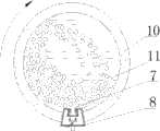
图2为本发明球磨机主体静态示意图;Fig. 2 is a static schematic diagram of the main body of the ball mill of the present invention;
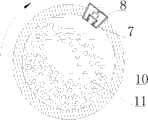
图3为本发明球磨机主体在转动状态下检测少量球石群分布状态图;Fig. 3 is a distribution state diagram of a small amount of ball stones detected by the main body of the ball mill of the present invention in a rotating state;
图4为本发明球磨机主体在转动状态下球石群检测装置在球石群分布范围内的状态图;Fig. 4 is a state diagram of the ball stone group detection device within the distribution range of the ball stone group when the main body of the ball mill of the present invention is in a rotating state;
图5为本发明球磨机主体在转动状态下球石群检测装置在球石群分布范围外的状态图;Fig. 5 is a state diagram of the ball stone group detection device outside the distribution range of the ball stone group when the main body of the ball mill of the present invention is in a rotating state;
图6为本发明球石群检测装置在球磨机主体内部没有球石群的状态图;Fig. 6 is a state diagram of the ball stone group detection device of the present invention without ball stone groups inside the main body of the ball mill;
图7为本发明球磨机主体内部球石群处于离心状态时的球石群分布状态图;Fig. 7 is a distribution state diagram of ball stone groups inside the main body of the ball mill of the present invention when the ball stone groups are in a centrifugal state;
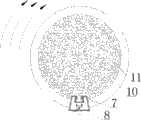
图8为本发明球磨机主体内部球石群处于装满状态时的球石群分布状况图;Fig. 8 is a diagram showing the distribution of ball stone groups inside the main body of the ball mill of the present invention when the ball stone groups are in a full state;
图9为本发明球磨机主体正常工作时各参数的波形图。Fig. 9 is a waveform diagram of various parameters when the main body of the ball mill of the present invention is in normal operation.
具体实施方式Detailed ways
为了使本发明实现的技术手段、创作特征、达成目的与功效易于明白了解,下面结合具体图示进一步阐述本发明。In order to make the technical means, creative features, goals and effects achieved by the present invention easy to understand, the present invention will be further described below in conjunction with specific diagrams.
参照图1、图2,球石群动态分布检测系统,包括一球磨机主体10,球磨机主体10通过一皮带连接一球磨电动机。球磨机主体10上设有一球磨机盖8,球磨机主体10内设有球石群11,球磨机盖8上设有一球石群检测装置,球石群检测装置包括一电机1,电机1的输出轴连接一连杆12的一端,连杆12的另一端连接一动铁芯4,连杆12上固定有第一导电环2、第二导电环13、第三导电环19、第四导电环21。Referring to Fig. 1 and Fig. 2, the system for detecting the dynamic distribution of ball stone groups includes a ball mill
动铁芯4的一边固定有线圈5,动铁芯4的另一边固定有感应线圈18,线圈5的两引出端分别连接第一导电环2和第二导电环13,感应线圈18的两引出端分别连接第三导电环19和第四导电环21。One side of the moving
球磨机盖8分别固定安装有第一导电碳刷3、第二导电碳刷14、第三导电碳刷20、第四导电碳刷22,第一导电碳刷3设置在第一导电环2的一侧,第二导电碳刷14设置在第二导电环13的一侧,第三导电碳刷20设置在第三导电环19的一侧,第四导电碳刷22设置在第四导电环21的一侧。第一导电碳刷3活动连接第一导电环2,第二导电碳刷14活动连接第二导电环13,第三导电碳刷20活动连接第三导电环19,第四导电碳刷22活动连接第四导电环21。The
球石群检测装置还包括一电源模块16,电源模块16的电源输出端分别连接电机1的输入端、第一导电碳刷3、第二导电碳刷14。The ball stone group detection device also includes a
球石群检测装置还包括一电压检测传感器15,第三导电碳刷20、第四导电碳刷22分别连接电压检测传感器15的输入端,电压检测传感器15的信号输出端连接一信号处理模块17。The ball stone group detection device also includes a
球石群检测装置还包括一检测头7,球磨机盖8上设有一与球磨机主体10内联通的开孔,检测头7的一端伸出于开孔,与球磨机主体10内联通,与球磨机主体10内的球石群11接触。检测头7的另一端固定有随动铁芯6,随动铁芯6设置在动铁芯4的下方,并存在一定的气隙,随动铁芯6随着动铁芯4的转动而转动。The ball stone group detection device also includes a
电机1竖直设置在球磨机盖8上,连杆12竖直设置在电机1输出轴下方,动铁芯4设置在连杆12的底部,随动铁芯6设置在动铁芯4下方。动铁芯4和随动铁芯6之间设有隔离盖9,隔离盖9采用非金属、非导磁材料制成。检测头7呈T字型结构,检测头7的中部呈圆柱形,圆柱形的检测头7内嵌在球磨机盖8内侧,并与球磨机主体10内部联通。The
本发明可以能检测球石群11动态分布,检测原理如下:电机1在电源模块16的驱动下,按一定频率f匀速转动,带动连杆12、固定在连杆12上的第一导电环2、第二导电环13、第三导电环19、第四导电环21、线圈5、感应线圈18、动铁芯4一起转动。线圈5通入电源后,在动铁芯4内部产生磁通,由动铁芯4、气隙、随动铁芯6构成磁通回路。The present invention can detect the dynamic distribution of the
在球磨机主体10内部没有球石群11时,检测头7伸出部分没有被阻碍,电机1带动动铁芯4转动,动铁芯4内部的磁场带动随动铁芯6自由转动,动铁芯4的硅钢片安装方向和和随动铁芯6的硅钢片安装方向保持一致,磁通回路稳定,磁阻稳定,磁通量恒定,感应线圈18上没有感应电势产生。When there is no
当球磨机主体10内部有球石群11时,检测头7伸出部分被阻碍,检测头7与随动铁芯6不能自由转动;电机1带动动铁芯4转动,动铁芯4内部的磁场不能带动随动铁芯6自由转动。此时,动铁芯4的硅钢片安装方向偏离随动铁芯6的硅钢片安装方向,磁通回路磁阻变大,当动铁芯4的硅钢片安装方向和随动铁芯6的硅钢片安装方向垂直时,磁通回路磁阻最大;在随动铁芯6随同检测头7被球石群11阻碍时,电机1在电源模块16驱动下还是按一定频率f匀速转动,动铁芯4按频率f匀速转动,磁通回路磁阻大小变化也按频率f有规律的变动,在电源模块16电压稳定的情况下,动铁芯4内部的磁通量大小也会有规律的变化,在感应线圈18上就会感应出按频率f变化的感应电动势,电压检测传感器15检测这个按频率f变化的感应电动势,并输出到信号处理模块17,依据感应电动势存在时间及电机1转动时间,可以判断球磨机主体10内部的球石群11存在状态、分布状态。When there is a
信号处理模块17通过无线的方式连接外部手持无线接收设备,手持无线接收设备连接一显示系统。使用者可以通过手持手持无线接收设备,查看显示系统,了解球磨机主体10内球石群分布情况、球磨机主体的工作状态、球磨电动机的转速等信息。The
参照图2,球磨机主体10处于静态状态时,检测头7没有受到球石群11的阻碍,感应线圈18上感应电动势为0。Referring to FIG. 2 , when the ball mill
参照图6,球磨机主体10正常工作时,在球磨机主体10转动一周过程中,检测头7没有受到球石群11的阻碍,感应线圈18上感应电动势为0,球磨机主体10内没有球石群。Referring to FIG. 6 , when the ball mill
参照图3、图4、图5,球磨机主体10正常工作时,在球磨机主体10转动一周过程中,感应线圈18上的感应电动势一会为0,一会不为0,说明球磨机主体10内部存在球石群11;依据球磨机主体10转动一周的时间及感应线圈18上感应电动势存在的时间,信号处理模块17可以判断球石群11在球磨机主体10内部的分布状况。Referring to Fig. 3, Fig. 4 and Fig. 5, when the ball mill
参照图7,球磨机主体10正常工作时,在球磨机主体10转动一周过程中,感应线圈18上的感应电动势始终存在,说明球磨机主体10的转速过高,球磨群11处于离心状态;参照图8,球磨机主体10正常工作时,在球磨机主体10转动一周过程中,感应线圈18上的感应电动势始终存在,球磨机主体10内部充满了球石群11。此时信号处理模块17可以通过控制调速装置,调节球磨电动机的转速,以便降低球磨机主体10的转速。Referring to Figure 7, when the ball mill
球石群动态分布检测方法,包括如下步骤:The method for detecting the dynamic distribution of ball stone groups comprises the following steps:
1)设备安装:在球磨机主体10正常工作前,将上述的球石群检测装置设置在球磨机主体10的球磨机盖8上,球磨机盖8上设有与球磨机主体10内联通的开孔,球石群检测装置的检测头7一端伸出于开孔,与球磨机主体10内球石群11接触,启动球石群检测装置的电源模块16。1) Equipment installation: before the ball mill
2)信号采集:球磨机主体10正常工作时,信号处理模块17通过球石群检测装置实时采集检测头7被球石群11阻碍时产生的感应信号,信号处理模块17采集球磨机主体10的转速信号。2) Signal acquisition: when the ball mill
3)确定球石群分布情况:信号处理模块17对转速信号和感应信号进行处理,通过球磨机主体10转动一周内,感应信号的情况,判断球石群分布情况。3) Determining the distribution of ball stone groups: the
信号处理模块根据如下原理判断球石群分布情况:线圈5通入电源后,在动铁芯4内部产生磁通,由动铁芯4、气隙、隔离盖9、随动铁芯6构成磁通回路;在球磨机主体10内部没有球石群11时,检测头7凸出部分没有被阻碍,检测头7与随动铁芯6可以自由转动;电机1带动动铁芯4转动,动铁芯4内部的磁场带动随动铁芯6自由转动,动铁芯4的硅钢片安装方向和随动铁芯6的硅钢片安装方向保持一致,磁通回路稳定,磁阻稳定,磁通量恒定,感应线圈18上没有感应电势产生;当球磨机主体10内部有球石群11时,检测头7凸出部分被阻碍,检测头7与随动铁芯6不能自由转动;电机1带动动铁芯4转动,动铁芯4内部的磁场不能带动随动铁芯6自由转动,此时,动铁芯4的硅钢片安装方向偏离随动铁芯6的硅钢片安装方向,磁通回路磁阻变大,当动铁芯4的硅钢片安装方向和随动铁芯6的硅钢片安装方向垂直时,磁通回路磁阻最大;在随动铁芯6随同检测头7被球石群11阻碍时,电机1在电源16驱动下还是按一定频率f匀速转动,动铁芯4按频率f匀速转动,磁通回路磁阻大小变化也按频率f有规律的变动,在电源16电压稳定的情况下,动铁芯4内部的磁通量大小也会有规律的变化,在感应线圈18上就会感应出按频率f变化的感应电动势,电压检测传感器15检测这个按频率f变化的感应电动势,并输出到信号处理模块17,依据感应电动势存在时间及电机1转动时间,可以判断球磨机主体10内部的球石群11存在状态、分布状态。The signal processing module judges the distribution of the ball group according to the following principles: After the coil 5 is powered on, a magnetic flux is generated inside the moving
参照图6,本发明系统在正常工作时,在球磨机主体10转动一周内,感应线圈18上感应电动势为0,说明检测头7没有受到球石群的阻碍,球磨机主体10内部不存在球石群11;Referring to Fig. 6, when the system of the present invention is in normal operation, within one rotation of the ball mill
参照图3、图4、图5,在球磨机主体10转动一周内,感应线圈18上感应电动势一会儿为0,一会儿不为0,说明球磨机主体10内部存在球石群11;依据球磨机主体10转动一周的时间及感应线圈18上感应电动势存在的时间,可以判断球石群11在球磨机主体10内部的分布状况;Referring to Fig. 3, Fig. 4, and Fig. 5, within one rotation of the ball mill
参照图7,在球磨机主体10转动一周内,感应线圈18上感应电动势始终存在,说明球磨机主体10转速过高,球石群11处于离心状态;Referring to Fig. 7, within one revolution of the ball mill
参照图8,在球磨机主体10转动一周过程中,感应线圈18上的感应电动势始终存在,说明球磨机主体10内部充满了球石群11。Referring to FIG. 8 , during the rotation of the
参照图9,球磨机主体10在正常工作时,各参数的波形图:Referring to Fig. 9, when the
ω1t是球磨机主体10转动一周的波形图;ω1 t is a waveform diagram of the
ω2t是球磨机主体10转动一周时电机1转动的角度波形图;ω2 t is the angle waveform diagram of the rotation of the
ω3t是球磨机主体10转速较高,球石群11处于离心状态时的感应线圈感应电动势波形图,球磨机主体10的运行状态如图7所示;或者是球磨机主体10内部充满球石群11时的感应线圈感应电动势波形图,球磨机主体10的运行状态如图8所示;ω3 t is the waveform diagram of the electromotive force induced by the induction coil when the
ω4t是球磨机主体10内部只有少量球石群时,感应线圈感应电动势波形图,球磨机主体10的运行状态如图3所示;ω4 t is the waveform diagram of the electromotive force induced by the induction coil when there is only a small amount of balls in the
ω5t是球磨机主体10内部有适量的球石群时,感应线圈感应电动势波形图,球磨机主体10的运行状态如图4、图5所示;ω5 t is the waveform diagram of the electromotive force induced by the induction coil when there is an appropriate amount of ball stones inside the
ω6t是在球磨机主体10转动一周内,球磨机主体10内部没有任何球石时的感应线圈感应电动势波形图;球磨机主体10的运行状态如图6所示。ω6 t is the waveform diagram of the electromotive force induced by the induction coil when there is no ball inside the
信号处理模块17根据上述波形信号,确定球石群11的在球磨机主体10内的分布情况。The
以上显示和描述了本发明的基本原理和主要特征和本发明的优点。本行业的技术人员应该了解,本发明不受上述实施例的限制,上述实施例和说明书中描述的只是说明本发明的原理,在不脱离本发明精神和范围的前提下,本发明还会有各种变化和改进,这些变化和改进都落入要求保护的本发明范围内。本发明要求保护范围由所附的权利要求书及其等效物界定。The basic principles and main features of the present invention and the advantages of the present invention have been shown and described above. Those skilled in the industry should understand that the present invention is not limited by the above-mentioned embodiments. What are described in the above-mentioned embodiments and the description only illustrate the principle of the present invention. Without departing from the spirit and scope of the present invention, the present invention will also have Variations and improvements are possible, which fall within the scope of the claimed invention. The protection scope of the present invention is defined by the appended claims and their equivalents.
Claims (10)
Translated fromChinesePriority Applications (1)
| Application Number | Priority Date | Filing Date | Title |
|---|---|---|---|
| CN 201210004602CN102553687B (en) | 2012-01-09 | 2012-01-09 | Ballstone group dynamic distribution detection system and method |
Applications Claiming Priority (1)
| Application Number | Priority Date | Filing Date | Title |
|---|---|---|---|
| CN 201210004602CN102553687B (en) | 2012-01-09 | 2012-01-09 | Ballstone group dynamic distribution detection system and method |
Publications (2)
| Publication Number | Publication Date |
|---|---|
| CN102553687Atrue CN102553687A (en) | 2012-07-11 |
| CN102553687B CN102553687B (en) | 2013-08-28 |
Family
ID=46401075
Family Applications (1)
| Application Number | Title | Priority Date | Filing Date |
|---|---|---|---|
| CN 201210004602Expired - Fee RelatedCN102553687B (en) | 2012-01-09 | 2012-01-09 | Ballstone group dynamic distribution detection system and method |
Country Status (1)
| Country | Link |
|---|---|
| CN (1) | CN102553687B (en) |
Cited By (5)
| Publication number | Priority date | Publication date | Assignee | Title |
|---|---|---|---|---|
| CN103091000A (en)* | 2013-01-18 | 2013-05-08 | 山东理工大学 | Ball grinder interior point stress distribution detection system and detection method |
| CN104048738A (en)* | 2014-07-01 | 2014-09-17 | 山东理工大学 | Device for detecting ball stone weight inside oil hydraulic type ball mill and ball stone estimation method |
| CN104069917A (en)* | 2014-07-01 | 2014-10-01 | 山东理工大学 | Ball mill impact force detection device and impact force detection and ball mill speed regulation method |
| CN105396681A (en)* | 2015-12-24 | 2016-03-16 | 山东理工大学 | Swelling detecting device and pre-swelling control method for piezoelectric type compound tube mill |
| CN111984695A (en)* | 2020-07-21 | 2020-11-24 | 微梦创科网络科技(中国)有限公司 | Method and system for determining black grouping based on Spark |
Citations (5)
| Publication number | Priority date | Publication date | Assignee | Title |
|---|---|---|---|---|
| JPS5495067A (en)* | 1978-01-10 | 1979-07-27 | Kobe Steel Ltd | Mill coating detection method |
| US20050224612A1 (en)* | 2003-04-15 | 2005-10-13 | Martin Heinzelmann | Stirred ball mill |
| CN101776565A (en)* | 2009-12-25 | 2010-07-14 | 山东理工大学 | Online real-time detection device of grinding process of ceramic ball mill |
| CN102247915A (en)* | 2011-04-20 | 2011-11-23 | 山东理工大学 | Ballstone path detection system and detection method |
| CN202087360U (en)* | 2011-04-04 | 2011-12-28 | 马立修 | Ball mill with optical fiber detecting device |
- 2012
- 2012-01-09CNCN 201210004602patent/CN102553687B/ennot_activeExpired - Fee Related
Patent Citations (5)
| Publication number | Priority date | Publication date | Assignee | Title |
|---|---|---|---|---|
| JPS5495067A (en)* | 1978-01-10 | 1979-07-27 | Kobe Steel Ltd | Mill coating detection method |
| US20050224612A1 (en)* | 2003-04-15 | 2005-10-13 | Martin Heinzelmann | Stirred ball mill |
| CN101776565A (en)* | 2009-12-25 | 2010-07-14 | 山东理工大学 | Online real-time detection device of grinding process of ceramic ball mill |
| CN202087360U (en)* | 2011-04-04 | 2011-12-28 | 马立修 | Ball mill with optical fiber detecting device |
| CN102247915A (en)* | 2011-04-20 | 2011-11-23 | 山东理工大学 | Ballstone path detection system and detection method |
Cited By (9)
| Publication number | Priority date | Publication date | Assignee | Title |
|---|---|---|---|---|
| CN103091000A (en)* | 2013-01-18 | 2013-05-08 | 山东理工大学 | Ball grinder interior point stress distribution detection system and detection method |
| CN103091000B (en)* | 2013-01-18 | 2015-02-11 | 山东理工大学 | Ball grinder interior point stress distribution detection system and detection method |
| CN104048738A (en)* | 2014-07-01 | 2014-09-17 | 山东理工大学 | Device for detecting ball stone weight inside oil hydraulic type ball mill and ball stone estimation method |
| CN104069917A (en)* | 2014-07-01 | 2014-10-01 | 山东理工大学 | Ball mill impact force detection device and impact force detection and ball mill speed regulation method |
| CN104048738B (en)* | 2014-07-01 | 2016-02-10 | 山东理工大学 | Hydraulic type ball grinder interior ballstone Weight detecting device and ballstone evaluation method |
| CN105396681A (en)* | 2015-12-24 | 2016-03-16 | 山东理工大学 | Swelling detecting device and pre-swelling control method for piezoelectric type compound tube mill |
| CN105396681B (en)* | 2015-12-24 | 2017-12-22 | 山东理工大学 | Tripe detection means that piezoelectric type multi-compartment tube grinding machine is swollen and pre-swollen tripe regulation and control method |
| CN111984695A (en)* | 2020-07-21 | 2020-11-24 | 微梦创科网络科技(中国)有限公司 | Method and system for determining black grouping based on Spark |
| CN111984695B (en)* | 2020-07-21 | 2024-02-20 | 微梦创科网络科技(中国)有限公司 | Method and system for determining black clusters based on Spark |
Also Published As
| Publication number | Publication date |
|---|---|
| CN102553687B (en) | 2013-08-28 |
Similar Documents
| Publication | Publication Date | Title |
|---|---|---|
| CN102553687A (en) | Ballstone group dynamic distribution detection system and method | |
| CN104069917B (en) | Ball mill impact detection device, impact detection and ball mill speed regulation method | |
| CN102179278B (en) | Automatic speed regulation system of ball milling machine and method therefor | |
| CN102247914B (en) | Ball grinding mill mud concentration detection method | |
| CN104316781B (en) | Non-contact electric tool performance device for quick testing | |
| CN102247915A (en) | Ballstone path detection system and detection method | |
| CN104458892A (en) | Defect detecting device for steel profile | |
| CN105905764A (en) | Elevator traction machine | |
| CN103398810A (en) | Non-contact torque and power measuring device and method | |
| CN206567009U (en) | A kind of adaptive load grinding machine with permanent magnet direct-drive system | |
| CN113572312A (en) | A linear Hall angle and displacement integrated detection device and method based on homopolar permanent magnet double rotors | |
| CN102788612B (en) | System and method for detecting dynamic distribution of ball stone groups and massive ore materials in ball mill | |
| CN206208315U (en) | A kind of magneto-electric water meter | |
| CN201007719Y (en) | Giant magnetic sensor and giant magnetic sensor speed measuring mechanism | |
| CN203856903U (en) | Temperature self-monitoring ball bearing | |
| CN203856887U (en) | Large-scale high-speed conical roller bearing with self-powered monitoring function for electric power facilities | |
| CN103001399A (en) | An Alternating Current Motor with Self-measurement of Rotor Temperature | |
| CN206248750U (en) | Intelligent magnet steel detector | |
| CN207389352U (en) | Mobile robot | |
| CN110146004B (en) | A detection device for detecting steel pipes using rare earth permanent magnet materials | |
| CN102788610B (en) | System and method for detecting dynamic distribution of ball stone group and mineral material in ball mill | |
| CN102798410B (en) | Dynamic distribution detection system and method of steel ball group in ball grinder | |
| CN208847439U (en) | Moving-coil control device and vibration test equipment based on gray scale detection | |
| CN201699565U (en) | Zero-power consumption vibration sensor | |
| KR100497224B1 (en) | Low Power-Consuming Flow Sensing System |
Legal Events
| Date | Code | Title | Description |
|---|---|---|---|
| C06 | Publication | ||
| PB01 | Publication | ||
| C10 | Entry into substantive examination | ||
| SE01 | Entry into force of request for substantive examination | ||
| C14 | Grant of patent or utility model | ||
| GR01 | Patent grant | ||
| CF01 | Termination of patent right due to non-payment of annual fee | ||
| CF01 | Termination of patent right due to non-payment of annual fee | Granted publication date:20130828 Termination date:20160109 |