CN102548476A - Medical device inserters and processes of inserting and using medical devices - Google Patents
Medical device inserters and processes of inserting and using medical devicesDownload PDFInfo
- Publication number
- CN102548476A CN102548476ACN2011800026186ACN201180002618ACN102548476ACN 102548476 ACN102548476 ACN 102548476ACN 2011800026186 ACN2011800026186 ACN 2011800026186ACN 201180002618 ACN201180002618 ACN 201180002618ACN 102548476 ACN102548476 ACN 102548476A
- Authority
- CN
- China
- Prior art keywords
- sensor
- insert
- tip
- analyte
- housing
- Prior art date
- Legal status (The legal status is an assumption and is not a legal conclusion. Google has not performed a legal analysis and makes no representation as to the accuracy of the status listed.)
- Pending
Links
Images


Classifications
- A—HUMAN NECESSITIES
- A61—MEDICAL OR VETERINARY SCIENCE; HYGIENE
- A61B—DIAGNOSIS; SURGERY; IDENTIFICATION
- A61B17/00—Surgical instruments, devices or methods
- A61B17/34—Trocars; Puncturing needles
- A61B17/3468—Trocars; Puncturing needles for implanting or removing devices, e.g. prostheses, implants, seeds, wires
- A—HUMAN NECESSITIES
- A61—MEDICAL OR VETERINARY SCIENCE; HYGIENE
- A61B—DIAGNOSIS; SURGERY; IDENTIFICATION
- A61B5/00—Measuring for diagnostic purposes; Identification of persons
- A61B5/68—Arrangements of detecting, measuring or recording means, e.g. sensors, in relation to patient
- A61B5/6846—Arrangements of detecting, measuring or recording means, e.g. sensors, in relation to patient specially adapted to be brought in contact with an internal body part, i.e. invasive
- A61B5/6847—Arrangements of detecting, measuring or recording means, e.g. sensors, in relation to patient specially adapted to be brought in contact with an internal body part, i.e. invasive mounted on an invasive device
- A61B5/6865—Access ports
- A—HUMAN NECESSITIES
- A61—MEDICAL OR VETERINARY SCIENCE; HYGIENE
- A61B—DIAGNOSIS; SURGERY; IDENTIFICATION
- A61B5/00—Measuring for diagnostic purposes; Identification of persons
- A61B5/15—Devices for taking samples of blood
- A61B5/150007—Details
- A61B5/150015—Source of blood
- A61B5/150022—Source of blood for capillary blood or interstitial fluid
- A—HUMAN NECESSITIES
- A61—MEDICAL OR VETERINARY SCIENCE; HYGIENE
- A61B—DIAGNOSIS; SURGERY; IDENTIFICATION
- A61B5/00—Measuring for diagnostic purposes; Identification of persons
- A61B5/145—Measuring characteristics of blood in vivo, e.g. gas concentration or pH-value ; Measuring characteristics of body fluids or tissues, e.g. interstitial fluid or cerebral tissue
- A61B5/14503—Measuring characteristics of blood in vivo, e.g. gas concentration or pH-value ; Measuring characteristics of body fluids or tissues, e.g. interstitial fluid or cerebral tissue invasive, e.g. introduced into the body by a catheter or needle or using implanted sensors
- A—HUMAN NECESSITIES
- A61—MEDICAL OR VETERINARY SCIENCE; HYGIENE
- A61B—DIAGNOSIS; SURGERY; IDENTIFICATION
- A61B5/00—Measuring for diagnostic purposes; Identification of persons
- A61B5/145—Measuring characteristics of blood in vivo, e.g. gas concentration or pH-value ; Measuring characteristics of body fluids or tissues, e.g. interstitial fluid or cerebral tissue
- A61B5/14532—Measuring characteristics of blood in vivo, e.g. gas concentration or pH-value ; Measuring characteristics of body fluids or tissues, e.g. interstitial fluid or cerebral tissue for measuring glucose, e.g. by tissue impedance measurement
- A—HUMAN NECESSITIES
- A61—MEDICAL OR VETERINARY SCIENCE; HYGIENE
- A61B—DIAGNOSIS; SURGERY; IDENTIFICATION
- A61B5/00—Measuring for diagnostic purposes; Identification of persons
- A61B5/145—Measuring characteristics of blood in vivo, e.g. gas concentration or pH-value ; Measuring characteristics of body fluids or tissues, e.g. interstitial fluid or cerebral tissue
- A61B5/14546—Measuring characteristics of blood in vivo, e.g. gas concentration or pH-value ; Measuring characteristics of body fluids or tissues, e.g. interstitial fluid or cerebral tissue for measuring analytes not otherwise provided for, e.g. ions, cytochromes
- A—HUMAN NECESSITIES
- A61—MEDICAL OR VETERINARY SCIENCE; HYGIENE
- A61B—DIAGNOSIS; SURGERY; IDENTIFICATION
- A61B5/00—Measuring for diagnostic purposes; Identification of persons
- A61B5/15—Devices for taking samples of blood
- A61B5/150007—Details
- A61B5/150206—Construction or design features not otherwise provided for; manufacturing or production; packages; sterilisation of piercing element, piercing device or sampling device
- A61B5/150259—Improved gripping, e.g. with high friction pattern or projections on the housing surface or an ergonometric shape
- A—HUMAN NECESSITIES
- A61—MEDICAL OR VETERINARY SCIENCE; HYGIENE
- A61B—DIAGNOSIS; SURGERY; IDENTIFICATION
- A61B5/00—Measuring for diagnostic purposes; Identification of persons
- A61B5/15—Devices for taking samples of blood
- A61B5/150007—Details
- A61B5/150206—Construction or design features not otherwise provided for; manufacturing or production; packages; sterilisation of piercing element, piercing device or sampling device
- A61B5/150274—Manufacture or production processes or steps for blood sampling devices
- A61B5/150282—Manufacture or production processes or steps for blood sampling devices for piercing elements, e.g. blade, lancet, canula, needle
- A—HUMAN NECESSITIES
- A61—MEDICAL OR VETERINARY SCIENCE; HYGIENE
- A61B—DIAGNOSIS; SURGERY; IDENTIFICATION
- A61B5/00—Measuring for diagnostic purposes; Identification of persons
- A61B5/15—Devices for taking samples of blood
- A61B5/150007—Details
- A61B5/150374—Details of piercing elements or protective means for preventing accidental injuries by such piercing elements
- A61B5/150381—Design of piercing elements
- A61B5/150389—Hollow piercing elements, e.g. canulas, needles, for piercing the skin
- A61B5/150396—Specific tip design, e.g. for improved penetration characteristics
- A—HUMAN NECESSITIES
- A61—MEDICAL OR VETERINARY SCIENCE; HYGIENE
- A61B—DIAGNOSIS; SURGERY; IDENTIFICATION
- A61B5/00—Measuring for diagnostic purposes; Identification of persons
- A61B5/15—Devices for taking samples of blood
- A61B5/150007—Details
- A61B5/150374—Details of piercing elements or protective means for preventing accidental injuries by such piercing elements
- A61B5/150381—Design of piercing elements
- A61B5/150412—Pointed piercing elements, e.g. needles, lancets for piercing the skin
- A61B5/150419—Pointed piercing elements, e.g. needles, lancets for piercing the skin comprising means for capillary action
- A—HUMAN NECESSITIES
- A61—MEDICAL OR VETERINARY SCIENCE; HYGIENE
- A61B—DIAGNOSIS; SURGERY; IDENTIFICATION
- A61B5/00—Measuring for diagnostic purposes; Identification of persons
- A61B5/15—Devices for taking samples of blood
- A61B5/150007—Details
- A61B5/150374—Details of piercing elements or protective means for preventing accidental injuries by such piercing elements
- A61B5/150381—Design of piercing elements
- A61B5/150412—Pointed piercing elements, e.g. needles, lancets for piercing the skin
- A61B5/150427—Specific tip design, e.g. for improved penetration characteristics
- A—HUMAN NECESSITIES
- A61—MEDICAL OR VETERINARY SCIENCE; HYGIENE
- A61B—DIAGNOSIS; SURGERY; IDENTIFICATION
- A61B5/00—Measuring for diagnostic purposes; Identification of persons
- A61B5/15—Devices for taking samples of blood
- A61B5/150007—Details
- A61B5/150374—Details of piercing elements or protective means for preventing accidental injuries by such piercing elements
- A61B5/150381—Design of piercing elements
- A61B5/150503—Single-ended needles
- A61B5/150511—Details of construction of shaft
- A—HUMAN NECESSITIES
- A61—MEDICAL OR VETERINARY SCIENCE; HYGIENE
- A61B—DIAGNOSIS; SURGERY; IDENTIFICATION
- A61B5/00—Measuring for diagnostic purposes; Identification of persons
- A61B5/15—Devices for taking samples of blood
- A61B5/150007—Details
- A61B5/150847—Communication to or from blood sampling device
- A61B5/15087—Communication to or from blood sampling device short range, e.g. between console and disposable
- A—HUMAN NECESSITIES
- A61—MEDICAL OR VETERINARY SCIENCE; HYGIENE
- A61B—DIAGNOSIS; SURGERY; IDENTIFICATION
- A61B5/00—Measuring for diagnostic purposes; Identification of persons
- A61B5/15—Devices for taking samples of blood
- A61B5/151—Devices specially adapted for taking samples of capillary blood, e.g. by lancets, needles or blades
- A61B5/15101—Details
- A61B5/15103—Piercing procedure
- A61B5/15107—Piercing being assisted by a triggering mechanism
- A61B5/15113—Manually triggered, i.e. the triggering requires a deliberate action by the user such as pressing a drive button
- A—HUMAN NECESSITIES
- A61—MEDICAL OR VETERINARY SCIENCE; HYGIENE
- A61B—DIAGNOSIS; SURGERY; IDENTIFICATION
- A61B5/00—Measuring for diagnostic purposes; Identification of persons
- A61B5/15—Devices for taking samples of blood
- A61B5/151—Devices specially adapted for taking samples of capillary blood, e.g. by lancets, needles or blades
- A61B5/15101—Details
- A61B5/15115—Driving means for propelling the piercing element to pierce the skin, e.g. comprising mechanisms based on shape memory alloys, magnetism, solenoids, piezoelectric effect, biased elements, resilient elements, vacuum or compressed fluids
- A61B5/15117—Driving means for propelling the piercing element to pierce the skin, e.g. comprising mechanisms based on shape memory alloys, magnetism, solenoids, piezoelectric effect, biased elements, resilient elements, vacuum or compressed fluids comprising biased elements, resilient elements or a spring, e.g. a helical spring, leaf spring, or elastic strap
- A—HUMAN NECESSITIES
- A61—MEDICAL OR VETERINARY SCIENCE; HYGIENE
- A61B—DIAGNOSIS; SURGERY; IDENTIFICATION
- A61B5/00—Measuring for diagnostic purposes; Identification of persons
- A61B5/15—Devices for taking samples of blood
- A61B5/151—Devices specially adapted for taking samples of capillary blood, e.g. by lancets, needles or blades
- A61B5/15101—Details
- A61B5/15126—Means for controlling the lancing movement, e.g. 2D- or 3D-shaped elements, tooth-shaped elements or sliding guides
- A61B5/1513—Means for controlling the lancing movement, e.g. 2D- or 3D-shaped elements, tooth-shaped elements or sliding guides comprising linear sliding guides
- A—HUMAN NECESSITIES
- A61—MEDICAL OR VETERINARY SCIENCE; HYGIENE
- A61B—DIAGNOSIS; SURGERY; IDENTIFICATION
- A61B5/00—Measuring for diagnostic purposes; Identification of persons
- A61B5/15—Devices for taking samples of blood
- A61B5/151—Devices specially adapted for taking samples of capillary blood, e.g. by lancets, needles or blades
- A61B5/15186—Devices loaded with a single lancet, i.e. a single lancet with or without a casing is loaded into a reusable drive device and then discarded after use; drive devices reloadable for multiple use
- A61B5/15188—Constructional features of reusable driving devices
- A61B5/1519—Constructional features of reusable driving devices comprising driving means, e.g. a spring, for propelling the piercing unit
- A—HUMAN NECESSITIES
- A61—MEDICAL OR VETERINARY SCIENCE; HYGIENE
- A61B—DIAGNOSIS; SURGERY; IDENTIFICATION
- A61B5/00—Measuring for diagnostic purposes; Identification of persons
- A61B5/15—Devices for taking samples of blood
- A61B5/151—Devices specially adapted for taking samples of capillary blood, e.g. by lancets, needles or blades
- A61B5/15186—Devices loaded with a single lancet, i.e. a single lancet with or without a casing is loaded into a reusable drive device and then discarded after use; drive devices reloadable for multiple use
- A61B5/15188—Constructional features of reusable driving devices
- A61B5/15192—Constructional features of reusable driving devices comprising driving means, e.g. a spring, for retracting the lancet unit into the driving device housing
- A61B5/15194—Constructional features of reusable driving devices comprising driving means, e.g. a spring, for retracting the lancet unit into the driving device housing fully automatically retracted, i.e. the retraction does not require a deliberate action by the user, e.g. by terminating the contact with the patient's skin
- A—HUMAN NECESSITIES
- A61—MEDICAL OR VETERINARY SCIENCE; HYGIENE
- A61B—DIAGNOSIS; SURGERY; IDENTIFICATION
- A61B5/00—Measuring for diagnostic purposes; Identification of persons
- A61B5/15—Devices for taking samples of blood
- A61B5/157—Devices characterised by integrated means for measuring characteristics of blood
- A—HUMAN NECESSITIES
- A61—MEDICAL OR VETERINARY SCIENCE; HYGIENE
- A61B—DIAGNOSIS; SURGERY; IDENTIFICATION
- A61B5/00—Measuring for diagnostic purposes; Identification of persons
- A61B5/68—Arrangements of detecting, measuring or recording means, e.g. sensors, in relation to patient
- A61B5/6846—Arrangements of detecting, measuring or recording means, e.g. sensors, in relation to patient specially adapted to be brought in contact with an internal body part, i.e. invasive
- A61B5/6847—Arrangements of detecting, measuring or recording means, e.g. sensors, in relation to patient specially adapted to be brought in contact with an internal body part, i.e. invasive mounted on an invasive device
- A61B5/6848—Needles
- A—HUMAN NECESSITIES
- A61—MEDICAL OR VETERINARY SCIENCE; HYGIENE
- A61M—DEVICES FOR INTRODUCING MEDIA INTO, OR ONTO, THE BODY; DEVICES FOR TRANSDUCING BODY MEDIA OR FOR TAKING MEDIA FROM THE BODY; DEVICES FOR PRODUCING OR ENDING SLEEP OR STUPOR
- A61M5/00—Devices for bringing media into the body in a subcutaneous, intra-vascular or intramuscular way; Accessories therefor, e.g. filling or cleaning devices, arm-rests
- A61M5/14—Infusion devices, e.g. infusing by gravity; Blood infusion; Accessories therefor
- A61M5/158—Needles for infusions; Accessories therefor, e.g. for inserting infusion needles, or for holding them on the body
- A—HUMAN NECESSITIES
- A61—MEDICAL OR VETERINARY SCIENCE; HYGIENE
- A61B—DIAGNOSIS; SURGERY; IDENTIFICATION
- A61B2560/00—Constructional details of operational features of apparatus; Accessories for medical measuring apparatus
- A61B2560/06—Accessories for medical measuring apparatus
- A61B2560/063—Devices specially adapted for delivering implantable medical measuring apparatus
- A—HUMAN NECESSITIES
- A61—MEDICAL OR VETERINARY SCIENCE; HYGIENE
- A61B—DIAGNOSIS; SURGERY; IDENTIFICATION
- A61B5/00—Measuring for diagnostic purposes; Identification of persons
- A61B5/0002—Remote monitoring of patients using telemetry, e.g. transmission of vital signals via a communication network
- A—HUMAN NECESSITIES
- A61—MEDICAL OR VETERINARY SCIENCE; HYGIENE
- A61B—DIAGNOSIS; SURGERY; IDENTIFICATION
- A61B5/00—Measuring for diagnostic purposes; Identification of persons
- A61B5/01—Measuring temperature of body parts ; Diagnostic temperature sensing, e.g. for malignant or inflamed tissue
- A—HUMAN NECESSITIES
- A61—MEDICAL OR VETERINARY SCIENCE; HYGIENE
- A61B—DIAGNOSIS; SURGERY; IDENTIFICATION
- A61B5/00—Measuring for diagnostic purposes; Identification of persons
- A61B5/15—Devices for taking samples of blood
- A61B5/150007—Details
- A61B5/150053—Details for enhanced collection of blood or interstitial fluid at the sample site, e.g. by applying compression, heat, vibration, ultrasound, suction or vacuum to tissue; for reduction of pain or discomfort; Skin piercing elements, e.g. blades, needles, lancets or canulas, with adjustable piercing speed
- A61B5/150106—Means for reducing pain or discomfort applied before puncturing; desensitising the skin at the location where body is to be pierced
- A61B5/15016—Means for reducing pain or discomfort applied before puncturing; desensitising the skin at the location where body is to be pierced by accessories for bringing the piercing element into the body, e.g. through rotation of the piercing element
- A—HUMAN NECESSITIES
- A61—MEDICAL OR VETERINARY SCIENCE; HYGIENE
- A61B—DIAGNOSIS; SURGERY; IDENTIFICATION
- A61B5/00—Measuring for diagnostic purposes; Identification of persons
- A61B5/15—Devices for taking samples of blood
- A61B5/150007—Details
- A61B5/150732—Needle holders, for instance for holding the needle by the hub, used for example with double-ended needle and pre-evacuated tube
- A—HUMAN NECESSITIES
- A61—MEDICAL OR VETERINARY SCIENCE; HYGIENE
- A61M—DEVICES FOR INTRODUCING MEDIA INTO, OR ONTO, THE BODY; DEVICES FOR TRANSDUCING BODY MEDIA OR FOR TAKING MEDIA FROM THE BODY; DEVICES FOR PRODUCING OR ENDING SLEEP OR STUPOR
- A61M5/00—Devices for bringing media into the body in a subcutaneous, intra-vascular or intramuscular way; Accessories therefor, e.g. filling or cleaning devices, arm-rests
- A61M5/14—Infusion devices, e.g. infusing by gravity; Blood infusion; Accessories therefor
- A61M5/158—Needles for infusions; Accessories therefor, e.g. for inserting infusion needles, or for holding them on the body
- A61M2005/1585—Needle inserters
Landscapes
- Health & Medical Sciences (AREA)
- Life Sciences & Earth Sciences (AREA)
- Engineering & Computer Science (AREA)
- Physics & Mathematics (AREA)
- Public Health (AREA)
- Veterinary Medicine (AREA)
- Biomedical Technology (AREA)
- Heart & Thoracic Surgery (AREA)
- General Health & Medical Sciences (AREA)
- Animal Behavior & Ethology (AREA)
- Surgery (AREA)
- Molecular Biology (AREA)
- Medical Informatics (AREA)
- Pathology (AREA)
- Biophysics (AREA)
- Hematology (AREA)
- Optics & Photonics (AREA)
- Manufacturing & Machinery (AREA)
- Dermatology (AREA)
- Emergency Medicine (AREA)
- Vascular Medicine (AREA)
- Anesthesiology (AREA)
- Nuclear Medicine, Radiotherapy & Molecular Imaging (AREA)
- Measurement Of The Respiration, Hearing Ability, Form, And Blood Characteristics Of Living Organisms (AREA)
- Surgical Instruments (AREA)
- Chemical & Material Sciences (AREA)
- Chemical Kinetics & Catalysis (AREA)
- General Chemical & Material Sciences (AREA)
Abstract
Translated fromChinese
Description
Translated fromChinese相关申请related application
本申请要求以下美国临时申请的权益:2010年3月24日提交的第61/317,243号美国临时申请;2010年5月17日提交的第61/361,374号美国临时申请;2010年6月29日提交的第61/359,774号美国临时申请;2010年7月2日提交的第61/411,262;以及2010年11月8日提交的第61/411,774号美国临时申请,这些文献的公开内容为了所有目的而以引证方式结合于此。This application claims the benefit of the following U.S. Provisional Applications: U.S. Provisional Application No. 61/317,243, filed March 24, 2010; U.S. Provisional Application No. 61/361,374, filed May 17, 2010; June 29, 2010 U.S. Provisional Application No. 61/359,774, filed July 2, 2010; and U.S. Provisional Application No. 61/411,774, filed November 8, 2010, the disclosure of which is for all purposes It is hereby incorporated by reference.
通过引证结合binding by reference
为了所有目的而将这里描述的专利、申请和/或公开(包括以下专利、申请和/或公开)通过引证结合于此:美国专利号4,545,382;4,711,245;5,262,035;5,262,305;5,264,104;5,320,715;5,356,786;5,509,410;5,543,326;5,593,852;5,601,435;5,628,890;5,820,551;5,822,715;5,899,855;5,918,603;6,071,391;6,103,033;6,120,676;6,121,009;6,134,461;6,143,164;6,144,837;6,161,095;6,175,752;6,270,455;6,284,478;6,299,757;6,338,790;6,377,894;6,461,496;6,503,381;6,514,460;6,514,718;6,540,891;6,560,471;6,579,690;6,591,125;6,592,745;6,600,997;6,605,200;6,605,201;6,616,819;6,618,934;6,650,471;6,654,625;6,676,816;6,730,200;6,736,957;6,746,582;6,749,740;6,764,581;6,773,671;6,881,551;6,893,545;6,932,892;6,932,894;6,942,518;7,041,468;7,167,818;以及7,299,082;7,381,184;7,740,581;7,811,231;美国公开申请号2005/0182306;2006/0091006;2007/0056858;2007/0068807;2007/0095661;2007/0108048;2007/0149873;2007/0149875;2007/0199818;2007/0227911;2007/0233013;2008/0058625;2008/0064937;2008/0066305;2008/0071157;2008/0071158;2008/0081977;2008/0102441;2008/0148873;2008/0161666;2008/0179187;2008/0267823;2008/0319295;2008/0319296;2009/0018425;2009/0247857;2009/0257911;2009/0281406;2009/0294277;2009/0054748;2009/0054749;2010/0030052;2010/0065441;2010/0081905;2010/0081909;2010/0213057;2010/0325868;2010/0326842;2010/0326843;2010/0331643;2011/0046466;美国专利申请序列号12/624,767;12/625,185;12/625,208;12/625,524;12/625,525;12/625,528;12/628,177;12/628,198;12/628,201;12/628,203;12/628,210;12/698,124;12/698,129;12/699,653;12/699,844;12/714,439;12/730,193;12/794,721;12/807,278;12/842,013;12/870,818;12/871,901;12/873,301;12/873,302;13/011,897;以及美国临时申请号61/238,646;61/246,825;61/247,516;61/249,535;61/317,243;61/325,155;61/345,562和61/359,265。The patents, applications and/or publications described herein, including the following patents, applications and/or publications, are hereby incorporated by reference for all purposes: U.S. Patent Nos. 4,545,382; 4,711,245; 5,262,035; 5,262,305; ;5,543,326;5,593,852;5,601,435;5,628,890;5,820,551;5,822,715;5,899,855;5,918,603;6,071,391;6,103,033;6,120,676;6,121,009;6,134,461;6,143,164;6,144,837;6,161,095;6,175,752;6,270,455;6,284,478;6,299,757;6,338,790;6,377,894;6,461,496;6,503,381;6,514,460 ;6,514,718;6,540,891;6,560,471;6,579,690;6,591,125;6,592,745;6,600,997;6,605,200;6,605,201;6,616,819;6,618,934;6,650,471;6,654,625;6,676,816;6,730,200;6,736,957;6,746,582;6,749,740;6,764,581;6,773,671;6,881,551;6,893,545;6,932,892;6,932,894;6,942,518 ;7,041,468;7,167,818;以及7,299,082;7,381,184;7,740,581;7,811,231;美国公开申请号2005/0182306;2006/0091006;2007/0056858;2007/0068807;2007/0095661;2007/0108048;2007/0149873;2007/0149875; 2007/0199818;2007/0227911;2007/0233013;2008/0058625;2008/0064937;2008/0066305;2008/0071157;2008/0071158;2008/0081977;2008/0102441;2008/0148873;2008/0161666;2008/ 0179187; 2008/0267823; 2008/0319295 ;2008/0319296;2009/0018425;2009/0247857;2009/0257911;2009/0281406;2009/0294277;2009/0054748;2009/0054749;2010/0030052;2010/0065441;2010/0081905;2010/0081909;2010 /0213057; 2010/0325868; 2010/0326842; 2010/0326843; 2010/0331643; 2011/0046466; 12/628,177; 12/628,198; 12/628,201; 12/628,203; 12/628,210; 12/698,124; 12/698,129; 12/699,653; 12/807,278; 12/842,013; 12/870,818; 12/871,901; 12/873,301; 12/873,302; 13/011,897; /317,243; 61/325,155; 61/345,562 and 61/359,265.
背景技术Background technique
检测和/或监测某些个体的葡萄糖水平或其它分析物,比如乳酸、氧、AIC等对其健康是至关重要的。例如,监测葡萄糖对糖尿病患者来说尤其重要。糖尿病患者通常通过监测葡萄糖水平来确定葡萄糖水平是否维持在临床安全范围内,同样还利用该信息来确定是否需要胰岛素来降低体内的葡萄糖水平和/或确定什么时候需要胰岛素来降低体内的葡萄糖水平或者什么时候需要额外的葡萄糖来提高体内的葡萄糖水平。Detecting and/or monitoring glucose levels or other analytes such as lactate, oxygen, AIC, etc. of certain individuals is critical to their health. For example, monitoring glucose is especially important for people with diabetes. Diabetics typically monitor glucose levels to determine whether glucose levels are maintained within clinically safe limits, and also use this information to determine whether and/or when insulin is needed to lower glucose levels in the body or When extra glucose is needed to raise glucose levels in the body.
增加的临床数据表明葡萄糖监测和葡萄糖控制的频率之间有很大的关联。尽管存在上述关联,但由于便利性、测试判定、葡萄糖检测造成的疼痛及成本等一系列因素,许多经诊断患有糖尿情况的患者仍然不能经常监测葡萄糖水平。Accumulating clinical data indicate a strong association between the frequency of glucose monitoring and glucose control. Despite this association, many patients diagnosed with a diabetic condition still cannot routinely monitor glucose levels due to a number of factors including convenience, test adjudication, pain and cost associated with glucose testing.
已开发了装置用于自动监测分析物,比如血液或间质液(“ISF”)等体液中或其他生物体液中的葡萄糖。一些分析物测量装置构造成使得将至少一部分装置放置在使用者皮肤表面的下面,例如使用者的血管或皮下组织中,以便在体内完成监测。Devices have been developed for automated monitoring of analytes such as glucose in body fluids such as blood or interstitial fluid ("ISF") or in other biological fluids. Some analyte measuring devices are configured such that at least a portion of the device is placed beneath the skin surface of a user, such as in a blood vessel or subcutaneous tissue of a user, to accomplish monitoring in vivo.
随着分析物监测装置和系统的不断开发,需要低成本、方便且能减少疼痛、提供谨慎监测以支持频繁地监测分析物以提高葡萄糖控制水平的分析物监测装置、系统及方法、以及制作该分析物监测装置和系统的工艺。With the continuous development of analyte monitoring devices and systems, there is a need for analyte monitoring devices, systems and methods that are low cost, convenient, reduce pain, provide discreet monitoring to support frequent monitoring of analytes to improve glucose control levels, and methods for making the same Process for Analyte Monitoring Devices and Systems.
发明内容Contents of the invention
提供了一种用于将医疗装置插入对象的皮肤中的设备,其包括:在其中限定纵向腔体和延伸进入腔体中的干扰件的壳体;偏压件;与偏压件接合以从近端位置移动至远端位置,并进一步被配置为在未对准结构和对准结构之间移动的驱动件,在未对准结构中,驱动件的远端移动被干扰件阻止,在对准结构中,驱动件的远端移动不被干扰件阻止;以及具有对准表面的用于使驱动件从未对准结构移动至对准结构的致动器。An apparatus for inserting a medical device into the skin of a subject is provided, comprising: a housing defining a longitudinal cavity therein and an interference member extending into the cavity; a biasing member; The proximal position moves to the distal position, and is further configured as a driver that moves between a misaligned configuration and an aligned configuration, in the misaligned configuration, the distal movement of the driver is prevented by an interference member, and in the aligned configuration In an aligned configuration, the distal movement of the driver is not prevented by the interference member; and an actuator having an aligned surface for moving the driver from the unaligned configuration to the aligned configuration.
在一些实施方式中,致动器可从近端位置移动至远端位置。在一些实施方式中,致动器的远端移动压缩第一偏压件。在一些实施方式中,驱动件的第一位置在相对于纵向腔体成斜角处。在一些实施方式中,驱动件的第二位置包括与纵向腔体基本上对准的结构。In some embodiments, the actuator is movable from a proximal position to a distal position. In some embodiments, movement of the distal end of the actuator compresses the first biasing member. In some embodiments, the first position of the driver is at an oblique angle relative to the longitudinal cavity. In some embodiments, the second position of the driver includes a structure substantially aligned with the longitudinal cavity.
提供了一种用于将医疗装置插入通过对象的皮肤中的设备,其包括:限定悬臂件的壳体;可在壳体内从收回位置移动至部分暴露位置的尖端;以及可释放地与尖端接合以与尖端一起移动然后插入对象皮肤的电化学传感器;其中,悬臂件弹性地接触尖端和传感器中的至少一个。An apparatus for inserting a medical device through the skin of a subject is provided, comprising: a housing defining a cantilever; a tip movable within the housing from a retracted position to a partially exposed position; and releasably engaged with the tip An electrochemical sensor that is moved with the tip and then inserted into the skin of the subject; wherein the cantilever elastically contacts at least one of the tip and the sensor.
在一些实施方式中,壳体包括用于释放电化学传感器的远端开口。在一些实施方式中,壳体限定用于容纳插入物的驱动件的纵向凹口。在一些实施方式中,壳体包含干燥剂。在一些实施方式中,壳体限定一个或多个用于对准尖端和传感器中的一个的纵向脊部。In some embodiments, the housing includes a distal opening for release of the electrochemical sensor. In some embodiments, the housing defines a longitudinal recess for receiving the driver of the inserter. In some embodiments, the housing contains a desiccant. In some embodiments, the housing defines one or more longitudinal ridges for aligning one of the tip and the sensor.
对于本领域的技术人员来说,在阅读如下更充分地描述的详细说明的基础上,所公开的主题的这些和其他特征、目的和优点将变得显而易见。These and other features, objects and advantages of the disclosed subject matter will become apparent to those skilled in the art upon reading the detailed description more fully described below.
附图说明Description of drawings
参考以下简要描述的附图,提供了这里描述的主题的各种方面、特征和实施方式的详细描述。这些附图是示意性的而并不必成比例地画出,为了清楚起见,放大了部分部件和特征。附图示出了本主题的各种方面和特征,并可能整体或部分地示出本主题的一个或更多个实施方式或实例。A detailed description of various aspects, features, and implementations of the subject matter described herein is provided with reference to the drawings briefly described below. The figures are schematic and not necessarily drawn to scale, with some components and features exaggerated for clarity. The drawings illustrate various aspects and features of the subject matter, and may illustrate one or more implementations or examples of the subject matter, in whole or in part.
图1示出了一些实施方式中的用于实时测量分析物(例如葡萄糖)、数据采集和/或处理的分析物监测系统;Figure 1 illustrates an analyte monitoring system for real-time measurement of an analyte (e.g., glucose), data acquisition and/or processing in some embodiments;
图2至图3是根据所公开的主题的另一实施方式的电化学传感器的视图;2-3 are views of an electrochemical sensor according to another embodiment of the disclosed subject matter;
图4至图5是根据所公开的主题的一个实施方式的针插座(needlehub)的示意图;4-5 are schematic illustrations of a needle hub according to one embodiment of the disclosed subject matter;
图6是根据所公开的主题的一个实施方式的尖端的远端视图;Figure 6 is a distal view of a tip according to one embodiment of the disclosed subject matter;
图7是根据所公开的主题的一个实施方式的尖端的侧视图;Figure 7 is a side view of a tip according to one embodiment of the disclosed subject matter;
图8是根据所公开的主题的一个实施方式的尖端的侧视图;Figure 8 is a side view of a tip according to one embodiment of the disclosed subject matter;
图9是根据所公开的主题的一个实施方式的插入物的透视图;Figure 9 is a perspective view of an insert according to one embodiment of the disclosed subject matter;
图10是用于形成将在根据所公开的主题的一个实施方式的插入物中使用的尖端的替代实施方式的示意图;Figure 10 is a schematic diagram of an alternative embodiment for forming a tip to be used in an insert according to one embodiment of the disclosed subject matter;
图11是根据所公开的主题的一个实施方式的插入物的透视图;Figure 11 is a perspective view of an insert according to one embodiment of the disclosed subject matter;
图12是根据所公开的主题的一个实施方式的插入物的分开部分的透视图;Figure 12 is a perspective view of separate portions of an insert according to one embodiment of the disclosed subject matter;
图13是根据所公开的主题的一个实施方式的插入物的分开部分的放大截面图;Figure 13 is an enlarged cross-sectional view of separate portions of an insert according to one embodiment of the disclosed subject matter;
图14是根据所公开的主题的另一插入物的侧视图;Figure 14 is a side view of another insert according to the disclosed subject matter;
图15至图17是根据所公开的主题的另一实施方式的图14的插入物的截面透视图;15-17 are cross-sectional perspective views of the insert of FIG. 14 according to another embodiment of the disclosed subject matter;
图18是根据所公开的主题的另一插入物的透视图;Figure 18 is a perspective view of another insert according to the disclosed subject matter;
图19至图21是根据所公开的主题的另一实施方式的图18的插入物的透明侧视图;19-21 are transparent side views of the insert of FIG. 18 according to another embodiment of the disclosed subject matter;
图22是根据所公开的主题的另一插入物的透视图;Figure 22 is a perspective view of another insert according to the disclosed subject matter;
图23至图25是根据所公开的主题的另一实施方式的图22的插入物的截面透视图;23-25 are cross-sectional perspective views of the insert of FIG. 22 according to another embodiment of the disclosed subject matter;
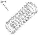
图26是根据所公开的主题的插入物的另一实施方式的截面的截面图;Figure 26 is a cross-sectional view of a section of another embodiment of an insert according to the disclosed subject matter;
图27是根据所公开的主题的图26的插入物的透视图;27 is a perspective view of the insert of FIG. 26 according to the disclosed subject matter;
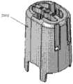
图28至图31是根据所公开的主题的图26的插入物的部件的透视图;28-31 are perspective views of components of the insert of FIG. 26 according to the disclosed subject matter;
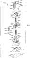
图32示出了根据所公开的主题的图26的插入物的分解图;Figure 32 shows an exploded view of the insert of Figure 26 in accordance with the disclosed subject matter;
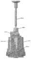
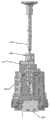
图33是根据所公开的主题的图26的插入物的侧视图;33 is a side view of the insert of FIG. 26 according to the disclosed subject matter;
图34至图36是根据所公开的主题的图26的插入物的透明侧视图;34-36 are transparent side views of the insert of FIG. 26 in accordance with the disclosed subject matter;
图37是根据所公开的主题的另一实施方式的插入物;Figure 37 is an insert according to another embodiment of the disclosed subject matter;
图38是根据所公开的主题的图37的插入物的截面的透视图;38 is a perspective view of a cross-section of the insert of FIG. 37 according to the disclosed subject matter;
图39是根据所公开的主题的图37的插入物的横截面图;39 is a cross-sectional view of the insert of FIG. 37 according to the disclosed subject matter;
图40是根据所公开的主题的图37的插入物的侧视图;Figure 40 is a side view of the insert of Figure 37 in accordance with the disclosed subject matter;
图41至图44是根据所公开的主题的图37的插入物的部件的透视图;41-44 are perspective views of components of the insert of FIG. 37 according to the disclosed subject matter;
图45是根据所公开的主题的图37的插入物的分解图;Figure 45 is an exploded view of the insert of Figure 37 in accordance with the disclosed subject matter;
图46是根据所公开的主题的图37的插入物的透明侧视图;46 is a transparent side view of the insert of FIG. 37 in accordance with the disclosed subject matter;
图47至图51是根据所公开的主题的另一插入物的透视图;47-51 are perspective views of another insert according to the disclosed subject matter;
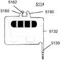
图52是所公开的主题的另一实施方式的分解透视图;Figure 52 is an exploded perspective view of another embodiment of the disclosed subject matter;
图53是根据所公开的主题的插入物的截面图;Figure 53 is a cross-sectional view of an insert according to the disclosed subject matter;
图54至图55是从图53的插入物的下方看的透视图;Figures 54-55 are perspective views from below the insert of Figure 53;
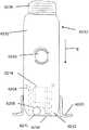
图56是根据所公开的主题的另一插入物的透视图;Figure 56 is a perspective view of another insert according to the disclosed subject matter;
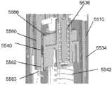
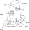
图57至图60是图56的插入物的各种部件的透视图;57-60 are perspective views of various components of the insert of FIG. 56;
图61至图62是图56的插入物的各种部件的透视图;61-62 are perspective views of various components of the insert of FIG. 56;
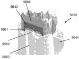
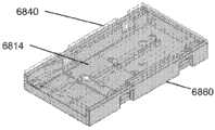
图63至图65示出了图56的插入物的部件的不同子组件;Figures 63 to 65 show different subassemblies of the components of the insert of Figure 56;
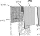
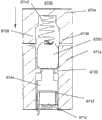
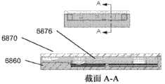
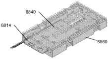
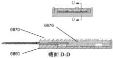
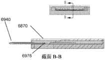
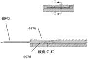
图66至图67是图56的插入物的部件的子组件的横截面图;66-67 are cross-sectional views of subassemblies of components of the insert of FIG. 56;
图68至图70示出了用来启动图56的插入物的步骤;Figures 68 to 70 illustrate the steps used to activate the insert of Figure 56;
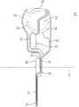
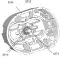
图71是根据所公开的主题的插入物组件的透视图;Figure 71 is a perspective view of an insert assembly according to the disclosed subject matter;
图72是根据所公开的主题的图71的插入物组件的部件的透视图;72 is a perspective view of components of the insert assembly of FIG. 71 in accordance with the disclosed subject matter;
图73是根据所公开的主题的分析物测量系统的部件的透视图;73 is a perspective view of components of an analyte measurement system according to the disclosed subject matter;
图74是根据所公开的主题的图71的插入物组件的分开部分的透视图;74 is a perspective view of separate portions of the insert assembly of FIG. 71 according to the disclosed subject matter;
图75是根据所公开的主题的图71的插入物组件的横截面图;75 is a cross-sectional view of the insert assembly of FIG. 71 in accordance with the disclosed subject matter;
图76是根据所公开的主题的插入物组件的一部分的侧视图;Figure 76 is a side view of a portion of an insert assembly according to the disclosed subject matter;
图77是根据所公开的主题的分析物传感器的视图;Figure 77 is a view of an analyte sensor according to the disclosed subject matter;
图78至图79是根据所公开的主题的插入物组件的一部分的透视图;78-79 are perspective views of a portion of an insert assembly according to the disclosed subject matter;
图80至图90是根据所公开的主题的分析物传感器的视图;80-90 are views of an analyte sensor according to the disclosed subject matter;
图91至图92是根据所公开的主题的插入物组件的横截面图;91-92 are cross-sectional views of an insert assembly according to the disclosed subject matter;
图93至图94是根据所公开的主题的另一插入物组件的横截面图;93-94 are cross-sectional views of another insert assembly according to the disclosed subject matter;
图95至图96是根据所公开的主题的另一插入物组件的横截面图;95-96 are cross-sectional views of another insert assembly according to the disclosed subject matter;
图97至图98是根据所公开的主题的插入物组件的一部分的视图;97-98 are views of a portion of an insert assembly according to the disclosed subject matter;
图99是根据所公开的主题的插入物组件的一部分的横截面图;Figure 99 is a cross-sectional view of a portion of an insert assembly according to the disclosed subject matter;
图100至图101是根据所公开的主题的插入物组件的一部分的透视图;100-101 are perspective views of a portion of an insert assembly according to the disclosed subject matter;
图102至图105是根据所公开的主题的各种插入物组件的侧视图;102-105 are side views of various insert assemblies according to the disclosed subject matter;
图106至图112是根据所公开的主题的尖端和尖端载体的视图;106-112 are views of a tip and tip carrier according to the disclosed subject matter;
图113是根据所公开的主题的插入物组件的一部分的透视图;Figure 113 is a perspective view of a portion of an insert assembly according to the disclosed subject matter;
图114至图117是示出了根据所公开的主题的插入物组件的操作的透视图;114-117 are perspective views illustrating the operation of an insert assembly according to the disclosed subject matter;
图118是根据所公开的主题的插入物组件的侧视图;Figure 118 is a side view of an insert assembly according to the disclosed subject matter;
图119至图121是根据所公开的主题的插入物组件的横截面图;119-121 are cross-sectional views of an insert assembly according to the disclosed subject matter;
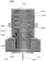
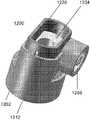
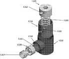
图122是根据所公开的主题的尖端/传感器盒的一个实施方式的分开部分的透视图;Figure 122 is a perspective view of separated parts of one embodiment of a tip/sensor cartridge according to the disclosed subject matter;
图123是根据所公开的主题的第一配置阶段中图122的盒子的透视图;Figure 123 is a perspective view of the box of Figure 122 in a first configuration stage according to the disclosed subject matter;
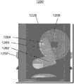
图124是根据所公开的主题的中性(neutral)状态中图122的盒子的横截面图;Figure 124 is a cross-sectional view of the box of Figure 122 in a neutral state according to the disclosed subject matter;
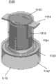
图125是根据所公开的主题的中性状态中图122的盒子的透视图;Figure 125 is a perspective view of the box of Figure 122 in a neutral state according to the disclosed subject matter;
图126是根据所公开的主题的第一配置阶段中图122的盒子的横截面图;Figure 126 is a cross-sectional view of the box of Figure 122 in a first configuration stage according to the disclosed subject matter;
图127是根据所公开的主题的第二配置阶段中图122的盒子的透视图;Figure 127 is a perspective view of the box of Figure 122 in a second configuration stage according to the disclosed subject matter;
图128是根据所公开的主题的第二配置阶段中图122的盒子的横截面图;128 is a cross-sectional view of the box of FIG. 122 in a second configuration stage according to the disclosed subject matter;
图129是根据所公开的主题的第三配置阶段中图122的盒子的透视图;129 is a perspective view of the box of FIG. 122 in a third configuration stage according to the disclosed subject matter;
图130是根据所公开的主题的第三配置阶段中图122的盒子的横截面图;Figure 130 is a cross-sectional view of the box of Figure 122 in a third configuration stage according to the disclosed subject matter;
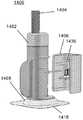
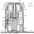
图131是根据所公开的主题的插入物的部件的另一实施方式的分开部分的透视图;Figure 131 is a perspective view of separate parts of another embodiment of components of an insert according to the disclosed subject matter;
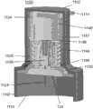
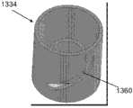
图132是根据所公开的主题的中性状态中图131的盒子的透视图;Figure 132 is a perspective view of the box of Figure 131 in a neutral state according to the disclosed subject matter;
图133是根据所公开的主题的中性状态中图131的盒子的横截面图;Figure 133 is a cross-sectional view of the box of Figure 131 in a neutral state according to the disclosed subject matter;
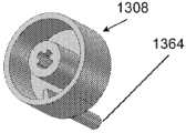
图134是根据所公开的主题的第二配置阶段中图131的盒子的透视图;Figure 134 is a perspective view of the box of Figure 131 in a second configuration stage according to the disclosed subject matter;
图135是根据所公开的主题的第二配置阶段中图131的盒子的横截面图;Figure 135 is a cross-sectional view of the box of Figure 131 in a second configuration stage according to the disclosed subject matter;
图136是根据所公开的主题的第三配置阶段中图131的盒子的透视图;Figure 136 is a perspective view of the box of Figure 131 in a third configuration stage according to the disclosed subject matter;
图137是根据所公开的主题的第三配置阶段中图131的盒子的横截面图。137 is a cross-sectional view of the cassette of FIG. 131 in a third configuration stage according to the disclosed subject matter.
具体实施方式Detailed ways
这里提供了本公开的详细描述。应理解,结合以下描述,该主题并非限于所描述的特定实施方式,因为该主题的特定实施方式当然可以改变。还将理解,这里使用的术语仅是为了描述特定实施方式的目的,并非意在是限制性的,因为所公开的主题的范围将仅由所附权利要求限制。A detailed description of the disclosure is provided here. It is to be understood, in conjunction with the following description, that the subject matter is not limited to particular embodiments described, as such may, of course, vary. It is also to be understood that the terminology used herein is for the purpose of describing particular embodiments only, and is not intended to be limiting, since the scope of the disclosed subject matter will be limited only by the appended claims.
在提供一定范围的值的地方,可理解,该范围的上限和下限之间的插入值、以及该所述范围中的任何其他所述的或插入的值均包含在所公开的主题内。每个所述范围还意在特别地公开所述范围的每个“子范围”。也就是说,还将每个比由对一个范围(其上限和下限在从外部下限到外部上限的范围内(除非上下文清楚地表明不是这样))给定的外部上限和外部下限的值指定的外部范围小的范围理解成包含在所公开的主题内,服从任何特定排除的范围或所述范围内的限制。在通过指定上限和下限中的一者或两者来规定范围的情况下,排除那些所述极限中的任一者或两者的或包括极限中的一者或两者的范围也包含在所公开的主题内,不管在描述范围时是否使用诸如“从”、“到”、“通过”或“包括”的词语。Where a range of values is provided, it is understood that intervening values between the upper and lower limits of the range, as well as any other stated or intervening values in the stated range, are encompassed within the disclosed subject matter. Each stated range is also intended to specifically disclose each "sub-range" of that range. That is, each ratio is also specified by the values of the upper and lower outer bounds given for a range whose upper and lower bounds lie in the range from the outer lower bound to the outer upper bound (unless the context clearly indicates otherwise) Smaller ranges of outer ranges are understood to be encompassed within the disclosed subject matter, subject to any specifically excluded range or limitation within said range. Where a range is stated by specifying one or both of upper and lower limits, ranges excluding either or both of those stated limits or including either or both of the limits are also included within the stated limits. Within the disclosed subject matter, regardless of whether words such as "from", "to", "via" or "including" are used in describing the range.
除非另有规定,本文使用的所有科技词汇具有本发明所属领域的普通技术人员通常所了解的相同含义。尽管任何类似于或等同于本文所述的方法及材料也可用于对本公开的主题进行实践或测试,但现在只对优选方法及材料进行阐述。Unless defined otherwise, all technical and scientific terms used herein have the same meaning as commonly understood by one of ordinary skill in the art to which this invention belongs. Although any methods and materials similar or equivalent to those described herein can also be used in the practice or testing of the presently disclosed subject matter, the preferred methods and materials are now described.
除非另外说明,否则为了所有目的通过引证结合于此的在本公开中提到的所有公开物包括但不限于公开和描述这些公开物所提到的方法和/或材料。Unless otherwise indicated, all publications mentioned in this disclosure are hereby incorporated by reference for all purposes including, but not limited to, disclosing and describing the methods and/or materials in question.
仅为了其在本申请的申请日之前的公开而提供这里讨论的公开物。不应将这里的任何公开物理解成不允许在这种公开物之前由于在先发明而授权本公开的主题。此外,所提供的公开日可能与实际的公开日不同,此实际的公开日可能需要单独确认。The disclosure discussed herein is provided solely for its disclosure prior to the filing date of the present application. Nothing herein should be construed as an admission that the subject matter of the present disclosure is entitled to prior invention by virtue of prior invention of such disclosure. In addition, the dates of publication provided may differ from the actual publication dates, which may need to be independently confirmed.
如这里使用的和在所附权利要求中使用的,单数形式“一”、“该”、“所述”包括复数对象,除非上下文明确表示不是这样。As used herein and in the appended claims, the singular forms "a", "the", and "said" include plural referents unless the context clearly dictates otherwise.
不应将摘要或发明内容中包含的任何部分理解成限制公开范围。为了著录和方便的目的而提供摘要和发明内容,由于其格式和目的的原因,不应将其认为是全面的。Nothing contained in the Abstract or Summary should be construed as limiting the scope of the disclosure. The Abstract and Summary are provided for descriptive and convenience purposes and should not be considered comprehensive due to their format and purpose.
如本领域的技术人员将在阅读此公开内容的基础上理解的,这里描述并示出的各个实施方式中的每一个均具有不连续的部件和特征,在不背离本公开的主题的范围或实质的前提下,可容易将其与任何其他几个实施方式的特征分离或组合。可以所述事件的顺序、或以逻辑上可能的任何其他顺序执行任何所述方法。As will be understood by those skilled in the art upon reading this disclosure, each of the various embodiments described and illustrated herein has discrete components and features without departing from the scope or scope of the disclosed subject matter. It can be easily separated or combined with any other features of several embodiments under the essential premise. Any described method may be performed in the order of events described, or in any other order that is logically possible.
对单个物品的参考包括存在多个相同物品的可能性。当用替代性的“或”提到两个或更多个物品(例如,部件或方法)时,这表示,任一个可分开地存在,或者其任何组合可一起存在,除了必须排除另外一个或更多个存在的情况。References to a single item include the possibility that there may be a plurality of the same item. When an alternative "or" is used to refer to two or more items (eg, parts or methods), this means that either may exist separately, or any combination thereof, together, unless the other or More situations exist.
通常,本公开的实施方式涉及用于将医疗装置至少部分地插入患者的皮肤中的设备。一些实施方式涉及检测体液中的至少一种分析物(例如葡萄糖)的体内方法和装置。因此,实施方式包括体内分析物传感器,其被构造为使得将传感器的至少一部分定位在用户体内(例如ISF内),以获得关于身体的至少一种分析物的信息,例如经皮定位在用户的身体中。在某些实施方式中,将体内分析物传感器与保持在用户身体上的电子装置单元接合,以处理从传感器获得的信息。In general, embodiments of the present disclosure relate to apparatus for at least partially inserting a medical device into the skin of a patient. Some embodiments relate to in vivo methods and devices for detecting at least one analyte (eg, glucose) in a bodily fluid. Accordingly, embodiments include an in vivo analyte sensor configured such that at least a portion of the sensor is positioned within a user's body (e.g., within an ISF) to obtain information about at least one analyte of the body, e.g., percutaneously positioned on the user's in the body. In certain embodiments, the in vivo analyte sensor is coupled to an electronics unit held on the user's body to process information obtained from the sensor.
在某些实施方式中,将分析物信息从第一装置(例如体上电子装置单元)传递至第二装置(其可能包括用户界面特征,包括显示器等)。当可获得分析物信息时,可将信息从第一装置自动地和/或连续地传递至第二装置,或者可以不自动地和/或连续地传递,而是储存或记录在第一装置的存储器中。因此,在系统的许多实施方式中,仅当用户询问时,以用户可用的或看得见的形式获得由传感器/体上电子装置(例如体上电子装置)得到的分析物信息,从而使得用户选择数据通信的定时。在一些实施方式中,在没有数据通信的定时时,用户选择显示信息。In certain embodiments, analyte information is communicated from a first device (eg, an on-body electronics unit) to a second device (which may include user interface features, including a display, etc.). When analyte information is available, the information may be automatically and/or continuously transferred from the first device to the second device, or may not be automatically and/or continuously transferred, but stored or recorded in the first device's in memory. Thus, in many embodiments of the system, analyte information obtained from sensors/on-body electronics (e.g., on-body electronics) is obtained in a form available or visible to the user only when asked by the user, thereby allowing the user to Select the timing of data communication. In some implementations, the user elects to display the information when there is no timing for data communication.
这样,在一些实施方式中,仅当用户需要时,向用户提供分析物信息,该信息对用户来说是明显的(设置在用户界面装置上),即使体内分析物传感器自动和/或连续监测体内分析物水平,即传感器在其使用寿命期间按照预定时间间隔自动监测分析物(如血糖)。例如,在指定的检测时间段内(如约14天)将分析物传感器进行体内定位并耦连至体上电子装置。在某些实施例中,将传感器产生的分析物信息自动从传感器电子组件传输至远程监测装置或显示装置,以便根据体上电子装置设定的时间表(例如约每1分钟、约每5分钟或约每10分钟等)在14天内输出至用户。在某些实施例中,传感器产生的分析物信息在用户规定的时间(例如当用户决定检查分析物信息的任何时间)只从传感器电子组件传输至远程监测装置或显示装置。此时,激活通信系统,并然后将传感器产生的信息从体上电子装置发送至远程装置或显示装置。As such, in some embodiments, analyte information is provided to the user, which is apparent to the user (provided on the user interface device), only when requested by the user, even if the in vivo analyte sensor automatically and/or continuously monitors Analyte levels in the body, where the sensor automatically monitors the analyte (such as blood glucose) at predetermined intervals during its lifetime. For example, an analyte sensor is positioned in vivo and coupled to on-body electronics for a specified detection period (eg, about 14 days). In certain embodiments, the sensor-generated analyte information is automatically transmitted from the sensor electronics to a remote monitoring device or display device so that it can be performed according to a schedule (e.g., about every 1 minute, about every 5 minutes) set by the on-body electronics. or approximately every 10 minutes, etc.) to the user within 14 days. In certain embodiments, sensor-generated analyte information is only transmitted from the sensor electronics to the remote monitoring device or display device at user-specified times (eg, any time the user decides to review the analyte information). At this point, the communication system is activated and then the information generated by the sensors is sent from the on-body electronics to a remote or display device.
在其他实施例中,当分析物信息可用时,可将信息自动和/或连续地从第一装置传输至第二装置,并且第二装置存储或记录接收的信息而不向用户呈现或输出该信息。在此类实施例中,当信息可用时(例如,当传感器根据时间表检测分析物水平时),通过第二装置从第一装置接收该信息。然而,接收的信息最初存储在第二装置中,并且在检测到对第二装置上的信息的请求时,只输出给第二装置的用户界面或输出装置(如显示器)。In other embodiments, when analyte information is available, the information may be automatically and/or continuously transmitted from the first device to the second device, and the second device stores or records the received information without presenting or outputting the information to the user. information. In such embodiments, the information is received by the second device from the first device when the information is available (eg, when the sensor detects analyte levels according to a schedule). However, the received information is initially stored in the second device and is only output to a user interface or output device (such as a display) of the second device when a request for information on the second device is detected.
相应地,在某些实施例中,一旦本文所述的插入物用来将传感器电子组件件放置到身体上,使得体内传感器的至少一部分与体液(如ISF)接触。一旦传感器与电子部件电耦连时,可以通过给显示装置通电(或连续供电)并执行存储在并取自显示装置的存储器的软件算法将传感器产生的分析物信息从体上电子装置传输至所需显示装置,生成一个或更多个请求命令,控制信号或数据包发送至体上电子装置。显示装置的微处理器或专用集成电路(ASIC)的控制下执行的软件算法包括检测体上电子装置相对于显示装置的位置的程序,以促使传输生成的请求命令、控制信号和/或数据包。Accordingly, in certain embodiments, once an insert as described herein is used to place a sensor electronics assembly on the body, at least a portion of the sensor in the body is brought into contact with bodily fluid (eg, ISF). Once the sensor is electrically coupled to the electronics, the sensor-generated analyte information can be transmitted from the on-body electronics to the on-body electronics by energizing (or continuing to power) the display device and executing software algorithms stored in and retrieved from the display device's memory. The display device is required to generate one or more request commands, control signals or data packets to the on-body electronics. Software algorithms executed under the control of the display device's microprocessor or application specific integrated circuit (ASIC) include routines to detect the position of the on-body electronics relative to the display device to cause transmission of generated request commands, control signals and/or data packets .
显示装置可还包括存储在存储器中由一个或更多个微处理器和/或ASIC执行的程序,以响应于用户激活显示装置上的输入机构(如按下显示装置上的按钮、触发数据通信功能相关的软按钮等),生成一个或更多个请求命令、控制信号或数据包,并传输以发送至体上电子装置。将输入机构可替换地或额外地设置在构造成用于用户激活的体上电子装置上或之中。在某些实施例中,语音命令或音频信号可用于促使或指示微处理器或ASIC执行存储在存储器中的软件程序,以生成一个或更多个请求命令、控制信号或数据包并传输至体内装置。在语音激活或响应于语音命令或音频信号的实施例中,体上电子装置和/或显示装置包括麦克风、扬声器及存储在体上电子装置和/或显示装置的各个存储器中用来处理语音命令或音频信号的处理程序。在某些实施例中,将体内装置和显示装置相对于彼此定位于预定距离(例如接近距离)内启动了一个或更多个存储在显示装置的存储器中的软件程序,以生成并传输请求命令、控制信号或数据包。The display device may further include a program stored in memory to be executed by one or more microprocessors and/or ASICs to respond to user activation of an input mechanism on the display device (such as pressing a button on the display device, triggering a data communication Function-related soft buttons, etc.), generate one or more request commands, control signals or data packets, and transmit to send to the body electronics. The input mechanism may alternatively or additionally be provided on or in the on-body electronic device configured for user activation. In some embodiments, voice commands or audio signals may be used to cause or instruct a microprocessor or ASIC to execute a software program stored in memory to generate and transmit one or more request commands, control signals or data packets to the body device. In embodiments that are voice-activated or responsive to voice commands or audio signals, the on-body electronics and/or display include a microphone, a speaker, and various memories stored in the on-body electronics and/or display for processing the voice commands. or audio signal handlers. In some embodiments, positioning the in-body device and the display device within a predetermined distance (e.g., proximity distance) relative to each other activates one or more software programs stored in the memory of the display device to generate and transmit the request command , control signals or data packets.
可发送不同类型和/或形式和/或数量的信息以满足每个所需阅读,阅读需求包括但不限于以下的一个或更多个:当前分析物水平信息(即时间上与启动阅读的时间相对应的实时或最近获得的分析物水平信息)、预定时间段内的分析物的变化率、分析物变化率的速率(变化率加速度)、与在指定阅读之前获得并存储在组件的存储器中的分析物信息相对应的历史分析物信息。可以将实时、历史、变化率、变化率速率(如加速度或减速度)信息中的一些或全部发送至显示装置,供指定阅读。在某些实施例中,发送至显示装置的信息的类型和/或形式和/或数量可以是被预编程和/或不可更改的(如在制造过程中预设),或可以不是被预编程和/或不可更改的,以便在本领域可选择和/或可更改一次或多次(如通过激活系统的开关等)。相应地,在某些实施例中,针对每个所需阅读,显示装置将输出当前(实时)传感器产生的分析物数值(如以数字格式)、当前分析物变化率(如以分析物速率指示物的形式,比如指向指示当前速率的方向的箭头)、以及基于由体上电子装置的存储器获取并存储于其中的传感器读数的分析物走势历史数据(如,以图形轨迹形式)。另外,将与每个所需阅读相关的皮肤上或传感器上的温度读数或测量值从体上电子装置传输至显示装置。但是,温度读数或测量值可能不输出或显示在显示装置上,而可以结合由显示装置执行的软件程序使用以便纠正或补偿在显示装置上向用户输出的分析物测量值。Different types and/or forms and/or amounts of information can be sent to meet each desired read, which includes, but is not limited to, one or more of the following: current analyte level information (i.e., temporally relative to corresponding real-time or most recently obtained analyte level information), the rate of change of the analyte over a predetermined period of time, the rate of the rate of change of the analyte (rate-of-change acceleration), and The analyte information corresponding to the historical analyte information. Some or all of the real-time, historical, rate-of-change, rate-of-change (such as acceleration or deceleration) information can be sent to the display device for designated reading. In some embodiments, the type and/or form and/or amount of information sent to the display device may be pre-programmed and/or unalterable (eg, preset during manufacture), or may not be pre-programmed and/or non-alterable, so that it can be selected and/or changed one or more times in the field (such as by activating a switch of the system, etc.). Accordingly, in certain embodiments, for each desired reading, the display device will output the current (real-time) sensor-generated analyte value (e.g., in digital format), the current analyte rate of change (e.g., as indicated by the analyte rate in the form of an analyte, such as an arrow pointing in a direction indicating the current rate), and historical data (eg, in the form of a graphical trace) of the analyte trend based on sensor readings captured by and stored in the memory of the on-body electronics device. In addition, temperature readings or measurements on the skin or on sensors associated with each desired reading are transmitted from the on-body electronics to the display device. However, the temperature reading or measurement may not be output or displayed on the display device, but may be used in conjunction with a software program executed by the display device to correct or compensate for the analyte measurement output to the user on the display device.
如上所述,实施例包括体内分析物传感器和体上电子装置,体内分析物传感器和体上电子装置一起提供躯体可佩戴式传感器电子组件。在某些实施例中,体内分析物传感器与体上电子装置完全接合为一体(制造期间固定连接),然而在其他实施例中,体内分析物传感器与体上电子装置在制造后是独立但可连接的(例如,在传感器插入身体之前、插入过程中或插入之后)。体上电子装置可包括容纳(除了用于体内定位的传感器部分之外)在包括粘附垫或可附接至粘附垫的防水外壳中的体内葡萄糖传感器、电子装置、电池及天线。在某些实施例中,该外壳能承受浸在水下一米处高达至少30分钟。在某些实施例中,该外壳能承受连续水下接触例如超过约30分钟,并根据其预期使用继续正常运转,而例如在外壳适用于水浸没的情况下不会对外壳电子装置造成水损坏。As noted above, embodiments include an in vivo analyte sensor and on-body electronics that together provide a body-wearable sensor electronics assembly. In some embodiments, the in vivo analyte sensor and on-body electronics are fully integrated (fixed connection during manufacture), while in other embodiments, the in-vivo analyte sensor and on-body electronics are separate but removable after manufacture. Connected (eg, before, during, or after insertion of the sensor into the body). The on-body electronics may include an on-body glucose sensor, electronics, battery, and antenna housed (in addition to the sensor portion for in-vivo positioning) in a waterproof housing that includes or is attachable to an adhesive pad. In certain embodiments, the housing is capable of withstanding submersion in water to one meter for up to at least 30 minutes. In certain embodiments, the housing is capable of withstanding continuous underwater exposure, e.g., for more than about 30 minutes, and continues to function normally in accordance with its intended use, without causing water damage to the housing electronics, e.g., where the housing is suitable for submersion in water .
实施例包括传感器插入装置,其还可被称为传感器传送单元等。插入装置可将体上电子装置组件完全保持在内隔室中,即,插入装置在制造过程期间可预装有体上电子装置组件(例如,可将体上电子装置封装在插入装置的无菌内隔室中)。在此类实施例中,插入装置可形成用于预先使用的传感器组件封装件(包括无菌封装件)或新的体上电子装置组件、和构造为将体上电子装置组件应用于患者身体的插入装置。Embodiments include sensor insertion devices, which may also be referred to as sensor delivery units, and the like. The insertion device may fully retain the on-body electronics assembly in the inner compartment, i.e., the insertion device may be pre-loaded with the on-body electronics assembly during the manufacturing process (e.g., the on-body electronics may be packaged in a sterile container of the insertion device. in the inner compartment). In such embodiments, the insertion device may form a package for a pre-used sensor assembly (including a sterile package) or a new on-body electronics assembly, and be configured to apply the on-body electronics assembly to the patient's body. Insert the device.
实施例包括便携式手持显示装置,便携式手持显示装置作为与体上电子装置组件间隔开的独立装置,从组件收集信息并为用户提供传感器产生的分析物读数。这种装置还可被称为计量器、读取器、监测器、接收器、人机接口装置、成对部件等。某些实施例可包括一体的体外分析物计量器。在某些实施例中,显示装置包括一个或更多个有线或无线通信端口,如USB、串行端口、并行端口等,构造为建立显示装置与另一单元(如体上电子装置、给电池再充电的供电单元、PC等)之间的通信。例如,显示装置的通信端口可以能够利用各自的充电电缆对显示装置电池充电和/或在显示装置与其兼容信息软件之间进行数据交换。Embodiments include a portable handheld display device as a stand-alone device spaced apart from on-body electronics components, collecting information from the components and providing a sensor-generated analyte readout to the user. Such devices may also be called gauges, readers, monitors, receivers, human interface devices, paired components, and the like. Certain embodiments may include an integral in vitro analyte meter. In some embodiments, the display device includes one or more wired or wireless communication ports, such as USB, serial port, parallel port, etc., configured to establish communication between the display device and another unit (such as on-body electronics, battery communication between the recharging power supply unit, PC, etc.). For example, the communication port of the display device may be capable of charging the display device battery and/or exchanging data between the display device and its compatible messaging software using a respective charging cable.
某些实施例中的兼容信息软件包括但不限于例如在显示装置、个人计算机、服务器终端上存在或在其上运行的独立或网络连接使能的(enabled)数据管理软件程序,例如以便进行数据分析、制作图表、数据存储、数据存档和数据通信以及数据同步化。某些实施例中的信息软件还可包括这样的软件,该软件用于执行可现场升级功能对显示装置和/或体上电子部件的硬件进行升级以便对显示装置和/或体上电子部件上存在的软件进行升级,而例如包括其他部件和/或包括软件缺陷或误差的硬件版本是固定的等等。实施例可包括触觉反馈部件(如振动马达等),其构造使得可以触觉反馈的形式传递相应的通知(例如,显示装置接收的成功所需读数)。Compatible information software in certain embodiments includes, but is not limited to, stand-alone or network connection enabled data management software programs that exist or run on, for example, display devices, personal computers, server terminals, e.g. Analysis, graphing, data storage, data archiving and data communication, and data synchronization. The information software in some embodiments may also include software for performing a field-upgradeable function to upgrade the hardware of the display device and/or on-body electronics for updating the display device and/or on-body electronics Existing software is upgraded, while for example hardware versions including other components and/or including software bugs or errors are fixed, etc. Embodiments may include tactile feedback components (eg, vibrating motors, etc.) configured such that corresponding notifications may be communicated in the form of tactile feedback (eg, display device received required readings for success).
实施例包括嵌入计算机可读介质上的程序,即基于计算机的应用软件(本文中还可被称为信息软件或程序等),其具有从系统获得的分析物信息和/或用户自报数据。通过显示装置或体上电子部件将应用软件安装到主机,例如手机、PC、诸如网络电话的互联网使能的人机接口装置、个人数字助理等。信息程序可以转换在显示装置上或体内单元上获得的并存储的数据,以供用户使用。Embodiments include a program, ie, computer-based application software (also referred to herein as information software or program, etc.) embedded on a computer-readable medium with analyte information and/or user-reported data obtained from the system. Application software is installed to a host computer, such as a cell phone, PC, Internet-enabled human interface device such as a VoIP, personal digital assistant, etc., through a display device or on-body electronics. The information program can convert the data obtained and stored on the display device or on the in-body unit for use by the user.
仅为了方便起见,主要针对葡萄糖监测装置和系统、及葡萄糖监测方法描述了本公开的实施例,并且该描述并不用来限制本发明的范围。应理解,分析物监测系统可构造为在相同时间或不同时间监测各种分析物。Embodiments of the present disclosure are described primarily in terms of glucose monitoring devices and systems, and glucose monitoring methods, for convenience only, and the description is not intended to limit the scope of the invention. It should be understood that the analyte monitoring system can be configured to monitor various analytes at the same time or at different times.
详细描述如下,实施例包括在预定监测时间段监测一个或更多个生理参数的装置、系统、试剂盒和/或方法,参数诸如为但不限于分析物水平、温度水平、心率、用户活动水平。还提供了制造方法。预定监测时间段可以小于约1小时,或者可包括约1小时以上,例如约几小时以上、例如约几天以上、例如约3天以上、例如约5天以上、例如约7天以上、例如约10天以上、例如约14天以上、例如约几个星期、例如约1个月以上。在某些实施例中,预定监测时间段到期后,系统的一个或更多个部件可自动在体上电子装置组件和/或显示装置中停用或禁用。As described in detail below, embodiments include devices, systems, kits and/or methods for monitoring one or more physiological parameters such as, but not limited to, analyte levels, temperature levels, heart rate, user activity levels, over a predetermined monitoring period of time . Methods of manufacture are also provided. The predetermined monitoring period may be less than about 1 hour, or may include more than about 1 hour, such as more than about several hours, such as more than about several days, such as more than about 3 days, such as more than about 5 days, such as more than about 7 days, such as about 10 days or more, such as about 14 days or more, for example about several weeks, for example about 1 month or more. In certain embodiments, one or more components of the system may be automatically deactivated or disabled in the on-body electronics assembly and/or display device upon expiration of a predetermined monitoring period.
例如,预定监测时间段可始于将传感器定位于体内并与体液(诸如ISF)接触,和/或始于体上电子装置的启动(或通电为完全运作模式)。体上电子装置的初始化可通过由以下之一生成并传输的命令来实现:通过显示装置响应于开关的激活、和/或通过将显示装置放置到距体上电子装置在预定距离(如接近距离)内、或通过用户手动激活体上电子单元上的开关(例如按下按钮),或者这些激活可以由插入装置产生,例如正如2010年2月1日提交的第12/698,129号美国专利申请、及第61/238,646、61/246,825、61/247,516、61/249,535、61/317,243、61/345,562及61/361,374号美国临时申请所述,这些文献中的每一个的公开内容均通过引证结合于本文用于所有目的。For example, the predetermined monitoring period may begin with positioning the sensor in the body and in contact with a bodily fluid, such as ISF, and/or with activation (or power-up to a fully operational mode) of the on-body electronics. Initialization of the on-body electronics may be accomplished through commands generated and transmitted by one of the following: by the display device in response to activation of the switch, and/or by placing the display device at a predetermined distance (e.g., proximity distance) from the on-body electronics device. ), or by the user manually activating a switch on the on-body electronics unit (e.g., pressing a button), or these activations can be generated by an intervening device, such as in US Patent Application No. 12/698,129 filed February 1, 2010, and U.S. Provisional Application Nos. 61/238,646, 61/246,825, 61/247,516, 61/249,535, 61/317,243, 61/345,562, and 61/361,374, the disclosures of each of which are incorporated by reference at This article is for all purposes.
当响应于接收的来自显示装置的命令进行初始化时,体上电子装置从其存储器获取并执行软件程序以便充分对体上电子装置的部件进行通电,响应于从显示装置接收激活命令而有效地将体上电子装置置于完全运作模式。例如,在接收到来自显示装置的命令之前,通过内部电源(诸如电池)对体上电子装置中的一部分部件供电,而体上电子装置中的另一部分部件处于掉电或低功率(包括无功率)停用模式,或者所有部件都处于停用模式、掉电模式。当接收命令时,将体上电子装置部件的剩余部分或所有部分切换为主动全运行模式。When initializing in response to receiving a command from the display device, the on-body electronics retrieves and executes a software program from its memory in order to power on the components of the on-body electronics sufficiently to effectively power the On-body electronics are placed in full operational mode. For example, some components of the on-body electronics are powered by an internal power source, such as a battery, while other components of the on-body electronics are powered down or at low power (including no power) until a command is received from the display device. ) disabled mode, or all components are in disabled mode, power-down mode. When a command is received, the remainder or all of the on-body electronics components are switched to an active full operational mode.
体上电子装置的实施例可包括具有包括在ASIC、微处理器、存储器等中执行的控制逻辑的电子装置的一个或更多个印刷电路板、以及形成单一组件的经皮定位的分析物传感器。当在一个预定的接近一时间段(例如约2分钟、例如小于约1分钟、例如小于约30秒、例如小于约10秒、例如小于约5秒、例如小于约2秒)内检测分析物监测系统的显示装置时、和/或直到在显示装置上输出确认(诸如声音和/或视频和/或触觉(振动))通知以指示成功从体上电子装置获取分析物相关信号时,体上电子装置可构造为提供与监测到的分析物水平相关的一个或更多个信号或数据包。在某些实施例中,对于失败的采集,还可以输出不同的通知。Embodiments of the on-body electronics may include one or more printed circuit boards with electronics including control logic implemented in an ASIC, microprocessor, memory, etc., and a transdermally positioned analyte sensor forming a single component. . When the analyte is detected within a predetermined approximately a period of time (e.g., about 2 minutes, such as less than about 1 minute, such as less than about 30 seconds, such as less than about 10 seconds, such as less than about 5 seconds, such as less than about 2 seconds) On the display device of the system, and/or until a confirmation (such as audio and/or visual and/or tactile (vibration)) notification is output on the display device to indicate successful acquisition of the analyte-related signal from the on-body electronics device, the on-body electronics The device may be configured to provide one or more signals or data packets related to the monitored analyte level. In some embodiments, different notifications may also be output for failed acquisitions.
在某些实施例中,监测到的分析物水平可以与血液或其他液体(如ISF)中的葡萄糖水平相关联和/或转换为葡萄糖水平。可利用体上电子装置来完成这种转换,但在许多实施例中,这种转换通过显示装置电子装置来完成。在某些实施例中,葡萄糖水平来源于ISF中监测的分析物水平。In certain embodiments, the monitored analyte levels can be correlated to and/or converted to glucose levels in blood or other fluids (eg, ISF). This conversion can be accomplished using on-body electronics, but in many embodiments, the conversion is accomplished through display device electronics. In certain embodiments, glucose levels are derived from analyte levels monitored in the ISF.
分析物传感器可以是可插入于静脉、动脉或身体的包含分析物的其他部分。在某些实施例中,分析物传感器可定位成与ISF接触以检测分析物水平,其中检测到的分析物水平可用于推断用户血液或间质组织中的葡萄糖水平。The analyte sensor may be insertable into a vein, artery, or other part of the body that contains the analyte. In certain embodiments, an analyte sensor can be positioned in contact with the ISF to detect analyte levels, wherein the detected analyte levels can be used to infer glucose levels in the user's blood or interstitial tissue.
实施例包括经皮传感器以及可整体植入式传感器和可整体植入式组件,其中将包括分析物传感器的单一组件和电子装置设置在密封外壳(例如,密封的生物相容性外壳)中,以便植入用户体内用于监测一个或更多个生理参数。Embodiments include transcutaneous sensors and integrally implantable sensors and integrally implantable assemblies, wherein a single assembly comprising an analyte sensor and electronics are disposed in a sealed housing (e.g., a sealed biocompatible housing), so as to be implanted in a user for monitoring one or more physiological parameters.
实施方式包括设置于小的、重量轻的、电池供电的和用电控制的系统中的分析物监测器。可将这种系统构造为,用电化学传感器检测对象的物理参数(例如表示体内分析物水平的信号),并通过或不通过处理来收集这种信号。可用任何适当的测量技术从传感器获得信号,例如,可检测电流,可使用电位法等。这些技术可包括,但不限于电流分析法、电量分析法和伏安法。在一些实施方式中,传感系统可以是光学的、比色的,等等。在一些实施方式中,可将执行此初始处理的系统的部分构造为对另一单元提供原数据或至少初始处理的数据,以进一步收集和/或处理。例如,可通过有线连接(例如电连接),或用无线连接(例如IR或RF连接)来提供这种数据。Embodiments include analyte monitors disposed in small, lightweight, battery powered and electrically controlled systems. Such a system can be configured to detect a physical parameter of a subject (eg, a signal indicative of an analyte level in the body) with an electrochemical sensor, and to collect such signal with or without processing. The signal may be obtained from the sensor by any suitable measurement technique, for example, current may be detected, potentiometric methods may be used, etc. These techniques may include, but are not limited to, amperometry, coulometry, and voltammetry. In some embodiments, the sensing system can be optical, colorimetric, or the like. In some embodiments, the portion of the system performing this initial processing may be configured to provide raw data, or at least initially processed data, to another unit for further collection and/or processing. For example, such data may be provided via a wired connection, such as an electrical connection, or with a wireless connection, such as an IR or RF connection.
在某些系统中,分析物传感器与体上电子装置通信。体上单元可包括体上电子装置和传感器的至少一部分容纳于其中的壳体。In some systems, the analyte sensor communicates with on-body electronics. The on-body unit may include a housing in which at least a portion of the on-body electronics and sensors are housed.
某些实施方式是模块化的。可将体上单元单独提供为在物理上与监测器单元不同的组件,例如,其对用户显示或以其他方式表示分析物水平。可将体上单元构造为,在通信链路上对监测器单元提供由传感器检测的分析物水平和/或其他信息(例如温度、传感器使用寿命等)。在一些实施方式中,监测器单元可包括例如移动电话装置、体内葡萄糖测量计、个人数字助理,或其他消费者电子装置(例如MP3装置、照相机、收音机、个人电脑等),或其他使得能够通信的数据处理装置。Certain embodiments are modular. The on-body unit may be provided separately as a physically distinct component from the monitor unit, for example, which displays or otherwise indicates analyte levels to the user. The on-body unit may be configured to provide analyte levels detected by the sensors and/or other information (eg, temperature, sensor lifetime, etc.) to the monitor unit over a communication link. In some embodiments, the monitor unit may include, for example, a mobile telephone device, an in vivo glucose meter, a personal digital assistant, or other consumer electronic device (e.g., MP3 device, camera, radio, personal computer, etc.), or other device that enables communication data processing device.
显示器单元可执行各种功能,例如但不限于对所接收的分析物数据的数据存储和/或处理和/或分析和/或通信等,以产生与所监测的分析物水平相关的信息和/或处理其他信息。监测器单元可包含显示屏(其例如可用来显示所测量的分析物水平)、和/或以用声音对用户提供信息的音频部件(例如扬声器)、和/或对用户提供触觉反馈的振动装置。对于分析物监测系统的用户来说,能够看到趋势指示(包括任何正在进行的趋势的大小和方向,例如分析物的变化率或其他参数、以及对象高于和/或低于阈值(例如低葡萄糖和/高葡萄糖阈值)的时间量等)也是有用的;可用数字和/或用可视指示器显示这种数据,例如可改变可视属性的箭头,例如大小、形状、颜色、行为或方向。监测器单元可进一步适于从体内分析物测试条或者在体内分析物测试条附近接收信息,所述测试条可手动地或自动地进入监测器单元。在一些实施方式中,监测器单元可包含体内分析物测试条端口和相关的电子装置,以能够用体内测试条进行不连续的(例如血糖)测量(例如见6,175,752,其公开内容为了所有目的而通过引证结合于此)。The display unit may perform various functions such as, but not limited to, data storage and/or processing and/or analysis and/or communication of received analyte data, etc. to generate information related to the monitored analyte level and/or or process other information. The monitor unit may include a display screen (which, for example, may be used to display measured analyte levels), and/or an audio component (e.g., a speaker) to provide information to the user audibly, and/or a vibration device to provide tactile feedback to the user . For users of the analyte monitoring system, trend indications (including the magnitude and direction of any ongoing trends, such as rates of change of analytes or other parameters, and objects above and/or below thresholds (e.g., low Glucose and/high glucose threshold) amount of time, etc.) are also useful; this data can be displayed numerically and/or with a visual indicator, such as an arrow that can change a visual attribute, such as size, shape, color, behavior or direction . The monitor unit may further be adapted to receive information from or in the vicinity of an in vivo analyte test strip, which may be manually or automatically entered into the monitor unit. In some embodiments, the monitor unit may include an in vivo analyte test strip port and associated electronics to enable discrete (eg, blood glucose) measurements with an in vivo test strip (see, e.g., 6,175,752, the disclosure of which is for all purposes incorporated herein by reference).
在可将一个或更多个部件可构造为单次使用和可将一个或更多个部件可构造为可重复使用的情况下,这些系统的模块性可改变。在一些实施方式中,将传感器设计为能够与体上电子装置附接和从体上电子装置拆离(并且体上单元可以是可重复使用的),例如,使得部件中的一个或更多个可重复使用一次或多次,而在其他实施方式中,可将传感器和体上电子装置提供为一体的、不可拆离的封装,可将其设计为在使用后是抛弃的,即是不可重复使用的。The modularity of these systems can vary in that one or more components can be configured for single use and one or more components can be configured for reusable use. In some embodiments, the sensor is designed to be attachable to and detachable from the on-body electronics (and the on-body unit may be reusable), for example, such that one or more of the components Can be reused one or more times, while in other embodiments, the sensor and on-body electronics can be provided in an integral, non-detachable package that can be designed to be disposable after use, i.e., non-reusable in use.
体内监测系统的实施方式Embodiments of In Vivo Monitoring System
为了说明而不是限制的目的,这里描述的插入物可与图1所述的示例性分析物监测系统一起使用。应理解,这里描述的插入物可自己地或与系统接合地与任何医疗装置一起使用。图1示出了根据本公开实施方式的示例性的基于体内的分析物监测系统100。如所示出的,在某些实施方式中,分析物监测系统100包括与体内分析物传感器14电接合的体上电子装置1100(其近端部分在图1中示出,并附接至粘附层218以用于附接在用户身体上的皮肤表面上)。体上电子装置1100包括限定内部隔室的体上壳体122。For purposes of illustration and not limitation, the inserts described herein may be used with the exemplary analyte monitoring system described in FIG. 1 . It should be understood that the inserts described herein may be used with any medical device by itself or engaged with a system. FIG. 1 illustrates an exemplary in vivo-based analyte monitoring system 100 according to an embodiment of the disclosure. As shown, in some embodiments, the analyte monitoring system 100 includes on-body electronics 1100 (the proximal portion of which is shown in FIG. layer 218 for attachment to the skin surface on the user's body). The on-
图1中还示出了插入装置200(或这里描述的插入装置300、400、2400、2500、2700、3700),当操作时,入装置将分析物传感器14的一部分穿过皮肤表面经皮定位并与ISF流体接触,并将体上电子装置1100和粘附层218定位在皮肤表面上,如将在这里更详细地描述的。在某些实施方式中,在使用前将体上电子装置1100、分析物传感器14和粘附层218密封在插入装置200的壳体内,并且,在某些实施方式中,也将粘附层218密封在壳体内,或者粘附层能够提供密封以保持设备的无菌状态。例如,在美国专利申请号12/698,129和美国临时申请号61/238,646、61/246,825、61/247,516、61/249,535和61/345,562中讨论了与插入装置相关的其他细节,每篇申请的公开内容为了所有目的通过引证而结合于此。Also shown in FIG. 1 is insertion device 200 (or insertion devices 300, 400, 2400, 2500, 2700, 3700 as described herein), which, when in operation, percutaneously positions a portion of
返回参照上图1,分析物监测系统100包括:显示装置1200,该显示装置包括向用户输出信息的显示器1220;输入部件1210,诸如按钮、致动器,触敏开关、电容式开关、压敏开关、缓动盘(jog wheel)等,以向显示装置1200输入数据或命令或者控制显示装置1200的操作。值得注意的是,某些实施例可包括不含显示器的装置或没有用户界面部件的装置。这些装置可作为数据记录装置来用于存储数据和/或提供一根管道将数据从体上电子装置和/或不含显示器的装置传输至另一装置和/或位置。本文将阐述用作示例性目的的显示装置的实施例,其并不限制本发明的实施例。显而易见的是同样可以在某些实施例中使用不含显示器的装置。Referring back to FIG. 1 above, the analyte monitoring system 100 includes: a
在某些实施例中,体上电子装置1100构造为在监测时间段内将一些或所有接收自分析物传感器14的监测分析物相关数据存储在存储器中,并保持在存储器中直至使用期结束。在此类实施例中,在监测时间段结束时,例如,在通过从皮肤表面拆下在监测时间段内定位的体上电子装置1100而将分析物传感器14从用户身上拆下来之后,从体上电子装置1100获取存储的数据。在此类数据记录构造中,实时监测到的分析物水平在监测时间段内不传输至显示装置1200,或者以其它方式从体上电子装置1100传输而来,而是在监测时间段之后从体上电子装置1100获取。In certain embodiments, on-
在某些实施例中,显示装置1200的输入部件1210可包括麦克风,并且显示装置1200可包括构造为分析接收自麦克风的音频输入的软件,因此显示装置1200的功能和操作可由语音命令控制。在某些实施例中,显示装置1200的输出部件包括用于输出作为音频信号的信息的扬声器。为体上电子装置1100设置类似的语音响应部件,诸如扬声器、麦克风、及用于生成、处理和存储语音驱动信号的软件程序。In some embodiments, the input part 1210 of the
在某些实施例中,显示器1220和输入部件1210可集成到单一部件中,例如能够检测在显示器(如触摸屏用户界面)上的身体接触触摸的存在和位置的显示器。在此类实施例中,用户可通过使用一组预编程移动命令来控制显示装置1200的操作,包括但不限于单击或双击显示器、在显示器上拖动手指或仪器、朝彼此移动多个手指或仪器、将远离彼此移动多个手指或仪器等。在某些实施例中,显示器包括具有像素区的触摸屏,像素区具有用作LCD部件和触摸传感器的单一功能或双功能电容部件。In some embodiments, the display 1220 and the input component 1210 may be integrated into a single component, such as a display capable of detecting the presence and location of physical contact touches on the display (eg, a touch screen user interface). In such embodiments, the user can control the operation of the
显示装置1200还包括与诸如远程终端(个人计算机)1700等外部装置进行有线数据通信的数据通信端口1230。数据通信端口1230的实例包括构造为连接至可兼容数据电缆的USB端口、迷你USB端口、RS-232端口、以太网端口、火线端口或其类似数据通信端口。显示装置1200还可包括整体式体外葡萄糖仪,葡萄糖仪包括接收用于体外葡萄糖测量的体外葡萄糖试纸的体外试纸端口1240。The
仍然参照图1,某些实施例中的显示器1220被构造为显示多种信息,即,部分或全部信息可在同一时间或不同时间显示在显示器1220上。在某些实施例中,显示的信息是用户可选择的,以便用户能够自定义显示在指定显示屏上的信息。显示器1220可包括但不限于例如在监测时间段内提供葡萄糖值图形输出的图形显示器1380(其可显示诸如饮食、移动、睡眠、心率、血压等重要指标)、例如提供监测的葡萄糖值(该葡萄糖值是响应于信息请求获取或接收的)的数字显示器1320、以及例如通过移动显示器1220上的位置来指示分析物变化率和/或分析物变化率速率的走势或方向箭头显示器1310。Still referring to FIG. 1 , the display 1220 in some embodiments is configured to display a variety of information, ie, some or all of the information may be displayed on the display 1220 at the same time or at different times. In some embodiments, the displayed information is user-selectable so that the user can customize the information displayed on a given display screen. Display 1220 may include, but is not limited to, a graphical display 1380 (which may display important indicators such as diet, movement, sleep, heart rate, blood pressure, etc.) that provides a graphical output of glucose values over a monitoring period, such as providing monitored glucose values (the glucose Values are acquired or received in response to an information request), and a trend or directional arrow display 1310 indicating analyte rate of change and/or rate of analyte rate of change, such as by moving a position on display 1220 .
图1还示出,显示器1220还可包括例如为用户提供日期信息的日期显示器1350、为用户提供当日时间信息的当日时间信息显示器1390、以图形方式显示显示装置1200的电池状况(充电式或抛弃式)的电池电量指示显示器1330、例如在需要定期、常规或预定数量的用户校准事件的监测系统中通知用户有必要进行分析物传感器校准的传感器校准状态图标显示器1340、用于显示音频/振动输出或报警状态的音频/振动设置图标显示器1360、以及提供与诸如体上电子装置、数据处理模块1600和/或远程终端1700的其他装置进行无线通信连接指示的无线连接状态图标显示器1370。如图1另外示出的,显示器1220可进一步包括用于访问菜单、改变显示图形输出构造或用于控制显示装置1200操作的模拟触摸屏按钮1250、1260。1 also shows that the display 1220 can also include, for example, a date display 1350 for providing date information to the user, a time of day information display 1390 for providing the time of day information for the user, and a graphical display of the battery status of the display device 1200 (rechargeable or discarded). battery level indicator display 1330, such as in monitoring systems that require periodic, routine, or predetermined number of user calibration events, to notify the user of the need for analyte sensor calibration sensor calibration status icon display 1340, for displaying audio/vibration output audio/vibration
返回参照图1,在某些实施例中,显示装置1200的显示器1220(其附加于视觉显示器、或者替代视觉显示器)可构造为输出诸如报警和/或警报通知、葡萄糖值等的警告通知,警告通知可以是听得见的、可感触的或即听得见又可感触的。在一方面,显示装置1200可包括其他输出部件(如扬声器、振动输出部件等),以便除显示器1220上提供的可视输出指示外还为用户提供可听见的和/或振动的输出指示。在例如美国专利申请号12/871,901、美国临时申请号61/238,672,61/247,541,61/297,625中可获取进一步详情及其他显示器实施例,这些文献中的每一个的公开内容通过引用结合于本文用于所有目的。Referring back to FIG. 1 , in some embodiments, display 1220 of display device 1200 (in addition to, or in place of, a visual display) may be configured to output warning notifications such as alarms and/or warning notifications, glucose values, etc., warnings Notifications can be audible, tactile, or both. In one aspect,
在将体上电子装置1100定位于皮肤表面上并将分析物传感器14定位于体内与ISF(或其他合适体液)建立流体接触后,某些实施例中的体上电子装置1100构造为当体上电子装置1100从显示装置1200接收命令或请求信号时无线传输分析物相关数据(诸发,例如与监测到的分析物水平相对应的数据和/或监测到的温度数据、和/或存储的历史分析物相关数据)。在某些实施例中,体上电子装置1100可构造为至少定期传播与监测到的分析物水平相关的实时数据,当显示装置1200在体上电子装置1100传播的数据的通信范围内时,该数据由显示装置1200接收,即不需要来自显示装置的命令或请求来发送信息。After positioning the on-
例如,显示装置1200可构造为向体上电子装置1100发送一个或更多个命令以启动数据传输,并且作为响应,体上电子装置1100可构造为将在监测时间段内收集的存储分析物相关数据无线发送至显示装置1200。显示装置1200进而可连接至远程终端1700(诸如个人计算机),并用作数据管道以将存储分析物水平信息从体上电子装置1100传输至远程终端1700。在某些实施例中,从体上电子装置1100接收的数据可存储在显示装置1200的一个或更多个存储器中(永久或暂时地)。在某些其他实施例中,显示装置1200被构造为数据管道,以将接收自体上电子装置1100的数据传递至与显示装置1200连接的远程终端1700。For example,
仍然参照图1,还示出了分析物监测系统1000中具有数据处理模块1600和远程终端1700。远程终端1700可包括个人计算机、服务器终端、笔记本电脑或其它合适的包括用于数据管理和分析并与分析物监测系统1000中的部件进行通信的软件的数据处理装置。例如,远程终端1700可与局域网(LAN)、广域网(WAN)、或其它数据网络连接,以便于在远程终端1700和显示装置1200和/或数据处理模块1600之间进行单向或双向数据通信。Still referring to FIG. 1 , it is also shown that the
某些实施例中的远程终端1700可包括医生办公室或医院的一个或更多个计算机终端。例如,远程终端1700可位于除显示装置1200位置以外的位置。远程终端1700和显示装置1200可位于不同房间或不同建筑物内。远程终端1700和显示装置1200可至少间隔约一英里,例如至少间隔约100英里、例如至少间隔约1000英里。例如,远程终端1700可与显示装置1200在同一个城市中,远程终端1700可与显示装置1200在不同城市中,远程终端1700可与显示装置1200在同一个州(省)中,远程终端1700可与显示装置1200在不同州(省)中,远程终端1700可与显示装置1200在同一个国家中,或者例如远程终端1700可与显示装置1200在不同国家中。Remote terminal 1700 in some embodiments may include one or more computer terminals in a doctor's office or hospital. For example, remote terminal 1700 may be located at a location other than the location of
在某些实施例中,诸如数据处理模块1600的独立可选数据传输/处理装置可设置在分析物监测系统1000中。数据处理模块1600可包括利用一个或更多个无线通信协议进行通信的部件,无线通信协议例如但不限于红外线(IR)协议、蓝牙协议、Zigbee协议及802.11无线LAN协议。包括基于蓝牙协议和/或Zigbee协议描述的通信协议的附加描述可在美国专利申请公开号2006/0193375中找到,该申请通过引用结合于本文用于所有目的。数据处理模块1600可进一步包括通信端口、驱动器或连接器,以与显示装置1200、体上电子装置1100、或远程终端1700中的一者或多者建立有线通信连接,所述通信端口、驱动器或连接器包括但不限于USB连接器和/或USB端口、以太网连接器和/或端口、火线连接器和/或端口、或RS-232端口和/或连接器。In certain embodiments, a separate optional data transmission/processing device such as data processing module 1600 may be provided in
在某些实施例中,数据处理模块1600被编程为按预定时间间隔(如每分钟一次、每五分钟一次等)将轮询或查询信号发送至体上电子装置1100,并作出回应从体上电子装置1100接收监测到的分析物水平信息。数据处理模块1600将接收到的分析物水平信息存储在其存储器中,和/或将接收到的信息传送或转发至另一个装置(如显示装置1200)。更具体地说,在某些实施例中,数据处理模块1600可构造为数据传送装置,以将接收到的分析物水平数据从体上电子装置1100转发或传递至显示装置1200或远程终端(例如通过数据网络,诸如蜂窝或WiFi数据网络)或转发或传递至显示装置1200和远程终端两者。In some embodiments, the data processing module 1600 is programmed to send polling or inquiry signals to the on-
在某些实施例中,体上电子装置1100和数据处理模块1600可在彼此的预定距离(例如,约1-12英寸、或约1-10英寸、或约1-7英寸、或约1-5英寸)内定位于用户的皮肤表面上,从而维持体上电子装置1100与数据处理模块1600之间的定期通信连接。可替换地,数据处理模块1600可佩戴在用户的皮带或衣物上,从而维持体上电子装置1100与数据处理模块1600之间进行通信的所需距离,以便进行数据通信。在另一方面,数据处理模块1600的外壳可构造为与体上电子装置1100耦连或接合,从而使得两个装置组合或整合为单一组件并设置皮肤表面上。在其他实施例中,数据处理模块1600可拆卸地接合或连接至提供附加模块化的体上电子装置1100,使得数据处理模块1600根据需要可选地拆除或重新附接。In some embodiments, the on-
再次参照图1,在某些实施例中,数据处理模块1600被编程为按预定时间间隔(诸如每分钟一次、或每5分钟一次或每30分钟一次)或任何其他合适的或期望的可编程时间间隔向体上电子装置1100发送命令或信号,以向体上电子装置1100请求分析物相关数据。在收到请求的分析物相关数据时,数据处理模块1600保存所接收到的数据。这样,分析物监测系统1000可构造为按编程或可编程时间间隔接收连续监测到的分析物相关信息,该信息被存储和/或向用户显示。随后,可向显示装置1200、远程终端1700等提供或发送数据处理模块1600中存储的数据,以便于随后进行数据分析(诸如识别在监测时间段内葡萄糖水平偏移期间的频率、或者监测时间段内警告事件发生的频率),例如以便改善与治疗相关的决策。利用该信息,医生、医护人员或用户可对饮食、日常生活习惯和日常例行事务(如移动)等进行调整或进行修改。Referring again to FIG. 1 , in some embodiments, the data processing module 1600 is programmed to be programmed at predetermined intervals (such as once every minute, or once every 5 minutes, or once every 30 minutes) or any other suitable or desired The time interval sends a command or signal to the on
在另一实施例中,数据处理模块1600向体上电子装置1100发送命令或信号,以便响应于用户激活设置于数据处理模块1600上的开关或响应于接收自显示装置1200的用户发起命令而接收分析物相关数据。在其他实施例中,数据处理模块1600构造为仅在预定时间间隔过去之后响应于接收用户发起命令而向体上电子装置1100发送命令或信号。例如,在某些实施例中,如果用户在编程时间段(如从上次通信约5小时(或从上次通信10小时、或从上次通信24小时))内不发起通信,则数据处理模块1600可被编程为自动向体上电子装置1100发送请求命令或信号。可替换地,数据处理模块1600可被编程为发起警告,以通知用户自上次数据处理模块1600与体上电子装置1100之间的通信以来预定时间时间段已结束。这样,用户或医护人员可对数据处理模块1600进行编程或构造以便提供对分析物监测方案的一定程度的服从,从而由用户维持或进行分析物水平的频率测定。In another embodiment, the data processing module 1600 sends commands or signals to the on-body
在某些实施例中,当检测编程或可编程警告条件时(例如,由分析物传感器14监测到的不在预定可接受的范围内的检测葡萄糖水平,其表示医疗或分析需要注意或干预的生理状态(例如低葡萄糖条件、高葡萄糖条件、即将发生的低葡萄糖条件、或即将发生的高葡萄糖条件)),一个或更多个输出指示可由体上电子装置1100的控制逻辑或处理器生成并在体上电子装置1100的用户界面上输出给用户,从而可及时采取纠正措施。另外地或可替换地,如果显示装置1200在通信范围内,则将输出指示或警告数据传输至显示装置1200,在检测到收到警告数据时,显示装置的处理器控制显示器1220输出一个或更多个通知。In certain embodiments, when a programmed or programmable warning condition is detected (e.g., a detected glucose level monitored by
在某些实施例中,体上电子装置1100的控制逻辑或微处理器包括基于从分析物传感器14获取的信息(例如当前分析物水平、分析物水平变化率、分析物水平变化加速度、和/或基于存储的监测到的分析物数据确定的且用于在监测时间段内根据时间提供分析物水平波动的历史走势或方向的分析物走势信息)来确定未来或预期分析物水平的软件程序。预测警告参数可以在显示装置1200中、或在体上电子装置1100中或在两者中被编程或可编程,并在预见用户的分析物水平达到未来水平前向用户输出。为用户提供了及时采取纠正措施的机会。In some embodiments, the control logic or microprocessor of on-
信息(比如在提供分析物走势信息的监测时间段内根据时间发生的监测分析物水平的变化或波动)可由显示装置1200、数据处理模块1600、和/或远程终端1700、和/或体上电子装置1100中的一个或更多个控制逻辑或微处理器确定。这种信息可以作为例如图表(诸如线条图)显示,以向用户指示由分析物监测系统1000测量的和预测的当前和/或历史和/或预测将来的分析物水平。这种信息还可显示为方向箭头(例如,见走势或方向箭头显示器1310)或其他图标,例如其在屏幕上相对于指示分析物水平是否增加或降低以及分析物水平增加或降低的加速度或减速度的参考点的位置。用户可利用该信息确定任何必要的纠正措施,以确保分析物水平保持在可接受的和/或临床安全范围内。其他视觉指示器(包括颜色、闪光、褪色等)、以及音频指示器(包括音高变化、音量变化、或音频输出和/或振动音调变化)或其他触觉指示器可结合于走势数据的显示器中,以便通知用户监测到的分析物水平的当前水平和/或方向和/或变化率。例如,基于确定的葡萄糖变化率、编程的临床意义的葡萄糖阈值水平(例如,高葡萄糖水平和/或低葡萄糖水平)、以及由体内分析物传感器产生的当前分析物水平,系统1000可包括存储在计算机可读介质上的算法,以用来确定达到临床意义水平所花费的时间和在读取临床意义水平之前(例如在预见临床意义水平之前30分钟、和/或20分钟、和/或10分钟、和/或5分钟、和/或3分钟、和/或1分钟等)输出通知的时间,且输出的强度等增加。Information (such as changes or fluctuations in monitored analyte levels that occur as a function of time during the monitoring period that provides analyte trend information) can be generated by the
再次参照上图1,在某些实施例中,由数据处理模块1600执行的软件算法存储在外部存储器装置中,外部存储器装置诸如SD卡、微SD卡、紧凑闪存卡、XD卡、Memory Stick卡、Memory Stick Duo卡、或USB记忆棒/装置,这些装置包括存储在此类装置中的可执行程序,以便在连接至体上电子装置1100、远程终端1700或显示装置1200中的相应一个或更多个时执行。在另一方面,可为通信装置(诸如手机,例如包括WiFi或互联网使能的智能手机或个人数字助理(PDA))提供由数据处理模块1600执行的软件算法,作为用于由下载通信装置执行的可下载应用程序。Referring again to FIG. 1 above, in some embodiments, the software algorithms executed by the data processing module 1600 are stored in an external memory device, such as an SD card, microSD card, compact flash card, XD card, Memory Stick card , Memory Stick Duo card, or USB memory stick/device, these devices include executable programs stored in such devices, so that when connected to the corresponding one or more of the body
智能手机的实例包括基于


在又一实施例中,可执行软件程序可设置于无线(OTA)作为OTA下载,从而无需与远程终端1700的有线连接。例如,可执行程序可作为软件下载自动下载到通信装置,并根据通信装置的构造安装在装置上供自动使用,或基于用户确认或认可而安装在通信装置上以执行应用程序的安装。软件的OTA下载和安装可包括更新或升级到数据处理模块1600和/或显示装置1200的现有功能或特征的软件应用和/或程序。In yet another embodiment, the executable software program may be provided over the air (OTA) as an OTA download, thereby eliminating the need for a wired connection to the remote terminal 1700 . For example, an executable program may be automatically downloaded to a communication device as a software download and installed on the device for automatic use according to the configuration of the communication device, or installed on the communication device based on user confirmation or approval to perform the installation of an application. OTA download and installation of software may include software applications and/or programs that update or upgrade to existing functions or features of data processing module 1600 and/or
返回参照图1的远程终端1700,在某些实施例中,当建立远程终端1700和显示装置1200和/或数据处理模块1600之间的通信时,为显示装置1200和/或体上电子装置1100和/或数据处理模块1600的新软件和/或软件升级(诸如软件补丁或修复、固件升级或软件驱动程序升级等)可由远程终端1700提供。例如,对体上电子装置1100的软件升级、可执行程序变更或修改可由显示装置1200或数据处理模块1600中的一个或更多个从远程终端1700接收,然后提供到体上电子装置1100以对其软件或可编程功能进行升级。例如,在某些实施例中,体上电子装置1100中接收和安装的软件可包括软件缺陷修复程序、对先前停滞软件参数的修改(对分析物相关数据存储时间间隔的修改、重置或调整体上电子装置1100的时间基准或信息、对传输数据类型、数据传输序列、或数据存储时间段的修改等)。美国申请号12/698,124、12/794,721、12/699,653及12/699,844、以及美国临时申请号61,359,265及61/325,155中提供了描述便携式电子装置的软件的领域可升级性及数据处理的其他详细情况,这些文献的公开内容通过引用结合于本文用于所有目的。Referring back to the remote terminal 1700 of FIG. 1, in some embodiments, when establishing communication between the remote terminal 1700 and the
传感器sensor
分析物测量系统100的分析物传感器14可用来监测多种分析物的水平。可被监测的分析物包括例如乙酰胆碱、淀粉酶、胆红素、胆固醇、绒毛膜促性腺素、肌酸激酶(例如CK-MB)、肌酸、DNA、果糖胺、葡萄糖、谷氨酰胺、生长激素、激素、酮、乳酸、氧、过氧化物、前列腺特异性抗原、凝血酶原、RNA、促甲状腺激素、及肌钙蛋白。还可监测药物(诸如例如抗生素(如庆大霉素、万古霉素等)、洋地黄毒苷、地高辛)的浓度、滥用药物、茶碱及华法林。可用给定的传感器监测一种或多种分析物。在这些监测一种以上分析物的实施例中,可以在相同时间或不同时间通过单个传感器或通过使用(例如,同时地使用)相同体上电子装置的多个传感器或通过不同体上电子装置监测分析物。
在本公开的一个实施方式中,将传感器14物理地定位在监测其分析物水平的用户的身体之中或之上。可将传感器14构造为连续地采样用户的分析物水平并将所采样的分析物水平(例如葡萄糖浓度)转换成相应的数据信号(例如电流或电压),以输入于体上电子装置中。可替换地,可将传感器14构造为根据需要采样分析物水平。体上电子装置可放大、过滤、平均和/或以其他方式处理由传感器所提供的信号。In one embodiment of the present disclosure,
在图2中示出了传感器14的一个实施方式。应理解,这里描述的插入物可与其他医疗装置一起使用。这里描述的形状仅是说明性的。考虑其他传感器形状。在一些实施方式中,传感器14包括介电的基板,例如聚合物或塑料材料,诸如聚酯或聚酰胺。在此实施方式中,将传感器构造为使得一部分定位在皮肤下方并且一部分定位在皮肤上方。因此,传感器14包括插入部或内部部分30和外部或电接触部分32。在一些实施方式中,接触部分32包括多个用于与其他电子装置连接的导电触点36、38和40(这里示出了三个触点),例如位于体上电子装置1100处(见图1)。在此实施方式中提供的触点用于工作电极、参考电极和对电极。在一些实施方式中,提供两个或更多个工作电极。这些电极的操作部分(即工作电极、参考电极和对电极(未单独示出))设置于插入部分处,例如位于插入部分30的远端处,例如位于部分34处。在一些实施方式中,一个或更多个电极可在身体之外,例如外部的对电极。通过在基板表面上延伸的电路道(circuit trace)42、44和46将触点和电极的操作部分连接。在一些实施方式中,电路道设置于通道中,或可埋入基板内,或可横过基板的不同侧面。用导电材料制造导电触点、导电道和电极,例如铂、钯、金、碳等。不止一种材料可用于给定传感器。例如,在美国专利号6,175,572和6,103,033中描述了传感器的其他细节,这些专利为了所有目的通过引证而结合于此。An embodiment of the
传感器14可包括近端保持部分48。将插入部分30和近端保持部分48的尺寸和结构构造为,用尖端定位以安装在对象的皮肤中,如这里描述的。在使用中,可将传感器14构造为弯曲(例如沿着线B),并由此定位在两个基本上垂直的相交平面中。这种弯曲可出现在与体上电子装置的接合之前或接合过程中,如下面描述的(见图17)。
部分48和52在传感器的近端和远端部分之间提供电连接路径,例如导电道。传感器14进一步设置有凹口或切口54。这种结构利于弯曲传感器14(例如沿着由线B表示的线)使得保持部分48保持直立并由此定位在两个基本上垂直的相交平面中,如图3所示。如将在下面描述的,可将传感器拉片(tab)50装在体上壳体122中,以帮助固定并定位传感器14。近端保持部分48保持其与插入部分30的纵向对准,用于定位在插入尖端内。
这里已经描述了分析物传感器的实施方式,以便通过应用有化学感测层的电极的布置来电化学地操作,通过产生与分析物的氧化还原反应的体积(以及分析物浓度的指示)成比例的电流,由特定分析物氧化酶催化。存在这样的实施方式:被提供为产生并检测这些反应的水平的电极数量是两个、三个或更多个。然而,如这里描述的,可使用其他类型的传感器。Embodiments of the analyte sensor have been described herein to operate electrochemically by applying an arrangement of electrodes with a chemical sensing layer, by generating a volume proportional to the analyte redox reaction (and an indication of the analyte concentration). An electrical current, catalyzed by an analyte-specific oxidase. There are embodiments where the number of electrodes provided to generate and detect the levels of these responses is two, three or more. However, other types of sensors may be used as described herein.
传感器14的一部分可位于皮肤表面的上方,其中远端部分30穿透皮肤并进入与用户生物流体(例如ISF)接触的皮下空间。在美国专利号5,264,104;5,356,786;5,262,035;5,320,725和6,990,366中提供了与传感器14的电化学相关的进一步细节,每篇专利为了所有目的通过引证而结合于此。A portion of
在一些实施方式中,可在使用期内(例如一分钟或更长时间、至少一天或更长时间、大约1至大约30天或甚至更长、大约3至大约14天、大约3至大约7天,或在一些实施方式中,高达几周的更长的时间段)将传感器植入对象体内,以接触并监测存在于生物流体中的分析物。在这点上,可将传感器设置在对象体内的各种位置(例如腹部、上臂、大腿等),包括设置在肌肉中,经皮设置、设置在血管内,或设置在体腔中。In some embodiments, the period of use (e.g., one minute or more, at least one day or more, about 1 to about 30 days or even longer, about 3 to about 14 days, about 3 to about 7 Days, or in some embodiments, a longer period of up to several weeks) the sensor is implanted in the subject to contact and monitor the analyte present in the biological fluid. In this regard, sensors may be placed at various locations within the subject's body (eg, abdomen, upper arm, thigh, etc.), including in a muscle, percutaneously, within a blood vessel, or in a body cavity.
在一些实施方式中,在一段使用期中通过插入和/或植入用户体内来使用传感器14。在这种实施方式中,可用相对柔性的材料制造基板。In some embodiments, the
虽然图2至图3所示的实施方式具有三个电极,但是其他实施方式可包括更少或更多数量的电极。例如,可利用双电极传感器。传感器14可以是外部供电的并允许电流通过,所述电流与存在的分析物的量成比例。可替换地,传感器14本身在一些实施方式中可用作电流源。在一些双电极实施方式中,传感器可以是自偏压的,可能不需要参考电极。在2009年2月26日提交的名称为“自供电分析物传感器”的美国专利申请序列号12/393,921中描述了一种示例性的自供电双电极传感器,该专利为了所有目的通过引证而结合于此。在某些实施方式中,自供电传感器所提供的电流的水平可能较低,例如在毫微安的等级。While the embodiment shown in FIGS. 2-3 has three electrodes, other embodiments may include fewer or greater numbers of electrodes. For example, two-electrode sensors can be utilized.
插入组件insert component
提供了用来将医疗装置安装至对象的插入组件。在一些实施方式中,插入组件包括插入物和医疗装置本身。可将插入物构造为将各种医疗装置插入对象体内,例如分析物传感器、输液装置或套管。在一些实施方式中,可将插入物构造为在相同或不同的时间或位置安装这种装置的组合,例如组合式传感器/输液装置,等等。例如,在某些实施方式中,可将给定插入物构造为在不同的时间安装第一装置和第二装置。在这点上,插入物可以是可重复使用的。例如,插入物可以是可更改的,以与不止一种医疗装置一起使用,以包括不止一种类型的医疗装置,例如通过附接适配器和/或移除拆卸插入物的一部分。插入物可将医疗装置安装在对象皮肤中、其下方或穿过其中,或将医疗装置放在皮肤表面上。医疗装置可包括诸如倒刺(barb)、拉片(tab)、粘附剂等的特征或结构,以在插入之后将装置相对于皮肤保持就位。插入物装置还可用作小刀,例如,以不插入或安装医疗装置而刺穿皮肤。An insert assembly for mounting a medical device to a subject is provided. In some embodiments, the insertion assembly includes the insert and the medical device itself. The inserter can be configured to insert various medical devices into a subject, such as analyte sensors, infusion sets, or cannulas. In some embodiments, the insert can be configured to mount a combination of such devices at the same or different times or locations, such as a combination sensor/infusion device, and the like. For example, in some embodiments, a given insert can be configured to mount the first device and the second device at different times. In this regard, the insert may be reusable. For example, an insert may be modifiable for use with more than one type of medical device, to include more than one type of medical device, such as by attaching an adapter and/or removing a portion of the detachable insert. The insert may mount the medical device in, under, or through the subject's skin, or place the medical device on the surface of the skin. Medical devices may include features or structures such as barbs, tabs, adhesives, etc. to hold the device in place relative to the skin after insertion. The inserter device can also be used as a knife, for example, to pierce the skin without inserting or installing a medical device.
在一些实施方式中,插入组件包括插入物、医疗装置(例如分析物传感器)和用于将医疗装置至少部分地支撑在对象皮肤之中或之上的底座。在一些实施方式中,底座是支撑结构、板和/或附接、粘附或以其他方式固定至对象皮肤的构件。可用插入物将底座与医疗装置同时插入。在其他实施方式中,在安装医疗装置之后或之前安装底座。底座可由插入物施加或分开施加。底座可包括在插入传感器和/或将其相对于传感器控制单元保持在相对位置之后相对于皮肤将传感器保持就位的特征或结构(例如粘合剂、引导件、倒刺、拉片等)。在一些实施方式中,用粘附垫或粘附条固定医疗装置,例如传感器和/或传感器控制单元,并且不使用底座。In some embodiments, an insertion assembly includes an insert, a medical device (eg, an analyte sensor), and a mount for at least partially supporting the medical device in or on the skin of a subject. In some embodiments, the base is a support structure, plate, and/or member that is attached, adhered, or otherwise secured to the subject's skin. The insert can be used to insert the base simultaneously with the medical device. In other embodiments, the base is installed after or before the medical device is installed. The base can be applied by the insert or separately. The base may include features or structures (eg, adhesives, guides, barbs, pull tabs, etc.) to hold the sensor in place relative to the skin after the sensor has been inserted and/or held in position relative to the sensor control unit. In some embodiments, an adhesive pad or strip is used to secure a medical device, such as a sensor and/or a sensor control unit, and a mount is not used.
在一些实施方式中,插入组件包括插入物、分析物传感器、底座和电源。可通过插入物将底座和电源与分析物传感器同时插入。在其他实施方式中,在安装分析物传感器之后或之前安装底座和电池。在这种情况中,底座和/或电源可由插入物施加或分开施加。可用电源对传感器提供电流或电压和/或提供向监测器单元传递一个或多个信号所需的功率。In some embodiments, an insertion assembly includes an insert, an analyte sensor, a mount, and a power supply. The base and power supply can be plugged in at the same time as the analyte sensor via the insert. In other embodiments, the mount and battery are installed after or before the analyte sensor is installed. In this case, the base and/or power supply may be applied by the insert or separately. A power supply may be used to provide current or voltage to the sensor and/or provide the power required to deliver one or more signals to the monitor unit.
在一些实施方式中,插入组件包括插入物、医疗装置(例如分析物传感器)、底座和传感器控制单元。可用插入物将底座和传感器控制单元与分析物传感器同时布置和/或安装。在其他实施方式中,在安装分析物传感器之后或之前安装底座和传感器控制单元。例如,可通过插入物安装底座和分析物传感器,并且可安装传感器控制单元。在其他实施方式中,安装底座,然后用插入物插入分析物传感器,再然后安装传感器控制单元。在其他实施方式中,首先安装底座和传感器控制单元,并然后安装分析物传感器。In some embodiments, an insertion assembly includes an insert, a medical device (eg, an analyte sensor), a base, and a sensor control unit. The base and sensor control unit can be positioned and/or mounted simultaneously with the analyte sensor using the insert. In other embodiments, the mount and sensor control unit are installed after or before the analyte sensor is installed. For example, the base and analyte sensor can be mounted through the insert, and the sensor control unit can be mounted. In other embodiments, the base is installed, then the insert is used to insert the analyte sensor, and then the sensor control unit is installed. In other embodiments, the base and sensor control unit are installed first, and the analyte sensor is installed second.
在一些实施方式中,传感器控制单元的电子装置对分析物传感器提供电压或电流。在一些实施方式中,电子装置处理由分析物传感器提供的信号。在其他实施方式中,电子装置可包括用于对其他部件(诸如,例如监测器单元、计算机或其他部件)提供与分析物传感器提供的信号相关的信号的通信功能。在一些实施方式中,提供通信电路,例如RFID天线或其他通信电路。可用电源对这些功能中的部分或者所有提供功率。在一些实施方式中,从监测器单元提供功率,例如经由电感耦合。In some embodiments, the electronics of the sensor control unit provides a voltage or current to the analyte sensor. In some embodiments, the electronics process the signal provided by the analyte sensor. In other embodiments, the electronics may include communication functionality for providing signals related to signals provided by the analyte sensor to other components such as, for example, a monitor unit, computer or other components. In some embodiments, a communication circuit is provided, such as an RFID antenna or other communication circuit. Available power supplies provide power for some or all of these functions. In some embodiments, power is provided from the monitor unit, for example via inductive coupling.
插入物可包括多个不同的部件。例如,插入物可包括一个或多个用于使尖端朝着对象皮肤前进的部件。可用支撑结构(例如支架)支撑传感器和传感器控制单元和/或底座结构。可提供用于使尖端和/或分析物传感器/支撑结构前进的驱动器。在一些实施方式中,将致动器与尖端和/或支撑结构直接或间接地接合,使得将由对象施加给致动器的人力和速度传递至尖端和/或支撑结构。在一些实施方式中,所施加的力在收回位置和前进位置之间驱动尖端和/或支撑结构。在一些实施方式中,在通过接触从护套向内延伸的伸出部来安装之前,将传感器与传感器控制单元和/或底座结构保持在收回位置。根据此实施方式,将传感器与传感器控制单元和/或底座结构暂时操作地保持在支撑结构和设置于护套内壁上的伸出部之间。The insert may comprise a number of different components. For example, the insert may include one or more components for advancing the tip toward the subject's skin. The sensor and sensor control unit and/or the base structure may be supported by a support structure, such as a bracket. A drive for advancing the tip and/or analyte sensor/support structure may be provided. In some embodiments, the actuator is directly or indirectly engaged with the tip and/or support structure such that the force and velocity applied to the actuator by the subject is transferred to the tip and/or support structure. In some embodiments, the applied force drives the tip and/or support structure between the retracted position and the advanced position. In some embodiments, the sensor and sensor control unit and/or base structure are held in the retracted position prior to installation by contacting a protrusion extending inwardly from the sheath. According to this embodiment, the sensor and the sensor control unit and/or the base structure are temporarily operatively held between the support structure and the projection provided on the inner wall of the sheath.
插入物还可包括一个或更多个用于在允许分析物传感器和可选的体上电子装置保持在对象上的同时收回尖端的部件。用于收回尖端的该部件可包括牵引器(收回装置,retractor)。应理解,牵引器和致动器可具有相同的结构或包括一些公共部件。在一些实施方式中,牵引器与尖端直接或间接地接合,使得将由用户施加的人力从牵引器传递至尖端,以从皮肤收回尖端。在其他实施方式中,可提供驱动组件以收回尖端。例如,驱动组件可包括弹簧、马达、液压活塞等,以远离对象的皮肤地收回尖端。驱动组件还可包括线性驱动部件。The insert may also include one or more features for retracting the tip while allowing the analyte sensor and optional on-body electronics to remain on the subject. The means for retracting the tip may comprise a retractor. It should be understood that the retractor and actuator may have the same structure or include some common components. In some embodiments, the retractor is directly or indirectly engaged with the tip such that human force applied by the user is transmitted from the retractor to the tip to retract the tip from the skin. In other embodiments, a drive assembly may be provided to retract the tip. For example, the drive assembly may include a spring, motor, hydraulic piston, etc. to retract the tip away from the subject's skin. The drive assembly may also include linear drive components.
在一些实施方式中,牵引器在用户启动后收回尖端。在这种情况中,当用户希望收回尖端时其启动牵引器。例如,牵引器可包括释放开关。在激活释放开关后,驱动组件(例如弹簧或其他驱动器)从皮肤收回尖端。在其他实施方式中,牵引器和致动器包括公共部件。在激活致动器以使尖端和分析物传感器前进之后,用户释放致动器,这允许驱动组件从皮肤收回尖端。In some embodiments, the retractor retracts the tip upon activation by the user. In this case, the user activates the retractor when he wishes to retract the tip. For example, the retractor may include a release switch. Upon activation of the release switch, an actuation assembly (eg, a spring or other actuator) retracts the tip from the skin. In other embodiments, the retractor and actuator comprise common components. After activating the actuator to advance the tip and analyte sensor, the user releases the actuator, which allows the drive assembly to retract the tip from the skin.
在一些实施方式中,牵引器在插入启动之后不需要与用户进一步的交互便可收回尖端。例如,插入物可包括在尖端和支撑结构前进预定量后自动地收回尖端的特征或部件。在插入之后不需要用户进一步的动作即可启动尖端收回的插入物装置在这里被称为具有尖端的“自动”回收。In some embodiments, the retractor retracts the tip without further interaction with the user after initiation of insertion. For example, the insert may include a feature or component that automatically retracts the tip after the tip and support structure have advanced a predetermined amount. An inserter device that initiates tip retraction after insertion without requiring further action by the user is referred to herein as having "automatic" tip retraction.
插入物装置Insert device
在图4至图5中示出了用于插入物的针插座的一个实施方式。针插座136支撑尖端124,其具有变尖的远端部分160。在一些实施方式中,如这里讨论的,在尖端124的壁部的至少一部分中设置纵向壁部开口或间隙162。将间隙162的长度N选择成,与插入部分30至传感器的近端保持部分48的长度相当,并且,在某些实施方式中,可以是大约3mm至大约50mm,例如大约5mm,或大约10mm,或大约15mm,或大约20mm。尖端124的长度L可以是大约3mm至大约50mm,例如5mm或更长,或大约10mm,或大约20mm,或大约30mm,或大约50mm,并在传感器的插入部分30的长度和传感器14的插入部分30的所需深度的基础上选择长度L。在一些实施方式中,间隙的两个边缘之间的距离或间隔是大约0.2mm至大约0.5mm,例如大约0.22mm,大约0.25mm,等等。One embodiment of a pin socket for an insert is shown in FIGS. 4-5 .
在图6至图8中更详细地示出了尖端124的远端部分160。如图6所示,在此实施方式中,尖端124具有基本上“C”形或“U”形的轮廓,但是可具有其他结构,例如基本上“V”形。在尖端124的壁部中设置纵向间隙162。图7示出了设置有有角度的末端的远端部分160。在一些实施方式中,有角度的末端可设置有第一有角度的末端部分164和第二较陡角度末端部分166。包括多个边缘和面的示例性结构提供锋利的点,以对对象减小穿透力、外伤和流血。传感器本体的远端部分具有尺寸为装配在插入尖端124的凹口162内的宽度,插入尖端124具有小于大约20至大约26口径的直径,例如为21口径至大约25口径,其中,在某些实施方式中,尖端是21口径或23口径或25口径。这种尖端可与具有宽度或直径为大约0.20mm至大约0.80mm(例如大约0.25mm至大约0.60mm)的至少由尖端承载的部分的传感器一起使用,其中,在一些实施方式中,传感器的至少一部分的宽度或直径是0.27mm或0.33mm或0.58mm。在一些实施方式中,尖端124由片状金属制成,并在横截面中折叠成基本上“V”形或“U”形或“C”形的结构。可用多种技术制造折叠的金属片以形成尖端124。例如,可用蚀刻片状金属技术来形成尖端124。以此方式,可形成具有非常尖的边缘的尖端,使得在插入过程中穿透皮肤不太疼痛。在其他实施方式中,可用顺序冲模技术来形成具有尖端边缘的复杂的片状金属形状,如图9所示。在一些实施方式中,可用塑料帽模制尖端124,使得可在插入物装配过程中处理尖端。此外,可用塑料模制冲切尖端,以加固“V”形、“U”形或“C”形的片状金属结构。在其他实施方式中,可形成激光切割的尖端。以此方式,可用激光形成壁部开口或间隙162以及第一角度末端部分164和第二较陡角度末端部分166。The
在另一实施方式中,可用利用图10所述的方法的标准皮下注射针形成尖端124。首先,将皮下注射针(具有圆形横截面)切割成尖端124所需的长度。接下来,压缩皮下注射针,使得其横截面从圆形永久地变形成椭圆形。然后,将皮下注射针的末端被研磨成一定的斜角以产生锋利的点,从而减小所需的穿透力,如之前讨论的。最后,用适当的技术移除针的顶部(例如研磨、电抛光等)。产生的尖端124具有“U”形结构并对传感器14的插入提供充足的空间。在一些实施方式中,可以相反的顺序执行末端研磨步骤和压缩步骤。In another embodiment, the
由于压缩步骤,用户初始时可通过更大直径的皮下注射针开始,使得完成的尖端124将具有与之前描述的尖端相似的尺寸。Due to the compression step, the user may initially start with a larger diameter hypodermic needle so that the
图11至图12示出了体上壳体122相对于针插座136和尖端124的位置。可将体上壳体122构造为保持传感器14的至少一部分和传感器控制单元12。如图11所示,尖端124延伸穿过体上壳体122中的孔168。因此,在一些实施方式中,将尖端124与体上壳体122分离。通过尖端124定位传感器14的远端部分。如在图12中进一步示出的,将传感器控制单元12的电子装置80(例如包含体上单元16的电子部件的印刷电路板),并且传感器插座123定位在体上壳体122内。传感器14可包括定位结构或缝隙127,定位结构或缝隙容纳定位件(例如传感器插座123的拉片129)。提供电源82,例如电池,例如单次使用可抛弃型电池,或可充电的电池。在一些实施方式中,电源82用来对传感器提供电压或电流。在使用无源通信协议(例如无源RIFD)的实施方式中,不对通信提供电源。用监测器单元18提供这种电源(功率)。在一些实施方式中(其中,用传感器控制单元发送一个或多个信号),可用一个或多个电源对这种通信电路提供功率。在一些实施方式中,电池的有效使用寿命可超过传感器14的有效使用寿命。11-12 show the position of the
图13示出了体上壳体122相对于插入物(例如图13至图17所示的插入物1500)的尖端124的方向的横截面图。如这里讨论的,在一些实施方式中,将传感器14设置在基本上弯曲的结构中,使得传感器的一部分(例如插入部分30和近端保持部分48)是基本上竖直的(即,基本上与插入物的纵向轴线对准并基本上垂直于皮肤表面),并且,将接触部分32(以轮廓示出)定向在基本上水平的结构中,并与数据处理单元电子装置(例如电路80)电接触。传感器拉片50可被包围在体上壳体122(“二次模制(overmolded)”)的塑料中并固定就位。凹口56对传感器14提供进一步的稳定性,例如,通过允许用体上壳体122的材料包围传感器拉片50,并进一步提供用于在安装过程中竖直地定向传感器14的装置,例如通过允许相对于体上壳体122的竖直标志竖直地定位凹口56。Figure 13 shows a cross-sectional view of the
可将安装有体上壳体122的传感器14设置在支架130的凹槽内,例如支架130中的凹入凹槽。可替换地,可将安装有体上壳体122的传感器14设置在支撑结构与从护套的壁部延伸的一个或多个伸出部之间。在又一替代方式中,可用与尖端124接合的可释放摩擦配合将安装有体上壳体122的传感器14保持就位。以此方式,支架不需要具有将安装有体上壳体的传感器设置于其内的凹槽。在插入物的初始结构中,尖端124延伸穿过形成于支架130中的纵向孔168。在一些实施方式中,使孔168具有适当的大小,使得尖端124或针插座136都不会接触支架130。因此,一方面针插座136(和尖端124)以及另一方面支架130(图13)和体上壳体122同时但是彼此独立地移动。在其他实施方式中,可在孔和尖端之间提供摩擦配合。The
将传感器14的插入部分30和近端保持部分48设置在尖端124内的纵向孔162内(例如见图6)。将近端保持部分48设置在尖端124的纵向孔内,并对传感器14在尖端124内的安装提供额外的稳定性。将尖端124的纵向壁部间隙或开口162与传感器14对准,使得拉片50和接触部分32从尖端124横向地向外延伸。
在图14至图17中示出了插入物的一个实施方式。插入物900包括手柄902,并可包括用于对容纳于其中的医疗装置和尖端保持无菌环境的可去除的远端帽或密封件(未示出)。如图14所示,从手柄902去除远端帽或密封件。插入物900包括限定用于放在对象皮肤上的远端表面912的底座942。可用插入物900使医疗装置进入对象的皮肤。在一些实施方式中,使手柄902相对于底座942前进,以使传感器进入患者的皮肤。One embodiment of the insert is shown in FIGS. 14-17 . The
如图15所示,插入物900包括这样的初始结构:手柄902相对于底座942设置在近端位置中。在这种结构中,尖端924设置在与粘附层918的孔920隔开的位置中。在远端从手柄902的上表面延伸的是终止于肩部975中的侧壁974。As shown in FIG. 15 ,
针载体934可在箭头N的方向上在手柄902和底座942内轴向地滑动。针载体934支撑针插座936,尖端924从针插座936在插入物900内纵向地延伸。在一些实施方式中,相对于皮肤表面以斜角(例如大约0°和90°之间)支撑尖端。初始时,通过针载体934的指部986与内轨道的肩部987的相互接合将针载体934与内轨道928接合。
插入物900包括前进弹簧947。内轨道928包括用于前进弹簧947的弹簧保持部分984。手柄902的内表面用作用于前进弹簧947的上接合面。在一些实施方式中,将弹簧保持部分984制造为具有多个延伸穿过底座942的壁部中的孔982的伸出部。弹簧保持部分984是可弹性移动的。当对手柄902施加向下的力时,手柄902的凸缘937接触弹簧保持部分984,向内驱动这些伸出部。这种向内移动释放内轨道928,并允许前进弹簧947使内轨道928在远端前进,从而使尖端924进入对象的皮肤,如图16所示。
将收回弹簧946设置在底座942的弹簧保持部分948和针载体934的肩部949之间。初始时,收回弹簧946处于压缩状态中。当支架930到达远端位置时,体上壳体122的远端表面与粘附垫918的上表面接合,从而粘附至对象的皮肤表面S。同时,底座942的凸缘970与设置于针载体934上的指部986接合。通过凸缘970使指部986向外枢转。指部974的这种枢转导致指部986与内轨道928的肩部984分离。从而将往复装置(shuttle)934与内轨道928分离。A
如图17所示,往复装置934与内轨道928的分离允许弹簧946扩展,从而使针载体934前进至近端位置,从而从对象的皮肤S收回尖端934,同时将传感器14留在皮肤中。As shown in FIG. 17, disengagement of the
在图18至图21中示出了插入物的另一实施方式,并表示为插入物1000。插入物1000与这里描述的插入物900基本上相同,这里指出了并在附图中表示了主要差异。Another embodiment of an insert is shown in FIGS. 18-21 and is designated as
插入物1000包括壳体1002,并可包括用于对容纳于其中的医疗装置和尖端保持无菌环境的可去除的远端帽或密封件(未示出)。如图18所示,从手柄1002去除远端帽或密封件。插入物1000包括限定放在对象的皮肤上的远端表面1012的底座1042。可用插入物1000使医疗装置进入对象的皮肤。在一些实施方式中,相对于底座1042按下侧按钮1084,以使传感器进入患者的皮肤。The
如图19所示,插入物1000包括这样的初始结构:将尖端1024设置在与底座1042的远端部分1012隔开的结构中。应理解,插入物1000可包含定位在底座1042的远端部分1012上的粘附层(未示出)。As shown in FIG. 19 ,
体上单元插入物1028包括用于支撑体上壳体122的支架1030。体上单元插入物1028还包括通常位于肩部1086上的凸缘1029(如图19至图21所示)。当向内按下侧按钮1084时,将凸缘1029上的插锁部分偏转,与肩部1086分离。如图20所示,将前进弹簧1047从压缩状态释放,从而使体上单元插入物1028前进至别的地方,与针载体1034一起进入对象的皮肤。The upper
将收回弹簧1046设置在针载体1034与壳体1002之间。初始时,收回弹簧1046处于压缩状态。当支架1028到达远端位置时,将体上单元插入物1028与针载体1034分离。体上壳体122的远端表面与皮肤或粘附垫(未示出)的上表面接合,从而粘附至对象的皮肤表面S。针载体1034上的插锁将其附接至体上单元插入物1028。在通过按下拉片1084来触发插入物后,用弹簧1047朝着皮肤表面推动体上单元插入物1028,连同携带针载体1034并加载拉伸弹簧1046。当体上单元插入物1028到达远端位置时(朝着对象的皮肤),壳体1002上的伸出部与针载体1034上的插锁分离,将其与体上单元插入物1028连接。拉伸弹簧1046现在将针载体1034拉回近端位置中。A
如图21所示,针载体1034与内轨道1028的分离允许弹簧1046通过偏压而收缩,从而使针载体1034前进至近端位置并从对象的皮肤S收回尖端1024,同时将传感器14留在皮肤中。As shown in FIG. 21 , separation of the
在图22至图25中示出了插入物的另一实施方式。插入物1100与这里描述的插入物900和1000基本上相同,这里指出了并在附图中表示了主要差异。Another embodiment of the insert is shown in FIGS. 22-25 .
插入物1000包括壳体1102,并可包括用于对容纳于其中的医疗装置和尖端保持无菌环境的可去除的远端帽或密封件(未示出)。如图22所示,从壳体1102去除远端帽或密封件。插入物1100包括限定用于放在对象的皮肤上的远端表面1112的底座1142。可用插入物1100使医疗装置进入对象的皮肤。在一些实施方式中,相对于底座1142按下手动致动杆1114,以使医疗装置进入患者的皮肤。应理解,插入物1100可包含定位在底座1142的远端部分1112上的粘附层(未示出)。The
如图23所示,插入物1100包括这样的初始结构:尖端1124设置在与底座1142的远端部分1112隔开的结构中。可通过致动杆1114的远端前进执行致动器的手动前进。As shown in FIG. 23 ,
体上单元插入物1128包括用于支撑体上壳体122的支架1130。将收回弹簧1146设置在针载体1134和底座1102之间。初始时,收回弹簧1146处于压缩状态。当致动杆1114在远端移动时,支架1128在远端移动并到达远端位置,使得底座1142的凸缘1188与设置于往复装置1134上的指部1186接合。通过凸缘1188使指部1186向外枢转。指部1186的这种枢转导致指部1186与内轨道1128的肩部1187分离。从而将往复装置1134与内轨道1128分离。体上壳体122的远端表面与皮肤或粘附垫(未示出)的上表面接合,从而粘附至对象的皮肤表面(图24)。The upper
如图25所示,往复装置1136与内轨道1028的分离允许弹簧1146通过偏压而扩展,从而使针载体1136前进至近端位置并从对象的皮肤S收回尖端1124,同时将传感器14留在皮肤中。一旦已从对象收回尖端1124,便不再能接触到插入物1100的远端部分,并且不能与对象的皮肤意外地接触。As shown in FIG. 25 , disengagement of the
在图26至图36中示出了插入物的另一实施方式。插入物1200与这里描述的插入物900,1000和1100基本上相同,这里指出了并在附图中表示了主要差异。Another embodiment of the insert is shown in FIGS. 26-36 .
插入物1200包括壳体1202、体上单元插入物1228、针牵引器1234和具有扭簧(未示出)的转子1208,所有这些在图28至图31中分别示出。如图28至图31所示,壳体1202包括槽1254;体上单元插入物1228包括槽1252、拉片1253和开口1262;针牵引器1234包括拉片1250和开口1260;并且转子1208包括转子从动件1264。
图32示出了插入物1200的分解图。如所示出的,在一些实施方式中,插入物1200包括壳体1202、体上单元插入物1228、针牵引器1234和转子1208。可将拉片1250设置在针牵引器1234上,并将其配置为当如图33所示地装配时与设置于体上单元插入物1228上的槽1252接合。可将拉片1253设置在体上单元插入物1228上,并将其配置为与设置于壳体1202上的槽1254接合。针牵引器1234和体上单元插入物1228中的每个可分别包含在已将转子1208插入壳体1202后容纳设置于转子1208上的转子从动件1264的开口1260,1262。另外,体上单元插入物1228可对体上壳体122(未示出)提供支撑,以安装至对象的皮肤。FIG. 32 shows an exploded view of
如图34所示,在一些实施方式中,手动地按下体上单元插入物1228可导致,当转子1208旋转时扭簧拧紧,由凸轮路径引导。如图35所示,体上单元插入物1228的继续远端前进导致转子从动件1264在凸轮1264内“超过中心”。在这个点处,允许松开扭簧(未示出)(图93)。参考图36,扭簧的进一步松开将针牵引器1234从插入位置拉起,同时使体上单元插入物就位。As shown in FIG. 34, in some embodiments, manually depressing the
在图37至图46中示出了插入物的另一实施方式。插入物1300与这里描述的插入物900,1000,1100和1200基本上相同,这里指出了并在附图中表示了主要差异。Another embodiment of the insert is shown in FIGS. 37-46 .
插入物1300包括壳体1302、体上单元插入物1334、针牵引器1328和具有扭簧1367的转子1308。如图37、图38、图39、图45和图46所示,将体上单元插入物1334和针牵引器1328设置在壳体1302内。转子1308包括与设置于针牵引器1328中的槽1362和体上单元插入物1334中的槽1360接合的转子从动件1364。体上单元插入物1334提供用于支撑体上壳体1302(未示出)的支撑部分。
在操作中,对扭簧1365加载。按下释放按钮(未示出)以释放扭簧1365。转子1308同时向下驱动体上单元插入物1334和针牵引器1328。压缩弹簧1367抑制体上单元插入物1334。当转子1308继续旋转时,槽1360允许体上单元插入物1334向下延伸然后对体上单元插入物进行抑制,同时槽1362允许针牵引器1328向下延伸然后返回,以从插入位置提升针。In operation,
在图47至图51中示出了插入物的另一实施方式。插入物1400与这里描述的插入物900,1000,1100,1200和1300基本上相同,这里指出了并在附图中表示了主要差异。Another embodiment of the insert is shown in FIGS. 47-51 .
插入物1400可用于医疗装置(例如体上壳体122)与盒子或载体1406一起的安装。在一些实施方式中,插入物1400包括本体1402和致动器1404。载体1406可包括针插座1436,其包括尖端(未示出)和体上壳体122。在使用中,通过使用粘附垫1418将本体1402放在附接至对象的底座1408上。如图47所示,如所示出地将载体1406横向地加载在插入物1400中。
参考图48,插入物1400的第一一次性部分包括粘附垫1418和底座1408。插入物1400的第二一次性部分包括可去除地包含针插座1436和传感器插座1437(未示出)的载体1406,其与这里描述的体上壳体122基本上相同。插入物1400进一步包括本体1402、致动器1404和复位弹簧1409(未示出)。将底座1408可去除地附接至本体1402。载体1406可在本体1402上滑动,以将针插座1436和载体1406移动至插入物1400。如图48所示,然后可从插入物1400去除载体1406。针插座1436和传感器插座1437留在插入物1400中。然后将粘附垫1418粘着地应用于对象的皮肤。可替换地,可在连接本体1402和底座1408之前对对象的皮肤应用粘附垫1418。Referring to FIG. 48 , the first disposable portion of
在图49中,按下致动器1404,执行针插座1436和传感器插座1437的手动插入,位于针插座1436中的针和远端传感器部分刺入对象的皮肤。当从致动器1404释放压力时,复位弹簧1409(未示出)从对象的皮肤收回针并使其离开传感器插座1437。如图50所示,可从底座1408去除本体1402,将传感器插座1437留在安装底座1408中。在图51中,在一些示例性实施方式中,载体1406在壳体1402上滑动,将针1436移动至载体1406。然后,可从壳体1402去除并适当地处理载体1406和针1436,插入物1400准备好再次使用。然后将通信电子装置(未示出)附接至安装底座1408,使得与传感器插座1437电接触。In FIG. 49,
在图52中示出了插入物的另一实施方式。插入物1500与这里描述的插入物900,1000,1100,1200,1300和1400基本上相同,这里指出了并在附图中表示了主要差异。Another embodiment of an insert is shown in FIG. 52 .
插入物1500包括可由模制塑料管制造并可进一步包括活动铰接设备1504的壳体1502。在一些实施方式中,活动铰链是将两个匹配部分连接的薄柔性塑料接头。铰链保持零件连接并可不会失效地完全折叠,以允许两个零件完全匹配。
帽部1504可进一步设置有切口部分,以提供对食指的接触并沿着所需轴线限制插入移动。在提供波纹管按钮组件(这里描述的)之后,通过化学或超声结合将帽部1504封闭并结合至壳体。
插入物进一步包括波纹管1506,其在一些实施方式中用具有整体压缩弹簧的模制薄壁塑料制成,压缩弹簧在插入作用的过程中折叠并在插入之后提供力以收回尖端1524。波纹管1506还防止尖端1524暴露。将波纹管1506的顶部1520固定至按钮1514,并将底部1521固定至壳体1502。The insert further includes a
按钮1514对用户提供将体上壳体122插入对象皮肤的能力。按钮1514可由塑料制成并可进一步包括防旋转特征,例如沿着纵向脊部1517滑动的凹槽1515,将移动限制于所期望的纵向轴线。将针插座1536粘附或直接模制在按钮1514上。将尖端1524牢固地保持在体上壳体122上,如这里描述的(例如见图11至图13)。
粘性贴片1518将体上壳体122固定至对象的皮肤。在一些实施方式中,粘性贴片1518包括与皮肤接触的高粘性(即高强度粘性)区域。提供在插入之前去除的保护性衬垫。在面向粘性贴片的插入物1500的一侧上,在贴片的外围上设置低粘性区域1530,以允许在完成插入之后轻松地去除壳体1502。在贴片的中心部分中设置高粘性区域1532,以将体上壳体122固定就位。
参考图53至图55,将插入物盒1600示出为插入物2310和粘性底座2312可去除地附接至其底部。在美国专利号7,381,184中进一步描述了插入物1600,该专利为了所有目的结合于此以供参考。Referring to FIGS. 53-55 , insert box 1600 is shown with
在皮肤上准备插入位置(一般是在腹部区域)之后,用户从粘性底座2312去除衬垫(未示出),以暴露位于底座2312下方的胶带2320的底面和一部分顶面。然后,将插入物2310所附接的底座2312在插入位置应用于对象的皮肤。按下致动器按钮2324,导致触发插入物2310,从而用预定的速度和力将传感器2314插入对象的皮肤。一旦已将传感器2314插入皮肤,通过按下插入物2310的相对侧上的拉片(未示出)并将插入物2310从底座2312拉开,患者从底座2312去除插入物2310。After preparing the insertion site on the skin (typically in the abdominal area), the user removes the liner (not shown) from the
一旦从底座2312去除插入物2310,通信电子装置(未示出)便可滑动就位。在通信电子装置完全位于底座2312上时,通信电子装置的电路与传感器2314上的接触垫电接触。一旦完成初始化和同步过程,便可将来自传感器2314的电化学测量结果从通信电子装置无线地发送至接收器单元。Once the
在一些实施方式中,用以下部件装配插入物工具包1600:壳体2334、致动器按钮2324、驱动弹簧2336、往复装置2338、引导尖端2340、传感器2314、收回弹簧2342、插入物底座2344、上衬垫(未示出)、粘性底座2312、胶带2320和下衬垫(未示出)。In some embodiments, insert kit 1600 is assembled with the following components:
用弓形引导件2360将往复装置2338滑动地和非旋转地限制在底座2344上。往复装置2338通常由用两个桥部2366连接的外环2362和内杯形柱2364形成。桥部2366在两个形成于引导件2360之间的槽(未示出)之间滑动,并允许往复装置2338沿着引导件2360在不旋转的情况下移动。用引导件2360限制收回弹簧2342的外圆周、用底座2344的底面2370限制其底部、用桥部2366限制其顶部,并用往复柱(shuttle post)2364的外表面限制其内圆周。用往复柱2364的内表面限制驱动弹簧2336的底部和外圆周,用致动器按钮2324内的平顶2372限制其顶部,并用从平顶2372悬垂的杆部2374限制其内圆周。当在致动器按钮2324和往复装置2338之间压缩驱动弹簧2336时,其朝着底座2344推动往复装置2338。当在往复装置2338和底座2344之间压缩收回弹簧2342时,其朝着按钮324推动往复装置338。
在触发之后收回弹簧2342将使往复装置2338返回至所示中性位置,但是没有保持插在对象皮肤中的传感器2314。优选地,将驱动弹簧2336设计为比收回弹簧2342硬,使得快速减弱往复装置2338的振动,因此引导尖端2340不会返回至传感器2314或患者而导致伤害。由于传感器2314插在对象的皮肤中,所以可从底座2312去除插入物2310,然后将插入物2310提起使其从底座2312离开。在处理插入物2310的过程中,引导尖端2340保持被保护在壳体2334内。通信电子装置现在可在底座2312滑动就位,如之前描述的。Retracting spring 2342 after triggering will return
在一些实施方式中,放大杆部2374的近端部分,以与弹簧2336的盘卷干涉配合。例如,对杆部2374增加一个或多个横向延伸的肋部2610。一般在弹簧2336的近端(顶部)盘卷处设置肋部2610和弹簧2336之间的干涉配合。In some embodiments, the proximal portion of the
弹簧2336的盘卷的直径当压缩时稍微增加,当延伸时稍微减小。当弹簧2336延伸时,杆部2374上的肋部2610提供最大的干涉。在插入过程中,干涉配合提供往复装置2338的增加的稳定性。在一些实施方式中,干涉配合防止或减小弹簧2336的远端移动,该移动可能导致弹簧2336在往复装置2338上的冲击以及这些部件的远端移动的结束。The diameter of the coils of spring 2336 increases slightly when compressed and decreases slightly when extended.
参考图56至图70,在另一示例性实施方式中,插入物2600通常包括:致动器按钮2602(图57)、往复装置2604(图58)、具有皮肤刺穿边缘2612的插入物尖端2610(图58)、收回弹簧2608(图59)、传感器2614(图60)、壳体2616(图61)和底座2618(图62)。应理解,插入物2600可包括比这里描述的更多或更少的部件。插入物2600与这里描述的插入物1600基本上相同,这里指出了并在附图中表示了主要差异。在图63至图65中描述了插入物2600的不同部件的装配。如图63所示,致动器按钮适于滑动地插入往复装置2604中的开口,其在那里锁定就位。此外,如图64所示,收回弹簧2608适于插入往复装置2604的相对侧上的第二开口。另外,在此视图中,传感器2614已附接至插入物尖端2610。如图60所示,传感器2614包含使传感器2614正向地位于插入物尖端2610中的偏压臂2615。这允许插入物尖端2610和传感器插入部分30更小,减小了对对象的损伤和疼痛。可利用多种和插入物2600一起的上述传感器连接方法。例如,插入物尖端2610可设置有轨道和凹痕,如之前描述的,以固定传感器2614,尖端2610具有大约20至大约26口径的直径,例如21口径至大约25口径,其中,在某些实施方式中,尖端是21口径或23口径或25口径。这种尖端可与具有大约0.20mm至大约0.80mm,例如大约0.25mm至大约0.60mm的宽度或直径的传感器(至少由尖端承载的部分具有这种宽度或直径)一起使用,其中,在一些实施方式中,传感器的至少一部分的宽度或直径是0.27mm或0.33mm或0.58mm。Referring to FIGS. 56-70 , in another exemplary embodiment, an insert 2600 generally includes an actuator button 2602 ( FIG. 57 ), a reciprocating device 2604 ( FIG. 58 ), an insert tip having a skin-piercing edge 2612 2610 (FIG. 58), retraction spring 2608 (FIG. 59), sensor 2614 (FIG. 60), housing 2616 (FIG. 61 ), and base 2618 (FIG. 62). It should be understood that insert 2600 may include more or fewer components than described herein. Insert 2600 is substantially the same as insert 1600 described herein, with major differences noted here and represented in the drawings. Assembly of the different components of insert 2600 is depicted in FIGS. 63-65 . As shown in Figure 63, the actuator button is adapted to be slidably inserted into an opening in the shuttle 2604 where it locks into place. Additionally, as shown in FIG. 64 , retraction spring 2608 is adapted to be inserted into a second opening on the opposite side of reciprocating device 2604 . Additionally, in this view, sensor 2614 has been attached to insert
图66示出了已经完全装配插入物2600(将壳体2616与底座2618连接)之后的图65的装配的横截面图。如所示出的,当装配插入物2600时,收回弹簧2608由其侧面上的引导件2622并由往复装置2604和底座2618包围。另外,往复装置2604适于在底座2618内的轨道(未示出)上滑动地移动,从而允许当按下致动器按钮2602时其在直线方向上移动。图66示出了用两个棘爪凹槽2607中的第一个锁定在往复装置2604上的致动器按钮2602。在此结构中,往复装置2604和致动器按钮2602相对于壳体2616和底座2618处于锁定状态中,防止在运输和处理过程中意外地布置往复装置。此结构还允许明显更小的封装,实现更低的运输成本和改进的批量处理效率,例如消毒。图67示出了用两个棘爪凹槽2607中的第二个锁定在往复装置2604上的致动器按钮2602。在此结构中,往复装置准备好被布置。通过用户轴向地拉动致动器按钮2602和壳体2616,将致动器按钮2602移动至第二棘爪凹槽2607。FIG. 66 shows a cross-sectional view of the assembly of FIG. 65 after the insert 2600 has been fully assembled (connecting the housing 2616 to the base 2618). As shown, when the insert 2600 is assembled, the retraction spring 2608 is surrounded by the guide 2622 on its side and by the shuttle 2604 and the base 2618 . Additionally, shuttle 2604 is adapted to move slidingly on tracks (not shown) within base 2618, allowing actuator button 2602 to move in a linear direction when pressed. FIG. 66 shows the actuator button 2602 locked to the reciprocator 2604 with the first of two detent grooves 2607 . In this configuration, the reciprocator 2604 and actuator button 2602 are in a locked state relative to the housing 2616 and base 2618, preventing accidental deployment of the reciprocator during shipping and handling. This structure also allows for significantly smaller packaging, enabling lower shipping costs and improved batch processing efficiencies, such as sterilization. FIG. 67 shows the actuator button 2602 locked to the reciprocator 2604 with the second of the two detent grooves 2607 . In this configuration, the shuttle is ready to be deployed. Actuator button 2602 is moved to second detent groove 2607 by a user axially pulling actuator button 2602 and housing 2616 .
图68至图70示出了用插入物2600布置传感器2614的步骤。图68示出了第一结构中的插入物2600。收回弹簧2608施加在往复装置2604上(以及由此施加在致动器按钮2602上)的向上的力将插入物2600保持在第一结构中的其竖立位置中。当用户克服收回弹簧2608的偏压按下致动器按钮2602时,其在往复装置2604和收回弹簧2608上施加向下的力。从而向下驱动传感器2614安装于其上的引导尖端2610,并使其进入对象的皮肤(例如成为第二结构)。皮肤刺穿边缘2612刺穿对象的皮肤并允许适当地插入传感器2614,如图69所示。68-70 illustrate the steps of deploying sensor 2614 with insert 2600 . Figure 68 shows the insert 2600 in a first configuration. The upward force exerted by the retraction spring 2608 on the reciprocator 2604 (and thus on the actuator button 2602) maintains the insert 2600 in its upright position in the first configuration. When the user presses actuator button 2602 against the bias of retraction spring 2608 , it exerts a downward force on reciprocator 2604 and retraction spring 2608 . The
当从致动器按钮2602去除力时,收回弹簧2608在往复装置2604上施加向上的力,从而导致引导尖端2610在近端返回至其在壳体2616内的初始位置(例如成为第一结构)。传感器2614保持植入在患者的皮肤中,如图70所示。在此位置中,用户将活塞弯曲大约90度,这防止进一步使用装置,提供使用装置并将除去的明显的视觉和触觉指示。When force is removed from actuator button 2602, retraction spring 2608 exerts an upward force on shuttle 2604, causing
在所公开的主题的另一方面中,如图71所示,提供对将医疗装置(例如分析物传感器)安装在对象的皮肤中来说有用的插入物组件。插入物组件4300可包括插入物、医疗装置(例如分析物传感器)和用于将医疗装置至少部分地定位在对象的皮肤之中或之上的底座。在一些实施方式中,底座是支撑结构、板和/或附接、粘附或以其他方式固定至对象皮肤的构件。可用插入物将底座与医疗装置同时应用于对象的皮肤。在其他实施方式中,在安装医疗装置之后或之前安装底座。底座可由插入物施加或分开施加。底座可包括在插入传感器和/或将其相对于传感器控制单元保持在相对位置之后相对于皮肤将传感器保持就位的特征或结构(例如粘合剂、引导件、倒刺、拉片等)。In another aspect of the disclosed subject matter, as shown in FIG. 71 , an insert assembly useful for installing a medical device (eg, an analyte sensor) in the skin of a subject is provided.
插入物组件4300对于分析物测量系统来说是有用的,例如包括可装配在对象皮肤上的体上单元的葡萄糖测量系统。例如,体上单元可包括传感器和传感器控制单元。一般将传感器安装在患者体内。然后,安装传感器控制单元并将其与传感器接合。在其他实施方式中,首先将传感器控制单元安装在患者处,然后安装传感器,然后传感器与传感器控制单元接合。在其他实施方式中,将传感器和传感器控制单元同时安装和接合。可选的底座可能用来或可能不用来定位传感器和/或传感器控制单元。
通常,插入物组件4300对于将传感器安装在对象的皮肤中是有用的。可在安装之前将传感器(未示出)预加载在插入物4310内。在对象的皮肤上准备好插入位置之后,用户从底座4312去除上衬垫4316和下衬垫4318,以暴露位于底座4312的底面上的胶带的底面和一部分顶面。然后,将插入物4310所附接的底座4312在插入位置处应用于对象的皮肤。在一些实施方式中,首先连接底座4312,然后将插入物接合或定位在底座4312内和/或其附近。插入物包括将按下以导致触发插入物4310的致动器按钮4324,从而将传感器插入用户的皮肤。如将在这里描述的,某些实施方式在启动后用预定的速度和力安装传感器。在所公开的主题的一些实施方式中,插入物包括阻止启动插入物的安全件,如下所述。In general,
在一些实施方式中,用一种或多种定位技术保持传感器4314定位在底座4312处。例如,如图72所示,传感器4314具有从主表面4346正交地延伸的表面4356。表面4356可包括接触对象皮肤4328或底座4312的粘附部分。在一些实施方式中,底座4312的凸起端部挡块4444设置有凸起珠缘或凸块,其容纳在传感器4314的孔中。在将传感器4314插入皮肤后,用户可从底座4312去除插入物4310,例如通过按下插入物4310的相对侧上的释放拉片4326并提起插入物4310使其离开底座4312。在一些实施方式中,用其他技术固定插入物4310,例如与底座4312的摩擦配合或搭扣配合。In some embodiments,
一旦从底座4312去除插入物4310,便可将传感器控制单元4330相对于底座4312就位。在传感器控制单元4330位于底座4312上之后,传感器控制单元4330的电路与传感器4314上的触点电接触。例如,如图72所示,密封件具有用于包围传感器4314(未在图72中示出)上的电触点的外壁和用于将电触点彼此隔离的内壁。在一些实施方式中,传感器控制单元4330上的轨道可在底座4312上的相应轨道或凹槽4434内滑动。Once the
在一些实施方式中,完成初始化和同步过程,然后可将来自传感器4314的电化学测量结果从传感器控制单元4330提供给监测器单元,例如便携监测器单元4332,如图73所示。传感器控制单元4330和监测器单元4332经由连接20(在此实施方式中,无线射频(RF)连接)通信。例如,可经由RF通信、红外通信、蓝牙通信、Zigbee通信、802.1x通信或WiFi通信等而出现通信。在一些实施方式中,通信可包括433MHz、13.56MHz等的无线电频率。在一些实施方式中,传感器控制单元4330和监测器单元4332之间的通信可包括射频识别(RFID)技术,并可以是有源RFID或无源RFID的,其中,在一些实施方式中,无源RFID技术和相应的系统部件包括对其来说必须的部件。例如,在一个实施方式中,监测器单元可包括反向散射RFID读出器,其被构造为发射RF范围,使得当传感器控制单元在所发射的RF范围内时,转动天线,然后对监测器单元提供反射或响应信号(例如反向散射信号)。反射或响应信号可包括从分析物传感器采样的分析物水平数据。例如,可在2010年2月1日提交的美国专利申请序列号12/698,124中发现各种实施方式的附加示例性细节,该申请为了所有目的而结合于此以供参考。In some embodiments, the initialization and synchronization process is complete, and then the electrochemical measurements from the
传感器4314、底座4312和传感器控制单元4330可在预定的最大时间段内(可包括几小时、几天、几周或一个月或更长时间)保持在对象上的适当位置。然后去除这些部件,使得在一些实施方式中可适当地丢弃传感器4314和底座4312。然后可用新的插入物4310、传感器4314和底座4312重复以上整个过程,重新使用传感器控制单元330和监测器单元332。在其他实施方式中,可重新使用插入物4310。The
参考图74,可如从以下部件中示出的装配根据一个实施方式的插入物组件4300:壳体4334、致动器按钮4324、驱动弹簧4336、往复装置4338、引导尖端4340、传感器4314、收回弹簧4342、插入物底座4344、上衬垫4316、粘性底座4312、胶带4320和下衬垫4318。74, an
在一些实施方式中,传感器主表面4346可滑动地安装在引导尖端4340的U形轨道4348之间。除了设置于引导件上的支持件以外,如上所述,在某些实施方式中提供在储存插入物4300的过程中和/或在将传感器4314插入对象的皮肤的过程中将传感器4314固定在尖端4340上的适当位置的固定技术。例如,提供接合引导件凹痕(未示出)的传感器凹痕(也未示出)。可将引导尖端4340安装至往复装置4338的面部4354,例如用粘合剂、热熔或超声波焊接。In some embodiments, sensor
在一些实施方式中,用弓形引导件4360将往复装置4338滑动地和非旋转地限制在底座4344上。往复装置通常由用两个桥部4366连接的外环4362和内杯形柱4364形成。桥部4366可被配置为在两个形成于引导件4360之间的槽4368之间滑动,并允许往复装置4338沿着引导件4360不旋转地移动。在一些实施方式中,提供收回弹簧4342,可用引导件4360限制其外圆周,用底座4344的底面4370限制其底部,用桥部4366限制其顶部,并用往复柱4364的外表面限制其内圆周。在一些实施方式中,提供用于使传感器4314和尖端4340进入对象皮肤的驱动弹簧。例如,用往复柱4364的内表面限制驱动弹簧4336的底部和外圆周,用致动器按钮4324内的平顶4372限制其顶部,并用从平顶4372悬垂的杆部4374限制其内圆周。在一些实施方式中,从插入物组件省略驱动弹簧。在这种情况中,例如,由用户施加的手动力使传感器4314和尖端4340在远端前进。In some embodiments, the reciprocating device 4338 is slidably and non-rotatably constrained to the base 4344 by an arcuate guide 4360 . The reciprocating means is generally formed by an outer ring 4362 and an inner cup-shaped post 4364 connected by two bridges 4366 . The bridge 4366 may be configured to slide between two slots 4368 formed between the guides 4360 and allow the reciprocating device 4338 to move along the guides 4360 without rotation. In some embodiments, a retraction spring 4342 is provided that is bounded by its outer circumference with a guide 4360 , its bottom with its bottom surface 4370 at its base 4344 , its top with its bridge 4366 , and its inner circumference with its outer surface at the reciprocating post 4364 . In some embodiments, a drive spring is provided for driving the
当在致动器按钮4324和往复装置4338之间压缩驱动弹簧4336时,其可朝着底座4344推动往复装置4338。当在往复装置4338和底座4344之间压缩收回弹簧4342时,其朝着致动器按钮4324推动往复装置4338。When drive spring 4336 is compressed between actuator button 4324 and reciprocator 4338 , it may push reciprocator 4338 toward base 4344 . When retraction spring 4342 is compressed between shuttle 4338 and base 4344 , it pushes shuttle 4338 toward actuator button 4324 .
当如图74至图75所示并如上所述地在底座4344和壳体4334之间装配传感器4314、引导件4340、往复装置4338、收回弹簧4342、驱动弹簧4336和致动器按钮4324时,将壳体4334扣入底座4344上的适当位置中。用接合壳体4334中的上开口4392的上底座倒刺4390和接合壳体4334中的下开口4396的下底座倒刺4394将底座4344保持在壳体4334上。在美国专利号7,381,184中提供了与插入物4300的结构和操作相关的其他细节。该专利为了所有目的而整体结合于此以供参考。When the
在一些实施方式中,提供了在储存和插入过程中帮助相对于尖端4340支撑传感器4314的固定技术和/或结构。如图76至图90所示,提供了位于传感器和/或尖端上的固定机构。In some embodiments, fixation techniques and/or structures are provided to help
图76至图77示出了设置有一个或两个横向延伸的拉片4560的传感器4514。拉片4560接合尖端4540的轨道4548以进行固定。在一些实施方式中,耳部上的辐射式边缘允许其在两次冲压操作中形成,例如孔冲压和笔直切割。在触发过程中,左手挡块4549和传感器4514的顶部之间的间隙产生将传感器顶端偏压至尖端通道中的力矩。在布置过程中,传感器偏转以与尖端分离。76-77 illustrate a
图78至图79示出了具有根据主题公开内容的另一实施方式的传感器固定机构的插入物。尖端4640设置有夹具4660,其与传感器4614顶部处的固定窗4662接合,提供传感器4614在尖端4640中的固定并提供垂直对准。载体4654上的两个驱动块4659和4661穿过尖端4640,以与传感器4614的顶边缘接合。在左驱动块4659和传感器4614的顶边缘之间存在间隙。右驱动块4661与传感器4614的顶边缘接触。在插入过程中,皮肤上的传感器4614的向上的驱动力在传感器4614上产生顺时针的旋转力矩,其将尖端4614偏压至尖端通道中。78-79 illustrate an insert with a sensor securing mechanism according to another embodiment of the subject disclosure. The
可将夹具特征4660和窗口4662移动至左侧,以在运输过程中将传感器4614的顶端偏压至通道中。在布置过程中,传感器4614和夹具4662偏转,以将传感器4614移动至底座4312。
图80示出了传感器固定技术的另一实施方式。特别地,传感器4714设置有从传感器4714的接触部分4732延伸的固定件4760。如所示出地,将固定件4760弹性地偏压就位中。当将传感器4714插入尖端(未示出)内时,固定件与尖端的轨道(未示出)的内部接合,并对传感器4714提供固定力。Fig. 80 shows another embodiment of the sensor fixation technique. In particular, the
图81示出了传感器固定技术的另一实施方式,传感器4814设置有用热形成的凹痕4860。如图82所示,尖端4840上的凸起凸块4864与用热形成的凹痕4860摩擦地接触,以对传感器4814提供固定力。在一些实施方式中,用热量形成凸起凸块。在另一实施方式中,在传感器上形成凸起凸块,在尖端上形成凹痕。Figure 81 shows another embodiment of the sensor fixation technique, where the
图83至图84示出了形成于传感器4914的接触部分中的孔4960。在尖端4940上设置凸起凸块或拉片4962。拉片4962在传感器4914的孔4960内的相互作用帮助将传感器4914固定在插入物内。83-84 illustrate
图85至图86示出了传感器5014的固定技术,其与图81至图84所示的技术相似。例如,在与传感器5014的接触部分5032接合的尖端5040上设置凸起凸块5062。在这种结构中,凸起凸块5062产生与接触部分5032相反的偏压力。这种力用作帮助将传感器5014固定在尖端5040内的摩擦力。Figures 85-86 illustrate a securing technique for
图87和图88示出了具有与尖端上的凸起柱或按钮接合的固定件的传感器。图87示出,传感器5114的接触部分5132包括一对“钳状指部”5160,其具有包围并接合设置于尖端上的柱5162的基本上弓形的结构。类似地,图88示出了具有一对与尖端上的柱5262接合的在近端延伸的臂部5260的传感器5214。Figures 87 and 88 show a sensor with a mount that engages a raised post or button on the tip. 87 shows that the
图89示出了具有横向延伸的臂部5360的传感器5314,臂部5360在臂部5360和传感器5314的接触部分5332之间限定通道5364。如图所示可将柱5360定位在通道5364内,并提供摩擦阻力,以将传感器5314保持在尖端内。FIG. 89 shows a
图90示出了具有在近端延伸的臂部5460的传感器5414,臂部5460在臂部5460和传感器5414的接触部分5432之间限定通道5362。如图所示,在臂部5460上设置拉片5364,并将其容纳在设置于尖端的轨道中的间隙内。拉片5364与间隙的此相互作用提供摩擦阻力,以将传感器5414保持在尖端内。FIG. 90 shows a
图91至图92涉及包括提供基本上垂直于(垂直于)传感器的表面的摩擦力的固定件的传感器固定技术。图91和图92示出了设置于插入物5510的壳体5534内的固定件。例如,固定件5560可从壳体5534在远端延伸并包括横向延伸的拉片5562,拉片5562接触传感器5563并提供摩擦力,以帮助将传感器固定在尖端5540内。Figures 91-92 relate to sensor fixation techniques that include a fixation that provides a frictional force that is substantially perpendicular (perpendicular) to the surface of the sensor. 91 and 92 illustrate the fixture disposed within the
图93和图94示出了设置有插入物5610的底座5644的固定件。例如,固定件可包括从插入物5610的底座5644在近端延伸的悬臂5660。悬臂5660可包括横向延伸的构件5662,其接触传感器5661并提供摩擦力,以帮助将传感器固定在尖端5640内。当载体5666向下到达底部时,悬臂5660中止接触,并出现传感器的释放。93 and 94 illustrate the fixture provided with the
图95和图96示出了设置于插入物5710的壳体5734内的弹性或弹性体构件。例如,弹性体构件5760由TPE制成并压在传感器上,产生的摩擦将传感器保持就位。TPE材料相对于传感器产生更高的摩擦,从而需要更少的压力来产生传感器支持力。当启动插入物5710时,向上引导摩擦力,将传感器保持在尖端内。当载体向下到达底部时,与摩擦肋的接触中止,并且传感器释放至底座。在一些实施方式中,用第二波喷射模制方法或压力配合将弹性体构件5760或肋部制造在壳体5734中。95 and 96 illustrate a resilient or elastomeric member disposed within housing 5734 of insert 5710 . For example,
图97和图98涉及在基本上共面的方向上对传感器的表面提供摩擦力的固定件。图97示出了偏压在传感器5814的接触部分5832的侧边缘上的固定件或悬臂5860。在一些实施方式中,将悬臂5860设置在载体或尖端(未示出)上。图98示出了包括如图97所示偏压在传感器上的固定件或悬臂5960的传感器固定技术。悬臂5960包括至少部分地容纳在传感器5914中的任选提供的凹口5964中的横向延伸的部分。另外,提供被偏压以与传感器的前面接合的第二固定件或固定弹簧5990。在一些实施方式中,将固定弹簧5990部分地容纳在切口5994(或槽)中,以捕获传感器。Figures 97 and 98 relate to fixtures that provide friction against the surface of the sensor in a substantially coplanar direction. 97 shows a mount or
在一些实施方式中,提供包括可重复使用的插入物设备的插入物组件。插入物的重复使用包括可去除且可互换传感器和尖端的使用,其在传感器的布置过程中可与插入物接合,并且在布置之后去除并丢弃尖端。In some embodiments, an insert assembly comprising a reusable insert device is provided. Reuse of the insert includes the use of a removable and interchangeable sensor and tip, which are engageable with the insert during deployment of the sensor, and removal and disposal of the tip after deployment.
图99至图101示出了包含多个传感器/尖端组合6006的尖端/传感器包装6002的系统。如图99和图101所示,提供包括多个对包含传感器/尖端结构6006有用的托盘6004和包含在腔室6008中的干燥剂6010的支撑部。在托盘6004的一侧上设置适应安装在患者体内的传感器尖端的容器6012。对支撑部的顶部应用盖子(例如薄盖6014),以保持传感器/尖端组合的无菌状态,直到安装在对象体内为止。图100是示出了包装6002的示例性结构的透视图。用于每个托盘6004的薄盖6014可包括利于从托盘6004去除盖子的拉片6016(图100,图101)。99-101 illustrate a system of tip/
图102至图105示出了多个与这里描述的尖端/传感器包装6002一起有用的可重复使用的插入物。图102示出了插入物6030,其包括本体部分6032、加载或竖立结构6036,以及用于将传感器布置在对象的皮肤中的致动器按钮6040。插入物6030的前进结构可包括竖立结构,例如通过从壳体6932收回竖立结构6036而将其拉至臂部;例如通过将竖立结构6036按入壳体6032而将其推至臂部;或例如通过以平行于插入物6030的纵向轴线或垂直于插入物6030的纵向轴线的旋转移动旋转竖立结构6036而旋转其。插入物6030的驱动机构与在美国专利公开2008/0082166,美国专利号6,197,040或美国专利号4,976,724中公开的驱动机构基本上相似,这些专利为了所有目的而整体结合于此以供参考。102-105 illustrate a number of reusable inserts useful with the tip/
为了将尖端/传感器组合插入插入物6030,从尖端/传感器包装6002去除薄盖。将插入物6030的远端部分6034定位在托盘6002的壁部6004内,如在箭头E的方向上指示的。远端部分6034位于干燥剂腔室6008的上表面上,使得插入尖端保持暴露。To insert the tip/sensor combination into the
图103示出了与这里描述的插入物6030基本上相同的插入物6130。与尖端/传感器托盘6102一起使用插入物6130。托盘6102包括位于托盘6102的中心部分中的干燥剂腔室6108。因此,通道6112包围干燥剂腔室6108的外围。当将插入物6130应用于尖端/传感器托盘6102时,可将远端部分6134定位在通道6112内。如图103所示,此结构允许将传感器和尖端完全容纳在插入物6130内。Figure 103 shows an
图104示出了与这里描述的插入物6030和6130基本上相同的插入物6230,这里指出了并在附图中表示了差异。可与尖端/传感器托盘6204一起使用插入物6230。将托盘6204和插入物6230的尺寸和结构构造为,使得能够将托盘6204完全定位在插入物6230的远端部分6234内。在远端部分6234附近设置一个或多个支撑柱6220,以使插入物相对于任何为了插入步骤而将插入物6230和托盘6204置于其上的表面稳定。在插入过程中,支撑柱6220还可将插入物6230固定至粘性底座(未示出)。Figure 104 shows an
图105示出了与这里描述的插入物6030,6130和6230基本上相同的插入物6330,这里指出了并在附图中表示了差异。可与尖端/传感器托盘6304一起使用插入物6330。在一些实施方式中,托盘6304包括在远端伸出的手柄部分6340,其可由用户抓住以利于将尖端/传感器插入插入物。Figure 105 shows an
图106至图107示出了用于与这里描述的插入物6030,6130,6230和6330一起使用的示例性尖端/传感器组合。尖端6440包括用于将传感器滑动地容纳于其中的侧轨道6448。锁定拉片6450也设置于尖端的近端部分上,并包括用于与插入物6030(或6130,6230或6330)的载体互锁的切口部分6452。如图108至图112所示,载体6466包括用于匹配地容纳尖端6440的容纳结构。例如,载体6466可包括一对提供通道6480的壁部6478,可将所述尖端6440定位在通道6480中。壁部6478设置有用于容纳锁定拉片6450中的底切部分6452的切口部分6482。将一对固定件6484可移动地安装在载体6466上。例如,经由弹簧6486朝着载体6466的中心部分偏压构件6484。如图111所示,固定件6484可克服弹簧的偏压向外移动,以允许将锁定拉片6450插入载体的切口部分6482。然后释放固定件6484并使其返回至与底切部分6452接合的位置,以防止将尖端和传感器意外地从插入物去除(图112)。应理解,可用替代技术(例如摩擦配合、搭扣配合、插座安装、磁耦合等)提供尖端和载体的接合。106-107 illustrate exemplary tip/sensor combinations for use with the
图113至图117示出了可重复使用并可与这里讨论的尖端/传感器包装一起使用的主题公开内容的另一实施方式。图113示出了与这里描述的传感器包装6200相似的传感器包装6504。尖端/传感器包装6504还包括一个或多个当将传感器插入插入物时防止包装6504的意外变形的加固肋6574。113-117 illustrate another embodiment of the subject disclosure that is reusable and usable with the tip/sensor packages discussed herein. Figure 113 shows a
如图114所示,提供与这里描述的插入物6030,6130,6230和6330基本上相似的插入物6530,这里指出了并在附图中表示了差异。插入物6530包括用于与尖端/传感器组合结合的载体(未示出)。如图所示,将插入物6530降低至尖端/传感器包装6504上,以将尖端6506与载体接合。如图115所示,将现在包含尖端/传感器6506的插入物6530定位在底座6512的上方。底座6512可包含用于固定至对象的皮肤的粘合剂。插入物6530包括允许将插入物6530与底座6512暂时接合的锁定结构6526。As shown in Fig. 114, an
如图116所示,通过按下插入物6530上的启动按钮6532来布置传感器,以通过使用内部驱动机构(例如弹簧)使传感器进入皮肤。应理解,或者可通过使用允许用户提供手动远端力以布置传感器的插入物来执行上述过程。As shown in Figure 116, the sensor is deployed by pressing the
在安装传感器后,例如通过按下插入物6530上的锁定按钮6526,将插入物6530与底座分离。一旦将插入物6530与底座分离,用户便可去除并丢弃尖端。在一些实施方式中,插入物6530包括允许去除尖端的滑动杆6540。应理解,可以几种方式中的一种执行尖端与载体的分离,例如滑动开关允许固定件(这里讨论的)向外滑动并允许固定件6484的接触部分6483与锁定拉片6450的底切部分6452的分离。After installing the sensor, the
图118示出了插入物6630和用于安装在底座6612上的接合结构。插入物6630包括被配置为使尖端/传感器盒沿着纵向轴线LON进入对象的皮肤S的本体部分6640。纵向轴线LON可基本上垂直于皮肤表面。在一些实施方式中,轴线LON与皮肤表面形成锐角。底座6612和插入物6630分别设置有互补的底座6612上的锁定结构6662和插入物上的6664。使插入物在底座6612上横向地(方向LAT)前进。可通过使锁定结构6632围绕支点6626枢转而将插入物6630锁定就位。在这种枢转动作之后,将锁定结构6632的接合部分6666容纳在底座6612中的凹槽6668中。通过在插入物6630和底座6612之间插入尖端/传感器盒6650,来进一步提供插入物对底座的固定。例如,盒子6650包括可在设置于插入物6630和底座6612上的互补凹槽6652内滑动的凸起拉片6654。在与插入物附接至底座的方向垂直的方向上(例如,垂直于页面的方向)执行盒子的插入。FIG. 118 shows the
图119至图121示出了根据所公开的主题的插入物的另一实施方式。插入物6730对于使医疗装置(例如分析物传感器)进入对象的皮肤来说是有用的。插入物6730包括累积前进能量以提供更快速且更有力的前进行程的锤子构件6760。如图119所示,初始时将锤子构件6760定位为相对于装置的纵向轴线是稍微歪斜的。当使对准触发器6734在远端前进时,对准套筒6736将锤子构件6760逐渐枢转至纵向结构中。当将锤子构件6760枢转至适当的位置中时,前进弹簧继续压缩。参考图120,将锤子构件6760枢转至与插入物6730的中心孔对准,例如沿着由箭头代表的纵向轴线。因此,立即释放前进弹簧6742的张力,这允许锤子构件6760的快速远端移动。锤子构件6760接触载体6744,然后载体6744接触尖端/传感器组合6712,以提供远端移动。119-121 illustrate another embodiment of an insert according to the disclosed subject matter.
如图121所示,凸缘或横向构件6726设置有插入物的内孔。当锤子构件6760在远端前进时,锤子构件的远端表面接触凸缘6726。锤子构件6760与凸缘6726的相互接合阻止锤子构件6760的进一步远端移动。As shown in Figure 121, a flange or
图122示出了简化单元或保持某些部件的无菌状态然后与对象相互作用的盒子6800的一个示例性实施方式。在一些实施方式中,部件包括尖端6840、壳体6860和传感器6814。可将盒子6800与这里描述的任何插入物6030,6130,6230,6330,6530和/或6730一起使用。在一些实施方式中,盒子包括将尖端和传感器包含于其中的壳体和盖子。在一些实施方式中,用弹性件或其他悬臂结构保持尖端和传感器在盒子内的对准。盒子与插入物的相互作用使传感器和尖端前进,使得将传感器安装在对象处。Figure 122 shows an exemplary embodiment of a
如图123至图124所示,尖端6840和传感器6814可位于一次性盒子6800的凹入部分中。壳体盖上的弹簧指部或悬臂6876保持尖端6840和传感器6814上的负载,以保持其陷入腔体中。在上图中未示出盖子与盒子壳体6860的底座的连接,但是可用诸如按扣、热熔或超声波焊接的方法连接组件中的两个壳体。将传感器6814包含在尖端6840内,横向地由尖端的两个圆形端6848固定,在正交的横向方向上(相对于以上示出的视图)由尖端6840上的两个弯曲拉片6849和盒子壳体底座腔体固定。不仅用腔体将尖端保持在其横向位置,而且用在壳体底座6870上示出的凸起金字塔形特征6878保持。在上图中,定位棱锥位于从尖端中的弯曲拉片产生的开口6882中。在上图中未示出将盒子定位/附接/接合装置的插入物部分的接合特征,但是可包括这种如以上图106至图112所示的特征。As shown in FIGS. 123-124 , the
如图125和图126所示,当将盒子6800装载在装置的可重复使用的插入物部分上时,用构造在插入物(未示出)上的固定部件将尖端从其腔体拉起。插入物的可重复使用的部分的特征进入两个图122所示的更短的槽6864。在插入物装置的传感器传送动作中,这些特征将保持固定。As shown in Figures 125 and 126, when the
在更长的中间槽6866中,插入物的阶梯特征与尖端上的开口匹配(在上图中示出为两个孔6864)。特征的阶梯部分在尖端的后部上提供力,以将其克服壳体上的松动悬臂6876的力拉起。插入物的此特征将相对于盒子移动,并通过传感器的插入和传送而对尖端提供驱动和收回移动。在一些实施方式中,通过驱动销传递力,驱动销是插入物装置的可移动部分的部分。驱动销通过孔6864伸出。在驱动销(未示出)的稍微不对准的情况中,盒子壳体盖上的肋部将限制尖端向上倾斜。In the longer
一旦从盒子的腔体部分升高尖端和传感器,其不再由壳体底座的凹入腔体部分和保持尖端位置的棱锥特征限制。用插入物的固定和阶梯驱动特征将尖端保持在其凸起位置,与盖子壳体上的悬臂指部的力平衡。通过挤压(pinch)壳体盖上的悬臂指部,将传感器保持就位。用插入物的匹配驱动特征将尖端限制在其收回位置。Once the tip and sensor are raised from the cavity portion of the case, it is no longer constrained by the recessed cavity portion of the housing base and the pyramidal feature that holds the tip in position. The tip is held in its raised position with the fixed and step-actuated features of the insert, in force balance with the cantilevered fingers on the cap housing. The sensor is held in place by pinching the cantilevered fingers on the housing cover. Restrain the tip in its retracted position with the insert's matching drive feature.
当启动插入物时,当其通过上图所示的更长的槽时,匹配插入物驱动特征向下驱动尖端(见图127至图129)。所驱动的尖端沿着插入物的固定肋部、构造在盒子壳体中的有肋的特征,以及壳体盖悬臂指部滑动。悬臂的摩擦力保持传感器面临尖端片状金属中的“驱动块”弯曲,以确保尾部在插入过程中不会从尖端通道暴露。在一些实施方式中,“驱动块”特征是构造在尖端或载体中的纵向限制,其限制传感器相对于尖端的近端移动。在另一实施方式中,驱动块特征是载体上的伸出部或尖端上的弯曲部,当在远端推进尖端时,其推动传感器。When the insert is activated, the mating insert drive feature drives the tip down as it passes through the longer slot shown above (see Figures 127-129). The driven tip slides along the retaining ribs of the insert, ribbed features built into the box housing, and housing cover cantilever fingers. The friction of the cantilever keeps the sensor facing the flex of the "drive block" in the tip sheet metal to ensure that the tail is not exposed from the tip channel during insertion. In some embodiments, a "drive block" feature is a longitudinal restriction built into the tip or carrier that limits proximal movement of the sensor relative to the tip. In another embodiment, the drive block features a protrusion on the carrier or a bend on the tip that pushes on the sensor when the tip is advanced distally.
用构造在壳体盖中的固定肋部保持传感器在驱动块特征上弹出。当悬臂在传感器的顶边缘上滑动时,从传感器解除固定力,并可用相对小的力将其捕获在装置的底座部分上。可替换地,如果几何形状允许,并适当地定位指部,那么悬臂在尖端上的收缩可对尖端的返回移动提供足够的阻力,以将传感器保持在其插入位置,甚至不需要底座上的捕获装置。然后,插入物驱动特征收回尖端,将传感器留在装置的底座部分(其附接至皮肤)上的适当位置中。The sensor is held pop-up on the drive block feature with securing ribs built into the housing cover. When the cantilever slides over the top edge of the sensor, the securing force is released from the sensor and can be captured on the base portion of the device with relatively little force. Alternatively, if the geometry permits, and the fingers are positioned appropriately, retraction of the cantilever on the tip can provide sufficient resistance to the return movement of the tip to hold the sensor in its inserted position, even without the need for a capture on the base device. The insert actuation feature then retracts the tip, leaving the sensor in place on the base portion of the device (which is attached to the skin).
可从插入物去除盒子。当去除盒子时,来自壳体盖悬臂的力将尖端压回盒子底座壳体上的凹槽中。去除并可丢弃底座壳体。The box can be removed from the insert. When the box is removed, force from the case cover cantilever presses the tip back into the groove on the case base case. The base case is removed and can be discarded.
在图131至图137中示出了盒子的另一实施方式。如图131所示,在此实施方式中,尖端6940和传感器6914与肋部6972和6974邻接,并在尖端6940将被驱动且将由插入物收回到皮肤中的插入平面上。用构造在盒盖壳体6970上的中心悬臂特征6976将尖端和传感器保持就位。此悬臂6976具有这样的几何形状,使得将悬臂端部的垂直部分与尖端6940和传感器6914连接。Another embodiment of the cassette is shown in FIGS. 131 to 137 . As shown in FIG. 131 , in this embodiment, the
如图132和图133所示,将盒子6900装载在插入物中,其中,插入物(未示出)上的固定特征升高盒子悬臂,使得悬臂端部特征的斜面部分现在与尖端的插入平面成一直线。而且,插入物(未示出)的驱动部件安装在尖端上的槽开口中。在这里描述的实施方式中,在此设计的驱动部件上不需要阶梯。As shown in Figures 132 and 133, the
当向下驱动尖端时(见图134至图135),向上推悬臂6976,将传感器保持在与尖端6940相反的位置。壳盖上的固定肋部确保尖端6940在插入过程中保持其插入平面,还确保悬臂的挤压力不会导致传感器跳过集成在尖端中的驱动块部件。在插入移动中,固定肋部保持传感器与尖端相平。When the tip is driven down (see FIGS. 134-135 ), the
如图136至图137所示,将传感器6914捕获在其在底座上的移动的底部,如以上讨论的。插入物上的驱动部件将尖端6940收回至其起始位置。悬臂6976返回至其原始未偏压结构。从插入物去除并可丢弃盒子6900。As shown in Figures 136-137, the
应理解,这里描述的主题不限于所述特定实施方式,当然同样是可变化的。还将理解,这里使用的术语仅是为了描述特定实施方式的目的,并非旨在是限制性的,因为本主题的范围只由所附权利要求限制。It is to be understood that the subject matter described herein is not limited to particular embodiments described, as such may, of course, vary. It is also to be understood that the terminology used herein is for the purpose of describing particular embodiments only and is not intended to be limiting, since the scope of the subject matter will be limited only by the appended claims.
Claims (10)
Translated fromChineseApplications Claiming Priority (9)
| Application Number | Priority Date | Filing Date | Title |
|---|---|---|---|
| US31724310P | 2010-03-24 | 2010-03-24 | |
| US61/317,243 | 2010-03-24 | ||
| US34556210P | 2010-05-17 | 2010-05-17 | |
| US61/345,562 | 2010-05-17 | ||
| US36137410P | 2010-07-02 | 2010-07-02 | |
| US61/361,374 | 2010-07-02 | ||
| US41126210P | 2010-11-08 | 2010-11-08 | |
| US61/411,262 | 2010-11-08 | ||
| PCT/US2011/029884WO2011119898A1 (en) | 2010-03-24 | 2011-03-24 | Medical device inserters and processes of inserting and using medical devices |
Publications (1)
| Publication Number | Publication Date |
|---|---|
| CN102548476Atrue CN102548476A (en) | 2012-07-04 |
Family
ID=44673643
Family Applications (4)
| Application Number | Title | Priority Date | Filing Date |
|---|---|---|---|
| CN201510967563.2AActiveCN105581781B (en) | 2010-03-24 | 2011-03-24 | Medical device inserts and methods of inserting and using medical devices |
| CN201180002616.7AActiveCN102639185B (en) | 2010-03-24 | 2011-03-24 | Medical device inserters and processes of inserting and using medical devices |
| CN201180002617.1AActiveCN102573616B (en) | 2010-03-24 | 2011-03-24 | Medical device inserts and methods of inserting and using medical devices |
| CN2011800026186APendingCN102548476A (en) | 2010-03-24 | 2011-03-24 | Medical device inserters and processes of inserting and using medical devices |
Family Applications Before (3)
| Application Number | Title | Priority Date | Filing Date |
|---|---|---|---|
| CN201510967563.2AActiveCN105581781B (en) | 2010-03-24 | 2011-03-24 | Medical device inserts and methods of inserting and using medical devices |
| CN201180002616.7AActiveCN102639185B (en) | 2010-03-24 | 2011-03-24 | Medical device inserters and processes of inserting and using medical devices |
| CN201180002617.1AActiveCN102573616B (en) | 2010-03-24 | 2011-03-24 | Medical device inserts and methods of inserting and using medical devices |
Country Status (12)
| Country | Link |
|---|---|
| US (40) | US9265453B2 (en) |
| EP (9) | EP3766408B1 (en) |
| JP (4) | JP5904500B2 (en) |
| CN (4) | CN105581781B (en) |
| AU (2) | AU2011230615A1 (en) |
| BR (2) | BRPI1105778A2 (en) |
| CA (8) | CA2766685A1 (en) |
| DK (2) | DK3766408T3 (en) |
| ES (2) | ES2881798T3 (en) |
| IL (3) | IL217082A0 (en) |
| LT (2) | LT3622883T (en) |
| WO (2) | WO2011162843A1 (en) |
Cited By (7)
| Publication number | Priority date | Publication date | Assignee | Title |
|---|---|---|---|---|
| CN103705217A (en)* | 2013-12-20 | 2014-04-09 | 深圳中科讯联科技有限公司 | Human health monitoring device and method based on radio frequency SIM card |
| CN110946591A (en)* | 2019-08-31 | 2020-04-03 | 深圳硅基传感科技有限公司 | Pushing device for medical instrument |
| CN110946590A (en)* | 2019-08-31 | 2020-04-03 | 深圳硅基传感科技有限公司 | Pushing device for medical instrument |
| CN115175611A (en)* | 2020-03-03 | 2022-10-11 | 株式会社I-Sens | Continuous blood sugar measuring device |
| WO2023044890A1 (en)* | 2021-09-27 | 2023-03-30 | Medtrum Technologies Inc. | Installation unit of analyte detection device |
| WO2023044888A1 (en)* | 2021-09-27 | 2023-03-30 | Medtrum Technologies Inc. | Installation unit of analyte detection device |
| CN116602741A (en)* | 2022-02-08 | 2023-08-18 | 仁宝电脑工业股份有限公司 | Consumable components for injectable physiological monitors and injectable physiological monitors |
Families Citing this family (309)
| Publication number | Priority date | Publication date | Assignee | Title |
|---|---|---|---|---|
| US7381184B2 (en) | 2002-11-05 | 2008-06-03 | Abbott Diabetes Care Inc. | Sensor inserter assembly |
| US20190357827A1 (en) | 2003-08-01 | 2019-11-28 | Dexcom, Inc. | Analyte sensor |
| USD902408S1 (en)* | 2003-11-05 | 2020-11-17 | Abbott Diabetes Care Inc. | Analyte sensor control unit |
| US8029441B2 (en) | 2006-02-28 | 2011-10-04 | Abbott Diabetes Care Inc. | Analyte sensor transmitter unit configuration for a data monitoring and management system |
| US9743862B2 (en) | 2011-03-31 | 2017-08-29 | Abbott Diabetes Care Inc. | Systems and methods for transcutaneously implanting medical devices |
| US9398882B2 (en) | 2005-09-30 | 2016-07-26 | Abbott Diabetes Care Inc. | Method and apparatus for providing analyte sensor and data processing device |
| US7697967B2 (en) | 2005-12-28 | 2010-04-13 | Abbott Diabetes Care Inc. | Method and apparatus for providing analyte sensor insertion |
| US8512243B2 (en) | 2005-09-30 | 2013-08-20 | Abbott Diabetes Care Inc. | Integrated introducer and transmitter assembly and methods of use |
| US9572534B2 (en) | 2010-06-29 | 2017-02-21 | Abbott Diabetes Care Inc. | Devices, systems and methods for on-skin or on-body mounting of medical devices |
| US10226207B2 (en) | 2004-12-29 | 2019-03-12 | Abbott Diabetes Care Inc. | Sensor inserter having introducer |
| US9788771B2 (en) | 2006-10-23 | 2017-10-17 | Abbott Diabetes Care Inc. | Variable speed sensor insertion devices and methods of use |
| ATE380507T1 (en)* | 2005-04-08 | 2007-12-15 | Hoffmann La Roche | DEVICE FOR PLACING A PROBE IN LIVING TISSUE |
| JP2009507224A (en) | 2005-08-31 | 2009-02-19 | ユニヴァーシティー オブ ヴァージニア パテント ファンデーション | Improving the accuracy of continuous glucose sensors |
| US11298058B2 (en) | 2005-12-28 | 2022-04-12 | Abbott Diabetes Care Inc. | Method and apparatus for providing analyte sensor insertion |
| US7885698B2 (en) | 2006-02-28 | 2011-02-08 | Abbott Diabetes Care Inc. | Method and system for providing continuous calibration of implantable analyte sensors |
| US9675290B2 (en) | 2012-10-30 | 2017-06-13 | Abbott Diabetes Care Inc. | Sensitivity calibration of in vivo sensors used to measure analyte concentration |
| US7653425B2 (en) | 2006-08-09 | 2010-01-26 | Abbott Diabetes Care Inc. | Method and system for providing calibration of an analyte sensor in an analyte monitoring system |
| US8224415B2 (en) | 2009-01-29 | 2012-07-17 | Abbott Diabetes Care Inc. | Method and device for providing offset model based calibration for analyte sensor |
| US8478557B2 (en) | 2009-07-31 | 2013-07-02 | Abbott Diabetes Care Inc. | Method and apparatus for providing analyte monitoring system calibration accuracy |
| US8219173B2 (en) | 2008-09-30 | 2012-07-10 | Abbott Diabetes Care Inc. | Optimizing analyte sensor calibration |
| US8135548B2 (en) | 2006-10-26 | 2012-03-13 | Abbott Diabetes Care Inc. | Method, system and computer program product for real-time detection of sensitivity decline in analyte sensors |
| US8239166B2 (en) | 2007-05-14 | 2012-08-07 | Abbott Diabetes Care Inc. | Method and apparatus for providing data processing and control in a medical communication system |
| WO2008157820A1 (en) | 2007-06-21 | 2008-12-24 | Abbott Diabetes Care, Inc. | Health management devices and methods |
| US8160900B2 (en) | 2007-06-29 | 2012-04-17 | Abbott Diabetes Care Inc. | Analyte monitoring and management device and method to analyze the frequency of user interaction with the device |
| US8924159B2 (en) | 2008-05-30 | 2014-12-30 | Abbott Diabetes Care Inc. | Method and apparatus for providing glycemic control |
| US8591410B2 (en) | 2008-05-30 | 2013-11-26 | Abbott Diabetes Care Inc. | Method and apparatus for providing glycemic control |
| US9326707B2 (en) | 2008-11-10 | 2016-05-03 | Abbott Diabetes Care Inc. | Alarm characterization for analyte monitoring devices and systems |
| US9402544B2 (en)* | 2009-02-03 | 2016-08-02 | Abbott Diabetes Care Inc. | Analyte sensor and apparatus for insertion of the sensor |
| WO2010095442A1 (en)* | 2009-02-18 | 2010-08-26 | パナソニック株式会社 | Puncture tool, device for measuring biological sample and system for measuring biological sample |
| LT3912551T (en)* | 2009-02-26 | 2023-12-11 | Abbott Diabetes Care, Inc. | Method of calibrating an analyte sensor |
| EP2425209A4 (en) | 2009-04-29 | 2013-01-09 | Abbott Diabetes Care Inc | METHOD AND SYSTEM FOR PROVIDING REAL-TIME ANALYTE SENSOR CALIBRATION WITH RETROSPECTIVE FILLING |
| WO2010138856A1 (en) | 2009-05-29 | 2010-12-02 | Abbott Diabetes Care Inc. | Medical device antenna systems having external antenna configurations |
| DK3689237T3 (en) | 2009-07-23 | 2021-08-16 | Abbott Diabetes Care Inc | Method of preparation and system for continuous analyte measurement |
| EP3001194B1 (en)* | 2009-08-31 | 2019-04-17 | Abbott Diabetes Care, Inc. | Medical devices and methods |
| US9314195B2 (en) | 2009-08-31 | 2016-04-19 | Abbott Diabetes Care Inc. | Analyte signal processing device and methods |
| WO2011041531A1 (en) | 2009-09-30 | 2011-04-07 | Abbott Diabetes Care Inc. | Interconnect for on-body analyte monitoring device |
| EP2335565A1 (en)* | 2009-12-18 | 2011-06-22 | Roche Diagnostics GmbH | Protective container for holding reusable diagnostic components |
| USD924406S1 (en) | 2010-02-01 | 2021-07-06 | Abbott Diabetes Care Inc. | Analyte sensor inserter |
| LT3622883T (en) | 2010-03-24 | 2021-08-25 | Abbott Diabetes Care, Inc. | Medical device inserters and processes of inserting and using medical devices |
| WO2011149857A1 (en) | 2010-05-24 | 2011-12-01 | Abbott Diabetes Care Inc. | Method and system for updating a medical device |
| US11064921B2 (en) | 2010-06-29 | 2021-07-20 | Abbott Diabetes Care Inc. | Devices, systems and methods for on-skin or on-body mounting of medical devices |
| US10092229B2 (en) | 2010-06-29 | 2018-10-09 | Abbott Diabetes Care Inc. | Calibration of analyte measurement system |
| JP5748595B2 (en)* | 2010-08-30 | 2015-07-15 | アークレイ株式会社 | Sensor insertion / recovery device |
| CA2826094C (en) | 2011-02-09 | 2020-11-10 | Becton, Dickinson And Company | Subcutaneous infusion device |
| WO2012108939A1 (en) | 2011-02-11 | 2012-08-16 | Abbott Diabetes Care Inc. | Feedback from cloud or hcp to payer or patient via meter or cell phone |
| US9913599B2 (en) | 2011-02-11 | 2018-03-13 | Abbott Diabetes Care Inc. | Software applications residing on handheld analyte determining devices |
| WO2012108936A1 (en) | 2011-02-11 | 2012-08-16 | Abbott Diabetes Care Inc. | Data synchronization between two or more analyte detecting devices in a database |
| CN107019515B (en) | 2011-02-28 | 2021-02-26 | 雅培糖尿病护理公司 | Method of displaying sensor readings and analyte monitoring device and method of operating the same |
| US10136845B2 (en) | 2011-02-28 | 2018-11-27 | Abbott Diabetes Care Inc. | Devices, systems, and methods associated with analyte monitoring devices and devices incorporating the same |
| USD694397S1 (en)* | 2011-02-28 | 2013-11-26 | Abbott Diabetes Care Inc. | Medical device inserter |
| US20140295905A1 (en)* | 2011-03-18 | 2014-10-02 | Nokia Corporation | Switching Cells On And Off On A Need Basis In A Wireless Communications Systems |
| EP2697650B1 (en) | 2011-04-15 | 2020-09-30 | Dexcom, Inc. | Advanced analyte sensor calibration and error detection |
| USD691710S1 (en)* | 2011-05-23 | 2013-10-15 | Abbott Diabetes Care Inc. | Medical device inserter |
| EP2720610B1 (en) | 2011-06-17 | 2025-07-16 | Abbott Diabetes Care Inc. | Stacked analyte sensor having a first electrode narrower than a second electrode of the sensor |
| US9615759B2 (en)* | 2011-07-12 | 2017-04-11 | Bard Access Systems, Inc. | Devices and methods for ECG guided vascular access |
| EP2768390A4 (en)* | 2011-10-21 | 2015-09-23 | Incube Labs Llc | IMPLANTABLE OXYMMETRIC MEASURING APPARATUS AND METHOD OF USE |
| US9622691B2 (en) | 2011-10-31 | 2017-04-18 | Abbott Diabetes Care Inc. | Model based variable risk false glucose threshold alarm prevention mechanism |
| EP2713879B1 (en) | 2011-12-11 | 2017-07-26 | Abbott Diabetes Care, Inc. | Analyte sensor devices, connections, and methods |
| EP3738638A1 (en)* | 2012-03-15 | 2020-11-18 | Fisher & Paykel Healthcare Limited | Respiratory gas humidification system |
| US9931065B2 (en) | 2012-04-04 | 2018-04-03 | Dexcom, Inc. | Transcutaneous analyte sensors, applicators therefor, and associated methods |
| EP2650031A1 (en)* | 2012-04-11 | 2013-10-16 | PharmaSens AG | Manual pressure activated application mechanism |
| GB2575894A (en) | 2012-04-27 | 2020-01-29 | Fisher & Paykel Healthcare Ltd | Usability features for respiratory humidification system |
| EP2877239B1 (en) | 2012-07-26 | 2023-06-21 | Nyxoah SA | Electrical contacts on a medical device patch |
| US9504828B2 (en) | 2012-07-26 | 2016-11-29 | Nyxoah SA | Electrical contacts on a medical device patch |
| US9907967B2 (en) | 2012-07-26 | 2018-03-06 | Adi Mashiach | Transcutaneous power conveyance device |
| US9968306B2 (en)* | 2012-09-17 | 2018-05-15 | Abbott Diabetes Care Inc. | Methods and apparatuses for providing adverse condition notification with enhanced wireless communication range in analyte monitoring systems |
| WO2014052136A1 (en) | 2012-09-26 | 2014-04-03 | Abbott Diabetes Care Inc. | Method and apparatus for improving lag correction during in vivo measurement of analyte concentration with analyte concentration variability and range data |
| WO2014049886A1 (en)* | 2012-09-28 | 2014-04-03 | テルモ株式会社 | Puncture device and medical fluid application device |
| TWI533899B (en)* | 2012-11-02 | 2016-05-21 | da-lun Tan | A fixed-treating apparatus for the othematoma |
| US9211092B2 (en) | 2013-01-03 | 2015-12-15 | Dexcom, Inc. | End of life detection for analyte sensors |
| DK2945668T3 (en) | 2013-01-15 | 2018-09-03 | Sanofi Aventis Deutschland | ASSEMBLY ASSEMBLY FOR A MEDICAL INJECTION DEVICE FOR GENERATION OF USE REPORTS ON THE USE OF THE DIGITAL IMAGE INJECTION DEVICE |
| USD732162S1 (en)* | 2013-03-14 | 2015-06-16 | Eli Lilly And Company | Automatic injection device |
| US10076285B2 (en) | 2013-03-15 | 2018-09-18 | Abbott Diabetes Care Inc. | Sensor fault detection using analyte sensor data pattern comparison |
| CN105377118B (en) | 2013-03-15 | 2019-09-17 | 雅培糖尿病护理公司 | Devices, systems and methods associated with analyte monitoring devices and devices incorporating the same |
| US10433773B1 (en) | 2013-03-15 | 2019-10-08 | Abbott Diabetes Care Inc. | Noise rejection methods and apparatus for sparsely sampled analyte sensor data |
| US9474475B1 (en) | 2013-03-15 | 2016-10-25 | Abbott Diabetes Care Inc. | Multi-rate analyte sensor data collection with sample rate configurable signal processing |
| CA2909263C (en) | 2013-04-15 | 2020-01-28 | Becton, Dickinson And Company | Biological fluid sampling transfer device and biological fluid separation and testing system |
| ES2832756T3 (en) | 2013-04-15 | 2021-06-11 | Becton Dickinson Co | Biological fluid sampling device |
| AU2014260023B2 (en) | 2013-04-30 | 2018-12-06 | Abbott Diabetes Care Inc. | Systems, devices, and methods for energy efficient electrical device activation |
| US10046144B2 (en) | 2013-08-03 | 2018-08-14 | Merit Medical Systems, Inc. | Methods of resetting inflation devices |
| EP3027245B1 (en)* | 2013-08-03 | 2022-06-15 | Merit Medical Systems, Inc. | Inflation kit for medical device |
| EP3052165B1 (en)* | 2013-09-30 | 2019-03-20 | Medimop Medical Projects Ltd. | Needle retraction mechanism for autoinjector |
| US9590438B2 (en) | 2013-11-05 | 2017-03-07 | Abbott Diabetes Care Inc. | Systems, devices, and methods for control of a power supply connection |
| CA3205443A1 (en)* | 2013-11-07 | 2015-05-14 | Dexcom, Inc. | Systems and methods for transmitting and continuous monitoring of analyte values |
| CA2926198A1 (en) | 2013-11-27 | 2015-06-04 | David HUA | Systems and methods for revising permanent rom-based programming |
| WO2015100109A1 (en) | 2013-12-27 | 2015-07-02 | Abbott Diabetes Care Inc. | Systems, devices, and methods for authentication in an analyte monitoring environment |
| WO2015100142A1 (en) | 2013-12-27 | 2015-07-02 | Abbott Diabetes Care Inc. | Application interface and display control in an analyte monitoring environment |
| WO2015102745A1 (en) | 2013-12-31 | 2015-07-09 | Abbott Diabetes Care Inc. | Self-powered analyte sensor and devices using the same |
| US10449319B2 (en) | 2014-02-07 | 2019-10-22 | Fisher & Paykel Healthcare Limited | Respiratory humidification system |
| WO2015122964A1 (en) | 2014-02-11 | 2015-08-20 | Dexcom, Inc. | Packaging system for analyte sensors |
| JP6332786B2 (en)* | 2014-02-14 | 2018-05-30 | 株式会社ライトニックス | Medical needle and puncture device |
| CN107193382B (en)* | 2014-02-24 | 2020-08-07 | 索尼公司 | Smart wearable devices and methods for automatically utilizing sensors to configure capabilities |
| US9610402B2 (en)* | 2014-03-24 | 2017-04-04 | Medtronic Minimed, Inc. | Transcutaneous conduit insertion mechanism with a living hinge for use with a fluid infusion patch pump device |
| US20170185748A1 (en) | 2014-03-30 | 2017-06-29 | Abbott Diabetes Care Inc. | Method and Apparatus for Determining Meal Start and Peak Events in Analyte Monitoring Systems |
| US10194842B2 (en)* | 2014-09-03 | 2019-02-05 | Nova Biomedical Corporation | Subcutaneous sensor inserter and method |
| TWM496457U (en)* | 2014-09-11 | 2015-03-01 | Biotest Medical Corp | Blood collection device with needle seat guiding structure |
| WO2016065190A1 (en) | 2014-10-23 | 2016-04-28 | Abbott Diabetes Care Inc. | Electrodes having at least one sensing structure and methods for making and using the same |
| US10772556B2 (en) | 2014-11-05 | 2020-09-15 | Cláudio Afonso Ambrósio | Method and system for monitoring and treating hypoglycemia |
| CA2967396A1 (en) | 2014-11-19 | 2016-05-26 | Abbott Diabetes Care Inc. | Systems, devices, and methods for revising or supplementing rom-based rf commands |
| JP6618486B2 (en) | 2015-01-27 | 2019-12-11 | テルモ株式会社 | Sensor insertion device and sensor insertion device set |
| US9345833B1 (en) | 2015-02-11 | 2016-05-24 | King Saud University | Dental instrument |
| US10251605B2 (en) | 2015-02-16 | 2019-04-09 | Verily Life Sciences Llc | Bandage type of continuous glucose monitoring system |
| EP3265155B1 (en) | 2015-03-04 | 2020-07-01 | Merit Medical Systems, Inc. | Pull tab assemblies and related methods |
| EP3269306B1 (en)* | 2015-03-11 | 2021-06-16 | Terumo Kabushiki Kaisha | Sensor insertion apparatus and replaceable device |
| WO2016153313A1 (en)* | 2015-03-25 | 2016-09-29 | Samsung Electronics Co., Ltd. | Wearable electronic device |
| WO2016183493A1 (en) | 2015-05-14 | 2016-11-17 | Abbott Diabetes Care Inc. | Compact medical device inserters and related systems and methods |
| US10213139B2 (en) | 2015-05-14 | 2019-02-26 | Abbott Diabetes Care Inc. | Systems, devices, and methods for assembling an applicator and sensor control device |
| WO2016191302A1 (en)* | 2015-05-22 | 2016-12-01 | Dexcom, Inc. | Needle for transcutaneous analyte sensor delivery |
| PL3097933T3 (en) | 2015-05-26 | 2020-03-31 | F. Hoffmann-La Roche Ag | Cartridge and inserter for a medical system |
| US10292630B2 (en) | 2015-06-01 | 2019-05-21 | Verily Life Sciences Llc | Optical sensor for bandage type monitoring device |
| USD794201S1 (en) | 2015-07-09 | 2017-08-08 | Dexcom, Inc. | Medical device electronic module |
| USD794801S1 (en) | 2015-07-09 | 2017-08-15 | Dexcom, Inc. | Base for medical device electronic module |
| USD794800S1 (en) | 2015-07-09 | 2017-08-15 | Dexcom, Inc. | Medical device inserter |
| EP3364861B1 (en) | 2015-10-21 | 2022-01-05 | Dexcom, Inc. | Transcutaneous analyte sensors, applicators therefor, and associated methods |
| USD878575S1 (en)* | 2015-11-24 | 2020-03-17 | Visionisti Oy | Hand operated medical instrument |
| EP4026488B1 (en) | 2015-12-30 | 2023-07-19 | Dexcom, Inc. | Transcutaneous analyte sensor systems and methods |
| EP3195891B1 (en)* | 2016-01-25 | 2021-10-06 | Roche Diabetes Care GmbH | Medical device and process for manufacturing |
| EP3199121B1 (en)* | 2016-01-29 | 2018-08-22 | Roche Diabetes Care GmbH | Functional medical package and medical device for inserting at least one subsystem into a host |
| EP3409204B1 (en)* | 2016-01-29 | 2023-08-30 | Terumo Kabushiki Kaisha | Biological information detection device |
| HRP20241610T1 (en)* | 2016-02-05 | 2025-01-31 | F. Hoffmann - La Roche Ag | MEDICAL DEVICE FOR DETECTING AT LEAST ONE ANALYTE IN A BODY FLUID |
| DE202016009189U1 (en) | 2016-02-05 | 2023-08-25 | Roche Diabetes Care Gmbh | Medical device for detecting at least one analyte in a body fluid |
| DE202016009188U1 (en) | 2016-02-05 | 2023-08-30 | Roche Diabetes Care Gmbh | Medical device for detecting at least one analyte in a body fluid |
| SMT202400362T1 (en) | 2016-02-05 | 2024-11-15 | Hoffmann La Roche | Medical device for detecting at least one analyte in a body fluid |
| DE202016009190U1 (en) | 2016-02-05 | 2023-08-23 | Roche Diabetes Care Gmbh | Medical device for detecting at least one analyte in a body fluid |
| EP3207870A1 (en) | 2016-02-16 | 2017-08-23 | Roche Diabetes Care GmbH | Body-mountable device, medical sensor assembly and method of use |
| US9827369B2 (en)* | 2016-03-16 | 2017-11-28 | Baxter International Inc. | Percutaneous administration device and method for injecting medicinal substances |
| PL3435865T3 (en) | 2016-03-29 | 2025-03-24 | F. Hoffmann-La Roche Ag | Method of operating a receiver for receiving analytical data, the receiver and the product in the form of a computer program |
| US10118696B1 (en) | 2016-03-31 | 2018-11-06 | Steven M. Hoffberg | Steerable rotating projectile |
| US12419547B2 (en) | 2016-04-08 | 2025-09-23 | Medtronic Minimed, Inc. | Sensor and transmitter product |
| US10765369B2 (en) | 2016-04-08 | 2020-09-08 | Medtronic Minimed, Inc. | Analyte sensor |
| US20170290535A1 (en)* | 2016-04-08 | 2017-10-12 | Medtronic Minimed, Inc. | Analyte sensor with indicators |
| US20230027522A1 (en)* | 2016-04-08 | 2023-01-26 | Medtronic Minimed, Inc. | Insertion device |
| WO2017211493A1 (en)* | 2016-06-10 | 2017-12-14 | Fresenius Kabi Deutschland Gmbh | Cannulation device |
| JP7059251B2 (en) | 2016-08-01 | 2022-04-25 | ウェスト ファーマ サービシーズ イスラエル リミテッド | A spring that prevents the door from closing halfway |
| CN106236140B (en)* | 2016-08-25 | 2019-11-08 | 成都优途科技有限公司 | A kind of ultrasonic imaging method, apparatus and system |
| CN112515668A (en) | 2016-09-21 | 2021-03-19 | 威里利生命科学有限责任公司 | System and method for activating circuitry of an implanted device |
| KR101863451B1 (en)* | 2016-10-07 | 2018-06-11 | 조효진 | Disposable apparatus for injecting insulin |
| US20180172664A1 (en)* | 2016-12-20 | 2018-06-21 | Abbott Diabetes Care Inc. | Systems, devices, and methods for wireless communications in analyte monitoring systems |
| US10334515B2 (en) | 2017-01-13 | 2019-06-25 | ENK Wireless, Inc. | Conveying information via auxiliary device selection |
| US11071478B2 (en) | 2017-01-23 | 2021-07-27 | Abbott Diabetes Care Inc. | Systems, devices and methods for analyte sensor insertion |
| WO2018152146A1 (en)* | 2017-02-14 | 2018-08-23 | Verily Life Sciences Llc | Needle alignment for wearable biosensors |
| EP3586145A1 (en) | 2017-02-21 | 2020-01-01 | Abbott Diabetes Care Inc. | Methods, devices, and systems for physiological parameter analysis |
| WO2018160591A1 (en)* | 2017-03-02 | 2018-09-07 | Abbott Diabetes Care Inc. | Systems, devices, and methods utilizing secondary communication systems |
| WO2018195286A1 (en)* | 2017-04-19 | 2018-10-25 | Metronom Health, Inc. | Inserter for an analyte sensors |
| EP3618712A1 (en) | 2017-05-03 | 2020-03-11 | Abbott Diabetes Care Inc. | Systems, devices, and methods with duration-based adjustment of sensor data |
| EP3621522B1 (en)* | 2017-05-09 | 2024-10-09 | Ascensia Diabetes Care Holdings AG | Sensor assembly apparatus and methods for continuous glucose monitors |
| CN107015000B (en)* | 2017-05-27 | 2018-10-12 | 北京怡唐生物科技有限公司 | Dynamic continuous blood sugar monitors the disposable monitoring device of system |
| EP3630226A1 (en) | 2017-05-30 | 2020-04-08 | West Pharma. Services Il, Ltd. | Modular drive train for wearable injector |
| WO2018222015A1 (en)* | 2017-06-02 | 2018-12-06 | 주식회사 아이센스 | Sensor applicator assembly for continuous glucose monitoring system |
| WO2018222013A1 (en)* | 2017-06-02 | 2018-12-06 | 주식회사 아이센스 | Sensor applicator assembly for continuous glucose monitoring system |
| WO2018222016A1 (en)* | 2017-06-02 | 2018-12-06 | 주식회사 아이센스 | Sensor applicator assembly for continuous glucose monitoring system |
| EP4477148A3 (en) | 2017-06-02 | 2025-03-26 | i-Sens, Inc. | Sensor applicator assembly for continuous glucose monitoring system |
| WO2018222014A1 (en)* | 2017-06-02 | 2018-12-06 | 주식회사 아이센스 | Sensor applicator assembly for continuous glucose monitoring system |
| WO2018222012A1 (en)* | 2017-06-02 | 2018-12-06 | 주식회사 아이센스 | Sensor applicator assembly for continuous glucose monitoring system |
| WO2018222011A1 (en)* | 2017-06-02 | 2018-12-06 | 주식회사 아이센스 | Sensor applicator assembly for continuous glucose monitoring system |
| WO2018222010A1 (en)* | 2017-06-02 | 2018-12-06 | 주식회사 아이센스 | Sensor applicator assembly for continuous glucose monitoring system |
| WO2018222009A1 (en)* | 2017-06-02 | 2018-12-06 | 주식회사 아이센스 | Sensor applicator assembly for continuous glucose monitoring system |
| DK4154802T3 (en) | 2017-06-19 | 2024-03-25 | Dexcom Inc | APPLICATORS FOR THE PLACEMENT OF TRANSCUTANEOUS ANALYTE SENSORS |
| EP4111949B1 (en)* | 2017-06-23 | 2023-07-26 | Dexcom, Inc. | Transcutaneous analyte sensors, applicators therefor, and needle hub comprising anti-rotation feature |
| WO2019006140A1 (en) | 2017-06-29 | 2019-01-03 | Abbott Diabetes Care Inc. | Systems, devices, and methods for establishing and/or maintaining synchronization between entities in an analyte monitoring environment |
| US20190015827A1 (en) | 2017-07-17 | 2019-01-17 | Tasso, Inc. | Apparatus, Systems And Methods For Preparing And Shipping Samples |
| US11331019B2 (en) | 2017-08-07 | 2022-05-17 | The Research Foundation For The State University Of New York | Nanoparticle sensor having a nanofibrous membrane scaffold |
| EP4218568A1 (en) | 2017-08-18 | 2023-08-02 | Abbott Diabetes Care Inc. | Analyte monitoring system storing a measured electrical characteristic of the in vivo analyte sensor of the system as individualized calibration information |
| JP7143308B2 (en)* | 2017-09-14 | 2022-09-28 | テルモ株式会社 | Insertion device and detection device |
| US11331022B2 (en) | 2017-10-24 | 2022-05-17 | Dexcom, Inc. | Pre-connected analyte sensors |
| US20190120785A1 (en) | 2017-10-24 | 2019-04-25 | Dexcom, Inc. | Pre-connected analyte sensors |
| US11918348B2 (en) | 2017-12-05 | 2024-03-05 | Abbott Diabetes Care Inc. | Medical devices having a dynamic surface profile and methods for production and use thereof |
| US11311212B2 (en) | 2017-12-05 | 2022-04-26 | Abbott Diabetes Care Inc. | Guard rings for on-body analyte sensors |
| HRP20250147T1 (en)* | 2017-12-21 | 2025-03-28 | F. Hoffmann - La Roche Ag | Medical system and method of manufacturing thereof |
| JP2019115400A (en)* | 2017-12-26 | 2019-07-18 | テルモ株式会社 | Biological information detection device and base member |
| US11073838B2 (en) | 2018-01-06 | 2021-07-27 | Drivent Llc | Self-driving vehicle systems and methods |
| US10299216B1 (en)* | 2018-01-06 | 2019-05-21 | Eric John Wengreen | Self-driving vehicle actions in response to a low battery |
| DE102018101275A1 (en) | 2018-01-22 | 2019-07-25 | Eyesense Gmbh | Injector for transcutaneously introducing a sensor into a patient |
| DE102018101283A1 (en) | 2018-01-22 | 2019-07-25 | Eyesense Gmbh | Injector for transcutaneously introducing a sensor into a patient |
| CN111971982A (en) | 2018-02-05 | 2020-11-20 | 雅培糖尿病护理公司 | System, device and method for power-efficient wireless communication between electronic devices |
| CN111512493B (en) | 2018-03-07 | 2022-01-25 | 普和希控股公司 | Communication device |
| US11291389B2 (en) | 2018-03-13 | 2022-04-05 | Phc Holdings Corporation | Sensor insertion device |
| US11712637B1 (en) | 2018-03-23 | 2023-08-01 | Steven M. Hoffberg | Steerable disk or ball |
| EP3769680B1 (en)* | 2018-03-23 | 2024-04-10 | PHC Holdings Corporation | Sensor insertion device |
| WO2019209964A2 (en) | 2018-04-26 | 2019-10-31 | Merit Medical Systems, Inc. | Inflation devices with proximity pairing and methods and systems related thereto |
| US20210236028A1 (en) | 2018-05-17 | 2021-08-05 | Abbott Diabetes Care Inc. | Analyte sensor antimicrobial configurations and adhesives |
| EP4218567B1 (en)* | 2018-06-07 | 2025-03-12 | Abbott Diabetes Care, Inc. | Focused sterilization and sterilized sub-assemblies for analyte monitoring systems |
| CN112423664B (en)* | 2018-06-07 | 2025-01-21 | 雅培糖尿病护理公司 | Focused sterilization and sterilized sub-assemblies for analyte monitoring systems |
| USD888252S1 (en) | 2018-06-18 | 2020-06-23 | Dexcom, Inc. | Transcutaneous analyte sensor applicator |
| USD926325S1 (en) | 2018-06-22 | 2021-07-27 | Dexcom, Inc. | Wearable medical monitoring device |
| KR102200136B1 (en)* | 2018-07-31 | 2021-01-11 | 주식회사 아이센스 | Continuous glucose monitoring system |
| KR102222045B1 (en)* | 2018-07-31 | 2021-03-04 | 주식회사 아이센스 | Continuous glucose monitoring system |
| WO2020027420A1 (en)* | 2018-07-31 | 2020-02-06 | 주식회사 아이센스 | Continuous glucose monitoring device |
| WO2020027422A1 (en)* | 2018-07-31 | 2020-02-06 | 주식회사 아이센스 | Continuous blood glucose measurement body attachment unit |
| KR102197578B1 (en)* | 2018-07-31 | 2021-01-05 | 주식회사 아이센스 | Sensor unit for continuous glucose monitoring system |
| KR102200137B1 (en)* | 2018-07-31 | 2021-01-11 | 주식회사 아이센스 | Sensor unit for continuous glucose monitoring system |
| KR102200140B1 (en)* | 2018-07-31 | 2021-01-11 | 주식회사 아이센스 | Sensor unit for continuous glucose monitoring system |
| KR102200138B1 (en)* | 2018-07-31 | 2021-01-11 | 주식회사 아이센스 | Continuous glucose monitoring system |
| WO2020027421A1 (en)* | 2018-07-31 | 2020-02-06 | 주식회사 아이센스 | Continuous blood glucose measurement body attachment unit |
| KR102185833B1 (en) | 2018-07-31 | 2020-12-03 | 주식회사 아이센스 | Continuous glucose monitoring system |
| KR102200139B1 (en) | 2018-08-07 | 2021-01-08 | 주식회사 아이센스 | Apparatus for controlling operation of CGMS |
| US12016821B2 (en) | 2018-08-23 | 2024-06-25 | Abbott Diabetes Care Inc. | Needle assemblies containing oriented acupuncture needles and methods for production thereof |
| CN112601492B (en)* | 2018-09-05 | 2024-04-26 | 普和希控股公司 | Biological information measuring device and biological information measuring system |
| KR102200141B1 (en)* | 2018-09-27 | 2021-01-11 | 주식회사 아이센스 | Sensor unit for continuous glucose monitoring system |
| KR102200142B1 (en)* | 2018-09-27 | 2021-01-11 | 주식회사 아이센스 | Sensor unit for continuous glucose monitoring system |
| US11644833B2 (en) | 2018-10-01 | 2023-05-09 | Drivent Llc | Self-driving vehicle systems and methods |
| US11221621B2 (en) | 2019-03-21 | 2022-01-11 | Drivent Llc | Self-driving vehicle systems and methods |
| WO2020076910A1 (en) | 2018-10-12 | 2020-04-16 | Abbott Diabetes Care Inc. | Systems, devices, and methods for sensor fault detection |
| CN109938707A (en)* | 2018-10-16 | 2019-06-28 | 陕西医链区块链集团有限公司 | Intelligent chip capable of being implanted into human body to monitor life health safety |
| CA3117468A1 (en) | 2018-10-26 | 2020-04-30 | Abbott Diabetes Care Inc. | Methods, devices, and systems for physiological parameter analysis |
| JP2022507378A (en)* | 2018-11-13 | 2022-01-18 | タッソ インコーポレイテッド | Body fluid collection devices including electronic devices and related systems and methods |
| US10940554B2 (en)* | 2018-11-30 | 2021-03-09 | International Business Machines Corporation | Planar fabrication of micro-needles |
| EP3899513B1 (en) | 2018-12-19 | 2025-09-03 | Abbott Diabetes Care Inc. | Systems, devices, and methods for rf detection of analyte sensor measurements |
| WO2020131159A1 (en)* | 2018-12-21 | 2020-06-25 | Abbott Diabetes Care Inc. | Systems, devices, and methods for analyte sensor insertion |
| CA3126999A1 (en) | 2019-02-22 | 2020-08-27 | Deka Products Limited Partnership | Infusion set and inserter assembly systems and methods |
| EP3943006B1 (en)* | 2019-03-20 | 2024-02-14 | PHC Holdings Corporation | Sensor insertion device |
| DK3955804T3 (en) | 2019-04-18 | 2024-09-23 | Abbott Diabetes Care Inc | Systems, devices and methods for handling wireless communications in an analyte monitoring system |
| US11317867B2 (en) | 2019-04-23 | 2022-05-03 | Medtronic Minimed, Inc. | Flexible physiological characteristic sensor assembly |
| US11224361B2 (en)* | 2019-04-23 | 2022-01-18 | Medtronic Minimed, Inc. | Flexible physiological characteristic sensor assembly |
| CN109924952B (en)* | 2019-04-30 | 2025-04-29 | 三诺生物传感股份有限公司 | An implantation tool push needle structure and an implantation tool for an implantable sensor |
| KR102237092B1 (en)* | 2019-04-30 | 2021-04-13 | 주식회사 아이센스 | Applicator for continuous glucose monitoring system |
| MX2021013925A (en) | 2019-05-14 | 2022-10-27 | Sanvita Medical Corp | Subcutaneous analyte sensor applicator and continuous monitoring system. |
| USD1002852S1 (en) | 2019-06-06 | 2023-10-24 | Abbott Diabetes Care Inc. | Analyte sensor device |
| IT201900008208A1 (en) | 2019-06-06 | 2020-12-06 | Emtesys S R L | System and method for telediabetology applications |
| GB201909176D0 (en)* | 2019-06-26 | 2019-08-07 | Royal College Of Art | Wearable device |
| CN110338888B (en)* | 2019-07-18 | 2024-05-07 | 浙江荷清柔性电子技术有限公司 | Implant applicator |
| US11678846B2 (en) | 2019-08-02 | 2023-06-20 | Bionime Corporation | Insertion device for a biosensor |
| CN112294301B (en)* | 2019-08-02 | 2024-12-31 | 华广生技股份有限公司 | Physiological signal sensor device |
| KR102506277B1 (en)* | 2019-08-02 | 2023-03-07 | 바이오나임 코포레이션 | Micro biosensor and measuring method thereof |
| CA3104716C (en)* | 2019-08-02 | 2023-07-18 | Bionime Corporation | Physiological signal monitoring device |
| US11896804B2 (en) | 2019-08-02 | 2024-02-13 | Bionime Corporation | Insertion device for a biosensor and insertion method thereof |
| EP3771425A1 (en) | 2019-08-02 | 2021-02-03 | Bionime Corporation | Insertion device for a biosensor and insertion method thereof |
| US12343172B2 (en) | 2019-08-02 | 2025-07-01 | Bionime Corporation | Insertion device for a biosensor |
| US12193809B2 (en) | 2019-08-02 | 2025-01-14 | Bionime Corporation | Physiological signal monitoring device |
| CA3088622C (en)* | 2019-08-02 | 2023-01-03 | Chun-Mu Huang | Insertion device for a biosensor and insertion method thereof |
| EP3771451B1 (en) | 2019-08-02 | 2025-10-08 | Bionime Corporation | A container for carrying a sensor |
| KR102238431B1 (en)* | 2019-08-07 | 2021-04-12 | 주식회사 아이센스 | Insert needle for continuous glucose monitoring system |
| KR102238432B1 (en)* | 2019-08-07 | 2021-04-12 | 주식회사 아이센스 | Manufacturing method of insert needle for continuous glucose monitoring system |
| US11602373B2 (en) | 2019-08-20 | 2023-03-14 | Ascensia Diabetes Care Holdings Ag | Biosensor inserter apparatus and methods |
| US11707297B2 (en) | 2019-08-20 | 2023-07-25 | Ascensia Diabetes Care Holdings Ag | Continuous analyte monitor inserter apparatus and methods |
| US20210059588A1 (en)* | 2019-08-30 | 2021-03-04 | Tasso, Inc. | Bodily fluid collection devices and related methods |
| WO2021046255A1 (en)* | 2019-09-03 | 2021-03-11 | Metronom Health, Inc. | Analyte sensor applicator |
| AU2020376836A1 (en) | 2019-10-28 | 2022-05-05 | Abbott Diabetes Care Inc. | Systems, devices, and methods for sensor communications |
| US12147229B2 (en) | 2019-11-08 | 2024-11-19 | Drivent Llc | Self-driving vehicle systems and methods |
| WO2021108431A1 (en) | 2019-11-25 | 2021-06-03 | Abbott Diabetes Care Inc. | Methods, devices, and systems for physiological parameter analysis |
| US20230061350A1 (en) | 2019-11-25 | 2023-03-02 | Abbott Diabetes Care Inc. | Methods, devices, and systems for adjusting laboratory hba1c values |
| EP4096752A4 (en) | 2020-01-30 | 2024-06-12 | Willow Laboratories, Inc. | Redundant staggered glucose sensor disease management system |
| EP3861934A1 (en)* | 2020-02-05 | 2021-08-11 | PKvitality | Analyte measurement device comprinsing an adhesive patch |
| EP4106627A4 (en)* | 2020-02-20 | 2024-05-01 | Medtrum Technologies Inc. | Highly integrated analyte detection device |
| DE102020110691A1 (en)* | 2020-04-20 | 2021-10-21 | KROMA INTERNATIONAL GmbH | Method of manufacturing a device for treating a surface |
| US12213782B2 (en) | 2020-06-04 | 2025-02-04 | Medtronic Minimed, Inc. | Physiological characteristic sensor system |
| WO2021252317A1 (en) | 2020-06-08 | 2021-12-16 | Abbott Diabetes Care Inc. | Systems, devices, and methods for improved analyte sensor accuracy and fault detection |
| US20220008017A1 (en) | 2020-07-10 | 2022-01-13 | Abbott Diabetes Care Inc. | Systems and methods for background signal reduction in biosensors |
| US20220022787A1 (en)* | 2020-07-23 | 2022-01-27 | Compal Electronics, Inc. | Inserting device and blood collection device |
| JP2023538960A (en)* | 2020-08-26 | 2023-09-12 | ティンゴ・メディカル・リミテッド | Systems, devices and methods for glucose sensing and related methods |
| USD948723S1 (en)* | 2020-08-27 | 2022-04-12 | Medtrum Technologies Inc. | Installer for body fluid analyte detection device |
| CA3188510A1 (en) | 2020-08-31 | 2022-03-03 | Vivek S. RAO | Systems, devices, and methods for analyte sensor insertion |
| AU2021332055A1 (en)* | 2020-08-31 | 2023-02-23 | Abbott Diabetes Care Inc. | Systems, devices, and methods for analyte sensor applicators |
| KR20230062816A (en)* | 2020-09-07 | 2023-05-09 | 어센시아 다이어비티즈 케어 홀딩스 아게 | Methods and apparatus enabling coupling of an electronic unit to a base unit of a continuous analyte monitoring device |
| WO2022060677A1 (en)* | 2020-09-15 | 2022-03-24 | Abbott Diabetes Care Inc. | Systems, devices, and methods for an analyte sensor |
| AU2021344214A1 (en)* | 2020-09-15 | 2023-03-23 | Abbott Diabetes Care Inc. | Systems, devices, and methods for analyte monitoring |
| TWI793800B (en) | 2020-10-14 | 2023-02-21 | 華廣生技股份有限公司 | Insertion needle structure and inserter |
| CA3197412A1 (en) | 2020-12-10 | 2022-06-16 | Yi Wang | Systems, devices, and methods for analyte sensor insertion |
| USD999913S1 (en) | 2020-12-21 | 2023-09-26 | Abbott Diabetes Care Inc | Analyte sensor inserter |
| MX2023007637A (en) | 2020-12-23 | 2023-09-21 | Abbott Diabetes Care Inc | Analyte sensors with reduced interferent signal and methods. |
| US11944786B2 (en)* | 2021-01-18 | 2024-04-02 | Medtronic Minimed, Inc. | Infusion device |
| TWI890917B (en) | 2021-01-21 | 2025-07-21 | 瑞士商安晟信醫療科技控股公司 | Biosensor inserters and methods with reduced medical waste |
| WO2022157289A1 (en) | 2021-01-21 | 2022-07-28 | Ascensia Diabetes Care Holdings Ag | Wearable continuous analyte measurement devices, biosensor inserters, and methods of use |
| AU2022212954B2 (en)* | 2021-01-26 | 2025-04-24 | Abbott Diabetes Care Inc. | Systems, devices, and methods related to ketone sensors |
| EP4288970A1 (en) | 2021-02-03 | 2023-12-13 | Abbott Diabetes Care Inc. | Systems, devices, and methods relating to medication dose guidance |
| KR102557857B1 (en)* | 2021-03-04 | 2023-07-24 | 주식회사 아이센스 | Applicator for continuous glucose monitoring system |
| CN113082362B (en)* | 2021-03-26 | 2022-09-20 | 普昂(杭州)健康管理有限公司 | Split type subcutaneous soft needle and puncture method |
| USD985774S1 (en)* | 2021-03-30 | 2023-05-09 | Ascensia Diabetes Care Holdings Ag | Aanalyte monitoring device |
| JP2024517619A (en) | 2021-04-21 | 2024-04-23 | アボット ダイアベティス ケア インコーポレイテッド | Systems and methods for diabetes management - Patents.com |
| KR102592776B1 (en)* | 2021-06-29 | 2023-10-25 | 주식회사 아이센스 | Needle for transcutaneous sensor insertion and needle assembly having the same |
| WO2023288063A1 (en) | 2021-07-16 | 2023-01-19 | Abbott Diabetes Care Inc. | Systems, devices, and methods for analyte monitoring |
| CN117729888A (en)* | 2021-07-27 | 2024-03-19 | 恩格医疗公司 | Holding device for holding wearable monitoring devices |
| KR102614603B1 (en)* | 2021-09-01 | 2023-12-19 | 주식회사 아이센스 | Protective sheet for on-body type device and on-body type device having the same |
| EP4408281A4 (en)* | 2021-09-27 | 2025-06-04 | Medtrum Technologies Inc. | INSTALLATION UNIT FOR AN ANALYTE DETECTION DEVICE |
| SE545876C2 (en) | 2021-09-28 | 2024-02-27 | Biolinq Incorporated | Microneedle enclosure and applicator device for microneedle array based continuous analyte monitoring device |
| CN115868974B (en)* | 2021-09-29 | 2025-09-09 | 上海微创生命科技有限公司 | Medical equipment and medical auxiliary device |
| GB2627125A (en) | 2021-11-05 | 2024-08-14 | Abbott Diabetes Care Inc | Methods, devices, and systems for adjusting laboratory HbA1c values |
| CN114099848B (en)* | 2021-11-26 | 2025-09-12 | 泰州市人民医院 | Needlestick-proof positioning infusion port puncture needle device |
| CN116195994A (en)* | 2021-11-30 | 2023-06-02 | 上海微创生命科技有限公司 | Sterilization box assembly, implanter and implantation system |
| USD1033641S1 (en) | 2021-12-17 | 2024-07-02 | Biolinq Incorporated | Microneedle array sensor applicator device |
| JP2025502037A (en)* | 2022-01-05 | 2025-01-24 | バイオリンク インコーポレイテッド | Wearable Analyte Monitoring Device |
| KR102840035B1 (en)* | 2022-01-12 | 2025-07-30 | 주식회사 아이센스 | Applicator for medical device and applicator assembly |
| WO2023163957A1 (en)* | 2022-02-22 | 2023-08-31 | Metronom Health, Inc. | Analyte sensor applicator |
| USD1023312S1 (en)* | 2022-03-18 | 2024-04-16 | Gc Corporation | Hemostatic agent material |
| KR20240163081A (en)* | 2022-03-24 | 2024-11-18 | 에프. 호프만-라 로슈 아게 | Insertion devices, insertion systems and methods for inserting medical devices |
| EP4248860A1 (en)* | 2022-03-24 | 2023-09-27 | Roche Diabetes Care GmbH | Insertion device, insertion system and method for inserting a medical device |
| USD1057153S1 (en) | 2022-04-29 | 2025-01-07 | Biolinq Incorporated | Microneedle array sensor applicator device |
| CN114831633B (en)* | 2022-04-29 | 2025-07-25 | 天津九安医疗电子股份有限公司 | Sensor implantation device |
| EP4541263A1 (en)* | 2022-06-17 | 2025-04-23 | SD Biosensor, Inc. | Insertion apparatus for analyte monitoring apparatus |
| US20240033427A1 (en) | 2022-07-27 | 2024-02-01 | Abbott Diabetes Care Inc. | Systems and methods for diabetes management |
| EP4587927A1 (en) | 2022-09-14 | 2025-07-23 | Abbott Diabetes Care Inc. | Systems and methods for diabetes management |
| CN119894441A (en) | 2022-09-15 | 2025-04-25 | 雅培糖尿病护理公司 | Systems, devices, and methods for dual analyte sensors |
| AU2023362477A1 (en) | 2022-10-21 | 2025-04-03 | F. Hoffmann-La Roche Ag | Insertion system and method for inserting a medical device |
| GB2623784A (en)* | 2022-10-26 | 2024-05-01 | Glucorx Tech Limited | Analyte sensor |
| US20240225535A1 (en) | 2022-11-17 | 2024-07-11 | Abbott Diabetes Care Inc. | Systems, devices, and methods relating to medication dose guidance |
| WO2024118647A1 (en) | 2022-11-28 | 2024-06-06 | Abbott Diabetes Care, Inc. | Universal sensing system |
| WO2024137965A1 (en) | 2022-12-23 | 2024-06-27 | Abbott Diabetes Care Inc. | Systems, devices, and methods for dual analyte sensor |
| USD1065546S1 (en)* | 2023-02-10 | 2025-03-04 | I-Sens, Inc. | Applicator for a continuous blood glucose measurement sensor |
| USD1065544S1 (en)* | 2023-02-10 | 2025-03-04 | I-Sens, Inc. | Applicator for a continuous blood glucose measurement sensor |
| USD1065545S1 (en)* | 2023-02-10 | 2025-03-04 | I-Sens, Inc. | Applicator for a continuous blood glucose measurement sensor |
| WO2024218057A1 (en) | 2023-04-19 | 2024-10-24 | F. Hoffmann-La Roche Ag | Insertion device |
| WO2025064603A1 (en) | 2023-09-21 | 2025-03-27 | Abbott Diabetes Care Inc. | Methods, devices, and systems for adjusting laboratory hba1c values |
| WO2025068092A1 (en) | 2023-09-26 | 2025-04-03 | Roche Diabetes Care Gmbh | Medical device for detecting an analyte in a body fluid |
| WO2025096917A1 (en) | 2023-11-03 | 2025-05-08 | Abbott Diabetes Care Inc. | Systems, devices, and methods for sensor communications |
| US20250194964A1 (en) | 2023-12-19 | 2025-06-19 | Abbott Diabetes Care, Inc. | Glucose oxidase sensors with improved stability |
| WO2025165721A1 (en) | 2024-01-30 | 2025-08-07 | Abbott Diabetes Care Inc. | Systems and methods for diabetes management |
| WO2025186150A1 (en) | 2024-03-05 | 2025-09-12 | Roche Diabetes Care Gmbh | Inserter attachment device |
| WO2025190934A1 (en) | 2024-03-14 | 2025-09-18 | Roche Diabetes Care Gmbh | Insertion device |
| WO2025208053A2 (en) | 2024-03-28 | 2025-10-02 | Abbott Diabetes Care Inc. | Systems and methods for medication dosing and titration |
Citations (5)
| Publication number | Priority date | Publication date | Assignee | Title |
|---|---|---|---|---|
| US20060129173A1 (en)* | 2004-11-30 | 2006-06-15 | Becton, Dickinson And Company | Lancet device |
| CN101336092A (en)* | 2005-12-01 | 2008-12-31 | 爱科来株式会社 | Sensor/lancet integrated device and method of collecting body fluid using the same |
| US20090036915A1 (en)* | 2005-04-07 | 2009-02-05 | Jacek Grzegorz Karbowniczek | Lancet device |
| US20090270765A1 (en)* | 2005-11-30 | 2009-10-29 | Abbott Diabetes Care Inc. | Integrated meter for analyzing biological samples |
| US20100069728A1 (en)* | 2002-11-05 | 2010-03-18 | Abbott Diabetes Care Inc. | Sensor Inserter Assembly |
Family Cites Families (1009)
| Publication number | Priority date | Publication date | Assignee | Title |
|---|---|---|---|---|
| US2008A (en) | 1841-03-18 | Gas-lamp eok conducting gas pkom ah elevated buhner to one below it | ||
| US3123790A (en) | 1964-03-03 | tyler | ||
| CA200201A (en)* | 1920-05-18 | The Connecticut Electric Manufacturing Company | Mechanical movement | |
| US3260656A (en) | 1962-09-27 | 1966-07-12 | Corning Glass Works | Method and apparatus for electrolytically determining a species in a fluid |
| US3517670A (en)* | 1967-11-09 | 1970-06-30 | Propper Mfg Co Inc | Blood-letting lancet |
| GB1191363A (en) | 1968-02-19 | 1970-05-13 | Pavelle Ltd | Improvements in or relating to Electronic Thermostats. |
| US3522807A (en) | 1968-10-02 | 1970-08-04 | Bluma Millenbach | Fecal receptacle |
| US3653841A (en) | 1969-12-19 | 1972-04-04 | Hoffmann La Roche | Methods and compositions for determining glucose in blood |
| US3670727A (en) | 1970-04-16 | 1972-06-20 | American Hospital Supply Corp | Medical infusion set |
| US3776832A (en) | 1970-11-10 | 1973-12-04 | Energetics Science | Electrochemical detection cell |
| US3719564A (en) | 1971-05-10 | 1973-03-06 | Philip Morris Inc | Method of determining a reducible gas concentration and sensor therefor |
| US3837339A (en) | 1972-02-03 | 1974-09-24 | Whittaker Corp | Blood glucose level monitoring-alarm system and method therefor |
| US3949388A (en) | 1972-11-13 | 1976-04-06 | Monitron Industries, Inc. | Physiological sensor and transmitter |
| US3908657A (en) | 1973-01-15 | 1975-09-30 | Univ Johns Hopkins | System for continuous withdrawal of blood |
| US4100048A (en) | 1973-09-20 | 1978-07-11 | U.S. Philips Corporation | Polarographic cell |
| US3926760A (en) | 1973-09-28 | 1975-12-16 | Du Pont | Process for electrophoretic deposition of polymer |
| US3972320A (en) | 1974-08-12 | 1976-08-03 | Gabor Ujhelyi Kalman | Patient monitoring system |
| US4245634A (en) | 1975-01-22 | 1981-01-20 | Hospital For Sick Children | Artificial beta cell |
| US4036749A (en) | 1975-04-30 | 1977-07-19 | Anderson Donald R | Purification of saline water |
| US3979274A (en) | 1975-09-24 | 1976-09-07 | The Yellow Springs Instrument Company, Inc. | Membrane for enzyme electrodes |
| DE2645048A1 (en) | 1975-10-08 | 1977-04-21 | Gen Electric | PLANTABLE ELECTROCHEMICAL SENSOR |
| US4016866A (en) | 1975-12-18 | 1977-04-12 | General Electric Company | Implantable electrochemical sensor |
| US4055175A (en) | 1976-05-07 | 1977-10-25 | Miles Laboratories, Inc. | Blood glucose control apparatus |
| DE2625834B2 (en) | 1976-06-09 | 1978-10-12 | Boehringer Mannheim Gmbh, 6800 Mannheim | Method for the determination of substrates or enzyme activities |
| US4059406A (en) | 1976-07-12 | 1977-11-22 | E D T Supplies Limited | Electrochemical detector system |
| DE2642896C3 (en)* | 1976-09-24 | 1980-08-21 | 7800 Freiburg | Precision snapper for setting standard stab wounds in the skin for diagnostic purposes |
| US4076596A (en) | 1976-10-07 | 1978-02-28 | Leeds & Northrup Company | Apparatus for electrolytically determining a species in a fluid and method of use |
| US4129128A (en) | 1977-02-23 | 1978-12-12 | Mcfarlane Richard H | Securing device for catheter placement assembly |
| FR2387659A1 (en) | 1977-04-21 | 1978-11-17 | Armines | GLYCEMIA CONTROL AND REGULATION DEVICE |
| US4098574A (en) | 1977-08-01 | 1978-07-04 | Eastman Kodak Company | Glucose detection system free from fluoride-ion interference |
| US4178916A (en) | 1977-09-26 | 1979-12-18 | Mcnamara Elger W | Diabetic insulin alarm system |
| JPS5912135B2 (en) | 1977-09-28 | 1984-03-21 | 松下電器産業株式会社 | enzyme electrode |
| US4151845A (en) | 1977-11-25 | 1979-05-01 | Miles Laboratories, Inc. | Blood glucose control apparatus |
| DK151000C (en) | 1978-02-17 | 1988-06-13 | Radiometer As | PROCEDURE AND APPARATUS FOR DETERMINING A PATIENT'S IN VIVO PLASMA-PH VALUE |
| FR2420331A1 (en) | 1978-03-23 | 1979-10-19 | Claude Bernard | COMBINED MEASURING HEAD, INTENDED TO BE PLACED ON OR IN BODY PARTS, ALLOWING THE SIMULTANEOUS OBTAINING OF MEASUREMENT SIGNALS RELATING TO AN ELECTRICAL ACTIVITY ON THE ONE HAND AND AN IONIC ACTIVITY ON THE OTHER HAND |
| US4172770A (en) | 1978-03-27 | 1979-10-30 | Technicon Instruments Corporation | Flow-through electrochemical system analytical method |
| DE2817363C2 (en) | 1978-04-20 | 1984-01-26 | Siemens AG, 1000 Berlin und 8000 München | Method for determining the concentration of sugar and a suitable electrocatalytic sugar sensor |
| US4344438A (en) | 1978-08-02 | 1982-08-17 | The United States Of America As Represented By The Department Of Health, Education And Welfare | Optical sensor of plasma constituents |
| HU177369B (en) | 1978-09-08 | 1981-09-28 | Radelkis Electrokemiai | Industrial molecule-selective sensing device and method for producing same |
| US4240438A (en) | 1978-10-02 | 1980-12-23 | Wisconsin Alumni Research Foundation | Method for monitoring blood glucose levels and elements |
| AU530979B2 (en) | 1978-12-07 | 1983-08-04 | Aus. Training Aids Pty. Ltd., | Detecting position of bullet fired at target |
| US4247297A (en) | 1979-02-23 | 1981-01-27 | Miles Laboratories, Inc. | Test means and method for interference resistant determination of oxidizing substances |
| US4373527B1 (en) | 1979-04-27 | 1995-06-27 | Univ Johns Hopkins | Implantable programmable medication infusion system |
| US4573994A (en) | 1979-04-27 | 1986-03-04 | The Johns Hopkins University | Refillable medication infusion apparatus |
| US4365637A (en) | 1979-07-05 | 1982-12-28 | Dia-Med, Inc. | Perspiration indicating alarm for diabetics |
| US4401122A (en) | 1979-08-02 | 1983-08-30 | Children's Hospital Medical Center | Cutaneous methods of measuring body substances |
| US4458686A (en) | 1979-08-02 | 1984-07-10 | Children's Hospital Medical Center | Cutaneous methods of measuring body substances |
| GB2067764B (en) | 1980-01-09 | 1984-01-25 | Nat Res Dev | Transcutaneous gas sensor |
| US4450842A (en) | 1980-04-25 | 1984-05-29 | Cordis Corporation | Solid state reference electrode |
| US4340458A (en) | 1980-06-02 | 1982-07-20 | Joslin Diabetes Center, Inc. | Glucose sensor |
| US4404066A (en) | 1980-08-25 | 1983-09-13 | The Yellow Springs Instrument Company | Method for quantitatively determining a particular substrate catalyzed by a multisubstrate enzyme |
| US4356074A (en) | 1980-08-25 | 1982-10-26 | The Yellow Springs Instrument Company, Inc. | Substrate specific galactose oxidase enzyme electrodes |
| USRE32947E (en) | 1980-09-30 | 1989-06-13 | Baptist Medical Center Of Oklahoma, Inc. | Magnetic transcutaneous mount for external device of an associated implant |
| US4352960A (en) | 1980-09-30 | 1982-10-05 | Baptist Medical Center Of Oklahoma, Inc. | Magnetic transcutaneous mount for external device of an associated implant |
| US4425920A (en) | 1980-10-24 | 1984-01-17 | Purdue Research Foundation | Apparatus and method for measurement and control of blood pressure |
| US4327725A (en) | 1980-11-25 | 1982-05-04 | Alza Corporation | Osmotic device with hydrogel driving member |
| US4390621A (en) | 1980-12-15 | 1983-06-28 | Miles Laboratories, Inc. | Method and device for detecting glucose concentration |
| US4436094A (en) | 1981-03-09 | 1984-03-13 | Evreka, Inc. | Monitor for continuous in vivo measurement of glucose concentration |
| AT369254B (en) | 1981-05-07 | 1982-12-27 | Otto Dipl Ing Dr Tech Prohaska | MEDICAL PROBE |
| FR2508305B1 (en) | 1981-06-25 | 1986-04-11 | Slama Gerard | DEVICE FOR CAUSING A LITTLE BITE TO COLLECT A BLOOD DROP |
| US4440175A (en) | 1981-08-10 | 1984-04-03 | University Patents, Inc. | Membrane electrode for non-ionic species |
| DE3138194A1 (en) | 1981-09-25 | 1983-04-14 | Basf Ag, 6700 Ludwigshafen | WATER-INSOLUBLE POROESES PROTEIN MATERIAL, THEIR PRODUCTION AND USE |
| EP0078636B2 (en) | 1981-10-23 | 1997-04-02 | MediSense, Inc. | Sensor for components of a liquid mixture |
| US4431004A (en) | 1981-10-27 | 1984-02-14 | Bessman Samuel P | Implantable glucose sensor |
| US4418148A (en) | 1981-11-05 | 1983-11-29 | Miles Laboratories, Inc. | Multilayer enzyme electrode membrane |
| US4494950A (en) | 1982-01-19 | 1985-01-22 | The Johns Hopkins University | Plural module medication delivery system |
| JPS58153154A (en) | 1982-03-09 | 1983-09-12 | Ajinomoto Co Inc | Qualified electrode |
| US4581336A (en) | 1982-04-26 | 1986-04-08 | Uop Inc. | Surface-modified electrodes |
| FI831399L (en) | 1982-04-29 | 1983-10-30 | Agripat Sa | KONTAKTLINS AV HAERDAD POLYVINYL ALCOHOL |
| DE3221339A1 (en) | 1982-06-05 | 1983-12-08 | Basf Ag, 6700 Ludwigshafen | METHOD FOR THE ELECTROCHEMICAL HYDRATION OF NICOTINAMIDADENINE-DINUCLEOTIDE |
| US4427770A (en) | 1982-06-14 | 1984-01-24 | Miles Laboratories, Inc. | High glucose-determining analytical element |
| US4509531A (en) | 1982-07-28 | 1985-04-09 | Teledyne Industries, Inc. | Personal physiological monitor |
| DE3228551A1 (en) | 1982-07-30 | 1984-02-02 | Siemens AG, 1000 Berlin und 8000 München | METHOD FOR DETERMINING SUGAR CONCENTRATION |
| US4534356A (en) | 1982-07-30 | 1985-08-13 | Diamond Shamrock Chemicals Company | Solid state transcutaneous blood gas sensors |
| US4571292A (en) | 1982-08-12 | 1986-02-18 | Case Western Reserve University | Apparatus for electrochemical measurements |
| US4552840A (en) | 1982-12-02 | 1985-11-12 | California And Hawaiian Sugar Company | Enzyme electrode and method for dextran analysis |
| US4527240A (en) | 1982-12-29 | 1985-07-02 | Kvitash Vadim I | Balascopy method for detecting and rapidly evaluating multiple imbalances within multi-parametric systems |
| JPS59138086A (en) | 1983-01-25 | 1984-08-08 | シャープ株式会社 | Board connection method |
| US4461691A (en) | 1983-02-10 | 1984-07-24 | The United States Of America As Represented By The United States Department Of Energy | Organic conductive films for semiconductor electrodes |
| US4679562A (en) | 1983-02-16 | 1987-07-14 | Cardiac Pacemakers, Inc. | Glucose sensor |
| IT1170375B (en) | 1983-04-19 | 1987-06-03 | Giuseppe Bombardieri | Implantable device for measuring body fluid parameters |
| CA1219040A (en) | 1983-05-05 | 1987-03-10 | Elliot V. Plotkin | Measurement of enzyme-catalysed reactions |
| US5509410A (en) | 1983-06-06 | 1996-04-23 | Medisense, Inc. | Strip electrode including screen printing of a single layer |
| US5682884A (en) | 1983-05-05 | 1997-11-04 | Medisense, Inc. | Strip electrode with screen printing |
| CA1218704A (en) | 1983-05-05 | 1987-03-03 | Graham Davis | Assay systems using more than one enzyme |
| US4484987A (en) | 1983-05-19 | 1984-11-27 | The Regents Of The University Of California | Method and membrane applicable to implantable sensor |
| US4650547A (en) | 1983-05-19 | 1987-03-17 | The Regents Of The University Of California | Method and membrane applicable to implantable sensor |
| US4675346A (en) | 1983-06-20 | 1987-06-23 | Loctite Corporation | UV curable silicone rubber compositions |
| US4524114A (en) | 1983-07-05 | 1985-06-18 | Allied Corporation | Bifunctional air electrode |
| US4538616A (en) | 1983-07-25 | 1985-09-03 | Robert Rogoff | Blood sugar level sensing and monitoring transducer |
| US4543955A (en) | 1983-08-01 | 1985-10-01 | Cordis Corporation | System for controlling body implantable action device |
| US4655880A (en) | 1983-08-01 | 1987-04-07 | Case Western Reserve University | Apparatus and method for sensing species, substances and substrates using oxidase |
| USRE33191E (en)* | 1983-08-23 | 1990-04-03 | Blister pack panel for face powder compact display | |
| SE8305704D0 (en) | 1983-10-18 | 1983-10-18 | Leo Ab | Cuvette |
| US4560534A (en) | 1983-11-02 | 1985-12-24 | Miles Laboratories, Inc. | Polymer catalyst transducers |
| US4522690A (en) | 1983-12-01 | 1985-06-11 | Honeywell Inc. | Electrochemical sensing of carbon monoxide |
| US6017335A (en) | 1983-12-12 | 2000-01-25 | Burnham; Warren R. | Method for making a tubular product, especially a catheter, and article made thereby |
| WO1985002627A1 (en) | 1983-12-16 | 1985-06-20 | Genetics International, Inc. | Assay for nucleic acids |
| EP0179823B1 (en) | 1984-04-30 | 1989-07-12 | Stiftung, R. E. | Process for the sensitization of an oxidoreduction photocalatyst, and photocatalyst thus obtained |
| US5141868A (en) | 1984-06-13 | 1992-08-25 | Internationale Octrooi Maatschappij "Octropa" Bv | Device for use in chemical test procedures |
| DK8601218A (en) | 1984-07-18 | 1986-03-17 | ||
| DE3429596A1 (en) | 1984-08-10 | 1986-02-20 | Siemens AG, 1000 Berlin und 8000 München | DEVICE FOR THE PHYSIOLOGICAL FREQUENCY CONTROL OF A PACEMAKER PROVIDED WITH A PICTURE ELECTRODE |
| US4820399A (en) | 1984-08-31 | 1989-04-11 | Shimadzu Corporation | Enzyme electrodes |
| CA1254091A (en) | 1984-09-28 | 1989-05-16 | Vladimir Feingold | Implantable medication infusion system |
| JPS61111428A (en) | 1984-11-06 | 1986-05-29 | Terumo Corp | Electronic clinical thermometer |
| US4627842A (en) | 1984-11-19 | 1986-12-09 | William Katz | Intravenous needle assembly |
| US4690675A (en) | 1984-11-19 | 1987-09-01 | William Katz | Intravenous needle assembly |
| US4717673A (en) | 1984-11-23 | 1988-01-05 | Massachusetts Institute Of Technology | Microelectrochemical devices |
| US4721601A (en) | 1984-11-23 | 1988-01-26 | Massachusetts Institute Of Technology | Molecule-based microelectronic devices |
| JPH0617889B2 (en) | 1984-11-27 | 1994-03-09 | 株式会社日立製作所 | Biochemical sensor |
| DE3585915T2 (en) | 1984-12-28 | 1993-04-15 | Terumo Corp | ION SENSOR. |
| GB8500729D0 (en) | 1985-01-11 | 1985-02-13 | Hill H A O | Surface-modified electrode |
| DE3502913C1 (en) | 1985-01-29 | 1986-07-03 | Günter Prof. Dr.rer.nat. 5100 Aachen Rau | Sensor for non-invasive detection of electrophysiological values |
| EP0200321A3 (en) | 1985-03-20 | 1987-03-11 | Ingeborg J. Hochmair | Transcutaneous signal transmission system |
| US4627445A (en) | 1985-04-08 | 1986-12-09 | Garid, Inc. | Glucose medical monitoring system |
| US5279294A (en) | 1985-04-08 | 1994-01-18 | Cascade Medical, Inc. | Medical diagnostic system |
| US4781798A (en) | 1985-04-19 | 1988-11-01 | The Regents Of The University Of California | Transparent multi-oxygen sensor array and method of using same |
| US4671288A (en) | 1985-06-13 | 1987-06-09 | The Regents Of The University Of California | Electrochemical cell sensor for continuous short-term use in tissues and blood |
| US4897173A (en) | 1985-06-21 | 1990-01-30 | Matsushita Electric Industrial Co., Ltd. | Biosensor and method for making the same |
| US4938860A (en) | 1985-06-28 | 1990-07-03 | Miles Inc. | Electrode for electrochemical sensors |
| US4796634A (en) | 1985-08-09 | 1989-01-10 | Lawrence Medical Systems, Inc. | Methods and apparatus for monitoring cardiac output |
| US4805624A (en) | 1985-09-09 | 1989-02-21 | The Montefiore Hospital Association Of Western Pa | Low-potential electrochemical redox sensors |
| US4680268A (en) | 1985-09-18 | 1987-07-14 | Children's Hospital Medical Center | Implantable gas-containing biosensor and method for measuring an analyte such as glucose |
| US4890620A (en) | 1985-09-20 | 1990-01-02 | The Regents Of The University Of California | Two-dimensional diffusion glucose substrate sensing electrode |
| US4627908A (en) | 1985-10-24 | 1986-12-09 | Chevron Research Company | Process for stabilizing lube base stocks derived from bright stock |
| CA1254616A (en) | 1985-11-11 | 1989-05-23 | Calum J. Mcneil | Electrochemical enzymic assay procedures |
| GB8529300D0 (en) | 1985-11-28 | 1986-01-02 | Ici Plc | Membrane |
| US4755173A (en) | 1986-02-25 | 1988-07-05 | Pacesetter Infusion, Ltd. | Soft cannula subcutaneous injection set |
| US4776944A (en) | 1986-03-20 | 1988-10-11 | Jiri Janata | Chemical selective sensors utilizing admittance modulated membranes |
| US4685463A (en) | 1986-04-03 | 1987-08-11 | Williams R Bruce | Device for continuous in vivo measurement of blood glucose concentrations |
| US4726378A (en) | 1986-04-11 | 1988-02-23 | Minnesota Mining And Manufacturing Company | Adjustable magnetic supercutaneous device and transcutaneous coupling apparatus |
| US4757022A (en) | 1986-04-15 | 1988-07-12 | Markwell Medical Institute, Inc. | Biological fluid measuring device |
| US4994167A (en) | 1986-04-15 | 1991-02-19 | Markwell Medical Institute, Inc. | Biological fluid measuring device |
| US4711247A (en) | 1986-04-18 | 1987-12-08 | Henry Fishman | Allergy testing method and apparatus |
| US4909908A (en) | 1986-04-24 | 1990-03-20 | Pepi Ross | Electrochemical cncentration detector method |
| DE3614821A1 (en) | 1986-05-02 | 1987-11-05 | Siemens Ag | IMPLANTABLE, CALIBRABLE MEASURING DEVICE FOR A BODY SUBSTANCE AND CALIBRATION METHOD |
| US4703756A (en) | 1986-05-06 | 1987-11-03 | The Regents Of The University Of California | Complete glucose monitoring system with an implantable, telemetered sensor module |
| US4731726A (en) | 1986-05-19 | 1988-03-15 | Healthware Corporation | Patient-operated glucose monitor and diabetes management system |
| DE3617161A1 (en) | 1986-05-22 | 1987-11-26 | Boehringer Mannheim Gmbh | SYSTEM FOR DETERMINING THE CONCENTRATION OF INGREDIENTS OF BODY LIQUIDS |
| GB8612861D0 (en) | 1986-05-27 | 1986-07-02 | Cambridge Life Sciences | Immobilised enzyme biosensors |
| US4698057A (en) | 1986-06-09 | 1987-10-06 | Joishy Suresh K | Built in assembly for stabilizing and securing intravascular needle or catheter like device |
| US4969468A (en) | 1986-06-17 | 1990-11-13 | Alfred E. Mann Foundation For Scientific Research | Electrode array for use in connection with a living body and method of manufacture |
| US4911794A (en) | 1986-06-20 | 1990-03-27 | Molecular Devices Corporation | Measuring with zero volume cell |
| US5001054A (en) | 1986-06-26 | 1991-03-19 | Becton, Dickinson And Company | Method for monitoring glucose |
| JPS636451A (en) | 1986-06-27 | 1988-01-12 | Terumo Corp | Enzyme sensor |
| DE3721799C2 (en) | 1986-07-01 | 1993-12-23 | Mitsubishi Electric Corp | Integrated redox component circuit and method of manufacture |
| US4917800A (en) | 1986-07-07 | 1990-04-17 | Bend Research, Inc. | Functional, photochemically active, and chemically asymmetric membranes by interfacial polymerization of derivatized multifunctional prepolymers |
| US4784736A (en) | 1986-07-07 | 1988-11-15 | Bend Research, Inc. | Functional, photochemically active, and chemically asymmetric membranes by interfacial polymerization of derivatized multifunctional prepolymers |
| US4726716A (en) | 1986-07-21 | 1988-02-23 | Mcguire Thomas V | Fastener for catheter |
| US4894137A (en) | 1986-09-12 | 1990-01-16 | Omron Tateisi Electronics Co. | Enzyme electrode |
| US5055171A (en) | 1986-10-06 | 1991-10-08 | T And G Corporation | Ionic semiconductor materials and applications thereof |
| US4897162A (en) | 1986-11-14 | 1990-01-30 | The Cleveland Clinic Foundation | Pulse voltammetry |
| DE3700119A1 (en) | 1987-01-03 | 1988-07-14 | Inst Diabetestechnologie Gemei | IMPLANTABLE ELECTROCHEMICAL SENSOR |
| US4934369A (en) | 1987-01-30 | 1990-06-19 | Minnesota Mining And Manufacturing Company | Intravascular blood parameter measurement system |
| GB2201248B (en) | 1987-02-24 | 1991-04-17 | Ici Plc | Enzyme electrode sensors |
| US4854322A (en) | 1987-02-25 | 1989-08-08 | Ash Medical Systems, Inc. | Capillary filtration and collection device for long-term monitoring of blood constituents |
| US4777953A (en) | 1987-02-25 | 1988-10-18 | Ash Medical Systems, Inc. | Capillary filtration and collection method for long-term monitoring of blood constituents |
| US4848351A (en) | 1987-03-04 | 1989-07-18 | Sentry Medical Products, Inc. | Medical electrode assembly |
| US4923586A (en) | 1987-03-31 | 1990-05-08 | Daikin Industries, Ltd. | Enzyme electrode unit |
| US4935345A (en) | 1987-04-07 | 1990-06-19 | Arizona Board Of Regents | Implantable microelectronic biochemical sensor incorporating thin film thermopile |
| US5352348A (en) | 1987-04-09 | 1994-10-04 | Nova Biomedical Corporation | Method of using enzyme electrode |
| US4759828A (en) | 1987-04-09 | 1988-07-26 | Nova Biomedical Corporation | Glucose electrode and method of determining glucose |
| US4749985A (en) | 1987-04-13 | 1988-06-07 | United States Of America As Represented By The United States Department Of Energy | Functional relationship-based alarm processing |
| US4781683A (en) | 1987-04-22 | 1988-11-01 | The Johns Hopkins University | Single-use, self-annulling injection syringe |
| EP0290683A3 (en) | 1987-05-01 | 1988-12-14 | Diva Medical Systems B.V. | Diabetes management system and apparatus |
| US5286364A (en) | 1987-06-08 | 1994-02-15 | Rutgers University | Surface-modified electochemical biosensor |
| US4822337A (en) | 1987-06-22 | 1989-04-18 | Stanley Newhouse | Insulin delivery method and apparatus |
| JPH07122624B2 (en) | 1987-07-06 | 1995-12-25 | ダイキン工業株式会社 | Biosensor |
| GB8718430D0 (en) | 1987-08-04 | 1987-09-09 | Ici Plc | Sensor |
| US4874500A (en) | 1987-07-15 | 1989-10-17 | Sri International | Microelectrochemical sensor and sensor array |
| JPS6423155A (en) | 1987-07-17 | 1989-01-25 | Daikin Ind Ltd | Electrode refreshing device for biosensor |
| WO1989001310A1 (en) | 1987-08-11 | 1989-02-23 | Terumo Kabushiki Kaisha | Automatic sphygmomanometer |
| US4974929A (en) | 1987-09-22 | 1990-12-04 | Baxter International, Inc. | Fiber optical probe connector for physiologic measurement devices |
| NL8702370A (en) | 1987-10-05 | 1989-05-01 | Groningen Science Park | METHOD AND SYSTEM FOR GLUCOSE DETERMINATION AND USEABLE MEASURING CELL ASSEMBLY. |
| US4815469A (en) | 1987-10-08 | 1989-03-28 | Siemens-Pacesetter, Inc. | Implantable blood oxygen sensor and method of use |
| GB8725936D0 (en) | 1987-11-05 | 1987-12-09 | Genetics Int Inc | Sensing system |
| JPH01140054A (en) | 1987-11-26 | 1989-06-01 | Nec Corp | Glucose sensor |
| US5006110A (en) | 1987-12-01 | 1991-04-09 | Pacesetter Infusion, Ltd. | Air-in-line detector infusion system |
| US4813424A (en) | 1987-12-23 | 1989-03-21 | University Of New Mexico | Long-life membrane electrode for non-ionic species |
| US4856648A (en)* | 1987-12-31 | 1989-08-15 | Steri-Oss, Inc. | Packaging & installing implants |
| US5108564A (en) | 1988-03-15 | 1992-04-28 | Tall Oak Ventures | Method and apparatus for amperometric diagnostic analysis |
| DE68924026T3 (en) | 1988-03-31 | 2008-01-10 | Matsushita Electric Industrial Co., Ltd., Kadoma | BIOSENSOR AND ITS MANUFACTURE. |
| US4921199A (en) | 1988-04-25 | 1990-05-01 | Villaveces James W | Device for aiding in preparation of intravenous therapy |
| GB8817421D0 (en) | 1988-07-21 | 1988-08-24 | Medisense Inc | Bioelectrochemical electrodes |
| US4954129A (en) | 1988-07-25 | 1990-09-04 | Abbott Laboratories | Hydrodynamic clot flushing |
| US4925268A (en) | 1988-07-25 | 1990-05-15 | Abbott Laboratories | Fiber-optic physiological probes |
| EP0353328A1 (en) | 1988-08-03 | 1990-02-07 | Dräger Nederland B.V. | A polarographic-amperometric three-electrode sensor |
| US5340722A (en) | 1988-08-24 | 1994-08-23 | Avl Medical Instruments Ag | Method for the determination of the concentration of an enzyme substrate and a sensor for carrying out the method |
| US5264106A (en) | 1988-10-07 | 1993-11-23 | Medisense, Inc. | Enhanced amperometric sensor |
| US5108889A (en) | 1988-10-12 | 1992-04-28 | Thorne, Smith, Astill Technologies, Inc. | Assay for determining analyte using mercury release followed by detection via interaction with aluminum |
| US4895147A (en) | 1988-10-28 | 1990-01-23 | Sherwood Medical Company | Lancet injector |
| US5360404A (en) | 1988-12-14 | 1994-11-01 | Inviro Medical Devices Ltd. | Needle guard and needle assembly for syringe |
| EP0384504A1 (en) | 1989-02-24 | 1990-08-29 | Duphar International Research B.V | Detection strip for detecting and identifying chemical air contaminants, and portable detection kit comprising said strips |
| DE69027233T2 (en) | 1989-03-03 | 1996-10-10 | Edward W Stark | Signal processing method and apparatus |
| US5205920A (en) | 1989-03-03 | 1993-04-27 | Noboru Oyama | Enzyme sensor and method of manufacturing the same |
| US5089112A (en) | 1989-03-20 | 1992-02-18 | Associated Universities, Inc. | Electrochemical biosensor based on immobilized enzymes and redox polymers |
| JPH02298855A (en) | 1989-03-20 | 1990-12-11 | Assoc Univ Inc | Electrochemical biosensor using immobilized enzyme and redox polymer |
| US4953552A (en) | 1989-04-21 | 1990-09-04 | Demarzo Arthur P | Blood glucose monitoring system |
| EP0396788A1 (en) | 1989-05-08 | 1990-11-14 | Dräger Nederland B.V. | Process and sensor for measuring the glucose content of glucosecontaining fluids |
| US4988341A (en) | 1989-06-05 | 1991-01-29 | Eastman Kodak Company | Sterilizing dressing device and method for skin puncture |
| US5198367A (en) | 1989-06-09 | 1993-03-30 | Masuo Aizawa | Homogeneous amperometric immunoassay |
| FR2648353B1 (en) | 1989-06-16 | 1992-03-27 | Europhor Sa | MICRODIALYSIS PROBE |
| CH677149A5 (en) | 1989-07-07 | 1991-04-15 | Disetronic Ag | |
| US5431160A (en) | 1989-07-19 | 1995-07-11 | University Of New Mexico | Miniature implantable refillable glucose sensor and material therefor |
| US4986271A (en) | 1989-07-19 | 1991-01-22 | The University Of New Mexico | Vivo refillable glucose sensor |
| US5013161A (en) | 1989-07-28 | 1991-05-07 | Becton, Dickinson And Company | Electronic clinical thermometer |
| US5262035A (en) | 1989-08-02 | 1993-11-16 | E. Heller And Company | Enzyme electrodes |
| US5320725A (en) | 1989-08-02 | 1994-06-14 | E. Heller & Company | Electrode and method for the detection of hydrogen peroxide |
| US5264104A (en) | 1989-08-02 | 1993-11-23 | Gregg Brian A | Enzyme electrodes |
| US5264105A (en) | 1989-08-02 | 1993-11-23 | Gregg Brian A | Enzyme electrodes |
| US4944299A (en) | 1989-08-08 | 1990-07-31 | Siemens-Pacesetter, Inc. | High speed digital telemetry system for implantable device |
| US5190041A (en) | 1989-08-11 | 1993-03-02 | Palti Yoram Prof | System for monitoring and controlling blood glucose |
| US5101814A (en) | 1989-08-11 | 1992-04-07 | Palti Yoram Prof | System for monitoring and controlling blood glucose |
| US5095904A (en) | 1989-09-08 | 1992-03-17 | Cochlear Pty. Ltd. | Multi-peak speech procession |
| US5050612A (en) | 1989-09-12 | 1991-09-24 | Matsumura Kenneth N | Device for computer-assisted monitoring of the body |
| FR2652736A1 (en) | 1989-10-06 | 1991-04-12 | Neftel Frederic | IMPLANTABLE DEVICE FOR EVALUATING THE RATE OF GLUCOSE. |
| US5036860A (en) | 1989-11-24 | 1991-08-06 | Medical Device Technologies, Inc. | Disposable soft tissue biopsy apparatus |
| DE69025134T2 (en) | 1989-11-24 | 1996-08-14 | Matsushita Electric Ind Co Ltd | Method of manufacturing a biosensor |
| US5140985A (en) | 1989-12-11 | 1992-08-25 | Schroeder Jon M | Noninvasive blood glucose measuring device |
| US5082550A (en) | 1989-12-11 | 1992-01-21 | The United States Of America As Represented By The Department Of Energy | Enzyme electrochemical sensor electrode and method of making it |
| US5342789A (en) | 1989-12-14 | 1994-08-30 | Sensor Technologies, Inc. | Method and device for detecting and quantifying glucose in body fluids |
| EP0505494B1 (en) | 1989-12-15 | 1995-07-12 | Boehringer Mannheim Corporation | Redox mediator reagent and biosensor |
| US5286362A (en) | 1990-02-03 | 1994-02-15 | Boehringer Mannheim Gmbh | Method and sensor electrode system for the electrochemical determination of an analyte or an oxidoreductase as well as the use of suitable compounds therefor |
| US5109850A (en) | 1990-02-09 | 1992-05-05 | Massachusetts Institute Of Technology | Automatic blood monitoring for medication delivery method and apparatus |
| US5162407A (en) | 1990-03-06 | 1992-11-10 | Investors Diversified Capital, Inc. | Silicone rubber sealant composition |
| US5165407A (en) | 1990-04-19 | 1992-11-24 | The University Of Kansas | Implantable glucose sensor |
| US5161532A (en) | 1990-04-19 | 1992-11-10 | Teknekron Sensor Development Corporation | Integral interstitial fluid sensor |
| US5202261A (en) | 1990-07-19 | 1993-04-13 | Miles Inc. | Conductive sensors and their use in diagnostic assays |
| US5250439A (en) | 1990-07-19 | 1993-10-05 | Miles Inc. | Use of conductive sensors in diagnostic assays |
| EP0550641B1 (en) | 1990-09-28 | 1994-05-25 | Pfizer Inc. | Dispensing device containing a hydrophobic medium |
| US5058592A (en) | 1990-11-02 | 1991-10-22 | Whisler G Douglas | Adjustable mountable doppler ultrasound transducer device |
| CA2098313C (en) | 1990-12-12 | 2001-06-19 | Gary J. O'hara | Infrared thermometer utilizing calibration mapping |
| US5527288A (en)† | 1990-12-13 | 1996-06-18 | Elan Medical Technologies Limited | Intradermal drug delivery device and method for intradermal delivery of drugs |
| US5228449A (en) | 1991-01-22 | 1993-07-20 | Athanasios G. Christ | System and method for detecting out-of-hospital cardiac emergencies and summoning emergency assistance |
| AU1356792A (en) | 1991-01-25 | 1992-08-27 | Markwell Medical Institute, Inc. | Implantable biological fluid measuring device |
| FR2673289B1 (en) | 1991-02-21 | 1994-06-17 | Asulab Sa | SENSOR FOR MEASURING THE QUANTITY OF A COMPONENT IN SOLUTION. |
| US5262305A (en) | 1991-03-04 | 1993-11-16 | E. Heller & Company | Interferant eliminating biosensors |
| JPH04278450A (en) | 1991-03-04 | 1992-10-05 | Adam Heller | Biosensor and method for analyzing subject |
| US5593852A (en) | 1993-12-02 | 1997-01-14 | Heller; Adam | Subcutaneous glucose electrode |
| US5469855A (en) | 1991-03-08 | 1995-11-28 | Exergen Corporation | Continuous temperature monitor |
| US5238729A (en) | 1991-04-05 | 1993-08-24 | Minnesota Mining And Manufacturing Company | Sensors based on nanosstructured composite films |
| US5208154A (en) | 1991-04-08 | 1993-05-04 | The United States Of America As Represented By The Department Of Energy | Reversibly immobilized biological materials in monolayer films on electrodes |
| US5192416A (en) | 1991-04-09 | 1993-03-09 | New Mexico State University Technology Transfer Corporation | Method and apparatus for batch injection analysis |
| US5293546A (en) | 1991-04-17 | 1994-03-08 | Martin Marietta Corporation | Oxide coated metal grid electrode structure in display devices |
| US5122925A (en) | 1991-04-22 | 1992-06-16 | Control Products, Inc. | Package for electronic components |
| JP3118015B2 (en) | 1991-05-17 | 2000-12-18 | アークレイ株式会社 | Biosensor and separation and quantification method using the same |
| US5209229A (en) | 1991-05-20 | 1993-05-11 | Telectronics Pacing Systems, Inc. | Apparatus and method employing plural electrode configurations for cardioversion of atrial fibrillation in an arrhythmia control system |
| FI88223C (en) | 1991-05-22 | 1993-04-13 | Polar Electro Oy | Telemetric transmitter unit |
| JP2816262B2 (en) | 1991-07-09 | 1998-10-27 | 工業技術院長 | Carbon microsensor electrode and method of manufacturing the same |
| US5284156A (en) | 1991-08-30 | 1994-02-08 | M3 Systems, Inc. | Automatic tissue sampling apparatus |
| GB9120144D0 (en) | 1991-09-20 | 1991-11-06 | Imperial College | A dialysis electrode device |
| US5234835A (en) | 1991-09-26 | 1993-08-10 | C.R. Bard, Inc. | Precalibrated fiber optic sensing method |
| US5322063A (en) | 1991-10-04 | 1994-06-21 | Eli Lilly And Company | Hydrophilic polyurethane membranes for electrochemical glucose sensors |
| US5264103A (en) | 1991-10-18 | 1993-11-23 | Matsushita Electric Industrial Co., Ltd. | Biosensor and a method for measuring a concentration of a substrate in a sample |
| US5217595A (en) | 1991-10-25 | 1993-06-08 | The Yellow Springs Instrument Company, Inc. | Electrochemical gas sensor |
| US5415164A (en) | 1991-11-04 | 1995-05-16 | Biofield Corp. | Apparatus and method for screening and diagnosing trauma or disease in body tissues |
| DE4139122C1 (en) | 1991-11-28 | 1993-04-08 | Fenzlein, Paul-Gerhard, 8500 Nuernberg, De | |
| US5372427A (en) | 1991-12-19 | 1994-12-13 | Texas Instruments Incorporated | Temperature sensor |
| US5271815A (en) | 1991-12-26 | 1993-12-21 | Via Medical Corporation | Method for measuring glucose |
| US5285792A (en) | 1992-01-10 | 1994-02-15 | Physio-Control Corporation | System for producing prioritized alarm messages in a medical instrument |
| US5246867A (en) | 1992-01-17 | 1993-09-21 | University Of Maryland At Baltimore | Determination and quantification of saccharides by luminescence lifetimes and energy transfer |
| NL9200207A (en) | 1992-02-05 | 1993-09-01 | Nedap Nv | IMPLANTABLE BIOMEDICAL SENSOR DEVICE, IN PARTICULAR FOR MEASUREMENT OF THE GLUCOSE CONCENTRATION. |
| US5328927A (en) | 1992-03-03 | 1994-07-12 | Merck Sharpe & Dohme, Ltd. | Hetercyclic compounds, processes for their preparation and pharmaceutical compositions containing them |
| US5711001A (en) | 1992-05-08 | 1998-01-20 | Motorola, Inc. | Method and circuit for acquisition by a radio receiver |
| GB9211402D0 (en) | 1992-05-29 | 1992-07-15 | Univ Manchester | Sensor devices |
| US6283761B1 (en) | 1992-09-08 | 2001-09-04 | Raymond Anthony Joao | Apparatus and method for processing and/or for providing healthcare information and/or healthcare-related information |
| US5400782A (en) | 1992-10-07 | 1995-03-28 | Graphic Controls Corporation | Integral medical electrode including a fusible conductive substrate |
| US5421816A (en) | 1992-10-14 | 1995-06-06 | Endodermic Medical Technologies Company | Ultrasonic transdermal drug delivery system |
| US5387327A (en) | 1992-10-19 | 1995-02-07 | Duquesne University Of The Holy Ghost | Implantable non-enzymatic electrochemical glucose sensor |
| US5320098A (en) | 1992-10-20 | 1994-06-14 | Sun Microsystems, Inc. | Optical transdermal link |
| WO1994010553A1 (en) | 1992-10-23 | 1994-05-11 | Optex Biomedical, Inc. | Fibre-optic probe for the measurement of fluid parameters |
| US5918603A (en) | 1994-05-23 | 1999-07-06 | Health Hero Network, Inc. | Method for treating medical conditions using a microprocessor-based video game |
| US5601435A (en) | 1994-11-04 | 1997-02-11 | Intercare | Method and apparatus for interactively monitoring a physiological condition and for interactively providing health related information |
| US5899855A (en) | 1992-11-17 | 1999-05-04 | Health Hero Network, Inc. | Modular microprocessor-based health monitoring system |
| US5956501A (en) | 1997-01-10 | 1999-09-21 | Health Hero Network, Inc. | Disease simulation system and method |
| ZA938555B (en) | 1992-11-23 | 1994-08-02 | Lilly Co Eli | Technique to improve the performance of electrochemical sensors |
| DK148592D0 (en) | 1992-12-10 | 1992-12-10 | Novo Nordisk As | APPARATUS |
| US5299571A (en) | 1993-01-22 | 1994-04-05 | Eli Lilly And Company | Apparatus and method for implantation of sensors |
| FR2701117B1 (en) | 1993-02-04 | 1995-03-10 | Asulab Sa | Electrochemical measurement system with multizone sensor, and its application to glucose measurement. |
| GB9304306D0 (en) | 1993-03-03 | 1993-04-21 | Univ Alberta | Glucose sensor |
| DE59410388D1 (en) | 1993-04-23 | 2004-10-21 | Roche Diagnostics Gmbh | Floppy disk with test elements arranged in a circle |
| US5540664A (en)* | 1993-05-27 | 1996-07-30 | Washington Biotech Corporation | Reloadable automatic or manual emergency injection system |
| DE4318519C2 (en) | 1993-06-03 | 1996-11-28 | Fraunhofer Ges Forschung | Electrochemical sensor |
| US5575563A (en) | 1993-07-15 | 1996-11-19 | Chiu; Job | Multiusage thermometer |
| DE4329898A1 (en) | 1993-09-04 | 1995-04-06 | Marcus Dr Besson | Wireless medical diagnostic and monitoring device |
| US5582184A (en) | 1993-10-13 | 1996-12-10 | Integ Incorporated | Interstitial fluid collection and constituent measurement |
| US5885211A (en) | 1993-11-15 | 1999-03-23 | Spectrix, Inc. | Microporation of human skin for monitoring the concentration of an analyte |
| US6336269B1 (en) | 1993-11-16 | 2002-01-08 | Benjamin N. Eldridge | Method of fabricating an interconnection element |
| US5997501A (en) | 1993-11-18 | 1999-12-07 | Elan Corporation, Plc | Intradermal drug delivery device |
| US5497772A (en) | 1993-11-19 | 1996-03-12 | Alfred E. Mann Foundation For Scientific Research | Glucose monitoring system |
| US5791344A (en) | 1993-11-19 | 1998-08-11 | Alfred E. Mann Foundation For Scientific Research | Patient monitoring system |
| US5724968A (en) | 1993-12-29 | 1998-03-10 | First Opinion Corporation | Computerized medical diagnostic system including meta function |
| US5589326A (en) | 1993-12-30 | 1996-12-31 | Boehringer Mannheim Corporation | Osmium-containing redox mediator |
| US5320715A (en) | 1994-01-14 | 1994-06-14 | Lloyd Berg | Separation of 1-pentanol from cyclopentanol by extractive distillation |
| DE4401400A1 (en) | 1994-01-19 | 1995-07-20 | Ernst Prof Dr Pfeiffer | Method and arrangement for continuously monitoring the concentration of a metabolite |
| US5437999A (en) | 1994-02-22 | 1995-08-01 | Boehringer Mannheim Corporation | Electrochemical sensor |
| US5543326A (en) | 1994-03-04 | 1996-08-06 | Heller; Adam | Biosensor including chemically modified enzymes |
| US5506458A (en) | 1994-03-04 | 1996-04-09 | Quantum Corporation | Low cost permanent magnet disk spindle motor |
| US5536249A (en) | 1994-03-09 | 1996-07-16 | Visionary Medical Products, Inc. | Pen-type injector with a microprocessor and blood characteristic monitor |
| US5390671A (en)* | 1994-03-15 | 1995-02-21 | Minimed Inc. | Transcutaneous sensor insertion set |
| US5391250A (en) | 1994-03-15 | 1995-02-21 | Minimed Inc. | Method of fabricating thin film sensors |
| US5609575A (en) | 1994-04-11 | 1997-03-11 | Graseby Medical Limited | Infusion pump and method with dose-rate calculation |
| US5569186A (en) | 1994-04-25 | 1996-10-29 | Minimed Inc. | Closed loop infusion pump system with removable glucose sensor |
| JP3061351B2 (en) | 1994-04-25 | 2000-07-10 | 松下電器産業株式会社 | Method and apparatus for quantifying specific compounds |
| DE4415896A1 (en) | 1994-05-05 | 1995-11-09 | Boehringer Mannheim Gmbh | Analysis system for monitoring the concentration of an analyte in the blood of a patient |
| US5545191A (en) | 1994-05-06 | 1996-08-13 | Alfred E. Mann Foundation For Scientific Research | Method for optimally positioning and securing the external unit of a transcutaneous transducer of the skin of a living body |
| US5482473A (en) | 1994-05-09 | 1996-01-09 | Minimed Inc. | Flex circuit connector |
| US5472317A (en) | 1994-06-03 | 1995-12-05 | Minimed Inc. | Mounting clip for a medication infusion pump |
| US5494562A (en) | 1994-06-27 | 1996-02-27 | Ciba Corning Diagnostics Corp. | Electrochemical sensors |
| US5549568A (en) | 1994-08-22 | 1996-08-27 | Shields; Jack W. | Elastomeric needle shield and hub-cap |
| CA2159052C (en) | 1994-10-28 | 2007-03-06 | Rainer Alex | Injection device |
| US5516832A (en) | 1994-11-03 | 1996-05-14 | Dow Corning Corporation | Curable silicone rubber composition |
| IE72524B1 (en) | 1994-11-04 | 1997-04-23 | Elan Med Tech | Analyte-controlled liquid delivery device and analyte monitor |
| US5632557A (en) | 1994-12-16 | 1997-05-27 | Weed Instrument Company, Inc. | Modular temperature sensing apparatus |
| US5562713A (en) | 1995-01-18 | 1996-10-08 | Pacesetter, Inc. | Bidirectional telemetry apparatus and method for implantable device |
| US5551427A (en) | 1995-02-13 | 1996-09-03 | Altman; Peter A. | Implantable device for the effective elimination of cardiac arrhythmogenic sites |
| US5586553A (en) | 1995-02-16 | 1996-12-24 | Minimed Inc. | Transcutaneous sensor insertion set |
| US5568806A (en) | 1995-02-16 | 1996-10-29 | Minimed Inc. | Transcutaneous sensor insertion set |
| US5651869A (en) | 1995-02-28 | 1997-07-29 | Matsushita Electric Industrial Co., Ltd. | Biosensor |
| US5596150A (en) | 1995-03-08 | 1997-01-21 | The United States Of America As Represented By The Administrator Of The National Aeronautics And Space Administration | Capacitance probe for fluid flow and volume measurements |
| JPH08247987A (en) | 1995-03-15 | 1996-09-27 | Omron Corp | Portable measuring instrument |
| US5582697A (en) | 1995-03-17 | 1996-12-10 | Matsushita Electric Industrial Co., Ltd. | Biosensor, and a method and a device for quantifying a substrate in a sample liquid using the same |
| US5788833A (en) | 1995-03-27 | 1998-08-04 | California Institute Of Technology | Sensors for detecting analytes in fluids |
| US5628310A (en) | 1995-05-19 | 1997-05-13 | Joseph R. Lakowicz | Method and apparatus to perform trans-cutaneous analyte monitoring |
| US5567302A (en) | 1995-06-07 | 1996-10-22 | Molecular Devices Corporation | Electrochemical system for rapid detection of biochemical agents that catalyze a redox potential change |
| US5638832A (en) | 1995-06-07 | 1997-06-17 | Interval Research Corporation | Programmable subcutaneous visible implant |
| US5584813A (en) | 1995-06-07 | 1996-12-17 | Minimed Inc. | Subcutaneous injection set |
| US5995860A (en) | 1995-07-06 | 1999-11-30 | Thomas Jefferson University | Implantable sensor and system for measurement and control of blood constituent levels |
| US5536259A (en)* | 1995-07-28 | 1996-07-16 | Medisystems Technology Corp | Hypodermic cannula |
| US6001065A (en) | 1995-08-02 | 1999-12-14 | Ibva Technologies, Inc. | Method and apparatus for measuring and analyzing physiological signals for active or passive control of physical and virtual spaces and the contents therein |
| US5766131A (en) | 1995-08-04 | 1998-06-16 | Seiko Epson Corporation | Pulse-wave measuring apparatus |
| US5749656A (en) | 1995-08-11 | 1998-05-12 | General Motors Corporation | Thermal probe assembly with mold-over crimp sensor packaging |
| DE19530376C2 (en) | 1995-08-18 | 1999-09-02 | Fresenius Ag | Biosensor |
| US5682233A (en) | 1995-09-08 | 1997-10-28 | Integ, Inc. | Interstitial fluid sampler |
| IE77523B1 (en) | 1995-09-11 | 1997-12-17 | Elan Med Tech | Medicament delivery device |
| US5735273A (en) | 1995-09-12 | 1998-04-07 | Cygnus, Inc. | Chemical signal-impermeable mask |
| DE19534887B4 (en) | 1995-09-20 | 2004-04-15 | Robert Bosch Gmbh | temperature sensor |
| US5628890A (en) | 1995-09-27 | 1997-05-13 | Medisense, Inc. | Electrochemical sensor |
| ES2121525B1 (en) | 1995-10-11 | 1999-09-16 | Krebs & Co Ag Krebs & Co Sa Kr | SALT PRODUCTION SYSTEM BY FORCED EVAPORATION. |
| US5665222A (en) | 1995-10-11 | 1997-09-09 | E. Heller & Company | Soybean peroxidase electrochemical sensor |
| US5972199A (en) | 1995-10-11 | 1999-10-26 | E. Heller & Company | Electrochemical analyte sensors using thermostable peroxidase |
| US5741211A (en) | 1995-10-26 | 1998-04-21 | Medtronic, Inc. | System and method for continuous monitoring of diabetes-related blood constituents |
| US5711861A (en) | 1995-11-22 | 1998-01-27 | Ward; W. Kenneth | Device for monitoring changes in analyte concentration |
| ZA9610374B (en) | 1995-12-11 | 1997-06-23 | Elan Med Tech | Cartridge-based drug delivery device |
| US5827184A (en) | 1995-12-29 | 1998-10-27 | Minnesota Mining And Manufacturing Company | Self-packaging bioelectrodes |
| US5746697A (en) | 1996-02-09 | 1998-05-05 | Nellcor Puritan Bennett Incorporated | Medical diagnostic apparatus with sleep mode |
| FI118509B (en) | 1996-02-12 | 2007-12-14 | Nokia Oyj | Method and apparatus for predicting glucose levels in the blood of a patient |
| FI960636A7 (en) | 1996-02-12 | 1997-08-13 | Nokia Corp | Method for monitoring patient health status |
| US5708247A (en) | 1996-02-14 | 1998-01-13 | Selfcare, Inc. | Disposable glucose test strips, and methods and compositions for making same |
| US6790178B1 (en) | 1999-09-24 | 2004-09-14 | Healthetech, Inc. | Physiological monitor and associated computation, display and communication unit |
| AU2345997A (en) | 1996-04-08 | 1997-10-29 | Medtronic, Inc. | Method of fixing a physiologic mitral valve bioprosthesis |
| DE19618597B4 (en) | 1996-05-09 | 2005-07-21 | Institut für Diabetestechnologie Gemeinnützige Forschungs- und Entwicklungsgesellschaft mbH an der Universität Ulm | Method for determining the concentration of tissue glucose |
| US5879311A (en)* | 1996-05-17 | 1999-03-09 | Mercury Diagnostics, Inc. | Body fluid sampling device and methods of use |
| US5954685A (en) | 1996-05-24 | 1999-09-21 | Cygnus, Inc. | Electrochemical sensor with dual purpose electrode |
| US5613978A (en) | 1996-06-04 | 1997-03-25 | Palco Laboratories | Adjustable tip for lancet device |
| US5735285A (en) | 1996-06-04 | 1998-04-07 | Data Critical Corp. | Method and hand-held apparatus for demodulating and viewing frequency modulated biomedical signals |
| US6230051B1 (en) | 1996-06-18 | 2001-05-08 | Alza Corporation | Device for enhancing transdermal agent delivery or sampling |
| EP0923335B1 (en) | 1996-07-08 | 2006-08-23 | Animas Corporation | Implantable sensor and system for in vivo measurement and control of fluid constituent levels |
| US5771001A (en) | 1996-11-18 | 1998-06-23 | Cobb; Marlon J. | Personal alarm system |
| US6004278A (en) | 1996-12-05 | 1999-12-21 | Mdc Investment Holdings, Inc. | Fluid collection device with retractable needle |
| US6027459A (en) | 1996-12-06 | 2000-02-22 | Abbott Laboratories | Method and apparatus for obtaining blood for diagnostic tests |
| US5964993A (en) | 1996-12-19 | 1999-10-12 | Implanted Biosystems Inc. | Glucose sensor |
| US6122351A (en) | 1997-01-21 | 2000-09-19 | Med Graph, Inc. | Method and system aiding medical diagnosis and treatment |
| US6607509B2 (en) | 1997-12-31 | 2003-08-19 | Medtronic Minimed, Inc. | Insertion device for an insertion set and method of using the same |
| US6093172A (en)* | 1997-02-05 | 2000-07-25 | Minimed Inc. | Injector for a subcutaneous insertion set |
| US20070142776A9 (en) | 1997-02-05 | 2007-06-21 | Medtronic Minimed, Inc. | Insertion device for an insertion set and method of using the same |
| US7329239B2 (en) | 1997-02-05 | 2008-02-12 | Medtronic Minimed, Inc. | Insertion device for an insertion set and method of using the same |
| US5851197A (en) | 1997-02-05 | 1998-12-22 | Minimed Inc. | Injector for a subcutaneous infusion set |
| AU6157898A (en) | 1997-02-06 | 1998-08-26 | E. Heller & Company | Small volume (in vitro) analyte sensor |
| EP1011426A1 (en) | 1997-02-26 | 2000-06-28 | Diasense, Inc. | Individual calibration of blood glucose for supporting noninvasive self-monitoring blood glucose |
| US6159147A (en) | 1997-02-28 | 2000-12-12 | Qrs Diagnostics, Llc | Personal computer card for collection of real-time biological data |
| US7657297B2 (en) | 2004-05-03 | 2010-02-02 | Dexcom, Inc. | Implantable analyte sensor |
| US6741877B1 (en) | 1997-03-04 | 2004-05-25 | Dexcom, Inc. | Device and method for determining analyte levels |
| US6558321B1 (en) | 1997-03-04 | 2003-05-06 | Dexcom, Inc. | Systems and methods for remote monitoring and modulation of medical devices |
| US7192450B2 (en) | 2003-05-21 | 2007-03-20 | Dexcom, Inc. | Porous membranes for use with implantable devices |
| US20050033132A1 (en) | 1997-03-04 | 2005-02-10 | Shults Mark C. | Analyte measuring device |
| US9155496B2 (en) | 1997-03-04 | 2015-10-13 | Dexcom, Inc. | Low oxygen in vivo analyte sensor |
| US6862465B2 (en) | 1997-03-04 | 2005-03-01 | Dexcom, Inc. | Device and method for determining analyte levels |
| US7899511B2 (en) | 2004-07-13 | 2011-03-01 | Dexcom, Inc. | Low oxygen in vivo analyte sensor |
| US6001067A (en) | 1997-03-04 | 1999-12-14 | Shults; Mark C. | Device and method for determining analyte levels |
| US6554795B2 (en) | 1997-03-06 | 2003-04-29 | Medtronic Ave, Inc. | Balloon catheter and method of manufacture |
| US6270455B1 (en) | 1997-03-28 | 2001-08-07 | Health Hero Network, Inc. | Networked system for interactive communications and remote monitoring of drug delivery |
| KR100236035B1 (en) | 1997-03-31 | 1999-12-15 | 전주범 | Method of scheduling virtual channels by using subtables in an atm nic |
| US6026321A (en) | 1997-04-02 | 2000-02-15 | Suzuki Motor Corporation | Apparatus and system for measuring electrical potential variations in human body |
| US5961451A (en) | 1997-04-07 | 1999-10-05 | Motorola, Inc. | Noninvasive apparatus having a retaining member to retain a removable biosensor |
| US5987353A (en) | 1997-04-10 | 1999-11-16 | Khatchatrian; Robert G. | Diagnostic complex for measurement of the condition of biological tissues and liquids |
| US6186982B1 (en) | 1998-05-05 | 2001-02-13 | Elan Corporation, Plc | Subcutaneous drug delivery device with improved filling system |
| US5779665A (en) | 1997-05-08 | 1998-07-14 | Minimed Inc. | Transdermal introducer assembly |
| US5954643A (en) | 1997-06-09 | 1999-09-21 | Minimid Inc. | Insertion set for a transcutaneous sensor |
| US7267665B2 (en) | 1999-06-03 | 2007-09-11 | Medtronic Minimed, Inc. | Closed loop system for controlling insulin infusion |
| JP2002505008A (en) | 1997-06-16 | 2002-02-12 | エラン コーポレーション ピーエルシー | Methods for calibrating and testing sensors for in vivo measurement of analytes and devices for use in such methods |
| US5865804A (en) | 1997-07-16 | 1999-02-02 | Bachynsky; Nicholas | Rotary cam syringe |
| US5823802A (en) | 1997-07-30 | 1998-10-20 | General Motors Corporation | Electrical connector with combination seal and contact member |
| US6232950B1 (en) | 1997-08-28 | 2001-05-15 | E Ink Corporation | Rear electrode structures for displays |
| US6764581B1 (en) | 1997-09-05 | 2004-07-20 | Abbott Laboratories | Electrode with thin working layer |
| US6071391A (en) | 1997-09-12 | 2000-06-06 | Nok Corporation | Enzyme electrode structure |
| US6117290A (en) | 1997-09-26 | 2000-09-12 | Pepex Biomedical, Llc | System and method for measuring a bioanalyte such as lactate |
| US20020013538A1 (en) | 1997-09-30 | 2002-01-31 | David Teller | Method and apparatus for health signs monitoring |
| US5904671A (en) | 1997-10-03 | 1999-05-18 | Navot; Nir | Tampon wetness detection system |
| US6736957B1 (en) | 1997-10-16 | 2004-05-18 | Abbott Laboratories | Biosensor electrode mediators for regeneration of cofactors and process for using |
| US6119028A (en) | 1997-10-20 | 2000-09-12 | Alfred E. Mann Foundation | Implantable enzyme-based monitoring systems having improved longevity due to improved exterior surfaces |
| US6088608A (en) | 1997-10-20 | 2000-07-11 | Alfred E. Mann Foundation | Electrochemical sensor and integrity tests therefor |
| FI107080B (en) | 1997-10-27 | 2001-05-31 | Nokia Mobile Phones Ltd | measuring device |
| EP1037553B1 (en) | 1997-11-12 | 2007-01-24 | Lightouch Medical, Inc. | Method for non-invasive measurement of an analyte |
| US6068399A (en) | 1997-11-12 | 2000-05-30 | K-Jump Health Co., Ltd. | Cost-effective electronic thermometer |
| US6482176B1 (en) | 1997-11-27 | 2002-11-19 | Disetronic Licensing Ag | Method and device for controlling the introduction depth of an injection needle |
| US6036924A (en) | 1997-12-04 | 2000-03-14 | Hewlett-Packard Company | Cassette of lancet cartridges for sampling blood |
| US6579690B1 (en) | 1997-12-05 | 2003-06-17 | Therasense, Inc. | Blood analyte monitoring through subcutaneous measurement |
| EP1037687B8 (en) | 1997-12-11 | 2008-10-22 | Alza Corporation | Device for enhancing transdermal agent flux |
| WO1999033504A1 (en) | 1997-12-31 | 1999-07-08 | Minimed Inc. | Insertion device for an insertion set and method of using the same |
| DK1743667T3 (en) | 1997-12-31 | 2012-06-18 | Medtronic Minimed Inc | Insertion device for an insertion set |
| US6103033A (en) | 1998-03-04 | 2000-08-15 | Therasense, Inc. | Process for producing an electrochemical biosensor |
| US6134461A (en) | 1998-03-04 | 2000-10-17 | E. Heller & Company | Electrochemical analyte |
| US6056718A (en) | 1998-03-04 | 2000-05-02 | Minimed Inc. | Medication infusion set |
| US6024699A (en) | 1998-03-13 | 2000-02-15 | Healthware Corporation | Systems, methods and computer program products for monitoring, diagnosing and treating medical conditions of remotely located patients |
| US6197181B1 (en) | 1998-03-20 | 2001-03-06 | Semitool, Inc. | Apparatus and method for electrolytically depositing a metal on a microelectronic workpiece |
| US6091975A (en)* | 1998-04-01 | 2000-07-18 | Alza Corporation | Minimally invasive detecting device |
| US6728560B2 (en) | 1998-04-06 | 2004-04-27 | The General Hospital Corporation | Non-invasive tissue glucose level monitoring |
| JPH11296598A (en) | 1998-04-07 | 1999-10-29 | Seizaburo Arita | System and method for predicting blood-sugar level and record medium where same method is recorded |
| US8974386B2 (en) | 1998-04-30 | 2015-03-10 | Abbott Diabetes Care Inc. | Analyte monitoring device and methods of use |
| US6175752B1 (en) | 1998-04-30 | 2001-01-16 | Therasense, Inc. | Analyte monitoring device and methods of use |
| US6949816B2 (en) | 2003-04-21 | 2005-09-27 | Motorola, Inc. | Semiconductor component having first surface area for electrically coupling to a semiconductor chip and second surface area for electrically coupling to a substrate, and method of manufacturing same |
| GB2337122B (en) | 1998-05-08 | 2002-11-13 | Medisense Inc | Test strip |
| WO1999058050A1 (en) | 1998-05-13 | 1999-11-18 | Cygnus, Inc. | Signal processing for measurement of physiological analytes |
| US6121611A (en) | 1998-05-20 | 2000-09-19 | Molecular Imaging Corporation | Force sensing probe for scanning probe microscopy |
| TW406018B (en) | 1998-05-21 | 2000-09-21 | Elan Corp Plc | Improved adhesive system for medical devices |
| US6837885B2 (en) | 1998-05-22 | 2005-01-04 | Scimed Life Systems, Inc. | Surgical probe for supporting inflatable therapeutic devices in contact with tissue in or around body orifices and within tumors |
| GB9812472D0 (en) | 1998-06-11 | 1998-08-05 | Owen Mumford Ltd | A dose setting device for medical injectors |
| US6554798B1 (en) | 1998-08-18 | 2003-04-29 | Medtronic Minimed, Inc. | External infusion device with remote programming, bolus estimator and/or vibration alarm capabilities |
| US6248067B1 (en) | 1999-02-05 | 2001-06-19 | Minimed Inc. | Analyte sensor and holter-type monitor system and method of using the same |
| US6558320B1 (en) | 2000-01-20 | 2003-05-06 | Medtronic Minimed, Inc. | Handheld personal data assistant (PDA) with a medical device and method of using the same |
| US5993423A (en) | 1998-08-18 | 1999-11-30 | Choi; Soo Bong | Portable automatic syringe device and injection needle unit thereof |
| US6304766B1 (en) | 1998-08-26 | 2001-10-16 | Sensors For Medicine And Science | Optical-based sensing devices, especially for in-situ sensing in humans |
| US7536478B2 (en) | 1998-09-11 | 2009-05-19 | Rpx-Lv Acquisition Llc | Method and apparatus for opening and launching a web browser in response to an audible signal |
| US5951521A (en) | 1998-09-25 | 1999-09-14 | Minimed Inc. | Subcutaneous implantable sensor set having the capability to remove deliver fluids to an insertion site |
| US6254586B1 (en) | 1998-09-25 | 2001-07-03 | Minimed Inc. | Method and kit for supplying a fluid to a subcutaneous placement site |
| ATE241933T1 (en) | 1998-09-30 | 2003-06-15 | Cygnus Therapeutic Systems | METHOD AND DEVICE FOR PREDICTING PHYSIOLOGICAL MEASUREMENT VALUES |
| US6338790B1 (en) | 1998-10-08 | 2002-01-15 | Therasense, Inc. | Small volume in vitro analyte sensor with diffusible or non-leachable redox mediator |
| US6591125B1 (en) | 2000-06-27 | 2003-07-08 | Therasense, Inc. | Small volume in vitro analyte sensor with diffusible or non-leachable redox mediator |
| CA2345043C (en) | 1998-10-08 | 2009-08-11 | Minimed, Inc. | Telemetered characteristic monitor system |
| US5948006A (en) | 1998-10-14 | 1999-09-07 | Advanced Bionics Corporation | Transcutaneous transmission patch |
| US6366794B1 (en) | 1998-11-20 | 2002-04-02 | The University Of Connecticut | Generic integrated implantable potentiostat telemetry unit for electrochemical sensors |
| USD431864S (en)* | 1998-11-24 | 2000-10-10 | Becton Dickinson And Company | Tamper evident cap for a tip cap |
| US6022368A (en) | 1998-11-30 | 2000-02-08 | Gavronsky; Stas | Acupuncture method and device |
| US6773671B1 (en) | 1998-11-30 | 2004-08-10 | Abbott Laboratories | Multichemistry measuring device and test strips |
| CA2351398A1 (en) | 1998-11-30 | 2000-06-08 | Abbott Laboratories | Analyte test instrument having improved calibration and communication processes |
| US6161095A (en) | 1998-12-16 | 2000-12-12 | Health Hero Network, Inc. | Treatment regimen compliance and efficacy with feedback |
| US6433728B1 (en) | 1999-01-22 | 2002-08-13 | Lear Automotive Dearborn, Inc. | Integrally molded remote entry transmitter |
| WO2000047109A1 (en) | 1999-02-12 | 2000-08-17 | Cygnus, Inc. | Devices and methods for frequent measurement of an analyte present in a biological system |
| US6360888B1 (en) | 1999-02-25 | 2002-03-26 | Minimed Inc. | Glucose sensor package system |
| US6424847B1 (en) | 1999-02-25 | 2002-07-23 | Medtronic Minimed, Inc. | Glucose monitor calibration methods |
| WO2000049942A2 (en) | 1999-02-25 | 2000-08-31 | Minimed, Inc. | Test plug and cable for a glucose monitor |
| US6959211B2 (en) | 1999-03-10 | 2005-10-25 | Optiscan Biomedical Corp. | Device for capturing thermal spectra from tissue |
| GB9907815D0 (en) | 1999-04-06 | 1999-06-02 | Univ Cambridge Tech | Implantable sensor |
| WO2000059376A1 (en) | 1999-04-07 | 2000-10-12 | Endonetics, Inc. | Implantable monitoring probe |
| US6285897B1 (en) | 1999-04-07 | 2001-09-04 | Endonetics, Inc. | Remote physiological monitoring system |
| US6231531B1 (en)* | 1999-04-09 | 2001-05-15 | Agilent Technologies, Inc. | Apparatus and method for minimizing pain perception |
| US6200265B1 (en) | 1999-04-16 | 2001-03-13 | Medtronic, Inc. | Peripheral memory patch and access method for use with an implantable medical device |
| US6669663B1 (en) | 1999-04-30 | 2003-12-30 | Medtronic, Inc. | Closed loop medicament pump |
| FR2793021B1 (en) | 1999-04-30 | 2001-08-03 | Siemens Automotive Sa | TEMPERATURE SENSOR AND METHOD FOR MANUFACTURING SUCH A SENSOR |
| US6359444B1 (en) | 1999-05-28 | 2002-03-19 | University Of Kentucky Research Foundation | Remote resonant-circuit analyte sensing apparatus with sensing structure and associated method of sensing |
| US7806886B2 (en) | 1999-06-03 | 2010-10-05 | Medtronic Minimed, Inc. | Apparatus and method for controlling insulin infusion with state variable feedback |
| US6256533B1 (en) | 1999-06-09 | 2001-07-03 | The Procter & Gamble Company | Apparatus and method for using an intracutaneous microneedle array |
| GB2351153B (en) | 1999-06-18 | 2003-03-26 | Abbott Lab | Electrochemical sensor for analysis of liquid samples |
| US6423035B1 (en) | 1999-06-18 | 2002-07-23 | Animas Corporation | Infusion pump with a sealed drive mechanism and improved method of occlusion detection |
| EP1192269A2 (en) | 1999-06-18 | 2002-04-03 | Therasense, Inc. | MASS TRANSPORT LIMITED i IN VIVO /i ANALYTE SENSOR |
| US6368274B1 (en) | 1999-07-01 | 2002-04-09 | Medtronic Minimed, Inc. | Reusable analyte sensor site and method of using the same |
| US6168606B1 (en)* | 1999-11-10 | 2001-01-02 | Palco Labs, Inc. | Single-use lancet device |
| US6413393B1 (en) | 1999-07-07 | 2002-07-02 | Minimed, Inc. | Sensor including UV-absorbing polymer and method of manufacture |
| US6514460B1 (en) | 1999-07-28 | 2003-02-04 | Abbott Laboratories | Luminous glucose monitoring device |
| US7113821B1 (en) | 1999-08-25 | 2006-09-26 | Johnson & Johnson Consumer Companies, Inc. | Tissue electroperforation for enhanced drug delivery |
| US6102896A (en)† | 1999-09-08 | 2000-08-15 | Cambridge Biostability Limited | Disposable injector device |
| AT408182B (en) | 1999-09-17 | 2001-09-25 | Schaupp Lukas Dipl Ing Dr Tech | DEVICE FOR VIVO MEASURING SIZES IN LIVING ORGANISMS |
| US6478736B1 (en) | 1999-10-08 | 2002-11-12 | Healthetech, Inc. | Integrated calorie management system |
| DE19948759A1 (en) | 1999-10-09 | 2001-04-12 | Roche Diagnostics Gmbh | Blood lancet device for drawing blood for diagnostic purposes |
| US6283982B1 (en) | 1999-10-19 | 2001-09-04 | Facet Technologies, Inc. | Lancing device and method of sample collection |
| US6593356B2 (en) | 1999-10-20 | 2003-07-15 | Bristol-Myers Squibb Pharma Company | Acylsemicarbazides as cyclin dependent kinase inhibitors useful as anti-cancer and anti-proliferative agents |
| US6616819B1 (en) | 1999-11-04 | 2003-09-09 | Therasense, Inc. | Small volume in vitro analyte sensor and methods |
| US20060091006A1 (en) | 1999-11-04 | 2006-05-04 | Yi Wang | Analyte sensor with insertion monitor, and methods |
| JP3985022B2 (en) | 1999-11-08 | 2007-10-03 | アークレイ株式会社 | Body fluid measuring device and insertion body used by being inserted into the body fluid measuring device |
| EP1230248B1 (en) | 1999-11-15 | 2007-06-06 | Therasense, Inc. | Transition metal complexes attached to a polymer via a flexible chain |
| US6522927B1 (en) | 1999-12-01 | 2003-02-18 | Vertis Neuroscience, Inc. | Electrode assembly for a percutaneous electrical therapy system |
| AU1889001A (en) | 1999-12-13 | 2001-06-18 | Arkray, Inc. | Body fluid measuring apparatus with lancet and lancet holder used for the measuring apparatus |
| DK1248661T3 (en) | 2000-01-21 | 2012-11-26 | Medtronic Minimed Inc | Medical device for outpatient use and method of control software that can be modified by telemetry |
| US7369635B2 (en) | 2000-01-21 | 2008-05-06 | Medtronic Minimed, Inc. | Rapid discrimination preambles and methods for using the same |
| US6577899B2 (en) | 2000-01-21 | 2003-06-10 | Medtronic Minimed, Inc. | Microprocessor controlled ambulatory medical apparatus with hand held communication device |
| ATE552869T1 (en) | 2000-01-21 | 2012-04-15 | Medtronic Minimed Inc | MICROPROCESSOR-CONTROLLED, AMBULATORY MEDICAL DEVICE WITH HAND-HOLD COMMUNICATION DEVICE |
| US7003336B2 (en) | 2000-02-10 | 2006-02-21 | Medtronic Minimed, Inc. | Analyte sensor method of making the same |
| US6484045B1 (en) | 2000-02-10 | 2002-11-19 | Medtronic Minimed, Inc. | Analyte sensor and method of making the same |
| ATE373443T1 (en) | 2000-02-10 | 2007-10-15 | Medtronic Minimed Inc | ANALYTE SENSOR |
| US7890295B2 (en) | 2000-02-23 | 2011-02-15 | Medtronic Minimed, Inc. | Real time self-adjusting calibration algorithm |
| US6895263B2 (en) | 2000-02-23 | 2005-05-17 | Medtronic Minimed, Inc. | Real time self-adjusting calibration algorithm |
| US6706159B2 (en) | 2000-03-02 | 2004-03-16 | Diabetes Diagnostics | Combined lancet and electrochemical analyte-testing apparatus |
| DE10010587A1 (en) | 2000-03-03 | 2001-09-06 | Roche Diagnostics Gmbh | System for the determination of analyte concentrations in body fluids |
| US6510344B1 (en) | 2000-03-22 | 2003-01-21 | Ge Medical Systems Information Technologies, Inc. | Procedure alarm silence feature for medical telemetry system |
| US6610012B2 (en) | 2000-04-10 | 2003-08-26 | Healthetech, Inc. | System and method for remote pregnancy monitoring |
| US6440068B1 (en) | 2000-04-28 | 2002-08-27 | International Business Machines Corporation | Measuring user health as measured by multiple diverse health measurement devices utilizing a personal storage device |
| US7404815B2 (en) | 2000-05-01 | 2008-07-29 | Lifescan, Inc. | Tissue ablation by shear force for sampling biological fluids and delivering active agents |
| US20020010390A1 (en) | 2000-05-10 | 2002-01-24 | Guice David Lehmann | Method and system for monitoring the health and status of livestock and other animals |
| WO2001088524A1 (en) | 2000-05-12 | 2001-11-22 | Therasense, Inc. | Electrodes with multilayer membranes and methods of using and making the electrodes |
| USD457247S1 (en)* | 2000-05-12 | 2002-05-14 | Gen-Probe Incorporated | Cap |
| US7181261B2 (en) | 2000-05-15 | 2007-02-20 | Silver James H | Implantable, retrievable, thrombus minimizing sensors |
| US6442413B1 (en) | 2000-05-15 | 2002-08-27 | James H. Silver | Implantable sensor |
| US6730072B2 (en) | 2000-05-30 | 2004-05-04 | Massachusetts Institute Of Technology | Methods and devices for sealing microchip reservoir devices |
| US6607543B2 (en)* | 2000-06-13 | 2003-08-19 | Bayer Corporation | Lancing mechanism |
| US6604050B2 (en) | 2000-06-16 | 2003-08-05 | Bayer Corporation | System, method and biosensor apparatus for data communications with a personal data assistant |
| DE10030410C1 (en) | 2000-06-21 | 2002-01-24 | Roche Diagnostics Gmbh | Blood lancet device for drawing blood for diagnostic purposes |
| US6699188B2 (en) | 2000-06-22 | 2004-03-02 | Guidance Interactive Technologies | Interactive reward devices and methods |
| US6540675B2 (en) | 2000-06-27 | 2003-04-01 | Rosedale Medical, Inc. | Analyte monitor |
| US7530964B2 (en) | 2000-06-30 | 2009-05-12 | Elan Pharma International Limited | Needle device and method thereof |
| US6589229B1 (en) | 2000-07-31 | 2003-07-08 | Becton, Dickinson And Company | Wearable, self-contained drug infusion device |
| US6553244B2 (en) | 2000-08-18 | 2003-04-22 | Cygnus, Inc. | Analyte monitoring device alarm augmentation system |
| US6633772B2 (en) | 2000-08-18 | 2003-10-14 | Cygnus, Inc. | Formulation and manipulation of databases of analyte and associated values |
| CA2408338C (en) | 2000-08-18 | 2009-09-08 | Cygnus, Inc. | Methods and devices for prediction of hypoglycemic events |
| US6675030B2 (en) | 2000-08-21 | 2004-01-06 | Euro-Celtique, S.A. | Near infrared blood glucose monitoring system |
| US6827899B2 (en) | 2000-08-30 | 2004-12-07 | Hypoguard Limited | Test device |
| CA2421133C (en) | 2000-09-08 | 2012-06-26 | Insulet Corporation | Devices, systems and methods for patient infusion |
| US7348183B2 (en) | 2000-10-16 | 2008-03-25 | Board Of Trustees Of The University Of Arkansas | Self-contained microelectrochemical bioassay platforms and methods |
| US6603995B1 (en) | 2000-10-19 | 2003-08-05 | Reynolds Medical Limited | Body monitoring apparatus |
| JP2004512127A (en) | 2000-11-01 | 2004-04-22 | スリーエム イノベイティブ プロパティズ カンパニー | Electrical detection and / or signal application device |
| US6695860B1 (en) | 2000-11-13 | 2004-02-24 | Isense Corp. | Transcutaneous sensor insertion device |
| AU2002241567A1 (en) | 2000-11-30 | 2002-07-24 | Biovalve Technologies, Inc. | Fluid delivery and measurement systems and methods |
| US6439446B1 (en) | 2000-12-01 | 2002-08-27 | Stephen J. Perry | Safety lockout for actuator shaft |
| US7052483B2 (en) | 2000-12-19 | 2006-05-30 | Animas Corporation | Transcutaneous inserter for low-profile infusion sets |
| GB0030929D0 (en) | 2000-12-19 | 2001-01-31 | Inverness Medical Ltd | Analyte measurement |
| US6416332B1 (en) | 2000-12-20 | 2002-07-09 | Nortel Networks Limited | Direct BGA socket for high speed use |
| WO2002065901A2 (en) | 2000-12-29 | 2002-08-29 | Ares Medical, Inc. | Sleep apnea risk evaluation |
| US6560471B1 (en) | 2001-01-02 | 2003-05-06 | Therasense, Inc. | Analyte monitoring device and methods of use |
| US20020151770A1 (en) | 2001-01-04 | 2002-10-17 | Noll Austin F. | Implantable medical device with sensor |
| KR100788305B1 (en)* | 2001-01-12 | 2007-12-27 | 아크레이 인코퍼레이티드 | Puncture device, its manufacture method, pump mechanism and suction device |
| CN101366633B (en) | 2001-01-19 | 2011-03-30 | 松下电器产业株式会社 | Lancet-integrated sensor, measurement device, and biosensor case |
| WO2002056751A2 (en) | 2001-01-22 | 2002-07-25 | Roche Diagnostics Gmbh | Lancet device having capillary action |
| ITMI20010253A1 (en) | 2001-02-08 | 2002-08-08 | Negri Bossi Spa | INJECTION GROUP FOR INJECTION PRESSES OF PLASTIC MATERIALS |
| WO2002073503A2 (en) | 2001-03-14 | 2002-09-19 | Baxter International Inc. | Internet based therapy management system |
| US6968294B2 (en) | 2001-03-15 | 2005-11-22 | Koninklijke Philips Electronics N.V. | Automatic system for monitoring person requiring care and his/her caretaker |
| EP1397068A2 (en) | 2001-04-02 | 2004-03-17 | Therasense, Inc. | Blood glucose tracking apparatus and methods |
| EP1383560B2 (en) | 2001-04-06 | 2023-04-26 | F. Hoffmann-La Roche AG | Infusion set |
| SE0101379D0 (en)† | 2001-04-18 | 2001-04-18 | Diabact Ab | Composition that inhibits gastric acid secretion |
| US6535764B2 (en) | 2001-05-01 | 2003-03-18 | Intrapace, Inc. | Gastric treatment and diagnosis device and method |
| US6985764B2 (en) | 2001-05-03 | 2006-01-10 | Masimo Corporation | Flex circuit shielded optical sensor |
| US6613379B2 (en) | 2001-05-08 | 2003-09-02 | Isense Corp. | Implantable analyte sensor |
| US6676816B2 (en) | 2001-05-11 | 2004-01-13 | Therasense, Inc. | Transition metal complexes with (pyridyl)imidazole ligands and sensors using said complexes |
| US6932894B2 (en) | 2001-05-15 | 2005-08-23 | Therasense, Inc. | Biosensor membranes composed of polymers containing heterocyclic nitrogens |
| US6837988B2 (en) | 2001-06-12 | 2005-01-04 | Lifescan, Inc. | Biological fluid sampling and analyte measurement devices and methods |
| US7041068B2 (en) | 2001-06-12 | 2006-05-09 | Pelikan Technologies, Inc. | Sampling module device and method |
| US7179226B2 (en) | 2001-06-21 | 2007-02-20 | Animas Corporation | System and method for managing diabetes |
| US20030002682A1 (en) | 2001-07-02 | 2003-01-02 | Phonex Broadband Corporation | Wireless audio/mechanical vibration transducer and audio/visual transducer |
| CN1332632C (en) | 2001-07-11 | 2007-08-22 | 爱科来株式会社 | Lancets and Piercing Devices |
| US6702857B2 (en) | 2001-07-27 | 2004-03-09 | Dexcom, Inc. | Membrane for use with implantable devices |
| US20030032874A1 (en) | 2001-07-27 | 2003-02-13 | Dexcom, Inc. | Sensor head for use with implantable devices |
| US6827718B2 (en) | 2001-08-14 | 2004-12-07 | Scimed Life Systems, Inc. | Method of and apparatus for positioning and maintaining the position of endoscopic instruments |
| JP2004538078A (en) | 2001-08-20 | 2004-12-24 | インバネス・メディカル・リミテッド | Wireless diabetes management device and method of using wireless diabetes management device |
| US7025760B2 (en) | 2001-09-07 | 2006-04-11 | Medtronic Minimed, Inc. | Method and system for non-vascular sensor implantation |
| US6740072B2 (en) | 2001-09-07 | 2004-05-25 | Medtronic Minimed, Inc. | System and method for providing closed loop infusion formulation delivery |
| JP2003084101A (en) | 2001-09-17 | 2003-03-19 | Dainippon Printing Co Ltd | Resin composition for optical element, optical element, and projection screen |
| US7052591B2 (en) | 2001-09-21 | 2006-05-30 | Therasense, Inc. | Electrodeposition of redox polymers and co-electrodeposition of enzymes by coordinative crosslinking |
| CN1202872C (en) | 2001-09-24 | 2005-05-25 | 崔秀峯 | Portable automatic insulin injector with blood sugar detection function |
| US6830562B2 (en) | 2001-09-27 | 2004-12-14 | Unomedical A/S | Injector device for placing a subcutaneous infusion set |
| US20030069510A1 (en) | 2001-10-04 | 2003-04-10 | Semler Herbert J. | Disposable vital signs monitor |
| US6613015B2 (en) | 2001-10-04 | 2003-09-02 | Deltec, Inc. | Right angle safety needle |
| US6939310B2 (en)* | 2001-10-10 | 2005-09-06 | Lifescan, Inc. | Devices for physiological fluid sampling and methods of using the same |
| US6748254B2 (en) | 2001-10-12 | 2004-06-08 | Nellcor Puritan Bennett Incorporated | Stacked adhesive optical sensor |
| US7010356B2 (en)* | 2001-10-31 | 2006-03-07 | London Health Sciences Centre Research Inc. | Multichannel electrode and methods of using same |
| WO2003041763A2 (en) | 2001-11-14 | 2003-05-22 | Medical Instill Technologies, Inc. | Intradermal delivery device and method |
| GB0130684D0 (en) | 2001-12-21 | 2002-02-06 | Oxford Biosensors Ltd | Micro-band electrode |
| US7399277B2 (en) | 2001-12-27 | 2008-07-15 | Medtronic Minimed, Inc. | System for monitoring physiological characteristics |
| ITTO20011228A1 (en) | 2001-12-28 | 2003-06-28 | Cane Srl | DISPOSABLE NEEDLE CONTAINER. |
| US20030145062A1 (en) | 2002-01-14 | 2003-07-31 | Dipanshu Sharma | Data conversion server for voice browsing system |
| US20030155656A1 (en) | 2002-01-18 | 2003-08-21 | Chiu Cindy Chia-Wen | Anisotropically conductive film |
| US7004928B2 (en) | 2002-02-08 | 2006-02-28 | Rosedale Medical, Inc. | Autonomous, ambulatory analyte monitor or drug delivery device |
| US7613491B2 (en) | 2002-05-22 | 2009-11-03 | Dexcom, Inc. | Silicone based membranes for use in implantable glucose sensors |
| US7379765B2 (en) | 2003-07-25 | 2008-05-27 | Dexcom, Inc. | Oxygen enhancing membrane systems for implantable devices |
| US8364229B2 (en) | 2003-07-25 | 2013-01-29 | Dexcom, Inc. | Analyte sensors having a signal-to-noise ratio substantially unaffected by non-constant noise |
| US9247901B2 (en) | 2003-08-22 | 2016-02-02 | Dexcom, Inc. | Systems and methods for replacing signal artifacts in a glucose sensor data stream |
| US8260393B2 (en) | 2003-07-25 | 2012-09-04 | Dexcom, Inc. | Systems and methods for replacing signal data artifacts in a glucose sensor data stream |
| US8010174B2 (en) | 2003-08-22 | 2011-08-30 | Dexcom, Inc. | Systems and methods for replacing signal artifacts in a glucose sensor data stream |
| US9282925B2 (en) | 2002-02-12 | 2016-03-15 | Dexcom, Inc. | Systems and methods for replacing signal artifacts in a glucose sensor data stream |
| DE20213607U1 (en) | 2002-02-21 | 2003-07-03 | Paul Hartmann AG, 89522 Heidenheim | Blood analyzer for the determination of an analyte |
| US20030212379A1 (en) | 2002-02-26 | 2003-11-13 | Bylund Adam David | Systems and methods for remotely controlling medication infusion and analyte monitoring |
| WO2003072164A2 (en) | 2002-02-26 | 2003-09-04 | Sterling Medivations, Inc. | Insertion device for an insertion set and method of using the same |
| WO2003073936A2 (en) | 2002-03-06 | 2003-09-12 | 'htl Strefa' Sp. Z O.O. | A device for puncturing patient's skin |
| US6998247B2 (en) | 2002-03-08 | 2006-02-14 | Sensys Medical, Inc. | Method and apparatus using alternative site glucose determinations to calibrate and maintain noninvasive and implantable analyzers |
| US6936006B2 (en) | 2002-03-22 | 2005-08-30 | Novo Nordisk, A/S | Atraumatic insertion of a subcutaneous device |
| GB2388898B (en) | 2002-04-02 | 2005-10-05 | Inverness Medical Ltd | Integrated sample testing meter |
| US7141058B2 (en) | 2002-04-19 | 2006-11-28 | Pelikan Technologies, Inc. | Method and apparatus for a body fluid sampling device using illumination |
| US9314194B2 (en) | 2002-04-19 | 2016-04-19 | Sanofi-Aventis Deutschland Gmbh | Tissue penetration device |
| US7485128B2 (en) | 2002-04-19 | 2009-02-03 | Pelikan Technologies, Inc. | Method and apparatus for penetrating tissue |
| US7410468B2 (en) | 2002-04-19 | 2008-08-12 | Pelikan Technologies, Inc. | Method and apparatus for penetrating tissue |
| US9795334B2 (en) | 2002-04-19 | 2017-10-24 | Sanofi-Aventis Deutschland Gmbh | Method and apparatus for penetrating tissue |
| US7708701B2 (en) | 2002-04-19 | 2010-05-04 | Pelikan Technologies, Inc. | Method and apparatus for a multi-use body fluid sampling device |
| US7226978B2 (en) | 2002-05-22 | 2007-06-05 | Dexcom, Inc. | Techniques to improve polyurethane membranes for implantable glucose sensors |
| US8641715B2 (en) | 2002-05-31 | 2014-02-04 | Vidacare Corporation | Manual intraosseous device |
| JP4308483B2 (en) | 2002-07-02 | 2009-08-05 | アークレイ株式会社 | Puncture unit and puncture device |
| EP1671584B1 (en) | 2002-07-02 | 2015-10-14 | ARKRAY, Inc. | Lancing unit and lancing apparatus |
| US20040010207A1 (en) | 2002-07-15 | 2004-01-15 | Flaherty J. Christopher | Self-contained, automatic transcutaneous physiologic sensing system |
| CA2492959A1 (en) | 2002-07-19 | 2004-07-15 | Smiths Detection-Pasadena, Inc. | Non-specific sensor array detectors |
| US7220387B2 (en) | 2002-07-23 | 2007-05-22 | Apieron Biosystems Corp. | Disposable sensor for use in measuring an analyte in a gaseous sample |
| US7278983B2 (en) | 2002-07-24 | 2007-10-09 | Medtronic Minimed, Inc. | Physiological monitoring device for controlling a medication infusion device |
| CN1723053A (en) | 2002-09-12 | 2006-01-18 | 儿童医院医疗中心 | Method and device for painless drug injection |
| US7736309B2 (en) | 2002-09-27 | 2010-06-15 | Medtronic Minimed, Inc. | Implantable sensor method and system |
| US20040061232A1 (en) | 2002-09-27 | 2004-04-01 | Medtronic Minimed, Inc. | Multilayer substrate |
| US7192405B2 (en) | 2002-09-30 | 2007-03-20 | Becton, Dickinson And Company | Integrated lancet and bodily fluid sensor |
| TW557352B (en) | 2002-10-07 | 2003-10-11 | Actherm Inc | Electronic clinical thermometer with rapid response |
| EP1556103A1 (en)* | 2002-10-07 | 2005-07-27 | Novo Nordisk A/S | Needle device comprising a plurality of needles |
| US7014625B2 (en)* | 2002-10-07 | 2006-03-21 | Novo Nordick A/S | Needle insertion device |
| CN1703163A (en) | 2002-10-09 | 2005-11-30 | Csp技术公司 | Lancet system including test strips and cassettes |
| ES2328806T3 (en) | 2002-10-11 | 2009-11-18 | Becton, Dickinson And Company | INSULIN RELEASE SYSTEM WITH SENSOR. |
| US7572237B2 (en) | 2002-11-06 | 2009-08-11 | Abbott Diabetes Care Inc. | Automatic biological analyte testing meter with integrated lancing device and methods of use |
| US6676290B1 (en) | 2002-11-15 | 2004-01-13 | Hsueh-Yu Lu | Electronic clinical thermometer |
| JP2006507196A (en) | 2002-11-21 | 2006-03-02 | エス.シー. ジョンソン アンド サン、インコーポレイテッド | Products with RFID tags for providing information to product consumers |
| US7340309B2 (en) | 2002-12-16 | 2008-03-04 | Meagan Medical, Inc. | Method and apparatus for controlling the depth of percutaneous applications |
| US20040116866A1 (en) | 2002-12-17 | 2004-06-17 | William Gorman | Skin attachment apparatus and method for patient infusion device |
| US20040122353A1 (en) | 2002-12-19 | 2004-06-24 | Medtronic Minimed, Inc. | Relay device for transferring information between a sensor system and a fluid delivery system |
| US7395117B2 (en) | 2002-12-23 | 2008-07-01 | Cardiac Pacemakers, Inc. | Implantable medical device having long-term wireless capabilities |
| US20040127818A1 (en) | 2002-12-27 | 2004-07-01 | Roe Steven N. | Precision depth control lancing tip |
| JP2004214014A (en) | 2002-12-27 | 2004-07-29 | Shin Etsu Polymer Co Ltd | Electric connector |
| US7811231B2 (en) | 2002-12-31 | 2010-10-12 | Abbott Diabetes Care Inc. | Continuous glucose monitoring system and methods of use |
| US7228162B2 (en) | 2003-01-13 | 2007-06-05 | Isense Corporation | Analyte sensor |
| US20040138544A1 (en) | 2003-01-13 | 2004-07-15 | Ward W. Kenneth | Body fluid trap anlyte sensor |
| TWI310119B (en)* | 2003-02-26 | 2009-05-21 | Tokyo Ohka Kogyo Co Ltd | Silsequioxane resin, positive photoresist composition, resist laminar body and resist pattern formation method |
| US20040171910A1 (en) | 2003-02-27 | 2004-09-02 | Moore-Steele Robin B. | Sexually stimulating panty insert |
| CN100360088C (en) | 2003-03-17 | 2008-01-09 | 爱科来株式会社 | Puncture device |
| US20040186373A1 (en) | 2003-03-21 | 2004-09-23 | Dunfield John Stephen | Method and device for targeted epithelial delivery of medicinal and related agents |
| US20050070819A1 (en) | 2003-03-31 | 2005-03-31 | Rosedale Medical, Inc. | Body fluid sampling constructions and techniques |
| US7134999B2 (en) | 2003-04-04 | 2006-11-14 | Dexcom, Inc. | Optimized sensor geometry for an implantable glucose sensor |
| EP1614382B1 (en) | 2003-04-11 | 2012-07-11 | ARKRAY, Inc. | Needle insertion device |
| US6797877B1 (en) | 2003-04-28 | 2004-09-28 | Jonn Maneely Company | Electrical metallic tube, coupling, and connector apparatus and method |
| JP4509100B2 (en) | 2003-05-08 | 2010-07-21 | ノボ・ノルデイスク・エー/エス | Infusion device attachable to skin with removable needle insertion actuation |
| US6926694B2 (en)* | 2003-05-09 | 2005-08-09 | Medsolve Technologies, Llc | Apparatus and method for delivery of therapeutic and/or diagnostic agents |
| US7875293B2 (en) | 2003-05-21 | 2011-01-25 | Dexcom, Inc. | Biointerface membranes incorporating bioactive agents |
| WO2004103170A1 (en) | 2003-05-22 | 2004-12-02 | Novo Nordisk A/S | A glucose measuring device |
| KR100502713B1 (en) | 2003-05-29 | 2005-07-20 | 주식회사 헬스피아 | Battery pack and system for self-diagnosis |
| US8460243B2 (en) | 2003-06-10 | 2013-06-11 | Abbott Diabetes Care Inc. | Glucose measuring module and insulin pump combination |
| US8066639B2 (en) | 2003-06-10 | 2011-11-29 | Abbott Diabetes Care Inc. | Glucose measuring device for use in personal area network |
| WO2006001797A1 (en)* | 2004-06-14 | 2006-01-05 | Pelikan Technologies, Inc. | Low pain penetrating |
| DE20320207U1 (en) | 2003-06-12 | 2004-10-14 | Disetronic Licensing Ag | Insertion device for an infusion set comprises a thrust linkage which is constituted so that the forward motion of the set takes place without a sliding contact with the device housing |
| CA2525549A1 (en) | 2003-06-12 | 2004-12-23 | Disetronic Licensing Ag | Insertion device for infusion sets |
| US20040254433A1 (en) | 2003-06-12 | 2004-12-16 | Bandis Steven D. | Sensor introducer system, apparatus and method |
| EP1635700B1 (en) | 2003-06-13 | 2016-03-09 | Sanofi-Aventis Deutschland GmbH | Apparatus for a point of care device |
| JP4041018B2 (en) | 2003-06-25 | 2008-01-30 | Tdk株式会社 | Temperature sensor |
| US7510564B2 (en) | 2003-06-27 | 2009-03-31 | Abbott Diabetes Care Inc. | Lancing device |
| US7366556B2 (en) | 2003-12-05 | 2008-04-29 | Dexcom, Inc. | Dual electrode system for a continuous analyte sensor |
| US7074307B2 (en) | 2003-07-25 | 2006-07-11 | Dexcom, Inc. | Electrode systems for electrochemical sensors |
| US8423113B2 (en) | 2003-07-25 | 2013-04-16 | Dexcom, Inc. | Systems and methods for processing sensor data |
| US7424318B2 (en) | 2003-12-05 | 2008-09-09 | Dexcom, Inc. | Dual electrode system for a continuous analyte sensor |
| WO2007120442A2 (en) | 2003-07-25 | 2007-10-25 | Dexcom, Inc. | Dual electrode system for a continuous analyte sensor |
| US7467003B2 (en) | 2003-12-05 | 2008-12-16 | Dexcom, Inc. | Dual electrode system for a continuous analyte sensor |
| WO2005019795A2 (en) | 2003-07-25 | 2005-03-03 | Dexcom, Inc. | Electrochemical sensors including electrode systems with increased oxygen generation |
| US7651596B2 (en) | 2005-04-08 | 2010-01-26 | Dexcom, Inc. | Cellulosic-based interference domain for an analyte sensor |
| US20050176136A1 (en) | 2003-11-19 | 2005-08-11 | Dexcom, Inc. | Afinity domain for analyte sensor |
| US7460898B2 (en) | 2003-12-05 | 2008-12-02 | Dexcom, Inc. | Dual electrode system for a continuous analyte sensor |
| US7986986B2 (en) | 2003-08-01 | 2011-07-26 | Dexcom, Inc. | System and methods for processing analyte sensor data |
| US20080119703A1 (en) | 2006-10-04 | 2008-05-22 | Mark Brister | Analyte sensor |
| US7591801B2 (en) | 2004-02-26 | 2009-09-22 | Dexcom, Inc. | Integrated delivery device for continuous glucose sensor |
| EP1502613A1 (en)† | 2003-08-01 | 2005-02-02 | Novo Nordisk A/S | Needle device with retraction means |
| US8845536B2 (en) | 2003-08-01 | 2014-09-30 | Dexcom, Inc. | Transcutaneous analyte sensor |
| US7774145B2 (en) | 2003-08-01 | 2010-08-10 | Dexcom, Inc. | Transcutaneous analyte sensor |
| US8626257B2 (en) | 2003-08-01 | 2014-01-07 | Dexcom, Inc. | Analyte sensor |
| US7519408B2 (en) | 2003-11-19 | 2009-04-14 | Dexcom, Inc. | Integrated receiver for continuous analyte sensor |
| US9135402B2 (en) | 2007-12-17 | 2015-09-15 | Dexcom, Inc. | Systems and methods for processing sensor data |
| US20100168657A1 (en) | 2003-08-01 | 2010-07-01 | Dexcom, Inc. | System and methods for processing analyte sensor data |
| US8369919B2 (en) | 2003-08-01 | 2013-02-05 | Dexcom, Inc. | Systems and methods for processing sensor data |
| US8886273B2 (en) | 2003-08-01 | 2014-11-11 | Dexcom, Inc. | Analyte sensor |
| US8060173B2 (en) | 2003-08-01 | 2011-11-15 | Dexcom, Inc. | System and methods for processing analyte sensor data |
| US8275437B2 (en) | 2003-08-01 | 2012-09-25 | Dexcom, Inc. | Transcutaneous analyte sensor |
| DE10336933B4 (en) | 2003-08-07 | 2007-04-26 | Roche Diagnostics Gmbh | Blood Collection system |
| US20050038331A1 (en) | 2003-08-14 | 2005-02-17 | Grayson Silaski | Insertable sensor assembly having a coupled inductor communicative system |
| US7920906B2 (en) | 2005-03-10 | 2011-04-05 | Dexcom, Inc. | System and methods for processing analyte sensor data for sensor calibration |
| US7097637B2 (en) | 2003-08-27 | 2006-08-29 | C. R. Bard, Inc. | Safety needle with positive flush |
| CA2537796C (en) | 2003-09-03 | 2013-12-03 | Life Patch International, Inc. | Personal diagnostic devices and related methods |
| JP4356088B2 (en) | 2003-09-26 | 2009-11-04 | 日本光電工業株式会社 | Telemeter system for multi-channel biological signals |
| USD579541S1 (en)* | 2003-10-15 | 2008-10-28 | Unomedical A/S | Medical insertion device |
| US20050090607A1 (en) | 2003-10-28 | 2005-04-28 | Dexcom, Inc. | Silicone composition for biocompatible membrane |
| US20050090725A1 (en) | 2003-10-28 | 2005-04-28 | Joseph Page | Disposable couplings for biometric instruments |
| US6928380B2 (en) | 2003-10-30 | 2005-08-09 | International Business Machines Corporation | Thermal measurements of electronic devices during operation |
| US7299082B2 (en) | 2003-10-31 | 2007-11-20 | Abbott Diabetes Care, Inc. | Method of calibrating an analyte-measurement device, and associated methods, devices and systems |
| US7699807B2 (en)* | 2003-11-10 | 2010-04-20 | Smiths Medical Asd, Inc. | Device and method for insertion of a cannula of an infusion device |
| EP1684634A2 (en) | 2003-11-12 | 2006-08-02 | Facet Technologies, LLC | Lancing device and multi-lancet cartridge |
| US7577470B2 (en) | 2003-11-13 | 2009-08-18 | Medtronic Minimed, Inc. | Long term analyte sensor array |
| US8364230B2 (en) | 2006-10-04 | 2013-01-29 | Dexcom, Inc. | Analyte sensor |
| US8423114B2 (en) | 2006-10-04 | 2013-04-16 | Dexcom, Inc. | Dual electrode system for a continuous analyte sensor |
| US20100185071A1 (en) | 2003-12-05 | 2010-07-22 | Dexcom, Inc. | Dual electrode system for a continuous analyte sensor |
| US8425417B2 (en) | 2003-12-05 | 2013-04-23 | Dexcom, Inc. | Integrated device for continuous in vivo analyte detection and simultaneous control of an infusion device |
| US8287453B2 (en) | 2003-12-05 | 2012-10-16 | Dexcom, Inc. | Analyte sensor |
| US20080200788A1 (en) | 2006-10-04 | 2008-08-21 | Dexcorn, Inc. | Analyte sensor |
| US8364231B2 (en) | 2006-10-04 | 2013-01-29 | Dexcom, Inc. | Analyte sensor |
| US8425416B2 (en) | 2006-10-04 | 2013-04-23 | Dexcom, Inc. | Analyte sensor |
| ATE480761T1 (en) | 2003-12-05 | 2010-09-15 | Dexcom Inc | CALIBRATION METHODS FOR A CONTINUOUSLY WORKING ANALYTICAL SENSOR |
| US20080197024A1 (en) | 2003-12-05 | 2008-08-21 | Dexcom, Inc. | Analyte sensor |
| DE602004028164D1 (en) | 2003-12-08 | 2010-08-26 | Dexcom Inc | SYSTEMS AND METHOD FOR IMPROVING ELECTROCHEMICAL ANALYTIC SENSORS |
| EP2301428B1 (en) | 2003-12-09 | 2016-11-30 | Dexcom, Inc. | Signal processing for continuous analyte sensor |
| US7763042B2 (en) | 2003-12-16 | 2010-07-27 | Panasonic Corporation | Lancet for blood collection and puncture needle unit |
| JP4502634B2 (en)* | 2003-12-16 | 2010-07-14 | テルモ株式会社 | Puncture device |
| WO2005058154A1 (en) | 2003-12-16 | 2005-06-30 | Medeikon Corporation | Method for monitoring of analytes in biological samples using low coherence interferometry |
| US7822454B1 (en) | 2005-01-03 | 2010-10-26 | Pelikan Technologies, Inc. | Fluid sampling device with improved analyte detecting member configuration |
| US7637868B2 (en) | 2004-01-12 | 2009-12-29 | Dexcom, Inc. | Composite material for implantable device |
| EP1704889B1 (en)* | 2004-01-16 | 2010-03-17 | Kabushiki Kaisha Top | Indwelling needle |
| US8465696B2 (en) | 2004-02-03 | 2013-06-18 | Polymer Technology Systems, Inc. | Dry test strip with controlled flow and method of manufacturing same |
| US8165651B2 (en) | 2004-02-09 | 2012-04-24 | Abbott Diabetes Care Inc. | Analyte sensor, and associated system and method employing a catalytic agent |
| US7699964B2 (en)* | 2004-02-09 | 2010-04-20 | Abbott Diabetes Care Inc. | Membrane suitable for use in an analyte sensor, analyte sensor, and associated method |
| US7364592B2 (en) | 2004-02-12 | 2008-04-29 | Dexcom, Inc. | Biointerface membrane with macro-and micro-architecture |
| WO2005089103A2 (en) | 2004-02-17 | 2005-09-29 | Therasense, Inc. | Method and system for providing data communication in continuous glucose monitoring and management system |
| US7601546B2 (en) | 2004-02-23 | 2009-10-13 | Systagenix Wound Management (Us), Inc. | Diagnostic test devices |
| US20050197554A1 (en) | 2004-02-26 | 2005-09-08 | Michael Polcha | Composite thin-film glucose sensor |
| US8808228B2 (en) | 2004-02-26 | 2014-08-19 | Dexcom, Inc. | Integrated medicament delivery device for use with continuous analyte sensor |
| WO2005084557A1 (en) | 2004-03-02 | 2005-09-15 | Facet Technologies, Llc | Compact multi-use lancing device |
| US6971274B2 (en) | 2004-04-02 | 2005-12-06 | Sierra Instruments, Inc. | Immersible thermal mass flow meter |
| US20050222518A1 (en) | 2004-04-06 | 2005-10-06 | Genocell, Llc | Biopsy and injection catheters |
| US20060009727A1 (en) | 2004-04-08 | 2006-01-12 | Chf Solutions Inc. | Method and apparatus for an extracorporeal control of blood glucose |
| US9101302B2 (en) | 2004-05-03 | 2015-08-11 | Abbott Diabetes Care Inc. | Analyte test device |
| US8277713B2 (en) | 2004-05-03 | 2012-10-02 | Dexcom, Inc. | Implantable analyte sensor |
| US20050245799A1 (en) | 2004-05-03 | 2005-11-03 | Dexcom, Inc. | Implantable analyte sensor |
| US8792955B2 (en) | 2004-05-03 | 2014-07-29 | Dexcom, Inc. | Transcutaneous analyte sensor |
| CA2562096A1 (en) | 2004-05-03 | 2005-11-24 | Ams Research Corporation | Surgical implants and related methods |
| US7727147B1 (en) | 2004-05-14 | 2010-06-01 | Flint Hills Scientific Llc | Method and system for implantable glucose monitoring and control of a glycemic state of a subject |
| US7125382B2 (en) | 2004-05-20 | 2006-10-24 | Digital Angel Corporation | Embedded bio-sensor system |
| US20050267440A1 (en) | 2004-06-01 | 2005-12-01 | Herman Stephen J | Devices and methods for measuring and enhancing drug or analyte transport to/from medical implant |
| EP1810185A4 (en) | 2004-06-04 | 2010-01-06 | Therasense Inc | Diabetes care host-client architecture and data management system |
| US7299081B2 (en) | 2004-06-15 | 2007-11-20 | Abbott Laboratories | Analyte test device |
| US7585287B2 (en) | 2004-06-16 | 2009-09-08 | Smiths Medical Md, Inc. | Device and method for insertion of a cannula of an infusion device |
| US7457669B2 (en) | 2004-06-17 | 2008-11-25 | Cardiac Pacemakers, Inc. | On-demand retransmission of data with an implantable medical device |
| US7519430B2 (en) | 2004-06-17 | 2009-04-14 | Cardiac Pacemakers, Inc. | Dynamic telemetry encoding for an implantable medical device |
| KR20120131245A (en) | 2004-06-18 | 2012-12-04 | 노파르티스 아게 | Methods of Treatment of Endobronchial Infections |
| US20060001551A1 (en) | 2004-06-30 | 2006-01-05 | Ulrich Kraft | Analyte monitoring system with wireless alarm |
| US8343074B2 (en) | 2004-06-30 | 2013-01-01 | Lifescan Scotland Limited | Fluid handling devices |
| US20060001538A1 (en) | 2004-06-30 | 2006-01-05 | Ulrich Kraft | Methods of monitoring the concentration of an analyte |
| US20060015020A1 (en) | 2004-07-06 | 2006-01-19 | Dexcom, Inc. | Systems and methods for manufacture of an analyte-measuring device including a membrane system |
| JP4870075B2 (en) | 2004-07-13 | 2012-02-08 | デックスコム・インコーポレーテッド | Transcutaneous analyte sensor |
| US7654956B2 (en) | 2004-07-13 | 2010-02-02 | Dexcom, Inc. | Transcutaneous analyte sensor |
| US20080242961A1 (en) | 2004-07-13 | 2008-10-02 | Dexcom, Inc. | Transcutaneous analyte sensor |
| US8452368B2 (en) | 2004-07-13 | 2013-05-28 | Dexcom, Inc. | Transcutaneous analyte sensor |
| US8886272B2 (en) | 2004-07-13 | 2014-11-11 | Dexcom, Inc. | Analyte sensor |
| US7783333B2 (en) | 2004-07-13 | 2010-08-24 | Dexcom, Inc. | Transcutaneous medical device with variable stiffness |
| US20070045902A1 (en) | 2004-07-13 | 2007-03-01 | Brauker James H | Analyte sensor |
| US20060016700A1 (en) | 2004-07-13 | 2006-01-26 | Dexcom, Inc. | Transcutaneous analyte sensor |
| US8565848B2 (en) | 2004-07-13 | 2013-10-22 | Dexcom, Inc. | Transcutaneous analyte sensor |
| US7344500B2 (en) | 2004-07-27 | 2008-03-18 | Medtronic Minimed, Inc. | Sensing system with auxiliary display |
| CN101026994A (en) | 2004-08-10 | 2007-08-29 | 诺和诺德公司 | A method of forming a sterilised sensor package and a sterilised sensor package |
| WO2006026748A1 (en) | 2004-08-31 | 2006-03-09 | Lifescan Scotland Limited | Method of manufacturing an auto-calibrating sensor |
| US20080312859A1 (en) | 2004-09-03 | 2008-12-18 | Novo Nordisk A/S | Method of Calibrating a System for Measuring the Concentration of Substances in Body and an Apparatus for Exercising the Method |
| DE102004048864A1 (en) | 2004-10-07 | 2006-04-13 | Roche Diagnostics Gmbh | Analytical test element with wireless data transmission |
| EP1827208A2 (en) | 2004-10-18 | 2007-09-05 | Novo Nordisk A/S | A sensor film for transcutaneous insertion and a method for making the sensor film |
| WO2006057636A1 (en) | 2004-11-22 | 2006-06-01 | Intelliject, Llc | Devices, systems, and methods for medicament delivery |
| DE102004059491B4 (en) | 2004-12-10 | 2008-11-06 | Roche Diagnostics Gmbh | Lancet device for creating a puncture wound and lancet drive assembly |
| US7568619B2 (en) | 2004-12-15 | 2009-08-04 | Alcon, Inc. | System and method for identifying and controlling ophthalmic surgical devices and components |
| US8512243B2 (en) | 2005-09-30 | 2013-08-20 | Abbott Diabetes Care Inc. | Integrated introducer and transmitter assembly and methods of use |
| US20070027381A1 (en) | 2005-07-29 | 2007-02-01 | Therasense, Inc. | Inserter and methods of use |
| US9788771B2 (en)* | 2006-10-23 | 2017-10-17 | Abbott Diabetes Care Inc. | Variable speed sensor insertion devices and methods of use |
| US20090082693A1 (en) | 2004-12-29 | 2009-03-26 | Therasense, Inc. | Method and apparatus for providing temperature sensor module in a data communication system |
| US9636450B2 (en) | 2007-02-19 | 2017-05-02 | Udo Hoss | Pump system modular components for delivering medication and analyte sensing at seperate insertion sites |
| US20110073475A1 (en) | 2009-08-29 | 2011-03-31 | Abbott Diabetes Care Inc. | Analyte Sensor |
| US7697967B2 (en)* | 2005-12-28 | 2010-04-13 | Abbott Diabetes Care Inc. | Method and apparatus for providing analyte sensor insertion |
| US20090105569A1 (en) | 2006-04-28 | 2009-04-23 | Abbott Diabetes Care, Inc. | Introducer Assembly and Methods of Use |
| US8571624B2 (en) | 2004-12-29 | 2013-10-29 | Abbott Diabetes Care Inc. | Method and apparatus for mounting a data transmission device in a communication system |
| US8029441B2 (en) | 2006-02-28 | 2011-10-04 | Abbott Diabetes Care Inc. | Analyte sensor transmitter unit configuration for a data monitoring and management system |
| US7883464B2 (en) | 2005-09-30 | 2011-02-08 | Abbott Diabetes Care Inc. | Integrated transmitter unit and sensor introducer mechanism and methods of use |
| US9398882B2 (en) | 2005-09-30 | 2016-07-26 | Abbott Diabetes Care Inc. | Method and apparatus for providing analyte sensor and data processing device |
| US9259175B2 (en) | 2006-10-23 | 2016-02-16 | Abbott Diabetes Care, Inc. | Flexible patch for fluid delivery and monitoring body analytes |
| US7731657B2 (en)* | 2005-08-30 | 2010-06-08 | Abbott Diabetes Care Inc. | Analyte sensor introducer and methods of use |
| US8333714B2 (en)* | 2006-09-10 | 2012-12-18 | Abbott Diabetes Care Inc. | Method and system for providing an integrated analyte sensor insertion device and data processing unit |
| US20110190603A1 (en) | 2009-09-29 | 2011-08-04 | Stafford Gary A | Sensor Inserter Having Introducer |
| US9572534B2 (en) | 2010-06-29 | 2017-02-21 | Abbott Diabetes Care Inc. | Devices, systems and methods for on-skin or on-body mounting of medical devices |
| US7470237B2 (en) | 2005-01-10 | 2008-12-30 | Ethicon Endo-Surgery, Inc. | Biopsy instrument with improved needle penetration |
| US20060166629A1 (en) | 2005-01-24 | 2006-07-27 | Therasense, Inc. | Method and apparatus for providing EMC Class-B compliant RF transmitter for data monitoring an detection systems |
| US8167841B2 (en) | 2005-01-24 | 2012-05-01 | Novo Nordisk A/S | Transcutaneous device assembly |
| US7545272B2 (en) | 2005-02-08 | 2009-06-09 | Therasense, Inc. | RF tag on test strips, test strip vials and boxes |
| US8435289B2 (en)* | 2005-02-11 | 2013-05-07 | Abbott Medical Optics Inc. | Rapid exchange IOL insertion apparatus and methods of using |
| KR100638727B1 (en) | 2005-02-28 | 2006-10-30 | 삼성전기주식회사 | Zigbee and Bluetooth combined transceiver |
| EP1698279A1 (en)† | 2005-03-04 | 2006-09-06 | Disetronic Licensing AG | Sequential insertion of main-penetrators |
| EP2412306B1 (en) | 2005-03-09 | 2017-08-30 | DELTA, Dansk Elektronik, Lys & Akustik | A three-dimensional adhesive device having a microelectronic system embedded therein |
| US20090076360A1 (en) | 2007-09-13 | 2009-03-19 | Dexcom, Inc. | Transcutaneous analyte sensor |
| WO2006108809A1 (en) | 2005-04-13 | 2006-10-19 | Novo Nordisk A/S | Medical skin mountable device and system |
| US8060174B2 (en) | 2005-04-15 | 2011-11-15 | Dexcom, Inc. | Analyte sensing biointerface |
| DE102005019306B4 (en) | 2005-04-26 | 2011-09-01 | Disetronic Licensing Ag | Energy-optimized data transmission of a medical device |
| US8112240B2 (en) | 2005-04-29 | 2012-02-07 | Abbott Diabetes Care Inc. | Method and apparatus for providing leak detection in data monitoring and management systems |
| US7905868B2 (en) | 2006-08-23 | 2011-03-15 | Medtronic Minimed, Inc. | Infusion medium delivery device and method with drive device for driving plunger in reservoir |
| US7699833B2 (en) | 2005-05-06 | 2010-04-20 | Moberg Sheldon B | Pump assembly and method for infusion device |
| US20060276771A1 (en) | 2005-06-06 | 2006-12-07 | Galley Paul J | System and method providing for user intervention in a diabetes control arrangement |
| US20060282042A1 (en) | 2005-06-08 | 2006-12-14 | Sensors For Medicine And Science, Inc. | Insertion device and method |
| EP2260759B1 (en) | 2005-06-17 | 2015-05-06 | F. Hoffmann-La Roche AG | Sensor system, arrangement and method for monitoring a compound, in particular glucose in body tissue. |
| EP1762259B2 (en)* | 2005-09-12 | 2025-01-01 | Unomedical A/S | Inserter for an infusion set with a first and second spring units |
| US8298389B2 (en) | 2005-09-12 | 2012-10-30 | Abbott Diabetes Care Inc. | In vitro analyte sensor, and methods |
| DE502005009907D1 (en) | 2005-09-15 | 2010-08-26 | Roche Diagnostics Gmbh | Insertion head with handle |
| EP1764126B1 (en)† | 2005-09-15 | 2010-07-14 | F.Hoffmann-La Roche Ag | Injection head with handle |
| US9072476B2 (en) | 2005-09-23 | 2015-07-07 | Medtronic Minimed, Inc. | Flexible sensor apparatus |
| US7846311B2 (en) | 2005-09-27 | 2010-12-07 | Abbott Diabetes Care Inc. | In vitro analyte sensor and methods of use |
| US7761165B1 (en) | 2005-09-29 | 2010-07-20 | Boston Scientific Neuromodulation Corporation | Implantable stimulator with integrated plastic housing/metal contacts and manufacture and use |
| US9521968B2 (en) | 2005-09-30 | 2016-12-20 | Abbott Diabetes Care Inc. | Analyte sensor retention mechanism and methods of use |
| US8880138B2 (en)† | 2005-09-30 | 2014-11-04 | Abbott Diabetes Care Inc. | Device for channeling fluid and methods of use |
| US7550053B2 (en) | 2006-01-26 | 2009-06-23 | Ilh, Llc | Catheters with lubricious linings and methods for making and using them |
| IL178557A0 (en) | 2005-10-19 | 2007-02-11 | Animas Corp | Safety infusion set |
| US20070095661A1 (en) | 2005-10-31 | 2007-05-03 | Yi Wang | Method of making, and, analyte sensor |
| CN101389366B (en) | 2005-11-03 | 2012-12-26 | 巴顿医疗设备有限公司 | Fluid delivery devices and system |
| US7766829B2 (en) | 2005-11-04 | 2010-08-03 | Abbott Diabetes Care Inc. | Method and system for providing basal profile modification in analyte monitoring and management systems |
| US8182444B2 (en) | 2005-11-04 | 2012-05-22 | Medrad, Inc. | Delivery of agents such as cells to tissue |
| US8475408B2 (en) | 2005-11-08 | 2013-07-02 | Asante Solutions, Inc. | Infusion pump system |
| US20070173706A1 (en) | 2005-11-11 | 2007-07-26 | Isense Corporation | Method and apparatus for insertion of a sensor |
| US9615851B2 (en) | 2005-11-11 | 2017-04-11 | Waveform Technologies, Inc. | Method and apparatus for insertion of a sensor |
| US7918975B2 (en) | 2005-11-17 | 2011-04-05 | Abbott Diabetes Care Inc. | Analytical sensors for biological fluid |
| US7922971B2 (en) | 2005-11-30 | 2011-04-12 | Abbott Diabetes Care Inc. | Integrated meter for analyzing biological samples |
| US7643798B2 (en) | 2005-12-09 | 2010-01-05 | Sony Ericsson Mobile Communications Ab | Passive NFC activation of short distance wireless communication |
| CA2636034A1 (en) | 2005-12-28 | 2007-10-25 | Abbott Diabetes Care Inc. | Medical device insertion |
| US8515518B2 (en) | 2005-12-28 | 2013-08-20 | Abbott Diabetes Care Inc. | Analyte monitoring |
| US8160670B2 (en) | 2005-12-28 | 2012-04-17 | Abbott Diabetes Care Inc. | Analyte monitoring: stabilizer for subcutaneous glucose sensor with incorporated antiglycolytic agent |
| WO2007089738A2 (en) | 2006-01-26 | 2007-08-09 | The Regents Of The University Of Michigan | Microelectrode with laterally extending platform for reduction of tissue encapsulation |
| US7736310B2 (en) | 2006-01-30 | 2010-06-15 | Abbott Diabetes Care Inc. | On-body medical device securement |
| ES2871822T3 (en) | 2006-02-22 | 2021-11-02 | Dexcom Inc | Analyte sensor |
| US7826879B2 (en) | 2006-02-28 | 2010-11-02 | Abbott Diabetes Care Inc. | Analyte sensors and methods of use |
| US7885698B2 (en) | 2006-02-28 | 2011-02-08 | Abbott Diabetes Care Inc. | Method and system for providing continuous calibration of implantable analyte sensors |
| US7811430B2 (en) | 2006-02-28 | 2010-10-12 | Abbott Diabetes Care Inc. | Biosensors and methods of making |
| WO2007102842A2 (en) | 2006-03-09 | 2007-09-13 | Dexcom, Inc. | Systems and methods for processing analyte sensor data |
| US7887682B2 (en) | 2006-03-29 | 2011-02-15 | Abbott Diabetes Care Inc. | Analyte sensors and methods of use |
| US8346335B2 (en) | 2008-03-28 | 2013-01-01 | Abbott Diabetes Care Inc. | Analyte sensor calibration management |
| US8219173B2 (en) | 2008-09-30 | 2012-07-10 | Abbott Diabetes Care Inc. | Optimizing analyte sensor calibration |
| US7653425B2 (en) | 2006-08-09 | 2010-01-26 | Abbott Diabetes Care Inc. | Method and system for providing calibration of an analyte sensor in an analyte monitoring system |
| US20070233013A1 (en) | 2006-03-31 | 2007-10-04 | Schoenberg Stephen J | Covers for tissue engaging members |
| US7801582B2 (en) | 2006-03-31 | 2010-09-21 | Abbott Diabetes Care Inc. | Analyte monitoring and management system and methods therefor |
| US7618369B2 (en) | 2006-10-02 | 2009-11-17 | Abbott Diabetes Care Inc. | Method and system for dynamically updating calibration parameters for an analyte sensor |
| US7559899B2 (en) | 2006-04-12 | 2009-07-14 | Salutron, Inc. | Power saving techniques for continuous heart rate monitoring |
| US20070255126A1 (en) | 2006-04-28 | 2007-11-01 | Moberg Sheldon B | Data communication in networked fluid infusion systems |
| EP1857129B8 (en) | 2006-05-19 | 2009-09-02 | Roche Diagnostics GmbH | Adapter device for sticking a medical instrument to the skin surface |
| US20090054749A1 (en) | 2006-05-31 | 2009-02-26 | Abbott Diabetes Care, Inc. | Method and System for Providing Data Transmission in a Data Management System |
| WO2007143225A2 (en) | 2006-06-07 | 2007-12-13 | Abbott Diabetes Care, Inc. | Analyte monitoring system and method |
| CA2653631A1 (en) | 2006-06-07 | 2007-12-13 | Unomedical A/S | Inserter |
| US7909842B2 (en) | 2006-06-15 | 2011-03-22 | Abbott Diabetes Care Inc. | Lancing devices having depth adjustment assembly |
| US20080011971A1 (en) | 2006-07-11 | 2008-01-17 | Jiffy-Tite Co., Inc. | Quick opening drain plug assembly |
| US8114023B2 (en) | 2006-07-28 | 2012-02-14 | Legacy Emanuel Hospital & Health Center | Analyte sensing and response system |
| US7866026B1 (en) | 2006-08-01 | 2011-01-11 | Abbott Diabetes Care Inc. | Method for making calibration-adjusted sensors |
| CA2659077A1 (en) | 2006-08-02 | 2008-02-07 | Unomedical A/S | Insertion device |
| US7682338B2 (en) | 2006-08-23 | 2010-03-23 | Medtronic Minimed, Inc. | Infusion medium delivery system, device and method with needle inserter and needle inserter device and method |
| JP2010501211A (en)† | 2006-08-24 | 2010-01-21 | エフ.ホフマン−ラ ロシュ アーゲー | Puncture device for puncturing a puncture head such as an infusion set |
| US8234706B2 (en) | 2006-09-08 | 2012-07-31 | Microsoft Corporation | Enabling access to aggregated software security information |
| US8478377B2 (en) | 2006-10-04 | 2013-07-02 | Dexcom, Inc. | Analyte sensor |
| US8298142B2 (en) | 2006-10-04 | 2012-10-30 | Dexcom, Inc. | Analyte sensor |
| US8562528B2 (en) | 2006-10-04 | 2013-10-22 | Dexcom, Inc. | Analyte sensor |
| US8275438B2 (en) | 2006-10-04 | 2012-09-25 | Dexcom, Inc. | Analyte sensor |
| US8449464B2 (en) | 2006-10-04 | 2013-05-28 | Dexcom, Inc. | Analyte sensor |
| US7831287B2 (en) | 2006-10-04 | 2010-11-09 | Dexcom, Inc. | Dual electrode system for a continuous analyte sensor |
| US8447376B2 (en) | 2006-10-04 | 2013-05-21 | Dexcom, Inc. | Analyte sensor |
| US7822557B2 (en) | 2006-10-31 | 2010-10-26 | Abbott Diabetes Care Inc. | Analyte sensors and methods |
| FR2909001B1 (en)* | 2006-11-24 | 2009-12-18 | Bernard Perriere | MINIATURIZED AND AUTOMATIC INJECTION AND SAMPLING DEVICE FOR MEDICAL USE. |
| US8696570B2 (en) | 2006-11-28 | 2014-04-15 | Roche Diagnostics Operations Inc. | Insertion device and method for inserting a subcutaneously insertable element into body |
| US20080139903A1 (en) | 2006-12-08 | 2008-06-12 | Isense Corporation | Method and apparatus for insertion of a sensor using an introducer |
| US7802467B2 (en) | 2006-12-22 | 2010-09-28 | Abbott Diabetes Care Inc. | Analyte sensors and methods of use |
| US20080161666A1 (en) | 2006-12-29 | 2008-07-03 | Abbott Diabetes Care, Inc. | Analyte devices and methods |
| US7946985B2 (en) | 2006-12-29 | 2011-05-24 | Medtronic Minimed, Inc. | Method and system for providing sensor redundancy |
| US8808515B2 (en) | 2007-01-31 | 2014-08-19 | Abbott Diabetes Care Inc. | Heterocyclic nitrogen containing polymers coated analyte monitoring device and methods of use |
| WO2008105768A1 (en) | 2007-03-01 | 2008-09-04 | Dexcom, Inc. | Analyte sensor |
| ATE485858T1 (en)† | 2007-03-14 | 2010-11-15 | Hoffmann La Roche | INSERTION HEAD FOR MEDICAL OR PHARMACEUTICAL APPLICATIONS |
| US20100113897A1 (en) | 2007-03-19 | 2010-05-06 | Bayer Health Care Llc | Continuous analyte monitoring assembly and methods of using the same |
| US20080249471A1 (en) | 2007-03-30 | 2008-10-09 | Animas Corporation | Cannula insertion device for use with an insertion set |
| CA2680841A1 (en) | 2007-04-04 | 2008-10-16 | Isense Corporation | Analyte sensing device having one or more sensing electrodes |
| EP2147305A4 (en) | 2007-04-27 | 2010-05-05 | Abbott Diabetes Care Inc | Test strip identification using conductive patterns |
| US20080269673A1 (en) | 2007-04-27 | 2008-10-30 | Animas Corporation | Cellular-Enabled Medical Monitoring and Infusion System |
| US20100152674A1 (en) | 2007-04-30 | 2010-06-17 | Medtronic Minimed, Inc | Needle inserting and fluid flow connection for infusion medium delivery system |
| JP5102350B2 (en) | 2007-04-30 | 2012-12-19 | メドトロニック ミニメド インコーポレイテッド | Reservoir filling / bubble management / infusion medium delivery system and method using the system |
| EP3216390B1 (en) | 2007-05-08 | 2024-04-03 | Abbott Diabetes Care, Inc. | Analyte monitoring system |
| US8456301B2 (en) | 2007-05-08 | 2013-06-04 | Abbott Diabetes Care Inc. | Analyte monitoring system and methods |
| US10002233B2 (en) | 2007-05-14 | 2018-06-19 | Abbott Diabetes Care Inc. | Method and apparatus for providing data processing and control in a medical communication system |
| DE102007026083A1 (en) | 2007-05-25 | 2008-11-27 | Haselmeier S.A.R.L. | injection device |
| WO2008150917A1 (en) | 2007-05-31 | 2008-12-11 | Abbott Diabetes Care, Inc. | Insertion devices and methods |
| WO2008154312A1 (en) | 2007-06-08 | 2008-12-18 | Dexcom, Inc. | Integrated medicament delivery device for use with continuous analyte sensor |
| WO2008155377A1 (en) | 2007-06-20 | 2008-12-24 | Unomedical A/S | Cannula insertion device with automatic needle retraction comprising only one spring |
| WO2008157820A1 (en) | 2007-06-21 | 2008-12-24 | Abbott Diabetes Care, Inc. | Health management devices and methods |
| AU2008265542B2 (en) | 2007-06-21 | 2014-07-24 | Abbott Diabetes Care Inc. | Health monitor |
| US20080319327A1 (en) | 2007-06-25 | 2008-12-25 | Triage Wireless, Inc. | Body-worn sensor featuring a low-power processor and multi-sensor array for measuring blood pressure |
| US8002752B2 (en) | 2007-06-25 | 2011-08-23 | Medingo, Ltd. | Protector apparatus |
| US8641618B2 (en) | 2007-06-27 | 2014-02-04 | Abbott Diabetes Care Inc. | Method and structure for securing a monitoring device element |
| DE602008005153D1 (en) | 2007-07-10 | 2011-04-07 | Unomedical As | INSERT WITH TWO SPRINGS |
| AU2008277766A1 (en)* | 2007-07-18 | 2009-01-22 | Unomedical A/S | Inserter device with controlled acceleration |
| AU2008277763B2 (en)† | 2007-07-18 | 2011-11-10 | Unomedical A/S | Insertion device with pivoting action |
| EP2180821B1 (en) | 2007-07-20 | 2014-05-07 | Roche Diagnostics GmbH | Energy supply for fluid dispensing device |
| WO2009016638A1 (en) | 2007-08-01 | 2009-02-05 | Medingo Ltd. | Device for facilitating infusion of therapeutic fluids and sensing of bodily analytes |
| US8926509B2 (en) | 2007-08-24 | 2015-01-06 | Hmicro, Inc. | Wireless physiological sensor patches and systems |
| US8303545B2 (en) | 2007-09-07 | 2012-11-06 | Stat Medical Devices, Inc. | Infusion device and method of using and making the same |
| EP2200677A1 (en) | 2007-09-17 | 2010-06-30 | ICU Medical, Inc. | Insertion devices for infusion devices |
| US8417312B2 (en) | 2007-10-25 | 2013-04-09 | Dexcom, Inc. | Systems and methods for processing sensor data |
| EP2060284A1 (en) | 2007-11-13 | 2009-05-20 | F.Hoffmann-La Roche Ag | Medical injection device having data input means and a pivotable display |
| WO2009068661A1 (en) | 2007-11-29 | 2009-06-04 | Universiteit Maastricht | Device for thoracostomy |
| US8078592B2 (en) | 2007-12-07 | 2011-12-13 | Roche Diagnostics Operations, Inc. | System and method for database integrity checking |
| US8290559B2 (en) | 2007-12-17 | 2012-10-16 | Dexcom, Inc. | Systems and methods for processing sensor data |
| WO2009097450A1 (en) | 2008-01-30 | 2009-08-06 | Dexcom. Inc. | Continuous cardiac marker sensor system |
| WO2009098291A1 (en) | 2008-02-08 | 2009-08-13 | Unomedical A/S | Assembly comprising inserter, cannula part and base part |
| KR20100132495A (en) | 2008-02-08 | 2010-12-17 | 우노메디컬 에이/에스 | Injector assembly |
| EP2244761A2 (en) | 2008-02-20 | 2010-11-03 | Dexcom, Inc. | Continous medicament sensor system for in vivo use |
| US9566384B2 (en)* | 2008-02-20 | 2017-02-14 | Unomedical A/S | Insertion device with horizontally moving part |
| EP2252196A4 (en) | 2008-02-21 | 2013-05-15 | Dexcom Inc | Systems and methods for processing, transmitting and displaying sensor data |
| US8122783B2 (en) | 2008-02-22 | 2012-02-28 | Sauer-Danfoss Inc. | Joystick and method of manufacturing the same |
| AU2009219678A1 (en) | 2008-02-27 | 2009-09-03 | Mon4D Ltd. | Device, system and method for modular analyte monitoring |
| US20090242399A1 (en) | 2008-03-25 | 2009-10-01 | Dexcom, Inc. | Analyte sensor |
| US8396528B2 (en) | 2008-03-25 | 2013-03-12 | Dexcom, Inc. | Analyte sensor |
| US8682408B2 (en) | 2008-03-28 | 2014-03-25 | Dexcom, Inc. | Polymer membranes for continuous analyte sensors |
| US8583204B2 (en) | 2008-03-28 | 2013-11-12 | Dexcom, Inc. | Polymer membranes for continuous analyte sensors |
| WO2009121026A1 (en) | 2008-03-28 | 2009-10-01 | Dexcom, Inc. | Polymer membranes for continuous analyte sensors |
| US20090259118A1 (en) | 2008-03-31 | 2009-10-15 | Abbott Diabetes Care Inc. | Shallow Implantable Analyte Sensor with Rapid Physiological Response |
| EP2982383B1 (en) | 2008-04-10 | 2019-05-15 | Abbott Diabetes Care, Inc. | Method for sterilizing an analyte sensor |
| US9924898B2 (en) | 2008-04-15 | 2018-03-27 | Becton, Dickinson And Company | Flash activated passive shielding needle assembly |
| USD618337S1 (en) | 2008-05-02 | 2010-06-22 | KCI Licensing, Inc, | Reduced pressure treatment apparatus |
| US9295786B2 (en)* | 2008-05-28 | 2016-03-29 | Medtronic Minimed, Inc. | Needle protective device for subcutaneous sensors |
| US8924159B2 (en) | 2008-05-30 | 2014-12-30 | Abbott Diabetes Care Inc. | Method and apparatus for providing glycemic control |
| US20090294277A1 (en) | 2008-05-30 | 2009-12-03 | Abbott Diabetes Care, Inc. | Method and system for producing thin film biosensors |
| EP2293831A1 (en) | 2008-07-07 | 2011-03-16 | Unomedical A/S | Inserter for transcutaneous device |
| US20100030052A1 (en) | 2008-07-31 | 2010-02-04 | Bommakanti Balasubrahmanya S | Analyte sensors comprising plasticizers |
| JP5125876B2 (en)* | 2008-08-20 | 2013-01-23 | ニプロ株式会社 | Insertion device |
| US8636884B2 (en) | 2008-09-15 | 2014-01-28 | Abbott Diabetes Care Inc. | Cationic polymer based wired enzyme formulations for use in analyte sensors |
| EP4227675B1 (en) | 2008-09-19 | 2024-12-11 | DexCom, Inc. | Particle-containing membrane and particulate electrode for analyte sensors |
| US8983568B2 (en) | 2008-09-30 | 2015-03-17 | Abbott Diabetes Care Inc. | Analyte sensors comprising leveling agents |
| US20100331644A1 (en) | 2008-11-07 | 2010-12-30 | Dexcom, Inc. | Housing for an intravascular sensor |
| US20100145377A1 (en)* | 2008-12-04 | 2010-06-10 | Venture Corporation Limited | Lancing Device For Minimizing Pain |
| US8103456B2 (en) | 2009-01-29 | 2012-01-24 | Abbott Diabetes Care Inc. | Method and device for early signal attenuation detection using blood glucose measurements |
| US8560082B2 (en) | 2009-01-30 | 2013-10-15 | Abbott Diabetes Care Inc. | Computerized determination of insulin pump therapy parameters using real time and retrospective data processing |
| US9402544B2 (en) | 2009-02-03 | 2016-08-02 | Abbott Diabetes Care Inc. | Analyte sensor and apparatus for insertion of the sensor |
| US20100198033A1 (en) | 2009-02-05 | 2010-08-05 | Peter Krulevitch | Flexible indwelling biosensor, flexible indwelling biosensor insertion device, and related methods |
| LT3912551T (en) | 2009-02-26 | 2023-12-11 | Abbott Diabetes Care, Inc. | Method of calibrating an analyte sensor |
| US20100213057A1 (en) | 2009-02-26 | 2010-08-26 | Benjamin Feldman | Self-Powered Analyte Sensor |
| US9446194B2 (en) | 2009-03-27 | 2016-09-20 | Dexcom, Inc. | Methods and systems for promoting glucose management |
| EP2272553A1 (en) | 2009-06-29 | 2011-01-12 | Unomedical A/S | Inserter Assembly |
| EP2425210A4 (en) | 2009-04-28 | 2013-01-09 | Abbott Diabetes Care Inc | Dynamic analyte sensor calibration based on sensor stability profile |
| EP2424435B1 (en) | 2009-04-30 | 2021-06-02 | Dexcom, Inc. | Performance reports associated with continuous sensor data from multiple analysis time periods |
| WO2010141922A1 (en) | 2009-06-04 | 2010-12-09 | Abbott Diabetes Care Inc. | Method and system for updating a medical device |
| US8437827B2 (en) | 2009-06-30 | 2013-05-07 | Abbott Diabetes Care Inc. | Extruded analyte sensors and methods of using same |
| US8613892B2 (en) | 2009-06-30 | 2013-12-24 | Abbott Diabetes Care Inc. | Analyte meter with a moveable head and methods of using the same |
| US20100331643A1 (en) | 2009-06-30 | 2010-12-30 | Abbott Diabetes Care Inc. | Extruded Analyte Sensors and Methods of Using Same |
| US10376213B2 (en) | 2009-06-30 | 2019-08-13 | Waveform Technologies, Inc. | System, method and apparatus for sensor insertion |
| EP2448486B1 (en) | 2009-07-02 | 2021-08-25 | Dexcom, Inc. | Analyte sensors and methods of manufacturing same |
| DK3689237T3 (en) | 2009-07-23 | 2021-08-16 | Abbott Diabetes Care Inc | Method of preparation and system for continuous analyte measurement |
| AU2010277755A1 (en)* | 2009-07-30 | 2012-02-02 | Unomedical A/S | Inserter device with horizontal moving part |
| KR20120047896A (en) | 2009-08-07 | 2012-05-14 | 우노메디컬 에이/에스 | Delivery device with sensor and one or more cannulas |
| US20110046466A1 (en) | 2009-08-19 | 2011-02-24 | Feldman Benjamin J | Analyte Sensors Including Nanomaterials and Methods of Using Same |
| WO2011026130A1 (en) | 2009-08-31 | 2011-03-03 | Abbott Diabetes Care Inc. | Inserter device including rotor subassembly |
| WO2011026149A1 (en) | 2009-08-31 | 2011-03-03 | Abbott Diabetes Care Inc. | Mounting unit having a sensor and associated circuitry |
| WO2011026150A1 (en) | 2009-08-31 | 2011-03-03 | Abbott Diabetes Care Inc. | Flexible mounting unit and cover for a medical device |
| EP3001194B1 (en) | 2009-08-31 | 2019-04-17 | Abbott Diabetes Care, Inc. | Medical devices and methods |
| US8932256B2 (en) | 2009-09-02 | 2015-01-13 | Medtronic Minimed, Inc. | Insertion device systems and methods |
| WO2011041531A1 (en) | 2009-09-30 | 2011-04-07 | Abbott Diabetes Care Inc. | Interconnect for on-body analyte monitoring device |
| EP2482724A2 (en) | 2009-09-30 | 2012-08-08 | Dexcom, Inc. | Transcutaneous analyte sensor |
| US20110082484A1 (en) | 2009-10-07 | 2011-04-07 | Heber Saravia | Sensor inserter assembly having rotatable trigger |
| US8734391B2 (en) | 2009-10-30 | 2014-05-27 | Roche Diagnostics Operations, Inc. | Systems, methods and devices for adjusting the insertion depth of a cannula associated with a portable therapeutic device |
| EP2335565A1 (en) | 2009-12-18 | 2011-06-22 | Roche Diagnostics GmbH | Protective container for holding reusable diagnostic components |
| EP3150114B1 (en) | 2009-12-23 | 2022-11-09 | Braemar Manufacturing, LLC | Monitoring device for attachment to the skin surface |
| US8474335B2 (en) | 2010-01-12 | 2013-07-02 | Veltek Associates, Inc. | Microbial air sampler |
| US20110184265A1 (en) | 2010-01-22 | 2011-07-28 | Abbott Diabetes Care Inc. | Method and Apparatus for Providing Notification in Analyte Monitoring Systems |
| US8828330B2 (en)* | 2010-01-28 | 2014-09-09 | Abbott Diabetes Care Inc. | Universal test strip port |
| US20110184258A1 (en) | 2010-01-28 | 2011-07-28 | Abbott Diabetes Care Inc. | Balloon Catheter Analyte Measurement Sensors and Methods for Using the Same |
| USD924406S1 (en)* | 2010-02-01 | 2021-07-06 | Abbott Diabetes Care Inc. | Analyte sensor inserter |
| US9041730B2 (en) | 2010-02-12 | 2015-05-26 | Dexcom, Inc. | Receivers for analyzing and displaying sensor data |
| EP2537032A1 (en) | 2010-02-19 | 2012-12-26 | Lightship Medical Limited | Subcutaneous glucose sensor |
| GB201003581D0 (en) | 2010-03-04 | 2010-04-21 | Bacon Raymond J | Medicament dispenser |
| US10448872B2 (en) | 2010-03-16 | 2019-10-22 | Medtronic Minimed, Inc. | Analyte sensor apparatuses having improved electrode configurations and methods for making and using them |
| LT3622883T (en)* | 2010-03-24 | 2021-08-25 | Abbott Diabetes Care, Inc. | Medical device inserters and processes of inserting and using medical devices |
| AU2011230596A1 (en)* | 2010-03-24 | 2012-01-19 | Abbott Diabetes Care Inc. | Medical device inserters and processes of inserting and using medical devices |
| KR20130018783A (en) | 2010-03-30 | 2013-02-25 | 우노메디컬 에이/에스 | Medical device |
| RU2012146350A (en) | 2010-03-31 | 2014-05-10 | Энимас Корпорейшн | METHOD AND SYSTEM OF DISPLAYING DATA OF ANALYTICAL SENSOR |
| EP2555670B1 (en) | 2010-04-05 | 2021-11-10 | KAZ Europe SA | Medical probe with insertion detector and corresponding method |
| CN103037757A (en) | 2010-06-01 | 2013-04-10 | 艾德普顿斯公司 | Systems and methods for networked wearable medical sensors |
| WO2011163519A2 (en) | 2010-06-25 | 2011-12-29 | Dexcom, Inc. | Systems and methods for communicating sensor data between communication devices |
| US11064921B2 (en) | 2010-06-29 | 2021-07-20 | Abbott Diabetes Care Inc. | Devices, systems and methods for on-skin or on-body mounting of medical devices |
| US20110319738A1 (en) | 2010-06-29 | 2011-12-29 | Abbott Diabetes Care Inc. | Medical Devices and Insertion Systems and Methods |
| EP2415395A1 (en) | 2010-08-04 | 2012-02-08 | Roche Diagnostics GmbH | Medical device with receptacle channel for bodily fluids |
| DK2621339T3 (en) | 2010-09-29 | 2020-02-24 | Dexcom Inc | ADVANCED SYSTEM FOR CONTINUOUS ANALYTICAL MONITORING |
| US11213226B2 (en)* | 2010-10-07 | 2022-01-04 | Abbott Diabetes Care Inc. | Analyte monitoring devices and methods |
| US9241631B2 (en) | 2010-10-27 | 2016-01-26 | Dexcom, Inc. | Continuous analyte monitor data recording device operable in a blinded mode |
| US8784383B2 (en) | 2010-11-30 | 2014-07-22 | Becton, Dickinson And Company | Insulin pump dermal infusion set having partially integrated mechanized cannula insertion with disposable activation portion |
| USD668164S1 (en) | 2011-02-04 | 2012-10-02 | Crestron Electronics Inc. | Battery powered occupancy sensor |
| USD694397S1 (en) | 2011-02-28 | 2013-11-26 | Abbott Diabetes Care Inc. | Medical device inserter |
| US10136845B2 (en) | 2011-02-28 | 2018-11-27 | Abbott Diabetes Care Inc. | Devices, systems, and methods associated with analyte monitoring devices and devices incorporating the same |
| WO2012118872A2 (en) | 2011-02-28 | 2012-09-07 | Abbott Diabetes Care Inc. | Medical device inserters and processes of inserting and using medical devices |
| WO2012125425A2 (en) | 2011-03-11 | 2012-09-20 | Proteus Biomedical, Inc. | Wearable personal body associated device with various physical configurations |
| EP2693945B1 (en) | 2011-04-08 | 2019-03-13 | Dexcom, Inc. | Systems and methods for processing and transmitting sensor data |
| USD691710S1 (en) | 2011-05-23 | 2013-10-15 | Abbott Diabetes Care Inc. | Medical device inserter |
| EP2713879B1 (en) | 2011-12-11 | 2017-07-26 | Abbott Diabetes Care, Inc. | Analyte sensor devices, connections, and methods |
| US9931065B2 (en)* | 2012-04-04 | 2018-04-03 | Dexcom, Inc. | Transcutaneous analyte sensors, applicators therefor, and associated methods |
| USD683209S1 (en)* | 2012-06-21 | 2013-05-28 | Emily Garr Gottschalk | Blister package |
| US8930028B2 (en) | 2012-07-27 | 2015-01-06 | Roche Diagnostics Operations, Inc. | Handheld medical device functionality without battery |
| USD711541S1 (en)* | 2013-01-15 | 2014-08-19 | 4A Medicom Gmbh | Body fluid testing device |
| AU2014260023B2 (en)* | 2013-04-30 | 2018-12-06 | Abbott Diabetes Care Inc. | Systems, devices, and methods for energy efficient electrical device activation |
| USD782295S1 (en)* | 2013-06-21 | 2017-03-28 | John Lee | Saw blade container |
| USD731334S1 (en)* | 2013-08-20 | 2015-06-09 | Fibar Group sp. z o.o. | Flood sensor |
| US11219413B2 (en)* | 2014-08-26 | 2022-01-11 | Dexcom, Inc. | Systems and methods for securing a continuous analyte sensor to a host |
| CA162350S (en) | 2014-11-14 | 2016-08-29 | Farmshed Labs Ltd | Sensing device |
| USD747110S1 (en)* | 2015-03-19 | 2016-01-12 | 3M Innovative Properties Company | Display base |
| US10213139B2 (en)* | 2015-05-14 | 2019-02-26 | Abbott Diabetes Care Inc. | Systems, devices, and methods for assembling an applicator and sensor control device |
| WO2016183493A1 (en) | 2015-05-14 | 2016-11-17 | Abbott Diabetes Care Inc. | Compact medical device inserters and related systems and methods |
| USD775987S1 (en) | 2015-09-08 | 2017-01-10 | Nix Sensor Ltd. | Egg cover |
| CA169914S (en) | 2015-09-30 | 2016-11-01 | Misfit Inc | Activity monitoring device |
| USD806254S1 (en) | 2015-12-07 | 2017-12-26 | Samsung Electronics Co., Ltd. | Apparatus for medical diagnosis |
| US10765369B2 (en) | 2016-04-08 | 2020-09-08 | Medtronic Minimed, Inc. | Analyte sensor |
| US10765348B2 (en) | 2016-04-08 | 2020-09-08 | Medtronic Minimed, Inc. | Sensor and transmitter product |
| JP2017202234A (en) | 2016-05-13 | 2017-11-16 | パナソニックヘルスケアホールディングス株式会社 | Biosensor |
| USD798170S1 (en) | 2016-07-08 | 2017-09-26 | LifeLens Technologies, LLC. | Wearable physiological measurement device |
| USD810952S1 (en) | 2016-11-25 | 2018-02-20 | Raymond Hsu | Transcutaneous electrical nerve stimulation or TENS device |
| USD824034S1 (en) | 2016-12-15 | 2018-07-24 | Sano Intelligence, Inc. | Biomonitoring interface device |
| US11071478B2 (en)* | 2017-01-23 | 2021-07-27 | Abbott Diabetes Care Inc. | Systems, devices and methods for analyte sensor insertion |
| USD854146S1 (en)* | 2017-03-09 | 2019-07-16 | Amgen Inc. | Handheld drug delivery device |
| EP4111949B1 (en)* | 2017-06-23 | 2023-07-26 | Dexcom, Inc. | Transcutaneous analyte sensors, applicators therefor, and needle hub comprising anti-rotation feature |
| EP4218568A1 (en)* | 2017-08-18 | 2023-08-02 | Abbott Diabetes Care Inc. | Analyte monitoring system storing a measured electrical characteristic of the in vivo analyte sensor of the system as individualized calibration information |
| EP3773203A4 (en)* | 2018-04-06 | 2022-03-02 | Zense-Life Inc. | CONTINUOUS GLUCOSE MONITORING DEVICE |
| USD879969S1 (en)* | 2018-05-11 | 2020-03-31 | Undercover Colors, Inc. | Detection apparatus |
| CN112423664B (en)* | 2018-06-07 | 2025-01-21 | 雅培糖尿病护理公司 | Focused sterilization and sterilized sub-assemblies for analyte monitoring systems |
| USD888252S1 (en)* | 2018-06-18 | 2020-06-23 | Dexcom, Inc. | Transcutaneous analyte sensor applicator |
| USD926325S1 (en)* | 2018-06-22 | 2021-07-27 | Dexcom, Inc. | Wearable medical monitoring device |
| WO2020131159A1 (en)* | 2018-12-21 | 2020-06-25 | Abbott Diabetes Care Inc. | Systems, devices, and methods for analyte sensor insertion |
| CN113261065A (en)* | 2019-01-04 | 2021-08-13 | 雅培糖尿病护理公司 | Systems, devices, and methods for improving meal and therapy interfaces in analyte monitoring systems |
| JP2020151237A (en) | 2019-03-20 | 2020-09-24 | Phcホールディングス株式会社 | Biological information measuring device |
| ES2981445T3 (en)* | 2019-04-30 | 2024-10-08 | Hoffmann La Roche | Continuous analyte sensor with magnetic activation |
| USD1002852S1 (en)* | 2019-06-06 | 2023-10-24 | Abbott Diabetes Care Inc. | Analyte sensor device |
| TWI885048B (en)* | 2020-01-24 | 2025-06-01 | 瑞士商安晟信醫療科技控股公司 | Sterilized reusable wearable devices and wearable device forming methods in continuous analyte monitoring |
| US20210369152A1 (en)* | 2020-06-02 | 2021-12-02 | Ascensia Diabetes Care Holdings Ag | Methods and apparatus configured to transmit data in continuous analyte monitors |
| CN115023184A (en)* | 2020-06-04 | 2022-09-06 | 健臻糖尿病护理控股有限公司 | Method and apparatus for time-varying filtering of signals for continuous analyte monitoring systems |
- 2011
- 2011-03-24LTLTEP19184881.1Tpatent/LT3622883T/enunknown
- 2011-03-24AUAU2011230615Apatent/AU2011230615A1/ennot_activeAbandoned
- 2011-03-24DKDK20195922.8Tpatent/DK3766408T3/enactive
- 2011-03-24CACA2766685Apatent/CA2766685A1/ennot_activeAbandoned
- 2011-03-24JPJP2013501502Apatent/JP5904500B2/enactiveActive
- 2011-03-24ESES19184881Tpatent/ES2881798T3/enactiveActive
- 2011-03-24EPEP20195922.8Apatent/EP3766408B1/enactiveActive
- 2011-03-24BRBRPI1105778Apatent/BRPI1105778A2/ennot_activeApplication Discontinuation
- 2011-03-24CACA3228738Apatent/CA3228738A1/enactivePending
- 2011-03-24CACA3135001Apatent/CA3135001A1/ennot_activeAbandoned
- 2011-03-24DKDK19184881.1Tpatent/DK3622883T3/enactive
- 2011-03-24EPEP19184881.1Apatent/EP3622883B1/enactiveActive
- 2011-03-24WOPCT/US2011/029883patent/WO2011162843A1/enactiveApplication Filing
- 2011-03-24EPEP16176370.1Apatent/EP3123934B1/enactiveActive
- 2011-03-24EPEP23166498.8Apatent/EP4245220A3/enactivePending
- 2011-03-24BRBRPI1105769Apatent/BRPI1105769A2/ennot_activeApplication Discontinuation
- 2011-03-24CNCN201510967563.2Apatent/CN105581781B/enactiveActive
- 2011-03-24EPEP11760268.0Apatent/EP2549918B2/enactiveActive
- 2011-03-24CNCN201180002616.7Apatent/CN102639185B/enactiveActive
- 2011-03-24CACA3138585Apatent/CA3138585C/enactiveActive
- 2011-03-24WOPCT/US2011/029881patent/WO2011119896A1/enactiveApplication Filing
- 2011-03-24CNCN201180002617.1Apatent/CN102573616B/enactiveActive
- 2011-03-24USUS13/071,487patent/US9265453B2/enactiveActive
- 2011-03-24EPEP23190032.5Apatent/EP4248866A3/enactivePending
- 2011-03-24USUS13/071,497patent/US9186098B2/enactiveActive
- 2011-03-24AUAU2011269796Apatent/AU2011269796A1/ennot_activeAbandoned
- 2011-03-24LTLTEP20195922.8Tpatent/LT3766408T/enunknown
- 2011-03-24JPJP2013501503Apatent/JP2013523217A/enactivePending
- 2011-03-24CACA3134869Apatent/CA3134869C/enactiveActive
- 2011-03-24EPEP11794386Apatent/EP2552532A1/ennot_activeWithdrawn
- 2011-03-24ESES20195922Tpatent/ES2924054T3/enactiveActive
- 2011-03-24USUS13/071,461patent/US9215992B2/enactiveActive
- 2011-03-24EPEP22169853.3Apatent/EP4066731A1/ennot_activeWithdrawn
- 2011-03-24CNCN2011800026186Apatent/CN102548476A/enactivePending
- 2011-03-24CACA3096110Apatent/CA3096110C/enactiveActive
- 2011-03-24CACA2766693Apatent/CA2766693A1/ennot_activeAbandoned
- 2011-03-24EPEP24194029.5Apatent/EP4434458A3/enactivePending
- 2011-03-24CACA2766232Apatent/CA2766232C/enactiveActive
- 2011-12-19ILIL217082Apatent/IL217082A0/enunknown
- 2011-12-19ILIL217081Apatent/IL217081A0/enunknown
- 2011-12-21ILIL217129Apatent/IL217129A0/enunknown
- 2012
- 2012-03-30USUS13/436,816patent/US8764657B2/enactiveActive
- 2012-03-30USUS13/436,807patent/US20120197098A1/ennot_activeAbandoned
- 2012-03-30USUS13/436,777patent/US9687183B2/enactiveActive
- 2012-03-30USUS13/436,789patent/US20120190942A1/ennot_activeAbandoned
- 2012-03-30USUS13/436,793patent/US20120190943A1/ennot_activeAbandoned
- 2012-03-30USUS13/436,768patent/US10010280B2/enactiveActive
- 2014
- 2014-10-08USUS14/509,985patent/US20150025338A1/ennot_activeAbandoned
- 2015
- 2015-10-15USUS14/884,622patent/US10292632B2/enactiveActive
- 2016
- 2016-01-15USUS14/996,751patent/US10881340B2/enactiveActive
- 2016-03-08JPJP2016044196Apatent/JP2016128031A/enactivePending
- 2016-06-09JPJP2016115095Apatent/JP2016187574A/enactivePending
- 2018
- 2018-06-07USUS16/002,847patent/US20190076073A1/enactivePending
- 2019
- 2019-03-29USUS29/685,591patent/USD948722S1/enactiveActive
- 2019-04-17USUS16/387,023patent/US20190298240A1/ennot_activeAbandoned
- 2020
- 2020-06-19USUS16/906,811patent/US10772547B1/enactiveActive
- 2020-08-31USUS17/008,630patent/US10945649B2/enactiveActive
- 2020-09-10USUS17/017,590patent/US11013440B2/enactiveActive
- 2020-09-11USUS17/019,110patent/US11266335B2/enactiveActive
- 2020-09-23USUS17/030,053patent/US10881341B1/enactiveActive
- 2020-09-23USUS17/030,120patent/US10952657B2/enactiveActive
- 2020-09-23USUS17/030,030patent/US11000216B2/enactiveActive
- 2020-10-22USUS17/077,445patent/US10959654B2/enactiveActive
- 2020-12-30USUS17/138,123patent/US20210204849A1/ennot_activeAbandoned
- 2020-12-30USUS17/138,095patent/US20210113126A1/ennot_activeAbandoned
- 2021
- 2021-02-12USUS17/174,958patent/US11246519B2/enactiveActive
- 2021-03-18USUS17/206,013patent/US11058334B1/enactiveActive
- 2021-03-24USUS17/211,153patent/US11064922B1/enactiveActive
- 2021-04-02USUS29/777,144patent/USD1075539S1/enactiveActive
- 2021-04-02USUS29/777,141patent/USD987830S1/enactiveActive
- 2021-06-29USUS17/362,529patent/US20220125358A1/ennot_activeAbandoned
- 2021-12-07USUS17/544,536patent/US20220087580A1/enactivePending
- 2022
- 2022-01-21USUS17/581,691patent/US20220142533A1/enactivePending
- 2022-03-29USUS17/707,515patent/US20220218247A1/ennot_activeAbandoned
- 2022-06-17USUS29/843,137patent/USD997362S1/enactiveActive
- 2022-12-22USUS18/087,659patent/US20230125528A1/enactivePending
- 2023
- 2023-09-25USUS18/372,319patent/US20240008779A1/enactivePending
- 2024
- 2024-06-10USUS29/946,614patent/USD1047149S1/enactiveActive
- 2024-11-05USUS18/937,562patent/US20250057452A1/enactivePending
- 2025
- 2025-03-07USUS19/073,708patent/US20250213153A1/enactivePending
Patent Citations (5)
| Publication number | Priority date | Publication date | Assignee | Title |
|---|---|---|---|---|
| US20100069728A1 (en)* | 2002-11-05 | 2010-03-18 | Abbott Diabetes Care Inc. | Sensor Inserter Assembly |
| US20060129173A1 (en)* | 2004-11-30 | 2006-06-15 | Becton, Dickinson And Company | Lancet device |
| US20090036915A1 (en)* | 2005-04-07 | 2009-02-05 | Jacek Grzegorz Karbowniczek | Lancet device |
| US20090270765A1 (en)* | 2005-11-30 | 2009-10-29 | Abbott Diabetes Care Inc. | Integrated meter for analyzing biological samples |
| CN101336092A (en)* | 2005-12-01 | 2008-12-31 | 爱科来株式会社 | Sensor/lancet integrated device and method of collecting body fluid using the same |
Cited By (14)
| Publication number | Priority date | Publication date | Assignee | Title |
|---|---|---|---|---|
| CN103705217A (en)* | 2013-12-20 | 2014-04-09 | 深圳中科讯联科技有限公司 | Human health monitoring device and method based on radio frequency SIM card |
| CN115245331A (en)* | 2019-08-31 | 2022-10-28 | 深圳硅基传感科技有限公司 | Pusher for medical devices |
| CN110946590A (en)* | 2019-08-31 | 2020-04-03 | 深圳硅基传感科技有限公司 | Pushing device for medical instrument |
| CN110946590B (en)* | 2019-08-31 | 2022-07-15 | 深圳硅基传感科技有限公司 | Pushing device for medical instrument |
| CN115153527A (en)* | 2019-08-31 | 2022-10-11 | 深圳硅基传感科技有限公司 | push device |
| CN110946591A (en)* | 2019-08-31 | 2020-04-03 | 深圳硅基传感科技有限公司 | Pushing device for medical instrument |
| CN110946591B (en)* | 2019-08-31 | 2023-06-02 | 深圳硅基传感科技有限公司 | Push devices for medical devices |
| CN116530982A (en)* | 2019-08-31 | 2023-08-04 | 深圳硅基传感科技有限公司 | Conveyance component and push device using the same |
| CN115245331B (en)* | 2019-08-31 | 2025-02-28 | 深圳硅基传感科技有限公司 | Pushing device for medical equipment |
| CN115153527B (en)* | 2019-08-31 | 2025-04-15 | 深圳硅基传感科技有限公司 | Pushing device |
| CN115175611A (en)* | 2020-03-03 | 2022-10-11 | 株式会社I-Sens | Continuous blood sugar measuring device |
| WO2023044890A1 (en)* | 2021-09-27 | 2023-03-30 | Medtrum Technologies Inc. | Installation unit of analyte detection device |
| WO2023044888A1 (en)* | 2021-09-27 | 2023-03-30 | Medtrum Technologies Inc. | Installation unit of analyte detection device |
| CN116602741A (en)* | 2022-02-08 | 2023-08-18 | 仁宝电脑工业股份有限公司 | Consumable components for injectable physiological monitors and injectable physiological monitors |
Also Published As
Similar Documents
| Publication | Publication Date | Title |
|---|---|---|
| US10945649B2 (en) | Medical device inserters and processes of inserting and using medical devices | |
| JP2013524872A (en) | Medical device inserter and method for inserting and using medical device | |
| US20250318764A1 (en) | Medical device inserters and processes of inserting and using medical devices |
Legal Events
| Date | Code | Title | Description |
|---|---|---|---|
| C06 | Publication | ||
| PB01 | Publication | ||
| C10 | Entry into substantive examination | ||
| SE01 | Entry into force of request for substantive examination | ||
| C02 | Deemed withdrawal of patent application after publication (patent law 2001) | ||
| WD01 | Invention patent application deemed withdrawn after publication | Application publication date:20120704 |