CN102545953B - UART (Universal Asynchronous Receiver/Transmitter) function extension circuit and control method thereof - Google Patents
UART (Universal Asynchronous Receiver/Transmitter) function extension circuit and control method thereofDownload PDFInfo
- Publication number
- CN102545953B CN102545953BCN201210046415.3ACN201210046415ACN102545953BCN 102545953 BCN102545953 BCN 102545953BCN 201210046415 ACN201210046415 ACN 201210046415ACN 102545953 BCN102545953 BCN 102545953B
- Authority
- CN
- China
- Prior art keywords
- uart
- bus
- gate
- signal receiving
- uart signal
- Prior art date
- Legal status (The legal status is an assumption and is not a legal conclusion. Google has not performed a legal analysis and makes no representation as to the accuracy of the status listed.)
- Expired - Fee Related
Links
- 238000000034methodMethods0.000titleclaimsabstractdescription10
- 239000004065semiconductorSubstances0.000claimsdescription7
- 230000006854communicationEffects0.000abstractdescription10
- 238000004891communicationMethods0.000abstractdescription10
- 238000010586diagramMethods0.000description11
- 230000005540biological transmissionEffects0.000description3
- 238000013461designMethods0.000description2
- 230000007175bidirectional communicationEffects0.000description1
- 230000000694effectsEffects0.000description1
- 238000005516engineering processMethods0.000description1
- 238000012986modificationMethods0.000description1
- 230000004048modificationEffects0.000description1
- 238000012544monitoring processMethods0.000description1
Images


Landscapes
- Semiconductor Integrated Circuits (AREA)
- Dc Digital Transmission (AREA)
Abstract
Translated fromChinese
Description
Translated fromChinese技术领域technical field
本发明涉及电子通信领域,特别涉及一种通信电路设计技术。The invention relates to the field of electronic communication, in particular to a communication circuit design technology.
背景技术Background technique
通用异步收/发器(Universal Asynchronous Receiver/Transmitter,简称“UART”)是一种广泛应用的工业接口,一个并行输入转换成为串行输出的芯片,通常集成在主板上,多数是16550AFN芯片,是很多芯片的标准配置。Universal Asynchronous Receiver/Transmitter (UART for short) is a widely used industrial interface. A chip that converts parallel input into serial output is usually integrated on the motherboard, most of which are 16550AFN chips. Standard configuration for many chips.
UART是一种通用串行数据总线,用于异步通信。该总线双向通信,可以实现全双工传输和接收。在嵌入式设计中,UART用来与PC进行通信,包括与监控调试器和其它器件,如电可擦除可编程只读存储器(ElectricallyErasable Prog rammable ROM,简称“EEPROM”)通信。UART is a universal serial data bus used for asynchronous communication. The bus bidirectional communication, can realize full-duplex transmission and reception. In embedded design, UART is used to communicate with PC, including communication with monitoring debugger and other devices, such as Electrically Erasable Programmable ROM (Electrically Erasable Programmable ROM, referred to as "EEPROM").
UART首先将接收到的并行数据转换成串行数据来传输。消息帧从一个低位起始位开始,后面是7个或8个数据位,一个可用的奇偶位和一个或几个高位停止位。接收器发现起始位时它就知道数据准备发送,并尝试与发送器时钟频率同步。如果选择了奇偶,UART就在数据位后面加上奇偶位。奇偶位可用来帮助错误校验。UART first converts the received parallel data into serial data for transmission. A message frame starts with a low start bit, followed by 7 or 8 data bits, an available parity bit and one or several high stop bits. When the receiver sees a start bit it knows that data is ready to be sent and tries to synchronize with the transmitter clock frequency. If parity is selected, the UART adds the parity bit after the data bit. Parity bits can be used to aid in error checking.
在接收过程中,UART从消息帧中去掉起始位和结束位,对进来的字节进行奇偶校验,并将数据字节从串行转换成并行。UART也产生额外的信号来指示发送和接收的状态。例如,如果产生一个奇偶错误,UART就置位奇偶标志。During reception, the UART strips the start and stop bits from the message frame, performs a parity check on the incoming bytes, and converts the data bytes from serial to parallel. The UART also generates additional signals to indicate the status of transmission and reception. For example, if a parity error occurs, the UART sets the parity flag.
但是UART有一定的局限性,如图1所示的标准的UART接口连接图,它只能完成两个设备点对点的双向通信。However, UART has certain limitations. The standard UART interface connection diagram shown in Figure 1 can only complete point-to-point two-way communication between two devices.
发明内容Contents of the invention
本发明的目的在于提供一种UART功能扩展电路及其控制方法,多台设备可以通过一对双绞线使用UART接口实现对等连接,同时UART驱动程序无需修改。The object of the present invention is to provide a UART function expansion circuit and a control method thereof, multiple devices can realize peer-to-peer connection by using a UART interface through a pair of twisted pairs, and meanwhile the UART driver program does not need to be modified.
为解决上述技术问题,本发明的实施方式公开了一种UART功能扩展电路,包括:含UART接口的处理器,一个或门,一个电阻,一个三极管,一个非门,一个总线;In order to solve the above technical problems, the embodiment of the present invention discloses a UART function expansion circuit, including: a processor with a UART interface, an OR gate, a resistor, a triode, a NOT gate, and a bus;
处理器中包括UART信号接收端、UART信号发送端和接收使能端;The processor includes a UART signal receiving end, a UART signal sending end and a receiving enabling end;
或门的两个输入端分别连接接收使能端和总线,或门的输出端与UART信号接收端连接,电阻串接在总线和电源之间;The two input terminals of the OR gate are respectively connected to the receiving enable terminal and the bus, the output terminal of the OR gate is connected to the UART signal receiving terminal, and the resistor is connected in series between the bus and the power supply;
UART信号发送端连接非门的输入端,非门的输出端连接三极管的基极,该三极管的其他两极分别与地和总线连接。The UART signal sending terminal is connected to the input terminal of the NOT gate, the output terminal of the NOT gate is connected to the base of the triode, and the other two poles of the triode are respectively connected to the ground and the bus.
本发明的实施方式还公开了一种UART功能扩展电路,包括:The embodiment of the present invention also discloses a UART function expansion circuit, including:
含UART接口的处理器,一个或门,一个电阻,一个金属氧化物半导体(Metal-Oxide-Semiconductor,简称“MOS”)管,一个非门,一个总线;A processor with a UART interface, an OR gate, a resistor, a Metal-Oxide-Semiconductor ("MOS" for short) tube, a NOT gate, and a bus;
处理器中包括UART信号接收端、UART信号发送端和接收使能端;The processor includes a UART signal receiving end, a UART signal sending end and a receiving enabling end;
或门的两个输入端分别连接接收使能端和总线,或门的输出端与UART信号接收端连接,电阻串接在总线和电源之间;The two input terminals of the OR gate are respectively connected to the receiving enable terminal and the bus, the output terminal of the OR gate is connected to the UART signal receiving terminal, and the resistor is connected in series between the bus and the power supply;
UART信号发送端连接非门的输入端,非门的输出端连接MOS管的栅极,该MOS管的其他两极分别与地和总线连接。The UART signal sending end is connected to the input end of the NOT gate, the output end of the NOT gate is connected to the gate of the MOS transistor, and the other two poles of the MOS transistor are respectively connected to the ground and the bus.
本发明的实施方式还公开了一种UART功能扩展电路,包括:The embodiment of the present invention also discloses a UART function expansion circuit, including:
含UART接口的处理器,一个或门,一个电阻,一个三极管和一个总线;A processor with a UART interface, an OR gate, a resistor, a transistor and a bus;
处理器中包括UART信号接收端、UART信号发送端和接收使能端;The processor includes a UART signal receiving end, a UART signal sending end and a receiving enabling end;
或门的两个输入端分别连接接收使能端和总线,该或门的输出端与UART信号接收端连接;The two input ends of the OR gate are respectively connected to the receiving enable end and the bus, and the output end of the OR gate is connected to the UART signal receiving end;
UART信号发送端连接三极管的基极,三极管的其他两级分别与电源和总线连接,电阻串接在总线和地之间。The UART signal sending end is connected to the base of the triode, the other two stages of the triode are respectively connected to the power supply and the bus, and the resistor is connected in series between the bus and the ground.
本发明的实施方式还公开了一种UART功能扩展电路,包括:The embodiment of the present invention also discloses a UART function expansion circuit, including:
含UART接口的处理器,一个或门,一个电阻,MOS管和一个总线;Processor with UART interface, an OR gate, a resistor, MOS tube and a bus;
处理器中包括UART信号接收端、UART信号发送端和接收使能端;The processor includes a UART signal receiving end, a UART signal sending end and a receiving enabling end;
或门的两个输入端分别连接接收使能端和总线,该或门的输出端与UART信号接收端连接;The two input ends of the OR gate are respectively connected to the receiving enable end and the bus, and the output end of the OR gate is connected to the UART signal receiving end;
UART信号发送端连接MOS管的栅极,该MOS管的其他两极分别与电源和总线连接,电阻串接在总线和地之间。The UART signal sending end is connected to the gate of the MOS transistor, the other two poles of the MOS transistor are respectively connected to the power supply and the bus, and the resistor is connected in series between the bus and the ground.
本发明的实施方式还公开了一种UART功能扩展电路的控制方法,用于上文所述的UART功能扩展电路。The embodiment of the present invention also discloses a control method of the UART function expansion circuit, which is used for the above-mentioned UART function expansion circuit.
该UART功能扩展电路的控制方法包括以下步骤:The control method of this UART function expansion circuit comprises the following steps:
当UART信号发送端需要发送数据时,将接收使能端中的接收使能信号置为高电平;When the UART signal sending end needs to send data, set the receiving enable signal in the receiving enabling end to high level;
当UART信号接收端需要接收数据时,将接收使能端中的接收使能信号置为低电平。When the UART signal receiving end needs to receive data, the receiving enabling signal in the receiving enabling end is set to a low level.
本发明的实施方式还公开了一种采用UART功能扩展电路的系统,包括:The embodiment of the present invention also discloses a system using UART function expansion circuit, including:
由同一根总线连接的至少两个如上文至4任一项的UART功能扩展电路。At least two UART function expansion circuits as in any one of the above to 4 connected by the same bus.
本发明实施方式与现有技术相比,主要区别及其效果在于:Compared with the prior art, the embodiment of the present invention has the main difference and its effects in that:
通过接收使能端的使能信号控制UART信号接收端接收数据和UART信号发送端发送数据,多台设备可以通过一对双绞线使用UART接口实现对等连接,同时UART驱动程序无需修改。By receiving the enable signal from the enable terminal to control the UART signal receiver to receive data and the UART signal sender to send data, multiple devices can use the UART interface to achieve peer-to-peer connection through a pair of twisted pairs, and the UART driver does not need to be modified.
当UART信号发送端需要发送数据时,将接收使能端中的接收使能信号置为高电平,当UART信号接收端需要接收数据时,将接收使能端中的接收使能信号置为低电平,在该UART功能扩展电路通信时,使得总线的波形与UART信号发送端的信号波形相同,确保与标准的UART协议兼容。通过对UART原有接口的简单扩展实现接收信号和发送信号在同一条总线的复用,并允许多台设备通过同一总线实现对等互联。When the UART signal sending end needs to send data, set the receiving enable signal in the receiving enabling end to high level, and when the UART signal receiving end needs to receive data, set the receiving enabling signal in the receiving enabling end to Low level, when the UART function expansion circuit communicates, the waveform of the bus is the same as the signal waveform of the UART signal sending end, ensuring compatibility with the standard UART protocol. Through the simple expansion of the original interface of UART, the multiplexing of receiving signals and sending signals on the same bus is realized, and multiple devices are allowed to realize peer-to-peer interconnection through the same bus.
附图说明Description of drawings
图1是本发明现有技术中一种UART功能扩展电路的结构示意图;Fig. 1 is the structural representation of a kind of UART function expansion circuit in the prior art of the present invention;
图2是本发明第一实施方式中一种UART功能扩展电路的等效电路结构示意图;Fig. 2 is a schematic diagram of an equivalent circuit structure of a UART function expansion circuit in the first embodiment of the present invention;
图3是本发明第二实施方式中一种UART功能扩展电路的等效电路结构示意图;3 is a schematic structural diagram of an equivalent circuit of a UART function expansion circuit in the second embodiment of the present invention;
图4是本发明第三实施方式中一种UART功能扩展电路的等效电路结构示意图;4 is a schematic structural diagram of an equivalent circuit of a UART function expansion circuit in a third embodiment of the present invention;
图5是本发明第四实施方式中一种UART功能扩展电路的等效电路结构示意图;5 is a schematic structural diagram of an equivalent circuit of a UART function expansion circuit in a fourth embodiment of the present invention;
图6是本发明第六实施方式中一种UART功能扩展电路的结构示意图。FIG. 6 is a schematic structural diagram of a UART function expansion circuit in the sixth embodiment of the present invention.
具体实施方式Detailed ways
在以下的叙述中,为了使读者更好地理解本申请而提出了许多技术细节。但是,本领域的普通技术人员可以理解,即使没有这些技术细节和基于以下各实施方式的种种变化和修改,也可以实现本申请各权利要求所要求保护的技术方案。In the following description, many technical details are proposed in order to enable readers to better understand the application. However, those skilled in the art can understand that without these technical details and various changes and modifications based on the following implementation modes, the technical solution claimed in each claim of the present application can be realized.
为使本发明的目的、技术方案和优点更加清楚,下面将结合附图对本发明的实施方式作进一步地详细描述。In order to make the purpose, technical solution and advantages of the present invention clearer, the following will further describe the implementation of the present invention in detail in conjunction with the accompanying drawings.
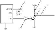
本发明第一实施方式涉及一种UART功能扩展电路。图2是该UART功能扩展电路的等效电路结构示意图。The first embodiment of the present invention relates to a UART function expansion circuit. FIG. 2 is a schematic diagram of an equivalent circuit structure of the UART function expansion circuit.
该UART功能扩展电路包括:含UART接口的处理器,一个或门,一个电阻,一个三极管,一个非门,一个总线。The UART function expansion circuit includes: a processor with a UART interface, an OR gate, a resistor, a triode, a NOT gate and a bus.
处理器中包括UART信号接收端、UART信号发送端和接收使能端。The processor includes a UART signal receiving end, a UART signal sending end and a receiving enabling end.
接收使能端和总线分别与或门的两个输入端连接,或门的输出端与UART信号接收端连接,电阻串接在总线和电源VDD之间。The receiving enable terminal and the bus are respectively connected to the two input terminals of the OR gate, the output terminal of the OR gate is connected to the UART signal receiving terminal, and the resistor is connected in series between the bus and the power supply VDD.
UART信号发送端连接非门的输入端,非门的输出端连接三极管的基极,该三极管的其他两极分别与地和总线连接。The UART signal sending terminal is connected to the input terminal of the NOT gate, the output terminal of the NOT gate is connected to the base of the triode, and the other two poles of the triode are respectively connected to the ground and the bus.
通过接收使能端的使能信号控制UART信号接收端接收数据和UART信号发送端发送数据,多台设备可以通过一对双绞线使用UART接口实现对等连接,同时UART驱动程序无需修改。By receiving the enable signal from the enable terminal to control the UART signal receiver to receive data and the UART signal sender to send data, multiple devices can use the UART interface to achieve peer-to-peer connection through a pair of twisted pairs, and the UART driver does not need to be modified.
如图2所示,采用或门1、电阻4、非门2和三极管3共4个元件实现UART功能扩展的电路,电阻4使得公共总线5在空闲时为弱高。通信时,总线5的波形与UART信号发送端TXD的发送信号相同,确保与标准UART协议兼容。As shown in Figure 2, the UART function expansion circuit is realized by four components including OR
或门1可以用来选择UART信号接收端RXD是否接收数据,接收使能端中的nRXEN信号为高时,禁止UART信号接收端接收数据,nRXEN信号为低时,允许UART信号接收端接收数据。OR
其中,或逻辑器件也称为或门,非逻辑器件也称为非门。Among them, OR logic devices are also called OR gates, and non-logic devices are also called NOT gates.
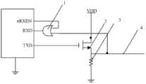
本发明第二实施方式涉及一种UART功能扩展电路。图3是该UART功能扩展等效电路的等效电路结构示意图。The second embodiment of the present invention relates to a UART function expansion circuit. FIG. 3 is a schematic structural diagram of an equivalent circuit of the UART function expansion equivalent circuit.
该UART功能扩展电路包括:The UART function expansion circuit includes:
含UART接口的处理器,一个或门,一个电阻,一个MOS管,一个非门,一个总线。A processor with a UART interface, an OR gate, a resistor, a MOS tube, a NOT gate, and a bus.
处理器中包括UART信号接收端、UART信号发送端和接收使能端。The processor includes a UART signal receiving end, a UART signal sending end and a receiving enabling end.
或门的两个输入端分别连接接收使能端和总线,或门的输出端与UART信号接收端连接,电阻串接在总线和电源VDD之间。The two input terminals of the OR gate are respectively connected to the receiving enable terminal and the bus, the output terminal of the OR gate is connected to the UART signal receiving terminal, and the resistor is connected in series between the bus and the power supply VDD.
UART信号发送端连接非门的输入端,非门的输出端连接MOS管的栅极,该MOS管的其他两极分别与地和总线连接。The UART signal sending end is connected to the input end of the NOT gate, the output end of the NOT gate is connected to the gate of the MOS transistor, and the other two poles of the MOS transistor are respectively connected to the ground and the bus.
如图3所示,采用或门1、电阻4、非门2和MOS管3共4个元件实现UART功能扩展的电路,电阻4使得公共总线5在空闲时为弱高。通信时,总线5的波形与UART信号发送端TXD的发送信号相同,确保与标准UART协议兼容。或门1可以用来选择UART信号接收端RXD是否接收数据,接收使能端中的nRXEN信号为高时,禁止UART信号接收端RXD接收数据,nRXEN信号为低时,允许UART信号接收端RXD接收数据。As shown in Figure 3, the UART function expansion circuit is realized by four components including OR
其中,或逻辑器件也称为或门,非逻辑器件也称为非门。Among them, OR logic devices are also called OR gates, and non-logic devices are also called NOT gates.
本发明第三实施方式涉及一种UART功能扩展电路。图4是该UART功能扩展等效电路的等效电路结构示意图。The third embodiment of the present invention relates to a UART function expansion circuit. FIG. 4 is a schematic structural diagram of an equivalent circuit of the UART function expansion equivalent circuit.
该UART功能扩展电路包括:The UART function expansion circuit includes:
含UART接口的处理器,一个或门,一个电阻,一个三极管,一个总线。A processor with a UART interface, an OR gate, a resistor, a transistor, and a bus.
处理器中包括UART信号接收端、UART信号发送端和接收使能端。The processor includes a UART signal receiving end, a UART signal sending end and a receiving enabling end.
或门的两个输入端分别连接接收使能端和总线,该或门的输出端与UART信号接收端连接。The two input ends of the OR gate are respectively connected to the receiving enable end and the bus, and the output end of the OR gate is connected to the UART signal receiving end.
UART信号发送端连接三极管的基极,三极管的其他两级分别与电源VDD和总线连接,电阻串接在总线和地之间。The UART signal sending end is connected to the base of the triode, the other two stages of the triode are respectively connected to the power supply VDD and the bus, and the resistor is connected in series between the bus and the ground.
如图4所示,采用或门1、电阻3和三极管2共3个元件实现UART功能扩展的电路,电阻3使得公共总线4在空闲时为弱高。通信时,总线4的波形与UART信号发送端TXD的发送信号相同,确保与标准UART协议兼容。或门1可以用来选择UART信号接收端RXD是否接收数据,接收使能端中的nRXEN信号为高时,禁止UART信号接收端RXD接收数据,nRXEN信号为低时,允许UART信号接收端RXD接收数据。As shown in Figure 4, the UART function expansion circuit is realized by using
其中,或逻辑器件也称为或门。Among them, OR logic devices are also called OR gates.
本发明第四实施方式涉及一种UART功能扩展电路。图5是该UART功能扩展等效电路的等效电路结构示意图。The fourth embodiment of the present invention relates to a UART function expansion circuit. FIG. 5 is a schematic structural diagram of an equivalent circuit of the UART function expansion equivalent circuit.
该UART功能扩展电路包括:The UART function expansion circuit includes:
含UART接口的处理器,一个或门,一个电阻,一个MOS管,一个总线。A processor with a UART interface, an OR gate, a resistor, a MOS tube, and a bus.
处理器中包括UART信号接收端、UART信号发送端和接收使能端。The processor includes a UART signal receiving end, a UART signal sending end and a receiving enabling end.
或门的两个输入端分别连接接收使能端和总线,该或门的输出端与UART信号接收端连接。The two input ends of the OR gate are respectively connected to the receiving enable end and the bus, and the output end of the OR gate is connected to the UART signal receiving end.
UART信号发送端连接MOS管的栅极,该MOS管的其他两极分别与电源VDD和总线连接,电阻串接在总线和地之间。The UART signal sending end is connected to the gate of the MOS transistor, the other two poles of the MOS transistor are respectively connected to the power supply VDD and the bus, and the resistor is connected in series between the bus and the ground.
如图5所示,采用或门1、电阻3和MOS管2共3个元件实现UART功能扩展的电路,电阻3使得公共总线4在空闲时为弱高。通信时,总线5的波形与UART信号发送端TXD的发送信号相同,确保与标准UART协议兼容。或门1可以用来选择UART信号接收端RXD是否接收数据,接收使能端中的nRXEN信号为高时,禁止UART信号接收端RXD接收数据,nRXEN信号为低时,允许UART信号接收端RXD接收数据。As shown in Figure 5, the UART function expansion circuit is realized by using
其中,或逻辑器件也称为或门。Among them, OR logic devices are also called OR gates.
本发明第五实施方式涉及一种UART功能扩展电路的控制方法。该UART功能扩展电路的控制方法用于控制如权利要求1至4中任一项的UART功能扩展电路,包括以下步骤:The fifth embodiment of the present invention relates to a control method of a UART function expansion circuit. The control method of this UART function expansion circuit is used to control the UART function expansion circuit as any one of
当UART信号发送端需要发送数据时,将接收使能端中的接收使能信号置为高电平。When the UART signal sending end needs to send data, the receiving enabling signal in the receiving enabling end is set to a high level.
当UART信号接收端需要接收数据时,将接收使能端中的接收使能信号置为低电平。When the UART signal receiving end needs to receive data, the receiving enabling signal in the receiving enabling end is set to a low level.
当UART信号发送端需要发送数据时,将接收使能端中的接收使能信号置为高电平,当UART信号接收端需要接收数据时,将接收使能端中的接收使能信号置为低电平,在该UART功能扩展电路通信时,使得总线的波形与UART信号发送端的信号波形相同,确保与标准的UART协议兼容。通过对UART原有接口的简单扩展实现接收信号和发送信号在同一条总线的复用,并允许多台设备通过同一总线实现对等互联。When the UART signal sending end needs to send data, set the receiving enable signal in the receiving enabling end to high level, and when the UART signal receiving end needs to receive data, set the receiving enabling signal in the receiving enabling end to Low level, when the UART function expansion circuit communicates, the waveform of the bus is the same as the signal waveform of the UART signal sending end, ensuring compatibility with the standard UART protocol. Through the simple expansion of the original interface of UART, the multiplexing of receiving signals and sending signals on the same bus is realized, and multiple devices are allowed to realize peer-to-peer interconnection through the same bus.
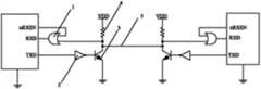
本发明第六实施方式涉及一种采用UART功能扩展电路的系统。图6是该采用UART功能扩展电路的系统的结构示意图。The sixth embodiment of the present invention relates to a system using a UART function expansion circuit. FIG. 6 is a schematic structural diagram of the system using the UART function expansion circuit.
该采用UART功能扩展电路的系统包括:The system using UART function expansion circuit includes:
由同一根总线连接的至少两个如权利要求1至4中任一项的UART功能扩展电路。At least two UART function expansion circuits according to any one of
虽然通过参照本发明的某些优选实施方式,已经对本发明进行了图示和描述,但本领域的普通技术人员应该明白,可以在形式上和细节上对其作各种改变,而不偏离本发明的精神和范围。Although the present invention has been illustrated and described with reference to certain preferred embodiments thereof, it will be understood by those skilled in the art that various changes in form and details may be made therein without departing from the present invention. The spirit and scope of the invention.
Claims (6)
Priority Applications (1)
| Application Number | Priority Date | Filing Date | Title |
|---|---|---|---|
| CN201210046415.3ACN102545953B (en) | 2012-02-27 | 2012-02-27 | UART (Universal Asynchronous Receiver/Transmitter) function extension circuit and control method thereof |
Applications Claiming Priority (1)
| Application Number | Priority Date | Filing Date | Title |
|---|---|---|---|
| CN201210046415.3ACN102545953B (en) | 2012-02-27 | 2012-02-27 | UART (Universal Asynchronous Receiver/Transmitter) function extension circuit and control method thereof |
Publications (2)
| Publication Number | Publication Date |
|---|---|
| CN102545953A CN102545953A (en) | 2012-07-04 |
| CN102545953Btrue CN102545953B (en) | 2014-03-26 |
Family
ID=46352013
Family Applications (1)
| Application Number | Title | Priority Date | Filing Date |
|---|---|---|---|
| CN201210046415.3AExpired - Fee RelatedCN102545953B (en) | 2012-02-27 | 2012-02-27 | UART (Universal Asynchronous Receiver/Transmitter) function extension circuit and control method thereof |
Country Status (1)
| Country | Link |
|---|---|
| CN (1) | CN102545953B (en) |
Families Citing this family (3)
| Publication number | Priority date | Publication date | Assignee | Title |
|---|---|---|---|---|
| CN105472782B (en)* | 2015-12-28 | 2019-04-16 | 浙江方大智控科技有限公司 | A kind of wireless communication terminal |
| CN106372017B (en)* | 2016-08-30 | 2019-11-29 | 北京奇艺世纪科技有限公司 | A kind of embedded device and serial ports receive-transmit system |
| CN114328335B (en)* | 2021-12-17 | 2023-11-07 | 武汉天常乐科技有限公司 | Method for extending UART communication interface by intelligent home gateway |
Citations (2)
| Publication number | Priority date | Publication date | Assignee | Title |
|---|---|---|---|---|
| CN1728052A (en)* | 2005-01-13 | 2006-02-01 | 中国科学院长春光学精密机械与物理研究所 | Interface device between digital signal processor and standard computer keyboard |
| CN101674074A (en)* | 2009-09-29 | 2010-03-17 | 福建师范大学 | Monobus interface conversion circuit of self-adaptive level |
Family Cites Families (1)
| Publication number | Priority date | Publication date | Assignee | Title |
|---|---|---|---|---|
| EP1985079B1 (en)* | 2006-02-09 | 2011-07-06 | Freescale Semiconductor, Inc. | Lin bus network, integrated circuit and method of communicating thereon |
- 2012
- 2012-02-27CNCN201210046415.3Apatent/CN102545953B/ennot_activeExpired - Fee Related
Patent Citations (2)
| Publication number | Priority date | Publication date | Assignee | Title |
|---|---|---|---|---|
| CN1728052A (en)* | 2005-01-13 | 2006-02-01 | 中国科学院长春光学精密机械与物理研究所 | Interface device between digital signal processor and standard computer keyboard |
| CN101674074A (en)* | 2009-09-29 | 2010-03-17 | 福建师范大学 | Monobus interface conversion circuit of self-adaptive level |
Also Published As
| Publication number | Publication date |
|---|---|
| CN102545953A (en) | 2012-07-04 |
Similar Documents
| Publication | Publication Date | Title |
|---|---|---|
| CN107770021B (en) | Home bus system HBS circuit, signal conversion method and device | |
| CN105141491B (en) | RS485 communication circuit and method for realizing spontaneous self-receiving | |
| CN101464848A (en) | Serial bus expansion method and apparatus | |
| CN104641578B (en) | DC level detection circuit, including the system and method of manufacturing and using the circuit | |
| CN106528484A (en) | Serial communication method | |
| CN102545953B (en) | UART (Universal Asynchronous Receiver/Transmitter) function extension circuit and control method thereof | |
| CN201215974Y (en) | Non-polarity communication interface | |
| CN103970048A (en) | RS485 communication receiving and transmitting enabling control circuit | |
| CN111198833B (en) | Serial Universal Input/Output System | |
| JP4722907B2 (en) | Universal serial bus transmitter | |
| EP1860815A1 (en) | Data transmission method and transmission circuit thereof | |
| CN211956465U (en) | TTL and RS232 support double-level serial port extension circuit | |
| CN1964245A (en) | RS485 character-oriented anti-interference device against idle synchronous serial communication bus | |
| CN106372017B (en) | A kind of embedded device and serial ports receive-transmit system | |
| CN203760209U (en) | MHL cable and MHL cable hot plug detecting system | |
| CN108631130B (en) | Concentrator | |
| CN103471201B (en) | Communication circuit of air conditioner | |
| CN112579490A (en) | Programmable electronic building block connecting bus | |
| TWM321548U (en) | Control device for level shift of IIC | |
| TWI519102B (en) | Flexray receiver | |
| CN114817113B (en) | A method, system, device and storage medium for judging the direction of SDA data | |
| CN204719747U (en) | The compatible equipment of Serial Peripheral Interface (SPI), Serial Peripheral Interface (SPI) and main process equipment | |
| CN105991156A (en) | Transceiver and operating method thereof | |
| CN220105684U (en) | USB data transmission circuit and terminal equipment | |
| CN114063506B (en) | Device for switching communication modes |
Legal Events
| Date | Code | Title | Description |
|---|---|---|---|
| C06 | Publication | ||
| PB01 | Publication | ||
| C10 | Entry into substantive examination | ||
| SE01 | Entry into force of request for substantive examination | ||
| ASS | Succession or assignment of patent right | Owner name:SHANGHAI ADVANCED RESEARCH INSTITUTE, CHINESE ACAD Free format text:FORMER OWNER: SHANGHAI ZHONGKE INSTITUTE FOR ADVANCED STUDY Effective date:20130923 | |
| C41 | Transfer of patent application or patent right or utility model | ||
| COR | Change of bibliographic data | Free format text:CORRECT: ADDRESS; FROM: 201210 PUDONG NEW AREA, SHANGHAI TO: 201203 PUDONG NEW AREA, SHANGHAI | |
| TA01 | Transfer of patent application right | Effective date of registration:20130923 Address after:201203 Shanghai city Pudong New Area Hartcourt Road No. 99 Applicant after:SHANGHAI ADVANCED Research Institute CHINESE ACADEMY OF SCIENCES Address before:201210 Shanghai city Pudong New Area Hartcourt Road No. 99 Applicant before:SHANGHAI ADVANCED Research Institute CHINESE ACADEMY OF SCIENCES | |
| GR01 | Patent grant | ||
| GR01 | Patent grant | ||
| TR01 | Transfer of patent right | ||
| TR01 | Transfer of patent right | Effective date of registration:20200617 Address after:Room 201-209, 21 / F, No.11, Panxi 7th Branch Road, Jiangbei District, Chongqing Patentee after:Chongqing Ziqiu Software Co.,Ltd. Address before:201203 Shanghai city Pudong New Area Hartcourt Road No. 99 Patentee before:SHANGHAI ADVANCED Research Institute CHINESE ACADEMY OF SCIENCES | |
| CF01 | Termination of patent right due to non-payment of annual fee | ||
| CF01 | Termination of patent right due to non-payment of annual fee | Granted publication date:20140326 |