CN102544171A - Multi-band light collection and energy conversion module - Google Patents
Multi-band light collection and energy conversion moduleDownload PDFInfo
- Publication number
- CN102544171A CN102544171ACN2010106092329ACN201010609232ACN102544171ACN 102544171 ACN102544171 ACN 102544171ACN 2010106092329 ACN2010106092329 ACN 2010106092329ACN 201010609232 ACN201010609232 ACN 201010609232ACN 102544171 ACN102544171 ACN 102544171A
- Authority
- CN
- China
- Prior art keywords
- light
- energy conversion
- multiband
- power conversion
- conversion module
- Prior art date
- Legal status (The legal status is an assumption and is not a legal conclusion. Google has not performed a legal analysis and makes no representation as to the accuracy of the status listed.)
- Pending
Links
Images


Classifications
- H—ELECTRICITY
- H10—SEMICONDUCTOR DEVICES; ELECTRIC SOLID-STATE DEVICES NOT OTHERWISE PROVIDED FOR
- H10F—INORGANIC SEMICONDUCTOR DEVICES SENSITIVE TO INFRARED RADIATION, LIGHT, ELECTROMAGNETIC RADIATION OF SHORTER WAVELENGTH OR CORPUSCULAR RADIATION
- H10F77/00—Constructional details of devices covered by this subclass
- H10F77/40—Optical elements or arrangements
- H10F77/42—Optical elements or arrangements directly associated or integrated with photovoltaic cells, e.g. light-reflecting means or light-concentrating means
- H10F77/484—Refractive light-concentrating means, e.g. lenses
- H—ELECTRICITY
- H10—SEMICONDUCTOR DEVICES; ELECTRIC SOLID-STATE DEVICES NOT OTHERWISE PROVIDED FOR
- H10F—INORGANIC SEMICONDUCTOR DEVICES SENSITIVE TO INFRARED RADIATION, LIGHT, ELECTROMAGNETIC RADIATION OF SHORTER WAVELENGTH OR CORPUSCULAR RADIATION
- H10F77/00—Constructional details of devices covered by this subclass
- H10F77/40—Optical elements or arrangements
- H10F77/42—Optical elements or arrangements directly associated or integrated with photovoltaic cells, e.g. light-reflecting means or light-concentrating means
- H10F77/492—Spectrum-splitting means, e.g. dichroic mirrors
- Y—GENERAL TAGGING OF NEW TECHNOLOGICAL DEVELOPMENTS; GENERAL TAGGING OF CROSS-SECTIONAL TECHNOLOGIES SPANNING OVER SEVERAL SECTIONS OF THE IPC; TECHNICAL SUBJECTS COVERED BY FORMER USPC CROSS-REFERENCE ART COLLECTIONS [XRACs] AND DIGESTS
- Y02—TECHNOLOGIES OR APPLICATIONS FOR MITIGATION OR ADAPTATION AGAINST CLIMATE CHANGE
- Y02E—REDUCTION OF GREENHOUSE GAS [GHG] EMISSIONS, RELATED TO ENERGY GENERATION, TRANSMISSION OR DISTRIBUTION
- Y02E10/00—Energy generation through renewable energy sources
- Y02E10/50—Photovoltaic [PV] energy
- Y02E10/52—PV systems with concentrators
Landscapes
- Photovoltaic Devices (AREA)
- Diffracting Gratings Or Hologram Optical Elements (AREA)
Abstract
Description
Translated fromChinese技术领域technical field
本发明涉及一种集光及能量转换模块,特别是一种能将太阳或其它光线依其波长集光并进行能量转换的模块。The invention relates to a light collection and energy conversion module, in particular to a module capable of collecting light from the sun or other light according to its wavelength and performing energy conversion.
背景技术Background technique
现今有许多太阳能电池的技术,但是目前没有一种太阳能电池的吸收频谱能完全吻合太阳光的发光频谱。There are many solar cell technologies today, but none of the solar cell's absorption spectrum can completely match the sunlight's emission spectrum.
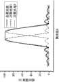
图1为太阳光(AM 1.5G)的发光频谱。图2为列举三种不同的太阳能电池对太阳光具有不同的吸收频谱。参照图1及图2,大部分的太阳能电池仅能吸收某些特定波段的太阳光。Figure 1 is the luminescence spectrum of sunlight (AM 1.5G). FIG. 2 shows three different solar cells with different absorption spectrums for sunlight. Referring to FIG. 1 and FIG. 2, most solar cells can only absorb certain specific wavelengths of sunlight.
因此,在现有的太阳能电池的技术上,使得太阳光无法被有效地利用,需要多波段太阳能吸收技术,以更加有效地利用不同波段的太阳能。Therefore, in the existing solar cell technology, sunlight cannot be effectively utilized, and multi-band solar energy absorption technology is required to more effectively utilize solar energy of different bands.
传统多波段太阳能吸收技术所使用的是垂直堆栈技术,即串接式太阳电池(tandem solar cell)。串接式太阳电池是将两个或三个不同的太阳能电池在垂直方向上堆栈在一起,以增加太阳能电池的吸收频谱。但是由于材料本身的穿透率,越下层的材料层的通光量会越低,因而降低其吸光量。The traditional multi-band solar absorption technology uses a vertical stack technology, that is, tandem solar cells. The tandem solar cell is to stack two or three different solar cells together in the vertical direction to increase the absorption spectrum of the solar cell. However, due to the transmittance of the material itself, the lower the material layer, the lower the light transmission, thus reducing its light absorption.
并且,具有不同吸收频谱的太阳能电池具有不同的晶格常数(latticeconstant)。晶格常数的不匹配容易在交界处产生一些缺陷,因而影响其光电流的收集。因此,在交界处则需多堆栈一层材料,以降低交界处的电阻值,同时解决晶格常数不匹配的问题,但是却相对地增加了制作的成本和复杂度。于垂直堆栈技术上,可堆栈三个太阳能电池和四个太阳能电池,但是随着堆栈层数的增加,制作的成本和复杂度也随着增加,而提升的效率不一定呈线性的增加,并影响工艺的成品率。Also, solar cells with different absorption spectra have different lattice constants. The mismatch of lattice constants tends to generate some defects at the junction, thus affecting its photocurrent collection. Therefore, an additional layer of material needs to be stacked at the junction to reduce the resistance value of the junction and solve the problem of lattice constant mismatch, but relatively increases the cost and complexity of fabrication. In terms of vertical stacking technology, three solar cells and four solar cells can be stacked, but as the number of stacked layers increases, the cost and complexity of manufacturing also increase, and the improved efficiency does not necessarily increase linearly, and Affects the yield of the process.
于太阳能电池缺料的压力下,集光器的使用便略显重要。集光比的定义为集光器的受光面积比上在聚光斑上所放置太阳能电池的受光面积。当具有越高集光比的太阳能发电系统,所使用的太阳能电池材料也会越少。Under the pressure of shortage of solar cell materials, the use of light collectors is slightly more important. The light collection ratio is defined as the ratio of the light receiving area of the light collector to the light receiving area of the solar cell placed on the light spot. When the solar power generation system has a higher light collection ratio, less solar cell material is used.
在一现有技术上,利用拱形菲涅尔透镜(arched Fresnel lens)将太阳光集光到太阳能电池上,以提高入射光的强度并降低太阳能材料的使用率。但是太阳能电池的吸收频谱有别于太阳光的发光频谱,未吸收的太阳能会转换成热能,因而提高了太阳能电池基板的温度,如此一来便降低了太阳能电池的转换效率。因此需要额外设计散热片。但是散热片的设计却增加了太阳能发电系统的成本与复杂度。In a prior art, arched Fresnel lenses are used to collect sunlight onto solar cells to increase the intensity of incident light and reduce the usage rate of solar materials. However, the absorption spectrum of solar cells is different from the emission spectrum of sunlight. Unabsorbed solar energy will be converted into heat energy, thereby increasing the temperature of the solar cell substrate, thus reducing the conversion efficiency of the solar cell. Therefore, an additional heat sink needs to be designed. However, the design of the heat sink increases the cost and complexity of the solar power generation system.
在另一现有技术上,则采用离轴菲涅尔透镜(off-axis Fresnel lens)的设计。根据离轴菲涅尔透镜的设计原理,不同波长会因为高色散材质的特性,而集光在光入射轴向(axial direction)上不同的位置。接着,将不同的太阳能电池放置于光入射轴向的附近,使得不同波长的光可以被不同的太阳能电池吸收。但如此的设计会造成入射光会具有较大的入射角度而影响收光效率,并且高色散材质具有不易取得的问题。In another prior art, an off-axis Fresnel lens design is adopted. According to the design principle of the off-axis Fresnel lens, different wavelengths will collect light at different positions on the axial direction of light incidence due to the characteristics of high dispersion materials. Next, different solar cells are placed near the light incident axis, so that light of different wavelengths can be absorbed by different solar cells. However, such a design will cause the incident light to have a large incident angle, which will affect the light collection efficiency, and the high dispersion material is difficult to obtain.
相关技术与研究可参考US6281426、US5498297及US4204881等美国专利。Related technologies and research can refer to US patents such as US6281426, US5498297 and US4204881.
发明内容Contents of the invention
本发明所要解决的技术问题是提供一种多波段集光及能量转换模块,以解决现有技术所存在的问题。The technical problem to be solved by the present invention is to provide a multi-band light collection and energy conversion module to solve the problems existing in the prior art.
为了实现上述目的,本发明提供了一种多波段集光及能量转换模块,包括多波段集光器和能量转换组件组。In order to achieve the above object, the present invention provides a multi-band light collection and energy conversion module, which includes a multi-band light collector and an energy conversion assembly.
多波段集光器包括光栅与集光组件。光栅位于集光组件的表面上。能量转换组件组包含多个能量转换组件。该些能量转换组件侧边相邻地设置在集光组件的集光平面上,且能量转换组件的收光面面向集光组件。The multi-band light collector includes a grating and light collection components. A grating is located on the surface of the light collecting assembly. The energy conversion component group contains a plurality of energy conversion components. The sides of the energy conversion components are adjacently arranged on the light collection plane of the light collection component, and the light collection surface of the energy conversion component faces the light collection component.
为了更好地实现上述目的,本发明还提供了一种多波段集光及能量转换模块,包括一多波段集光器与一能量转换组件组。多波段集光器将入射光源依波长分光与集光,其包括一光栅与集光组件。光栅可将入射光源依波长分光。集光组件可将入射光源集光于一集光面上。能量转换组件组包含多个能量转换组件,能量转换组件设置在集光组件的集光面上,且能量转换组件组的一收光面面向集光组件。其中,入射光源先经过多波段集光器的分光与集光后,形成不同波段的多个光束入射到能量转换组件组。In order to better achieve the above object, the present invention also provides a multi-band light collection and energy conversion module, which includes a multi-band light collector and an energy conversion assembly. The multi-band light collector splits and collects the incident light source according to the wavelength, which includes a grating and light collection components. A grating splits an incident light source into wavelengths. The light collecting component can collect the incident light source on a light collecting surface. The energy conversion component set includes a plurality of energy conversion components, the energy conversion components are arranged on the light collection surface of the light collection component, and a light collection surface of the energy conversion component set faces the light collection component. Wherein, after the incident light source passes through the multi-band light collector for light splitting and light collection, multiple light beams of different wave bands are formed to enter the energy conversion component group.
为了更好地实现上述目的,本发明还提供了一种多波段集光及能量转换模块,包括一多波段集光器与一能量转换组件组。多波段集光器将一入射光源依波长分光与集光于多个聚光斑。能量转换组件组包含多个能量转换组件,能量转换组件个别对应并配置于聚光斑处,能量转换组件具有个别的吸收频谱峰值,且每一能量转换组件的吸收频谱峰值对应于能量转换组件所在聚光斑的一光束的波长。In order to better achieve the above object, the present invention also provides a multi-band light collection and energy conversion module, which includes a multi-band light collector and an energy conversion assembly. The multi-wavelength concentrator divides and concentrates an incident light source into multiple spots according to the wavelength. The energy conversion component group includes a plurality of energy conversion components, and the energy conversion components are individually corresponding and arranged at the spot. The energy conversion components have individual absorption spectrum peaks, and the absorption spectrum peak value of each energy conversion component corresponds to the concentration The wavelength of a beam of light in the spot.
本发明的技术效果在于:根据本发明的多波段集光及能量转换模块,利用多波段集光器(集光组件和光栅)将太阳光或其它光线(即入射光源)分出不同波段的光束,并使其集光于各自对应的能量转换组件,以使能量转换组件能转换其所对应波长的光束,而得到良好的能量转换效率,进而提升总能量转换效率。并且,多波段集光器的使用还可降低能量转换组件材料的使用率。再者,集光后的太阳光或其它光线可以小角度入射至能量转换组件,可降低太阳光或其它光线的反射率。The technical effect of the present invention is: according to the multi-band light collection and energy conversion module of the present invention, the sunlight or other light (i.e. incident light source) is separated into beams of different wave bands by using the multi-band light collector (light collection assembly and grating) , and make them collect light on their corresponding energy conversion components, so that the energy conversion components can convert the light beams of their corresponding wavelengths, so as to obtain good energy conversion efficiency, and then improve the total energy conversion efficiency. Moreover, the use of the multi-band light collector can also reduce the usage rate of the material of the energy conversion component. Furthermore, the collected sunlight or other light can be incident on the energy conversion component at a small angle, which can reduce the reflectivity of the sunlight or other light.
以下结合附图和具体实施例对本发明进行详细描述,但不作为对本发明的限定。The present invention will be described in detail below in conjunction with the accompanying drawings and specific embodiments, but not as a limitation of the present invention.
附图说明Description of drawings
图1为显示太阳光(AM 1.5G)的发光频谱;Figure 1 shows the luminescence spectrum of sunlight (AM 1.5G);
图2为显示三种能量转换组件的吸收频谱;Figure 2 shows the absorption spectra of three energy conversion components;
图3为本发明第一实施例的多波段集光及能量转换模块的结构示意图;3 is a schematic structural diagram of a multi-band light collection and energy conversion module according to the first embodiment of the present invention;
图4为本发明第二实施例的多波段集光及能量转换模块的结构示意图;4 is a schematic structural diagram of a multi-band light collection and energy conversion module according to a second embodiment of the present invention;
图5为本发明第三实施例的多波段集光及能量转换模块的结构示意图;5 is a schematic structural diagram of a multi-band light collection and energy conversion module according to a third embodiment of the present invention;
图6为本发明第四实施例的多波段集光及能量转换模块的结构示意图;6 is a schematic structural diagram of a multi-band light collection and energy conversion module according to a fourth embodiment of the present invention;
图7为本发明第五实施例的多波段集光及能量转换模块的结构示意图;7 is a schematic structural diagram of a multi-band light collection and energy conversion module according to a fifth embodiment of the present invention;
图8为本发明第六实施例的多波段集光及能量转换模块的结构示意图;8 is a schematic structural diagram of a multi-band light collection and energy conversion module according to the sixth embodiment of the present invention;
图9为一本发明的实施例的多波段集光及能量转换模块的结构示意图;9 is a schematic structural diagram of a multi-band light collection and energy conversion module according to an embodiment of the present invention;
图10为一实施例的光栅的细部结构示意图;FIG. 10 is a schematic diagram of a detailed structure of a grating in an embodiment;
图11为一实施例的次聚光斑与总聚光斑的示意图;Fig. 11 is a schematic diagram of a sub-focus spot and a total focus spot of an embodiment;
图12为本发明多个第一实施例的多波段集光及能量转换模块的结构示意图;Fig. 12 is a schematic structural diagram of multi-band light collection and energy conversion modules in multiple first embodiments of the present invention;
图13为本发明第七实施例的多波段集光及能量转换模块的结构示意图。13 is a schematic structural diagram of a multi-band light collection and energy conversion module according to a seventh embodiment of the present invention.
其中,附图标记Among them, reference signs
10太阳能发电系统10 Solar power generation system
100、100-1、100-2、100-3多波段集光及能量转换模块100, 100-1, 100-2, 100-3 multi-band light collection and energy conversion modules
102太阳光102 sunlight
110、110-1、110-2、110-3多波段集光器110, 110-1, 110-2, 110-3 multi-band optical collector
112集光组件112 light collecting components
112a出射面112a exit surface
112b入射面112b incident surface
114光栅114 grating
115、116次光栅115, 116 raster
130能量转换组件组130 energy conversion component groups
130a收光面130a receiving surface
130-1,130-2,130-3能量转换组件组130-1, 130-2, 130-3 energy conversion component group
131、132、133能量转换组件131, 132, 133 energy conversion components
140二次镜140 secondary mirror
A集光面A set glossy surface
D、D’宽度D, D'width
d周期d cycle
L光轴L optical axis
λ1、λ2、λ3波长λ1, λ2, λ3 wavelength
H1、H2、H3连线H1, H2, H3 connection
TL切线TL Tangent
T厚度T thickness
具体实施方式Detailed ways
下面结合附图对本发明的结构原理和工作原理作具体的描述:Below in conjunction with accompanying drawing, structural principle and working principle of the present invention are specifically described:
于本发明中,利用多波段集光器将入射光源如太阳光或其它光线,分出不同波段的光束,并使其集光在光入射横向上不同的位置,以形成不同的聚光斑。前述不同波段的光束可以是指在不同光频谱范围区间,或指特定光波长。以下为了便于说明,将以太阳光为例,但本发明并不以此为限,也可为环境光或其它光线。In the present invention, the incident light source, such as sunlight or other light rays, is separated into beams of different wavelength bands by using a multi-band concentrator, and the light is collected at different positions in the transverse direction of light incidence to form different spotlights. The foregoing light beams of different wavelength bands may refer to intervals in different optical spectrum ranges, or refer to specific optical wavelengths. For the convenience of description, sunlight will be used as an example below, but the present invention is not limited thereto, and may also be ambient light or other light.
接着,在各个聚光斑上,设置对应的能量转换组件。此处的能量转换组件可以是但不限于光电转换组件或热电转换组件。前述对应设置,可以是将前述的能量转换组件的吸收频谱峰值与聚光斑的光束的波段(波长)相对应(注:能量转换组件对太阳光具有不同的吸收频谱峰值),举例而言,若能量转换组件吸收频谱峰值为500奈米(nm),则将之配置于光束的光波段涵盖此峰值的聚光斑处即可。如此一来,各能量转换组件即可具有良好的转换效率,进而提升总能量转换效率。同时,又可降低热能的产生。于此,由于多波段集光器具有集光的特性,因此可以提高多波段集光器的集光比,以及降低能量转换组件材料的使用率。Next, on each spot of light, a corresponding energy conversion component is set. The energy conversion component here may be, but not limited to, a photoelectric conversion component or a thermoelectric conversion component. The aforementioned corresponding setting may be to correspond the peak absorption spectrum of the aforementioned energy conversion component to the band (wavelength) of the light beam of the spot spot (note: the energy conversion component has different peak absorption spectrum for sunlight), for example, if The absorption spectrum peak of the energy conversion component is 500 nanometers (nm), so it can be arranged at the spot where the light band of the light beam covers this peak. In this way, each energy conversion component can have good conversion efficiency, thereby improving the total energy conversion efficiency. At the same time, the generation of heat energy can be reduced. Herein, since the multi-band light collector has the characteristic of collecting light, the light collection ratio of the multi-band light collector can be increased, and the usage rate of the material of the energy conversion component can be reduced.
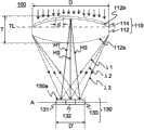
图3为根据本发明的多波段集光及能量转换模块的示意图。多波段集光及能量转换模块100包括多波段集光器110和能量转换组件组130。多波段集光器110包括一光栅114和集光组件112。其中,光栅114位于集光组件112的一表面上。多波段集光器110的集光组件112将入射光源集光于一集光面A上。光栅114将入射于多波段集光器110的入射光源依波段分光,以形成多个光束,例如可将入射的太阳光102依据不同的波长λ1、λ2和λ3分为三波段光束。此三波段光束虽为特定波长为例,但并不以此为限,也可以是三个相异波长范围的波段光束,例如以λ1、λ2和λ3为中心波长的三个波段的光束。至于多波段集光器110先将太阳光102分光再进行集光,或先进行集光再分光,均能实现本发明的目的。本实施例先行分光后再集光。Fig. 3 is a schematic diagram of a multi-band light collection and energy conversion module according to the present invention. The multi-band light collection and
前述的集光面A在本实施例中虽以一平面方式示意,但并不以此为限,集光面A也可以是对应集光组件112的集光特性而变化,例如一曲面或依续连接的多个线段。Although the aforementioned light-collecting surface A is illustrated as a plane in this embodiment, it is not limited thereto. The light-collecting surface A can also be changed corresponding to the light-collecting characteristics of the light-collecting
能量转换组件组130包含有多个光电转换组件或热电转换组件,前述的多个能量转换组件对光线(光能量)具有不同的吸收频谱峰值。在本实施例中,能量转换组件组130包含三个能量转换组件131、132、133,且能量转换组件131、132、133具有不同的吸收波段(吸收频谱峰值)。该些能量转换组件131、132、133侧边相邻地设置,各个能量转换组件132/133的吸收波段可接续相邻配置的前一能量转换组件131/132的吸收波段,即能量转换组件131、132、133的吸收波段不重叠。能量转换组件组130设置于集光组件112的集光面A上,且能量转换组件组130的收光面130a(即各能量转换组件131、132、133的收光面130a)面向集光组件112,使集光后的光线能入射至能量转换组件131、132、133中。要说的是,在此虽列举能量转换组件组130的能量转换组件131、132、133侧边相邻设置为例,但并不以此为限,只要能量转换组件组130设置在集光组件112的集光面A上,使集光后的光线能入射至能量转换组件组130中即可。此外,集光面A可与集光组件112的光轴L形成一夹角。此夹角可介于60度到120度之间。在一实施例中,集光面A可大致上垂直于集光组件112的光轴L。The energy
依本实施例,太阳光经过光栅114及集光组件112后会形成具有相异波段的多个光束,这些光束在集光面A上形成聚光斑,而各能量转换组件131、132、133则依其吸收光谱峰值对应配置于各光束所形成的聚光斑位置,因此,能量转换组件131、132、133另一列举配置方式则是将各能量转换组件131、132、133收光面130a的中心轴(即为其垂直入射的轴)对应于各光束的光轴,意即,能量转换组件131、132、133收光面130a的中心轴与与其对应的光束的光轴L间的夹角在0度到20度之间(或160度到180度之间),能得到良好的收光效果,进一步提升能量转换效率。According to this embodiment, after the sunlight passes through the grating 114 and the
集光组件112包含一出射面112a与一入射面112b,其中入射面112b用以接收入射光源,经由出射面112a出光并集光于集光面A上。其中,集光组件112的出射面112a的大小可覆盖能量转换组件组130的收光面130a。在一实施例中,能量转换组件组130的宽度D’可小于或等于集光组件112的宽度D的二分之一。在另一实施例中,能量转换组件组130的收光面130a小于或等于集光组件112的出射面112a垂直投影在水平面上的面积的二分之一。The
光栅114可贴合或制作于集光组件112的一侧的表面上。换言之,集光组件112和光栅114可为独立的两组件,或者为一体成型的单一构件。如图3所示,光栅114贴合于集光组件112的入射面112b上。此外,集光组件112可为透镜,在本实施例中,该集光组件112为一双凸透镜,但不以此为限。The grating 114 can be bonded or fabricated on one surface of the
当太阳光102进入到多波段集光及能量转换模块100时,会先经过多波段集光器110,经由多波段集光器110的分光与集光后,形成多个不同波段的光束入射到能量转换组件组130。在图3的实施例中,太阳光102经过多波段集光器110时,首先进入到光栅114,将入射的太阳光102分光为三个不同波长的光束,并经由入射面112b入射至集光组件112,分光后的光束于集光组件112集光后,会经由出射面112a的出光,而在集光面A上依不同波长(λ1、λ2和λ3)集光到不同的聚光斑上。能量转换组件组130中的能量转换组件131、132、133设置在这些聚光斑上。详细来说,各能量转换组件131、132、133设置在其相对应吸收频谱峰值的不同波段光束的聚光斑上。即,能量转换组件131、132、133的吸收频谱峰值会相应于形成其设置处上的聚光斑的光的波长(λ1、λ2和λ3)。换言之,能量转换组件131、132、133的吸收波段会包含对应的波长(λ1、λ2或λ3)。或者是,对应的波长(λ1、λ2或λ3)位于能量转换组件131、132或133的吸收频谱的中央。When
于此,集光组件112可致使太阳光102(即入射光源)在集光后以小角度的入射角入射至各个能量转换组件131、132、133。在一实施例中,此入射角可介于一30度到30度之间。此处的入射角指入射的光束与能量转换组件131、132、133收光面130a的法线之间的夹角。Here, the
请参考图4,与图3的实施例不同之处在于,本实施例所采用的集光组件112为平凸透镜。同样地,当太阳光102进入到多波段集光及能量转换模块100时,会先经过多波段集光器110,经由多波段集光器110的分光与集光后,形成多个不同波段的光束入射到能量转换组件组130。Please refer to FIG. 4 , the difference from the embodiment in FIG. 3 is that the
请参考图5,与图3、图4的实施例不同之处在于,本实施例所采用的集光组件112为菲涅尔透镜(Fresnel lens)。在一实施例中,菲涅尔透镜可使用二维集光式菲涅尔透镜。此外,菲涅尔透镜也可为一维集光式。同样地,当太阳光102进入到多波段集光及能量转换模块100时,会先经过多波段集光器110,经由多波段集光器110的分光与集光后,形成多个不同波段的光束入射到能量转换组件组130。Please refer to FIG. 5 , the difference from the embodiments of FIGS. 3 and 4 is that the
请参考图6,与图3的实施例不同之处在于,本实施例中的光栅114设置于集光组件112的出射面112a上。因此,当太阳光102进入到多波段集光器110时,首先经由入射面112b入射至集光组件112,并于集光组件112集光后,会经由出射面112a的出光,而进入到光栅114中,并将集光后的太阳光102分光为三个不同波长的光束,在集光面A上依不同波长(λ1、λ2和λ3)集光到不同的聚光斑上,而被设置在相对应位置的能量转换组件131、132、133所接收。由上述的实施例可知,在多波段集光器110中,光栅114可设置于集光组件112的入射面112b或出射面112a,并不以此为限。Please refer to FIG. 6 , the difference from the embodiment in FIG. 3 is that the grating 114 in this embodiment is disposed on the
请参考图7,与图6的实施例不同之处在于,本实施例所采用的集光组件112为平凸透镜。由于光栅114设置于集光组件112的出射面112a(即平凸透镜的平面)上,因此,在本实施例中,所使用的光栅114可为等周期光栅,即光栅114投影到平凸透镜中的曲面的切线TL的周期(间距(pitch))均相等。而图6的实施例,光栅114设置于集光组件112的出射面112a(即双凸透镜的凸面)上,所使用的光栅114也可为等周期光栅,即光栅114投影到双凸透镜的切线TL的周期(间距)均相等。要说的是,在此仅列举光栅114投影到切线TL的周期可为等周期的设计,本领域技术人员当知光栅114的周期可有不同设计的变化,并不以所列举者为限。Please refer to FIG. 7 , the difference from the embodiment in FIG. 6 is that the
请参照图8,图示为一反射式的多波段集光及能量转换模块100,与前述实施例所不同的是,太阳光102是来自于相对应于能量转换组件组130的收光面130a背面方向入光(进入多波段集光器110),而非如前述实施例的太阳光102由能量转换组件组130的收光面130a方向入光。因此,在本实施例中,采用的集光组件112可为反射式集光透镜,其中可于集光组件112的出射面112a或入射面112b形成反射面,且光栅114形成于集光组件112的出射面112a上。当太阳光102进入到多波段集光器110时,先经由光栅114的分光后,进入到集光组件112中进行集光,由于出射面112a或入射面112b为反射面,因此分光后的光束会在集光组件112中反射,并集光在集光面A上,再进入到位于集光面A的能量转换组件组130。在另一实施例中,多波段集光器110可一体成型,即集光组件112与光栅114为一体,此时,可在光栅114的表面上设置反射层,例如是涂布金属。当太阳光102进入到多波段集光器110时,会直接在光栅114中反射、集光与分光,同样使得光源集光在集光面A上。Please refer to FIG. 8, which shows a reflective multi-band light collection and
多波段集光及能量转换模块100在实际的设计上,举例来说,可参照图9,于此采用双凸透镜作为集光组件112,光栅114可设计成将入射光依照波长分光为λ1、λ2和λ3的三波段光,其中λ1=500nm、λ2=600nm以及λ3=700nm,其相对应设置在集光面A聚光斑位置的能量转换组件131、132、133,可选择如图2中的能量转换组件131、132、133,分别对于波长为500nm、600nm以及700nm的波段光具有良好的吸收系数。当太阳光102垂直入射时,多波段集光及能量转换模块100的设计条件可为集光组件112的宽度D和厚度T分别为8cm和1cm,集光组件112所使用材质的折射率为1.49、集光组件112的曲率半径(R)为12.8cm、光栅114投影到切线TL的周期d为5mm、光栅114的绕射阶数(m)为-1、能量转换组件组130的总宽度D’为1.5cm以及集光组件112的入射面112b的中心点到能量转换组件131、132、133收光面130a的中心点的连线H1、H2、H3长度分别为27.60cm、27.63cm和27.66cm,连线H1、H2、H3与收光面130a法线的夹角分别为5.74°、6.89°和8.05°。For the actual design of the multi-band light collection and
此外,参照图10,光栅114可由二个以上的次光栅115、116所构成。该些次光栅115、116可交错排列。再者,该些次光栅115、116可具有相同周期,也可具有不同周期,可依实际需求而有不同的设计。于此,各个次光栅115、116可将入射光源在集光面A上形成各自的次聚光斑,以至于透过次聚光斑的叠加来得到一中心平坦的总聚光斑,进而避免能量过度集中。换言之,对应于各个能量转换组件131、132、133的各个聚光斑可由二个以上的次聚光斑所构成。如此即可避免因能量过度集中而造成能量转换组件组130的温度上升。关于前述次聚光斑与总聚光斑的示意图请参考图11,图中的水平轴为集光面A的水平位置,垂直轴则为相对强度,从图中可以看出,多个邻近的次聚光斑集结而成一个总聚光斑(图中仅以次聚光斑1及次聚光斑2示意,但并非本发明的限制)。In addition, referring to FIG. 10 , the grating 114 may be composed of more than two
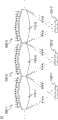
参照图12,在一太阳能发电系统10中,可设置有二个以上的多波段集光及能量转换模块100-1、100-2、100-3。Referring to FIG. 12 , in a solar
该些多波段集光及能量转换模块100-1、100-2、100-3可并排配置。即,多波段集光及能量转换模块100-1、100-2、100-3的多波段集光器110-1、110-2、110-3侧边相邻地依序配置。而不同多波段集光及能量转换模块100-1、100-2、100-3的能量转换组件组130-1、130-2、130-3则不相互邻接,即彼此间隔开。These multi-band light collection and energy conversion modules 100-1, 100-2, 100-3 can be arranged side by side. That is, the multi-band light concentrators 110-1, 110-2, and 110-3 of the multi-band light collection and energy conversion modules 100-1, 100-2, and 100-3 are sequentially arranged side by side. The energy conversion component groups 130 - 1 , 130 - 2 , 130 - 3 of different multi-band light collection and energy conversion modules 100 - 1 , 100 - 2 , 100 - 3 are not adjacent to each other, that is, they are spaced apart from each other.
根据本发明的多波段集光及能量转换模块,利用多波段集光器(集光组件和光栅)将太阳光分出不同波段的光束,并使其集光于各自对应的能量转换组件,以致使能量转换组件具有良好的转换效率,进而提升总能量转换效率。并且,多波段集光器的使用还可降低能量转换组件材料的使用率。According to the multi-band light collection and energy conversion module of the present invention, the multi-band light collector (light collection component and grating) is used to separate the sunlight into beams of different wavelength bands, and to collect the light on the respective corresponding energy conversion components, so that The energy conversion component has good conversion efficiency, thereby improving the total energy conversion efficiency. Moreover, the use of the multi-band light collector can also reduce the usage rate of the material of the energy conversion component.
最后,请参阅图13,其为根据本发明第七实施例的多波段集光及能量转换模块的结构示意图。多波段集光及能量转换模块100包括多波段集光器110、能量转换组件组130以及配置于多波段集光器110与能量转换组件组130之间的二次镜140。多波段集光器110包括光栅114和集光组件112。多波段集光器110的集光组件112将入射光源集光于一集光面A上。光栅114将入射于多波段集光器110的入射光源依波段分光为光束。二次镜140用以导引被分光与集光的光束于多个聚光斑。因此,当被集光的光束经过二次镜140后,可以减少光束入射于能量转换组件组130的入射角的偏差,而不致造成聚光斑偏离能量转换组件组130。因此,能量转换组件组130即可依据其吸收波段将入射光线做能量转换。Finally, please refer to FIG. 13 , which is a schematic structural diagram of a multi-band light collection and energy conversion module according to a seventh embodiment of the present invention. The multi-band light collection and
当然,本发明还可有其它多种实施例,在不背离本发明精神及其实质的情况下,熟悉本领域的技术人员当可根据本发明作出各种相应的改变和变形,但这些相应的改变和变形都应属于本发明所附的权利要求的保护范围。Certainly, the present invention also can have other multiple embodiments, without departing from the spirit and essence of the present invention, those skilled in the art can make various corresponding changes and deformations according to the present invention, but these corresponding Changes and deformations should belong to the scope of protection of the appended claims of the present invention.
Claims (21)
Priority Applications (5)
| Application Number | Priority Date | Filing Date | Title |
|---|---|---|---|
| CN2010106092329ACN102544171A (en) | 2010-12-21 | 2010-12-21 | Multi-band light collection and energy conversion module |
| PCT/CN2011/084110WO2012083821A1 (en) | 2010-12-21 | 2011-12-16 | Multi-band light collecting and energy conversion module |
| EP11851586.5AEP2657987A4 (en) | 2010-12-21 | 2011-12-16 | MULTIBAND LIGHT COLLECTION AND ENERGY CONVERSION MODULE |
| JP2013527466AJP2013537004A (en) | 2010-12-21 | 2011-12-16 | Multi-band concentrator / energy conversion module |
| US13/730,084US20130153000A1 (en) | 2010-12-21 | 2012-12-28 | Multi-band light collection and energy conversion module |
Applications Claiming Priority (1)
| Application Number | Priority Date | Filing Date | Title |
|---|---|---|---|
| CN2010106092329ACN102544171A (en) | 2010-12-21 | 2010-12-21 | Multi-band light collection and energy conversion module |
Publications (1)
| Publication Number | Publication Date |
|---|---|
| CN102544171Atrue CN102544171A (en) | 2012-07-04 |
Family
ID=46313158
Family Applications (1)
| Application Number | Title | Priority Date | Filing Date |
|---|---|---|---|
| CN2010106092329APendingCN102544171A (en) | 2010-12-21 | 2010-12-21 | Multi-band light collection and energy conversion module |
Country Status (5)
| Country | Link |
|---|---|
| US (1) | US20130153000A1 (en) |
| EP (1) | EP2657987A4 (en) |
| JP (1) | JP2013537004A (en) |
| CN (1) | CN102544171A (en) |
| WO (1) | WO2012083821A1 (en) |
Cited By (4)
| Publication number | Priority date | Publication date | Assignee | Title |
|---|---|---|---|---|
| CN103199139A (en)* | 2013-01-31 | 2013-07-10 | 中国科学技术大学 | Spectral diffraction optical system used for solar energy condensation |
| CN105554185A (en)* | 2015-11-27 | 2016-05-04 | 努比亚技术有限公司 | Solar energy charging system and mobile terminal |
| CN106887997A (en)* | 2017-03-29 | 2017-06-23 | 浙江晶科能源有限公司 | A kind of dispersion photovoltaic generating system |
| CN107935104A (en)* | 2018-01-05 | 2018-04-20 | 郑州大学 | Solar energy photocatalytic reactor and the photocatalysis water treatment system with the device |
Families Citing this family (5)
| Publication number | Priority date | Publication date | Assignee | Title |
|---|---|---|---|---|
| US20100175685A1 (en)* | 2008-07-14 | 2010-07-15 | Robert Owen Campbell | Advanced Tracking Concentrator Employing Rotating Input Arrangement and Method |
| FR3023977B1 (en)* | 2014-07-16 | 2017-11-24 | Thales Sa | PHOTOVOLTAIC MODULE COMPRISING A CONCENTRATION OPTIC WITH SUB-WAVELENGTH PATTERNS AND SOLAR SATELLITE GENERATOR COMPRISING SAID MODULE |
| WO2018070326A1 (en)* | 2016-10-14 | 2018-04-19 | 株式会社カネカ | Photovoltaic device |
| CN109654750B (en)* | 2018-12-28 | 2020-04-17 | 清华大学深圳研究生院 | Staggered solar light condensation system |
| WO2024157371A1 (en)* | 2023-01-25 | 2024-08-02 | 日本電信電話株式会社 | Solar battery module and conversion device |
Citations (5)
| Publication number | Priority date | Publication date | Assignee | Title |
|---|---|---|---|---|
| US20020135825A1 (en)* | 2000-07-14 | 2002-09-26 | Chih-Kung Lee | High light-sensing efficiency image sensor apparatus and method |
| US20090114266A1 (en)* | 2007-10-03 | 2009-05-07 | Biles Jonathan R | High concentration, spectrum spitting, broad bandwidth, hologram photovoltaic solar collector |
| CN101592777A (en)* | 2009-03-19 | 2009-12-02 | 苏州纳米技术与纳米仿生研究所 | Fabrication method of full-spectrum wide-angle concentrator based on nanostructure |
| CN101625458A (en)* | 2008-07-11 | 2010-01-13 | 财团法人工业技术研究院 | Composite light splitting element |
| CN101728445A (en)* | 2008-10-29 | 2010-06-09 | 张仁怀 | Solar cell with polymer multilayer film and manufacturing method thereof |
Family Cites Families (14)
| Publication number | Priority date | Publication date | Assignee | Title |
|---|---|---|---|---|
| US4204881A (en)* | 1978-10-02 | 1980-05-27 | Mcgrew Stephen P | Solar power system |
| US4418238A (en)* | 1981-10-20 | 1983-11-29 | Lidorenko Nikolai S | Photoelectric solar cell array |
| JPH04188775A (en)* | 1990-11-22 | 1992-07-07 | Sanyo Electric Co Ltd | Solar cell |
| US5153780A (en)* | 1991-06-10 | 1992-10-06 | The United States Of America As Represented By The United States Department Of Energy | Method and apparatus for uniformly concentrating solar flux for photovoltaic applications |
| US5701005A (en)* | 1995-06-19 | 1997-12-23 | Eastman Kodak Company | Color separating diffractive optical array and image sensor |
| JP4397482B2 (en)* | 1999-11-22 | 2010-01-13 | Hoya株式会社 | Beam splitting element |
| JP2003258291A (en)* | 2001-12-27 | 2003-09-12 | Daido Steel Co Ltd | Concentrating solar power generator |
| JP2004343022A (en)* | 2003-05-15 | 2004-12-02 | Toshiaki Mihara | Solar power generation method and device |
| DE102008010012A1 (en)* | 2007-06-01 | 2008-12-04 | Solartec Ag | Photovoltaic device with at least one at least one light converter layer having optical element |
| JP2009204944A (en)* | 2008-02-28 | 2009-09-10 | Ricoh Co Ltd | Diffraction optical element, lighting system, and sensor device |
| JP5291427B2 (en)* | 2008-10-15 | 2013-09-18 | スタンレー電気株式会社 | Photovoltaic generator |
| US8669461B2 (en)* | 2008-10-17 | 2014-03-11 | Massachusetts Institute Of Technology | Ultra-high efficiency multi-junction solar cells using polychromatic diffractive concentrators |
| US20100229908A1 (en)* | 2009-03-10 | 2010-09-16 | Brett Van Steenwyk | Solar power conversion system and methods of use |
| TW201110384A (en)* | 2009-09-08 | 2011-03-16 | lian-bi Zhang | High spot light solar cell module |
- 2010
- 2010-12-21CNCN2010106092329Apatent/CN102544171A/enactivePending
- 2011
- 2011-12-16EPEP11851586.5Apatent/EP2657987A4/ennot_activeWithdrawn
- 2011-12-16WOPCT/CN2011/084110patent/WO2012083821A1/enactiveApplication Filing
- 2011-12-16JPJP2013527466Apatent/JP2013537004A/enactivePending
- 2012
- 2012-12-28USUS13/730,084patent/US20130153000A1/ennot_activeAbandoned
Patent Citations (5)
| Publication number | Priority date | Publication date | Assignee | Title |
|---|---|---|---|---|
| US20020135825A1 (en)* | 2000-07-14 | 2002-09-26 | Chih-Kung Lee | High light-sensing efficiency image sensor apparatus and method |
| US20090114266A1 (en)* | 2007-10-03 | 2009-05-07 | Biles Jonathan R | High concentration, spectrum spitting, broad bandwidth, hologram photovoltaic solar collector |
| CN101625458A (en)* | 2008-07-11 | 2010-01-13 | 财团法人工业技术研究院 | Composite light splitting element |
| CN101728445A (en)* | 2008-10-29 | 2010-06-09 | 张仁怀 | Solar cell with polymer multilayer film and manufacturing method thereof |
| CN101592777A (en)* | 2009-03-19 | 2009-12-02 | 苏州纳米技术与纳米仿生研究所 | Fabrication method of full-spectrum wide-angle concentrator based on nanostructure |
Cited By (6)
| Publication number | Priority date | Publication date | Assignee | Title |
|---|---|---|---|---|
| CN103199139A (en)* | 2013-01-31 | 2013-07-10 | 中国科学技术大学 | Spectral diffraction optical system used for solar energy condensation |
| CN103199139B (en)* | 2013-01-31 | 2016-06-29 | 中国科学技术大学 | A kind of spectral diffraction optical system for Salar light-gathering |
| CN105554185A (en)* | 2015-11-27 | 2016-05-04 | 努比亚技术有限公司 | Solar energy charging system and mobile terminal |
| CN105554185B (en)* | 2015-11-27 | 2019-02-01 | 努比亚技术有限公司 | Solar recharging system and mobile terminal |
| CN106887997A (en)* | 2017-03-29 | 2017-06-23 | 浙江晶科能源有限公司 | A kind of dispersion photovoltaic generating system |
| CN107935104A (en)* | 2018-01-05 | 2018-04-20 | 郑州大学 | Solar energy photocatalytic reactor and the photocatalysis water treatment system with the device |
Also Published As
| Publication number | Publication date |
|---|---|
| US20130153000A1 (en) | 2013-06-20 |
| EP2657987A4 (en) | 2015-01-14 |
| WO2012083821A1 (en) | 2012-06-28 |
| EP2657987A1 (en) | 2013-10-30 |
| JP2013537004A (en) | 2013-09-26 |
Similar Documents
| Publication | Publication Date | Title |
|---|---|---|
| CN102544171A (en) | Multi-band light collection and energy conversion module | |
| CN102187473B (en) | Photovoltic cell, photovoltaic cell forming method, method for storing light energy and photovoltaic storage structure | |
| JP5811846B2 (en) | Solar power plant | |
| US20150207009A1 (en) | Photovoltaic system with stacked spectrum splitting optics and photovoltaic array tuned to the resulting spectral slices produced by the spectrum splitting optics | |
| US10514485B2 (en) | Holographic diffraction-through-aperture spectrum splitting system and method | |
| JP5825582B2 (en) | Light-emitting solar condensing system | |
| CN105723523A (en) | Opto-electronic unit composed of an opto-photonic platform for light processing, photonic converters and one or more light-to-electricity converters to form a solar light converter | |
| CN101276850B (en) | Optical module for solar photovoltaic battery as well as photovoltaic battery | |
| CN105144395A (en) | Spectral light splitting module and photovoltaic system including concentrator optics | |
| US20110186108A1 (en) | Ring architecture for high efficiency solar cells | |
| CN101894875B (en) | A kind of high-efficiency concentrating solar photoelectric converter | |
| RU2426198C1 (en) | Solar photoelectric converter module built around nano heterostructure photo converters | |
| US7206142B1 (en) | Refractive spectrum splitting concentrator system | |
| WO2012026572A1 (en) | Light-condensing device, light power generation device, and photothermal conversion device | |
| CN209729934U (en) | A kind of concentration photovoltaic system based on beam splitter | |
| US20150287842A1 (en) | Photovoltaic system including light trapping filtered optical module | |
| CN201681954U (en) | Light focusing and light splitting solar battery device | |
| KR20150048841A (en) | Photovoltaic system including light trapping filtered optical module | |
| CN203434931U (en) | Solar light-focusing frequency-dividing photovoltaic utilizing device | |
| KR101469583B1 (en) | Apparatus for condensing sunlight | |
| TW201230369A (en) | Multi-band concentrator and energy conversion module | |
| JPWO2012033132A1 (en) | Condensing device, photovoltaic power generation device, and photothermal conversion device | |
| Li et al. | Micro-Prism Spectrum Splitting Optics for Lateral-Arrayed Multi Junction Micro CPV | |
| KR102378110B1 (en) | Concentrated solar ray generation device and method for solar ray generation using the same | |
| US20170012157A1 (en) | Spectral light splitting module and photovoltaic system |
Legal Events
| Date | Code | Title | Description |
|---|---|---|---|
| C06 | Publication | ||
| PB01 | Publication | ||
| C10 | Entry into substantive examination | ||
| SE01 | Entry into force of request for substantive examination | ||
| C02 | Deemed withdrawal of patent application after publication (patent law 2001) | ||
| WD01 | Invention patent application deemed withdrawn after publication | Application publication date:20120704 |