CN102540193B - Laser radar monitoring system - Google Patents
Laser radar monitoring systemDownload PDFInfo
- Publication number
- CN102540193B CN102540193BCN201010606326.0ACN201010606326ACN102540193BCN 102540193 BCN102540193 BCN 102540193BCN 201010606326 ACN201010606326 ACN 201010606326ACN 102540193 BCN102540193 BCN 102540193B
- Authority
- CN
- China
- Prior art keywords
- laser
- module
- time
- information
- signal
- Prior art date
- Legal status (The legal status is an assumption and is not a legal conclusion. Google has not performed a legal analysis and makes no representation as to the accuracy of the status listed.)
- Active
Links
Images


Landscapes
- Optical Radar Systems And Details Thereof (AREA)
Abstract
Translated fromChinese
Description
Translated fromChinese技术领域technical field
本发明属于雷达技术领域,尤其涉及一种激光雷达监测系统。The invention belongs to the technical field of radar, in particular to a laser radar monitoring system.
背景技术Background technique
激光雷达是光、机、电一体化设备,属于较为高端的仪器设备。现在该类产品的应用主要集中在科研院校和各种比赛中出现的应用算法开发,比如只能导航、移动跟踪、机器人视觉等。目前国际上的技术程度决定了它的高价位,这在很大程度上限制了民用激光雷达的普及和应用。LiDAR is an integrated device of light, machinery and electricity, which is a relatively high-end instrument and equipment. At present, the application of this kind of products is mainly concentrated in the development of application algorithms in scientific research institutions and various competitions, such as intelligent navigation, mobile tracking, robot vision, etc. The current international technical level determines its high price, which largely limits the popularization and application of civilian lidar.
实际上,激光雷达在民用防入侵方面有很大的优势。传统的民用防入侵手段主要是通过视频监控实现的,这种方式需要耗费大量的人力,而其他防入侵方式比如震动报警也存在难以避免的虚警和误警情况。In fact, lidar has great advantages in civilian anti-intrusion. Traditional civilian anti-intrusion methods are mainly realized through video surveillance, which requires a lot of manpower, and other anti-intrusion methods such as vibration alarms also have unavoidable false alarms and false alarms.
发明内容Contents of the invention
有鉴于此,本发明的目的在于提供一种激光雷达监测系统,其误警率和漏警率都很低。In view of this, the purpose of the present invention is to provide a laser radar monitoring system, which has a low false alarm rate and a low alarm rate.
为实现上述目的,本发明提供一种激光雷达监测系统,包括:In order to achieve the above object, the present invention provides a laser radar monitoring system, comprising:
激光发射模块,用于发射脉冲激光,并将反映脉冲激光发射时间的信号发送至信号处理及控制模块;The laser emission module is used to emit pulsed laser, and send the signal reflecting the emission time of pulsed laser to the signal processing and control module;
激光接收模块,用于接收从被检测区域反射回的脉冲激光,并将反映接收脉冲激光的时间的信号发送至信号处理及控制模块;The laser receiving module is used to receive the pulsed laser reflected from the detected area, and send the signal reflecting the time of receiving the pulsed laser to the signal processing and control module;
旋转扫描机构,用于通过旋转利用激光发射模块发射的脉冲激光扫描被监测区域中各个位置,并将从被监测区域各个位置反射回的脉冲激光依次收集到所述激光接收模块中;The rotating scanning mechanism is used to scan various positions in the monitored area by rotating the pulsed laser emitted by the laser emitting module, and sequentially collect the pulsed laser reflected from each position in the monitored area into the laser receiving module;
信号处理及控制模块,用于根据接收到的反映脉冲激光发射时间的信号和反映接收脉冲激光的时间的信号,得到脉冲激光的发射时间和接收时间之间的时间差,由所述时间差得到被监测区域的目标信息的距离信息,并同时与旋转扫描机构中的马达上传的霍尔传感器的角度信息匹配,得到检测目标的距离角度信息组;将该组信息按照固定周期组合为帧数据,传递给信号处理及控制模块中的报警处理模块;所述报警处理模块中采用地图建立和人员检测方法检测告警点,由所述信号处理及控制模块中的报警处理模块输出告警点的坐标位置和/或数量判定是否告警。The signal processing and control module is used to obtain the time difference between the emission time and the reception time of the pulse laser according to the received signal reflecting the emission time of the pulse laser and the signal reflecting the time of receiving the pulse laser, and obtain the monitored time difference from the time difference The distance information of the target information in the area is matched with the angle information of the Hall sensor uploaded by the motor in the rotating scanning mechanism at the same time to obtain the distance and angle information group of the detection target; the group information is combined into frame data according to a fixed period and passed to The alarm processing module in the signal processing and control module; the map is set up and the personnel detection method is used to detect the alarm point in the alarm processing module, and the coordinate position and/or the alarm processing module in the signal processing and control module outputs the alarm point Quantity to determine whether to give an alarm.
优选地,所述激光发射模块包括:激光二极管(LD)、用于驱动激光二极管的激光脉冲二极管(PLD)驱动电路、以及与PLD驱动电路相连的窄脉冲发生器和方波发生器。Preferably, the laser emitting module includes: a laser diode (LD), a laser pulse diode (PLD) drive circuit for driving the laser diode, and a narrow pulse generator and a square wave generator connected to the PLD drive circuit.
优选地,所述激光接收模块包括:用于接收从被检测区域反射回的脉冲激光的雪崩接收管(APD)、接收APD发送的信号进行放大的前置放大器、与前置放大器相连的电压放大器、整形调理电路、以及为APD供电的DC/DC逆变器。Preferably, the laser receiving module includes: an avalanche receiving diode (APD) for receiving pulsed laser light reflected back from the detected area, a preamplifier for amplifying the signal sent by the APD, and a voltage amplifier connected to the preamplifier , a shaping conditioning circuit, and a DC/DC inverter for powering the APD.
优选地,所述信号监测和控制模块包括:ARM控制器和时间检测模块和接口模块;Preferably, the signal monitoring and control module includes: an ARM controller, a time detection module and an interface module;
其中,所述ARM控制器用于在接收到ARM控制器的触发信号后根据接收到的调理整形后的反映脉冲激光发射时间的信号和反映接收脉冲激光的时间的信号,得到脉冲激光的发射时间和接收时间之间的时间差,并在检测完成后,向ARM控制器发送检测到的时间差;Wherein, the ARM controller is used to obtain the emission time and time of the pulsed laser according to the signal reflecting the emission time of the pulsed laser and the signal reflecting the time of receiving the pulsed laser after receiving the trigger signal of the ARM controller. Receive the time difference between times, and after the detection is complete, send the detected time difference to the ARM controller;
所述ARM控制器用于向时间检测模块发送触发信号,并接收所述时间检测模块发送的检测到的时间差,并由所述时间差得到被监测区域的目标的距离信息,并同时与旋转扫描机构中的马达上传的霍尔传感器的角度信息匹配,得到检测目标的距离角度信息组;将该组信息按照固定周期组合为帧数据,传递给报警处理算法模块。所述报警处理模块是激光雷达上层应用实现的主体,是关键技术核心算法的所在。报警处理模块中算法中采用的信号处理方法主要分为:地图建立和人员检测。由算法模块输出告警点的坐标位置和/或数量判定是否告警。The ARM controller is used to send a trigger signal to the time detection module, and receive the detected time difference sent by the time detection module, and obtain the distance information of the target in the monitored area from the time difference, and simultaneously communicate with the rotating scanning mechanism Match the angle information of the Hall sensor uploaded by the motor to obtain the distance and angle information group of the detection target; combine this group of information into frame data according to a fixed period, and pass it to the alarm processing algorithm module. The alarm processing module is the main body of the upper layer application of the laser radar, and the core algorithm of the key technology. The signal processing methods used in the algorithm of the alarm processing module are mainly divided into: map establishment and personnel detection. The algorithm module outputs the coordinate position and/or quantity of the warning points to determine whether to give an warning.
优选地,所述ARM控制器包括:用于将被检测区域的目标信息进行报警处理模块处理后得到告警点的信号检测子模块;Preferably, the ARM controller includes: a signal detection submodule for obtaining an alarm point after processing the target information of the detected area by the alarm processing module;
其中,所述信号检测子模块包括:Wherein, the signal detection submodule includes:
数据预处理单元,用于对被检测区域的目标信息进行滤波,以达到干扰点滤除;The data preprocessing unit is used to filter the target information in the detected area to achieve interference point filtering;
背景滤除单元,用于将经过干扰点滤除的目标信息与预先建立的地图数据进行多重差分得到差分后的目标信息;The background filtering unit is used to perform multiple differences between the target information filtered out by the interference point and the pre-established map data to obtain the target information after the difference;
分割单元,用于初步分割属于不同物体的数据点,将可能为同一目标的点聚类为一组;The segmentation unit is used to initially segment data points belonging to different objects, and cluster points that may be the same target into a group;
特征提取单元,用于根据分割单元分割后每个物体的不同数据点信息,提取每个物体的形状和/或运动特征信息;The feature extraction unit is used to extract the shape and/or motion feature information of each object according to the different data point information of each object after segmentation by the segmentation unit;
数据融合单元,用于综合所述特征提取单元提取出的特征信息,将特征信息满足预定规则的被分割的相邻数据点所属于的不同物体重新划分为同一物体,实现跟踪功能。The data fusion unit is used for synthesizing the feature information extracted by the feature extraction unit, and re-dividing different objects belonging to the segmented adjacent data points whose feature information satisfies a predetermined rule into the same object, so as to realize the tracking function.
优选地,所述特征提取单元提取的物体的形状信息包括:物体的质心、物体的外形、轮廓的线性度、曲率或椭圆率;所述物体的运动特征信息包括:物体当前位置的笛卡尔坐标、运动速度、方向、角速度或加速度。Preferably, the shape information of the object extracted by the feature extraction unit includes: the centroid of the object, the shape of the object, the linearity, curvature or ellipticity of the outline; the motion feature information of the object includes: Cartesian coordinates of the current position of the object , motion velocity, direction, angular velocity or acceleration.
优选地,所述分割单元在分割属于不同物体的数据点时,根据障碍物距离激光接收模块的距离选择可变的判定阈值。Preferably, the segmentation unit selects a variable decision threshold according to the distance between the obstacle and the laser receiving module when the data points belonging to different objects are segmented.
优选地,所述ARM控制器还包括地图重建模块;Preferably, the ARM controller also includes a map reconstruction module;
所述地图重建模块用于在发生重建地图触发事件时,将所述信号检测子模块中的数据预处理单元得到的经过干扰点滤除的目标信息做背景环境拟合运算,得到重建后的地图数据。The map reconstruction module is used to perform a background environment fitting operation on the target information obtained by the data preprocessing unit in the signal detection submodule and filtered out by interference points when a map reconstruction trigger event occurs, to obtain a reconstructed map data.
优选地,所述地图触发条件为定时器的时间到达阈值或者告警点检测异常标识位显示异常。Preferably, the trigger condition of the map is that the time threshold of the timer is reached or the alarm point detection abnormal flag display is abnormal.
优选地,还包括光电开关,所述光电开关在所述旋转扫描机构旋转一圈时,产生一个周脉冲;Preferably, a photoelectric switch is also included, and the photoelectric switch generates a cycle pulse when the rotary scanning mechanism rotates once;
另外在旋转扫描机构的马达中安装霍尔传感器,用于检测旋转扫描机构的旋转角度。In addition, a Hall sensor is installed in the motor of the rotating scanning mechanism to detect the rotation angle of the rotating scanning mechanism.
通过本发明实施例提供的激光雷达监测系统,对入侵者检测的漏警率和虚警率都很低。Through the laser radar monitoring system provided by the embodiment of the present invention, the missed alarm rate and false alarm rate of intruder detection are very low.
附图说明Description of drawings
为了更清楚地说明本发明实施例或现有技术中的技术方案,下面将对实施例或现有技术描述中所需要使用的附图作简单地介绍,显而易见地,下面描述中的附图是本发明的一些实施例,对于本领域普通技术人员来讲,在不付出创造性劳动的前提下,还可以根据这些附图获得其他的附图。In order to more clearly illustrate the embodiments of the present invention or the technical solutions in the prior art, the following will briefly introduce the drawings that need to be used in the description of the embodiments or the prior art. Obviously, the accompanying drawings in the following description are For some embodiments of the present invention, those skilled in the art can also obtain other drawings based on these drawings without creative work.
图1是本发明提供的激光雷达监测系统的一个实施例的示意图;Fig. 1 is the schematic diagram of an embodiment of the lidar monitoring system provided by the present invention;
图2是图1中的激光发射模块的一种具体结构的示意图;Fig. 2 is a schematic diagram of a specific structure of the laser emitting module in Fig. 1;
图3是图1中的激光接收模块的一种具体结构的示意图;Fig. 3 is a schematic diagram of a specific structure of the laser receiving module in Fig. 1;
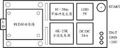
图4是激光发射模块所在的电路板的一种布局的示意图;Fig. 4 is a schematic diagram of a layout of a circuit board where the laser emitting module is located;
图5是激光接收模块所在的电路板的一种布局的示意图;Fig. 5 is a schematic diagram of a layout of a circuit board where the laser receiving module is located;
图6是图1中的ARM控制器的一种具体结构的示意图。FIG. 6 is a schematic diagram of a specific structure of the ARM controller in FIG. 1 .
具体实施方式Detailed ways
为使本发明实施例的目的、技术方案和优点更加清楚,下面将结合本发明实施例中的附图,对本发明实施例中的技术方案进行清楚、完整地描述,显然,所描述的实施例是本发明一部分实施例,而不是全部的实施例。基于本发明中的实施例,本领域普通技术人员在没有做出创造性劳动前提下所获得的所有其他实施例,都属于本发明保护的范围。In order to make the purpose, technical solutions and advantages of the embodiments of the present invention clearer, the technical solutions in the embodiments of the present invention will be clearly and completely described below in conjunction with the drawings in the embodiments of the present invention. Obviously, the described embodiments It is a part of embodiments of the present invention, but not all embodiments. Based on the embodiments of the present invention, all other embodiments obtained by persons of ordinary skill in the art without making creative efforts belong to the protection scope of the present invention.
图1是本发明提供的激光雷达监测系统的一个实施例的示意图,如图1所示,本实施例中的激光雷达监测系统包括激光发射模块1、激光接收模块2、信号处理及控制模块3、旋转扫描机构4。Fig. 1 is a schematic diagram of an embodiment of the laser radar monitoring system provided by the present invention. As shown in Fig. 1, the laser radar monitoring system in this embodiment includes a laser emitting module 1, a
其中,激光发射模块1用于发射脉冲激光,并将反映脉冲激光发射时间的信号发送至信号处理及控制模块3。本实施例中的激光雷达通过根据脉冲激光的发射时间和接收时间的时延完成被监测区域中的目标的测距,并通过对被监测区域的扫描获取整个被监测区域的目标信息。Wherein, the laser emitting module 1 is used for emitting pulsed laser, and sends a signal reflecting the time of pulsed laser emission to the signal processing and control module 3 . The laser radar in this embodiment completes the distance measurement of the target in the monitored area according to the time delay between the emission time and reception time of the pulsed laser, and obtains the target information of the entire monitored area by scanning the monitored area.
激光接收模块2用于接收从被监测区域反射回的脉冲激光,并将反映接收脉冲激光的时间的信号发送至信号处理及控制模块3。The
旋转扫描机构4用于通过旋转,利用激光发射模块1发射的脉冲激光扫描被监测区域中的各个位置,并将从被监测区域各个位置反射回的脉冲激光依次收集到激光接收模块2中。The rotating scanning mechanism 4 is used to scan various positions in the monitored area with the pulsed laser emitted by the laser emitting module 1 through rotation, and collect the pulsed lasers reflected from each position in the monitored area into the
信号处理及控制模块3与激光发射模块1和激光接收模块2相连,对激光发射模块1和激光接收模块2进行控制,并从其接收信号。信号处理及控制模块3根据从激光发射模块1接收到的反映脉冲激光发射时间的信号、以及从激光接收模块2接收到的反映接收脉冲激光的时间的信号,得到脉冲激光的发射时间与同一脉冲激光从被监测区域反射并被接收的接收时间之间的时间差,由该时间差可以得到被监测区域的目标信息。上述过程都是信号处理及控制模块3根据激光测距的原理,探测被监测区域的信息。接着信号处理及控制模块3将获得的被监测区域的目标距离信息,并同时与旋转扫描机构4中的马达上传的霍尔传感器的角度信息匹配,得到检测目标的距离角度信息组。该信息在固定周期内集合为帧数据传递给报警处理模块,通过背景的滤除与人员定位与跟踪方法确定告警。这里背景技术包含即使没有告警情况出现,扫描被检测区域也会得到的目标信息,由于这些信息并不是告警所关心的信息,而且其也常常反映了除了入侵者之外的其他不动目标的信息,所以可以称为背景信息。The signal processing and control module 3 is connected with the laser emitting module 1 and the
信号处理及控制模块3根据报警处理模块中进行背景滤除、人员检测过程后判定是否告警。这里可以根据告警点的数量和/或位置判定是否告警。The signal processing and control module 3 determines whether to give an alarm according to background filtering and personnel detection in the alarm processing module. Here, it may be determined whether to give an alarm according to the number and/or positions of the alarm points.
激光雷达具有工作稳定、检测概率高,漏检率低的优点。Lidar has the advantages of stable operation, high detection probability, and low missed detection rate.
图2示出了上述激光发射模块1的一种具体结构,如图2所示,该激光发射模块1包括激光二极管(LD)11、激光脉冲二极管(PLD)驱动电路12、窄脉冲发生器13和方波发生器14。激光二极管11作为光源,由PLD驱动电路12驱动。窄脉冲发生器13和方波发生器14均与PLD驱动电路12相连,为PLD驱动电路提供脉冲信号,以使PLD驱动电路12根据该脉冲信号向激光二极管11输出对应的脉冲驱动电压。其中,窄脉冲发生器13的脉冲频率优选在1KHz-30KHz之间可调,正脉宽优选在10ns-10μs之间可调,其输出的脉冲信号高电平优选为5V,低电平优选为0V。上升沿的上升时间优选为10ns以内,这样可以保证最终输出的激光脉冲的波形比较理想,避免过多的噪声引起的计时芯片误计时。Fig. 2 has shown a kind of specific structure of above-mentioned laser emission module 1, as shown in Fig. 2, this laser emission module 1 comprises laser diode (LD) 11, laser pulse diode (PLD) driving
需要说明的是,在上述激光发射模块1中还可以设置尖峰抑制电路,以对电路中的幅值不均现象进行调整。It should be noted that a spike suppression circuit may also be provided in the above-mentioned laser emitting module 1 to adjust the amplitude unevenness in the circuit.
图3示出了上述激光接收模块2的一种具体结构。如图3所示,该激光接收模块2包括雪崩接收管(APD)21、前置放大器22、电压放大器23、整形调理电路24和DC/DC逆变器25。其中,雪崩接收管21用于接收从被检测区域反射回的脉冲激光,并将其转换成相对应的电脉冲信号。前置放大器22接收雪崩接收管21输出的电脉冲信号,并对其进行放大。电压放大器23还用于对从前置放大器22输出的信号进行放大,整形调理电路24将对输入其中的模拟电信号转换成上升沿陡峭的数字信号,便于信号处理及控制模块3对其进行处理,提高计时的精度。DC/DC逆变器25给雪崩接收管21供电,为其提供反向击穿电压。FIG. 3 shows a specific structure of the above-mentioned
需要说明的是,本领域技术人员应该可以理解,上述激光接收模块2中的雪崩接收管21还可以替换为其他类型的光电检测器。It should be noted that those skilled in the art should understand that the
上述激光发射模块1可以通过START管脚信号的上升沿向信号处理及控制模块3告知激光发射模块1已经发射出一个脉冲激光,而激光接收模块2可以通过STOP管脚信号的上升沿向信号信号处理及控制模块3告知激光接收模块2已经接收到从被监测区域反射回的一个脉冲激光;这样,信号处理及控制模块3可以通过接收上述START管脚信号的上升沿的时间以及接收上述STOP管脚信号的上升沿的时间,分别确定同一脉冲激光发射的时间和从被监测区域反射回并被接收的时间。The above-mentioned laser emitting module 1 can notify the signal processing and control module 3 that the laser emitting module 1 has emitted a pulsed laser through the rising edge of the START pin signal, and the
以下详细说明信号处理及控制模块的内部结构,请参见图1。信号处理及控制模块3可以包括时间检测(TDC)模块31、ARM控制器32和接口模块33。The following details the internal structure of the signal processing and control module, please refer to Figure 1. The signal processing and control module 3 may include a time detection (TDC)
其中,时间检测模块31用于在接收到ARM控制器32的触发信号后,根据接收到的反映脉冲激光发射时间的信号和反映接收脉冲激光的时间的信号,得到脉冲激光的发射时间和接收时间的时间差,并在检测完成后,向ARM控制器32发送检测到的时间差。Wherein, the
ARM控制器32用于向时间检测模块31发送触发信号,并接收时间检测模块31发送的由其检测到的时间差,并由该时间差得到被监测区域的目标信息,并将其与预先建立的反映被检测区域的背景信息的地图数据进行差分,得到告警点的信息,由告警点的位置和/或数量判定是否告警。
上述接口模块33用于建立信号处理和控制装置32与上位机之间的联系,由此可以完成同一台上位机监控多个激光雷达。在图1中特别地,接口模块33中包括USB接口、以太网口、RS-232接口。The above-mentioned
为了满足ARM控制器32和时间检测模块31之间高速数据传输的要求,ARM控制器32和时间检测模块31之间传送数据的接口优选采用SPI口,例如在ARM控制器32和时间检测模块31之间建立10条信号线,其中4条为采用SPI进行通信,用于传输激光雷达测距结果,而另外6条用于传输计时信号和控制信号。计时信号包括计时开始信号和计时停止信号。控制信号可以包括通道使能信号,该使能信号用于在不用通道时,将该通道关闭,从而最大程度地降低空闲通道的噪声干扰对计时的影响。In order to meet the requirements of high-speed data transmission between the
在实际中,激光发射模块1和激光接收模块2所在的电路板的布局可以灵活设置。例如,图4示出了激光发射模块1所在的电路板的布局,在图4中,电路板上还设置了LDO和DC/DC电源,二者分别提供5V的电压和大于24V的电压。图5示出了激光接收模块2所在的电路板的布局,在图5中,电路板上除了激光接收模块2自身的组成单元外,还集成了信号处理及控制模块中的时间检测模块,同理,图5中的电路板中也设置了该板上的功能单元所需要的电源,例如提供5V电压和3.3V电压的LDO、以及提供9-24V电压的DC/DC电源。在图4和图5中的电路板的边缘处还设置了图1中所需的管脚,另外还设置了方便固定的固定孔。In practice, the layout of the circuit board where the laser emitting module 1 and the
以下详细说明ARM控制器32如何实现告警点的识别。How the
图6示出了ARM控制器32的具体结构。如图6所示,该ARM控制器可以包括信号检测子模块601,该信号检测子模块601具体用于将被检测区域的目标信息与建立的地图数据进行差分得到告警点。信号检测子模块601可以包括:数据预处理单元6011、背景去除单元6012、分割单元6013、特征提取单元6014和数据融合单元6015。FIG. 6 shows the specific structure of the
其中,数据预处理单元6011用于对被检测区域的目标信息进行滤波,以达到初步干扰点滤除。由于通过激光雷达在激光测距的过程中,所得的数据中会有一些孤立的点,他们与相邻的点的距离都比较大,这些孤立的点属于干扰点,在对数据进行后续处理之前需要将其滤除。本实施例中,数据预处理单元6011优选采用中值滤波的方法对干扰点进行滤除。中值滤波方法是基于排序统计理论的一种能有效抑制噪声的非线性信号处理技术,其基本原理是把数字图像或数字序列中一点的值用该点的一个邻域中的各点值的中值代替,从而可以消除孤立的噪声点。Among them, the
背景去除单元6012用于将经过干扰点滤除的目标信息预先建立的地图数据进行差分得到差分后的目标信息。The
分割单元6013用于初步分割属于不同物体的数据点。分割单元6013根据判定阈值初步划分属于不同物体的数据点。本实施例中优选地,分割单元6013根据障碍物距离激光接收模块2的距离选择可变的判定阈值,在设定上述判定阈值的过程中综合考虑如下因素:障碍物距离激光接收模块2越近,则数据点越密;扫描角度与环境的走向的夹角越小,则数据点越密。例如可以基于线性阈值法进行分割。
特征提取单元6014用于根据上述分割单元6013分割后的每个物体的不同数据点信息,提取每个物体的形状和/或运动特征信息。这些提取的特征信息对后续进行目标分类和跟踪起到至关重要的作用。上述物体的形状信息可以为:物体的质心、外形、以及物体轮廓的线性度、曲率或椭圆率中的任意一个或者任意组合。上述物体的运动特征信息可以为:物体当前位置的笛卡尔坐标、运动速度、角速度或加速度中的任意一个或任意组合。因为大多数物体都可以由较为规则的直线段组合而成,而且民用防入侵领域中需要探测的主要是入侵人员,入侵人员往往表现为直立的线段特征,所以在特征信息提取时,线性特征提取将是主要采用的手段。线性特征提取的过程可以基于线性回归、霍夫变换、增量算法、最大期望值算法等方法完成。The
数据融合单元6015用于综合上述特征提取单元6014提取后的特征信息,将特征信息满足预定规则的被分割的相邻数据点所属于的不同物体重新划分为同一物体,同时在时间上实现相同物体的匹配。The
在经过上述分段单元6014分段后,可能会将本该属于同一物体的数据点划分为属于两个不同的物体,即将一个完整的物体划分成多个段。单独地对每个段进行后续的特征分析以识别目标是没有意义的。另外,在将物体分成多个部分进行分析时,可能会造成属于不同物体的不同段的特征分析结果是相同的,这就造成无法对被检测区域的目标类型进行区分。另外,仅仅根据目标的形状特征有时还不能够准确地判断目标的类型,这是需要结合目标的运动特征,所以还需要综合考虑前后一定数量的帧扫描数据。After being segmented by the
基于上面的考虑,需要数据融合单元6015将一帧数据中的多个数据点进行空间融合,同时将多帧数据进行时间融合。例如,人的两条腿在同一帧数据中的特征是相类似的,但很可能被划分为两个物体,但是如果在一定阈值范围内发现了类似特征,则这两个段内分别是同一个人的两条腿中的一条腿的可能性就比较大了,此时,需要将上述连续的两个段融合到一起。同时,人腿与一根圆棒在段内的数据特征可能是一致的,通过比较多帧中的目标运动特性将可以有效的得到人腿与圆木的区别,以便于多帧中相同目标的匹配,实现后续跟踪等功能。Based on the above considerations, the
地图数据在使用一段时间后,可能会由于被检测区域的实际背景发生变化,造成利用原有的地图数据去识别目标的结果将发生错误。为了克服上述问题,优选地,在ARM控制器32中还设置一个地图重建模块602。该地图重建模块602用于在发生重建地图触发事件时,将信号检测子模块601中的数据预处理单元6011得到的经过干扰点滤除的目标信息做背景环境拟合运算,得到重建后的地图数据。After the map data is used for a period of time, the actual background of the detected area may change, resulting in an error in the result of using the original map data to identify the target. In order to overcome the above problems, preferably, a
上述重建地图数据触发事件从多种角度去考虑设置,至少可以从检测结果和背景发生变化的经验时间上去考虑。例如,从检测结果的角度看,当系统在外力下位置发生变动或被检测区域的背景发生变化后,继续利用原有的地图数据对经过目标信息进行差分,所得的结果中将出现数量、持续时间严重异常的告警点,另外这些告警点的在一帧数据中的位置分布也将比正常出现入侵者时的分布更分散且靠近背景点,所以系统可以维护一个检测异常标识位,当系统检测后的告警点的数量和/或位置分布超出正常告警点的范围,则将该检测异常标识位修改为“异常”,此时地图重建模块602将启动地图数据重建的功能,当重建完成后,再将上述标志位修改为“正常”。从背景发生变化的经验时间去考虑,使用者可以通过统计激光雷达所监测区域的背景变化的经验时间,设定一个定时器,并由地图重建模块602检测该定时器的时间是否到达上述的经验时间,如果到达,则启动地图数据重建的功能,当重建完成后,再将上述定时器重置,以重新计时。The above-mentioned reconstruction map data trigger event can be set from various perspectives, at least from the experience time of detection results and background changes. For example, from the perspective of detection results, when the position of the system changes under external force or the background of the detected area changes, the original map data will continue to be used to differentiate the passing target information, and the results obtained will appear in the number, continuous Alarm points with serious time anomalies. In addition, the position distribution of these alarm points in a frame of data will be more scattered and close to the background points than the normal distribution of intruders, so the system can maintain a detection abnormality flag. When the system detects After the number and/or position distribution of the warning points exceeds the scope of the normal warning points, then the detection abnormal flag is modified to "abnormal", and now the
在进行上述数据融合的过程中,数据点所对应的实际目标的角度信息是很重要的,为了提高该角度信息的精确性,优选地,在上述激光雷达监测系统中还设置一个光电开关5,该光电开关5在旋转扫描机构4旋转一圈时,产生一个周脉冲。另外,在旋转扫描机构4中的马达中安装霍尔传感器,用于输出旋转扫描机构的旋转角度,这样可以对雷达的角度信息以修正。In the process of carrying out the above-mentioned data fusion, the angle information of the actual target corresponding to the data points is very important. In order to improve the accuracy of the angle information, preferably, a photoelectric switch 5 is also set in the above-mentioned laser radar monitoring system, The photoelectric switch 5 generates a cycle pulse when the rotary scanning mechanism 4 rotates once. In addition, a Hall sensor is installed in the motor of the rotary scanning mechanism 4 to output the rotation angle of the rotary scanning mechanism, so that the angle information of the radar can be corrected.
以上所述仅是本发明的优选实施方式,应当指出,对于本技术领域的普通技术人员来说,在不脱离本发明原理的前提下,还可以做出若干改进和润饰,这些改进和润饰也应视为本发明的保护范围。The above is only a preferred embodiment of the present invention, it should be pointed out that, for those of ordinary skill in the art, without departing from the principle of the present invention, some improvements and modifications can also be made, and these improvements and modifications can also be made. It should be regarded as the protection scope of the present invention.
Claims (8)
Translated fromChinesePriority Applications (1)
| Application Number | Priority Date | Filing Date | Title |
|---|---|---|---|
| CN201010606326.0ACN102540193B (en) | 2010-12-24 | 2010-12-24 | Laser radar monitoring system |
Applications Claiming Priority (1)
| Application Number | Priority Date | Filing Date | Title |
|---|---|---|---|
| CN201010606326.0ACN102540193B (en) | 2010-12-24 | 2010-12-24 | Laser radar monitoring system |
Publications (2)
| Publication Number | Publication Date |
|---|---|
| CN102540193A CN102540193A (en) | 2012-07-04 |
| CN102540193Btrue CN102540193B (en) | 2014-04-30 |
Family
ID=46347519
Family Applications (1)
| Application Number | Title | Priority Date | Filing Date |
|---|---|---|---|
| CN201010606326.0AActiveCN102540193B (en) | 2010-12-24 | 2010-12-24 | Laser radar monitoring system |
Country Status (1)
| Country | Link |
|---|---|
| CN (1) | CN102540193B (en) |
Families Citing this family (29)
| Publication number | Priority date | Publication date | Assignee | Title |
|---|---|---|---|---|
| TWI574026B (en)* | 2014-11-21 | 2017-03-11 | 專家科技有限公司 | Ranging method, ranging device, location device and location method |
| TWI565960B (en)* | 2014-11-21 | 2017-01-11 | 專家科技有限公司 | Ranging method, ranging device, location device and location method |
| JP6418961B2 (en)* | 2015-01-28 | 2018-11-07 | シャープ株式会社 | Obstacle detection device, moving object, obstacle detection method, and obstacle detection program |
| US9625582B2 (en) | 2015-03-25 | 2017-04-18 | Google Inc. | Vehicle with multiple light detection and ranging devices (LIDARs) |
| CN106324618B (en)* | 2015-06-17 | 2019-03-15 | 高田汽车电子(上海)有限公司 | Realize the method based on laser radar detection lane line system |
| CN105277944B (en)* | 2015-09-23 | 2018-03-27 | 上海物景智能科技有限公司 | A laser ranging radar and its power supply control method |
| JP6852085B2 (en)* | 2015-11-30 | 2021-03-31 | ルミナー テクノロジーズ インコーポレイテッド | Photodetection and ranging systems with distributed lasers and multiple sensor heads, and pulsed lasers for photodetection and ranging systems |
| CN105912027A (en)* | 2016-06-30 | 2016-08-31 | 西安交通大学 | Obstacle avoiding device and obstacle avoiding method of unmanned aerial vehicle |
| CN106289278B (en)* | 2016-08-08 | 2019-03-12 | 成都希德电子信息技术有限公司 | Navigation system and method for dangerous road condition advisory |
| CN108072877A (en)* | 2016-11-10 | 2018-05-25 | 光宝电子(广州)有限公司 | Optical devices |
| CN106970391B (en)* | 2017-03-31 | 2019-10-11 | 成都微光云科技有限公司 | A kind of UAV terrain detection system based on laser ranging |
| US10416679B2 (en)* | 2017-06-27 | 2019-09-17 | GM Global Technology Operations LLC | Method and apparatus for object surface estimation using reflections delay spread |
| DE102017217844A1 (en)* | 2017-10-06 | 2019-04-11 | Robert Bosch Gmbh | Method and a machine learning system for classifying objects |
| KR102030458B1 (en)* | 2017-10-25 | 2019-11-08 | 현대오트론 주식회사 | LIDAR signal processing apparatus and method |
| CN108153308A (en)* | 2017-12-21 | 2018-06-12 | 李华 | For the composite vision Laser navigation system and its control method of robotic vehicle automatic Pilot |
| CN110275173B (en)* | 2018-03-13 | 2024-03-22 | 深圳越登智能技术有限公司 | Laser ranging system |
| EP3775983A1 (en)* | 2018-04-09 | 2021-02-17 | Innoviz Technologies Ltd. | Lidar systems and methods with internal light calibration |
| CN108426562A (en)* | 2018-05-14 | 2018-08-21 | 北京雷图科技有限公司 | A kind of laser tunnel cross-section detector |
| CN108872967A (en)* | 2018-05-15 | 2018-11-23 | 天津杰泰高科传感技术有限公司 | Laser radar narrow-pulse generation circuit and method |
| CN108627849B (en)* | 2018-07-25 | 2022-02-15 | 南京富锐光电科技有限公司 | Range finding laser radar system for high-speed camera calibration |
| CN112346077A (en)* | 2019-08-08 | 2021-02-09 | 杭州海康威视系统技术有限公司 | Ship superelevation detection method and device, electronic equipment and storage medium |
| DE102019122566A1 (en)* | 2019-08-22 | 2021-02-25 | Valeo Schalter Und Sensoren Gmbh | Method for operating an optoelectronic detection device and optoelectronic detection device |
| CN113126640B (en)* | 2019-12-31 | 2022-06-28 | 北京三快在线科技有限公司 | Obstacle detection method and device for unmanned aerial vehicle, unmanned aerial vehicle and storage medium |
| CN112021998B (en)* | 2020-07-20 | 2023-08-29 | 科沃斯机器人股份有限公司 | Data processing method, measurement system, autonomous mobile device and cleaning robot |
| CN112098971B (en)* | 2020-09-16 | 2022-07-15 | 上海商汤临港智能科技有限公司 | Method and device for configuring radar, electronic equipment and storage medium |
| CN112731430B (en)* | 2020-12-15 | 2024-06-11 | 武汉万集光电技术有限公司 | High-altitude parabolic detection method and system based on laser radar |
| CN113325438A (en)* | 2021-05-12 | 2021-08-31 | 天地(常州)自动化股份有限公司 | System and method for collecting and generating underground environment information |
| CN113237476A (en)* | 2021-05-19 | 2021-08-10 | 湖北科技学院 | Construction site safety early warning system and method |
| CN115060476B (en)* | 2022-01-12 | 2024-04-26 | 北京恒润安科技有限公司 | Gate fault investigation method for accurate laser ranging |
Citations (4)
| Publication number | Priority date | Publication date | Assignee | Title |
|---|---|---|---|---|
| CN101241189A (en)* | 2008-03-07 | 2008-08-13 | 邵泽德 | Two-dimensional scanning laser collision avoidance radar system |
| CN101267548A (en)* | 2008-02-04 | 2008-09-17 | 长春理工大学 | Space laser audio and video transmission system |
| CN101393072A (en)* | 2008-11-10 | 2009-03-25 | 中国兵器工业第二〇五研究所 | Power supply drive device for pulse semiconductor laser test equipment |
| CN202025084U (en)* | 2010-12-24 | 2011-11-02 | 无锡物联网产业研究院 | Laser radar monitoring system |
- 2010
- 2010-12-24CNCN201010606326.0Apatent/CN102540193B/enactiveActive
Patent Citations (4)
| Publication number | Priority date | Publication date | Assignee | Title |
|---|---|---|---|---|
| CN101267548A (en)* | 2008-02-04 | 2008-09-17 | 长春理工大学 | Space laser audio and video transmission system |
| CN101241189A (en)* | 2008-03-07 | 2008-08-13 | 邵泽德 | Two-dimensional scanning laser collision avoidance radar system |
| CN101393072A (en)* | 2008-11-10 | 2009-03-25 | 中国兵器工业第二〇五研究所 | Power supply drive device for pulse semiconductor laser test equipment |
| CN202025084U (en)* | 2010-12-24 | 2011-11-02 | 无锡物联网产业研究院 | Laser radar monitoring system |
Non-Patent Citations (4)
| Title |
|---|
| 冯聪慧.机载激光雷达系统数据处理方法的研究.《中国优秀硕士学位论文全文数据库》.2008,(第6期),第6-14页. |
| 机载激光雷达系统数据处理方法的研究;冯聪慧;《中国优秀硕士学位论文全文数据库》;20080630(第6期);第6-14页* |
| 李玉江等.霍尔传感器用于角度测量的一种方法.《电子机械工程》.2001,(第4期),25-26. |
| 霍尔传感器用于角度测量的一种方法;李玉江等;《电子机械工程》;20010831(第4期);25-26* |
Also Published As
| Publication number | Publication date |
|---|---|
| CN102540193A (en) | 2012-07-04 |
Similar Documents
| Publication | Publication Date | Title |
|---|---|---|
| CN102540193B (en) | Laser radar monitoring system | |
| CN202025084U (en) | Laser radar monitoring system | |
| US11971507B2 (en) | Systems and methods for mitigating optical crosstalk in a light ranging and detection system | |
| US11402469B2 (en) | Radar target detection system and method | |
| CN103576159B (en) | A kind of runway road surface checking device based on laser scanner technique and method | |
| US20180188357A1 (en) | HIGH RESOLUTION LiDAR USING HIGH FREQUENCY PULSE FIRING | |
| CN107238842B (en) | An area array target searching scanning imaging device and method | |
| CN108279407A (en) | A kind of laser radar echo processing system and method | |
| MX2014003119A (en) | Improved laser rangefinder sensor. | |
| CA2839194A1 (en) | System and method for traffic side detection and characterization | |
| CN104570834B (en) | A kind of laser instrument and wrong detection and recovery device, method | |
| IL264733B1 (en) | Method and system for determining as a target and tracking an intruder using a laser-based detection and range measurement device | |
| JP2014059834A (en) | Laser scan sensor | |
| CN210542119U (en) | Intelligent wheelchair with obstacle avoidance and face recognition functions | |
| CN104199043B (en) | Traffic sign detection method | |
| CN102661746B (en) | Sensor main mounting boxes and passive optical sensor | |
| CN209356671U (en) | A kind of laser radar background dark noise response cancellation element | |
| CN107202993A (en) | Cascaded acousto-optic wide-field laser 3D imaging system based on full waveform sampling | |
| CN109568093A (en) | A kind of walking safety integrated management system and method | |
| CN106997050A (en) | A kind of scan-type visibility laser radar | |
| EP3974861A3 (en) | Ground based aircraft laser collision detection system | |
| KR20140034364A (en) | Human sensing security system using impulse uwb (ultra wide band) radar | |
| JP2017215642A (en) | Monitoring system | |
| CN111213069B (en) | Obstacle avoidance device and method based on coherent light | |
| JP2012251900A (en) | Leftover object detecting method and device |
Legal Events
| Date | Code | Title | Description |
|---|---|---|---|
| C06 | Publication | ||
| PB01 | Publication | ||
| C10 | Entry into substantive examination | ||
| SE01 | Entry into force of request for substantive examination | ||
| C14 | Grant of patent or utility model | ||
| GR01 | Patent grant | ||
| PP01 | Preservation of patent right | Effective date of registration:20201119 Granted publication date:20140430 | |
| PP01 | Preservation of patent right | ||
| PD01 | Discharge of preservation of patent | ||
| PD01 | Discharge of preservation of patent | Date of cancellation:20210112 Granted publication date:20140430 | |
| PP01 | Preservation of patent right | Effective date of registration:20210112 Granted publication date:20140430 | |
| PP01 | Preservation of patent right | ||
| PD01 | Discharge of preservation of patent | Date of cancellation:20230509 Granted publication date:20140430 | |
| PD01 | Discharge of preservation of patent | ||
| CP03 | Change of name, title or address | Address after:214135 Gemini A, No. 18 Zhenze Road, New District, Wuxi City, Jiangsu Province, Wuxi National Software Park Patentee after:Wuxi Research Institute of Internet of Things Country or region after:China Patentee after:SENSINGNET GROUP Co.,Ltd. Address before:214135 Gemini A, No. 18 Zhenze Road, New District, Wuxi City, Jiangsu Province, Wuxi National Software Park Patentee before:Wuxi Research Institute of Internet of Things Country or region before:China Patentee before:SENSING NET GROUP (WUXI) Co.,Ltd. | |
| CP03 | Change of name, title or address | ||
| TR01 | Transfer of patent right | Effective date of registration:20241219 Address after:214000 floor 7, block a, Xidong chuangrong building, No. 78, Danshan Road, anzhen street, Xishan District, Wuxi City, Jiangsu Province Patentee after:Perception Qiyin Technology (Wuxi) Co.,Ltd. Country or region after:China Address before:214135 Gemini A, No. 18 Zhenze Road, New District, Wuxi City, Jiangsu Province, Wuxi National Software Park Patentee before:Wuxi Research Institute of Internet of Things Country or region before:China Patentee before:SENSINGNET GROUP Co.,Ltd. | |
| TR01 | Transfer of patent right |