CN102538763A - Method for measuring three-dimensional terrain in river model test - Google Patents
Method for measuring three-dimensional terrain in river model testDownload PDFInfo
- Publication number
- CN102538763A CN102538763ACN2012100331880ACN201210033188ACN102538763ACN 102538763 ACN102538763 ACN 102538763ACN 2012100331880 ACN2012100331880 ACN 2012100331880ACN 201210033188 ACN201210033188 ACN 201210033188ACN 102538763 ACN102538763 ACN 102538763A
- Authority
- CN
- China
- Prior art keywords
- camera
- bed surface
- point
- laser
- spike
- Prior art date
- Legal status (The legal status is an assumption and is not a legal conclusion. Google has not performed a legal analysis and makes no representation as to the accuracy of the status listed.)
- Granted
Links
Images

Classifications
- Y—GENERAL TAGGING OF NEW TECHNOLOGICAL DEVELOPMENTS; GENERAL TAGGING OF CROSS-SECTIONAL TECHNOLOGIES SPANNING OVER SEVERAL SECTIONS OF THE IPC; TECHNICAL SUBJECTS COVERED BY FORMER USPC CROSS-REFERENCE ART COLLECTIONS [XRACs] AND DIGESTS
- Y02—TECHNOLOGIES OR APPLICATIONS FOR MITIGATION OR ADAPTATION AGAINST CLIMATE CHANGE
- Y02A—TECHNOLOGIES FOR ADAPTATION TO CLIMATE CHANGE
- Y02A20/00—Water conservation; Efficient water supply; Efficient water use
- Y02A20/40—Protecting water resources
- Y02A20/402—River restoration
- Y—GENERAL TAGGING OF NEW TECHNOLOGICAL DEVELOPMENTS; GENERAL TAGGING OF CROSS-SECTIONAL TECHNOLOGIES SPANNING OVER SEVERAL SECTIONS OF THE IPC; TECHNICAL SUBJECTS COVERED BY FORMER USPC CROSS-REFERENCE ART COLLECTIONS [XRACs] AND DIGESTS
- Y02—TECHNOLOGIES OR APPLICATIONS FOR MITIGATION OR ADAPTATION AGAINST CLIMATE CHANGE
- Y02A—TECHNOLOGIES FOR ADAPTATION TO CLIMATE CHANGE
- Y02A90/00—Technologies having an indirect contribution to adaptation to climate change
- Y02A90/30—Assessment of water resources
Landscapes
- Length Measuring Devices By Optical Means (AREA)
- Image Processing (AREA)
Abstract
Description
Translated fromChinese技术领域technical field
本发明属于水利量测技术领域,特别是河工模型试验的复杂三维地形的动态量测。The invention belongs to the technical field of water conservancy measurement, in particular to the dynamic measurement of complex three-dimensional topography in river engineering model tests.
背景技术Background technique
在水利工程的河工模型试验中,河床地形将随着河道的冲淤过程而变化,如河岸坍塌、边滩消长等。实时监测河道的变形是河工模型试验的关键技术。In the river engineering model test of hydraulic engineering, the topography of the river bed will change with the erosion and deposition process of the river, such as the collapse of the river bank and the ebb and flow of the side beach. Real-time monitoring of channel deformation is a key technology for river engineering model tests.
现有的河工模型地形测量技术多为单点测量,常用的方法一般有①钢尺测量法、②测针测量法、③光电式地形仪、④电阻式地形仪、⑤超声波地形仪等,并且前4个测量方法为接触式,操作过程中会对床面造成破坏。另外,这些传统的测量方法费工费时,以常用的④或⑤为例,首先要在模型河道上布置测量横断面,在两岸安装轨道并在轨道上架设测桥、安装测车,采用安装在测车上的超声地形仪、电阻测淤仪等在测桥上自动行走,测量断面上各点的河床高度,继而通过相关软件重构河道的三维地形。北京尚水信息技术股份有限公司的产品“超声地形自动测量分析系统”具有代表性。但是此类单点测量方法工作量过大、数据量过少、测量效率过低,三维重构的精度不高。Most of the existing topographic measurement technologies for river engineering models are single-point measurement. The commonly used methods generally include ① steel ruler measurement method, ② stylus measurement method, ③ photoelectric topography instrument, ④ resistive topography instrument, ⑤ ultrasonic topography instrument, etc., and The first four measurement methods are contact methods, which will cause damage to the bed surface during operation. In addition, these traditional measurement methods are labor-intensive and time-consuming. Take the commonly used method ④ or ⑤ as an example. The ultrasonic topography instrument and resistance silt measuring instrument on the measuring vehicle automatically walk on the measuring bridge to measure the height of the riverbed at each point on the cross-section, and then reconstruct the three-dimensional topography of the river channel through relevant software. The product "Ultrasonic Terrain Automatic Measurement and Analysis System" of Beijing Shangshui Information Technology Co., Ltd. is representative. However, this kind of single-point measurement method has too much workload, too little data, low measurement efficiency, and low accuracy of 3D reconstruction.
近年来,作为非接触式量测技术的激光扫描仪在河工模型地形量测领域内得到了一定的发展,如瑞士的徕卡HDS3000三维激光扫描仪和奥地利的Riegl LPM-2K三维激光扫描仪,可自动进行三维地形的单点连续扫描,并将扫描的散点数据重构生成三维地形。其性能指标:扫描距离2-150米;扫描精度2-6毫米;扫描角度270×360度;扫描速度1000点/秒。该仪器测量精度高,扫描的速度快,不需要轨道、测桥、测车等辅助设施,很适合于固定构造物的一次性精确扫描,如城市勘察、文物建筑测绘等。但在用于河工模型试验中的动态河床测量时,每次移动都需要重新标定仪器的三维坐标和水平方向角;由于一次地形的测量工作量很大,难以实现实时测量;当仪器视线与被测地形的夹角较小时,测量精度较差,甚至会因为地形起伏的遮挡而产生错误;且该仪器的价格昂贵。In recent years, the laser scanner as a non-contact measurement technology has been developed in the field of topographic measurement of river engineering models, such as the Swiss Leica HDS3000 3D laser scanner and the Austrian Riegl LPM-2K 3D laser scanner, which can Automatically perform single-point continuous scanning of 3D terrain, and reconstruct the scanned scatter point data to generate 3D terrain. Its performance indicators: scanning distance 2-150 meters; scanning accuracy 2-6 mm; scanning angle 270 × 360 degrees; scanning speed 1000 points/second. The instrument has high measurement accuracy and fast scanning speed. It does not need auxiliary facilities such as tracks, bridges, and vehicles. It is very suitable for one-time accurate scanning of fixed structures, such as urban surveys, cultural relics and architectural surveys. However, when it is used for dynamic river bed measurement in river engineering model tests, the three-dimensional coordinates and horizontal direction angle of the instrument need to be recalibrated every time it is moved; due to the heavy workload of a terrain measurement, it is difficult to achieve real-time measurement; when the line of sight of the instrument is in line with the target When the included angle of terrain measurement is small, the measurement accuracy is poor, and even errors may occur due to the occlusion of terrain undulations; and the instrument is expensive.
近几十年来,双目立体视觉技术在工业、农业、军事、考古、交通等相关领域得到了极大的应用与发展,如机器人快速移动避障碍、植物叶片三维立体重建、月球、火星表面地形探测等。双目立体视觉是通过对同一目标的两幅图像提取、识别、匹配,重建三维环境信息的过程。主要包括:图像捕获、摄像机标定、图像预处理和特征提取、立体匹配以及所测物体表面形状三维重建。该技术在河工模型地形量测方面也得到了初步的尝试,如河海大学毛野等人运用该技术研究河道采砂对长江镇江段河床演变的影响等,但是类似的尝试在河工模型床面上特征点的示踪、匹配、提取及三维空间坐标计算等问题上并没有得到很好的解决。In recent decades, binocular stereo vision technology has been greatly applied and developed in related fields such as industry, agriculture, military, archaeology, transportation, etc. probing etc. Binocular stereo vision is the process of reconstructing three-dimensional environment information by extracting, identifying, and matching two images of the same target. It mainly includes: image capture, camera calibration, image preprocessing and feature extraction, stereo matching and three-dimensional reconstruction of the surface shape of the measured object. This technology has also been initially tried in the topographic measurement of river engineering models. Problems such as tracking, matching, extraction of feature points and calculation of three-dimensional space coordinates have not been well resolved.
发明内容Contents of the invention
本发明提出了一种河工模型试验的三维地形动态测量方法,用以实时量测河工模型试验中床面的三维形态。本方法基于双目立体视觉原理,利用图像摄取技术、激光矩阵光源示踪技术和三维地形重构技术来实时量测河工模型试验中床面的三维形态。具有经济实用、安全可靠、质量高的优点。The invention proposes a three-dimensional terrain dynamic measurement method for a river engineering model test, which is used for real-time measurement of the three-dimensional shape of the bed surface in the river engineering model test. Based on the principle of binocular stereo vision, this method uses image capture technology, laser matrix light source tracing technology and three-dimensional terrain reconstruction technology to measure the three-dimensional shape of the bed surface in the river engineering model test in real time. The utility model has the advantages of being economical, practical, safe and reliable, and high in quality.
本发明提出的一种河工模型试验三维地形的测量方法,其特征在于,采用两台参数相同的数码相机,一台连续激光矩形点阵示踪光斑发射装置,以及分别与两台数码相机相连的一台计算机;所述连续激光矩形点阵示踪光斑发射装置由连续激光器和微调光栅所组成;该微调光栅在河工模型床面上投射出不同间距及大小的矩形点阵示踪光斑,其中矩形点阵示踪光斑中心点为定位点O;A method for measuring three-dimensional topography of a river engineering model test proposed by the present invention is characterized in that two digital cameras with the same parameters, a continuous laser rectangular lattice tracer spot emitting device, and two digital cameras respectively connected to each other are used. A computer; the continuous laser rectangular lattice tracer spot emitting device is composed of a continuous laser and a fine-tuning grating; the fine-tuning grating projects rectangular lattice tracer spots with different spacing and sizes on the bed surface of the river engineering model, wherein the rectangular lattice The center point of the dot matrix tracer spot is the positioning point O;
该方法,包括以下步骤:The method comprises the following steps:
1)首先进行相机焦距f、两相机两焦点距离L以及相机偏角φ标定:1) First, calibrate the focal length f of the camera, the focal length L of the two cameras, and the declination angle φ of the camera:
1-1)相机焦距f标定计算公式为:1-1) The calculation formula for camera focal length f calibration is:
式中,a为CCD较短一边的边长,y2指相机初始拍摄垂向最大高度,y1为相机沿其光轴轴向向后移动ΔX后所拍摄的垂向最大高度(y1>y2);In the formula, a is the side length of the shorter side of the CCD,y2 refers to the maximum vertical height of the initial shooting of the camera, andy1 is the maximum vertical height of the camera after moving backward along its optical axis by ΔX (y1 > y2 );
1-2)两焦点距离L标定为:
式中,L1为OB1的长度,O为定位点,B1为与点B在左相机成像面上具有相同像素坐标的床面上的一点,点B为在点O垂直向上y高度处的一点;角度α1为点O与左相机焦点F1的连线F1O与直线F1B1的夹角,角度β1为点O与点B1的连线B1O与直线B1F1的夹角,其中α1和β1在标定时计算出α1=arctan(O1P1/f),β1=arctan(y/L1),O1P1为床面上线段OB1在左相机像平面上的图像长度;In the formula, L1 is the length of OB1 , O is the positioning point, B1 is a point on the bed that has the same pixel coordinates as point B on the left camera imaging plane, and point B is at the y height vertically upward from point O ; the angle α1 is the angle between the line F1 O connecting point O and the left camera focus F1 and the line F1 B1 , and the angle β1 is the line B 1 O and the lineB connecting point O and point B11 The included angle of F1 , where α1 and β1 are calculated during calibration α1 =arctan(O1 P1 /f), β1 =arctan(y/L1 ), O1 P1 is the bed surface line Image length of segment OB1 on the image plane of the left camera;
1-3)相机偏角φ标定为:1-3) The camera deflection angle φ is calibrated as:
φ=180-η=α1+β1φ=180-η=α1 +β1
式中,α1为直线F1O与直线F1B1之间的夹角;β1为直线B1O与直线B1F1之间的夹角;In the formula, α1 is the angle between the straight line F1 O and the straight line F1 B1 ; β1 is the angle between the straight line B1 O and the straight line B1 F1 ;
2)照相机标定完成后,在两相机焦点中间位置垂直向下安装连续激光矩形点阵示踪光斑发射装置,激光示踪光斑中心点为定位点O,定位点O在左右两相机像平面的成像分别为两相机像平面的中心点O1和O2;左右两相机成像面以中心点O1和O2为原点分别建立各自的直角坐标系x1O1y1和x2O2y2,床面上也以点O为中心点建立坐标系XOY,将两相机像平面及床面均分成四个象限,且每个象限所包含或所成像的激光示踪斑点一一对应;2) After the camera calibration is completed, install a continuous laser rectangular lattice tracer spot emission device vertically downward in the middle of the focus of the two cameras. The center point of the laser tracer spot is the positioning point O, and the positioning point O is imaged on the image plane of the left and right cameras. They are the center points O1 and O2 of the image planes of the two cameras respectively; the imaging planes of the left and right cameras take the center points O1 and O2 as the origin to establish their respective Cartesian coordinate systems x1 O1 y1 and x2 O2 y2 , the coordinate system XOY is also established with point O as the center point on the bed surface, and the image plane of the two cameras and the bed surface are divided into four quadrants, and the laser tracer spots contained or imaged in each quadrant correspond one-to-one;
3)对床面进行拍照,分别得到左右两相机所拍摄的系列照片;对所述系列照片进行噪声处理、畸变处理、像素二值化及对示踪光斑边缘检测的常规预处理,以及进行示踪光斑中心坐标的计算,再对示踪斑点进行匹配及特征提取,获得床面上同一个示踪光斑点P分别在左右两相机像平面上的像素坐标P1(m1p,n1p)和P2(m2p,n2p),再根据相机像素与CCD物理尺寸的转换关系,将示踪光斑点P在左右相机像平面上的像素坐标分别转化为像平面上的图像坐标P1(x1p,y1p)和P2(x2p,y2p);3) Take pictures of the bed surface, and obtain a series of photos taken by the left and right cameras respectively; perform noise processing, distortion processing, pixel binarization and conventional preprocessing on the tracer spot edge detection on the series of photos, and perform display The center coordinates of the tracking spot are calculated, and then the tracking spots are matched and feature extracted to obtain the pixel coordinates P1 (m1p , n1p ) and P2 (m2p , n2p ), and then according to the conversion relationship between camera pixels and CCD physical size, the pixel coordinates of the tracer spot P on the left and right camera image planes are respectively converted into image coordinates P1 (x1p , y1p ) and P2 (x2p , y2p );
4)以左相机焦点F1(0,0,0)为原点建立三维空间坐标系O-XYZ:F1F2为X轴、从点F1向下引垂线为Z轴,过点F1沿河床纵向方向为Y轴,根据数码相机的标定参数f、L、φ,将床面上每个示踪光斑点P在左右两相机像平面上的图像坐标P1(x1p,y1p)和P2(x2p,y2p)按转换公式换算为空间坐标系O-XYZ中的三维空间坐标P(XP,YP,ZP);4) Establish a three-dimensional space coordinate system O-XYZ with the left camera focus F1 (0, 0, 0) as the origin: F1 F2 is the X axis, a vertical line drawn downward from point F1 is the Z axis, passing through point F1 Along the longitudinal direction of the river bed is the Y axis, according to the calibration parameters f, L, φ of the digital camera, the image coordinates P1 (x1p , y1p ) and P2 (x2p , y2p ) are converted into three-dimensional space coordinates P(XP , YP , ZP ) in the space coordinate system O-XYZ according to the conversion formula;
激光示踪光斑图像坐标与三维空间坐标的转换公式为:The conversion formula of laser tracer spot image coordinates and three-dimensional space coordinates is:


式中,P1(x1p,y1p)和p2(x2p,y2p)分别为模型床面上激光示踪斑点P在左右两个像平面上的图像坐标;f为左右相机的焦距;L为左右相机的焦点间距;φ为相机偏角;θ1和θ2为虚拟角度,表示模型床面上的点P在平面I上的投影点PT与左右两相机焦点F1与点F2的连线F1PT和F2PT分别与线段F1F2和F2F1的夹角,平面I为过直线F1F2且垂直于模型床面的平面;In the formula, P1 (x1p , y1p ) and p2 (x2p , y2p ) are the image coordinates of the laser tracer spot P on the model bed surface on the left and right image planes respectively; f is the focal length of the left and right cameras ;L isthe focal distance of the leftand right cameras; φ isthe camera deflection angle; The angle between the connection line F1PT and F2PT of F2 and the line segments F1 F2 and F2 F1 respectively, the plane I is the plane passing through the straight line F1 F2 and perpendicular to the model bed surface;
5)以床面上所有激光示踪光斑的三维空间坐标
本发明的技术特点及有益效果:Technical characteristics and beneficial effects of the present invention:
1、针对河工模型的大小,由于采用定焦相机,通过调节左右两个相机像平面中垂线与水平方向的夹角或改变两相机与模型床面垂向距离的大小来调节数码相机的拍摄范围。1. For the size of the river engineering model, since the fixed-focus camera is used, the shooting of the digital camera can be adjusted by adjusting the angle between the vertical line and the horizontal direction in the image plane of the left and right cameras or changing the vertical distance between the two cameras and the model bed. scope.
2、在左右两相机中间处设置连续激光矩形点阵示踪光斑发射装置,该装置将激光示踪光斑呈矩形状排列均匀投射到河床表面。设定激光示踪光斑中心点为定位点O,通过左右两个相机对床面上的激光示踪点进行同步拍照,利用经典的特征点匹配及提取技术(如Zhang提出的核线约束等立体匹配方法),可以得到同一个激光示踪光斑在左右两张照片中的图像坐标。根据图像坐标与空间坐标的换算公式,计算出相应激光示踪点的三维空间坐标。2. A continuous laser rectangular lattice tracer spot emission device is installed in the middle of the left and right cameras. The device arranges the laser tracer spots in a rectangular shape and evenly projects them onto the surface of the river bed. Set the center point of the laser tracer spot as the positioning point O, take pictures of the laser tracer points on the bed surface synchronously through the left and right cameras, and use classic feature point matching and extraction techniques (e.g. epipolar line constraints proposed by Zhang, etc. matching method), the image coordinates of the same laser tracer spot in the left and right photos can be obtained. According to the conversion formula between image coordinates and space coordinates, the three-dimensional space coordinates of the corresponding laser tracer points are calculated.
3、基于计算机,以床面上所有激光示踪光斑的三维空间坐标为媒介生成河工模型地形图。3. Based on the computer, the topographic map of the river engineering model is generated by using the three-dimensional space coordinates of all laser tracer spots on the bed as the medium.
4、本方法具有经济实用、安全可靠、质量高的优点。4. The method has the advantages of being economical, practical, safe and reliable, and high in quality.
附图说明Description of drawings
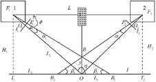
图1为本发明的测量系统布置示意图;Fig. 1 is a schematic layout of the measuring system of the present invention;
图2为本发明的测量系统左右两相机焦点距离L和偏角φ标定示意图。Fig. 2 is a schematic diagram of the calibration of the focus distance L and deflection angle φ of the left and right cameras of the measurement system of the present invention.
具体实施方式Detailed ways
本发明提出的一种河工模型试验三维地形的测量方法,其特征在于,采用两台参数相同的数码相机,一台连续激光矩形点阵示踪光斑发射装置,以及分别与两台数码相机相连的一台计算机;所述连续激光矩形点阵示踪光斑发射装置由连续激光器和微调光栅所组成;该微调光栅在河工模型床面上投射出不同间距及大小的矩形点阵示踪光斑,其中矩形点阵示踪光斑中心点为定位点O;A method for measuring three-dimensional topography of a river engineering model test proposed by the present invention is characterized in that two digital cameras with the same parameters, a continuous laser rectangular lattice tracer spot emitting device, and two digital cameras respectively connected to each other are used. A computer; the continuous laser rectangular lattice tracer spot emitting device is composed of a continuous laser and a fine-tuning grating; the fine-tuning grating projects rectangular lattice tracer spots with different spacing and sizes on the bed surface of the river engineering model, wherein the rectangular lattice The center point of the dot matrix tracer spot is the positioning point O;
该方法,包括以下步骤:The method comprises the following steps:
1)首先进行相机焦距f、两相机两焦点距离L以及相机偏角φ标定:1) First, calibrate the focal length f of the camera, the focal length L of the two cameras, and the declination angle φ of the camera:
1-1)相机焦距f标定计算公式为:1-1) The calculation formula for camera focal length f calibration is:
式中,a为CCD较短一边的边长,y2指相机初始拍摄垂向最大高度,y1为相机沿其光轴轴向向后移动ΔX后所拍摄的垂向最大高度(y1>y2);In the formula, a is the side length of the shorter side of the CCD,y2 refers to the maximum vertical height of the initial shooting of the camera, andy1 is the maximum vertical height of the camera after moving backward along its optical axis by ΔX (y1 > y2 );
1-2)两焦点距离L标定为:
式中,L1为OB1的长度,O为定位点,B1为与点B在左相机成像面上具有相同像素坐标的床面上的一点,点B为在点O垂直向上y高度处的一点;角度α1为点O与左相机焦点F1的连线F1O与直线F1B1的夹角,角度β1为点O与点B1的连线B1O与直线B1F1的夹角,其中α1和β1在标定时计算出α1=arctan(O1P1/f),β1=arctan(y/L1),O1P1为床面上线段OB1在左相机像平面上的图像长度;In the formula, L1 is the length of OB1 , O is the positioning point, B1 is a point on the bed that has the same pixel coordinates as point B on the left camera imaging plane, and point B is at the y height vertically upward from point O ; the angle α1 is the angle between the line F1 O connecting point O and the left camera focus F1 and the line F1 B1 , and the angle β1 is the line B 1 O and the lineB connecting point O and point B11 The included angle of F1 , where α1 and β1 are calculated during calibration α1 =arctan(O1 P1 /f), β1 =arctan(y/L1 ), O1 P1 is the bed surface line Image length of segment OB1 on the image plane of the left camera;
1-3)相机偏角φ标定为:1-3) The camera deflection angle φ is calibrated as:
φ=180-η=α1+β1φ=180-η=α1 +β1
式中,α1为直线F1O与直线F1B1之间的夹角;β1为直线B1O与直线B1F1之间的夹角;In the formula, α1 is the angle between the straight line F1 O and the straight line F1 B1 ; β1 is the angle between the straight line B1 O and the straight line B1 F1 ;
2)照相机标定完成后,在两相机焦点中间位置垂直向下安装连续激光矩形点阵示踪光斑发射装置,激光示踪光斑中心点为定位点O,定位点O在左右两相机像平面的成像分别为两相机像平面的中心点O1和O2;左右两相机成像面以中心点O1和O2为原点分别建立各自的直角坐标系x1O1y1和x2O2y2,床面上也以点O为中心点建立坐标系XOY,将两相机像平面及床面均分成四个象限,且每个象限所包含或所成像的激光示踪斑点一一对应;2) After the camera calibration is completed, install a continuous laser rectangular lattice tracer spot emission device vertically downward in the middle of the focus of the two cameras. The center point of the laser tracer spot is the positioning point O, and the positioning point O is imaged on the image plane of the left and right cameras. They are the center points O1 and O2 of the image planes of the two cameras respectively; the imaging planes of the left and right cameras take the center points O1 and O2 as the origin to establish their respective Cartesian coordinate systems x1 O1 y1 and x2 O2 y2 , the coordinate system XOY is also established with point O as the center point on the bed surface, and the image plane of the two cameras and the bed surface are divided into four quadrants, and the laser tracer spots contained or imaged in each quadrant correspond one-to-one;
3)对床面进行拍照,分别得到左右两相机所拍摄的系列照片;对所述系列照片进行噪声处理、畸变处理、像素二值化及对示踪光斑边缘检测的常规预处理,以及进行示踪光斑中心坐标的计算,再对示踪斑点进行匹配及特征提取,获得床面上同一个示踪光斑点P分别在左右两相机像平面上的像素坐标P1(m1p,n1p)和P2(m2p,n2p),再根据相机像素与CCD物理尺寸的转换关系,将示踪光斑点P在左右相机像平面上的像素坐标分别转化为像平面上的图像坐标P1(x1p,y1p)和P2(x2p,y2p);3) Take pictures of the bed surface, and obtain a series of photos taken by the left and right cameras respectively; perform noise processing, distortion processing, pixel binarization and conventional preprocessing on the tracer spot edge detection on the series of photos, and perform display The center coordinates of the tracking spot are calculated, and then the tracking spots are matched and feature extracted to obtain the pixel coordinates P1 (m1p , n1p ) and P2 (m2p , n2p ), and then according to the conversion relationship between camera pixels and CCD physical size, the pixel coordinates of the tracer spot P on the left and right camera image planes are respectively converted into image coordinates P1 (x1p , y1p ) and P2 (x2p , y2p );
4)以左相机焦点F1(0,0,0)为原点建立三维空间坐标系O-XYZ:F1F2为X轴、从点F1向下引垂线为Z轴,过点F1沿河床纵向方向为Y轴,根据数码相机的标定参数f、L、φ,将床面上每个示踪光斑点P在左右两相机像平面上的图像坐标P1(x1p,y1p)和P2(x2p,y2p)按转换公式换算为空间坐标系O-XYZ中的三维空间坐标P(XP,YP,ZP);4) Establish a three-dimensional space coordinate system O-XYZ with the left camera focus F1 (0, 0, 0) as the origin: F1 F2 is the X axis, a vertical line drawn downward from point F1 is the Z axis, passing through point F1 Along the longitudinal direction of the river bed is the Y axis, according to the calibration parameters f, L, φ of the digital camera, the image coordinates P1 (x1p , y1p ) and P2 (x2p , y2p ) are converted into three-dimensional space coordinates P(XP , YP , ZP ) in the space coordinate system O-XYZ according to the conversion formula;
激光示踪光斑图像坐标与三维空间坐标的转换公式为:The conversion formula of laser tracer spot image coordinates and three-dimensional space coordinates is:


式中,P1(x1p,y1p)和P2(x2p,y2p)分别为模型床面上激光示踪斑点P在左右两个像平面上的图像坐标;f为左右相机的焦距;L为左右相机的焦点间距;φ为相机偏角;θ1和θ2为虚拟角度,表示模型床面上的点P在平面I上的投影点PT与左右两相机焦点F1与点F2的连线F1PT和F2PT分别与线段F1F2和F2F1的夹角,平面I为过直线F1F2且垂直于模型床面的平面;In the formula, P1 (x1p , y1p ) and P2 (x2p , y2p ) are the image coordinates of the laser tracer spot P on the model bed surface on the left and right image planes respectively; f is the focal length of the left and right cameras ;L isthe focal distance of the leftand right cameras; φ isthe camera deflection angle; The angle between the connection line F1PT and F2PT of
5),以床面上所有激光示踪光斑的三维空间坐标
以下将结合附图及实施例对本发明的一种河工模型试验三维地形的量测方法进行详细说明。A method for measuring three-dimensional topography of a river engineering model test according to the present invention will be described in detail below with reference to the accompanying drawings and embodiments.
本发明提出的河工模型试验三维地形的测量方法,采用两台参数相同的数码相机1、2,一台连续激光矩形点阵示踪光斑发射装置3和计算机,如图1所示;所述数码相机为高分辨率定焦的两台同参数佳能照相机、所述连续激光矩形点阵示踪光斑发射装置由2W的连续激光器和微调光栅所组成;所述计算机为计算河工模型床面上激光示踪点的三维空间坐标以及实现河工模型地形可视化的平台。The method for measuring the three-dimensional terrain of the river engineering model test proposed by the present invention adopts two
上述装置的各部件的具体实施例说明如下:The specific embodiment of each part of above-mentioned device is described as follows:
两台高分辨率定焦相机参数为:The parameters of the two high-resolution fixed-focus cameras are:
相机机身采用佳能(canon)EOS 500D:传感器类型:CMOS;传感器尺寸:22.3×14.9mm;有效像素:1510万(最高分辨率4752×3168);影像处理器:DIGIC 4;快门速度:1/60-1/4000秒,采用全自动模式;镜头采用135mm全画幅广角镜头;最大光圈F2.8;最小光圈F22;最近对焦距离0.25m;焦距范围20mm;放大倍率0.14倍;视角范围94度。The camera body adopts Canon EOS 500D: sensor type: CMOS; sensor size: 22.3×14.9mm; effective pixels: 15.1 million (maximum resolution 4752×3168); image processor: DIGIC 4; shutter speed: 1/ 60-1/4000 seconds, using fully automatic mode; the lens uses a 135mm full-frame wide-angle lens; the maximum aperture is F2.8; the minimum aperture is F22; the closest focusing distance is 0.25m; the focal length range is 20mm; the magnification is 0.14 times;
连续激光器和微调光栅参数如下:The continuous laser and fine-tuning grating parameters are as follows:
激光器型号为LW-GL-532nm,功率为2W,工作方式为CW,TTL,Analogue,功率稳定性<5%,发散角<1,束腰直径<3mm。The laser model is LW-GL-532nm, the power is 2W, the working mode is CW, TTL, Analogue, the power stability is less than 5%, the divergence angle is less than 1, and the beam waist diameter is less than 3mm.
微调光栅为常用的正交衍射光栅,由通过母板用激光刻蚀到超白浮法玻璃上投射出矩形点阵光斑的两个光学镜片构成,每个镜片厚度1.5mm,尺寸10×10mm,投射点阵100×100(投射光斑数量)。当连续激光经过两光学镜片时,微调两镜片之间的距离可以在河工模型床面上投射出不同间距及大小的矩形点阵示踪光斑,其中矩形点阵示踪光斑中心点为定位点O,其亮度最高,容易识别。The fine-tuning grating is a commonly used orthogonal diffraction grating, which is composed of two optical lenses that project a rectangular lattice spot on the ultra-clear float glass by laser etching through the motherboard. Each lens has a thickness of 1.5mm and a size of 10×10mm. The projected dot matrix is 100×100 (number of projected spots). When the continuous laser passes through the two optical lenses, fine-tuning the distance between the two lenses can project rectangular lattice tracer spots with different spacing and sizes on the bed surface of the river engineering model, where the center point of the rectangular lattice tracer spot is the positioning point O , which has the highest brightness and is easy to identify.
计算机配置参数如下:The computer configuration parameters are as follows:
CPU性能不低于Intel奔腾4处理器、内存不低于512M、主板配备标准串口卡、操作系统版本不低于Windows XP。The CPU performance is not lower than Intel Pentium 4 processor, the memory is not lower than 512M, the motherboard is equipped with a standard serial port card, and the operating system version is not lower than Windows XP.
本发明方法,包括以下步骤:The inventive method comprises the following steps:
1)首先进行相机焦距f、两相机两焦点距离L以及相机偏角φ的标定:如图1所示,在数码相机安装时,根据河工模型的大小,调整左右两数码相机之间的距离、相机与床面的垂直高度H及其偏角φ(左右两数码相机像平面N1、N2的中垂线与水平线F1F2的夹角),最终实现两台数码相机的拍照范围基本重叠,可采用多套系统覆盖整个河工模型;1) First, calibrate the focal length f of the camera, the focal length L of the two cameras, and the camera deflection angle φ: as shown in Figure 1, when the digital camera is installed, adjust the distance between the left and right digital cameras according to the size of the river engineering model. The vertical height H between the camera and the bed surface and its deflection angle φ (the angle between the vertical line of the image planes N1 and N2 of the left and right digital cameras and the horizontal line F1 F2 ) finally realize that the shooting range of the two digital cameras is basically Overlapping, multiple systems can be used to cover the entire river model;
其中:in:
1-1)相机焦距f标定方法:1-1) Camera focal length f calibration method:
将数码相机固定在大型车床移动平台上,在数码相机正前方垂直安装一个精密网格板;移动车床的平台,拍摄网格板的图像,记录移动的距离Δx;根据几何条件解算出焦距f,焦距f的计算公式为:Fix the digital camera on the mobile platform of a large lathe, and install a precision grid plate vertically in front of the digital camera; move the platform of the lathe, take images of the grid plate, and record the moving distance Δx; calculate the focal length f according to the geometric conditions, The formula for calculating the focal length f is:
式中,a为CCD较短一边的边长,y2指相机初始拍摄垂向最大高度,y1为相机沿其光轴轴向向后移动ΔX后所拍摄的垂向最大高度(y1>y2);In the formula, a is the side length of the shorter side of the CCD,y2 refers to the maximum vertical height of the initial shooting of the camera, andy1 is the maximum vertical height of the camera after moving backward along its optical axis by ΔX (y1 > y2 );
1-2)两焦点距离L标定:
具体方法如图2所示,对于选定的数码相机和定焦镜头,确立焦距f和CCD的物理尺寸与像素的关系(总像素除以CCD尺寸得到每一像素的实际的物理长度);即在现场安装时,两个相机对称相向安装,两摄像机的像平面中垂线F1O、F2O共面且该面垂直于地面,其中定位点O在两相机像平面的成像均为两相机像平面的中心点;Concrete method as shown in Figure 2, for selected digital camera and fixed-focus lens, establish the relation of the physical size of focal length f and CCD and pixel (total pixel is divided by CCD size and obtains the actual physical length of each pixel); Namely During on-site installation, the two cameras are installed symmetrically facing each other, and the vertical lines F1 O and F2 O of the image planes of the two cameras are co-planar and perpendicular to the ground. The center point of the camera image plane;
过点O作一条直线l,该直线在两相机像平面的成像分别为两相机的像平面N1和N2的中心线l1和l2,设两相机焦点F1和F2在直线l上的垂直投影为点T1和T2。在数码相机景深允许的范围内,从点O垂直向上y高度处设置一点B,记录点B在左相机像平面上的像素坐标(X,Y),根据该像素坐标确定出在直线l上的点B1(点B1和点B在左相机像平面的像素坐标相同,均为点P1的像素坐标)。测量O、B1的距离为L1,计算角度β1(∠F1B1O):Draw a straight line l through the point O, and the imaging of the straight line on the image planes of the two cameras are the centerlines l1 and l2 of the image planes N1 and N2 of the two cameras, respectively. Let the focal points F1 and F2 of the two cameras lie on the straight line l The vertical projection on is points T1 and T2 . Within the range allowed by the depth of field of the digital camera, set a point B at the height y vertically upward from point O, record the pixel coordinates (X, Y) of point B on the image plane of the left camera, and determine the position on the line l according to the pixel coordinates Point B1 (the pixel coordinates of point B1 and point B on the image plane of the left camera are the same, both are the pixel coordinates of point P1 ). Measure the distance between O and B1 as L1 , and calculate the angle β1 (∠F1 B1 O):
点O和点B1左相机像平面的成像分别为O1和P1,根据CCD尺寸及像素坐标的换算公式计算出O1P1的长度,进而计算出α1(∠P1F1O1)的大小(arctan(O1O1/f))。已知α1、β1和L1,则:The imaging planes of the left camera at point O and point B1 are O1 and P1 respectively. According to the conversion formula of CCD size and pixel coordinates, the length of O1 P1 is calculated, and then α1 (∠P1 F1 O1 ) the size of (arctan(O1 O1 /f)). Given α1 , β1 and L1 , then:
η=180-α1-β1 (3)η=180-α1 -β1 (3)
其中,η为∠F1OB1,L2为OF1的长度。由此可以计算出OT1的长度L3:Wherein, η is ∠F1 OB1 , and L2 is the length of OF1 . From this the length L3 of OT1 can be calculated:
L3=L2cos(180-η) (5)L3 =L2 cos(180-η) (5)
由于相机对称安装,可得两相机焦点之间的距离L为:Since the cameras are installed symmetrically, the distance L between the focal points of the two cameras can be obtained as:
1-3)相机偏角φ的标定:φ=α1+β11-3) Calibration of camera deflection angle φ: φ=α1 +β1
由于直线F1F2与直线B1B2平行,可得相机偏角:Since the straight line F1 F2 is parallel to the straight line B1 B2 , the camera deflection angle can be obtained as:
φ=180-η=α1+β1 (7)φ=180-η=α1 +β1 (7)
2)照相机标定完成后,在两相机焦点中间位置垂直向下安装连续激光矩形点阵示踪光斑发射装置,根据拍照范围微调光栅,在床面上形成大小适宜,分布均匀、清晰识别的矩形点阵激光示踪光斑,激光示踪光斑中心点为定位点O,定位点O在左右两相机像平面的成像分别为两相机像平面的中心点O1和O2;左右两相机成像面以中心点O1和O2为原点分别建立各自的直角坐标系x1O1y1和x2O2y2,床面上也以点O为中心点建立坐标系XOY,将两相机像平面及床面均分成四个象限,且每个象限所包含或所成像的激光示踪斑点一一对应;2) After the camera calibration is completed, a continuous laser rectangular dot matrix tracer spot emission device is installed vertically downward in the middle of the focus of the two cameras, and the grating is fine-tuned according to the photographing range to form rectangular spots of suitable size, uniform distribution, and clear identification on the bed surface An array of laser tracer spots, the center point of the laser tracer spot is the positioning point O, and the imaging of the positioning point O on the image planes of the left and right cameras are the center points O1 and O2 of the image planes of the two cameras respectively; The points O1 and O2 are used as the origin to establish their respective Cartesian coordinate systems x1 O1 y1 and x2 O2 y2 , and the coordinate system XOY is also established with point O as the center point on the bed, and the two camera image planes and The bed surface is divided into four quadrants, and the laser tracer spots contained or imaged in each quadrant correspond to each other;
3)上述所有设备稳定布置后,对床面进行拍照,分别得到左右两相机所拍摄的系列照片;对所述系列照片进行噪声处理、畸变处理、像素二值化及对示踪光斑边缘检测的常规预处理,以及进行示踪光斑中心坐标的计算(可采用如质心法、最小二乘法、椭圆中心修正法),再对激光示踪斑点进行匹配及特征提取(采用经典的特征点匹配及提取技术),获得床面上同一个示踪光斑(如点P)在左右两相机像平面上的像素坐标P1(m1p,n1p)和P2(m2p,n2p),再根据相机像素与CCD物理尺寸的转换关系,将示踪光斑在左右相机像平面上的像素坐标转化为对应的照片的图像坐标P1(x1p,y1p)和P2(x2p,y2p);3) After all the above-mentioned equipments are stably arranged, take pictures of the bed surface, and obtain a series of pictures taken by the left and right cameras respectively; perform noise processing, distortion processing, pixel binarization and edge detection of the tracer spot on the series of pictures Routine preprocessing, and calculation of the center coordinates of the tracer spot (such as centroid method, least square method, ellipse center correction method can be used), and then matching and feature extraction of the laser tracer spot (using classic feature point matching and extraction technology), obtain the pixel coordinates P1 (m1p , n1p ) and P2 (m2p , n2p ) of the same tracer spot (such as point P) on the bed surface on the image plane of the left and right cameras, and then according to the camera The conversion relationship between pixels and CCD physical size, transforming the pixel coordinates of the tracer spot on the image plane of the left and right cameras into the image coordinates P1 (x1p , y1p ) and P2 (x2p , y2p ) of the corresponding photos;
4)以左相机焦点F1(0,0,0)为原点建立三维空间坐标系O-XYZ:F1F2为X轴、从点F1向下引垂线为Z轴,过点F1沿河床纵向方向为Y轴,如附图1所示;根据数码相机的标定参数f、L、φ,将床面上每个示踪光斑点P在左右两相机像平面上的图像坐标P1(x1p,y1p)和P2(x2p,y2p)按转换公式(8)换算为空间坐标系O-XYZ中的三维空间坐标P(XP,YP,ZP);4) Establish a three-dimensional space coordinate system O-XYZ with the left camera focus F1 (0, 0, 0) as the origin: F1 F2 is the X axis, a vertical line drawn downward from point F1 is the Z axis, passing through point F1 Along the longitudinal direction of the river bed is the Y axis, as shown in Figure 1; according to the calibration parameters f, L, φ of the digital camera, the image coordinates of each tracer spot P on the bed surface on the image planes of the left and right cameras P1 (x1p , y1p ) and P2 (x2p , y2p ) are converted into three-dimensional space coordinates P(XP , YP , ZP ) in the space coordinate system O-XYZ according to the conversion formula (8);
激光示踪光斑图像坐标与三维空间坐标的转换公式为:The conversion formula of laser tracer spot image coordinates and three-dimensional space coordinates is:

式中,P1(x1p,y1p)和P2(x2p,y2p)分别为模型床面上激光示踪斑点P在左右两个像平面上的图像坐标;f为左右相机的焦距;L为左右相机的焦点间距;φ为相机偏角;θ1和θ2为虚拟角度,表示模型床面上的点P在平面I上的投影点PT与左右两相机焦点F1与点F2的连线F1PT和F2PT分别与线段F1F2和F2F1的夹角,平面I为过直线F1F2且垂直于模型床面的平面;In the formula, P1 (x1p , y1p ) and P2 (x2p , y2p ) are the image coordinates of the laser tracer spot P on the model bed surface on the left and right image planes respectively; f is the focal length of the left and right cameras ;L isthe focal distance of the leftand right cameras; φ isthe camera deflection angle; The angle between the connection line F1PT and F2PT of
以第四象限为例推求激光示踪斑点图像坐标与空间坐标的转换公式(8)如下:Taking the fourth quadrant as an example, the conversion formula (8) of laser tracer spot image coordinates and space coordinates is calculated as follows:
根据两个相数码机和连连续激光矩形点阵示踪光斑发射装置的安装,左右两相机焦点F1(0,0,0)和F2(L,0,0)与激光示踪斑定位点O三点所在的平面与模型床面垂直,记F1、F2、O三点确定的平面为平面I。选择河工模型床面上第四象限某一个激光示踪光斑点P,点P在左右两相机像平面中的成像分别为点P1和点P2,点P1和点P2投影到I平面分别为点K1(在线l1上)和点K2(在线l2上),床面上的点P在平面I上的投影为点PT,P1相对于左相机像平面中心点O1的偏角∠O1F1K1记为ψ1,同样记∠P1F1K1为

由此计算出河工模型床面上激光示踪光斑点P在以F1(0,0,0)为原点空间坐标系的三维空间坐标;From this, the three-dimensional space coordinates of the laser tracer spot P on the bed surface of the river engineering model in the space coordinate system with F1 (0, 0, 0) as the origin are calculated;

式中,
5)通过计算机内设的绘图程序(选用常用的软件,如Auto CAD、Matlab、EXCEL等),以床面上所有激光示踪光斑的三维空间坐标
在实际应用中,如果测量的河工模型范围较大,可以布设多套本发明的系统,各系统之间有一定的重复范围,通过各系统之间坐标的旋转与平移来对各系统的数据进行集成、最后重构河工模型完整的三维地形图。In practical applications, if the range of the river engineering model to be measured is relatively large, multiple sets of systems of the present invention can be deployed, and there is a certain range of repetition between the systems, and the data of each system can be processed through the rotation and translation of the coordinates between the systems. Integrate and finally reconstruct the complete 3D topographic map of the river engineering model.
Claims (1)

Priority Applications (1)
| Application Number | Priority Date | Filing Date | Title |
|---|---|---|---|
| CN201210033188.0ACN102538763B (en) | 2012-02-14 | 2012-02-14 | Method for measuring three-dimensional terrain in river model test |
Applications Claiming Priority (1)
| Application Number | Priority Date | Filing Date | Title |
|---|---|---|---|
| CN201210033188.0ACN102538763B (en) | 2012-02-14 | 2012-02-14 | Method for measuring three-dimensional terrain in river model test |
Publications (2)
| Publication Number | Publication Date |
|---|---|
| CN102538763Atrue CN102538763A (en) | 2012-07-04 |
| CN102538763B CN102538763B (en) | 2014-03-12 |
Family
ID=46346256
Family Applications (1)
| Application Number | Title | Priority Date | Filing Date |
|---|---|---|---|
| CN201210033188.0AExpired - Fee RelatedCN102538763B (en) | 2012-02-14 | 2012-02-14 | Method for measuring three-dimensional terrain in river model test |
Country Status (1)
| Country | Link |
|---|---|
| CN (1) | CN102538763B (en) |
Cited By (17)
| Publication number | Priority date | Publication date | Assignee | Title |
|---|---|---|---|---|
| CN103148842A (en)* | 2013-02-04 | 2013-06-12 | 国家海洋局第二海洋研究所 | Shallow sea sand wave area multi-beam sounding terrain reconstruction method based on remote sensing image features |
| CN103617649A (en)* | 2013-11-05 | 2014-03-05 | 北京江宜科技有限公司 | Camera self-calibration technology-based river model topography measurement method |
| CN103983982A (en)* | 2014-05-27 | 2014-08-13 | 哈尔滨工业大学 | Automobile infrared ray/visible light double camera laser radar device |
| CN104267444A (en)* | 2014-10-23 | 2015-01-07 | 淮海工学院 | Real-time three-dimensional imaging device for hole |
| CN104567796A (en)* | 2013-10-29 | 2015-04-29 | 江西盛泰光学有限公司 | 3D shooting ranging method |
| CN104864849A (en)* | 2014-02-24 | 2015-08-26 | 电信科学技术研究院 | Visual navigation method and device and robot |
| CN105423940A (en)* | 2015-12-25 | 2016-03-23 | 同济大学 | Subway tunnel structure cross section deformation rapid detection device |
| WO2018227576A1 (en)* | 2017-06-16 | 2018-12-20 | 深圳市大疆创新科技有限公司 | Method and system for detecting ground shape, method for drone landing, and drone |
| CN109725640A (en)* | 2018-12-18 | 2019-05-07 | 天津理工大学 | A 3D road reconstruction method in autonomous driving based on stereo vision and laser grating |
| CN110030955A (en)* | 2018-01-11 | 2019-07-19 | 天津大学 | A kind of seabed roughness measurement method based on the algorithm that shapes from shade |
| CN110608746A (en)* | 2018-06-14 | 2019-12-24 | 大众汽车有限公司 | Method and apparatus for determining the position of a motor vehicle |
| CN111552289A (en)* | 2020-04-28 | 2020-08-18 | 苏州高之仙自动化科技有限公司 | Detection method, virtual radar device, electronic apparatus, and storage medium |
| CN112066950A (en)* | 2020-07-24 | 2020-12-11 | 北京空间机电研究所 | A single-center projection conversion method for a surveying and mapping camera with parallel multiple optical axes |
| CN112461496A (en)* | 2020-09-09 | 2021-03-09 | 福建省水利水电勘测设计研究院 | Visual processing method for erosion and deposition test results of hydraulic and river model |
| CN113280790A (en)* | 2021-05-07 | 2021-08-20 | 王亚超 | Building mapping device based on laser positioning |
| CN113406851A (en)* | 2021-05-31 | 2021-09-17 | 南方电网调峰调频发电有限公司 | Hydraulic model installation device and method |
| CN114255396A (en)* | 2021-11-01 | 2022-03-29 | 南方电网数字电网研究院有限公司 | Power transmission line environment reconstruction method, system and device and controller |
Citations (1)
| Publication number | Priority date | Publication date | Assignee | Title |
|---|---|---|---|---|
| CN1116704A (en)* | 1994-12-23 | 1996-02-14 | 清华大学 | Image acquisition system and image processing method in flow field measurement of river engineering model test |
- 2012
- 2012-02-14CNCN201210033188.0Apatent/CN102538763B/ennot_activeExpired - Fee Related
Patent Citations (1)
| Publication number | Priority date | Publication date | Assignee | Title |
|---|---|---|---|---|
| CN1116704A (en)* | 1994-12-23 | 1996-02-14 | 清华大学 | Image acquisition system and image processing method in flow field measurement of river engineering model test |
Non-Patent Citations (2)
| Title |
|---|
| 王兴奎等: "《图像处理技术在河工模型试验流场量测中的应用》", 《泥沙研究》* |
| 马志敏等: "《河工模型三维地形测量系统的研制》", 《长江科学院院报》* |
Cited By (25)
| Publication number | Priority date | Publication date | Assignee | Title |
|---|---|---|---|---|
| CN103148842A (en)* | 2013-02-04 | 2013-06-12 | 国家海洋局第二海洋研究所 | Shallow sea sand wave area multi-beam sounding terrain reconstruction method based on remote sensing image features |
| CN103148842B (en)* | 2013-02-04 | 2014-11-05 | 国家海洋局第二海洋研究所 | Shallow sea sand wave area multi-beam sounding terrain reconstruction method based on remote sensing image features |
| CN104567796A (en)* | 2013-10-29 | 2015-04-29 | 江西盛泰光学有限公司 | 3D shooting ranging method |
| CN103617649A (en)* | 2013-11-05 | 2014-03-05 | 北京江宜科技有限公司 | Camera self-calibration technology-based river model topography measurement method |
| CN103617649B (en)* | 2013-11-05 | 2016-05-11 | 北京江宜科技有限公司 | A kind of river model topographic survey method based on Camera Self-Calibration technology |
| CN104864849A (en)* | 2014-02-24 | 2015-08-26 | 电信科学技术研究院 | Visual navigation method and device and robot |
| US9886763B2 (en) | 2014-02-24 | 2018-02-06 | China Academy Of Telecommunications Technology | Visual navigation method, visual navigation device and robot |
| CN103983982A (en)* | 2014-05-27 | 2014-08-13 | 哈尔滨工业大学 | Automobile infrared ray/visible light double camera laser radar device |
| CN104267444A (en)* | 2014-10-23 | 2015-01-07 | 淮海工学院 | Real-time three-dimensional imaging device for hole |
| US10731967B2 (en) | 2015-12-25 | 2020-08-04 | Tongji University | System for quickly detecting tunnel deformation |
| CN105423940A (en)* | 2015-12-25 | 2016-03-23 | 同济大学 | Subway tunnel structure cross section deformation rapid detection device |
| WO2017107334A1 (en)* | 2015-12-25 | 2017-06-29 | 同济大学 | Subway tunnel structure cross section deformation rapid detection device |
| WO2018227576A1 (en)* | 2017-06-16 | 2018-12-20 | 深圳市大疆创新科技有限公司 | Method and system for detecting ground shape, method for drone landing, and drone |
| CN110030955A (en)* | 2018-01-11 | 2019-07-19 | 天津大学 | A kind of seabed roughness measurement method based on the algorithm that shapes from shade |
| CN110608746A (en)* | 2018-06-14 | 2019-12-24 | 大众汽车有限公司 | Method and apparatus for determining the position of a motor vehicle |
| CN109725640A (en)* | 2018-12-18 | 2019-05-07 | 天津理工大学 | A 3D road reconstruction method in autonomous driving based on stereo vision and laser grating |
| CN111552289A (en)* | 2020-04-28 | 2020-08-18 | 苏州高之仙自动化科技有限公司 | Detection method, virtual radar device, electronic apparatus, and storage medium |
| CN112066950A (en)* | 2020-07-24 | 2020-12-11 | 北京空间机电研究所 | A single-center projection conversion method for a surveying and mapping camera with parallel multiple optical axes |
| CN112066950B (en)* | 2020-07-24 | 2022-10-14 | 北京空间机电研究所 | Multi-optical-axis parallel mapping camera single-center projection conversion method |
| CN112461496A (en)* | 2020-09-09 | 2021-03-09 | 福建省水利水电勘测设计研究院 | Visual processing method for erosion and deposition test results of hydraulic and river model |
| CN112461496B (en)* | 2020-09-09 | 2023-08-18 | 福建省水利水电勘测设计研究院有限公司 | Visual processing method for hydraulic and river model dredging test results |
| CN113280790A (en)* | 2021-05-07 | 2021-08-20 | 王亚超 | Building mapping device based on laser positioning |
| CN113280790B (en)* | 2021-05-07 | 2023-08-15 | 王亚超 | Building mapping device based on laser positioning |
| CN113406851A (en)* | 2021-05-31 | 2021-09-17 | 南方电网调峰调频发电有限公司 | Hydraulic model installation device and method |
| CN114255396A (en)* | 2021-11-01 | 2022-03-29 | 南方电网数字电网研究院有限公司 | Power transmission line environment reconstruction method, system and device and controller |
Also Published As
| Publication number | Publication date |
|---|---|
| CN102538763B (en) | 2014-03-12 |
Similar Documents
| Publication | Publication Date | Title |
|---|---|---|
| CN102538763A (en) | Method for measuring three-dimensional terrain in river model test | |
| CN103971406B (en) | Submarine target three-dimensional rebuilding method based on line-structured light | |
| CN110031829B (en) | An accurate ranging method for targets based on monocular vision | |
| CN101334267B (en) | Method and Device for Vector Coordinate Transformation Calibration and Error Correction of Digital Video Measuring Probe | |
| CN102003938B (en) | Thermal state on-site detection method for large high-temperature forging | |
| CN102183214B (en) | Light detection method for large-aperture aspherical mirror structure | |
| CN103617649B (en) | A kind of river model topographic survey method based on Camera Self-Calibration technology | |
| CN103993547B (en) | A kind of method that datum mark line laser pavement track detection system detects pavement track | |
| CN108120392A (en) | Bubble three-dimension measuring system and method in biphase gas and liquid flow | |
| CN102063718A (en) | Field calibration and precision measurement method for spot laser measuring system | |
| CN111854622B (en) | A large field of view optical dynamic deformation measurement method | |
| CN105067023A (en) | Panorama three-dimensional laser sensor data calibration method and apparatus | |
| CN105698767A (en) | Underwater measuring method based on vision | |
| CN106978774A (en) | A kind of road surface pit automatic testing method | |
| CN105163065B (en) | A kind of traffic speed-measuring method based on video camera front-end processing | |
| CN103487033A (en) | River surface photographic surveying method based on height-change homography | |
| CN116977576B (en) | Three-dimensional terrain reconstruction method of sandy bed based on underwater images | |
| Torkan et al. | High-resolution photogrammetry to measure physical aperture of two separated rock fracture surfaces | |
| CN105203030A (en) | Monitoring method of micro displacement at engineering site | |
| CN104296681B (en) | Dimensional topography method for sensing based on laser dot-matrix mark | |
| CN115423884B (en) | Video camera attitude angle calibration method by utilizing river section water edge line | |
| CN116202423A (en) | A two-dimensional laser positioning method based on laser triangulation | |
| Yu et al. | An out-of-focus image calibration method based on accurate positioning of concentric circle projection center | |
| CN204924273U (en) | Three -dimensional laser sensor data calibrating device of panorama | |
| CN102999895A (en) | Method for linearly solving intrinsic parameters of camera by aid of two concentric circles |
Legal Events
| Date | Code | Title | Description |
|---|---|---|---|
| C06 | Publication | ||
| PB01 | Publication | ||
| C10 | Entry into substantive examination | ||
| SE01 | Entry into force of request for substantive examination | ||
| GR01 | Patent grant | ||
| GR01 | Patent grant | ||
| CF01 | Termination of patent right due to non-payment of annual fee | ||
| CF01 | Termination of patent right due to non-payment of annual fee | Granted publication date:20140312 Termination date:20180214 |