CN102530047B - baby carrier - Google Patents
baby carrierDownload PDFInfo
- Publication number
- CN102530047B CN102530047BCN2010106131446ACN201010613144ACN102530047BCN 102530047 BCN102530047 BCN 102530047BCN 2010106131446 ACN2010106131446 ACN 2010106131446ACN 201010613144 ACN201010613144 ACN 201010613144ACN 102530047 BCN102530047 BCN 102530047B
- Authority
- CN
- China
- Prior art keywords
- seat
- support tube
- carrying device
- engaging
- baby carrying
- Prior art date
- Legal status (The legal status is an assumption and is not a legal conclusion. Google has not performed a legal analysis and makes no representation as to the accuracy of the status listed.)
- Active
Links
Images


Classifications
- B—PERFORMING OPERATIONS; TRANSPORTING
- B62—LAND VEHICLES FOR TRAVELLING OTHERWISE THAN ON RAILS
- B62B—HAND-PROPELLED VEHICLES, e.g. HAND CARTS OR PERAMBULATORS; SLEDGES
- B62B7/00—Carriages for children; Perambulators, e.g. dolls' perambulators
- B62B7/008—Carriages for children; Perambulators, e.g. dolls' perambulators for two or more children
- B—PERFORMING OPERATIONS; TRANSPORTING
- B62—LAND VEHICLES FOR TRAVELLING OTHERWISE THAN ON RAILS
- B62B—HAND-PROPELLED VEHICLES, e.g. HAND CARTS OR PERAMBULATORS; SLEDGES
- B62B7/00—Carriages for children; Perambulators, e.g. dolls' perambulators
- B62B7/04—Carriages for children; Perambulators, e.g. dolls' perambulators having more than one wheel axis; Steering devices therefor
- B62B7/14—Carriages for children; Perambulators, e.g. dolls' perambulators having more than one wheel axis; Steering devices therefor with detachable or rotatably-mounted body
- B62B7/142—Means for securing the body to the frame
- B—PERFORMING OPERATIONS; TRANSPORTING
- B62—LAND VEHICLES FOR TRAVELLING OTHERWISE THAN ON RAILS
- B62B—HAND-PROPELLED VEHICLES, e.g. HAND CARTS OR PERAMBULATORS; SLEDGES
- B62B9/00—Accessories or details specially adapted for children's carriages or perambulators
- B62B9/28—Auxiliary dismountable seats ; Additional platforms for children in standing-up position
- B—PERFORMING OPERATIONS; TRANSPORTING
- B62—LAND VEHICLES FOR TRAVELLING OTHERWISE THAN ON RAILS
- B62B—HAND-PROPELLED VEHICLES, e.g. HAND CARTS OR PERAMBULATORS; SLEDGES
- B62B7/00—Carriages for children; Perambulators, e.g. dolls' perambulators
- B62B7/04—Carriages for children; Perambulators, e.g. dolls' perambulators having more than one wheel axis; Steering devices therefor
- B62B7/044—Carriages for children; Perambulators, e.g. dolls' perambulators having more than one wheel axis; Steering devices therefor three wheeled
Landscapes
- Engineering & Computer Science (AREA)
- Chemical & Material Sciences (AREA)
- Combustion & Propulsion (AREA)
- Transportation (AREA)
- Mechanical Engineering (AREA)
- Health & Medical Sciences (AREA)
- Public Health (AREA)
- Child & Adolescent Psychology (AREA)
- General Health & Medical Sciences (AREA)
- Carriages For Children, Sleds, And Other Hand-Operated Vehicles (AREA)
Abstract
Description
Translated fromChinese【技术领域】【Technical field】
本发明是关于一种婴儿承载装置,特别是关于一种设有后座椅的婴儿承载装置。The present invention relates to an infant carrying device, in particular to an infant carrying device provided with a rear seat.
【背景技术】【Background technique】
目前婴儿车在构造设计上,为了能够不只能承载一位婴儿,已经有兼具前座椅及后座椅之构造设计的婴儿车。At present, in the structural design of baby carriages, in order to carry more than one baby, there are already baby carriages with the structural design of the front seat and the rear seat.
目前坊间具有后座椅的婴儿车,其构造设计与只具有前座椅的婴儿车的差异在于婴儿车的底管上还加设了一个后座椅支撑管及一后座椅,其中后座椅固定于后座椅支撑管。此外,具有后座椅的婴儿车还可细分为二类,第一类是后座椅无法拆卸的婴儿车,而第二类是后座椅可以拆卸的婴儿车,其中后座椅可以拆卸的婴儿车,其拆卸机构的设计,在于婴儿车之底管组接有一弹簧片,该弹簧片的一端具有一突部,而后座椅支撑管的下端设有一与突部对应的卡合孔。当后座椅支撑管锁定在婴儿车的底管上时,弹簧片之突部乃卡合于底管上的卡合孔。如果大人要将后座椅拆下,则按压弹簧片之突部,使得弹簧片之突部脱离底管上的卡合孔,便可将后座椅支撑管连同后座椅由底管上拆卸下来。然而,上述这二类具有后座椅之婴儿车,其后座椅无法选择性拆除或是座椅拆除时不容易操作拆除机构,且后座椅的倾斜角度都无法调整,所以仍有改善的空间。At present, there are baby carriages with rear seats in the market. The difference between its structural design and those with only front seats is that a rear seat support tube and a rear seat are added to the bottom tube of the baby carriage. The seat is fixed to the rear seat support tube. In addition, strollers with a rear seat can be further subdivided into two categories, the first category being strollers with a non-removable rear seat, and the second category being strollers with a removable rear seat, in which the rear seat is detachable The design of the disassembly mechanism of the stroller is that the bottom tube of the stroller is assembled with a spring piece, one end of the spring piece has a protrusion, and the lower end of the rear seat support tube is provided with an engaging hole corresponding to the protrusion. When the rear seat support tube is locked on the bottom tube of the stroller, the protruding portion of the spring leaf is engaged with the engaging hole on the bottom tube. If an adult wants to remove the rear seat, press the protruding part of the spring leaf to make the protruding part of the spring leaf disengage from the engaging hole on the bottom tube, and then the rear seat support tube and the rear seat can be disassembled from the bottom tube down. However, in the above two types of baby carriages with rear seats, the rear seat cannot be selectively removed or the removal mechanism is not easy to operate when the seat is removed, and the inclination angle of the rear seat cannot be adjusted, so there is still room for improvement. space.
有鉴于此,本发明为一种能改善上述缺失,提供了一种兼具后座椅可拆卸以及可调整后座椅之倾斜角度的婴儿车。In view of this, the present invention is a kind of stroller which can improve the above-mentioned deficiency, and provides a stroller with detachable rear seat and adjustable rear seat inclination angle.
【发明内容】【Content of invention】
本发明一目的在于提供一婴儿承载装置,婴儿承载装置之后座椅除了可拆卸之外,亦可调整倾斜角度。An object of the present invention is to provide an infant carrying device, the rear seat of the infant carrying device is not only detachable, but also the tilt angle can be adjusted.
依据本发明的一实施例,提供一种婴儿承载装置,其特征在于:包括:一底支架,该底支架包含有一底管及一固定座,该固定座固接于该底管;以及一可拆卸座椅,其包含有一支撑管及装设于该支撑管二端的一耦合件;其中,该支撑管的角度可相对于该耦合件作调整,且该耦合件可透过一卡合件移离地与该固定座相锁定,使该可拆卸座椅以可拆卸的方式装设在该底支架。According to one embodiment of the present invention, there is provided a baby carrying device, which is characterized in that it includes: a bottom bracket, the bottom bracket includes a bottom tube and a fixing seat, and the fixing seat is fixed to the bottom tube; Disassemble the seat, which includes a support tube and a coupling piece installed at both ends of the support tube; wherein, the angle of the support tube can be adjusted relative to the coupling piece, and the coupling piece can be moved through a locking piece The ground is locked with the fixed seat, so that the detachable seat is detachably installed on the bottom frame.
所述的婴儿承载装置,其特征在于:该耦合件包含一管状的连接部,当该耦合件与该固定座相锁定时,该连接部插入至该固定座,且该卡合件分别通过该连接部与该固定座的对应开孔。The above baby carrying device is characterized in that: the coupling part includes a tubular connecting part, when the coupling part is locked with the fixing seat, the connecting part is inserted into the fixing seat, and the engaging parts pass through the fixing seat respectively. The corresponding opening of the connecting portion and the fixing seat.
所述的婴儿承载装置,其特征在于:该卡合件设置于该连接部内,并可介于一卡合位置与一释锁位置之间位移。The above-mentioned baby carrying device is characterized in that: the engaging part is disposed in the connecting part, and can be displaced between an engaging position and an unlocking position.
所述的婴儿承载装置,其特征在于:该卡合件是藉由一弹性作用偏移至该卡合位置。The above-mentioned baby carrying device is characterized in that: the engaging part is biased to the engaging position by an elastic action.
所述的婴儿承载装置,其特征在于:该座椅还设有一释锁机构,透过该释锁机构的操作,可驱动该卡合件释锁。The above-mentioned baby carrying device is characterized in that: the seat is also provided with a release mechanism, through the operation of the release mechanism, the locking part can be driven to release the lock.
所述的婴儿承载装置,其特征在于:该释锁机构包括:一驱动件,为设置于该连接部内并位于邻近该卡合件;一操作件,活动地设置于该支撑管上且与该连接部具有一段距离;及一牵引缆索,其沿该支撑管延伸、并连接于该驱动件与该操作件之间;其中,该操作件在移动时可透过该牵引缆索及该驱动件的传动促使该卡合件释锁。The above-mentioned baby carrying device is characterized in that: the release mechanism includes: a driving part arranged in the connecting part and adjacent to the engaging part; an operating part movably arranged on the support tube and connected with the The connecting portion has a distance; and a traction cable, which extends along the support tube and is connected between the driving part and the operating part; wherein the operating part can pass through the traction cable and the driving part when moving. The transmission prompts the locking part to be released.
所述的婴儿承载装置,其特征在于:该卡合件可平行于一第一方向位移,而该驱动件可平行于一第二方向位移,其中第二方向大约垂直于该第一方向。The above-mentioned baby carrying device is characterized in that: the engaging part can displace parallel to a first direction, and the driving part can displace parallel to a second direction, wherein the second direction is approximately perpendicular to the first direction.
所述的婴儿承载装置,其特征在于:该驱动件设有一开口,而该卡合件为通过该开口滑动地装设。The above-mentioned baby carrying device is characterized in that: the driving part is provided with an opening, and the engaging part is slidably installed through the opening.
所述的婴儿承载装置,其特征在于:该支撑管与该耦合件透过一枢轴相枢接,且该耦合件设有复数卡合槽,其中,该复数卡合槽为相对于该枢轴设置于不同径向,该支撑管则可与该复数卡合槽其中一个相卡合,从而锁定该座椅在不同角度。The above-mentioned infant carrying device is characterized in that: the support tube and the coupling part are pivotally connected through a pivot, and the coupling part is provided with a plurality of engaging grooves, wherein the plurality of engaging grooves are opposite to the pivot. The shafts are arranged in different radial directions, and the support tube can be engaged with one of the plurality of engaging grooves, thereby locking the seat at different angles.
所述的婴儿承载装置,其特征在于:该支撑管设有一卡合端部,其中,该卡合端部可相对于该枢轴径向地滑动,以卡合或脱离该复数卡合槽的其中一个。The above-mentioned baby carrying device is characterized in that: the supporting tube is provided with an engaging end, wherein the engaging end can slide radially relative to the pivot to engage or disengage from the plurality of engaging grooves. One of the.
所述的婴儿承载装置,其特征在于:该卡合端部为该支撑管的末端,且该枢轴是穿过该支撑管的一长形槽,使该支撑管可相对于该枢轴滑动。The above baby carrying device is characterized in that: the engaging end is the end of the support tube, and the pivot is an elongated slot passing through the support tube, so that the support tube can slide relative to the pivot .
所述的婴儿承载装置,其特征在于:该拆卸座椅为后座椅,且该婴儿承载装置还设有一位于该后座椅之前的前座椅。The above-mentioned infant carrying device is characterized in that: the detachable seat is a rear seat, and the infant carrying device is also provided with a front seat located in front of the rear seat.
依据本发明的另一实施例,提供一种婴儿承载装置,其特征在于:包括:一底支架,该底支架包含有一底管及一固定座,该固定座固接于该底管;以及一座椅,包含一支撑管,该支撑管可装设于该固定座,以将该座椅定位于该底支架上;其中,该固定座与该支撑管为透过一卡合件相锁定,而且该支撑管设有一释锁机构,透过该释锁机构的操作可促使该卡合件由一卡合位置位移至一释锁位置,藉此,该座椅以可拆卸的方式装设于该底支架上。According to another embodiment of the present invention, a baby carrying device is provided, which is characterized in that it includes: a bottom bracket, the bottom bracket includes a bottom tube and a fixing seat, and the fixing seat is fixed to the bottom tube; and a The seat includes a support tube, and the support tube can be installed on the fixed seat to position the seat on the bottom bracket; wherein, the fixed seat and the support tube are locked through a snap-fitting piece, And the support tube is provided with a release mechanism, through the operation of the release mechanism, the engaging member can be moved from an engaging position to an releasing position, whereby the seat is detachably mounted on the on the bottom bracket.
所述的婴儿承载装置,其特征在于:该固定座包含一管状端部,其中,该支撑管可套接于该管状端部外,以将该座椅固定于该底支架。The above-mentioned infant carrying device is characterized in that: the fixing seat includes a tubular end, wherein the support tube can be sleeved outside the tubular end to fix the seat to the bottom frame.
所述的婴儿承载装置,其特征在于:该卡合件设置于该管状端部中,该卡合件的一突部可卡合于该管状端部与该支撑管的对应开孔,以将该支撑管与该固定座相锁定。The baby carrying device is characterized in that: the engaging part is arranged in the tubular end, and a protrusion of the engaging part can be engaged with the corresponding opening of the tubular end and the supporting tube, so as to The support tube is locked with the fixing base.
所述的婴儿承载装置,其特征在于:该卡合件为呈弯曲的弹片。The above-mentioned infant carrying device is characterized in that: the engaging part is a curved elastic piece.
所述的婴儿承载装置,其特征在于:该释锁机构包括一操作件,透过该操作件位移,可顶推该卡合件的该突部脱离卡合。The above-mentioned baby carrying device is characterized in that: the release mechanism includes an operating part, through the displacement of the operating part, the protrusion of the engaging part can be pushed to disengage.
所述的婴儿承载装置,其特征在于:该卡合件设置于该支撑管末端,该释锁机构包括:一驱动件,为设置邻近于该卡合件;一操作件,活动地设置于该支撑管上且与该连接部具有一段距离;及一牵引缆索,其沿该支撑管延伸、并连接于该驱动件与该操作件之间;其中,该操作件在移动时可透过该牵引缆索及该驱动件的传动促使该卡合件释锁。The above-mentioned baby carrying device is characterized in that: the engaging part is arranged at the end of the support tube, and the release mechanism includes: a driving part, which is arranged adjacent to the engaging part; an operating part, which is movably arranged on the There is a distance from the connecting part on the support tube; and a traction cable, which extends along the support tube and is connected between the driving part and the operating part; wherein, the operating part can pass through the traction cable when moving The transmission of the cable and the driving part promotes the unlocking of the engaging part.
所述的婴儿承载装置,其特征在于该座椅包含有装设于支撑管二端的一耦合件;其中,该支撑管的角度可相对于该耦合件作调整。The above-mentioned infant carrying device is characterized in that the seat includes a coupling piece installed at two ends of the support tube; wherein, the angle of the support tube can be adjusted relative to the coupling piece.
所述的婴儿承载装置,其特征在于:该座椅为后座椅,且该婴儿承载装置还设有一位于该后座椅之前的前座椅。The above-mentioned infant carrying device is characterized in that: the seat is a rear seat, and the infant carrying device is also provided with a front seat located in front of the rear seat.
【附图说明】【Description of drawings】
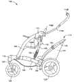
图1绘示本发明一实施例所提供的婴儿承载装置的立体图。FIG. 1 is a perspective view of an infant carrying device provided by an embodiment of the present invention.
图2绘示图1的婴儿承载装置的侧视图。FIG. 2 is a side view of the infant carrier of FIG. 1 .
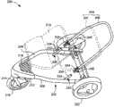
图3绘示图1的婴儿承载装置所设有的可拆卸座椅的示意图。FIG. 3 is a schematic diagram of a detachable seat provided in the infant carrying device of FIG. 1 .
图4为绘示可拆卸座椅的支撑管与耦合件相连接的示意图。FIG. 4 is a schematic diagram illustrating the connection between the support tube of the detachable seat and the coupling member.
图5及图6为绘示可拆卸座椅相对于耦合件的调整动作的示意图。5 and 6 are schematic diagrams illustrating the adjustment action of the detachable seat relative to the coupling member.
图7至图10为绘示可拆卸座椅与底支架的组接示意图。7 to 10 are schematic diagrams illustrating the assembly of the detachable seat and the bottom frame.
图11为绘示卡合件处于释锁示状态的意图。Fig. 11 is a schematic view showing the locking part in the unlocked state.
图12绘示依据本发明另一实施例所提供的婴儿承载装置的立体图。FIG. 12 is a perspective view of an infant carrying device according to another embodiment of the present invention.
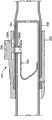
图13绘示图12的可拆卸座椅的支撑管与固定座相锁定的剖面示意图。FIG. 13 is a schematic cross-sectional view of the locking of the support tube and the fixing seat of the detachable seat of FIG. 12 .
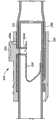
图14为绘示释锁机构的动作示意图。FIG. 14 is a schematic diagram illustrating the action of the release mechanism.
100婴儿承载装置100 infant carrier
102底支架 104前支撑管102
106后支撑管 108第一座椅106
108A座板 108B背板
110把手 110A侧管110
110B横管 112收合机构110B
114第二座椅 116底管114
118转接件 120前轮支架118
124前轮 126踏板124
128后轮 129置物篮128
130避震装置 132座椅调整机构130 shock absorber 132 seat adjustment mechanism
142支撑管 144座椅体142
146耦合件 146A本体146
146B连接部 150固定座
152释锁机构 154操作件152
156牵引缆索 160内部空间156
162枢轴 162A、162B卡合槽162
163A、163B挡面 164卡合端部163A,
166长形槽 168弹簧件166
169直杆 169A凸缘169
170定位槽 172开孔170
174卡合件 174A凸缘174
174B斜面 176弹簧件174B
177开孔 178驱动件177
180导轨 182卡孔180
184开口 186凸肋184
186A斜面 188开口186A
190开口190 openings
D1第一方向 D2第二方向D1 first direction D2 second direction
200婴儿承载装置200 infant carrier
202底支架 204座椅202
206支撑管 206A开孔206
207座椅体 208底管207
212转接件 214前轮支架212
216前轮 218踏板216
219座椅 220后轮219
230固定座 232管状端部230 Fixing
234卡合件 234A突部234
236开孔 240释锁机构236
242套筒 244操作件242
【具体实施方式】【Detailed ways】
图1及图2分别绘示本发明一实施例所提供的婴儿承载装置100的立体图及侧视图,其中该婴儿承载装置100为婴儿车。该婴儿承载装置100包括有一底支架102、一对前支撑管104、一对后支撑管106、第一座椅108、一把手110、一对收合机构112、及第二座椅114。FIG. 1 and FIG. 2 respectively show a perspective view and a side view of an
该底支架102包含有二底管116,在此实施例中该二底管116是一体成型而呈外观近似一V字形,而使该二底管116的前端部的间距相较该二底管116的后端部的间距为近。该二底管116的前端部组接于一转接件118,该转接件118的下方枢接有一前轮支架120,该前轮支架120上枢接有一前轮124,藉由前轮支架120的转动可改变婴儿车的行进方向。该二底管116的前端部之间的转接件118上还可形成一近似三角形的踏板126,以供婴幼儿乘坐于第一座椅108时置放脚部。至于各底管116的后端部则组接有一后轮128。该二底管116之间更可跨设一置物篮129,置物篮129位于踏板126后下方,置物篮129局部或全部加设塑胶板以提供婴幼儿乘坐于第二座椅114时置放脚部。The
该对前支撑管104分别设置于婴儿承载装置100的左右二侧,而各该前支撑管104的下端部枢接于底管116的前端部。该对后支撑管106分别设置于婴儿承载装置100的左右二侧,而各后支撑管106的下端部枢接于底管116的后端部,并设有一避震装置130。The pair of
该把手110包含有二侧管110A及一横管110B,该横管110B连接该二侧管110A之间,而大人可握住横管110B推动或拉回婴儿车。The
各该前支撑管104的上端部、各该后支撑管106的上端部、以及各该侧管110A的下端部分别组接于各该收合机构112。当婴儿承载装置100在使用状态时,收合机构112锁定前支撑管104及把手110。反之,当婴儿承载装置100要转为收合状态时,收合机构112解除对前支撑管104及把手110的锁定,使前支撑管104、后支撑管106、及把手110可相对枢转靠近。The upper end of each of the
第一座椅108设于该对前支撑管104之间、以及该对后支撑管106之间,作为婴儿承载装置100的前座椅。第一座椅108包含有一座板108A及一背板108B,背板108B的下端部连接于座板108A的后端部,而座板108A的前端部枢接于该对前支撑管104之间。为调整第一座椅108的倾斜角度,婴儿承载装置100在第一座椅108的左右两侧分别设置有一座椅调整机构132。各座椅调整机构132的上端部及下端部分别组接于该收合机构112及座板108A的后端部。The
第二座椅114位于第一座椅108的后侧、并装设于底支架102上,作为婴儿承载装置100的后座椅。依据本发明,第二座椅114为可拆卸的座椅,使第二座椅114依使用需求可选择性安装在底支架102、或自底支架102拆卸。The
图3为更详细绘示第二座椅114的示意图。如图1至图3所示,第二座椅114可包含有一支撑管142、及固定于支撑管142的座椅体144。支撑管142的外形近似一U字形,包含二侧端管及一横管。在此实施例中,二侧端管及横管可一体形成。另外,支撑管142在其左右二侧端管的末端各装设有一耦合件146。第二座椅114可藉由耦合件146移离地组装于底支架102上。FIG. 3 is a schematic diagram illustrating the
各耦合件146具有一本体146A、及凸出在本体146A一侧的连接部146B。本体146A设有一内部空间,在其中可活动地组接支撑管142的末端。连接部146B则为管状端部。连接部146B可插入至底管116上所设置的固定座150,并可透过其内侧的卡合件174(参考图7、图8)与固定座150相锁定,以便固定该第二座椅114在底支架102上。为便使用者操作卡合件的释锁,第二座椅114还设有一释锁机构152,其包括操作件154及牵引缆索156。有关于卡合件174及释锁机构152的结构,将在后续参照图7至图11做详细的叙述。Each
图4为绘示支撑管142与耦合件146相连接的示意图。该耦合件146的本体146A设有一内部空间160,而支撑管142的末端可容置在本体146A的内部空间160并透过枢轴162与耦合件146枢接,使支撑管142可相对于耦合件146枢转。FIG. 4 is a schematic diagram illustrating the connection between the
另外,本体146A的内部空间160亦设有复数卡合槽162A、162B,为相对于枢轴162排列在不同径向。支撑管142的末端设有卡合端部164。依据支撑管142相对于耦合件146的角度,卡合端部164可与不同卡合槽162A、162B卡合。为便进行卡合及释锁的动作,卡合端部164较佳可相对于枢轴162作径向移动。依据此实施例,卡合端部164可与支撑管142相固定(例如卡合端部164以支撑管142的末端组成),而枢轴162是穿过支撑管142中所设置的长形槽166,使支撑管142、卡合端部164可相对于枢轴162同步位移。此外,支撑管142内亦固设有一弹簧件168,用以促使卡合端部164卡合于卡合槽162A、162B。依据此实施例,弹簧件168可环绕支撑管142内所设置的直杆169,其中弹簧件168的一侧端与枢轴162抵接,弹簧件168的另一侧端则与直杆169的凸缘169A抵接。In addition, the
图5及图6为绘示第二座椅114相对于耦合件146的调整动作的示意图。为简化图示的内容,图5及图6仅绘示支撑管142代表第二座椅114部份。当拉动支撑管142时,可带动卡合端部164脱离卡合槽(例如卡合槽162A)并压缩弹簧件168。随后,带动第二座椅114相对于耦合件146绕枢轴162转动。当第二座椅114调整为欲设的角度后,释放支撑管142,让弹簧件168促使支撑管142及卡合端部164位移,致使卡合端部164与另一卡合槽(例如卡合槽162B)卡合。当卡合端部164卡合于卡合槽162B时,卡合槽162B的二相对侧挡面163A、163B可限制卡合端部164的枢转,为对应第二座椅114较后向调整的位置。当卡合端部164卡合于卡合槽162A时则为对应第二座椅114的较直立乘坐位置。FIG. 5 and FIG. 6 are schematic diagrams illustrating the adjustment action of the
在第二座椅114装设于底支架102之后,使用者可藉由前述的设计轻易地调整第二座椅114的座椅体144相对于底支架102的倾斜角度,以供婴儿最舒适的乘坐状态。After the
值得一提,本发明不限于前述实施例,亦可藉由其它设计实现卡合结构。例如,卡合端部亦可滑动地设置于支撑管142,并伸缩地突出支撑管142,且支撑管142还设有一释锁操作件、及连接在卡合端部与释锁操作件之间的缆索(未示)。透过释锁操作件的操作,可带动卡合端部相对于支撑管位移并脱离卡合;当座椅调整为欲设的角度后,弹簧件的作用可促使卡合端部恢复卡合状态。It is worth mentioning that the present invention is not limited to the foregoing embodiments, and other designs can also be used to realize the engaging structure. For example, the engaging end is also slidably arranged on the
图7至图10为绘示第二座椅114与底支架102的组接示意图。如图7所示,固定座150为固定于底支架102上,并设有一定位槽170、及位于定位槽170一侧壁的开孔172。耦合件146组接于第二座椅114的支撑管142,且耦合件146的连接部146B可插入至固定座150的定位槽170,从而将第二座椅114定位在底支架102上。当第二座椅114定位在底支架102上后(如图8所示),连接部146B所设置的卡合件174可透过弹性作用与开孔172卡合,进而使第二座椅114与底支架102相锁定。卡合件174可相对于耦合件146位移,以伸出于连接部146B、或往连接部146B内缩进,从而完成耦合件146与固定座150的卡合和释锁。7 to 10 are schematic diagrams illustrating the assembly of the
图9为绘示耦合件146透过卡合件174与固定座150相锁定的局部剖面示意图。卡合件174装设于耦合件146的连接部146B内,并可平行于第一方向D1滑动。弹簧件176是设置于卡合件174与连接部146B内侧壁之间。当连接部146B插入至固定座150的定位槽170后,弹簧件176可促使卡合件174伸出于连接部146B的开孔177并卡合于固定座150的对应开孔172,进而将第二座椅114与底支架102相锁定。FIG. 9 is a schematic partial cross-sectional view illustrating that the
为便驱动卡合件174的释锁,耦合件146的连接部146B内在邻近卡合件174还设有一驱动件178,其中驱动件178、牵引缆索156及操作件154(参照图3)组成释锁机构152。接着,同时参照图9及图10说明驱动件178、卡合件174的组接方式。连接部146B内固定有一导轨180,驱动件178则沿导轨180装设,使驱动件178可平行于一第二方向D2位移,其中第二方向D2与卡合件174的滑动方向D1相垂直。In order to drive the unlocking of the
如图10所示,驱动件178具有长形状。驱动件178的一侧端设有一卡孔182供牵引缆索156的一末端固定。驱动件178中亦设有一开口184、并在开口184的两侧分别设有凸肋186,其中各凸肋186分别具有斜面186A。As shown in FIG. 10, the
卡合件174为通过驱动件178的开口184滑动地装设,且卡合件174在邻近弹簧件176的一侧设有凸缘174A,而凸缘174A还设有与凸肋186的斜面186A相接触的斜面174B。因此,当驱动件178平行于第二方向D2位移时,藉由斜面186A、174B的相互顶推可导引卡合件174平行于第一方向D1位移。藉由前述的组装,可节省卡合件174、驱动件178所需的组装空间。The engaging
继续参照图8及图9,牵引缆索156可由连接部146B的一开口188伸出于耦合件146、由支撑管142的另一开口190进入支撑管142、沿支撑管142的内侧延伸、再与操作件154连接,使得操作件154可远离连接部146B滑动地设置于支撑管142上(如图3所示)。因此,大人可透过操作件154、牵引缆索156及驱动件178的传动而方便地驱动卡合件174的释锁。Continuing to refer to Fig. 8 and Fig. 9, the
图11为绘示卡合件174的释锁状态的示意图。当操作件154(参照图3)被拉动时,可透过牵引缆索156促使驱动件178平行于第二方向D2往上位移,而卡合件174透过斜面186A、174A的相互顶推则平行于第一方向D1往连接部146B内侧位移,从而使卡合件174由图9所示的卡合位置位移至图11的释锁位置,以致脱离开孔172的卡合。随后,大人可由固定座150轻易地拔出耦合件146的连接部146B,藉以拆卸第二座椅114。FIG. 11 is a schematic diagram illustrating an unlocked state of the engaging
若大人欲装设第二座椅114在底支架102上,则将耦合件146的连接部146B插入固定座150的定位槽170。藉由弹簧件176的作用,可促使卡合件174卡合于固定座150的开孔172,以致第二座椅114锁定在底支架102上。If an adult wants to install the
值得一提,前述的卡合件174及释锁机构152的设计不一定必须搭配可调整式的耦合件146使用。依据其他实施例,若第二座椅114不需要调整功能,相同的卡合件174及释锁机构152等结构亦可直接装设于支撑管142的管状端部(尤其卡合件174可设置于支撑管142的末端),而支撑管142可直接插入固定座150并由卡合件174直接锁定于固定座150,释锁机构152的操作则同样可驱动卡合件174的释锁。It is worth mentioning that the aforementioned designs of the engaging
图12绘示依据本发明另一实施例所提供的婴儿承载装置200的立体图,如图12所示,该婴儿承载装置200包含有一底支架202及一可移离装设于底支架202上的座椅204。在此实施例中座椅204可包含有一近似U形的支撑管206及一座椅体207(以虚线表示)。FIG. 12 shows a perspective view of an
底支架202可与前述实施例具有相同结构,包含有一体成型而呈外观近似一V字形的二底管208。该二底管208的前端部组接于一转接件212,转接件212的下方亦枢接有一前轮支架214,而前轮支架214上枢接有一前轮216,藉由前轮支架214的转动可改变婴儿车的行进方向。该二底管208的前端部之间的转接件212上还可形成一近似三角形的踏板218,以供婴幼儿乘坐于另一座椅219(以虚线表示)时置放脚部,而座椅219的位置位于座椅204之前方,使座椅219、204可分别作为婴儿承载装置200的前、后座椅。至于底管208的后端部则组接有一后轮220。The
底支架202还包含有二固定座230,而该二固定座230在此时实施例中分别固接于该二底管208的后端部。各该固定座230包含有一管状端部232及一卡合件234。支撑管206的末端可分别套接管状端部234,并藉由卡合件234加以锁定,从而固定座椅204在底支架202上。The
图13为绘示座椅204的支撑管206与固定座230相锁定的剖面示意图。卡合件234设置于固定座230的管状端部232内。依据此实施例,卡合件234为呈弯曲的弹片,其一侧端设有突部234A伸出于管状端部232的开孔236。当支撑管206的末端套接管状端部232后,卡合件234的突部234A可藉由卡合件234本身的弹性卡合于支撑管206上所设置的对应开孔206A,使座椅204在无法自底支架202移离。FIG. 13 is a schematic cross-sectional view illustrating the locking of the
此外,支撑管206左右两侧的末端还分别装设有一释锁机构240,透过释锁机构240的操作可促使该卡合件234的释锁。如图13所示,释锁机构240可包括一套筒242、及由套筒242伸出的弹性操作件244,其中操作件244位于对应开孔206A的位置。In addition, the ends of the left and right sides of the
图14为绘示释锁机构240的动作示意图。当座椅204固定于底支架202上时,卡合件234的突部234A卡合于支撑管206的开孔206A,且操作件244位于对应于突部234A的位置。若使用者需要将座椅204自底支架202拆卸,则可压按操作件244朝向突部234A移动,使操作件232顶推卡合件234由图13所示的卡合位置位移至图14所示的释锁位置。因此,卡合件234的突部234A可脱离支撑管206的开孔206A,致使座椅204可由底支架202轻易地拆卸。FIG. 14 is a schematic diagram illustrating the action of the
透过本发明所提供的婴儿承载装置,大人不但可以透过操作件方便地拆卸后座椅之外,亦可在后座椅组装于车架上时,可随需求调整后座椅的倾斜角度。虽然前述实施例以后座椅为例,但本发明所设计的可拆卸座椅结构可依据需求应用于婴儿承载装置的任何座椅。Through the baby carrying device provided by the present invention, adults can not only easily disassemble the rear seat through the operating parts, but also adjust the inclination angle of the rear seat as required when the rear seat is assembled on the frame . Although the aforementioned embodiment is an example of a rear seat, the detachable seat structure designed by the present invention can be applied to any seat of an infant carrying device according to requirements.
以上叙述依据本发明多个不同实施例,其中各项特征可以单一或不同结合方式实施。因此,本发明实施方式之揭露为阐明本发明原则之具体实施例,应不拘限本发明于所揭示的实施例。进一步言之,先前叙述及其附图仅为本发明示范之用,并不受其限囿。其他元件之变化或组合皆可能,且不悖于本发明之精神与范围。The above description is based on multiple different embodiments of the present invention, wherein each feature can be implemented singly or in different combinations. Therefore, the disclosure of the embodiments of the present invention is a specific example to illustrate the principles of the present invention, and the present invention should not be limited to the disclosed embodiments. Furthermore, the foregoing descriptions and accompanying drawings are merely illustrative of the present invention and are not intended to limit it. Changes or combinations of other elements are possible without departing from the spirit and scope of the present invention.
Claims (10)
Priority Applications (5)
| Application Number | Priority Date | Filing Date | Title |
|---|---|---|---|
| CN201310407209.5ACN103496392B (en) | 2010-12-20 | 2010-12-20 | Baby carrying device |
| CN2010106131446ACN102530047B (en) | 2010-12-20 | 2010-12-20 | baby carrier |
| US13/329,656US8936261B2 (en) | 2010-12-20 | 2011-12-19 | Child carrier apparatus |
| GB1121993.8AGB2486813B (en) | 2010-12-20 | 2011-12-20 | Child carrier apparatus |
| GB1304515.8AGB2499736B (en) | 2010-12-20 | 2011-12-20 | Child carrier apparatus |
Applications Claiming Priority (1)
| Application Number | Priority Date | Filing Date | Title |
|---|---|---|---|
| CN2010106131446ACN102530047B (en) | 2010-12-20 | 2010-12-20 | baby carrier |
Related Child Applications (1)
| Application Number | Title | Priority Date | Filing Date |
|---|---|---|---|
| CN201310407209.5ADivisionCN103496392B (en) | 2010-12-20 | 2010-12-20 | Baby carrying device |
Publications (2)
| Publication Number | Publication Date |
|---|---|
| CN102530047A CN102530047A (en) | 2012-07-04 |
| CN102530047Btrue CN102530047B (en) | 2013-11-27 |
Family
ID=45572779
Family Applications (2)
| Application Number | Title | Priority Date | Filing Date |
|---|---|---|---|
| CN2010106131446AActiveCN102530047B (en) | 2010-12-20 | 2010-12-20 | baby carrier |
| CN201310407209.5AActiveCN103496392B (en) | 2010-12-20 | 2010-12-20 | Baby carrying device |
Family Applications After (1)
| Application Number | Title | Priority Date | Filing Date |
|---|---|---|---|
| CN201310407209.5AActiveCN103496392B (en) | 2010-12-20 | 2010-12-20 | Baby carrying device |
Country Status (3)
| Country | Link |
|---|---|
| US (1) | US8936261B2 (en) |
| CN (2) | CN102530047B (en) |
| GB (2) | GB2499736B (en) |
Families Citing this family (27)
| Publication number | Priority date | Publication date | Assignee | Title |
|---|---|---|---|---|
| WO2008127128A1 (en)* | 2007-04-13 | 2008-10-23 | Phil And Teds Most Excellent Buggy Company Limited | Collapsible two seat perambulator |
| CN102256856B (en)* | 2008-12-04 | 2014-06-11 | 戴那米克品牌股份有限公司 | Seat attachment for a stroller |
| US11577771B2 (en) | 2008-12-04 | 2023-02-14 | Baby Jogger, LLC | Removable seat attachment for a stroller |
| US9944305B2 (en) | 2008-12-04 | 2018-04-17 | Baby Jogger, LLC | Removable seat attachment for a stroller |
| CN102530047B (en)* | 2010-12-20 | 2013-11-27 | 明门香港股份有限公司 | baby carrier |
| ES2396886B1 (en)* | 2011-01-03 | 2014-01-20 | Jane, S.A. | Chassis for strollers with two seats. |
| GB201211205D0 (en)* | 2012-06-25 | 2012-08-08 | Icandy World Ltd | Apparatus and method |
| GB201215739D0 (en)* | 2012-09-04 | 2012-10-17 | Rohl Stephanie | Child seat |
| CN202843043U (en)* | 2012-09-07 | 2013-04-03 | 明门(中国)幼童用品有限公司 | Handle folding structure and children carrying basket with the same |
| USD763535S1 (en)* | 2013-04-11 | 2016-08-09 | Truper Sa De Cv | Trolley wheel |
| CN104228921B (en)* | 2013-06-13 | 2016-09-14 | 明门香港股份有限公司 | Connecting device and infant care equipment with same |
| DE102014213383A1 (en) | 2014-07-09 | 2016-01-14 | Fidlock Gmbh | Manually operated closure device with delay device |
| CN105172869A (en)* | 2015-08-10 | 2015-12-23 | 南京工业职业技术学院 | Baby carriage capable of being changed into child bicycle |
| CA174441S (en)* | 2015-10-07 | 2018-01-02 | Starship Tech Oü | Delivery robot |
| US9889872B2 (en)* | 2016-03-28 | 2018-02-13 | Ignio LLC | Multi-function mobility device |
| EP3490874A4 (en)* | 2016-07-27 | 2020-04-15 | Kolcraft Enterprises, Inc. | Foldable strollers and related methods |
| CN109715473B (en) | 2016-07-27 | 2022-03-04 | 考可拉夫特公司 | Stroller with removable seat and related method |
| US10994763B2 (en) | 2016-07-27 | 2021-05-04 | Kolcraft Enterprises, Inc. | Foldable strollers with removeable seats and related methods |
| AU2016417658B2 (en)* | 2016-08-01 | 2023-09-14 | NZP1027 Ltd | Transportation apparatus |
| USD821265S1 (en) | 2017-03-23 | 2018-06-26 | Starship Technologies Oü | Vehicle |
| WO2018215581A1 (en) | 2017-05-26 | 2018-11-29 | Starship Technologies Oü | A battery and a system for swapping and/or charging a battery of a mobile robot |
| US11052934B2 (en) | 2017-07-27 | 2021-07-06 | Kolcraft Enterprises, Inc. | Foldable strollers and related methods |
| EP3659104B1 (en) | 2017-07-28 | 2024-01-17 | Starship Technologies OÜ | Device and system for secure package delivery by a mobile robot |
| GB2571092A (en)* | 2018-02-15 | 2019-08-21 | Donna Obrien | A device for infant transport |
| US10752278B2 (en)* | 2018-03-23 | 2020-08-25 | Monahan Products, LLC | Suspension system for stroller |
| CN109204430B (en)* | 2018-11-07 | 2023-12-05 | 东莞市铭心科技服务有限公司 | Locking type connecting structure and baby carriage |
| US11332180B2 (en)* | 2020-01-29 | 2022-05-17 | Guava Family, Inc. | Stroller having compact folding and suspension system |
Citations (3)
| Publication number | Priority date | Publication date | Assignee | Title |
|---|---|---|---|---|
| CN2897763Y (en)* | 2006-05-04 | 2007-05-09 | 东莞市寮步齐家日用品设计服务部 | A shopping trolley for children with double front and rear seats |
| CN200999058Y (en)* | 2006-10-26 | 2008-01-02 | 中山市隆成日用制品有限公司 | Standing board at tail of baby carriage |
| CN201511991U (en)* | 2009-04-17 | 2010-06-23 | 中山市隆成日用制品有限公司 | Baby carriage with second seat mechanism |
Family Cites Families (63)
| Publication number | Priority date | Publication date | Assignee | Title |
|---|---|---|---|---|
| US4872692A (en)* | 1988-06-03 | 1989-10-10 | Prodigy Corp. | Convertible carriage with biased wheel retraction |
| US5018405A (en) | 1990-08-02 | 1991-05-28 | Sunshon Molding Co., Ltd. | Angle adjustment device for handle of stroller |
| US5676386A (en)* | 1995-10-30 | 1997-10-14 | Huang; Li-Chu Chen | Stroller in combination with a safety seat assembly |
| US5722682A (en)* | 1996-06-27 | 1998-03-03 | Wang; Morgan | Foldable two-seater stroller |
| US5947555A (en)* | 1996-11-22 | 1999-09-07 | Kolcraft Enterprises, Inc. | Infant seat and stroller coupling system |
| JPH10291480A (en)* | 1997-04-18 | 1998-11-04 | Masaharu Miyake | Attachment for baby car |
| NL1009753C2 (en)* | 1998-07-28 | 2000-02-01 | Royalty Bugaboo S A R L | Buggy. |
| US6530591B2 (en)* | 2001-08-07 | 2003-03-11 | Mien Chen Huang | Double-seat frame structure for baby stroller |
| JP3986826B2 (en)* | 2002-01-15 | 2007-10-03 | コンビ株式会社 | Stroller with reclining mechanism |
| GB2385301B (en)* | 2002-02-13 | 2004-05-19 | Red Lan | Foldable stroller |
| ES1053703Y (en)* | 2003-01-09 | 2003-11-16 | Jane Sa | DEVICE FOR THE ENVIRONMENTAL COUPLING OF SEATS AND COATS-COT IN CHILDREN'S CARS. |
| US6991248B2 (en)* | 2003-05-05 | 2006-01-31 | Dynamic Brands, Llc | Folding baby stroller system and method |
| NL1027054C2 (en)* | 2004-09-16 | 2006-03-20 | Bugaboo Design And Sales B V | Buggy. |
| CN2787534Y (en)* | 2005-02-02 | 2006-06-14 | 蓝贯仁 | Baby stroller with carrier attachment |
| US7210690B2 (en)* | 2005-05-17 | 2007-05-01 | Yi-Cheng Tan | Direction-limiting device for stroller |
| US7367581B2 (en)* | 2005-08-26 | 2008-05-06 | Link Treasure Limited | Baby stroller frame with seat direction changing mechanism |
| TWM288269U (en)* | 2005-09-29 | 2006-03-01 | Link Treasure Ltd | One-hand controlled seat inclination structure for baby trolley |
| GB0521832D0 (en) | 2005-10-26 | 2005-12-07 | Micralite Ltd | Transporter |
| US7681894B2 (en)* | 2006-02-14 | 2010-03-23 | Jane, S.A. | Device for fitting seats and the like to the chassis of baby carriages |
| CN2918182Y (en) | 2006-02-18 | 2007-07-04 | 陈明泽 | Skeleton connection locking mechanism of a baby carriage |
| US7267359B1 (en)* | 2006-06-08 | 2007-09-11 | Link Treasure Limited | Collapsible stroller frame |
| JP2009544791A (en)* | 2006-07-26 | 2009-12-17 | コーニンクレッカ フィリップス エレクトロニクス エヌ ヴィ | YAG-based ceramic garnet material containing at least one multisite element |
| US7753398B2 (en)* | 2006-08-25 | 2010-07-13 | Link Treasure Limited | Baby stroller frame with seat direction changing mechanism |
| US20080054579A1 (en)* | 2006-09-01 | 2008-03-06 | Jui-Ching Liu | Golf travel bag |
| US8485546B2 (en)* | 2006-09-08 | 2013-07-16 | Lerado (Zhong Shan) Industrial Co., Ltd. | Foldable baby stroller frame |
| CN200957826Y (en) | 2006-10-26 | 2007-10-10 | 中山市隆成日用制品有限公司 | Infant rides with one-handed release mechanism |
| DE202006017557U1 (en)* | 2006-11-17 | 2007-03-01 | Ilinko Ltd. | Personal supporting fixture for personal transport carriage, has frame whereby angle between first frame component and second frame component is independently adjusted |
| DE202006017551U1 (en)* | 2006-11-17 | 2007-03-01 | Ilinko Ltd. | Frame and children accommodating device e.g. seat, connecting device for e.g. perambulator, has locking unit and snap-fit that are movable in same direction from locking position into unlocking position by actuation of pushbuttons |
| TWM325260U (en)* | 2006-12-13 | 2008-01-11 | Link Treasure Ltd | Pivotal base for a canopy frame |
| GB0703517D0 (en)* | 2007-02-23 | 2007-04-04 | Klever Kids Ltd | Child carrying apparatus |
| US8915524B2 (en)* | 2007-03-08 | 2014-12-23 | GM Global Technology Operations LLC | Vehicle door auxiliary latch release |
| GB2468796A (en) | 2007-04-13 | 2010-09-22 | Phil And Teds Most Excellent B | Collapsible two seat perambulator |
| WO2008127128A1 (en)* | 2007-04-13 | 2008-10-23 | Phil And Teds Most Excellent Buggy Company Limited | Collapsible two seat perambulator |
| US7789402B2 (en)* | 2007-06-01 | 2010-09-07 | Graco Children's Products Inc. | Stroller with seat height adjustment |
| US8251382B2 (en)* | 2007-06-06 | 2012-08-28 | Wonderland Nurserygoods Co., Ltd. | Stroller and seat assembly mechanism for a stroller |
| US8128119B2 (en)* | 2007-07-31 | 2012-03-06 | Graco Children's Products Inc. | Stroller with foldable frame and adjustable handle |
| US7401803B1 (en)* | 2007-08-28 | 2008-07-22 | Chin-I Lai | Stroller |
| DE102007044833A1 (en)* | 2007-09-18 | 2009-04-02 | Otto Bock Healthcare Ip Gmbh & Co. Kg | Baby carriage |
| US7686323B2 (en)* | 2007-10-19 | 2010-03-30 | Ting-Yu Chen | Baby stroller with portable cradle |
| US7938435B2 (en)* | 2008-03-28 | 2011-05-10 | Cosco Management, Inc. | Juvenile stroller with removable child carrier |
| NL1035275C2 (en)* | 2008-04-09 | 2009-10-12 | Maxi Miliaan Bv | Assembly comprising an undercarriage and a child's seat that can be detachably connected to the undercarriage, such an undercarriage as well as such a child's seat. |
| KR100911552B1 (en)* | 2008-05-16 | 2009-08-10 | 현대자동차주식회사 | Lever take-off device for trunk lid |
| US20100013281A1 (en)* | 2008-07-16 | 2010-01-21 | Hung-Tsun Chen | Dual-seat frame of baby stroller |
| US8448977B2 (en)* | 2008-08-01 | 2013-05-28 | Graco Children's Products Inc. | Storage latch and reversible handle for a stroller |
| US8240700B2 (en)* | 2008-08-15 | 2012-08-14 | Artsana Usa, Inc. | Stroller with travel seat attachment |
| US8469388B2 (en)* | 2008-09-25 | 2013-06-25 | Tray Vous Llc | Detachable tray accessory for stroller |
| GB0818605D0 (en)* | 2008-10-10 | 2008-11-19 | Scs London Ltd | Apparatus and method |
| CN101722975B (en)* | 2008-10-23 | 2012-09-05 | 明门香港股份有限公司 | Infant carrier with multi-directional use positions |
| US8029014B2 (en)* | 2008-10-31 | 2011-10-04 | Graco Children's Products Inc. | Stroller with synchronized seat height adjustment |
| US20100127480A1 (en)* | 2008-11-26 | 2010-05-27 | Graco Children's Products Inc. | Foldable Stroller and Fold Linkage for Same |
| US8474854B2 (en)* | 2009-03-24 | 2013-07-02 | Graco Children's Products Inc. | Foldable stroller and fold interlock mechanism |
| DE102010011551B4 (en)* | 2009-03-13 | 2014-10-23 | Graco Children's Products, Inc. | Baby carriage and seat arrangement |
| GB2468767B (en)* | 2009-03-16 | 2011-07-06 | Graco Childrens Prod Inc | Stroller adapter for an infant car seat |
| CN102030026B (en)* | 2009-09-24 | 2012-10-31 | 明门香港股份有限公司 | Infant carrier with bi-directional use and method of operation thereof |
| CN102101489B (en)* | 2009-12-18 | 2013-07-03 | 明门香港股份有限公司 | Infant Carrier with Adjustable Push Bar |
| US8157286B2 (en)* | 2010-02-19 | 2012-04-17 | Chin-I Lai | Stroller |
| CN102275608B (en)* | 2010-06-14 | 2013-01-30 | 明门(中国)幼童用品有限公司 | Safety protection device for preventing accidental folding and infant trolley |
| CN102530047B (en)* | 2010-12-20 | 2013-11-27 | 明门香港股份有限公司 | baby carrier |
| US8905428B2 (en)* | 2011-03-21 | 2014-12-09 | Graco Children's Products Inc. | Foldable stroller and fold joint for a foldable stroller |
| CN202294365U (en)* | 2011-04-15 | 2012-07-04 | 克斯克管理公司 | Children constraining system |
| US8465045B2 (en)* | 2011-05-17 | 2013-06-18 | Chin-I Lai | Baby carriage |
| CN202283142U (en)* | 2011-09-29 | 2012-06-27 | 中山市隆成日用制品有限公司 | High dining chair |
| US8596669B2 (en)* | 2011-11-07 | 2013-12-03 | Unique Product & Design Co., Ltd. | Baby stroller |
- 2010
- 2010-12-20CNCN2010106131446Apatent/CN102530047B/enactiveActive
- 2010-12-20CNCN201310407209.5Apatent/CN103496392B/enactiveActive
- 2011
- 2011-12-19USUS13/329,656patent/US8936261B2/enactiveActive
- 2011-12-20GBGB1304515.8Apatent/GB2499736B/enactiveActive
- 2011-12-20GBGB1121993.8Apatent/GB2486813B/enactiveActive
Patent Citations (3)
| Publication number | Priority date | Publication date | Assignee | Title |
|---|---|---|---|---|
| CN2897763Y (en)* | 2006-05-04 | 2007-05-09 | 东莞市寮步齐家日用品设计服务部 | A shopping trolley for children with double front and rear seats |
| CN200999058Y (en)* | 2006-10-26 | 2008-01-02 | 中山市隆成日用制品有限公司 | Standing board at tail of baby carriage |
| CN201511991U (en)* | 2009-04-17 | 2010-06-23 | 中山市隆成日用制品有限公司 | Baby carriage with second seat mechanism |
Non-Patent Citations (1)
| Title |
|---|
| JP特开平10-291480A 1998.11.04 |
Also Published As
| Publication number | Publication date |
|---|---|
| GB2499736A (en) | 2013-08-28 |
| CN103496392B (en) | 2016-03-02 |
| US8936261B2 (en) | 2015-01-20 |
| CN102530047A (en) | 2012-07-04 |
| GB201304515D0 (en) | 2013-04-24 |
| CN103496392A (en) | 2014-01-08 |
| GB2499736B (en) | 2014-04-02 |
| GB201121993D0 (en) | 2012-02-01 |
| GB2486813A (en) | 2012-06-27 |
| US20120153583A1 (en) | 2012-06-21 |
| GB2486813B (en) | 2013-07-24 |
Similar Documents
| Publication | Publication Date | Title |
|---|---|---|
| CN102530047B (en) | baby carrier | |
| CN101722975B (en) | Infant carrier with multi-directional use positions | |
| CN105313940B (en) | Baby carriage device | |
| CN102101491B (en) | foldable infant carrier | |
| CN108068871B (en) | Baby carriage | |
| CN107284506A (en) | Folding seat group and baby carriage | |
| CN102211609B (en) | baby carrier | |
| CN108791451A (en) | Stroller device | |
| US10322739B2 (en) | Baby carriage and carriage frame thereof | |
| CN102275608A (en) | Anti-accidental folding safety protection device and baby stroller | |
| CN109131520B (en) | Child cart with simple folding operation | |
| CN101712332A (en) | Baby carriage and combination of baby carriage and automobile seat | |
| CN108556896B (en) | Baby stroller seat easy to fold and store | |
| CN102233893B (en) | Infant carrier with front and rear bidirectional use states and method of operation thereof | |
| CN108454687B (en) | Multifunctional baby carriage capable of switching single seat and double seats | |
| CN102030026B (en) | Infant carrier with bi-directional use and method of operation thereof | |
| TWI857348B (en) | Baby carriage | |
| CN102452407A (en) | Baby carriage | |
| CN102126511A (en) | Infant carrying device with multidirectional riding state | |
| CN103448775B (en) | Baby chair and baby carrier provided with same | |
| CN201961351U (en) | Strollers with second seat back reclining mechanism | |
| CN114852157A (en) | Cart capable of being converted into automobile safety seat base | |
| CN106275039A (en) | Automobile seat clamping seat folding mechanism and baby carriage frame | |
| TW202315776A (en) | Child stroller | |
| CN216102326U (en) | Children's barrow |
Legal Events
| Date | Code | Title | Description |
|---|---|---|---|
| C06 | Publication | ||
| PB01 | Publication | ||
| C10 | Entry into substantive examination | ||
| SE01 | Entry into force of request for substantive examination | ||
| C14 | Grant of patent or utility model | ||
| GR01 | Patent grant |