CN102525622A - Polyaxial bone anchoring device - Google Patents
Polyaxial bone anchoring deviceDownload PDFInfo
- Publication number
- CN102525622A CN102525622ACN2011104315219ACN201110431521ACN102525622ACN 102525622 ACN102525622 ACN 102525622ACN 2011104315219 ACN2011104315219 ACN 2011104315219ACN 201110431521 ACN201110431521 ACN 201110431521ACN 102525622 ACN102525622 ACN 102525622A
- Authority
- CN
- China
- Prior art keywords
- head
- anchoring device
- bone anchoring
- receiving
- contact surface
- Prior art date
- Legal status (The legal status is an assumption and is not a legal conclusion. Google has not performed a legal analysis and makes no representation as to the accuracy of the status listed.)
- Granted
Links
- 238000004873anchoringMethods0.000titleclaimsabstractdescription57
- 210000000988bone and boneAnatomy0.000titleclaimsabstractdescription51
- NOQGZXFMHARMLW-UHFFFAOYSA-NDaminozideChemical groupCN(C)NC(=O)CCC(O)=ONOQGZXFMHARMLW-UHFFFAOYSA-N0.000claims3
- 239000011148porous materialSubstances0.000claims2
- 238000003825pressingMethods0.000abstract1
- 230000004048modificationEffects0.000description6
- 238000012986modificationMethods0.000description6
- 239000000463materialSubstances0.000description4
- 238000002788crimpingMethods0.000description3
- 238000003780insertionMethods0.000description3
- 230000037431insertionEffects0.000description3
- 239000004696Poly ether ether ketoneSubstances0.000description2
- 230000006835compressionEffects0.000description2
- 238000007906compressionMethods0.000description2
- 229920002530polyetherether ketonePolymers0.000description2
- 230000036316preloadEffects0.000description2
- 230000000087stabilizing effectEffects0.000description2
- RTAQQCXQSZGOHL-UHFFFAOYSA-NTitaniumChemical compound[Ti]RTAQQCXQSZGOHL-UHFFFAOYSA-N0.000description1
- 229910045601alloyInorganic materials0.000description1
- 239000000956alloySubstances0.000description1
- 230000001419dependent effectEffects0.000description1
- 229910052751metalInorganic materials0.000description1
- 239000002184metalSubstances0.000description1
- 150000002739metalsChemical class0.000description1
- 238000000034methodMethods0.000description1
- HLXZNVUGXRDIFK-UHFFFAOYSA-Nnickel titaniumChemical compound[Ti].[Ti].[Ti].[Ti].[Ti].[Ti].[Ti].[Ti].[Ti].[Ti].[Ti].[Ni].[Ni].[Ni].[Ni].[Ni].[Ni].[Ni].[Ni].[Ni].[Ni].[Ni].[Ni].[Ni].[Ni]HLXZNVUGXRDIFK-UHFFFAOYSA-N0.000description1
- 229910001000nickel titaniumInorganic materials0.000description1
- 239000004033plasticSubstances0.000description1
- 230000000717retained effectEffects0.000description1
- 238000001356surgical procedureMethods0.000description1
- -1titaniumChemical class0.000description1
- 239000010936titaniumSubstances0.000description1
- 229910052719titaniumInorganic materials0.000description1
Images


Classifications
- A—HUMAN NECESSITIES
- A61—MEDICAL OR VETERINARY SCIENCE; HYGIENE
- A61B—DIAGNOSIS; SURGERY; IDENTIFICATION
- A61B17/00—Surgical instruments, devices or methods
- A61B17/56—Surgical instruments or methods for treatment of bones or joints; Devices specially adapted therefor
- A61B17/58—Surgical instruments or methods for treatment of bones or joints; Devices specially adapted therefor for osteosynthesis, e.g. bone plates, screws or setting implements
- A61B17/68—Internal fixation devices, including fasteners and spinal fixators, even if a part thereof projects from the skin
- A61B17/70—Spinal positioners or stabilisers, e.g. stabilisers comprising fluid filler in an implant
- A61B17/7001—Screws or hooks combined with longitudinal elements which do not contact vertebrae
- A61B17/7035—Screws or hooks, wherein a rod-clamping part and a bone-anchoring part can pivot relative to each other
- A61B17/7037—Screws or hooks, wherein a rod-clamping part and a bone-anchoring part can pivot relative to each other wherein pivoting is blocked when the rod is clamped
- A—HUMAN NECESSITIES
- A61—MEDICAL OR VETERINARY SCIENCE; HYGIENE
- A61B—DIAGNOSIS; SURGERY; IDENTIFICATION
- A61B17/00—Surgical instruments, devices or methods
- A61B17/56—Surgical instruments or methods for treatment of bones or joints; Devices specially adapted therefor
- A61B17/58—Surgical instruments or methods for treatment of bones or joints; Devices specially adapted therefor for osteosynthesis, e.g. bone plates, screws or setting implements
- A61B17/68—Internal fixation devices, including fasteners and spinal fixators, even if a part thereof projects from the skin
- A61B17/70—Spinal positioners or stabilisers, e.g. stabilisers comprising fluid filler in an implant
- A—HUMAN NECESSITIES
- A61—MEDICAL OR VETERINARY SCIENCE; HYGIENE
- A61F—FILTERS IMPLANTABLE INTO BLOOD VESSELS; PROSTHESES; DEVICES PROVIDING PATENCY TO, OR PREVENTING COLLAPSING OF, TUBULAR STRUCTURES OF THE BODY, e.g. STENTS; ORTHOPAEDIC, NURSING OR CONTRACEPTIVE DEVICES; FOMENTATION; TREATMENT OR PROTECTION OF EYES OR EARS; BANDAGES, DRESSINGS OR ABSORBENT PADS; FIRST-AID KITS
- A61F2/00—Filters implantable into blood vessels; Prostheses, i.e. artificial substitutes or replacements for parts of the body; Appliances for connecting them with the body; Devices providing patency to, or preventing collapsing of, tubular structures of the body, e.g. stents
- A61F2/02—Prostheses implantable into the body
- A61F2/30—Joints
- A61F2/44—Joints for the spine, e.g. vertebrae, spinal discs
- A61F2/4455—Joints for the spine, e.g. vertebrae, spinal discs for the fusion of spinal bodies, e.g. intervertebral fusion of adjacent spinal bodies, e.g. fusion cages
- Y—GENERAL TAGGING OF NEW TECHNOLOGICAL DEVELOPMENTS; GENERAL TAGGING OF CROSS-SECTIONAL TECHNOLOGIES SPANNING OVER SEVERAL SECTIONS OF THE IPC; TECHNICAL SUBJECTS COVERED BY FORMER USPC CROSS-REFERENCE ART COLLECTIONS [XRACs] AND DIGESTS
- Y10—TECHNICAL SUBJECTS COVERED BY FORMER USPC
- Y10S—TECHNICAL SUBJECTS COVERED BY FORMER USPC CROSS-REFERENCE ART COLLECTIONS [XRACs] AND DIGESTS
- Y10S606/00—Surgery
- Y10S606/907—Composed of particular material or coated
- Y10S606/913—Monolithic
Landscapes
- Health & Medical Sciences (AREA)
- Orthopedic Medicine & Surgery (AREA)
- Neurology (AREA)
- Life Sciences & Earth Sciences (AREA)
- Engineering & Computer Science (AREA)
- Biomedical Technology (AREA)
- Surgery (AREA)
- General Health & Medical Sciences (AREA)
- Veterinary Medicine (AREA)
- Heart & Thoracic Surgery (AREA)
- Public Health (AREA)
- Animal Behavior & Ethology (AREA)
- Nuclear Medicine, Radiotherapy & Molecular Imaging (AREA)
- Medical Informatics (AREA)
- Molecular Biology (AREA)
- Vascular Medicine (AREA)
- Transplantation (AREA)
- Oral & Maxillofacial Surgery (AREA)
- Cardiology (AREA)
- Surgical Instruments (AREA)
Abstract
Translated fromChineseDescription
Translated fromChinese技术领域technical field
本发明涉及一种用于将稳定杆锚固在骨中或椎骨中的多轴骨锚固装置。所述骨锚固装置包括锚固元件、用于接收所述骨锚固元件的头部并且用于接收待连接到所述锚固元件的稳定杆的接收部件。所述锚固元件可枢转地连接到所述接收部件并且可以通过经由布置在所述接收部件中的压力元件将压力施加于所述头部上而固定在一定角度。所述压力元件包括接触所述头部的头部接触表面。所述头部相对于所述头部接触表面略微超尺寸(oversize)以获得过盈配合,使得在锁定所述头部之前通过摩擦夹紧所述头部。The present invention relates to a polyaxial bone anchoring device for anchoring a stabilizing rod in a bone or in a vertebra. The bone anchoring device comprises an anchoring element, a receiving part for receiving the head of the bone anchoring element and for receiving a stabilizing rod to be connected to the anchoring element. The anchoring element is pivotably connected to the receiving part and can be fixed at an angle by exerting pressure on the head via a pressure element arranged in the receiving part. The pressure member includes a head contact surface that contacts the head. The head is slightly oversized relative to the head contact surface to obtain an interference fit such that the head is gripped by friction before locking the head.
背景技术Background technique
US2004/0267264A1描述了一种多轴固定装置,其中多轴骨螺钉包括接合元件,所述接合元件适合于提供球形头部和接收元件之间的足够摩擦以在将球形头部锁定在接收元件内之前能够使柄部保持在期望的角取向。接合元件例如由围绕头部的敞口卡环或由设在压缩帽处以摩擦地接合球形头部的弹簧元件或由设在压缩帽中的狭槽实现。US2004/0267264A1 describes a polyaxial fixation device in which the polyaxial bone screw comprises an engaging element adapted to provide sufficient friction between the spherical head and the receiving element to lock the spherical head within the receiving element It was previously possible to maintain the handle in the desired angular orientation. The engagement element is realized eg by an open snap ring around the head or by a spring element provided at the compression cap to frictionally engage the spherical head or by a slot provided in the compression cap.
发明内容Contents of the invention
本发明的目的是提供一种骨锚固装置,所述骨锚固装置允许手术期间的改善操作,同时保证安全固定。It is an object of the present invention to provide a bone anchoring device which allows improved handling during surgery while ensuring safe fixation.
该目的由根据权利要求1所述的锚固装置实现。在从属权利要求中给出了其它的改进。This object is achieved by an anchoring device according to claim 1 . Further improvements are given in the dependent claims.
使用该骨锚固装置,可以实现在期望的角位置相对于接收部件暂时夹紧头部而不需要锁定头部。这允许将接收部件保持在可调节角位置。在该状态下,压力元件将预负荷施加于头部,其中头部未被锁定,但是被防止自由地枢转。当头部暂时被夹紧时,特别地在多个骨锚固器必须连接到杆的情况下便于接收部件相对于杆的对准和杆的插入。当杆已经插入接收部件中时,在不完全松动头部的情况下杆的调节仍然是可能的。Using this bone anchoring device it is possible to achieve a temporary clamping of the head in a desired angular position relative to the receiving part without locking the head. This allows to keep the receiving part in an adjustable angular position. In this state, the pressure element applies a preload to the head, wherein the head is not locked, but is prevented from pivoting freely. When the head is temporarily clamped, the alignment of the receiving part relative to the rod and the insertion of the rod is facilitated, in particular if several bone anchors have to be connected to the rod. When the rod has been inserted into the receiving part, adjustment of the rod is still possible without completely loosening the head.
可以通过考虑压力元件和头部之间的过盈配合确定压力元件相对于头部的尺寸而准确地预定由压力元件施加于头部的预负荷的大小。The size of the preload exerted by the pressure element on the head can be precisely predetermined by dimensioning the pressure element relative to the head taking into account the interference fit between the pressure element and the head.
头部可以固定在容座中。这能够在没有附加卷边工具的情况下容易地组装装置。The head can be secured in the receptacle. This enables easy assembly of the device without additional crimping tools.
附图说明Description of drawings
本发明的其它特征和优点将借助于附图从实施例的描述变得明显。Other features and advantages of the invention will become apparent from the description of the embodiments with the aid of the accompanying drawings.
在附图中:In the attached picture:
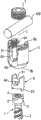
图1显示了根据第一实施例的多轴骨锚固装置的透视分解图。Fig. 1 shows a perspective exploded view of a polyaxial bone anchoring device according to a first embodiment.
图2显示了处于已组装状态的骨锚固装置的透视图。Figure 2 shows a perspective view of the bone anchoring device in an assembled state.
图3显示了处于已组装状态的多轴骨锚固装置的横截面图,该横截面在垂直于杆轴线的平面中获得。Figure 3 shows a cross-sectional view of the polyaxial bone anchoring device in the assembled state, the cross-section being taken in a plane perpendicular to the shaft axis.
图4显示了沿着图3中的线A-A的骨锚固装置的横截面图。Fig. 4 shows a cross-sectional view of the bone anchoring device along line A-A in Fig. 3 .
图5显示了处于已组装状态的骨装置的横截面图,该横截面在包括杆轴线的平面中获得。Figure 5 shows a cross-sectional view of the bone device in the assembled state, the cross-section being taken in a plane including the shaft axis.
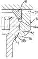
图6显示了图5的一部分的放大图。FIG. 6 shows an enlarged view of a portion of FIG. 5 .
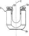
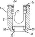
图7显示了多轴骨锚固装置的接收部件的透视图。Figure 7 shows a perspective view of a receiving part of a polyaxial bone anchoring device.
图8显示了图7的接收部件的侧视图。FIG. 8 shows a side view of the receiving part of FIG. 7 .
图9显示了接收部件的横截面图,该截面在包括杆轴线的平面中获得。Figure 9 shows a cross-sectional view of the receiving part, the section being taken in a plane including the rod axis.
图10显示了接收部件的横截面图,该截面在垂直于杆轴线的平面中获得。Figure 10 shows a cross-sectional view of the receiving part, the section being taken in a plane perpendicular to the shaft axis.
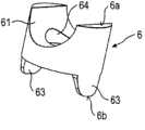
图11显示了压力元件的透视图。Figure 11 shows a perspective view of the pressure element.
图12显示了压力元件的侧视图。Figure 12 shows a side view of the pressure element.
图13显示了图12的压力元件转过90°的侧视图。Figure 13 shows a side view of the pressure element of Figure 12 turned by 90°.
图14显示了沿着图13中的线B-B的压力元件的横截面图。FIG. 14 shows a cross-sectional view of the pressure element along line B-B in FIG. 13 .
图15显示了图11的压力元件的仰视图。FIG. 15 shows a bottom view of the pressure element of FIG. 11 .
图16a)至16d)显示了组装多轴骨锚固装置的步骤。Figures 16a) to 16d) show the steps of assembling the polyaxial bone anchoring device.
图17显示了根据第二实施例的多轴骨锚固装置的横截面图,该截面在包括杆轴线的平面中获得。Fig. 17 shows a cross-sectional view of a polyaxial bone anchoring device according to a second embodiment, the section being taken in a plane including the shaft axis.
图18显示了根据第三实施例的多轴骨锚固装置的横截面图,该截面在包括杆轴线的平面中获得。Fig. 18 shows a cross-sectional view of a polyaxial bone anchoring device according to a third embodiment, the section being taken in a plane including the rod axis.
具体实施方式Detailed ways
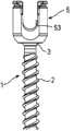
大体上在图1和2中显示的根据第一实施例的多轴骨锚固装置包括呈螺钉元件的形式的骨锚固元件1,所述骨锚固元件具有螺纹柄部2和头部3。头部3被成形为球节段,所述球节段具有包括球的赤道或最大直径E的尺寸。头部3在它的自由端上具有用于与工具接合的凹陷4。骨锚固装置还包括用于将螺钉元件1连接到杆100的接收部件5。压力元件6在接收部件中布置在头部3的顶部上。为了将杆100固定在接收部件中并且为了将压力施加于头部上,设有与接收部件5相配合的呈内螺钉7的形式的锁定装置。A polyaxial bone anchoring device according to a first embodiment generally shown in FIGS. 1 and 2 comprises a bone anchoring element 1 in the form of a screw element having a threaded
特别地如图3至10中所示,接收部件5为大致圆柱形并且具有顶端5a和底端5b以及朝着底端5b延伸的同轴腔孔51。在底端5b,设有用于容纳头部3的容座部分52。容座部分52为球形,具有的半径对应于头部3的半径,并且具有开口52b,柄部可以延伸通过所述开口。头部3允许在容座部分52中类似于球窝接头枢转。容座部分52的高度使得容座部分52包括头部3具有最大直径E的区域,如图6中所示。As shown in particular in Figures 3 to 10, the
在腔孔51和容座部分52之间设有中空圆柱形边缘部分52a,所述中空圆柱形边缘部分具有的内径小于腔孔51的内径并且仅仅略小于头部的最大外径E。换句话说,头部3相对于圆柱形边缘部分52a略微超尺寸以允许头部通过边缘部分被推入容座中。因此,一旦头部3被引入容座部分52中,它由圆柱形边缘部分52a保持在容座部分内。Between the
接收部件在顶端5a具有大致U形凹陷53,所述凹陷53形成用于接收杆100的通道。借助于U形凹陷形成垂直于接收部件5的中心轴线C延伸的通道轴线L。内螺纹54邻近顶端5a设在接收部件处以用于与锁定装置的内螺钉7相配合。The receiving part has a generally U-shaped
特别地在图7、9和10中可以看到,设有彼此偏移180°布置的两个凹陷55,所述凹陷从腔孔51延伸到离底端5b一定距离处进入容座部分52。凹陷55相对于通道轴线L成90°定位。凹陷55的形状被构造成容纳将在下面描述的压力元件6的一部分。It can be seen in particular in FIGS. 7 , 9 and 10 that there are two
压力元件6形成为单件。它为大致圆柱形构造并且具有的外径允许它在轴向方向上在接收部件5的腔孔51内移动。压力元件具有顶端6a和底端6b。在顶端6a设有圆柱形凹陷61,所述圆柱形凹陷被构造成在其中接收杆100。在底端6b设有用于在其中接收头部3的球形凹陷62。在底端6b设有在周向方向上的两个相对的切口,借助于所述切口设有两个向下延伸的相对凸耳63,所述凸耳的内表面为球形并且所述凸耳的外表面为圆柱形。在侧视图中看,凸耳63具有大致V形,例如如图13中所示,其中角部被圆整并且底部是直的。然而,凸耳的形状不限于实施例中所示的形状。例如,它可以为矩形或U形或其它形状。凸耳63相对于圆柱形凹陷所形成的通道轴线成90°布置。球形凹陷62的深度使得当压力元件安装到头部3上时凸耳63延伸超出球形头部3的具有最大外径E的区域。The
球形凹陷63相对于球形头部3的尺寸使得头部3相对于球形凹陷63略微超尺寸,使得当球形头部3插入球形凹陷63中时获得过盈配合,所述过盈配合通过由凸耳63施加于头部上的摩擦力保持头部。可以通过设计头部和具有凸耳63的球形凹陷62之间的适当过盈配合而调节摩擦力的强度。The dimensions of the
此外,压力元件6具有用于允许用工具(未显示)接近螺钉头部3的同轴腔孔64。Furthermore, the
骨锚固装置的所有部件由身体相容材料制造,所述生物相容材料例如为诸如钛的身体相容金属,诸如镍钛诺的身体相容合金,或诸如聚醚醚酮(PEEK)的身体相容塑料材料,或它们的组合。部件可以由相同或不同材料制造。All parts of the bone anchoring device are manufactured from body-compatible materials, such as body-compatible metals such as titanium, body-compatible alloys such as Nitinol, or body-compatible materials such as polyetheretherketone (PEEK). Compatible plastic materials, or combinations thereof. Components can be made from the same or different materials.
现在将参考图16a)至16d)描述骨锚固装置的组装。首先,如图16a)中所示,将骨锚固装置的头部3引入压力元件6的球形凹陷62中。由于头部3具有的直径略大于球形凹陷62的直径,因此头部3通过过盈配合保持在球形凹陷62内,如图16b)中所示。由此,凸耳63围绕头部延伸超出具有最大直径E的区域。在该状态下,可以通过施加力以克服头部和凸耳63之间的摩擦力而相对于压力元件6枢转头部。Assembly of the bone anchoring device will now be described with reference to Figures 16a) to 16d). First, as shown in FIG. 16 a ), the
然后,从顶端5a将安装有压力元件的螺钉元件1引入接收部件5中。由此,压力元件6被定向成使得它的圆柱形凹陷61与接收部件的U形凹陷12对准。所以,凸耳63被定向成使得它们可以接合接收部件的如先前图7中所示的凹陷55。最后,如图16d)中所示,通过克服插入通过容座部分的圆柱形上边缘52a和头部3之间的过盈配合插入的力而将头部3插入容座部分52中。Then, the screw element 1 fitted with the pressure element is introduced into the receiving
当带有压力元件6的头部3安装在接收部件5内时,头部3由凸耳63施加于头部上的摩擦力保持。此外,由于头部3由容座部分的圆柱形上边缘52a保持在容座部分52中,因此头部在可调节的角位置暂时保持在接收部件中。压力元件的附加固定(例如卷边)是非必要的,原因是压力元件通过凸耳63接合在凹陷55中而防止旋转并且通过与头部的过盈配合防止通过敞口顶端脱离,所述头部自身由上边缘52a保持在容座部分中。When the
在使用中,骨锚固装置可以在预组装状态下输送,如图16d)中所示。通常,需要若干骨锚固装置。然后将螺钉元件拧入骨或椎骨中并且然后对准接收部件以使杆100的插入具有正确取向。由于头部暂时被夹紧,因此为了枢转接收部件必须施加力以克服夹紧力直到每个接收部件具有正确取向。当所有接收部件对准时,插入连接骨锚固装置的杆并且上紧内螺钉7以向下移动压力元件,从而锁定头部使得螺钉元件相对于接收部件的角位置被固定。同时由内螺钉固定杆。In use, the bone anchoring device may be delivered in a pre-assembled state, as shown in Figure 16d). Typically, several bone anchoring devices are required. The screw element is then screwed into the bone or vertebrae and the receiving part is then aligned so that insertion of the
在图17中显示了多轴骨锚固装置的第二实施例。与先前实施例相同的所有部件用相同的附图标记指示并且不再重复它们的描述。根据第二实施例的多轴锚固装置与根据第一实施例的骨锚固装置的区别在于容座部分52的圆柱形边缘52a可以不存在。代替中空圆柱形边缘52a,接收部件在它的内壁中具有两个凹陷56,所述凹陷彼此偏移180°并且在通道轴线L的方向上定向。当头部3插入容座部分52中时凹陷的位置处于与头部3的最大直径E相比更靠近第二端部5b的位置。A second embodiment of a polyaxial bone anchoring device is shown in FIG. 17 . All components that are the same as those of the previous embodiment are denoted by the same reference numerals and their descriptions will not be repeated. The polyaxial anchoring device according to the second embodiment differs from the bone anchoring device according to the first embodiment in that the
压力元件包括两个附加凸耳64,所述附加凸耳延伸超出头部的具有最大直径E的区域并且均相对于凸耳63成90°定向。凸耳64的每一个具有向外延伸突出部65。当带有压力元件的螺钉元件插入接收部件中并且提供接收部件和压力元件之间的附加形状配合连接时突出部65卡扣到凹陷56中。凹陷相对于轴向方向具有这样的高度使得压力元件能够进一步向下移动以锁定头部3。The pressure element comprises two
在图18中显示了多轴骨锚固装置的第三实施例。根据第三实施例的多轴骨锚固装置与根据第二实施例的骨锚固装置的区别在于代替凹陷56和突出部65,凸耳64具有略微向外延伸的翼部66,所述翼部比接收部件的内径所允许的更向外延伸。当插入带有压力元件的头部时翼部66压靠在接收部件的内壁上并且通过压配合连接附加地保持头部。A third embodiment of a polyaxial bone anchoring device is shown in FIG. 18 . The polyaxial bone anchoring device according to the third embodiment differs from the bone anchoring device according to the second embodiment in that instead of the
先前所述的实施例的修改是可想到的。在第一修改中,头部3不是由边缘或由突出部或翼部保持在容座部分中。在这样的修改中,为了避免带有压力元件的头部在朝着顶端5a的方向上移动,压力元件通过卷边保持在接收部件内。Modifications of the previously described embodiments are conceivable. In a first modification, the
其它修改包括两个以上凸耳或其它形状的凸耳,如关于第一实施例所述。在另外的修改中,根据第一实施例的凸耳可以设在除了垂直于通道轴线以外的其它位置。而且,第二实施例的附加凸耳和突出部或第三实施例的翼部可以设在其它位置或以其它数量设置。Other modifications include more than two lugs or other shapes of lugs, as described with respect to the first embodiment. In further modifications, the lugs according to the first embodiment may be provided at other positions than perpendicular to the channel axis. Also, the additional lugs and protrusions of the second embodiment or the wings of the third embodiment may be provided in other positions or in other numbers.
容座部分可以具有除了球形以外的其它形状。例如,它可以为锥形。允许头部类似于球窝接头那样枢转的所有形状是可能的。而且头部和头部接触表面不必须为球形。它可以其它方式弯曲。The receptacle portion may have other shapes than spherical. For example, it can be tapered. All shapes that allow the head to pivot like a ball joint are possible. Also the head and the head contacting surface do not have to be spherical. It can be bent in other ways.
对于锚固元件,所有类型的锚固元件可以使用并且与接收部件组合。这些锚固元件例如是不同长度、具有不同直径的螺钉,插管螺钉、具有不同螺纹牙型的螺钉、钉等。头部和柄部可以是可连接到彼此的独立部件。For the anchoring element, all types of anchoring elements can be used and combined with the receiving part. These anchoring elements are, for example, screws of different lengths with different diameters, cannulated screws, screws with different thread profiles, nails and the like. The head and handle may be separate parts connectable to each other.
各种类型的接收部件可以特别地与不同的锁定装置一起使用。例如,代替单件式锁定装置,例如同时锁定杆和头部的内螺钉,可以使用具有外螺钉和内螺钉的两件式锁定装置。在该情况下,压力元件具有U形凹陷,所述U形凹陷具有延伸到杆之上的腿部。使用两件式锁定装置,可以单独地固定头部和杆。此外,外螺母、外帽、卡口锁定装置等也是可能的。接收部件的形状不限于所示的实施例。例如,接收部件可以具有不对称端部分以用于允许螺钉元件朝特定侧的更大枢转角。Various types of receiving parts can be used in particular with different locking devices. For example, instead of a one-piece locking device, such as an inner screw that locks both the stem and the head, a two-piece locking device with an outer screw and an inner screw could be used. In this case, the pressure element has a U-shaped recess with legs extending over the rod. Using the two-piece locking device, the head and stem can be secured separately. Furthermore, outer nuts, outer caps, bayonet locks etc. are also possible. The shape of the receiving part is not limited to the illustrated embodiment. For example, the receiving part may have an asymmetrical end portion for allowing a greater pivoting angle of the screw element towards a certain side.
在另一个修改中,接收部件被构造成允许从底端引入螺钉元件。In another modification, the receiving part is configured to allow introduction of the screw element from the bottom end.
Claims (15)
Applications Claiming Priority (4)
| Application Number | Priority Date | Filing Date | Title |
|---|---|---|---|
| US201061427412P | 2010-12-27 | 2010-12-27 | |
| EP10197083.8 | 2010-12-27 | ||
| EP10197083.8AEP2468199B1 (en) | 2010-12-27 | 2010-12-27 | Polyaxial bone anchoring device |
| US61/427,412 | 2010-12-27 |
Publications (2)
| Publication Number | Publication Date |
|---|---|
| CN102525622Atrue CN102525622A (en) | 2012-07-04 |
| CN102525622B CN102525622B (en) | 2016-04-20 |
Family
ID=44017758
Family Applications (1)
| Application Number | Title | Priority Date | Filing Date |
|---|---|---|---|
| CN201110431521.9AExpired - Fee RelatedCN102525622B (en) | 2010-12-27 | 2011-12-21 | Polyaxial bone anchoring device |
Country Status (7)
| Country | Link |
|---|---|
| US (2) | US9333011B2 (en) |
| EP (3) | EP2659845A1 (en) |
| JP (1) | JP6071193B2 (en) |
| KR (1) | KR20120074219A (en) |
| CN (1) | CN102525622B (en) |
| ES (2) | ES2433933T3 (en) |
| TW (1) | TW201228631A (en) |
Cited By (1)
| Publication number | Priority date | Publication date | Assignee | Title |
|---|---|---|---|---|
| CN112423684A (en)* | 2018-03-20 | 2021-02-26 | 美多斯国际有限公司 | Multi-point fixation implant |
Families Citing this family (25)
| Publication number | Priority date | Publication date | Assignee | Title |
|---|---|---|---|---|
| US9980753B2 (en) | 2009-06-15 | 2018-05-29 | Roger P Jackson | pivotal anchor with snap-in-place insert having rotation blocking extensions |
| US8444681B2 (en) | 2009-06-15 | 2013-05-21 | Roger P. Jackson | Polyaxial bone anchor with pop-on shank, friction fit retainer and winged insert |
| US8979904B2 (en) | 2007-05-01 | 2015-03-17 | Roger P Jackson | Connecting member with tensioned cord, low profile rigid sleeve and spacer with torsion control |
| US8007522B2 (en) | 2008-02-04 | 2011-08-30 | Depuy Spine, Inc. | Methods for correction of spinal deformities |
| CN103826560A (en) | 2009-06-15 | 2014-05-28 | 罗杰.P.杰克逊 | Polyaxial Bone Anchor with Socket Stem and Winged Inserts with Friction Fit Compression Collars |
| US9345519B1 (en)* | 2010-07-02 | 2016-05-24 | Presidio Surgical, Inc. | Pedicle screw |
| EP2606841B1 (en)* | 2011-12-23 | 2016-03-09 | Biedermann Technologies GmbH & Co. KG | Polyaxial bone anchoring device |
| US9782204B2 (en) | 2012-09-28 | 2017-10-10 | Medos International Sarl | Bone anchor assemblies |
| US9271761B2 (en) | 2012-12-11 | 2016-03-01 | Zimmer Spine | Bone anchoring device |
| EP2764840B1 (en)* | 2013-02-11 | 2017-05-03 | Biedermann Technologies GmbH & Co. KG | Coupling assembly for coupling a rod to a bone anchoring element and bone anchoring device with such a coupling assembly |
| US20140277153A1 (en) | 2013-03-14 | 2014-09-18 | DePuy Synthes Products, LLC | Bone Anchor Assemblies and Methods With Improved Locking |
| US9775660B2 (en) | 2013-03-14 | 2017-10-03 | DePuy Synthes Products, Inc. | Bottom-loading bone anchor assemblies and methods |
| US9724145B2 (en) | 2013-03-14 | 2017-08-08 | Medos International Sarl | Bone anchor assemblies with multiple component bottom loading bone anchors |
| US9259247B2 (en) | 2013-03-14 | 2016-02-16 | Medos International Sarl | Locking compression members for use with bone anchor assemblies and methods |
| US10342582B2 (en) | 2013-03-14 | 2019-07-09 | DePuy Synthes Products, Inc. | Bone anchor assemblies and methods with improved locking |
| ES2611014T3 (en) | 2014-01-13 | 2017-05-04 | Biedermann Technologies Gmbh & Co. Kg | Coupling assembly for coupling a rod to a bone anchoring element, and polyaxial bone anchoring device |
| CN108697445B (en) | 2016-02-26 | 2022-04-19 | 美多斯国际有限公司 | Polyaxial bone fixation element |
| US9962192B2 (en) | 2016-03-17 | 2018-05-08 | Medos International Sarl | Multipoint fixation implants |
| US11026730B2 (en) | 2017-05-10 | 2021-06-08 | Medos International Sarl | Bone anchors with drag features and related methods |
| US11571244B2 (en) | 2019-05-22 | 2023-02-07 | Nuvasive, Inc. | Posterior spinal fixation screws |
| EP4103083B1 (en) | 2020-02-14 | 2024-10-23 | Medos International Sàrl | Integrated multipoint fixation screw |
| USD956233S1 (en)* | 2020-04-24 | 2022-06-28 | Solco Biomedical Co., Ltd. | Cervical screw |
| CN111973324B (en)* | 2020-08-20 | 2022-11-11 | 四川大学华西医院 | Orthopedic implant system based on stress adaptive and controllable adjustment and its control method |
| US12364515B2 (en) | 2021-03-05 | 2025-07-22 | Medos International Sàrl | Multi-feature polyaxial screw |
| WO2022184797A1 (en) | 2021-03-05 | 2022-09-09 | Medos International Sarl | Selectively locking polyaxial screw |
Citations (6)
| Publication number | Priority date | Publication date | Assignee | Title |
|---|---|---|---|---|
| US20040267264A1 (en)* | 2003-06-27 | 2004-12-30 | Konieczynski David D. | Polyaxial bone screw |
| CN1965769A (en)* | 2005-10-12 | 2007-05-23 | 比德曼莫泰赫有限公司 | Bone anchoring device |
| WO2009014540A1 (en)* | 2007-07-26 | 2009-01-29 | Biotechni America Spine Group Inc. | Spinal fixation assembly |
| US20100145394A1 (en)* | 2008-11-03 | 2010-06-10 | Harvey Dustin M | Uni-planer bone fixation assembly |
| CN101810510A (en)* | 2009-02-20 | 2010-08-25 | 比德曼莫泰赫有限责任两合公司 | Bar linked the acceptance division of bone anchoring element and with the bone anchoring device of this acceptance division |
| CN101909536A (en)* | 2007-10-24 | 2010-12-08 | 纽瓦西弗公司 | Surgical fixation system and related methods |
Family Cites Families (27)
| Publication number | Priority date | Publication date | Assignee | Title |
|---|---|---|---|---|
| DE19507141B4 (en) | 1995-03-01 | 2004-12-23 | Harms, Jürgen, Prof. Dr.med. | Locking |
| US5879350A (en) | 1996-09-24 | 1999-03-09 | Sdgi Holdings, Inc. | Multi-axial bone screw assembly |
| US6010503A (en) | 1998-04-03 | 2000-01-04 | Spinal Innovations, Llc | Locking mechanism |
| US6113601A (en) | 1998-06-12 | 2000-09-05 | Bones Consulting, Llc | Polyaxial pedicle screw having a loosely coupled locking cap |
| DE19936286C2 (en) | 1999-08-02 | 2002-01-17 | Lutz Biedermann | bone screw |
| US6488681B2 (en) | 2001-01-05 | 2002-12-03 | Stryker Spine S.A. | Pedicle screw assembly |
| US8353932B2 (en) | 2005-09-30 | 2013-01-15 | Jackson Roger P | Polyaxial bone anchor assembly with one-piece closure, pressure insert and plastic elongate member |
| US6837889B2 (en) | 2002-03-01 | 2005-01-04 | Endius Incorporated | Apparatus for connecting a longitudinal member to a bone portion |
| US7066937B2 (en) | 2002-02-13 | 2006-06-27 | Endius Incorporated | Apparatus for connecting a longitudinal member to a bone portion |
| WO2005065397A2 (en) | 2003-12-30 | 2005-07-21 | Depuy Spine Sarl | Bone anchor assemblies |
| US7604655B2 (en) | 2004-10-25 | 2009-10-20 | X-Spine Systems, Inc. | Bone fixation system and method for using the same |
| US10076361B2 (en) | 2005-02-22 | 2018-09-18 | Roger P. Jackson | Polyaxial bone screw with spherical capture, compression and alignment and retention structures |
| US7811310B2 (en) | 2005-05-04 | 2010-10-12 | Spinefrontier, Inc | Multistage spinal fixation locking mechanism |
| WO2007041702A2 (en) | 2005-10-04 | 2007-04-12 | Alphaspine, Inc. | Pedicle screw system with provisional locking aspects |
| US20070118117A1 (en) | 2005-10-20 | 2007-05-24 | Ebi, L.P. | Bone fixation assembly |
| WO2008008511A2 (en) | 2006-07-14 | 2008-01-17 | Laszlo Garamszegi | Pedicle screw assembly with inclined surface seat |
| WO2008118295A2 (en) | 2007-03-26 | 2008-10-02 | Laszlo Garamszegi | Bottom-loading pedicle screw assembly |
| ES2348814T3 (en) | 2007-07-31 | 2010-12-15 | Biedermann Motech Gmbh | ANCHORAGE DEVICE Ã “SEO. |
| DE102007042953B4 (en)* | 2007-08-30 | 2015-01-22 | Aesculap Ag | Orthopedic retention system |
| ES2378588T3 (en) | 2008-12-30 | 2012-04-16 | Biedermann Motech Gmbh | Receiving part for receiving a rod for coupling the rod in a bone anchoring element and bone anchoring device with such receiving part |
| EP2548525B1 (en) | 2009-09-25 | 2014-04-02 | Biedermann Technologies GmbH & Co. KG | Bone anchoring device |
| ES2525046T3 (en) | 2009-12-21 | 2014-12-16 | Biedermann Technologies Gmbh & Co. Kg | Bone anchoring device |
| EP2606842B1 (en) | 2010-03-29 | 2018-08-29 | Biedermann Technologies GmbH & Co. KG | Bone anchoring device |
| EP3047812B1 (en) | 2010-11-22 | 2020-01-01 | Biedermann Technologies GmbH & Co. KG | Polyaxial bone anchoring device |
| US9044274B2 (en)* | 2010-12-01 | 2015-06-02 | Amendia, Inc. | Bone screw system |
| ES2461843T3 (en) | 2010-12-23 | 2014-05-21 | Biedermann Technologies Gmbh & Co. Kg | Bone anchoring device |
| EP2606841B1 (en) | 2011-12-23 | 2016-03-09 | Biedermann Technologies GmbH & Co. KG | Polyaxial bone anchoring device |
- 2010
- 2010-12-27EPEP13177920.9Apatent/EP2659845A1/ennot_activeWithdrawn
- 2010-12-27ESES10197083Tpatent/ES2433933T3/enactiveActive
- 2010-12-27EPEP10197083.8Apatent/EP2468199B1/enactiveActive
- 2010-12-27ESES13179464.6Tpatent/ES2614270T3/enactiveActive
- 2010-12-27EPEP13179464.6Apatent/EP2662038B1/enactiveActive
- 2011
- 2011-12-21TWTW100147588Apatent/TW201228631A/enunknown
- 2011-12-21KRKR1020110139132Apatent/KR20120074219A/ennot_activeCeased
- 2011-12-21CNCN201110431521.9Apatent/CN102525622B/ennot_activeExpired - Fee Related
- 2011-12-21JPJP2011279564Apatent/JP6071193B2/ennot_activeExpired - Fee Related
- 2011-12-27USUS13/338,188patent/US9333011B2/enactiveActive
- 2012
- 2012-09-14USUS13/618,000patent/US9585698B2/enactiveActive
Patent Citations (6)
| Publication number | Priority date | Publication date | Assignee | Title |
|---|---|---|---|---|
| US20040267264A1 (en)* | 2003-06-27 | 2004-12-30 | Konieczynski David D. | Polyaxial bone screw |
| CN1965769A (en)* | 2005-10-12 | 2007-05-23 | 比德曼莫泰赫有限公司 | Bone anchoring device |
| WO2009014540A1 (en)* | 2007-07-26 | 2009-01-29 | Biotechni America Spine Group Inc. | Spinal fixation assembly |
| CN101909536A (en)* | 2007-10-24 | 2010-12-08 | 纽瓦西弗公司 | Surgical fixation system and related methods |
| US20100145394A1 (en)* | 2008-11-03 | 2010-06-10 | Harvey Dustin M | Uni-planer bone fixation assembly |
| CN101810510A (en)* | 2009-02-20 | 2010-08-25 | 比德曼莫泰赫有限责任两合公司 | Bar linked the acceptance division of bone anchoring element and with the bone anchoring device of this acceptance division |
Cited By (1)
| Publication number | Priority date | Publication date | Assignee | Title |
|---|---|---|---|---|
| CN112423684A (en)* | 2018-03-20 | 2021-02-26 | 美多斯国际有限公司 | Multi-point fixation implant |
Also Published As
| Publication number | Publication date |
|---|---|
| JP2012135618A (en) | 2012-07-19 |
| EP2468199B1 (en) | 2013-08-07 |
| US20130066376A1 (en) | 2013-03-14 |
| EP2468199A1 (en) | 2012-06-27 |
| ES2614270T3 (en) | 2017-05-30 |
| KR20120074219A (en) | 2012-07-05 |
| US20120165882A1 (en) | 2012-06-28 |
| TW201228631A (en) | 2012-07-16 |
| EP2659845A1 (en) | 2013-11-06 |
| US9333011B2 (en) | 2016-05-10 |
| JP6071193B2 (en) | 2017-02-01 |
| ES2433933T3 (en) | 2013-12-13 |
| EP2662038B1 (en) | 2016-10-19 |
| EP2662038A1 (en) | 2013-11-13 |
| CN102525622B (en) | 2016-04-20 |
| US9585698B2 (en) | 2017-03-07 |
Similar Documents
| Publication | Publication Date | Title |
|---|---|---|
| CN102525622B (en) | Polyaxial bone anchoring device | |
| US20220031368A1 (en) | Bone anchoring device | |
| US10335204B2 (en) | Bone anchoring device | |
| US9924974B2 (en) | Polyaxial bone anchoring device | |
| JP6073597B2 (en) | Polyaxial bone anchoring device with an enlarged pivot angle | |
| US9192417B2 (en) | Monoplanar bone anchoring device with selectable pivot plane | |
| US9155568B2 (en) | Bone anchoring device | |
| JP6076648B2 (en) | Multiaxial bone anchoring system | |
| CN102100577B (en) | Bone anchoring device | |
| EP2687171A1 (en) | Polyaxial bone anchoring device | |
| US20130096622A1 (en) | Polyaxial bone anchoring device | |
| US20130110178A1 (en) | High angulation polyaxial bone anchoring device |
Legal Events
| Date | Code | Title | Description |
|---|---|---|---|
| C06 | Publication | ||
| PB01 | Publication | ||
| C10 | Entry into substantive examination | ||
| SE01 | Entry into force of request for substantive examination | ||
| C14 | Grant of patent or utility model | ||
| GR01 | Patent grant | ||
| CF01 | Termination of patent right due to non-payment of annual fee | Granted publication date:20160420 | |
| CF01 | Termination of patent right due to non-payment of annual fee |