CN102525335A - Robot cleaner - Google Patents
Robot cleanerDownload PDFInfo
- Publication number
- CN102525335A CN102525335ACN2011103496202ACN201110349620ACN102525335ACN 102525335 ACN102525335 ACN 102525335ACN 2011103496202 ACN2011103496202 ACN 2011103496202ACN 201110349620 ACN201110349620 ACN 201110349620ACN 102525335 ACN102525335 ACN 102525335A
- Authority
- CN
- China
- Prior art keywords
- shutter
- dust
- dust box
- opening
- robot cleaner
- Prior art date
- Legal status (The legal status is an assumption and is not a legal conclusion. Google has not performed a legal analysis and makes no representation as to the accuracy of the status listed.)
- Granted
Links
Images


Classifications
- A—HUMAN NECESSITIES
- A47—FURNITURE; DOMESTIC ARTICLES OR APPLIANCES; COFFEE MILLS; SPICE MILLS; SUCTION CLEANERS IN GENERAL
- A47L—DOMESTIC WASHING OR CLEANING; SUCTION CLEANERS IN GENERAL
- A47L11/00—Machines for cleaning floors, carpets, furniture, walls, or wall coverings
- A47L11/32—Carpet-sweepers
- A47L11/33—Carpet-sweepers having means for storing dirt
- A—HUMAN NECESSITIES
- A47—FURNITURE; DOMESTIC ARTICLES OR APPLIANCES; COFFEE MILLS; SPICE MILLS; SUCTION CLEANERS IN GENERAL
- A47L—DOMESTIC WASHING OR CLEANING; SUCTION CLEANERS IN GENERAL
- A47L11/00—Machines for cleaning floors, carpets, furniture, walls, or wall coverings
- A47L11/40—Parts or details of machines not provided for in groups A47L11/02 - A47L11/38, or not restricted to one of these groups, e.g. handles, arrangements of switches, skirts, buffers, levers
- A47L11/4013—Contaminants collecting devices, i.e. hoppers, tanks or the like
- A47L11/4025—Means for emptying
- A—HUMAN NECESSITIES
- A47—FURNITURE; DOMESTIC ARTICLES OR APPLIANCES; COFFEE MILLS; SPICE MILLS; SUCTION CLEANERS IN GENERAL
- A47L—DOMESTIC WASHING OR CLEANING; SUCTION CLEANERS IN GENERAL
- A47L11/00—Machines for cleaning floors, carpets, furniture, walls, or wall coverings
- A47L11/40—Parts or details of machines not provided for in groups A47L11/02 - A47L11/38, or not restricted to one of these groups, e.g. handles, arrangements of switches, skirts, buffers, levers
- A47L11/4072—Arrangement of castors or wheels
- A—HUMAN NECESSITIES
- A47—FURNITURE; DOMESTIC ARTICLES OR APPLIANCES; COFFEE MILLS; SPICE MILLS; SUCTION CLEANERS IN GENERAL
- A47L—DOMESTIC WASHING OR CLEANING; SUCTION CLEANERS IN GENERAL
- A47L9/00—Details or accessories of suction cleaners, e.g. mechanical means for controlling the suction or for effecting pulsating action; Storing devices specially adapted to suction cleaners or parts thereof; Carrying-vehicles specially adapted for suction cleaners
- A47L9/10—Filters; Dust separators; Dust removal; Automatic exchange of filters
- A47L9/14—Bags or the like; Rigid filtering receptacles; Attachment of, or closures for, bags or receptacles
- A47L9/1427—Means for mounting or attaching bags or filtering receptacles in suction cleaners; Adapters
- A47L9/1463—Means for mounting or attaching bags or filtering receptacles in suction cleaners; Adapters specially adapted for rigid filtering receptacles
- A—HUMAN NECESSITIES
- A47—FURNITURE; DOMESTIC ARTICLES OR APPLIANCES; COFFEE MILLS; SPICE MILLS; SUCTION CLEANERS IN GENERAL
- A47L—DOMESTIC WASHING OR CLEANING; SUCTION CLEANERS IN GENERAL
- A47L9/00—Details or accessories of suction cleaners, e.g. mechanical means for controlling the suction or for effecting pulsating action; Storing devices specially adapted to suction cleaners or parts thereof; Carrying-vehicles specially adapted for suction cleaners
- A47L9/10—Filters; Dust separators; Dust removal; Automatic exchange of filters
- A47L9/14—Bags or the like; Rigid filtering receptacles; Attachment of, or closures for, bags or receptacles
- A47L9/149—Emptying means; Reusable bags
- A—HUMAN NECESSITIES
- A47—FURNITURE; DOMESTIC ARTICLES OR APPLIANCES; COFFEE MILLS; SPICE MILLS; SUCTION CLEANERS IN GENERAL
- A47L—DOMESTIC WASHING OR CLEANING; SUCTION CLEANERS IN GENERAL
- A47L2201/00—Robotic cleaning machines, i.e. with automatic control of the travelling movement or the cleaning operation
- A47L2201/02—Docking stations; Docking operations
- A47L2201/024—Emptying dust or waste liquid containers
Landscapes
- Engineering & Computer Science (AREA)
- Mechanical Engineering (AREA)
- Electric Vacuum Cleaner (AREA)
- Filters For Electric Vacuum Cleaners (AREA)
- Manipulator (AREA)
Abstract
Translated fromChineseDescription
Translated fromChinese技术领域technical field
本公开的实施例涉及一种机器人吸尘器,该机器人吸尘器包括可分离地安装到主体的集尘箱,在独立地行进的同时执行清洁操作,并与自动排放站对接以自动地将灰尘从集尘箱排放到自动排放站。An embodiment of the present disclosure relates to a robot cleaner including a dust box detachably mounted to a main body, performing a cleaning operation while traveling independently, and docking with an automatic discharge station to automatically discharge dust from the dust collection Boxes are discharged to an automatic discharge station.
背景技术Background technique
机器人吸尘器包括各种传感器、驱动单元以及用于在机器人吸尘器独立地行进的同时执行清洁操作的清洁单元。The robot cleaner includes various sensors, a driving unit, and a cleaning unit for performing a cleaning operation while the robot cleaner travels independently.
通常,在这样的机器人吸尘器中,可分离的集尘箱被安装到机器人吸尘器的主体。因此,用户可在将集尘箱与主体分离之后将收集在集尘箱中的灰尘排出。然而,当分离的集尘箱摇晃或者翻转时,收集在集尘箱中的灰尘可能会被意外地排出。Generally, in such robot cleaners, a detachable dust box is mounted to the main body of the robot cleaner. Accordingly, the user may discharge the dust collected in the dust box after separating the dust box from the main body. However, when the separated dust box is shaken or turned over, the dust collected in the dust box may be accidentally discharged.
为此,会有必要提供这样一种结构,该结构允许集尘箱的入口在清洁操作期间打开,而在集尘箱与主体分离时使集尘箱的入口保持在关闭状态。For this reason, it may be necessary to provide a structure that allows an inlet of the dust box to be opened during a cleaning operation, and maintains the inlet of the dust box in a closed state when the dust box is separated from the main body.
同时,存在这样一种系统,该系统能够使机器人吸尘器与自动排放站对接,以自动地将灰尘从集尘箱排放到自动排放站。然而,在这样的系统中,难以将重的物品(包括硬币和其他重的颗粒)从集尘箱排出,这是因为重的物品可能会被形成在集尘箱的入口处的阶梯结构卡住。Meanwhile, there is a system capable of docking a robot cleaner with an automatic discharge station to automatically discharge dust from a dust box to the automatic discharge station. However, in such systems, it is difficult to discharge heavy items, including coins and other heavy particles, from the dust box because the heavy items may get caught by the stepped structure formed at the inlet of the dust box .
发明内容Contents of the invention
本公开的一方面在于提供一种机器人吸尘器,该机器人吸尘器具有开闭件结构(shutter structure),该开闭件结构用于防止收集在集尘箱中的灰尘意外地排出。An aspect of the present disclosure is to provide a robot cleaner having a shutter structure for preventing dust collected in a dust box from being accidentally discharged.
本公开的另一方面在于提供一种机器人吸尘器,该机器人吸尘器具有开闭件结构,当机器人吸尘器与自动排放站对接以自动地将灰尘从集尘箱排放到自动排放站时,该开闭件结构能够使重的灰尘容易排出。Another aspect of the present disclosure is to provide a robot cleaner having an opening and closing member structure that opens when the robot cleaner is docked with the automatic discharge station to automatically discharge dust from the dust box to the automatic discharge station. The structure enables easy discharge of heavy dust.
另外的方面和/或优点将在下面的描述中进行部分阐述,部分将通过描述而清楚,或者可通过本公开的实践而了解。Additional aspects and/or advantages will be set forth in part in the description which follows and in part will be obvious from the description, or may be learned by practice of the disclosure.
根据本公开的一方面,一种机器人吸尘器包括:主体;集尘箱,可分离地安装到所述主体,所述集尘箱包括集尘箱入口;第一开闭件,可旋转地结合到所述集尘箱;第二开闭件,可旋转地结合到所述集尘箱,以打开或者关闭所述集尘箱入口的一部分,其中,所述第一开闭件打开或者关闭所述集尘箱入口的剩余部分。According to an aspect of the present disclosure, a robot vacuum cleaner includes: a main body; a dust box detachably mounted to the main body, the dust box including a dust box inlet; a first opening and closing member rotatably coupled to the main body. the dust collecting box; a second opening and closing member rotatably coupled to the dust collecting box to open or close a part of the inlet of the dust collecting box, wherein the first opening and closing member opens or closes the The remainder of the dust bin inlet.
所述第一开闭件可包括开闭件旋转轴,该开闭件旋转轴布置在所述集尘箱入口处,同时沿所述集尘箱入口的纵向延伸。The first shutter may include a shutter rotation shaft arranged at the inlet of the dust box while extending in a longitudinal direction of the inlet of the dust box.
所述第一开闭件可被可枢转地结合到所述集尘箱的外侧表面,以竖直地旋转。The first shutter may be pivotally coupled to an outer side surface of the dust box to be vertically rotated.
当所述主体压迫所述第一开闭件时,所述第一开闭件可被打开。When the main body presses the first shutter, the first shutter may be opened.
当从所述主体施加到所述第一开闭件的压迫力被移除时,所述第一开闭件可通过重力而被关闭。The first shutter may be closed by gravity when the pressing force applied from the main body to the first shutter is removed.
所述机器人吸尘器还可包括使所述第一开闭件旋转的杆。The robot cleaner may further include a lever to rotate the first shutter.
所述主体可包括引导件,该引导件压迫所述杆,从而打开所述第一开闭件。The body may include a guide that presses the lever, thereby opening the first shutter.
所述引导件可形成有倾斜部,以使所述引导件逐渐压迫所述杆。The guide may be formed with a slope so that the guide gradually presses the rod.
所述机器人吸尘器还可包括磁体,该磁体被安装到所述第一开闭件,以使所述第一开闭件保持关闭。The robot cleaner may further include a magnet mounted to the first shutter to keep the first shutter closed.
刷清洁构件可被形成在所述第一开闭件的端部。A brush cleaning member may be formed at an end of the first shutter.
所述第二开闭件可包括开闭件旋转轴,该开闭件旋转轴布置在所述集尘箱入口处,同时沿所述集尘箱入口的纵向延伸。The second shutter may include a shutter rotation shaft disposed at the inlet of the dust box while extending in a longitudinal direction of the inlet of the dust box.
所述第二开闭件可在与所述集尘箱入口向内隔开预定距离的位置被可旋转地结合到所述主体。The second shutter may be rotatably coupled to the main body at a position spaced inwardly from the dust box inlet by a predetermined distance.
所述第二开闭件可通过被吹到所述第二开闭件的空气的压力而被打开。The second shutter may be opened by pressure of air blown to the second shutter.
当空气压力被移除时,所述第二开闭件可通过重力而被关闭。The second shutter may be closed by gravity when the air pressure is removed.
可通过从与所述主体对接的自动排放站排放的排放空气来产生空气压力。Air pressure may be generated by exhaust air exhausted from an automatic exhaust station docked with the body.
当所述第一开闭件被关闭时,可防止空气压力被施加到所述第二开闭件。When the first shutter is closed, air pressure may be prevented from being applied to the second shutter.
所述机器人吸尘器还可包括止动件,以限制所述第二开闭件的旋转范围。The robot cleaner may further include a stopper to limit a rotation range of the second opening and closing member.
所述机器人吸尘器还可包括磁体,该磁体被安装到所述第二开闭件,以使所述第二开闭件保持关闭。The robot cleaner may further include a magnet mounted to the second shutter to keep the second shutter closed.
根据本公开的另一方面,一种机器人吸尘器包括:主体;集尘箱,可分离地安装到所述主体,所述集尘箱包括集尘箱入口;第一开闭件,可旋转地结合到所述集尘箱,从而当所述集尘箱被安装到所述主体时,所述第一开闭件被打开,而当所述集尘箱与所述主体分离时,所述第一开闭件被关闭;第二开闭件,可旋转地结合到所述集尘箱,从而当灰尘从所述集尘箱被排放到自动排放站时,所述第二开闭件被打开,而当完成排放时,所述第二开闭件被关闭。According to another aspect of the present disclosure, a robot vacuum cleaner includes: a main body; a dust collecting box detachably mounted to the main body, the dust collecting box including a dust collecting box inlet; a first opening and closing member rotatably coupled to the main body; to the dust box, so that when the dust box is mounted to the main body, the first shutter is opened, and when the dust box is separated from the main body, the first the opening and closing member is closed; the second opening and closing member is rotatably coupled to the dust collecting box so that when the dust is discharged from the dust collecting box to the automatic discharge station, the second opening and closing member is opened, And when discharge is completed, the second shutter is closed.
根据本公开的另一方面,一种机器人吸尘器包括:主体;集尘箱,可分离地安装到所述主体,所述集尘箱包括集尘箱入口;开闭件,可旋转地结合到所述集尘箱,以打开或者关闭所述集尘箱入口;磁体,安装到所述开闭件,以使所述开闭件保持关闭。According to another aspect of the present disclosure, a robot cleaner includes: a main body; a dust box detachably mounted to the main body, the dust box including a dust box inlet; an opening and closing member rotatably coupled to the main body. The dust box is used to open or close the inlet of the dust box; a magnet is installed to the opening and closing member to keep the opening and closing member closed.
所述集尘箱可形成有防回流构件,以防止收集在所述集尘箱中的灰尘倒流。The dust box may be formed with a backflow prevention member to prevent dust collected in the dust box from backflow.
根据本公开的另一方面,一种机器人吸尘器包括:主体;集尘箱,可分离地安装到所述主体,所述集尘箱包括集尘箱入口;开闭件,可旋转地结合到所述集尘箱,以通过被吹到所述开闭件的空气的压力而旋转,从而打开或者关闭所述集尘箱入口。According to another aspect of the present disclosure, a robot cleaner includes: a main body; a dust box detachably mounted to the main body, the dust box including a dust box inlet; an opening and closing member rotatably coupled to the main body. The dust box is rotated by the pressure of the air blown to the opening and closing member, thereby opening or closing the dust box inlet.
所述开闭件可防止收集在所述集尘箱中的灰尘在所述开闭件关闭的状态下倒流。The opening and closing member can prevent the dust collected in the dust box from flowing back when the opening and closing member is closed.
根据本公开的又一方面,一种机器人吸尘器系统包括机器人吸尘器以及与该机器人吸尘器对接的自动排放站,其中,所述机器人吸尘器包括:主体;集尘箱,可分离地安装到所述主体,所述集尘箱包括集尘箱入口;开闭件,可旋转地结合到所述集尘箱,以通过被吹到所述开闭件的空气的压力而旋转,从而打开或者关闭所述集尘箱入口。According to still another aspect of the present disclosure, a robotic vacuum cleaner system includes a robotic vacuum cleaner and an automatic discharge station docked with the robotic vacuum cleaner, wherein the robotic vacuum cleaner includes: a main body; a dust collection box detachably mounted to the main body, The dust box includes a dust box inlet; an opening and closing member rotatably coupled to the dust collecting box to be rotated by the pressure of air blown to the opening and closing member, thereby opening or closing the collecting box. Dust box entrance.
所述自动排放站可包括排放管和吸入管。所述开闭件可通过从所述排放管的排放部排放的空气而旋转,来自所述集尘箱的灰尘通过朝着所述吸入管的吸入口被吸入的空气而被吸入到所述吸入管的所述吸入口中。The automatic discharge station may comprise a discharge pipe and a suction pipe. The shutter is rotatable by the air discharged from the discharge part of the discharge pipe, and the dust from the dust box is sucked into the suction port by the air sucked toward the suction port of the suction pipe. the suction port of the tube.
附图说明Description of drawings
通过下面结合附图对实施例进行的描述,本公开的这些和/或其他方面将会变得清楚和更加容易理解,在附图中:These and/or other aspects of the present disclosure will become clear and easier to understand through the following description of the embodiments in conjunction with the accompanying drawings, in which:
图1是示出根据本公开的示例性实施例的包括机器人吸尘器和自动排放站的机器人吸尘器系统的透视图;1 is a perspective view illustrating a robot cleaner system including a robot cleaner and an automatic discharge station according to an exemplary embodiment of the present disclosure;
图2是示出根据本公开的示例性实施例的机器人吸尘器的构造的剖视图;2 is a cross-sectional view illustrating a configuration of a robot cleaner according to an exemplary embodiment of the present disclosure;
图3是示出根据本公开示出的实施例的机器人吸尘器的底部视图;3 is a bottom view illustrating a robot cleaner according to an illustrated embodiment of the present disclosure;
图4是示出根据本公开的示例性实施例的自动排放站的构造的透视图;4 is a perspective view showing the configuration of an automatic discharge station according to an exemplary embodiment of the present disclosure;
图5是示出在图4中示出的自动排放站的构造的平面图;FIG. 5 is a plan view showing the configuration of the automatic discharge station shown in FIG. 4;
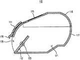
图6是示出根据本公开的示例性实施例的机器人吸尘器中的集尘箱在该集尘箱的第一开闭件和第二开闭件均被关闭的状态(即,集尘箱与主体分离的状态)下的构造的透视图;6 is a diagram illustrating a state in which the dust box of the robot cleaner according to an exemplary embodiment of the present disclosure is closed with both the first opening and closing member and the second opening and closing member (that is, the dust box and the second opening and closing member are closed). A perspective view of the structure in the state where the main body is separated);
图7是示出根据图6的实施例的集尘箱在第一开闭件被打开且第二开闭件被关闭的状态(即,集尘箱被安装到主体的状态)下的透视图;7 is a perspective view showing the dust box according to the embodiment of FIG. 6 in a state where the first shutter is opened and the second shutter is closed (ie, the state where the dust box is mounted to the main body) ;
图8是示出根据图6的实施例的集尘箱的第一开闭件和第二开闭件均被打开的状态(即,自动排放模式)的透视图;8 is a perspective view showing a state (ie, an automatic discharge mode) in which both the first shutter and the second shutter of the dust box according to the embodiment of FIG. 6 are opened;
图9是对应于图6的剖视图;Fig. 9 is a sectional view corresponding to Fig. 6;
图10是对应于图7的剖视图;Fig. 10 is a sectional view corresponding to Fig. 7;
图11是对应于图8的剖视图;Fig. 11 is a sectional view corresponding to Fig. 8;
图12是示出根据本公开的示例性实施例的杆和引导件在第一开闭件被关闭的状态下的视图,以解释杆和引导件的结构;12 is a view showing a lever and a guide in a state where a first shutter is closed according to an exemplary embodiment of the present disclosure, to explain structures of the lever and the guide;
图13是示出根据本公开示出的实施例的杆和引导件在第一开闭件被打开的状态下的视图,以解释杆和引导件的结构;13 is a view illustrating a lever and a guide according to an embodiment of the present disclosure in a state where a first shutter is opened to explain structures of the lever and the guide;
图14是示出包括在根据本公开的另一示例性实施例的机器人吸尘器中的集尘箱在该集尘箱的第一开闭件和第二开闭件均被关闭的状态(即,集尘箱与主体分离的状态)下的透视图;FIG. 14 is a diagram illustrating a state in which a dust box included in a robot cleaner according to another exemplary embodiment of the present disclosure has both its first and second opening and closing members closed (ie, A perspective view of a state where the dust box is separated from the main body);
图15是示出根据图14的实施例的集尘箱在第一开闭件被打开且第二开闭件被关闭的状态(即,集尘箱被安装到主体的状态)下的透视图;15 is a perspective view showing the dust box according to the embodiment of FIG. 14 in a state where the first shutter is opened and the second shutter is closed (ie, a state where the dust box is mounted to the main body) ;
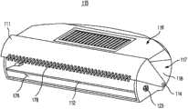
图16是示出根据图14的实施例的集尘箱在第一开闭件和第二开闭件均被打开的状态(即,自动排放状态)下的透视图;16 is a perspective view showing the dust box according to the embodiment of FIG. 14 in a state in which both the first shutter and the second shutter are opened (ie, an automatic discharge state);
图17是对应于图14的剖视图;Figure 17 is a sectional view corresponding to Figure 14;
图18是对应于图15的剖视图;Fig. 18 is a sectional view corresponding to Fig. 15;
图19是对应于图16的剖视图;Fig. 19 is a sectional view corresponding to Fig. 16;
图20是示出根据图14的实施例的集尘箱盖与集尘箱分离的状态的视图。FIG. 20 is a view showing a state where the dust box cover is separated from the dust box according to the embodiment of FIG. 14 .
具体实施方式Detailed ways
以下,将参照附图描述本公开的示例性实施例。Hereinafter, exemplary embodiments of the present disclosure will be described with reference to the accompanying drawings.
图1是示出根据本公开的示例性实施例的包括机器人吸尘器和自动排放站的机器人吸尘器系统的透视图。FIG. 1 is a perspective view illustrating a robot cleaner system including a robot cleaner and an automatic discharge station according to an exemplary embodiment of the present disclosure.
机器人吸尘器系统(由标号3表示)包括机器人吸尘器1以及可与机器人吸尘器1对接的自动排放站2。机器人吸尘器1包括主体4以及可分离地安装到主体4的集尘箱5。机器人吸尘器1利用安装到主体4的各种传感器33和驱动单元独立地行进,同时将积聚在地面上的灰尘收集到集尘箱5中,以清洁机器人吸尘器1周围的区域。The robot cleaner system (represented by reference numeral 3 ) includes a
图2是示出根据本公开的示例性实施例的机器人吸尘器的构造的剖视图。图3是示出根据本公开示出的实施例的机器人吸尘器的底部视图。FIG. 2 is a cross-sectional view illustrating a configuration of a robot cleaner according to an exemplary embodiment of the present disclosure. FIG. 3 is a bottom view illustrating the robot cleaner according to the illustrated embodiment of the present disclosure.
以下,将参照图1至图3描述根据本公开示出的实施例的机器人吸尘器的构造。在附图中,标号“F”表示机器人吸尘器1的前方向,标号“R”表示机器人吸尘器1的后方向。Hereinafter, a configuration of a robot cleaner according to an illustrated embodiment of the present disclosure will be described with reference to FIGS. 1 to 3 . In the drawings, symbol "F" denotes a front direction of the
如上所述,机器人吸尘器1包括主体4以及可分离地安装到主体4的集尘箱5。As described above, the
左驱动轮39a和右驱动轮39b以及脚轮38被安装到主体4,以使机器人吸尘器1能够行进。左驱动轮39a和右驱动轮39b被布置在主体4的底部上的中央区域,以使机器人吸尘器1能够向前或向后行进,或者改变机器人吸尘器1的行进方向。脚轮38被布置在主体4的底部上的前部区域,以使机器人吸尘器1能够保持稳定的姿势。Left and
刷单元35和侧刷34被安装在主体4上,以清洁主体4之下和主体4周围的地面区域。The
刷单元35被安装到穿过主体4的底部形成的第一开口41。刷单元35包括:滚轮36,可旋转地安装到主体4的第一开口41;刷37,由弹性材料制成并设置在滚轮36的外周表面。当滚轮36旋转时,刷37清扫地面上的灰尘。清扫的灰尘经由第一开口41被收集在集尘箱5中。The
侧刷34被可旋转地安装到主体4的底部的边缘部分(peripheral portion)的一侧,以使在主体4周围积聚的灰尘朝着刷单元35运动。即,侧刷34用于使机器人吸尘器1的清洁区扩大到主体4周围的区域。A
机器人吸尘器1还包括用于充电的连接端子40a和40b,以从自动排放站2接收电流。机器人吸尘器1还包括缓冲器32,缓冲器32被安装成吸收在机器人吸尘器1撞击障碍物时所产生的冲击。在机器人吸尘器1上还设置有显示器31,以提供各种信息。The
同时,集尘箱5被安装到主体4的后部。集尘箱5具有内部储存室,该内部储存室被分隔壁74分成第一储存室71和布置在第一储存室71之上的第二储存室72。第一储存室71形成有第一集尘箱入口76,第二储存室72形成有第二集尘箱入口77。Meanwhile, a
灰尘引导件79被布置在第一集尘箱入口76之下,以朝着第一集尘箱入口76引导由刷单元35清扫的灰尘。A
第二储存室72与设置在主体4中的鼓风单元80连通。刷单元35难以清扫的轻的灰尘在刷单元35旋转期间被向上分散,然后通过鼓风单元80的吸入力被收集在第二储存室72中。过滤器75被布置在第二储存室72与鼓风单元80之间,以防止收集在第二储存室72中的灰尘朝着鼓风单元80被吸入。The
刷清洁构件78被设置在第二集尘箱入口77处,以滤除缠绕并附着到刷单元35的杂质(例如,头发)。被刷清洁构件78滤除的杂质通过鼓风单元80的吸入力被收集在第二储存室72中。A
同时,第一开闭件11和第二开闭件12被安装到集尘箱5,以打开或者关闭第一集尘箱入口76。稍后将结合自动排放站来详细描述第一开闭件11和第二开闭件12。Meanwhile, the
图4是示出根据本公开的示例性实施例的自动排放站的构造的透视图。图5是示出在图4中示出的自动排放站的构造的平面图。FIG. 4 is a perspective view illustrating a configuration of an automatic discharge station according to an exemplary embodiment of the present disclosure. FIG. 5 is a plan view showing the configuration of the automatic discharge station shown in FIG. 4 .
参照图1至图5,自动排放站2适于使机器人吸尘器1与自动排放站2对接。当机器人吸尘器1与自动排放站2完全对接时,收集在集尘箱5中的灰尘被自动地排放到自动排放站2。自动排放站2还用于通过经充电端子52a和52b将电流供应到机器人吸尘器1而给机器人吸尘器1充电。Referring to FIGS. 1 to 5 , the
自动排放站2包括平台55以及形成在平台55的端部的外壳51。对接引导单元(未示出)、灰尘排放单元61以及控制器(未示出)被布置在外壳51内。The
平台55是平坦区域,机器人吸尘器1沿着该平坦区域运动。平台55具有倾斜结构,以允许机器人吸尘器1沿着平台55容易地上升或者从平台55下来。可在平台55上形成脚轮引导件53,以引导机器人吸尘器1的脚轮38。还可在平台55上形成驱动轮引导件54a和54b,以引导机器人吸尘器1的左驱动轮39a和右驱动轮39b。与平台55的在脚轮引导件53以及驱动轮引导件54a和54b附近的部分相比,脚轮引导件53以及驱动轮引导件54a和54b可被形成为凹下。The
第二开口56穿过平台55形成。平台55的第二开口56被布置在第二开口56可与机器人吸尘器1的第一开口41连通的位置。根据这种布置,通过机器人吸尘器1的第一开口41被排放的灰尘可被引入到平台55的第二开口56中。被引入到平台55的第二开口56中的灰尘可被收集在包括在自动排放站2中的集尘箱65中。A
同时,灰尘排放单元61被安装在外壳51中。灰尘排放单元61用于执行将收集在机器人吸尘器1的集尘箱5中的灰尘排放到自动排放站2的集尘箱65的功能。Meanwhile, a
灰尘排放单元61除包括集尘箱65之外还包括泵单元62、吸入管63以及排放管64a和64b。The
泵单元62是一种用于吸入/排放空气的装置。泵单元62包括风扇和电机。The
吸入管63被安装在泵单元62的吸入侧。吸入管63包括吸入口57,吸入口57形成第二开口56的一部分。A
排放管64a和64b被安装在泵单元62的排放侧。排放管64a包括排放口58a和59a,排放口58a和59a形成第二开口56的一部分。类似地,排放管64b包括排放口58b和59b,排放口58b和59b形成第二开口56的一部分。排放口58a、58b、59a和59b形成在第二开口56的纵向端部。排放口58a、58b、59a和59b被分成第一排放口58a和58b以及第二排放口59a和59b,第一排放口58a和58b从竖直方向向前倾斜期望的角度,第二排放口59a和59b从竖直方向向前倾斜比第一排放口58a和58b从竖直方向向前倾斜的角度小的角度。
排放口58a、58b、59a和59b的截面面积之和小于吸入口57的截面面积。因为泵单元62的吸入流量和排放流量基本上相等,所以由于排放口58a、58b、59a和59b与吸入口57之间的截面面积差而使得在排放口58a、58b、59a和59b处排放的空气E的流速高于在吸入口57处吸入的空气S的流速。由于这种流速差,因此可防止从排放口58a、58b、59a和59b出来的空气被直接吸入到吸入口57中。The sum of the cross-sectional areas of the
即,因为排放的空气E的气流速度很高,所以从排放口58a、58b、59a和59b出来的排放的空气E可被注入到与自动排放站2对接的机器人吸尘器1的集尘箱5的内部中,而不受吸入的空气S的影响。被注入到集尘箱5中的空气可在集尘箱5中循环之后被再次吸入到吸入口57中。That is, because the airflow velocity of the discharged air E is high, the discharged air E coming out from the
根据上述构造,在对接模式下通过灰尘排放单元61而进行循环的空气可形成闭合回路。即,从泵单元62排放的空气从排放管64a和64b的排放口58a、58b、59a和59b快速地出来,然后在经过第一开口41的相对两侧区域之后进入机器人吸尘器1的集尘箱5。被引入到机器人吸尘器1的集尘箱5中的空气在经过机器人吸尘器1的第一开口41的中央区域之后被引入到吸入口57中。随后,空气被吸入管63引导到自动排放站2的集尘箱65中。According to the above configuration, the air circulated through the
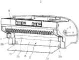
图6是示出根据本公开的示例性实施例的机器人吸尘器的集尘箱在该集尘箱的第一开闭件和第二开闭件均被关闭的状态(即,集尘箱与主体分离的状态)下的构造的透视图。6 is a diagram illustrating a state in which the first and second opening and closing members of the dust collecting box of the robot cleaner according to an exemplary embodiment of the present disclosure are closed (that is, the dust collecting box and the main body are closed). A perspective view of the structure in a detached state).
图7是示出根据本公开示出的实施例的集尘箱在第一开闭件被打开且第二开闭件被关闭的状态(即,集尘箱被安装到主体的状态)下的透视图。7 is a view showing the dust box in a state where the first shutter is opened and the second shutter is closed (that is, the state where the dust box is mounted to the main body) according to the embodiment shown in the present disclosure. perspective.
图8是示出根据本公开示出的实施例的集尘箱的第一开闭件和第二开闭件均被打开的状态(即,自动排放模式)的透视图。8 is a perspective view illustrating a state (ie, an automatic discharge mode) in which both the first shutter and the second shutter of the dust box according to the illustrated embodiment of the present disclosure are opened.
图9是对应于图6的剖视图,图10是对应于图7的剖视图,图11是对应于图8的剖视图。9 is a sectional view corresponding to FIG. 6 , FIG. 10 is a sectional view corresponding to FIG. 7 , and FIG. 11 is a sectional view corresponding to FIG. 8 .
以下,将参照图1至图11描述根据本公开的示例性实施例的集尘箱5的第一开闭件11和第二开闭件12的结构。Hereinafter, structures of the
如上所述,机器人吸尘器1的集尘箱5包括:第一储存室71,设置在集尘箱5的下部,用于收集重的灰尘;第二储存室72,设置在集尘箱5的上部,用于收集相对轻的灰尘。第一集尘箱入口76形成在第一储存室71处,第二集尘箱入口77形成在第二储存室72处。As mentioned above, the
集尘箱5可与主体4分离。因此,用户可在将集尘箱5与主体4分离之后将灰尘从第一储存室71和第二储存室72排出。The
同时,第一开闭件11和第二开闭件12被安装到集尘箱5,以打开或者关闭第一集尘箱入口76。Meanwhile, the
第二开闭件12被可旋转地结合到第一集尘箱入口76的中央部分。第二开闭件12包括沿第一集尘箱入口76的纵向延伸的旋转轴23。The
如图7中所示,第二开闭件12形成有开闭件开口27,从而即使在第二开闭件12被关闭的状态下也允许空气和灰尘穿过第二开闭件12。通过切割第二开闭件12的上部的中央部分来形成开闭件开口27。As shown in FIG. 7 , the
因此,即使在第二开闭件12被关闭的状态下也可通过开闭件开口27收集灰尘。因此,第二开闭件12用作防止收集在集尘箱5中的灰尘从集尘箱5排出的防回流构件。Therefore, dust can be collected through the shutter opening 27 even in a state where the
第二开闭件12具有上部25以及比上部25略重的下部26。根据这种结构,当没有对第二开闭件12施加外力时,下部26被向下引导并且上部25由于重力而被向上引导,以使第一集尘箱入口76自然关闭。The
当然,当集尘箱5倾斜或摇晃时,第二开闭件12会摆动。为此,动磁体28a和28b分别被安装到第二开闭件12的下部26的相对两表面,以使第二开闭件12保持密封。Of course, when the
固定磁体28c和28d在与动磁体28a和28b对应的位置被安装到集尘箱5的内表面。由于动磁体28a和28b与固定磁体28c和28d之间的磁引力,因此第二开闭件12保持关闭。The fixed
动磁体28a和28b可被布置在第二开闭件12的前表面,以防止由于动磁体28a和28b与固定磁体28c和28d之间的直接接触而导致磁引力过度增加。The moving
动磁体28a和28b以及固定磁体28c和28d可以是铌磁体。这样的铌磁体适合于根据本公开示出的实施例的机器人吸尘器1,这是因为它们的机械强度高,从而减少破损,同时它们的比重低,从而实现小型化和轻量化。The moving
如上所述,第二开闭件12通过重力而被关闭,同时通过从自动排放站2排出的第一排放空气E1而被打开。As described above, the
如图8和图11所示,当从自动排放站2排出的第一排放空气E1的压力被施加到第二开闭件12的上部25时,第二开闭件12旋转,使得第二开闭件12的上部25被插入到集尘箱5中,并且第二开闭件12的下部26从集尘箱5向外突出。因此,第一集尘箱入口76被打开。8 and 11, when the pressure of the first discharge air E1 discharged from the
具体地讲,由于第二开闭件12旋转使得第二开闭件12的下部26从集尘箱5向外突出,因此可防止收集在第一储存室71中的灰尘被向内推动到第一储存室71中或者被卡在第二开闭件12与集尘箱5的内表面之间。Specifically, since the
当第二开闭件12被打开时,即使是收集在第一储存室71中的重的灰尘也可通过第一集尘箱入口76的下部从集尘箱5被容易地排出。When the
由于磁引力被施加在相应的动磁体28a和28b与相应的固定磁体28c和28d之间以使第二开闭件12保持关闭,因此第一排放空气E1的强度应当大于被施加在相应的动磁体28a和28b与相应的固定磁体28c和28d之间的磁引力的和。Since the magnetic attraction force is applied between the corresponding moving
为了使第二开闭件12大约停止在旋转90°的位置,多个止动件29被设置在集尘箱5中,以在第二开闭件12旋转时支撑第二开闭件12的上部25。止动件29具有从集尘箱5的内底表面向上延伸一定长度的杆结构。止动件29彼此隔开一定距离,以免妨碍灰尘的排放。In order to stop the second opening and closing
因此,当第一排放空气E1被施加到第二开闭件12时,第二开闭件12在旋转到其与止动件29接触的位置(在该位置,第二开闭件12大致水平地布置)之后停止,而不继续旋转。Therefore, when the first discharge air E1 is applied to the
以下,将描述如上所述的第二开闭件12与自动排放站2之间的关系。Hereinafter, the relationship between the
机器人吸尘器1和自动排放站2被构造成使得当机器人吸尘器1与自动排放站2对接时,通过自动排放站2的第一排放口58a和58b被排放的第一排放空气E1被引导到第二开闭件12的上部25,而通过第二排放口59a和59b被排放的第二排放空气E2被引导到集尘箱5的第二储存室72。The
当通过第一排放口58a和58b被排放的第一排放空气E1被施加到第二开闭件12的上部25时,第二开闭件12旋转,从而打开第一集尘箱入口76。此时,收集在第一储存室71中的灰尘通过被引导到自动排放站2的吸入口57的吸入空气S被吸入到自动排放站2中。When the first discharge air E1 discharged through the
被引导到第二储存室72的第二排放空气E2使收集在第二储存室72中的轻的灰尘向上浮动。浮动的灰尘也通过吸入空气S被吸入到自动排放站2中。The second discharge air E2 guided to the
同时,除如上所述的第二开闭件12之外,第一开闭件11被设置在集尘箱5处,以打开或者关闭第一集尘箱入口76。Meanwhile, in addition to the
第一开闭件11具有能够打开或者关闭第二开闭件12的开闭件开口27的尺寸。第一开闭件11包括旋转轴14,旋转轴14布置在第一集尘箱入口76的上端,同时沿第一集尘箱入口76的纵向延伸。The
第一开闭件11的一端结合到旋转轴14。当第一开闭件11被关闭时,第一开闭件11的另一端与第一集尘箱入口76的下端接触以使开闭件开口27关闭。One end of the
因此,第一开闭件11被可枢转地结合到第一集尘箱入口76的上端,使得第一开闭件11向第一储存室71外枢转,从而被打开。因此,即使当收集在第一储存室71中的灰尘的量大时,第一开闭件11的打开操作也不会被灰尘阻碍。Therefore, the
同时,杆13与第一开闭件11一体地形成,以使第一开闭件11枢转。Meanwhile, a
杆13分别被布置在旋转轴14的轴向两端,同时基本上呈弧形。因为杆13与第一开闭件11是一体的,所以当杆13通过外力而旋转时,第一开闭件11旋转。The
当没有对杆13施加外力时,第一开闭件11通过重力而使第一集尘箱入口76关闭。When no external force is applied to the
与第二开闭件12类似,动磁体15a和15b被安装到第一开闭件11的前表面,以使第一开闭件11保持关闭。Similar to the
固定磁体15c分别在与动磁体15a和15b对应的位置被安装到第二开闭件12的后表面,以在动磁体15a和15b与固定磁体15c之间产生磁引力(在附图中,仅示出了一个固定磁体15c)。
动磁体15a和15b可被布置在第一开闭件11的前表面的相对两侧并且固定磁体15c可被布置在第二开闭件12的后表面的相对两侧,以防止磁引力过度增加。The moving
与利用弹簧的弹力的系统相比,利用如上所述的磁体的磁引力的系统的有效之处在于其构造简单且不存在灰尘被卡在系统中的可能性。Compared with the system using the elastic force of the spring, the system using the magnetic attraction force of the magnet as described above is effective in that it is simple in construction and there is no possibility of dust being caught in the system.
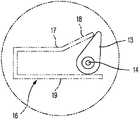
图12是示出根据本公开的示例性实施例的一个杆和引导件在第一开闭件被关闭的状态下的视图,以解释杆和引导件的结构。FIG. 12 is a view showing one lever and guide in a state in which a first shutter is closed to explain structures of the lever and guide according to an exemplary embodiment of the present disclosure.
图13是示出根据本公开示出的实施例的杆和引导件在第一开闭件被打开的状态下的视图,以解释杆和引导件的结构。FIG. 13 is a view illustrating a lever and a guide according to an embodiment of the present disclosure in a state where a first shutter is opened to explain structures of the lever and the guide.
引导件16分别在与集尘箱5的杆13对应的位置形成在主体4的内表面上,以压迫杆13。
如图12和图13所示,每个引导件16包括:支承部19,用于引导并支承相应的杆13;推动部17,用于压迫杆13。As shown in FIGS. 12 and 13 , each
在将集尘箱5安装到主体4的过程期间,集尘箱5的杆13分别被相应的推动部17压迫,以围绕旋转轴14旋转。此时,与杆13一体的第一开闭件11枢转,从而打开第一集尘箱入口76。During the process of installing the
相反,当集尘箱5与主体4分离时,由推动部17施加到杆13的外力被释放。因此,第一开闭件11通过重力而沿相反的方向旋转,从而关闭第一集尘箱入口76。On the contrary, when the
同时,每个引导件16还包括倾斜部18,倾斜部18从引导件16的推动部17倾斜地延伸。倾斜部18允许推动部17逐渐压迫相应的杆13,而不是瞬间压迫相应的杆13。Meanwhile, each guide 16 also includes an
当集尘箱5接近主体4时,每个杆13首先与相应的倾斜部18的上端接触,使得杆13开始旋转。随着集尘箱5进一步接近主体4,杆13被倾斜部18的中央部分压迫,使得杆13进一步旋转。当集尘箱5完全接近主体4时,杆13被倾斜部18的下部压迫,使得杆13旋转大约90°的角度。When the
由于每个杆13通过相应的倾斜部18逐渐旋转而不是瞬间旋转,因此施加到第一开闭件11或集尘箱5的冲击被减轻,从而可防止收集在集尘箱5中的灰尘被分散。Since each
将集尘箱5与主体4分离的过程与将集尘箱5安装到主体4的过程相反。The process of separating the
在此之前,已经描述了根据本公开示出的实施例的机器人吸尘器1的构造。以下,将简要描述根据本公开的示例性实施例的机器人吸尘器1的操作。Heretofore, the configuration of the
在集尘箱5与主体4分离的状态下,灰尘不会从集尘箱5向外排出,这是因为第一开闭件11和第二开闭件12均被关闭(如图6和图9所示)。由于第一开闭件11和第二开闭件12通过磁引力而保持关闭,因此即使在集尘箱5略微摆动时也保持第一开闭件11和第二开闭件12的关闭状态。In the state where the
当将集尘箱5安装到主体4时,形成在主体4的内表面上的引导件16压迫各个杆13(如图7和图10所示)。因此,第一开闭件11在围绕旋转轴14向前旋转的同时被打开。在这种情况下,第二开闭件12保持关闭。因此,第一集尘箱入口76仅通过第二开闭件12而被保持关闭。由于开闭件开口27形成在第二开闭件12的上部中央部分,因此可经由开闭件开口27将灰尘收集到第一储存室71中。在这种情况下,第二开闭件12用作防止收集在第一储存室71中的灰尘倒流的防回流构件。When the
当在上述状态下开始机器人吸尘器1的清洁模式时,刷单元35清扫积聚在地面上的灰尘并将清扫的灰尘收集到第一储存室71中。可能难以清扫的轻的灰尘通过鼓风单元80的吸入力被收集在第二储存室72中。When the cleaning mode of the
当安装有集尘箱5的机器人吸尘器1随后与自动排放站2对接以开始自动排放模式时,第一排放空气E1经由自动排放站2的第一排放口58a和58b被吹向第二开闭件12的上部25,第二排放空气E2经由自动排放站2的第二排放口59a和59b被吹向第二储存室72(如图8和图11所示)。另外,存在于第一储存室71和第二储存室72中的空气朝着自动排放站2的吸入口57被吸入。When the
因此,第二开闭件12通过经由自动排放站2的第一排放口58a和58b被吹动的第一排放空气E1而旋转,使得第二开闭件12的上部25被引导到集尘箱5的内部,并且第二开闭件12的下部26被引导到集尘箱5的外部。此时,随着第二开闭件12与设置在集尘箱5处的止动件29接触,第二开闭件12在旋转大约90°的角度时被打开。Therefore, the
同时,收集在第二储存室72中的灰尘通过经由自动排放站2的第二排放口59a和59b被吹动的第二排放空气E2而被向上提升。Meanwhile, the dust collected in the
此时,自动排放站2吸入空气,以向外排放收集在第一储存室71和第二储存室72中的灰尘。具体地讲,即使是收集在第一储存室71中的重的灰尘也可被容易地排出,这是因为关闭第一集尘箱入口76的下部的第二开闭件12被打开。At this time, the
在此之前,已经描述了根据本公开的一个示例性实施例的机器人吸尘器。以下,将描述根据本公开的另一示例性实施例的机器人吸尘器。Heretofore, the robot cleaner according to an exemplary embodiment of the present disclosure has been described. Hereinafter, a robot cleaner according to another exemplary embodiment of the present disclosure will be described.
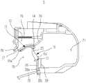
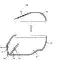
图14是示出包括在根据本公开的另一示例性实施例的机器人吸尘器中的集尘箱在该集尘箱的第一开闭件和第二开闭件均被关闭的状态(即,集尘箱与主体分离的状态)下的透视图。FIG. 14 is a diagram illustrating a state in which a dust box included in a robot cleaner according to another exemplary embodiment of the present disclosure has both its first and second opening and closing members closed (ie, Perspective view of the state where the dust box is separated from the main body).
图15是示出根据图14的实施例的集尘箱在第一开闭件被打开且第二开闭件被关闭的状态(即,集尘箱被安装到主体的状态)下的透视图。15 is a perspective view showing the dust box according to the embodiment of FIG. 14 in a state where the first shutter is opened and the second shutter is closed (ie, a state where the dust box is mounted to the main body) .
图16是示出根据图14的实施例的集尘箱在第一开闭件和第二开闭件均被打开的状态(即,自动排放状态)下的透视图。16 is a perspective view showing the dust box according to the embodiment of FIG. 14 in a state in which both the first shutter and the second shutter are opened (ie, an automatic discharge state).
图17是对应于图14的剖视图,图18是对应于图15的剖视图,图19是对应于图16的剖视图。17 is a sectional view corresponding to FIG. 14 , FIG. 18 is a sectional view corresponding to FIG. 15 , and FIG. 19 is a sectional view corresponding to FIG. 16 .
上述组成部件中的一部分也被应用于根据本实施例的机器人吸尘器,因此,将不再给出对这些部件的描述。在下面的描述中,将仅描述该实施例与上述实施例的不同之处。Some of the above-described constituent components are also applied to the robot cleaner according to the present embodiment, and therefore, no description will be given of these components. In the following description, only the differences of this embodiment from the above-mentioned embodiments will be described.
根据该实施例的集尘箱(由标号115表示)包括集尘箱主体117以及可分离地安装到集尘箱主体117的集尘箱盖116。集尘箱盖116与集尘箱主体117一起限定集尘箱115的外观。储存空间171限定在集尘箱主体117中。过滤器175被安装到集尘箱盖116,以防止收集在集尘箱115中的灰尘被吸入到机器人吸尘器的主体中。The dust box (denoted by reference numeral 115 ) according to this embodiment includes a
集尘箱入口176形成在集尘箱主体117的前侧,以允许灰尘被引入到储存空间171中或者从储存空间171排出。第一开闭件111和第二开闭件112也被设置在集尘箱主体117处,以打开或者关闭集尘箱入口176。A
如图14中所示,第一开闭件111被构造成完全打开或者关闭集尘箱入口176。即,当第一开闭件111被关闭时,第一开闭件111的下端与集尘箱入口176的下端接触。As shown in FIG. 14 , the
第一开闭件111通过铰接构件114被可枢转地结合到集尘箱主体117的外侧表面118,以竖直地枢转。即,第一开闭件111沿着集尘箱115的外表面执行枢转运动,而不进入集尘箱115的储存空间171。因此,不存在收集在储存空间171中的灰尘被卡在第一开闭件111与集尘箱115的壁之间的现象。另外,集尘箱115具有简单的结构。The
同时,刷清洁构件178形成在第一开闭件111的下端。刷清洁构件178具有耙子形状,以滤除杂质。Meanwhile, a
第二开闭件112包括旋转轴123,旋转轴123在与集尘箱入口176向内隔开一定距离的位置被可旋转地安装到集尘箱主体117。第二开闭件112在被完全关闭时倾斜地定位。因此,即使在第二开闭件112被完全关闭时灰尘也可被收集在集尘箱115中。The
第二开闭件112通过来自自动排放站2的第一排放空气E1(图4)而围绕旋转轴123旋转,使得第二开闭件112被打开。The
图20是示出根据图14的实施例的集尘箱盖与集尘箱分离的状态的视图。FIG. 20 is a view showing a state where the dust box cover is separated from the dust box according to the embodiment of FIG. 14 .
如上所述,集尘箱115包括:集尘箱主体¨7,被构造成允许用户容易地从集尘箱主体117直接排放灰尘;集尘箱盖116,可分离地安装到集尘箱主体117。用户可在将集尘箱盖116与集尘箱主体117分离之后将灰尘容易地排出。As described above, the
从以上描述清楚的是,本公开的特征在于包括:第一开闭件,用于在将集尘箱与机器人吸尘器的主体分离时防止灰尘从集尘箱意外地排出;第二开闭件,在机器人吸尘器与自动排放站对接时所执行的自动排放模式下,第二开闭件通过从自动排放站吹动的排放空气而被自动地打开,从而即使是收集在集尘箱中的重的灰尘也会被容易地排出。As apparent from the above description, the present disclosure is characterized by including: a first opening and closing member for preventing dust from being accidentally discharged from the dust collecting box when the dust collecting box is separated from the main body of the robot cleaner; a second opening and closing member, In the automatic discharge mode performed when the robot cleaner is docked with the automatic discharge station, the second shutter is automatically opened by the discharge air blown from the automatic discharge station, so that even heavy dust collected in the dust box Dust is also easily discharged.
当集尘箱被安装到机器人吸尘器的主体时,第一开闭件(用作防止灰尘意外排放的开闭件)打开集尘箱的入口,当集尘箱与主体分离时,第一开闭件关闭集尘箱的入口。因此,第一开闭件防止灰尘从集尘箱意外地排出。When the dust box is attached to the main body of the robot cleaner, the first opening and closing member (used as an opening and closing member to prevent accidental discharge of dust) opens the inlet of the dust box, and when the dust box is separated from the main body, the first opening and closing parts to close the inlet to the dust box. Therefore, the first shutter prevents dust from being accidentally discharged from the dust box.
此外,第一开闭件通过磁引力而被保持关闭,从而即使在集尘箱摇晃或者翻转时也防止第一开闭件被容易地打开。In addition, the first shutter is kept closed by magnetic attraction, thereby preventing the first shutter from being easily opened even when the dust box is shaken or turned over.
同时,当机器人吸尘器在与自动排放站对接之后从集尘箱排放灰尘时,第二开闭件(用作防回流构件或自动排放开闭件)被自动地打开。因此,即使是收集在集尘箱中的重的灰尘也可被容易地排出。Meanwhile, when the robot cleaner discharges dust from the dust box after being docked with the automatic discharge station, the second shutter (serving as the backflow prevention member or the automatic discharge shutter) is automatically opened. Therefore, even heavy dust collected in the dust box can be easily discharged.
虽然已经示出并描述了本公开的一些实施例,但是本领域技术人员应该理解,在不脱离由权利要求及其等同物限定其范围的本公开的原理和精神的情况下,可以对这些实施例进行改变。While certain embodiments of the present disclosure have been shown and described, it will be understood by those skilled in the art that such implementations may be made without departing from the principles and spirit of the present disclosure, the scope of which is defined by the claims and their equivalents. Example changes.
Claims (14)
Translated fromChineseApplications Claiming Priority (2)
| Application Number | Priority Date | Filing Date | Title |
|---|---|---|---|
| KR1020100108480AKR101496913B1 (en) | 2010-11-03 | 2010-11-03 | Robot cleaner, automatic exhaust station and robot cleaner system having the same |
| KR10-2010-0108480 | 2010-11-03 |
Publications (2)
| Publication Number | Publication Date |
|---|---|
| CN102525335Atrue CN102525335A (en) | 2012-07-04 |
| CN102525335B CN102525335B (en) | 2016-01-20 |
Family
ID=44999672
Family Applications (1)
| Application Number | Title | Priority Date | Filing Date |
|---|---|---|---|
| CN201110349620.2AExpired - Fee RelatedCN102525335B (en) | 2010-11-03 | 2011-10-31 | Robot cleaner |
Country Status (4)
| Country | Link |
|---|---|
| US (2) | US9060666B2 (en) |
| EP (1) | EP2449939B1 (en) |
| KR (1) | KR101496913B1 (en) |
| CN (1) | CN102525335B (en) |
Cited By (19)
| Publication number | Priority date | Publication date | Assignee | Title |
|---|---|---|---|---|
| CN106659346A (en)* | 2014-07-04 | 2017-05-10 | 东芝生活电器株式会社 | Electric vacuum cleaner |
| CN107595207A (en)* | 2014-12-10 | 2018-01-19 | 美国iRobot公司 | Chip evacuation for clean robot |
| CN107997685A (en)* | 2016-10-28 | 2018-05-08 | 美国iRobot公司 | Mobile clean robot with case |
| CN108784520A (en)* | 2018-06-27 | 2018-11-13 | 杨扬 | The method that band embeds the dust-collecting robot of dirt box and establishes grating map |
| CN110403512A (en)* | 2018-04-26 | 2019-11-05 | 日立环球生活方案株式会社 | electric vacuum cleaner |
| CN110466918A (en)* | 2019-08-21 | 2019-11-19 | 深圳市无限动力发展有限公司 | Garbage reclamation station and cleaning systems |
| CN110604512A (en)* | 2019-08-21 | 2019-12-24 | 深圳市无限动力发展有限公司 | Cleaning equipment, cleaning machine and dust collecting box thereof |
| CN110604513A (en)* | 2019-08-21 | 2019-12-24 | 深圳市无限动力发展有限公司 | Cleaning machine and cleaning system |
| CN110946517A (en)* | 2018-09-27 | 2020-04-03 | 欧姆龙株式会社 | Autonomous driving type cleaning device |
| CN112120590A (en)* | 2020-09-29 | 2020-12-25 | 苏州云森科技有限公司 | Floor cleaner with multifunctional dust box cover |
| CN113171027A (en)* | 2021-04-02 | 2021-07-27 | 美智纵横科技有限责任公司 | Cleaning device, dust box assembly, control method and control system |
| US11076730B2 (en) | 2017-12-04 | 2021-08-03 | Samsung Electronics Co., Ltd. | Robot cleaner |
| CN113576334A (en)* | 2021-08-12 | 2021-11-02 | 广东旺家智能机器人有限公司 | Sweeping robot with collecting station |
| WO2022095940A1 (en)* | 2020-11-06 | 2022-05-12 | 追觅创新科技(苏州)有限公司 | Maintenance station, automatic cleaning system, central workstation and intelligent cleaning system |
| CN114642381A (en)* | 2022-02-23 | 2022-06-21 | 上海岚豹智能科技有限公司 | Intelligent floor sweeping robot |
| CN114680743A (en)* | 2020-12-31 | 2022-07-01 | 深圳银星智能集团股份有限公司 | Dust box assembly, cleaning robot and system thereof |
| CN114903382A (en)* | 2022-06-02 | 2022-08-16 | 深圳市云视机器人有限公司 | Dust boxes, floor cleaning equipment and systems |
| CN115778235A (en)* | 2019-09-05 | 2023-03-14 | 三星电子株式会社 | Cleaning apparatus with vacuum cleaner and docking station and method of controlling the same |
| WO2024216567A1 (en)* | 2023-04-20 | 2024-10-24 | Sharkninja Operating Llc | Vacuum cleaner |
Families Citing this family (81)
| Publication number | Priority date | Publication date | Assignee | Title |
|---|---|---|---|---|
| KR101494231B1 (en) | 2007-01-23 | 2015-02-17 | 쎄라피콘 에스.알.엘. | Antiviral compound |
| IT1396620B1 (en) | 2009-11-25 | 2012-12-14 | Therapicon Srl | CHEMICAL ANALOGUES |
| KR101496913B1 (en)* | 2010-11-03 | 2015-03-02 | 삼성전자 주식회사 | Robot cleaner, automatic exhaust station and robot cleaner system having the same |
| KR101198522B1 (en)* | 2010-12-21 | 2012-11-06 | 엘지전자 주식회사 | Vacuum cleaner |
| USD682495S1 (en)* | 2011-11-03 | 2013-05-14 | Samsung Electronics Co., Ltd. | Vacuum cleaner |
| ES2610755T3 (en) | 2012-08-27 | 2017-05-03 | Aktiebolaget Electrolux | Robot positioning system |
| US9757160B2 (en) | 2012-09-28 | 2017-09-12 | Globus Medical, Inc. | Device and method for treatment of spinal deformity |
| US10703589B2 (en)* | 2012-12-22 | 2020-07-07 | Maytronics Ltd. | Dry docking station |
| WO2014169943A1 (en) | 2013-04-15 | 2014-10-23 | Aktiebolaget Electrolux | Robotic vacuum cleaner |
| KR102137923B1 (en) | 2013-04-15 | 2020-07-24 | 에이비 엘렉트로룩스 | Robotic vacuum cleaner with protruding sidebrush |
| CN105848549B (en)* | 2013-12-06 | 2018-03-06 | 阿尔弗雷德·凯驰两合公司 | From traveling and the floor cleaning and cleaning systems of low damage |
| CN105793790B (en) | 2013-12-19 | 2022-03-04 | 伊莱克斯公司 | Prioritize cleaning areas |
| CN105829985B (en) | 2013-12-19 | 2020-04-07 | 伊莱克斯公司 | Robot cleaning device with peripheral recording function |
| KR102116596B1 (en) | 2013-12-19 | 2020-05-28 | 에이비 엘렉트로룩스 | Robotic vacuum cleaner with side brush moving in spiral pattern |
| WO2015090405A1 (en) | 2013-12-19 | 2015-06-25 | Aktiebolaget Electrolux | Sensing climb of obstacle of a robotic cleaning device |
| US10617271B2 (en) | 2013-12-19 | 2020-04-14 | Aktiebolaget Electrolux | Robotic cleaning device and method for landmark recognition |
| US10433697B2 (en) | 2013-12-19 | 2019-10-08 | Aktiebolaget Electrolux | Adaptive speed control of rotating side brush |
| US10209080B2 (en) | 2013-12-19 | 2019-02-19 | Aktiebolaget Electrolux | Robotic cleaning device |
| WO2015090439A1 (en) | 2013-12-20 | 2015-06-25 | Aktiebolaget Electrolux | Dust container |
| KR101573192B1 (en)* | 2014-05-30 | 2015-12-01 | 주식회사 유진로봇 | Cleaning robot having improved driving and cleaning ability |
| JP6313142B2 (en)* | 2014-07-04 | 2018-04-18 | 東芝ライフスタイル株式会社 | Electric vacuum cleaner |
| CN106415423B (en) | 2014-07-10 | 2021-01-01 | 伊莱克斯公司 | Method for detecting a measurement error of a robotic cleaning device |
| JP6522905B2 (en)* | 2014-08-20 | 2019-05-29 | 東芝ライフスタイル株式会社 | Electric vacuum cleaner |
| US10499778B2 (en) | 2014-09-08 | 2019-12-10 | Aktiebolaget Electrolux | Robotic vacuum cleaner |
| EP3190938A1 (en) | 2014-09-08 | 2017-07-19 | Aktiebolaget Electrolux | Robotic vacuum cleaner |
| EP3230814B1 (en) | 2014-12-10 | 2021-02-17 | Aktiebolaget Electrolux | Using laser sensor for floor type detection |
| CN107072454A (en) | 2014-12-12 | 2017-08-18 | 伊莱克斯公司 | Side brushes and robot vacuums |
| EP3234713B1 (en) | 2014-12-16 | 2022-06-15 | Aktiebolaget Electrolux | Cleaning method for a robotic cleaning device |
| CN107003669B (en) | 2014-12-16 | 2023-01-31 | 伊莱克斯公司 | Experience-Based Roadmap for Robotic Cleaning Equipment |
| US11950745B2 (en) | 2014-12-17 | 2024-04-09 | Omachron Intellectual Property Inc. | Surface cleaning apparatus |
| DE102014119192A1 (en)* | 2014-12-19 | 2016-06-23 | Vorwerk & Co. Interholding Gmbh | Base station for a vacuum cleaner |
| CA2972252C (en)* | 2014-12-24 | 2023-02-28 | Irobot Corporation | Evacuation station |
| US11099554B2 (en) | 2015-04-17 | 2021-08-24 | Aktiebolaget Electrolux | Robotic cleaning device and a method of controlling the robotic cleaning device |
| JP6496612B2 (en)* | 2015-06-05 | 2019-04-03 | 株式会社マキタ | Self-propelled dust collection robot |
| US9462920B1 (en) | 2015-06-25 | 2016-10-11 | Irobot Corporation | Evacuation station |
| EP3344104B1 (en) | 2015-09-03 | 2020-12-30 | Aktiebolaget Electrolux | System of robotic cleaning devices |
| WO2017157421A1 (en) | 2016-03-15 | 2017-09-21 | Aktiebolaget Electrolux | Robotic cleaning device and a method at the robotic cleaning device of performing cliff detection |
| US11122953B2 (en) | 2016-05-11 | 2021-09-21 | Aktiebolaget Electrolux | Robotic cleaning device |
| GB2554929B (en) | 2016-10-14 | 2022-03-02 | Techtronic Floor Care Tech Ltd | Cyclonic separation device |
| CN207996183U (en) | 2017-01-17 | 2018-10-23 | 美国iRobot公司 | Mobile clean robot |
| DE102017208967B4 (en)* | 2017-05-29 | 2024-02-22 | BSH Hausgeräte GmbH | Suction cleaning robot |
| EP3629869B1 (en) | 2017-06-02 | 2023-08-16 | Aktiebolaget Electrolux | Method of detecting a difference in level of a surface in front of a robotic cleaning device |
| EP3687357B1 (en) | 2017-09-26 | 2024-07-10 | Aktiebolaget Electrolux | Controlling movement of a robotic cleaning device |
| US10661672B2 (en)* | 2017-09-29 | 2020-05-26 | Quantum Spatial, Inc. | Docking station for the mechanical alignment of an autonomous robotic platform |
| CN108042050A (en)* | 2018-02-09 | 2018-05-18 | 长沙梅翎电子科技有限公司 | Sweeping robot |
| CN112004449B (en) | 2018-05-01 | 2021-05-25 | 尚科宁家运营有限公司 | Docking station for robot cleaner |
| CN115089055B (en) | 2018-07-20 | 2024-02-13 | 尚科宁家运营有限公司 | Docking station and cleaning system for robotic cleaner |
| KR102559985B1 (en) | 2018-08-23 | 2023-07-26 | 삼성전자주식회사 | Autonomous moving device and docking station thereof |
| US11345250B2 (en) | 2018-10-30 | 2022-05-31 | Florida Power & Light Company | System for the automated docking of robotic platforms |
| US11609573B2 (en) | 2018-10-30 | 2023-03-21 | Florida Power & Light Company | Method for the automated docking of robotic platforms |
| KR102620360B1 (en) | 2018-12-14 | 2024-01-04 | 삼성전자주식회사 | Robot cleaner, station and cleaning system |
| KR102757007B1 (en) | 2018-12-18 | 2025-01-21 | 삼성전자주식회사 | Drain hose assembly and refrigerator having the same |
| CN109589051B (en)* | 2019-01-10 | 2022-11-18 | 深圳市扬哲科技有限公司 | Automatic garbage dumping system and method of sweeper |
| CN213665070U (en)* | 2019-03-11 | 2021-07-13 | 尚科宁家运营有限公司 | Robot cleaner and robot cleaning system |
| CN113116245B (en)* | 2019-12-30 | 2022-06-28 | 尚科宁家(中国)科技有限公司 | Dust collecting station for sweeping robot |
| WO2021163078A1 (en) | 2020-02-10 | 2021-08-19 | Matician, Inc. | Self-actuated autonomous vacuum for cleaning various mess types |
| KR20210110427A (en) | 2020-02-28 | 2021-09-08 | 한국공조엔지니어링 주식회사 | Docking Station with Air Cleaner and Robot Cleaning System with it |
| KR20210019940A (en)* | 2020-06-22 | 2021-02-23 | 엘지전자 주식회사 | Station for cleaner and controlling method thereof |
| KR20210128783A (en) | 2020-04-17 | 2021-10-27 | 엘지전자 주식회사 | Docking station and dust removal syatem inclduing the same |
| KR20210128786A (en)* | 2020-04-17 | 2021-10-27 | 엘지전자 주식회사 | Docking station and dust removal syatem inclduing the same |
| US11445881B2 (en)* | 2020-04-22 | 2022-09-20 | Omachron Intellectual Property Inc. | Robotic vacuum cleaner and docking station for a robotic vacuum cleaner |
| US20210330157A1 (en) | 2020-04-22 | 2021-10-28 | Omachron Intellectual Property Inc. | Robotic vacuum cleaner with dirt enclosing member and method of using the same |
| CN111345740B (en)* | 2020-04-27 | 2025-08-29 | 湖南鹏耀科技有限公司 | Device for preventing dust from falling from dust box of sweeper |
| CN212546813U (en)* | 2020-06-04 | 2021-02-19 | 江苏美的清洁电器股份有限公司 | Sweeper system, sweeper, dust collecting station and charging pile |
| KR20220000297A (en)* | 2020-06-25 | 2022-01-03 | 삼성전자주식회사 | Docking station, mobile robot and mobile robot management system for controlling the docking station and the mobile robot |
| CN216569815U (en)* | 2020-09-02 | 2022-05-24 | 尚科宁家运营有限公司 | Docking station for robot cleaner, robot cleaner and system |
| KR20220045717A (en)* | 2020-10-06 | 2022-04-13 | 삼성전자주식회사 | Cleaning system and docking device having the same |
| KR102406189B1 (en)* | 2020-10-07 | 2022-06-10 | 엘지전자 주식회사 | Cleaner system |
| CN112353325B (en)* | 2020-11-06 | 2022-09-09 | 追觅创新科技(苏州)有限公司 | Maintenance station for robot vacuums |
| CN112353324B (en)* | 2020-11-06 | 2022-06-28 | 追觅创新科技(苏州)有限公司 | Maintenance station for robot vacuums |
| CN114587186A (en)* | 2021-06-28 | 2022-06-07 | 北京石头世纪科技股份有限公司 | Dust boxes, automatic cleaning equipment and dust collectors |
| EP4380420B1 (en)* | 2021-08-02 | 2025-05-07 | iRobot Corporation | Emptying station for cleaning robot |
| US12433461B2 (en) | 2022-07-05 | 2025-10-07 | Sharkninja Operating Llc | Vacuum cleaner |
| USD1043009S1 (en)* | 2021-08-11 | 2024-09-17 | Ecovacs Robotics Co., Ltd | Base station for cleaning robot |
| ES2941936A1 (en)* | 2021-11-26 | 2023-05-26 | Cecotec Res And Development S L | WASTE TANK FOR CLEANING ROBOT WITH EMPTY (Machine-translation by Google Translate, not legally binding) |
| WO2023132732A1 (en)* | 2022-01-10 | 2023-07-13 | 엘지전자 주식회사 | Cleaner system and control method thereof |
| KR102787916B1 (en)* | 2022-01-10 | 2025-03-31 | 엘지전자 주식회사 | Cleaner station |
| CN114271749B (en)* | 2022-01-30 | 2025-09-26 | 苏州简单有为科技有限公司 | A cleaning machine base station platform structure |
| CN114947613B (en)* | 2022-06-02 | 2025-07-25 | 深圳市云视机器人有限公司 | Dust box, cleaning robot and cleaning equipment |
| WO2025053708A1 (en)* | 2023-09-08 | 2025-03-13 | 엘지전자 주식회사 | Station for robot cleaner |
| WO2025053710A1 (en)* | 2023-09-08 | 2025-03-13 | 엘지전자 주식회사 | Station for robot cleaner |
Citations (6)
| Publication number | Priority date | Publication date | Assignee | Title |
|---|---|---|---|---|
| CN1683088A (en)* | 2004-04-02 | 2005-10-19 | 皇家器具有限公司 | Powered cleaning appliance |
| CN1868395A (en)* | 2001-09-14 | 2006-11-29 | 沃维克股份有限公司 | Automatically displaceable floor-type dust collector and combination of said collector and a base station |
| CN1889881A (en)* | 2003-12-10 | 2007-01-03 | 沃维克股份有限公司 | Automotive or drivable sweeping device and combined sweeping device/ base station device |
| CN101252868A (en)* | 2005-06-28 | 2008-08-27 | S.C.约翰逊父子公司 | Surface treatment device with top loading cartridge based cleaning system |
| CN101254080A (en)* | 2007-02-26 | 2008-09-03 | 三星电子株式会社 | Robotic vacuum cleaner system with robotic vacuum cleaner and docking station |
| EP2050380A2 (en)* | 2007-10-17 | 2009-04-22 | Samsung Electronics Co., Ltd. | Robot cleaner |
Family Cites Families (6)
| Publication number | Priority date | Publication date | Assignee | Title |
|---|---|---|---|---|
| CN1833594A (en)* | 2006-04-10 | 2006-09-20 | 东莞市博思电子数码科技有限公司 | Automatic dust collector |
| KR101330734B1 (en)* | 2007-08-24 | 2013-11-20 | 삼성전자주식회사 | Robot cleaner system having robot cleaner and docking station |
| US8438694B2 (en)* | 2009-06-19 | 2013-05-14 | Samsung Electronics Co., Ltd. | Cleaning apparatus |
| EP2417893B1 (en)* | 2009-07-06 | 2018-09-05 | LG Electronics Inc. | Robot cleaner |
| KR101496913B1 (en)* | 2010-11-03 | 2015-03-02 | 삼성전자 주식회사 | Robot cleaner, automatic exhaust station and robot cleaner system having the same |
| EP2820995B1 (en)* | 2011-01-07 | 2016-07-06 | iRobot Corporation | Evacuation station system |
- 2010
- 2010-11-03KRKR1020100108480Apatent/KR101496913B1/ennot_activeExpired - Fee Related
- 2011
- 2011-10-07EPEP11184246.4Apatent/EP2449939B1/ennot_activeNot-in-force
- 2011-10-14USUS13/317,299patent/US9060666B2/enactiveActive
- 2011-10-31CNCN201110349620.2Apatent/CN102525335B/ennot_activeExpired - Fee Related
- 2015
- 2015-05-20USUS14/717,271patent/US9826871B2/enactiveActive
Patent Citations (6)
| Publication number | Priority date | Publication date | Assignee | Title |
|---|---|---|---|---|
| CN1868395A (en)* | 2001-09-14 | 2006-11-29 | 沃维克股份有限公司 | Automatically displaceable floor-type dust collector and combination of said collector and a base station |
| CN1889881A (en)* | 2003-12-10 | 2007-01-03 | 沃维克股份有限公司 | Automotive or drivable sweeping device and combined sweeping device/ base station device |
| CN1683088A (en)* | 2004-04-02 | 2005-10-19 | 皇家器具有限公司 | Powered cleaning appliance |
| CN101252868A (en)* | 2005-06-28 | 2008-08-27 | S.C.约翰逊父子公司 | Surface treatment device with top loading cartridge based cleaning system |
| CN101254080A (en)* | 2007-02-26 | 2008-09-03 | 三星电子株式会社 | Robotic vacuum cleaner system with robotic vacuum cleaner and docking station |
| EP2050380A2 (en)* | 2007-10-17 | 2009-04-22 | Samsung Electronics Co., Ltd. | Robot cleaner |
Cited By (26)
| Publication number | Priority date | Publication date | Assignee | Title |
|---|---|---|---|---|
| CN106659346A (en)* | 2014-07-04 | 2017-05-10 | 东芝生活电器株式会社 | Electric vacuum cleaner |
| CN107595207A (en)* | 2014-12-10 | 2018-01-19 | 美国iRobot公司 | Chip evacuation for clean robot |
| US12004704B2 (en) | 2014-12-10 | 2024-06-11 | Irobot Corporation | Debris evacuation for cleaning robots |
| CN107997685A (en)* | 2016-10-28 | 2018-05-08 | 美国iRobot公司 | Mobile clean robot with case |
| US11918172B2 (en) | 2016-10-28 | 2024-03-05 | Irobot Corporation | Mobile cleaning robot with a bin |
| US11357371B2 (en) | 2016-10-28 | 2022-06-14 | Irobot Corporation | Mobile cleaning robot with a bin |
| US11076730B2 (en) | 2017-12-04 | 2021-08-03 | Samsung Electronics Co., Ltd. | Robot cleaner |
| CN110403512A (en)* | 2018-04-26 | 2019-11-05 | 日立环球生活方案株式会社 | electric vacuum cleaner |
| CN108784520A (en)* | 2018-06-27 | 2018-11-13 | 杨扬 | The method that band embeds the dust-collecting robot of dirt box and establishes grating map |
| CN110946517A (en)* | 2018-09-27 | 2020-04-03 | 欧姆龙株式会社 | Autonomous driving type cleaning device |
| CN110946517B (en)* | 2018-09-27 | 2022-03-01 | 欧姆龙株式会社 | Autonomous driving type cleaning device |
| CN110604512A (en)* | 2019-08-21 | 2019-12-24 | 深圳市无限动力发展有限公司 | Cleaning equipment, cleaning machine and dust collecting box thereof |
| CN110604512B (en)* | 2019-08-21 | 2021-04-20 | 深圳市无限动力发展有限公司 | Cleaning equipment, cleaning machine and dust collecting box thereof |
| CN110466918A (en)* | 2019-08-21 | 2019-11-19 | 深圳市无限动力发展有限公司 | Garbage reclamation station and cleaning systems |
| CN110604513A (en)* | 2019-08-21 | 2019-12-24 | 深圳市无限动力发展有限公司 | Cleaning machine and cleaning system |
| CN110604513B (en)* | 2019-08-21 | 2021-03-16 | 深圳市无限动力发展有限公司 | Cleaning machine and cleaning system |
| CN115778235A (en)* | 2019-09-05 | 2023-03-14 | 三星电子株式会社 | Cleaning apparatus with vacuum cleaner and docking station and method of controlling the same |
| CN112120590A (en)* | 2020-09-29 | 2020-12-25 | 苏州云森科技有限公司 | Floor cleaner with multifunctional dust box cover |
| CN112120590B (en)* | 2020-09-29 | 2022-02-11 | 苏州云森科技有限公司 | Floor cleaner with multifunctional dust box cover |
| WO2022095940A1 (en)* | 2020-11-06 | 2022-05-12 | 追觅创新科技(苏州)有限公司 | Maintenance station, automatic cleaning system, central workstation and intelligent cleaning system |
| CN114680743A (en)* | 2020-12-31 | 2022-07-01 | 深圳银星智能集团股份有限公司 | Dust box assembly, cleaning robot and system thereof |
| CN113171027A (en)* | 2021-04-02 | 2021-07-27 | 美智纵横科技有限责任公司 | Cleaning device, dust box assembly, control method and control system |
| CN113576334A (en)* | 2021-08-12 | 2021-11-02 | 广东旺家智能机器人有限公司 | Sweeping robot with collecting station |
| CN114642381A (en)* | 2022-02-23 | 2022-06-21 | 上海岚豹智能科技有限公司 | Intelligent floor sweeping robot |
| CN114903382A (en)* | 2022-06-02 | 2022-08-16 | 深圳市云视机器人有限公司 | Dust boxes, floor cleaning equipment and systems |
| WO2024216567A1 (en)* | 2023-04-20 | 2024-10-24 | Sharkninja Operating Llc | Vacuum cleaner |
Also Published As
| Publication number | Publication date |
|---|---|
| EP2449939A3 (en) | 2014-04-02 |
| US20150250371A1 (en) | 2015-09-10 |
| EP2449939B1 (en) | 2016-12-07 |
| US20120102670A1 (en) | 2012-05-03 |
| KR20120046928A (en) | 2012-05-11 |
| US9826871B2 (en) | 2017-11-28 |
| EP2449939A2 (en) | 2012-05-09 |
| US9060666B2 (en) | 2015-06-23 |
| CN102525335B (en) | 2016-01-20 |
| KR101496913B1 (en) | 2015-03-02 |
Similar Documents
| Publication | Publication Date | Title |
|---|---|---|
| CN102525335B (en) | Robot cleaner | |
| JP6411794B2 (en) | Electric vacuum cleaner | |
| CN102334943B (en) | Robot cleaner and the cleaning systems with this robot cleaner | |
| JP6522905B2 (en) | Electric vacuum cleaner | |
| US9687127B2 (en) | Self-propelled vacuum cleaner | |
| JP2020142066A (en) | Suction material collecting station, suction cleaner and system consisting of suction material collecting station and suction cleaner | |
| JP6548875B2 (en) | Dust collector and vacuum cleaner | |
| KR20100132893A (en) | Cleaning device and dust collection method using the same | |
| KR20080087596A (en) | robotic vacuum | |
| KR20100136882A (en) | Cleaning device | |
| US20160206161A1 (en) | Self-propelled vacuum cleaner | |
| KR102022290B1 (en) | Robot Cleaner | |
| KR101052182B1 (en) | Corner cleaning device and cleaner having same | |
| KR101012943B1 (en) | Suction unit for indoor corner cleaning | |
| US20230363600A1 (en) | Robot cleaner | |
| KR20070105124A (en) | Automatic cleaner | |
| US20250082147A1 (en) | Cleaner station | |
| KR101292537B1 (en) | Robot cleaner | |
| KR101330729B1 (en) | Robot cleaner | |
| KR20220146292A (en) | Robot cleaner | |
| KR20070109355A (en) | Auto cleaner | |
| KR101043535B1 (en) | Auto cleaner | |
| KR20240047182A (en) | Robot cleaner and cleaner system | |
| JP2007135967A (en) | Electric vacuum cleaner | |
| CN1729914A (en) | Mechanism for decelerating strainer cover of vacuum cleaner |
Legal Events
| Date | Code | Title | Description |
|---|---|---|---|
| C06 | Publication | ||
| PB01 | Publication | ||
| C10 | Entry into substantive examination | ||
| SE01 | Entry into force of request for substantive examination | ||
| C14 | Grant of patent or utility model | ||
| GR01 | Patent grant | ||
| CF01 | Termination of patent right due to non-payment of annual fee | Granted publication date:20160120 | |
| CF01 | Termination of patent right due to non-payment of annual fee |