CN102519850B - Optical sensor capable of detecting granularity and shape feature of particles in real time - Google Patents
Optical sensor capable of detecting granularity and shape feature of particles in real timeDownload PDFInfo
- Publication number
- CN102519850B CN102519850BCN 201110346535CN201110346535ACN102519850BCN 102519850 BCN102519850 BCN 102519850BCN 201110346535CN201110346535CN 201110346535CN 201110346535 ACN201110346535 ACN 201110346535ACN 102519850 BCN102519850 BCN 102519850B
- Authority
- CN
- China
- Prior art keywords
- light
- mirror
- optical sensor
- lens
- cavity mirror
- Prior art date
- Legal status (The legal status is an assumption and is not a legal conclusion. Google has not performed a legal analysis and makes no representation as to the accuracy of the status listed.)
- Expired - Fee Related
Links
- 239000002245particleSubstances0.000titleclaimsabstractdescription44
- 230000003287optical effectEffects0.000titleclaimsabstractdescription14
- 230000000694effectsEffects0.000claimsabstractdescription3
- 238000001514detection methodMethods0.000claimsdescription10
- 238000000034methodMethods0.000claimsdescription7
- 239000002184metalSubstances0.000claimsdescription6
- 238000011897real-time detectionMethods0.000claimsdescription3
- 239000007787solidSubstances0.000claimsdescription3
- 238000010790dilutionMethods0.000claims2
- 239000012895dilutionSubstances0.000claims2
- 230000002745absorbentEffects0.000claims1
- 239000002250absorbentSubstances0.000claims1
- 230000015572biosynthetic processEffects0.000claims1
- 239000011248coating agentSubstances0.000claims1
- 238000000576coating methodMethods0.000claims1
- 230000003071parasitic effectEffects0.000claims1
- 238000005498polishingMethods0.000claims1
- 230000007306turnoverEffects0.000claims1
- 238000007865dilutingMethods0.000abstractdescription2
- 238000005516engineering processMethods0.000description8
- 239000000523sampleSubstances0.000description7
- 238000005259measurementMethods0.000description6
- 238000005070samplingMethods0.000description3
- 239000011358absorbing materialSubstances0.000description2
- 239000002131composite materialSubstances0.000description2
- 238000010586diagramMethods0.000description2
- 238000003113dilution methodMethods0.000description2
- 239000004065semiconductorSubstances0.000description2
- 230000000295complement effectEffects0.000description1
- 239000012470diluted sampleSubstances0.000description1
- 239000003814drugSubstances0.000description1
- 238000010291electrical methodMethods0.000description1
- 238000005065miningMethods0.000description1
- 239000000243solutionSubstances0.000description1
- 239000013589supplementSubstances0.000description1
- 230000003245working effectEffects0.000description1
Images
Landscapes
- Investigating Or Analysing Materials By Optical Means (AREA)
Abstract
Description
Translated fromChinese技术领域technical field
本发明涉及一种光学传感器。The invention relates to an optical sensor.
背景技术Background technique
微粒检测技术被广泛地应用于工矿企业、大气环境、医学与科研领域。其检测技术主要有光学法、电学法、动力学法,其中光学法以测量范围广、不接触样品、快速、可自动化实时而被最广泛地应用。光学法又包括线扫描和场扫描技术,线扫描技术检测下限可至亚微米级、适用于浓度不高及稀薄的环境,典型的仪器如库尔特仪。而场扫描技术多适用于较大微粒且浓度较高的环境,典型的仪器如马尔文仪。这些仪器用来测量微粒粒度,但对形状的检测几乎是空白。本发明属于线扫描技术。利用线扫描技术的测量仪器的核心部分是光学传感器,目前已有仪器的光学传感器的散射光接受技术主要有 :前向接受系统(最大采样角范围:±2.5o~±25?o),如库尔特仪、ROYCO粒子计数器;侧向接受系统(最大采样角范围:75o~115?o),如ROYCO粒子计数器、半旋转椭圆或二次曲面集光镜(最大采样角范围: 2.5o~175?o,或±15o~±105?o),如Climet、国产激光粒子计数器。由于实际微粒的非球形性及空间取向的不定性,大空间角范围的散射光接受可以大大弱化这两种效应对粒度测量的影响,此外,对亚微米特别是微米以上级微粒,前向散射占据了大部分的能量,因此,前向接受可以得到微粒的主要信息。上述已有仪器仅对粒度大小进行检查,不能对形状进行检测,此外,由于在接受角范围方面均有一定的局限性,因而精度有限,特别是仪器的重复性不高。Particle detection technology is widely used in industrial and mining enterprises, atmospheric environment, medicine and scientific research fields. Its detection technologies mainly include optical method, electrical method, and kinetic method. Among them, optical method is the most widely used because of its wide measurement range, no contact with samples, fast, automatic and real-time. The optical method also includes line scanning and field scanning technology. The detection limit of line scanning technology can reach submicron level, which is suitable for low concentration and thin environment. Typical instruments are Coulter instrument. The field scanning technology is mostly suitable for environments with larger particles and higher concentrations, typical instruments such as Malvern instruments. These instruments are used to measure the size of particles, but the detection of shape is almost blank. The invention belongs to line scanning technology. The core part of the measuring instrument using line scanning technology is the optical sensor. At present, the scattered light receiving technology of the optical sensor of the existing instrument mainly includes: forward receiving system (maximum sampling angle range: ±2.5o~±25o), such as Coulter instrument, ROYCO particle counter; side receiving system (maximum sampling angle range: 75o~115?o), such as ROYCO particle counter, semi-rotating ellipse or quadric surface light collector (maximum sampling angle range: 2.5o~ 175?o, or ±15o~±105?o), such as Climet, domestic laser particle counter. Due to the non-sphericality of actual particles and the uncertainty of spatial orientation, the reception of scattered light in a large spatial angle range can greatly weaken the impact of these two effects on particle size measurement. In addition, for submicron particles, especially particles above micron, forward scattering Occupies most of the energy, therefore, the main information of particles can be obtained by forward reception. The above-mentioned existing instruments only check the size of the particle, but cannot detect the shape. In addition, due to certain limitations in the range of acceptance angles, the accuracy is limited, especially the repeatability of the instrument is not high.
发明内容Contents of the invention
本发明的目的在于提供一种结构合理,工作效果好的能实时检测微粒粒度及形状特征的光学传感器。The object of the present invention is to provide an optical sensor with reasonable structure and good working effect, which can detect particle size and shape characteristics in real time.
本发明的技术解决方案是:Technical solution of the present invention is:
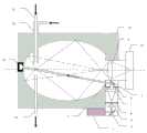
一种能实时检测微粒粒度及形状特征的光学传感器,其特征是:包括旋转对称椭腔镜,椭腔镜由金属制成、且内表面经抛光处理并镀有反射膜,在椭腔镜的外框上固装激光器,激光器射出的光束经第一反射镜后入射到第一透镜上,并形成扩束,在第一透镜后设置起消杂作用的第一光阑,在第一光阑后设置使入射光成为平行光束的第二透镜,第二透镜后设置减少光束截面积的第二光阑,第二光阑后设置使光束沿与椭腔镜长轴成小角方向入射到光敏区的第二反射镜,第二反射镜反射的光束截面线度与进出气通道线度一致,在第二反射镜后设置防止杂散光进入椭腔镜腔内的第三光阑,入射光束与样气流汇于光敏区,即椭腔镜的一焦点处,原方向入射光束射入光陷阱;所述光陷阱由金属制成,且内壁涂有吸光材料,并固定在椭腔镜的外框体内;样气的进、出气通道与椭腔镜长轴垂直,在样气进气通道外套装稀释纯净气通道,且稀释纯净气通道出口比样气进气通道出口更靠近光敏区;在椭腔镜的另一焦点后设置一物镜,该物镜接受大立体角范围的散射光被椭腔镜面反射至该焦点后的光线,在物镜的像平面上置一组合探测器,检测信号经组合探测器输出后放大、处理。An optical sensor capable of real-time detection of particle size and shape characteristics is characterized by: including a rotationally symmetrical elliptical cavity mirror, the elliptical cavity mirror is made of metal, and the inner surface is polished and coated with a reflective film. A laser is fixed on the outer frame. The beam emitted by the laser is incident on the first lens after passing through the first reflector, and forms a beam expansion. After the second lens is installed to make the incident light into a parallel beam, the second lens is installed behind the second aperture to reduce the cross-sectional area of the beam, and after the second aperture is installed to make the beam enter the photosensitive area along the direction of a small angle with the long axis of the elliptical cavity mirror The second reflector, the beam section line reflected by the second reflector is consistent with the line of the air inlet and outlet channels, and the third diaphragm is set behind the second reflector to prevent stray light from entering the elliptical cavity, and the incident beam is consistent with the sample The air flow converges in the photosensitive area, that is, a focal point of the elliptical cavity mirror, and the incident light beam in the original direction enters the light trap; the light trap is made of metal, and the inner wall is coated with light-absorbing materials, and is fixed in the outer frame of the elliptical cavity mirror The inlet and outlet channels of the sample gas are perpendicular to the long axis of the elliptical cavity mirror, and the diluted pure gas channel is installed outside the sample gas inlet channel, and the outlet of the diluted pure gas channel is closer to the photosensitive area than the outlet of the sample gas inlet channel; in the elliptical cavity An objective lens is set behind the other focal point of the mirror. The objective lens accepts the scattered light in a large solid angle range and is reflected by the elliptical cavity mirror to the focal point. A combined detector is placed on the image plane of the objective lens, and the detection signal passes through the combined detector. Amplify and process after output.
进、出气通道的直径为2mm。The diameter of the air inlet and outlet channels is 2mm.
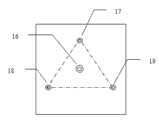
组合探测器由4个探测器组成,其中在中心位置即物镜的像点处是探测粒度的光电倍增管,另三个分别置于等边三角形的三顶点处的是主要用来检出微粒形状信息的光电管。The combined detector is composed of 4 detectors, among which the photomultiplier tube for particle size detection is located at the center position, that is, the image point of the objective lens, and the other three are respectively placed at the three vertices of the equilateral triangle, which are mainly used to detect the particle shape. information photocell.
本发明的工作原理是:半导体激光器发出的光束经扩束准直及光阑消杂光后,形成了一在光束截面上强度近于均匀的平行光,其入射至旋转对称椭腔镜的一焦点处,且入射方向与该椭腔镜的旋转对称长轴成一小角度,在该焦点处与经稀释的样气流相遇,即形成光敏区,由于增加了光敏区光强的均匀性,这样减小了由于微粒在光敏区位置不同的影响。由于采用了纯净气稀释法,减少了微粒在光敏区重叠的可能性以及在腔内的残留,提高了微粒计数及粒度的测量准确性;微粒在该处的散射光被旋转对称椭腔镜面反射至另一焦点,其散射角范围可达±2.5o~±145?o,或±170o~±180?o,而沿原入射方向的光射入光陷阱而被湮灭。包括前向在内的大空间角范围的接受设计,既保证了采集了微粒散射光的主要信息,又使得在测量粒度时,最大限度地减小了微粒形状及空间取向的影响。在整个椭腔镜内除了进出气通道外,别无它物,这样减少了杂散光的产生,而多个光阑的设置也减少了杂散光的影响,这样提高了仪器的信噪比。在此焦点后置一物镜作为收集透镜,在物镜像平面上置4个探测器, 其中一个在此透镜的像点,其它三个置于等边三角形的三顶点,位于像点处的光电倍增管作为测量粒度的主探测器,另三个探测器用来检测粒的形状,其原理是只要形状非球形,三角形三顶点的接受器就有不同的信号,对此三信号进行比较运算,可检测微粒形状,此外,这些信号也同时被用来作为微粒粒度检测信号的补充。The working principle of the present invention is: after the beam emitted by the semiconductor laser is expanded and collimated and the stray light is eliminated by the diaphragm, a parallel light with nearly uniform intensity on the beam section is formed, which is incident on a rotationally symmetrical elliptical cavity mirror. At the focal point, and the incident direction forms a small angle with the long axis of rotational symmetry of the elliptical cavity mirror, it meets the diluted sample gas flow at the focal point, which forms a photosensitive area. Since the uniformity of light intensity in the photosensitive area is increased, this reduces the The impact due to the different positions of the particles in the photosensitive area is small. Due to the use of the pure gas dilution method, the possibility of particles overlapping in the photosensitive area and the residue in the cavity are reduced, and the measurement accuracy of particle counting and particle size is improved; the scattered light of the particles is reflected by the mirror surface of the rotationally symmetrical elliptical cavity To another focal point, the range of scattering angle can reach ±2.5o~±145?o, or ±170o~±180?o, and the light along the original incident direction enters the light trap and is annihilated. The acceptance design of the large spatial angle range including the forward direction not only ensures the collection of the main information of the light scattered by the particles, but also minimizes the influence of particle shape and spatial orientation when measuring the particle size. There is nothing in the whole elliptical cavity except the air passage, which reduces the generation of stray light, and the setting of multiple apertures also reduces the influence of stray light, which improves the signal-to-noise ratio of the instrument. An objective lens is placed behind this focal point as a collection lens, and 4 detectors are placed on the objective mirror plane, one of which is at the image point of the lens, and the other three are placed at the three vertices of an equilateral triangle, and the photoelectric multiplier at the image point The tube is used as the main detector to measure the particle size, and the other three detectors are used to detect the shape of the particle. The principle is that as long as the shape is non-spherical, the receivers at the three vertices of the triangle will have different signals, and the three signals can be compared and detected. Particle shape, in addition, these signals are also used as a complement to the particle size detection signal.
本发明与现有技术相比,其显著优点是:1、既能测量微粒粒度又能同时标定微粒形状。2、不同与已有的前向透镜接受系统,采用椭腔镜接受,大大扩展了散射角的接受范围,最大限度地减小了微粒形状及空间取向对微粒粒度测量的影响。也不同与已有的侧向椭腔镜或二次曲面集光镜接受系统,采用从前向开始的散射接受设计,保证了微粒散射光的主要信息的接受,提高了测量精度。3、采用了纯净气稀释法,减少了微粒在光敏区重叠的可能性,提高了微粒计数、粒度及形状的测量准确性,同时也减少了腔内的残留与污染。4、椭腔镜内除了进出气通道,别无他物,最大限度地减少了杂散光的产生,提高了仪器的信噪比。5、扩束准直、光阑系统增加了光敏区光强的均匀性,减小了由于微粒在光敏区位置不同的影响,同时也减少了杂散光的影响。Compared with the prior art, the present invention has the following remarkable advantages: 1. It can not only measure the particle size but also calibrate the particle shape at the same time. 2. Different from the existing forward lens receiving system, the elliptical cavity mirror is used for receiving, which greatly expands the receiving range of scattering angle, and minimizes the influence of particle shape and spatial orientation on particle size measurement. It is also different from the existing side elliptical cavity mirror or quadric surface collector mirror receiving system. It adopts the scattering receiving design starting from the forward direction, which ensures the receiving of the main information of particle scattered light and improves the measurement accuracy. 3. The pure gas dilution method is adopted, which reduces the possibility of particles overlapping in the photosensitive area, improves the measurement accuracy of particle counting, particle size and shape, and also reduces the residue and pollution in the chamber. 4. There is nothing in the elliptical cavity mirror except the air inlet and outlet channels, which minimizes the generation of stray light and improves the signal-to-noise ratio of the instrument. 5. Beam expansion collimation and diaphragm system increase the uniformity of light intensity in the photosensitive area, reduce the influence of particles in the photosensitive area, and also reduce the influence of stray light.
附图说明Description of drawings
下面结合附图和实施例对本发明作进一步说明。The present invention will be further described below in conjunction with drawings and embodiments.
图1是本发明一个实施例的结构示意图。Fig. 1 is a structural schematic diagram of an embodiment of the present invention.
图2是图1中组合探测器10的具体布置示意图。FIG. 2 is a schematic diagram of the specific arrangement of the combined
具体实施方式Detailed ways
参见图1,由于半导体激光器1体积小,可固定在旋转对称椭腔镜10的外框上,其射出的光束经反射镜2后入射到透镜3上,并形成扩束,光阑4起消杂作用,透镜5使入射光成为平行光束,光阑6减小光束截面积,并使光束截面上各处强度均匀化,反射镜7使光束沿与椭腔镜长轴成小角方向准确入射到光敏区,此光束截面线度与进出气通道线度一致,直径2mm,光阑8防止杂散光进入腔内。整个光束产生及入射系统结构紧凑。入射光束与样气流汇于光敏区,即椭腔镜的一焦点处,原方向入射光束,射入光陷阱14,其由金属制成且内壁涂有吸光材料,并固定在旋转对称椭腔镜的外框体内。样气由11进气通道导入,经出气通道13流出,进出气通道与转对称椭腔镜的长轴垂直,稀释纯净气通道12外裹在进气通道上,其出口并比进气通道出口更靠近光敏区,这样达到稀释样气且减少微粒残留腔内的目的。椭腔镜由金属制成,内表面进行抛光处理并镀有反射膜,大立体角范围的散射光被椭腔镜面反射至另一焦点,并被该焦点后接受物镜9所接受,在物镜9的像平面上置一组合探测器15,检测信号经组合探测器15输出后放大、处理。Referring to Fig. 1, due to the small size of the semiconductor laser 1, it can be fixed on the outer frame of the rotationally symmetrical
参见图2,组合探测器15由4个探测器组成,其中在中心位置即物镜9的像点处是光电倍增管16,它是探测粒度的主探测器,另三个分别置于等边三角形的三顶点处的是光电管17、18、19,它们主要用来检出微粒形状信息,同时也用来作为粒度信息的补充;光电倍增管16位于上述等边三角形的中点。Referring to Fig. 2, combined
Claims (2)
Priority Applications (1)
| Application Number | Priority Date | Filing Date | Title |
|---|---|---|---|
| CN 201110346535CN102519850B (en) | 2011-11-07 | 2011-11-07 | Optical sensor capable of detecting granularity and shape feature of particles in real time |
Applications Claiming Priority (1)
| Application Number | Priority Date | Filing Date | Title |
|---|---|---|---|
| CN 201110346535CN102519850B (en) | 2011-11-07 | 2011-11-07 | Optical sensor capable of detecting granularity and shape feature of particles in real time |
Publications (2)
| Publication Number | Publication Date |
|---|---|
| CN102519850A CN102519850A (en) | 2012-06-27 |
| CN102519850Btrue CN102519850B (en) | 2013-04-24 |
Family
ID=46290846
Family Applications (1)
| Application Number | Title | Priority Date | Filing Date |
|---|---|---|---|
| CN 201110346535Expired - Fee RelatedCN102519850B (en) | 2011-11-07 | 2011-11-07 | Optical sensor capable of detecting granularity and shape feature of particles in real time |
Country Status (1)
| Country | Link |
|---|---|
| CN (1) | CN102519850B (en) |
Families Citing this family (17)
| Publication number | Priority date | Publication date | Assignee | Title |
|---|---|---|---|---|
| CN102564928B (en)* | 2012-01-09 | 2013-03-27 | 南通大学 | Sensor for optical particle counters |
| CN103196805B (en)* | 2013-04-02 | 2015-09-16 | 青岛众瑞智能仪器有限公司 | A kind of optical devices detecting aerosol quality and concentration |
| CN104390897B (en)* | 2013-07-22 | 2016-08-24 | 南通大学 | Improve detection molecule size and the optical system of shape of beam uniformity |
| CN104359804B (en)* | 2013-07-22 | 2017-10-17 | 南通大学 | Succinctly, the easily optical system of detection of particles size and shape |
| CN103364318B (en)* | 2013-07-22 | 2015-09-23 | 南通大学 | An Optical System for Detecting the Size and Shape of Particles Using a Rotationally Symmetric Elliptical Cavity Mirror |
| CN104458510B (en)* | 2013-07-22 | 2016-08-24 | 南通大学 | Improve detection of particles size and the optical system of shape of detection accuracy |
| CN103398671B (en)* | 2013-08-21 | 2014-11-26 | 南通大学 | Optical sensor of portable fast recognition instrument for fiber particles |
| US10732091B2 (en) | 2015-07-30 | 2020-08-04 | Trumpf Photonic Components Gmbh | Laser sensor for particle size detection |
| CN108169187B (en)* | 2017-12-15 | 2024-05-10 | 中国科学院西安光学精密机械研究所 | Test cavity for testing point source transmittance |
| CN108169084B (en)* | 2017-12-18 | 2021-04-20 | 中国科学院合肥物质科学研究院 | Aerosol particle shape and fluorescence detector |
| CN108226100B (en)* | 2018-01-15 | 2024-05-10 | 中国科学院西安光学精密机械研究所 | Improved cavity for point source transmittance test |
| WO2019237242A1 (en)* | 2018-06-12 | 2019-12-19 | 深圳达闼科技控股有限公司 | Detection system and signal enhancement device |
| TW202507260A (en)* | 2019-07-01 | 2025-02-16 | 美商應用材料股份有限公司 | Real-time detection of particulate matter during deposition chamber manufacturing |
| CN111307677A (en)* | 2019-11-22 | 2020-06-19 | 北京雪迪龙科技股份有限公司 | Laser front scattering particulate matter monitoring device |
| CN111947593B (en)* | 2020-08-07 | 2021-11-23 | 浙江大学 | Particle shape and surface roughness detection device and method based on optical trap |
| CN112630127B (en)* | 2021-03-10 | 2021-05-28 | 中国科学院上海高等研究院 | A vacuum particle counter |
| CN116148261A (en)* | 2023-01-05 | 2023-05-23 | 南通大学 | A detection device and method for optical element defect detection |
Family Cites Families (3)
| Publication number | Priority date | Publication date | Assignee | Title |
|---|---|---|---|---|
| CN2109569U (en)* | 1992-01-30 | 1992-07-08 | 中国科学院上海光学精密机械研究所 | Novel optical probe of laser dust particle counter |
| WO1993017322A1 (en)* | 1992-02-21 | 1993-09-02 | Secretary Of State For Defence In Her | Analysis of particle characteristics |
| CN101639435B (en)* | 2009-08-10 | 2011-12-14 | 中国人民解放军军事医学科学院卫生装备研究所 | Particle counter |
- 2011
- 2011-11-07CNCN 201110346535patent/CN102519850B/ennot_activeExpired - Fee Related
Also Published As
| Publication number | Publication date |
|---|---|
| CN102519850A (en) | 2012-06-27 |
Similar Documents
| Publication | Publication Date | Title |
|---|---|---|
| CN102519850B (en) | Optical sensor capable of detecting granularity and shape feature of particles in real time | |
| CN102564928B (en) | Sensor for optical particle counters | |
| CN106769802B (en) | Optical sensor of low-light background noise large-flow dust particle counter | |
| CN102308196B (en) | Compact Detector for Simultaneous Size and Fluorescence Detection of Particles | |
| CN101487786A (en) | Measurement sensor for inhalable dust concentration | |
| CN104807738B (en) | Device for detecting shapes of single aerosol particles in real time | |
| CN108956402B (en) | High-sensitivity dust concentration detection method with composite multi-photosensitive-area structure | |
| CN203587475U (en) | Cell and particle morphology optical detection device | |
| CN101162194A (en) | Optical senser of measurement dust particle | |
| CN102353621A (en) | Measuring device and method of light scattering particles | |
| CN112730180B (en) | A high-sensitivity dust particle counting sensor with dual detectors | |
| CN103487359A (en) | Full-automatic measuring device for form and distribution of laser excitated cells and particles | |
| CN102564929A (en) | High-flow dust particle counting sensor with novel photosensitive area structure | |
| CN103063626A (en) | Light path auto-correction cell laser excitation detecting device and detecting method thereof | |
| CN201116912Y (en) | Optical sensor to measure dust particles | |
| CN101968432B (en) | Multidimensional optical information sensor for analyzing physical properties of particles | |
| CN111795921B (en) | Illumination system for particle counter sensor beam homogenization and sharpening | |
| CN103364318B (en) | An Optical System for Detecting the Size and Shape of Particles Using a Rotationally Symmetric Elliptical Cavity Mirror | |
| CN104502376A (en) | X-ray nanometer imaging equipment and imaging analyzing system | |
| CN103364317B (en) | Optical system for detecting size and shape of micro-particles | |
| CN201130141Y (en) | Dust Particle Counter Optical Sensor | |
| CN208766107U (en) | A fluorescence collection device of a fluorescence detector | |
| CN104390896B (en) | Measurement precision improved optical system for detecting size and shape of microparticle | |
| CN202471562U (en) | Large-flow dust particle counting sensor with novel photosensitive region structure | |
| CN203191316U (en) | Cell laser excitation detection device with automatic correction of optical path |
Legal Events
| Date | Code | Title | Description |
|---|---|---|---|
| C06 | Publication | ||
| PB01 | Publication | ||
| C10 | Entry into substantive examination | ||
| SE01 | Entry into force of request for substantive examination | ||
| C14 | Grant of patent or utility model | ||
| GR01 | Patent grant | ||
| CF01 | Termination of patent right due to non-payment of annual fee | Granted publication date:20130424 Termination date:20151107 | |
| EXPY | Termination of patent right or utility model |