CN102519716A - Test stand for performance of linear electromechanical actuator - Google Patents
Test stand for performance of linear electromechanical actuatorDownload PDFInfo
- Publication number
- CN102519716A CN102519716ACN2011103969827ACN201110396982ACN102519716ACN 102519716 ACN102519716 ACN 102519716ACN 2011103969827 ACN2011103969827 ACN 2011103969827ACN 201110396982 ACN201110396982 ACN 201110396982ACN 102519716 ACN102519716 ACN 102519716A
- Authority
- CN
- China
- Prior art keywords
- electromechanical actuator
- linear electromechanical
- pressure sensor
- assembly
- straight line
- Prior art date
- Legal status (The legal status is an assumption and is not a legal conclusion. Google has not performed a legal analysis and makes no representation as to the accuracy of the status listed.)
- Granted
Links
- 238000012360testing methodMethods0.000titleabstractdescription19
- 238000006073displacement reactionMethods0.000claimsabstractdescription32
- 238000011056performance testMethods0.000claimsabstractdescription15
- 230000000712assemblyEffects0.000claimsdescription2
- 238000000429assemblyMethods0.000claimsdescription2
- 230000033001locomotionEffects0.000abstractdescription7
- 238000005259measurementMethods0.000abstractdescription7
- 230000001133accelerationEffects0.000abstractdescription5
- 230000003068static effectEffects0.000abstractdescription5
- 230000004044responseEffects0.000abstractdescription4
- 238000009434installationMethods0.000description20
- 210000004907glandAnatomy0.000description6
- 238000000034methodMethods0.000description5
- 229910000831SteelInorganic materials0.000description3
- 238000013461designMethods0.000description3
- 238000012423maintenanceMethods0.000description3
- 230000007246mechanismEffects0.000description3
- 238000012545processingMethods0.000description3
- 230000009467reductionEffects0.000description3
- 239000010959steelSubstances0.000description3
- 230000008569processEffects0.000description2
- 238000003466weldingMethods0.000description2
- RZVHIXYEVGDQDX-UHFFFAOYSA-N9,10-anthraquinoneChemical compoundC1=CC=C2C(=O)C3=CC=CC=C3C(=O)C2=C1RZVHIXYEVGDQDX-UHFFFAOYSA-N0.000description1
- 230000009471actionEffects0.000description1
- 238000012415analytical developmentMethods0.000description1
- 230000009286beneficial effectEffects0.000description1
- 230000005540biological transmissionEffects0.000description1
- 230000036541healthEffects0.000description1
- 238000004806packaging method and processMethods0.000description1
- 238000011160researchMethods0.000description1
- 238000005096rolling processMethods0.000description1
- 230000008054signal transmissionEffects0.000description1
Images


Landscapes
- Investigating Strength Of Materials By Application Of Mechanical Stress (AREA)
Abstract
Translated fromChinese
Description
Translated fromChinese所属领域Field
本发明涉及一种用于直线机电作动器性能试验的机械装置。The invention relates to a mechanical device used for the performance test of a linear electromechanical actuator.
现有技术current technology
直线机电作动器以其精度高、频响快、体积小、重量轻、生存能力强、无污染和维护方便等优点正逐步取代传统的液压作动器,并广泛应用于飞控系统、精密机床、食品包装等各行各业。直线机电作动器主要由电机、减速机构、滚珠丝杠(或滚柱丝杠)和电控系统四部分组成,通过丝杠的旋转和滚动体的行星运动,将动力传递给螺母以实现直线输出。直线机电作动器的直线作动性能直接影响到作动对象的控制精度、速度和效率等,故需要对作动器进行性能试验。Linear electromechanical actuators are gradually replacing traditional hydraulic actuators due to their advantages of high precision, fast frequency response, small size, light weight, strong survivability, no pollution and convenient maintenance, and are widely used in flight control systems, precision Machine tools, food packaging and other industries. The linear electromechanical actuator is mainly composed of four parts: the motor, the reduction mechanism, the ball screw (or roller screw) and the electric control system. Through the rotation of the screw and the planetary motion of the rolling body, the power is transmitted to the nut to achieve a straight line. output. The linear actuation performance of the linear electromechanical actuator directly affects the control accuracy, speed and efficiency of the actuated object, so it is necessary to perform a performance test on the actuator.
现有技术中,相关性能试验台主要集中于对作动系统的传动部分进行测试,即对滚珠丝杠的性能进行测试,如文献“精密滚珠丝杠副摩擦力矩波动的分析与测试”和“高速滚珠丝杠副动力学性能分析及其试验研究”中,分别对滚珠丝杠的摩擦力矩和综合动力学性能进行了测试和研究,这类试验台没有将电机和减速机构的性能考虑进去,无法体现测量直线作动器的整体性能指标。而对整个作动系统的性能试验,国内少有的试验台大多采用液压系统作为作动器的加载装置,结构相对复杂,而且存在液压源易污染、维护不方便和占用面积大等问题。国外已有采用机电作动器作为加载装置的整体性能试验台,如文献“Experimental andAnalytical Development of Health Management for Electro-Mechanical Actuators”,但这种试验台成本较高,同时需要设计加载装置的控制系统,增加了试验台设计、加工和操作的复杂性。In the prior art, the relevant performance test bench mainly focuses on testing the transmission part of the actuation system, that is, testing the performance of the ball screw, such as the literature "Analysis and Test of Friction Torque Fluctuation of Precision Ball Screw Pair" and " In "Dynamic Performance Analysis and Experimental Research of High-speed Ball Screw Pair", the friction torque and comprehensive dynamic performance of the ball screw were tested and studied respectively. This type of test bench did not take the performance of the motor and the reduction mechanism into consideration. It cannot reflect the overall performance index of the linear actuator. As for the performance test of the entire actuation system, most of the domestic rare test benches use a hydraulic system as the loading device for the actuator. The structure is relatively complex, and there are problems such as easy pollution of the hydraulic source, inconvenient maintenance, and large occupation area. There are overall performance test benches using electromechanical actuators as loading devices in foreign countries, such as the literature "Experimental and Analytical Development of Health Management for Electro-Mechanical Actuators", but the cost of this test bench is relatively high, and it is necessary to design the control system of the loading device , which increases the complexity of test bench design, processing and operation.
发明内容Contents of the invention
本发明的目的是:为了克服现有直线机电作动器性能试验台多采用液压系统作为加载装置,存在易污染、难维护、占地大等问题,同时没有综合考虑电机和减速机构的性能,无法测试作动系统的整体性能指标等诸多不足,提供一种测量精度高、测试范围宽、无污染、操作简便的直线机电作动器性能试验台。The purpose of the present invention is: in order to overcome the problems that the existing linear electromechanical actuator performance test bench mostly uses a hydraulic system as the loading device, which has problems such as easy pollution, difficult maintenance, and large area occupation, and does not comprehensively consider the performance of the motor and the reduction mechanism. There are many shortcomings such as the inability to test the overall performance index of the actuation system, and a linear electromechanical actuator performance test bench with high measurement accuracy, wide test range, no pollution, and easy operation is provided.
本发明的技术方案是,一种直线机电作动器性能试验台,包括底板、滑轮组件、导轨组件、拉压力传感器组件、负载砝码、直线机电作动器和位移传感器组件。The technical solution of the present invention is a linear electromechanical actuator performance test bench, including a base plate, a pulley assembly, a guide rail assembly, a tension and pressure sensor assembly, load weights, a linear electromechanical actuator, and a displacement sensor assembly.
底板为其他各部件提供支撑;The bottom plate provides support for other components;
固定在底板上的直线机电作动器的输出杆顶端有内螺纹,该内螺纹与连接杆一端形成螺纹连接;所述连接杆方向与直线机电作动器的作动方向一致;The top of the output rod of the linear electromechanical actuator fixed on the bottom plate has an internal thread, and the internal thread forms a threaded connection with one end of the connecting rod; the direction of the connecting rod is consistent with the actuating direction of the linear electromechanical actuator;
所述导轨组件由滑轨和滑块组成,滑轨固定安装在底板上,且滑轨方向与直线机电作动器的作动方向平行;The guide rail assembly is composed of a slide rail and a slider, the slide rail is fixedly installed on the bottom plate, and the direction of the slide rail is parallel to the actuating direction of the linear electromechanical actuator;
所述拉压力传感器组件主要包括安装座、前端支撑轴、拉压力传感器和后端支撑轴;所述安装座的四边立壁形成的空腔结构,其底壁固连在导轨组件的滑块上;前端支撑轴和后端支撑轴分别贯穿于安装座的前端和后端立壁的圆柱孔,所述的拉压力传感器的两端分别固连在前端支撑轴和后端支撑轴相向的一端;且前端支撑轴固定在安装座上,后端支撑轴的另一端与前述的连接杆另一端固连;The tension pressure sensor assembly mainly includes a mounting base, a front support shaft, a tension pressure sensor and a rear end support shaft; the cavity structure formed by the four side walls of the mounting base, the bottom wall of which is fixedly connected to the slider of the guide rail assembly; The front-end support shaft and the rear-end support shaft penetrate through the cylindrical holes of the front-end and rear-end vertical walls of the mounting seat respectively, and the two ends of the tension pressure sensor are fixedly connected to the opposite ends of the front-end support shaft and the rear-end support shaft respectively; and the front end The support shaft is fixed on the mounting seat, and the other end of the rear support shaft is fixedly connected with the other end of the aforementioned connecting rod;
所述位移传感器组件主要包括位移传感器、弹性安装架和L形连接片,位移传感器通过弹性安装架安装在底座上,位移传感器的测量杆与固连在安装座上的L形连接片固连;The displacement sensor assembly mainly includes a displacement sensor, an elastic mounting frame and an L-shaped connecting piece, the displacement sensor is installed on the base through the elastic mounting frame, and the measuring rod of the displacement sensor is fixedly connected with the L-shaped connecting piece fixedly connected on the mounting seat;
所述滑轮组件由滑轮支架、滑轮和轴销组成;四组滑轮组件固定在底板上,且其分布位置关于直线机电作动器的作动方向对称;The pulley assembly is composed of a pulley bracket, a pulley and a shaft pin; four sets of pulley assemblies are fixed on the bottom plate, and their distribution positions are symmetrical with respect to the actuating direction of the linear electromechanical actuator;
所述负载砝码为相同的两组,分别由两组细绳通过两个滑轮连接在拉压力传感器组件的安装座上;滑轮和连接点之间段细绳的方向与直线机电作动器的作动方向平行。The load weights are the same two groups, which are respectively connected by two groups of thin ropes to the mounting base of the tension pressure sensor assembly through two pulleys; the direction of the thin rope between the pulley and the connection point is consistent with the The direction of action is parallel.
在测量直线机电作动器性能指标时,通过挂载负载砝码进行加载,控制直线机电作动器的运动参数,由拉压力传感器组件可以测量直线机电作动器的动载荷,由位移传感器组件可以测量输出速度和输出加速度等参数,从而获得直线机电作动器的性能参数;在控制直线机电作动器处于保持的状态下,通过逐渐增加砝码的重量,可以测量直线机电作动器的静载荷;在不挂载负载砝码即空载条件下,由位移传感器组件可以测量直线机电作动器的行程、最大速度、响应时间等性能参数。When measuring the performance index of the linear electromechanical actuator, load the load weight to control the motion parameters of the linear electromechanical actuator. The dynamic load of the linear electromechanical actuator can be measured by the tension and pressure sensor assembly, and the displacement sensor assembly It can measure parameters such as output speed and output acceleration, so as to obtain the performance parameters of the linear electromechanical actuator; in the state of controlling the linear electromechanical actuator, by gradually increasing the weight of the weight, the linear electromechanical actuator can be measured Static load: Under the condition of no load weight or no load, the displacement sensor component can measure the performance parameters of the linear electromechanical actuator, such as stroke, maximum speed, and response time.
本发明的有益效果是:设计的直线机电作动器性能试验台能够对直线作动器施加不同大小的恒定轴向拉压力,从而能够模拟不同负载。该直线机电作动器试验台能够测量直线作动器的静动载荷、作动行程、作动速度、作动加速度、响应时间等性能参数。具有测量精度高、测试范围宽、无污染、操作简便等优点。The beneficial effect of the invention is that the designed linear electromechanical actuator performance test bench can apply different magnitudes of constant axial tension pressure to the linear actuator, thereby simulating different loads. The linear electromechanical actuator test bench can measure performance parameters such as static and dynamic load, actuating stroke, actuating speed, actuating acceleration, and response time of the linear actuator. It has the advantages of high measurement accuracy, wide test range, no pollution, and easy operation.
附图和附图说明DRAWINGS AND DESCRIPTIONS OF DRAWINGS
图1是本发明提出的直线机电作动器性能试验台结构轴测图;Fig. 1 is the axonometric view of the linear electromechanical actuator performance test bench structure proposed by the present invention;
图2是本发明提出的直线机电作动器性能试验台结构俯视图;Fig. 2 is a top view of the linear electromechanical actuator performance test bench structure proposed by the present invention;
图3是基座框架轴测图;Fig. 3 is an axonometric view of the base frame;
图4是基座轴测图;Fig. 4 is a base axonometric view;
图5是拉压力传感器组件及滑块剖视图;Fig. 5 is a sectional view of the tension pressure sensor assembly and the slider;
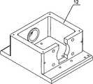
图6是安装座轴测图;Figure 6 is an axonometric view of the mount;
图7是后端支撑轴轴测图;Fig. 7 is an axonometric view of the rear end support shaft;
图8是连接杆轴测图;Figure 8 is an axonometric view of the connecting rod;
其中:1.基座框架;2.控制系统放置板;3.外壳;4.柜门;5.底板;6.滑轮支架;7.滑轮;8.轴销;9.滑轨;10.滑块;11.支撑块;12.安装座;13.前端支撑轴;14.螺母;15.拉压力传感器;16.后端支撑轴;17.压盖;18.封盖;19.挂钩;20.细绳;21.负载砝码;22.连接杆;23.销轴;24.销;25.L-U形支架;26.直线机电作动器;27.位移传感器;28.弹性安装架;29.L形连接片Among them: 1. Base frame; 2. Control system placement board; 3. Shell; 4. Cabinet door; 5. Bottom plate; 6. Pulley bracket; 7. Pulley; Block; 11. Support block; 12. Mounting seat; 13. Front-end support shaft; 14. Nut; 15. Pull pressure sensor; 16. Back-end support shaft; 17. Gland; .string; 21. load weight; 22. connecting rod; 23. pin shaft; 24. pin; 25. L-U-shaped bracket; 26. linear electromechanical actuator; 27. displacement sensor; 28. elastic mounting frame; 29 .L-shaped connecting piece
具体实施实例Specific implementation examples
实施例1:Example 1:
参阅图1图2,本实施例中的直线机电作动器性能试验台包括基座、底板5、滑轮组件、导轨组件、支撑组件、拉压力传感器组件、砝码组件、销轴连接组件、L-U形支架25、直线机电作动器26和位移传感器组件。基座用来支撑整个试验台,并且为负载砝码21的运动提供足够的高度空间;底板5通过螺栓固定安装在基座上表面;滑轮组件固定安装在底板的两端;试验过程中负载砝码21通过细绳20与拉压力传感器组件相连并挂在滑轮组件上;导轨由滑轨9和滑块10组成,滑轨9与底板5通过螺栓固定安装,滑块10与拉压力传感器组件通过螺栓固连;支撑组件通过螺栓固定安装在底板5上,分别安装在滑轨9的两侧;L-U型支架25通过螺栓固定安装在底板5上,沿着底板5长度方向,L-U型支架25对称平面和导轨9对称平面共面;直线机电作动器26通过螺栓安装在L-U型支架25上,并通过销轴与拉压力传感器组件相连;位移传感器组件与直线机电作动器26平行安装在底板5上,伸出的测量杆通过使用L型连接片29与拉压力传感器组件连结起来。Referring to Figure 1 and Figure 2, the linear electromechanical actuator performance test bench in this embodiment includes a base, a base plate 5, a pulley assembly, a guide rail assembly, a support assembly, a tension pressure sensor assembly, a weight assembly, a pin connection assembly, and a L-U
参阅图3、图4,基座包括基座框架1、控制系统放置板2、外壳3和柜门4。基座框架1为三层的方形框架结构,自下而上分别为2层控制系统放置板安装梁和底座安装梁,基座框架1的各个梁之间通过焊接工艺固连。控制系统放置板安装梁上开有孔,用于固定安装控制系统放置板2;底座安装梁上分布有16个孔,用于通过螺栓与底板5连接。控制系统放置板2为一块长方形薄板,上面分布三个通孔,用于和控制系统放置板安装梁固定连接。外壳3为一U形的薄板,通过焊接与基座框架1固连在一起,外壳3的一边侧壁上分布有四个圆孔,从而能够使控制系统的线路顺利通过,与直线机电作动器26连接。柜门4通过铰链与外壳3连结,从而能够控制其开合,方便放置控制系统,从而节省试验台空间。Referring to FIG. 3 and FIG. 4 , the base includes a base frame 1 , a control
底板5为一个长方形的钢板,板上分布有一系列的不同直径的螺纹孔和通孔38个,用来安装试验台的各个组件。这些安装孔主要有基座安装孔、滑轮组件安装孔、导轨安装孔、支撑组件安装孔、L-U型支架安装孔和位移传感器组件安装孔。其中基座安装孔为通孔,用于实现和基座连接,其他均为螺纹孔,用来安装试验台零件和仪器。The bottom plate 5 is a rectangular steel plate, and there are a series of 38 threaded holes and through holes of different diameters distributed on the plate, which are used to install various components of the test bench. These installation holes mainly include base installation holes, pulley assembly installation holes, guide rail installation holes, support assembly installation holes, L-U type bracket installation holes and displacement sensor assembly installation holes. The mounting holes of the base are through holes for connecting with the base, and the others are threaded holes for installing test bench parts and instruments.
滑轮组件主要由三部分组成,分别为滑轮支架6、滑轮7和轴销8,滑轮7通过轴销8安装在滑轮支架6上部。滑轮组件底部有两个通孔,通过螺栓固定安装在底板5上。Pulley assembly mainly is made up of three parts, is respectively pulley bracket 6, pulley 7 and pivot pin 8, and pulley 7 is installed on pulley bracket 6 tops by pivot pin 8. There are two through holes at the bottom of the pulley assembly, which are fixed on the base plate 5 by bolts.
导轨组件由滑轨9和滑块10组成,其中滑轨9两端各有一个沉头螺栓安装孔,与底板5通过沉头螺栓固定安装;其中滑块10有两个,各分布有4个螺纹孔,与拉压力传感器组件通过螺栓固连。The guide rail assembly is composed of a slide rail 9 and a
支撑块11为截面为长方形的钢条,共有两个,对称分布安装在导轨9的两侧,高度略低于滑块10的安装高度,从而防止试验测试过程中拉压力传感器组件受力过大发生倾斜。支撑块11两端各分布一个沉头螺栓安装孔,通过沉头螺栓固定安装底板5上。The support block 11 is a steel bar with a rectangular cross-section, and there are two in total, which are symmetrically distributed and installed on both sides of the guide rail 9, and the height is slightly lower than the installation height of the
参阅图5,拉压力传感器组件主要由七部分组成,分别为安装座12、前端支撑轴13、螺母14、拉压力传感器15、后端支撑轴16、压盖17和封盖18。安装座12为一个长方形带凸耳的腔体,长方形空腔的前端立壁上有一个圆柱孔,并且孔的两个端面均有凸台,从而增大前端支撑轴13所受支持力面积,此立壁的外侧两各有一个螺纹孔,用来安装挂钩19;空腔相对的后端立壁切出一个两端长方形中间圆形组合而成的缺口,用来安装后端支撑轴16,此立壁的外侧两边也各有一个螺纹孔,用来安装挂钩19;安装座12的顶端四角均有螺纹孔,用来实现封盖18的安装;参阅图6,安装座12的底部分布有八个用于安装的孔,其中四个孔均布在凸耳上,四个孔分布在空腔底面上,用来实现和导轨组件连接安装。前端支撑轴13为一个较短的阶梯轴,两端分布有螺纹。前端支撑轴13安装在安装座12空腔前端的圆柱孔内,并通过螺母14固定安装在安装座12上,前端支撑轴13的另一端与拉压力传感器15通过螺纹连接。拉压力传感器15为S型,两端梁上均有螺纹孔,拉压力传感器15的另一端通过螺纹连接与后端支撑轴16固连。参阅图7,后端支撑轴16的另一端是一个双耳片,用来实现销轴连接,后端支撑轴16由压盖17支撑。压盖17主体轮廓为一个长方形薄板,中心部位有一个圆柱孔,为了增加支撑面积,孔的一个端面设计有凸台。压盖17的四个角上各分布一个圆形通孔,用来实现和安装座12的螺栓固定连接,压盖17的下部开有两个方形缺口,从而能够避免与安装座12的安装螺栓发生干涉。封盖18为方形薄板,四角各分布一个圆孔,用来实现与安装座12的固连,同时,封盖18的中心有个圆孔,从而保证拉压力传感器15的供电线路和信号传输线路的连接。Referring to FIG. 5 , the pull-pressure sensor assembly is mainly composed of seven parts, which are mounting
砝码组件主要由三部分组成,分别为挂钩19、细绳20和负载砝码21。挂钩19分别安装在拉压力传感器组件安装座12的立壁侧面上,细绳20连接挂钩19和负载砝码21并将负载砝码21挂在滑轮组件上。The weight assembly is mainly composed of three parts, namely a hook 19 , a string 20 and a
销轴连接组件主要由三部分组成,分别为连接杆22、销轴23和销24。参阅图8,连接杆22一端为单耳片,与后端支撑轴16的双耳片通过销轴连接,另一端为螺纹孔,与直线机电作动器26输出杆相连。The pin shaft connection assembly mainly consists of three parts, which are respectively a connecting
L-U形支架25主体为L形的钢板,在上端面开有一个长方形缺口,从而形成两个立壁,在两立壁高度方向分布有三个通孔,用来通过螺栓安装直线机电作动器26。L-U形支架25的底部开有两排通槽,通过螺纹连接,可以将L-U形支架25与底板5连接。由于支架的底部为通槽,所以可以调节机电直线作动器26在底板5长度方向上的位置,从而能够灵活地满足安装需求,避免设计、加工、装配等误差给安装带来的麻烦。The main body of the L-U-shaped
直线机电作动器26的安装方式为双侧面螺栓安装,输出杆顶端分布有内螺纹,能够与连接杆22通过螺纹连接。The installation method of the linear
位移传感器组件主要由三部分组成,分别为位移传感器27、弹性安装架28和L形连接片29。位移传感器27通过弹性安装架28安装在底座5上,并且位移传感器27的位置可调,从而能够灵活地满足安装条件,位移传感器27的测量杆上分布有螺纹。L形连接片29上开有能够实现连接的孔,通过螺栓连接将L形连接片29与拉压力传感器组件固连,通过螺母将位移传感器27的测量杆与L形连接片29连接,从而能够将测量杆和拉压力传感器组件连接起来,实现位移的精确测量。The displacement sensor assembly is mainly composed of three parts, namely a displacement sensor 27 , an
本实施例在测量直线机电作动器26的动态性能指标时,以测量推力为例,首先通过砝码组件给直线机电作动器26施加动态载荷,方式为在安装座12的后端立壁上安装挂钩19,通过细绳20将指定载荷的负载砝码21挂在滑轮组件上。In this embodiment, when measuring the dynamic performance index of the linear
测量过程中,通过设定直线机电作动器26控制系统的控制参数,包括位移和速度等,直线机电作动器26以一定的推力输出,通过拉压力组件测量出直线机电作动器26的输出推力,通过位移传感器27测量出直线机电作动器26的输出位移参数,通过数据处理,进而获得其速度和加速度参数。During the measurement process, by setting the control parameters of the linear
测量直线机电作动器26拉力和反向运动参数时,砝码组件的安装方式和直线机电作动器26的控制方式同上相反。When measuring the pulling force and reverse motion parameters of the linear
实施例2:Example 2:
本实施例在测量直线机电作动器26的静载荷时,通过控制系统控制直线机电作动器26处于保持状态,逐渐增加负载砝码21的重量,可以通过拉压力传感器组件测量出其静载荷。In this embodiment, when measuring the static load of the linear
实施例3:Example 3:
本实施例在测量直线机电作动器26的空载性能参数时,试验过程中不挂载砝码组件。测量过程中,通过设定直线机电作动器26的控制系统的控制参数,包括位移和驱动速度等,直线机电作动器26以一定的速度输出运动,通过位移传感器27测量出直线机电作动器26的输出位移参数,通过数据处理,进而获得其速度和加速度参数。In this embodiment, when measuring the no-load performance parameters of the linear
测量直线机电作动器26空载时的反向运动参数时,直线机电作动器26的控制方式同上相反。When measuring the reverse movement parameters of the linear
Claims (2)
Priority Applications (1)
| Application Number | Priority Date | Filing Date | Title |
|---|---|---|---|
| CN201110396982.7ACN102519716B (en) | 2011-12-02 | 2011-12-02 | Test stand for performance of linear electromechanical actuator |
Applications Claiming Priority (1)
| Application Number | Priority Date | Filing Date | Title |
|---|---|---|---|
| CN201110396982.7ACN102519716B (en) | 2011-12-02 | 2011-12-02 | Test stand for performance of linear electromechanical actuator |
Publications (2)
| Publication Number | Publication Date |
|---|---|
| CN102519716Atrue CN102519716A (en) | 2012-06-27 |
| CN102519716B CN102519716B (en) | 2014-06-11 |
Family
ID=46290712
Family Applications (1)
| Application Number | Title | Priority Date | Filing Date |
|---|---|---|---|
| CN201110396982.7AExpired - Fee RelatedCN102519716B (en) | 2011-12-02 | 2011-12-02 | Test stand for performance of linear electromechanical actuator |
Country Status (1)
| Country | Link |
|---|---|
| CN (1) | CN102519716B (en) |
Cited By (27)
| Publication number | Priority date | Publication date | Assignee | Title |
|---|---|---|---|---|
| CN103398842A (en)* | 2013-08-21 | 2013-11-20 | 常州星宇车灯股份有限公司 | Force application device for motor fatigue test |
| CN103411789A (en)* | 2013-08-23 | 2013-11-27 | 南京理工大学 | Simple loading and testing device for dynamic characteristics of actuator |
| CN103575520A (en)* | 2013-10-23 | 2014-02-12 | 芜湖市顺昌汽车配件有限公司 | Device for measuring carrying capacity of clamp |
| CN103616172A (en)* | 2013-11-26 | 2014-03-05 | 西北工业大学 | Linear electromechanical actuator performance test experiment table capable of simulating work mounting environment |
| CN103698116A (en)* | 2013-12-13 | 2014-04-02 | 西北工业大学 | Spring-loaded performance test experiment table for linear electro-mechanical actuator |
| CN104458228A (en)* | 2014-11-28 | 2015-03-25 | 济南瑞晟机械有限公司 | External limit actuator |
| KR101567850B1 (en) | 2014-07-03 | 2015-11-11 | 한국기계연구원 | The attraction force measuring equipment for solenoid actuator |
| CN104180977B (en)* | 2014-05-27 | 2016-10-05 | 西北工业大学 | Multifunctional linear electromechanical actuator performance test stand |
| CN106324499A (en)* | 2016-08-02 | 2017-01-11 | 东南大学 | Dynamic performance test device for linear rotating motor and testing method |
| CN106370370A (en)* | 2016-08-17 | 2017-02-01 | 中国航空工业集团公司西安飞行自动控制研究所 | Rapidly changeable actuator vibration test clamp |
| CN106586021A (en)* | 2016-12-28 | 2017-04-26 | 中国航空工业集团公司西安飞机设计研究所 | Determination method for remainder stroke of actuator |
| CN106769001A (en)* | 2016-11-26 | 2017-05-31 | 陕西理工学院 | The unidirectional loading running in machine of planetary roller screw pair |
| CN104267289B (en)* | 2014-10-08 | 2017-05-31 | 兰州飞行控制有限责任公司 | One kind linear motion electric actuator loading bench |
| CN107042510A (en)* | 2017-04-12 | 2017-08-15 | 华中科技大学 | A kind of hydraulic series flexible drive mechanism and test its experiment porch |
| CN107097037A (en)* | 2017-05-27 | 2017-08-29 | 福州大学 | A kind of high-voltage pulse current reparative experiment platform and its application method |
| CN107389327A (en)* | 2017-07-13 | 2017-11-24 | 江西洪都航空工业集团有限责任公司 | Miniature actuator long duration test control system |
| CN107702900A (en)* | 2017-08-31 | 2018-02-16 | 北京精密机电控制设备研究所 | A kind of cylindrical compression spring load test method and system |
| CN107966258A (en)* | 2016-10-20 | 2018-04-27 | 北京精密机电控制设备研究所 | A kind of qualitative attribute simulator |
| CN108956176A (en)* | 2018-08-10 | 2018-12-07 | 中国石油大学(华东) | A kind of high-precision hydraulic damper and the dynamic and static test platform of actuator |
| CN109946102A (en)* | 2019-04-16 | 2019-06-28 | 北京华锴盛泽科技有限公司 | Push-pull effort testboard |
| CN111075777A (en)* | 2018-10-18 | 2020-04-28 | 南京龙航国健电子科技有限公司 | Anti-lateral force electro-hydraulic servo actuator |
| CN111693305A (en)* | 2020-05-25 | 2020-09-22 | 浙江美力汽车弹簧有限公司 | Stabilizer bar durability test device and test method |
| CN112985868A (en)* | 2021-03-23 | 2021-06-18 | 西北工业大学 | Fault simulation experiment device for electromechanical actuator |
| CN114577503A (en)* | 2022-04-19 | 2022-06-03 | 长春国科精密光学技术有限公司 | Piezoelectric actuator performance test platform |
| CN115219126A (en)* | 2022-01-11 | 2022-10-21 | 广州汽车集团股份有限公司 | Test device for testing suspension rigidity |
| CN117302540A (en)* | 2023-09-14 | 2023-12-29 | 成都飞机工业(集团)有限责任公司 | Device and method for testing actuator of folding bolt of airplane wing |
| CN120293695A (en)* | 2024-07-01 | 2025-07-11 | 成都翼昀航空科技有限公司 | A test system for linear actuators |
Citations (5)
| Publication number | Priority date | Publication date | Assignee | Title |
|---|---|---|---|---|
| JP2005003525A (en)* | 2003-06-12 | 2005-01-06 | Mori Seiki Co Ltd | Rotational angle position measuring device |
| CN1727867A (en)* | 2004-07-26 | 2006-02-01 | 西南交通大学 | Bidirectional Electromechanical Actuated Shock Absorber Test Bench |
| CN101608966A (en)* | 2009-07-24 | 2009-12-23 | 哈尔滨工程大学 | A semi-active vibration isolation electromagnetic actuator test bench |
| KR101015038B1 (en)* | 2010-06-09 | 2011-02-16 | 엘아이지넥스원 주식회사 | Actuator Test Device |
| CN202433177U (en)* | 2011-12-02 | 2012-09-12 | 西北工业大学 | Straight line electro-mechanical actuator performance test stand |
- 2011
- 2011-12-02CNCN201110396982.7Apatent/CN102519716B/ennot_activeExpired - Fee Related
Patent Citations (5)
| Publication number | Priority date | Publication date | Assignee | Title |
|---|---|---|---|---|
| JP2005003525A (en)* | 2003-06-12 | 2005-01-06 | Mori Seiki Co Ltd | Rotational angle position measuring device |
| CN1727867A (en)* | 2004-07-26 | 2006-02-01 | 西南交通大学 | Bidirectional Electromechanical Actuated Shock Absorber Test Bench |
| CN101608966A (en)* | 2009-07-24 | 2009-12-23 | 哈尔滨工程大学 | A semi-active vibration isolation electromagnetic actuator test bench |
| KR101015038B1 (en)* | 2010-06-09 | 2011-02-16 | 엘아이지넥스원 주식회사 | Actuator Test Device |
| CN202433177U (en)* | 2011-12-02 | 2012-09-12 | 西北工业大学 | Straight line electro-mechanical actuator performance test stand |
Cited By (39)
| Publication number | Priority date | Publication date | Assignee | Title |
|---|---|---|---|---|
| CN103398842A (en)* | 2013-08-21 | 2013-11-20 | 常州星宇车灯股份有限公司 | Force application device for motor fatigue test |
| CN103411789A (en)* | 2013-08-23 | 2013-11-27 | 南京理工大学 | Simple loading and testing device for dynamic characteristics of actuator |
| CN103575520A (en)* | 2013-10-23 | 2014-02-12 | 芜湖市顺昌汽车配件有限公司 | Device for measuring carrying capacity of clamp |
| CN103575520B (en)* | 2013-10-23 | 2017-01-11 | 芜湖市顺昌汽车配件有限公司 | Device for measuring carrying capacity of clamp |
| CN103616172A (en)* | 2013-11-26 | 2014-03-05 | 西北工业大学 | Linear electromechanical actuator performance test experiment table capable of simulating work mounting environment |
| CN103616172B (en)* | 2013-11-26 | 2016-07-06 | 西北工业大学 | Linear electromechanical actuator performance test experiment table capable of simulating working and mounting environments |
| CN103698116A (en)* | 2013-12-13 | 2014-04-02 | 西北工业大学 | Spring-loaded performance test experiment table for linear electro-mechanical actuator |
| CN103698116B (en)* | 2013-12-13 | 2016-07-06 | 西北工业大学 | Spring-loaded linear electromechanical actuator performance test experiment table |
| CN104180977B (en)* | 2014-05-27 | 2016-10-05 | 西北工业大学 | Multifunctional linear electromechanical actuator performance test stand |
| KR101567850B1 (en) | 2014-07-03 | 2015-11-11 | 한국기계연구원 | The attraction force measuring equipment for solenoid actuator |
| CN104267289B (en)* | 2014-10-08 | 2017-05-31 | 兰州飞行控制有限责任公司 | One kind linear motion electric actuator loading bench |
| CN104458228A (en)* | 2014-11-28 | 2015-03-25 | 济南瑞晟机械有限公司 | External limit actuator |
| CN104458228B (en)* | 2014-11-28 | 2017-01-25 | 济南瑞晟机械有限公司 | External limit actuator |
| CN106324499A (en)* | 2016-08-02 | 2017-01-11 | 东南大学 | Dynamic performance test device for linear rotating motor and testing method |
| CN106370370A (en)* | 2016-08-17 | 2017-02-01 | 中国航空工业集团公司西安飞行自动控制研究所 | Rapidly changeable actuator vibration test clamp |
| CN106370370B (en)* | 2016-08-17 | 2019-01-25 | 中国航空工业集团公司西安飞行自动控制研究所 | A kind of actuator vibration test fixture that can be quickly converted |
| CN107966258A (en)* | 2016-10-20 | 2018-04-27 | 北京精密机电控制设备研究所 | A kind of qualitative attribute simulator |
| CN106769001A (en)* | 2016-11-26 | 2017-05-31 | 陕西理工学院 | The unidirectional loading running in machine of planetary roller screw pair |
| CN106586021A (en)* | 2016-12-28 | 2017-04-26 | 中国航空工业集团公司西安飞机设计研究所 | Determination method for remainder stroke of actuator |
| CN106586021B (en)* | 2016-12-28 | 2019-06-25 | 中国航空工业集团公司西安飞机设计研究所 | A kind of actuator remainder stroke determines method |
| CN107042510B (en)* | 2017-04-12 | 2020-01-21 | 华中科技大学 | Hydraulic series elastic driving mechanism and experiment platform for testing same |
| CN107042510A (en)* | 2017-04-12 | 2017-08-15 | 华中科技大学 | A kind of hydraulic series flexible drive mechanism and test its experiment porch |
| CN107097037B (en)* | 2017-05-27 | 2023-08-11 | 福州大学 | High-voltage pulse current repair experiment platform and application method thereof |
| CN107097037A (en)* | 2017-05-27 | 2017-08-29 | 福州大学 | A kind of high-voltage pulse current reparative experiment platform and its application method |
| CN107389327A (en)* | 2017-07-13 | 2017-11-24 | 江西洪都航空工业集团有限责任公司 | Miniature actuator long duration test control system |
| CN107702900B (en)* | 2017-08-31 | 2019-05-24 | 北京精密机电控制设备研究所 | A kind of cylindrical compression spring load test method and system |
| CN107702900A (en)* | 2017-08-31 | 2018-02-16 | 北京精密机电控制设备研究所 | A kind of cylindrical compression spring load test method and system |
| CN108956176A (en)* | 2018-08-10 | 2018-12-07 | 中国石油大学(华东) | A kind of high-precision hydraulic damper and the dynamic and static test platform of actuator |
| CN111075777A (en)* | 2018-10-18 | 2020-04-28 | 南京龙航国健电子科技有限公司 | Anti-lateral force electro-hydraulic servo actuator |
| CN109946102A (en)* | 2019-04-16 | 2019-06-28 | 北京华锴盛泽科技有限公司 | Push-pull effort testboard |
| CN109946102B (en)* | 2019-04-16 | 2024-06-04 | 北京芯金源测控技术有限公司 | Push-pull force test board |
| CN111693305A (en)* | 2020-05-25 | 2020-09-22 | 浙江美力汽车弹簧有限公司 | Stabilizer bar durability test device and test method |
| CN112985868B (en)* | 2021-03-23 | 2023-04-07 | 西北工业大学 | Fault simulation experiment device for electromechanical actuator |
| CN112985868A (en)* | 2021-03-23 | 2021-06-18 | 西北工业大学 | Fault simulation experiment device for electromechanical actuator |
| CN115219126A (en)* | 2022-01-11 | 2022-10-21 | 广州汽车集团股份有限公司 | Test device for testing suspension rigidity |
| CN114577503A (en)* | 2022-04-19 | 2022-06-03 | 长春国科精密光学技术有限公司 | Piezoelectric actuator performance test platform |
| CN117302540A (en)* | 2023-09-14 | 2023-12-29 | 成都飞机工业(集团)有限责任公司 | Device and method for testing actuator of folding bolt of airplane wing |
| CN117302540B (en)* | 2023-09-14 | 2024-07-12 | 成都飞机工业(集团)有限责任公司 | Device and method for testing actuator of folding bolt of airplane wing |
| CN120293695A (en)* | 2024-07-01 | 2025-07-11 | 成都翼昀航空科技有限公司 | A test system for linear actuators |
Also Published As
| Publication number | Publication date |
|---|---|
| CN102519716B (en) | 2014-06-11 |
Similar Documents
| Publication | Publication Date | Title |
|---|---|---|
| CN102519716B (en) | Test stand for performance of linear electromechanical actuator | |
| CN202433177U (en) | Straight line electro-mechanical actuator performance test stand | |
| CN106052931B (en) | Multi-rope hoisting steel wire rope tension self-balancing test bed and method | |
| CN102401764B (en) | Model loading device | |
| CN102607837B (en) | Cage type linear electromechanical actuator performance test bed | |
| CN204150834U (en) | Elevator no-load equilibrium factor detecting device | |
| CN106297529B (en) | A kind of double-station servo mechanism load simulator | |
| CN108709906A (en) | A kind of magnetic control shape memory alloy material drive characteristic test platform and test method | |
| CN103558050A (en) | Multifunctional load stimulation test stand | |
| CN106990007A (en) | Material residual stress and case hardness relation test method and device | |
| WO2020206829A1 (en) | Fretting fatigue test apparatus and method for steel wire under radial impact condition | |
| CN106168535A (en) | A kind of fatigue load assay device of leaf springs of car | |
| CN102735486A (en) | Device for testing indicator characteristic of magnetorheological damper | |
| CN110792656A (en) | Hydraulic cylinder testing device | |
| CN104368967A (en) | Device capable of adjusting and measuring pretightening force loss of ball screw pair and experiment table of device | |
| CN108375516A (en) | A kind of horizontal linear motor driving medium-high frequency fatigue tester | |
| CN110411772B (en) | Elevator no-load static traction test detection method and device | |
| CN109809275A (en) | An online detection device for uneven tension of traction wire rope and its working method | |
| CN106323776A (en) | Fatigue testing device of damping pad | |
| CN104267289A (en) | Rectilinear motion electric actuator loading table | |
| CN201130126Y (en) | Automatic test device for tension and compression force of spiral cable | |
| CN101957271B (en) | High-speed large-displacement servo loading test platform | |
| CN105692378B (en) | A kind of elevator no-load coefficient of balance detection means based on hydraulic cylinder straight top type | |
| CN2748904Y (en) | Rock direct shear test machine | |
| CN204269362U (en) | The pneumatically loading ball screw assembly, dynamic efficiency testing table of interchangeable leading screw |
Legal Events
| Date | Code | Title | Description |
|---|---|---|---|
| C06 | Publication | ||
| PB01 | Publication | ||
| C10 | Entry into substantive examination | ||
| SE01 | Entry into force of request for substantive examination | ||
| C14 | Grant of patent or utility model | ||
| GR01 | Patent grant | ||
| CF01 | Termination of patent right due to non-payment of annual fee | Granted publication date:20140611 Termination date:20151202 | |
| EXPY | Termination of patent right or utility model |