CN102519394B - High-adaptability three-dimensional measuring method based on color structured light - Google Patents
High-adaptability three-dimensional measuring method based on color structured lightDownload PDFInfo
- Publication number
- CN102519394B CN102519394BCN201110366865.6ACN201110366865ACN102519394BCN 102519394 BCN102519394 BCN 102519394BCN 201110366865 ACN201110366865 ACN 201110366865ACN 102519394 BCN102519394 BCN 102519394B
- Authority
- CN
- China
- Prior art keywords
- color
- grating
- pixel
- phase
- component
- Prior art date
- Legal status (The legal status is an assumption and is not a legal conclusion. Google has not performed a legal analysis and makes no representation as to the accuracy of the status listed.)
- Expired - Fee Related
Links
Images


Landscapes
- Length Measuring Devices By Optical Means (AREA)
- Image Processing (AREA)
Abstract
Translated fromChinese
Description
Translated fromChinese技术领域technical field
本发明属于三维信息重构的技术领域,基于彩色光栅投影,结合傅里叶变换法,将条纹投影轮廓术用于物体的三维测量。整个系统涉及彩色投影光栅设计,图像分割,相位获取等部分。The invention belongs to the technical field of three-dimensional information reconstruction, and uses fringe projection profilometry for three-dimensional measurement of objects based on color grating projection and Fourier transform method. The whole system involves color projection grating design, image segmentation, phase acquisition and other parts.
背景技术Background technique
三维轮廓检测及其重构技术是计算机图像处理技术的一个分支,是计算机视觉和计算机图形图像处理相结合的一个研究方向,它在生产自动化、机器人视觉、CAD、虚拟现实和医学映像诊断等领域都有着广泛的应用前景。3D contour detection and reconstruction technology is a branch of computer image processing technology, and a research direction combining computer vision and computer graphics and image processing. It is widely used in the fields of production automation, robot vision, CAD, virtual reality and medical image diagnosis. All have broad application prospects.
由于光栅投影法具有检测过程完全非接触、数据空间分辨率高、一次性瞬间投影直接实现三维空间物体形状检测和获取三维信息等特点,同时,由于彩色图像比黑白图像携带更丰富的信息,近年来,结构光法中基于彩色光栅投影的三维测量技术得到了较大的发展。其测量方法是:首先设计若干幅辅助光栅图像,包括彩色编码条纹和带有不同相移角度的几幅相移条纹图,这些辅助图像的设计要有利于采集图像后的彩色图像分割、解码和解相位的实现。然后将它们用投影仪依次投影到被测物体表面,形成因被测物体表面形状调制而畸变的光栅条纹,并用彩色CCD采集图像。对采集到的彩色编码条纹图进行彩色图像分割,识别各条纹的颜色和边界,从而以此为依据解码得到各条纹的位置编码,即相位周期数信息,彩色图像分割效果的好坏直接决定了解码的质量,因此设计适当的彩色图像分割算法至关重要,解码算法则对应于不同的彩色编码算法;对采集到的相移图解相位得到主值相位信息。基于相位主值和相位周期数进行相位展开,计算得出与采集到图像中每个像素唯一对应的绝对相位信息,进而得到被测物体的三维信息,实现三维重构。彩色光栅的优点是可利用条纹颜色记录更多的被测物体的相位信息,达到减少图像采集数量、提高相位法实时性的目。Because the grating projection method has the characteristics of completely non-contact detection process, high spatial resolution of data, one-time instant projection to directly realize the shape detection of three-dimensional space objects and obtain three-dimensional information, and at the same time, because color images carry more information than black and white images, in recent years, In the past, the three-dimensional measurement technology based on color grating projection in the structured light method has been greatly developed. The measurement method is: first design several auxiliary raster images, including color-coded fringes and several phase-shifted fringe images with different phase shift angles. The design of these auxiliary images should be conducive to the color image segmentation, decoding and resolution phase realization. Then they are sequentially projected onto the surface of the measured object with a projector to form distorted grating stripes due to the modulation of the surface shape of the measured object, and the image is collected with a color CCD. Carry out color image segmentation on the collected color-coded fringe image, identify the color and boundary of each fringe, and then decode the position code of each fringe based on this, that is, the information of the phase cycle number. The quality of the color image segmentation directly determines the Therefore, it is very important to design an appropriate color image segmentation algorithm, and the decoding algorithm corresponds to different color coding algorithms; the main value phase information is obtained from the collected phase shift diagram phase. Phase unwrapping is performed based on the main value of the phase and the number of phase cycles, and the absolute phase information uniquely corresponding to each pixel in the collected image is calculated, and then the three-dimensional information of the measured object is obtained to realize three-dimensional reconstruction. The advantage of the color grating is that the stripe color can be used to record more phase information of the measured object, so as to reduce the number of image acquisitions and improve the real-time performance of the phase method.
在光栅条纹图中,通过给待求相位场加上已知或未知的常相位,来得到新的条纹图,即增加求解条件。这种通过对条纹图相位场进行移相来增加若干常量相位而得到多幅条纹图用以求解相位场的方法,称为相移法。固然相移法采用多幅条纹图像解出相位,在相位求解的精度方面有突出的优势,但这种方法通常需要向被测物体投影多幅条纹图像,大大限制了测量动态性能的提高。在以相位法为基础的条纹图像处理方法中,基于傅里叶变换进行解相位通常仅需要一幅图像,很多学者将此与彩色编码光栅结合用于物体三维信息的提取,无疑为实现动态测量以及实时性能的改善提供的思路。基于彩色光栅投影的三维测量技术涉及两大关键技术环节,即彩色编码光栅的设计和相位的求解。In the grating fringe pattern, a new fringe pattern is obtained by adding a known or unknown constant phase to the phase field to be obtained, that is, adding a solution condition. This method of obtaining multiple fringe patterns to solve the phase field by adding several constant phases by shifting the phase field of the fringe pattern is called the phase shift method. Although the phase shift method uses multiple fringe images to solve the phase, which has outstanding advantages in the accuracy of the phase solution, but this method usually needs to project multiple fringe images to the measured object, which greatly limits the improvement of the measurement dynamic performance. In the fringe image processing method based on the phase method, only one image is usually required for dephasing based on Fourier transform. Many scholars combine this with color-coded gratings for the extraction of three-dimensional information of objects, undoubtedly for the realization of dynamic measurement. And the ideas provided by the improvement of real-time performance. The 3D measurement technology based on color grating projection involves two key technical links, namely the design of color coded grating and the solution of phase.
彩色编码条纹是一组指定颜色条纹的序列,其长度由测量范围要求而定,通常以整个序列周期的投射范围能完全覆盖被测物体为宜。任何彩色条纹编码都必须满足以下条件:任意相邻两条纹颜色不同;且任意编码周期的颜色序列都不相同,即在解码时不会产生歧义而导致解码错误。在彩色编码条纹的设计中,为了使条纹颜色容易区分,通常选择颜色区分度大的纯色进行编码,对于红色R、绿色G、蓝色B三个分量,只选用0和255两个灰阶,这样三个分量可以构成八种纯色:白色(255,255,255)、红色(255,0,0),绿色(0,255,0)、蓝色(0,0,255)、黑色(0,0,0)、青色(0,255,255)、品色(255,0,255)、黄色(255,255,0);其中各颜色后面的括号内分别是红色(R)、绿色(G)、蓝色(B)三个分量的灰度值。颜色的选取需要根据不同颜色的特点、被测物体的特点、彩色分割的难易程度等方面的考虑来完成。彩色编码的方法很多,其中格雷码属于可靠性编码,这种编码相邻的两个码组之间只有一位不同,是一种错误最小化的编码。Gray编码的主要优点是:思路简洁明了,易于编程实现。Color-coded stripes are a sequence of specified color stripes, the length of which is determined by the requirements of the measurement range, and usually it is appropriate that the projection range of the entire sequence period can completely cover the measured object. Any color stripe coding must meet the following conditions: any two adjacent stripes have different colors; and the color sequence of any coding cycle is different, that is, there will be no ambiguity during decoding and cause decoding errors. In the design of color-coded stripes, in order to make the color of the stripes easy to distinguish, a solid color with high color discrimination is usually selected for coding. For the three components of red R, green G, and blue B, only two gray scales of 0 and 255 are used. Such three components can form eight pure colors: white (255, 255, 255), red (255, 0, 0), green (0, 255, 0), blue (0, 0, 255), black (0 , 0, 0), cyan (0, 255, 255), magenta (255, 0, 255), yellow (255, 255, 0); the brackets behind each color are red (R), green ( G), the gray value of the three components of blue (B). The selection of color needs to be completed according to the characteristics of different colors, the characteristics of the measured object, and the difficulty of color segmentation. There are many methods of color coding, among which Gray code belongs to reliability coding, and this kind of coding has only one bit difference between two adjacent code groups, which is a kind of error-minimizing coding. The main advantages of Gray coding are: the idea is concise and clear, and it is easy to program and realize.
对编码条纹解码的过程即是获取条纹周期信息的过程。条纹颜色用于记录相位周期信息,通过正确识别条纹的颜色及边界,然后对编码条纹正确解码后,便可得到相位周期信息从而实现相位展开。彩色图像分割的过程实则为还原图像中各像素颜色的过程。彩色图像分割有很多种经典的算法,包括基于颜色相似系数的分割方法、HSI颜色空间下的迭代阈值分割方法、基于区域的自适应阈值分割方法等。The process of decoding the coded stripes is the process of obtaining the stripe period information. The fringe color is used to record the phase period information. By correctly identifying the color and boundary of the fringe, and then decoding the coded fringe correctly, the phase period information can be obtained to realize the phase unwrapping. The process of color image segmentation is actually the process of restoring the color of each pixel in the image. There are many classic algorithms for color image segmentation, including segmentation methods based on color similarity coefficients, iterative threshold segmentation methods in HSI color space, adaptive threshold segmentation methods based on regions, etc.
解相位主要通过两个步骤,即求包裹相位和相位周期展开。包裹相位的求解精度较好的方法就是经典的相移法,现今,由于测量动态性能要求的日益突显,在物体表面不存在较大高度不连续的情况下,利用基于傅里叶变化的方法解包裹相位也成为一个较好的选择。此外,在相位展开技术上,除传统的灰阶码法中利用7幅逐步二分的黑白条纹图加以确定相位的周期信息,还有基于边缘跳变检测、基于质量图指导等方法,此类算法一般是利用了图像的灰度信息,并且算法实现较复杂;而利用彩色编码携带的颜色信息加以确定相位周期,不但减少了采集图像的数量,算法复杂程度低,在不影响精度的前提下,能很好的改善测量的动态性能,因此基于彩色编码光栅投影的三维测量方法的应用日趋广泛。Solving the phase is mainly through two steps, that is, finding the wrapped phase and phase period expansion. The method with better solution accuracy of wrapped phase is the classic phase shift method. Nowadays, due to the increasingly prominent requirements of measurement dynamic performance, in the case that there is no large height discontinuity on the surface of the object, the method based on Fourier change is used to solve the problem. Wrapping aspects also become a better choice. In addition, in terms of phase unwrapping technology, in addition to the traditional gray-scale code method using seven progressively dichotomized black and white fringe images to determine the periodic information of the phase, there are also methods based on edge jump detection and quality map guidance. Generally, the grayscale information of the image is used, and the algorithm implementation is more complicated; and the phase period is determined by using the color information carried by the color code, which not only reduces the number of collected images, but also reduces the complexity of the algorithm. On the premise of not affecting the accuracy, It can improve the dynamic performance of the measurement very well, so the application of the three-dimensional measurement method based on the color-coded grating projection is becoming more and more extensive.
综上所述,在基于彩色光栅投影的三维测量方法中,随着精度和速度要求的日益提高,测量对象其特性日益复杂,测量流程中彩色光栅的设计,彩色图像分割,相位求解等都需要继续深入的研究,以期在测量具有复杂表面特性的情况下保证精度,扩大三维测量的适用范围。To sum up, in the three-dimensional measurement method based on color grating projection, with the increasing accuracy and speed requirements, the characteristics of the measurement object are becoming more and more complex. The design of color grating, color image segmentation, phase solution, etc. in the measurement process require Continue in-depth research in order to ensure accuracy in the case of measuring complex surface properties and expand the scope of application of three-dimensional measurement.
发明内容Contents of the invention
针对现有三维测量技术中尚存的不足和限制,本发明旨在提供一种高适应性彩色结构光三维测量方法。Aiming at the existing deficiencies and limitations in the existing three-dimensional measurement technology, the present invention aims to provide a highly adaptable color structured light three-dimensional measurement method.
本发明采用如下技术方案:The present invention adopts following technical scheme:
一种高适应性彩色结构光三维测量方法,具体步骤如下:A highly adaptable color structured light three-dimensional measurement method, the specific steps are as follows:
步骤1:设计彩色光栅:Step 1: Design the Color Raster:
步骤11:列出用于编码的六种纯色:采用对24位真彩图像三个分量R、G、B分别赋值实现,24位真彩图像的R、G、B分量分别是8位,有256个灰阶,把每个分量只取0和255两个值,并将灰阶为255时记为1,灰阶为0时记为0,这样R、G、B分量的取值分别为0或1,们选取红(100)、品红(101)、蓝(001)、青(011)、绿(010)、黄(110)六色进行编码,Step 11: List the six pure colors used for encoding: by assigning values to the three components R, G, and B of the 24-bit true-color image respectively, the R, G, and B components of the 24-bit true-color image are 8 bits respectively, and there are 256 gray scales, each component only takes two values of 0 and 255, and records the gray scale as 1 when the gray scale is 255, and records it as 0 when the gray scale is 0, so the values of the R, G, and B components are respectively 0 or 1, we choose red (100), magenta (101), blue (001), cyan (011), green (010), yellow (110) six colors to encode,
步骤1.2:选择彩色条纹的数目为33条,并为彩色条纹编号:蓝(001)、青(011)、绿(010)、黄(110)、红(100)、品红(101)条纹编号依次记为1、2、3、4、5、6,Step 1.2: Select the number of colored stripes as 33, and number the colored stripes: blue (001), cyan (011), green (010), yellow (110), red (100), magenta (101) stripe numbers Recorded as 1, 2, 3, 4, 5, 6 in turn,
步骤1.3:确定编码周期,并列出长度为此编码周期的所有可能的彩色条纹编码组合:以4个彩色条纹为编码周期,根据步骤1.2中设定的编号,满足格雷编码且编码周期为4个彩色条纹的所有可能的彩色条纹编码组合的集合s为:Step 1.3: Determine the encoding period, and list all possible color stripe encoding combinations with the length of this encoding period: 4 color stripes are used as the encoding period, according to the number set in step 1.2, gray encoding is satisfied and the encoding period is 4 The set s of all possible color-stripe coding combinations of a color-stripe is:
s={s={
1234,1232,1212,1216,1654,1656,1616,1612,1234, 1232, 1212, 1216, 1654, 1656, 1616, 1612,
2345,2343,2323,2321,2165,2161,2121,2123,2345, 2343, 2323, 2321, 2165, 2161, 2121, 2123,
3456,3454,3434,3432,3216,3212,3232,3234,3456, 3454, 3434, 3432, 3216, 3212, 3232, 3234,
4561,4565,4545,4543,4321,4323,4343,4345,4561, 4565, 4545, 4543, 4321, 4323, 4343, 4345,
5612,5616,5656,5654,5432,5434,5454,5456,5612, 5616, 5656, 5654, 5432, 5434, 5454, 5456,
6123,6121,6161,6165,6543,6545,6565,6561,6123, 6121, 6161, 6165, 6543, 6545, 6565, 6561,
}}
步骤1.4:确定各个编码周期的彩色条纹编码:Step 1.4: Determine the color stripe coding for each coding cycle:
步骤1.4.1:建立彩色条纹集合Io且彩色条纹集合Io为空,将步骤1.3中列出的所有可能的彩色条纹编码组合的集合s作为待选区,从集合s中任意选择一个彩色条纹编码组合设为sj,j=0,并将彩色条纹编码组合sj中的四个元素依序列入彩色条纹集合Io,在彩色条纹集合Io中形成彩色条纹序列,并将彩色条纹编码组合sj从集合s中删除,集合s中剩余元素形成选择下一个彩色条纹编码组合的待选区sr,Step 1.4.1: Establish the color stripe set Io and the color stripe set Io is empty, take the set s of all possible color stripe coding combinations listed in step 1.3 as the candidate area, and randomly select a color stripe from the set s The coding combination is set to sj , j=0, and the four elements in the color stripe coding combination sj are sequenced into the color stripe set Io , forming a color stripe sequence in the color stripe set Io , and encoding the color stripes The combination sj is deleted from the set s, and the remaining elements in the set s form the candidate area sr for selecting the next color stripe coding combination,
步骤1.4.2:取彩色条纹编码组合sj的后3个元素作为当前所选彩色条纹编码组合sj+1的前3个元素并以此作为候选条件,从待选区sr中寻找满足候选条件的彩色条纹编码组合sj+1,将彩色条纹编码组合sj+1的最后一个元素补入Io并列于彩色条纹序列的尾部,同时,从sr中删除彩色条纹编码组合sj+1,集合s中剩余元素形成的选择下一个彩色条纹编码组合的待选区,Step 1.4.2: Take the last 3 elements of the color stripe coding combination sj as the first 3 elements of the currently selected color stripe coding combination sj+1 and use them as candidate conditions, and search for candidate conditions from the candidate region sr The color stripe coding combination sj+1 of the color stripe coding combination sj+1, the last element of the color stripe coding combination s j+1 is added to Io and arranged at the tail of the color stripe sequence, and at the same time, the color stripe coding combination sj+1 is deleted from sr, The remaining elements in the set s form the candidate area for selecting the next color stripe coding combination,
步骤1.4.3:如果j+1=33,则彩色条纹集合Io的彩色条纹序列为投影光栅的编码,并进入步骤1.5;否则,令j=j+1,返回步骤1.4.2,Step 1.4.3: If j+1=33, the color fringe sequence of the color fringe set Io is the code of the projected grating, and enter step 1.5; otherwise, let j=j+1, return to step 1.4.2,
步骤1.5:对设计完成的彩色编码条纹序列中RGB分量依据公式(1)做正弦调制最终得到用于投影的彩色光栅,Step 1.5: Perform sinusoidal modulation on the RGB components in the designed color-coded stripe sequence according to formula (1) to finally obtain the color grating for projection,
式中,I′rn(x,y),I′gn(x,y),I′bn(x,y)分别表示用于投影的彩色光栅的第n条编码条纹的R、G、B分量,Irn(x,y),Ign(x,y),Ibn(x,y)分别表示彩色编码条纹序列的第n条编码条纹的R、G、B分量,ω为条纹宽度,其值为32个像素,x、y分别表示横、纵方向像素坐标,像素点(x,y)为所属单个条纹内横向的第t个像素,t的取值在0~ω之间,In the formula, I′rn (x, y), I′gn (x, y), I′bn (x, y) respectively represent the R, G, and B components of the nth coded stripe of the color grating used for projection , Irn (x, y), Ign (x, y), Ibn (x, y) respectively represent the R, G, and B components of the nth coded stripe of the color coded stripe sequence, ω is the stripe width, and The value is 32 pixels, x and y represent the horizontal and vertical pixel coordinates respectively, the pixel point (x, y) is the tth pixel in the horizontal direction of the single stripe to which it belongs, and the value of t is between 0 and ω.
步骤1.6:对步骤1.5得到的彩色光栅,依据公式(2)计算得到辅助光栅,Step 1.6: For the color grating obtained in step 1.5, calculate the auxiliary grating according to formula (2),
式中,I′rn(x,y),I′gn(x,y),I′bn(x,y)分别表示用于投影的彩色光栅的第n条编码条纹的R、G、B分量,I″rn(x,y),I″gn(x,y),I″bn(x,y)分别表示辅助光栅的第n条编码条纹其R、G、B分量,In the formula, I′rn (x, y), I′gn (x, y), I′bn (x, y) respectively represent the R, G, and B components of the nth coded stripe of the color grating used for projection , I″rn (x, y), I″gn (x, y), I″bn (x, y) respectively represent the R, G, and B components of the nth coded stripe of the auxiliary grating,
步骤2:通过计算机和投影仪分别将彩色光栅与辅助光栅投影到被测物体上,并用摄像机分别取回彩色光栅与辅助光栅的变形图,Step 2: Project the color grating and auxiliary grating onto the measured object through the computer and the projector, and use the camera to retrieve the deformation maps of the color grating and auxiliary grating respectively,
步骤3:对取回彩色光栅与辅助光栅的变形图进行处理,计算其各像素点的反射率,并根据反射率对彩色光栅的变形图进行补偿:Step 3: Process the deformation map of the retrieved color grating and auxiliary grating, calculate the reflectance of each pixel, and compensate the deformation map of the color grating according to the reflectance:
步骤3.1:根据式(3)计算其各像素点的反射率:Step 3.1: Calculate the reflectance of each pixel according to formula (3):
式中,x、y分别表示横、纵方向像素坐标,kr(x,y),kg(x,y),kb(x,y)分别表示彩色光栅的变形图的像素点(x,y)的R、G、B分量反射率,R′(x,y),G′(x,y),B′(x,y)分别表示辅助光栅的变形图的像素点(x,y)的R、G、B分量,R(x,y),G(x,y),B(x,y)分别表示彩色光栅的变形图的像素点(x,y)的R、G、B分量,In the formula, x and y represent the horizontal and vertical pixel coordinates respectively, and kr (x, y), kg (x, y), and kb (x, y) represent the pixels of the deformed image of the color grating (x , y) R, G, B component reflectance, R'(x, y), G'(x, y), B'(x, y) respectively represent the pixel points (x, y) of the deformation map of the auxiliary grating ), R(x, y), G(x, y), B(x, y) respectively represent R, G, B of the pixel point (x, y) of the deformed image of the color raster weight,
步骤3.2:根据式(4)对彩色光栅的变形图进行补偿:Step 3.2: Compensate the deformation map of the color grating according to formula (4):
式中,x、y分别表示横、纵方向像素坐标,kr(x,y),kg(x,y),kb(x,y)分别表示彩色光栅的变形图的像素点(x,y)的R、G、B分量反射率,R″(x,y),G″(x,y),B″(x,y)分别表示补偿后的彩色光栅变形图的像素点(x,y)的R、G、B分量,R(x,y),G(x,y),B(x,y)分别表示彩色光栅的变形图的像素点(x,y)的R、G、B分量,In the formula, x and y represent the horizontal and vertical pixel coordinates respectively, and kr (x, y), kg (x, y), and kb (x, y) represent the pixels of the deformed image of the color grating (x , y) R, G, B component reflectance, R″(x, y), G″(x, y), B″(x, y) respectively represent the pixels of the compensated color grating deformation map (x , y) of the R, G, B components, R (x, y), G (x, y), B (x, y) respectively represent the R, G of the pixel point (x, y) of the deformation map of the color raster , B component,
步骤4:对补偿后的彩色光栅变形图进行处理,得到包裹相位、相位周期信息和最终相位图像,Step 4: Process the compensated color grating deformation map to obtain the wrapped phase, phase period information and the final phase image,
步骤4.1:通过CCD采集得到彩色光栅变形图与辅助光栅变形图,使用Matrox Meteor II图卡将采集到的图像传输至计算机处理,经步骤3得到补偿后的彩色光栅变形图,将补偿后的彩色光栅变形图转换到HSV空间,取V分量作为补偿后的彩色光栅变形图的光强分布图,该光强分布图表达式如下:Step 4.1: Obtain the color grating deformation map and auxiliary grating deformation map through CCD acquisition, use the Matrox Meteor II graphics card to transfer the collected images to the computer for processing, obtain the compensated color grating deformation map through

式中,x、y分别表示横、纵方向像素坐标,a(x,y)为背景光强,b(x,y)为调制光强,I(x,y)为彩色光栅变形图中的光强分布图在(x,y)位置处的光强,ρ为彩色投影光栅中的单个彩色条纹宽度,j为虚数单位,
由欧拉公式原理,式(5)可改写为如下形式:According to the principle of Euler's formula, formula (5) can be rewritten as the following form:
I(x,y)=a(x,y)+c(x,y)exp(2πjf0x)+c*(x,y)exp(-2πjf0x) (6)I(x, y) = a(x, y) + c(x, y) exp(2πjf0 x) + c* (x, y) exp(-2πjf0 x) (6)
其中,
x、y分别表示横、纵方向像素坐标,c*(x,y)为c(x,y)的共轭复数,j为虚数单位,f0为投影光栅在参考面上未变形条纹的空间频率,x and y represent the horizontal and vertical pixel coordinates respectively, c* (x, y) is the conjugate complex number of c(x, y), j is the imaginary unit, and f0 is the space of the undeformed stripes of the projected grating on the reference surface frequency,
对式(6)中所示的一维光强信号I(x,y)沿着正x方向进行一维傅里叶变换,可得,Performing a one-dimensional Fourier transform on the one-dimensional light intensity signal I(x, y) shown in formula (6) along the positive x direction, we can get,
F[I(x,y)]=A(f,y)+C(f-f0,y)+C*(f+f0,y) (8)F[I(x,y)]=A(f,y)+C(ff0 ,y)+C* (f+f0 ,y) (8)
式中F[I(x,y)],A(f,y),C(f-f0,y),C*(f+f0,y)分别表示I(x,y),c(x,y),c*(x,y)对应频域中的傅里叶频谱,然后滤波提取含有相位信息的基频分量C(f-f0,y),通过基频分量做逆傅里叶变换得到c(x,y)exp(2πjf0x),得到彩色光栅变形图的包裹相位图,包裹相位值为In the formula, F[I(x, y)], A(f, y), C(f-f0, y), C* (f+f0, y) represent I(x, y), c(x, y), c* (x, y) corresponds to the Fourier spectrum in the frequency domain, and then filter to extract the fundamental frequency component C(ff0 , y) containing phase information, and obtain c by inverse Fourier transform of the fundamental frequency component (x, y)exp(2πjf0 x), get the wrapped phase map of the color grating deformation map, and the wrapped phase value is

这里解得的
步骤4.2:对补偿后的彩色光栅变形图进行彩色分割:Step 4.2: Perform color segmentation on the compensated color grating deformation map:
将补偿后的彩色光栅变形图转换至HSV空间,将S分量与V分量均赋值为255以消除亮度和饱和度的影响,然后将处理后的彩色光栅变形图转换回RGB空间,对RGB三分量分别用大津法进行阈值分割,Convert the compensated color raster deformation map to HSV space, assign the S component and V component to 255 to eliminate the influence of brightness and saturation, and then convert the processed color raster deformation map back to RGB space, and the RGB three-component Threshold segmentation using the Otsu method, respectively,
步骤4.3:解码:Step 4.3: Decoding:
对步骤4.2得到的彩色分割结果进行解码,得出彩色分割结果中的彩色条纹与用于投影的彩色光栅中各条纹的对应关系,即求得它们对应的位置编码,这个位置编码也就是相位周期性展开中用到的相位周期信息,解码的具体步骤如下:Decode the color segmentation result obtained in step 4.2 to obtain the corresponding relationship between the color stripes in the color segmentation result and the stripes in the color grating used for projection, that is, to obtain their corresponding position codes, which is also the phase period The phase period information used in the sexual expansion, the specific steps of decoding are as follows:
步骤4.3.1:数据预处理,首先建立一个标志数组,其元素数与图像中像素数相等,即数组的每个元素都与图像中相应位置的像素对应,将图像中出现的六种颜色蓝色、青色、绿色、黄色、红色、品红编号为1、2、3、4、5、6,标志数组中存储的就是彩色分割结果对应位置像素的颜色编号,这样可以避免在后续处理中多次访问像素的三个颜色分量而影响处理速度,Step 4.3.1: Data preprocessing, first create a flag array, the number of elements of which is equal to the number of pixels in the image, that is, each element of the array corresponds to the pixel at the corresponding position in the image, and the six colors blue that appear in the image Color, cyan, green, yellow, red, and magenta are numbered 1, 2, 3, 4, 5, and 6, and the flag array stores the color number of the pixel corresponding to the color segmentation result, which can avoid redundant processing in subsequent processing. The processing speed is affected by accessing the three color components of the pixel at a time,
步骤4.3.2:对标志数组进行遍历,把其中的分量分组为背景部分和有用条纹信息部分,以减少需要处理的数据量,Step 4.3.2: Traversing the flag array, grouping the components into the background part and the useful stripe information part to reduce the amount of data to be processed,
步骤4.3.3:逐行遍历得出改善后的彩色分割结果中各行各像素对应彩色条纹的位置编码:Step 4.3.3: Traverse line by line to obtain the position code of the color stripe corresponding to each pixel in each line in the improved color segmentation result:
①从左到右遍历第i行像素,标志出各条纹的边界,并根据步骤4.1中得到的包裹相位图中边界跳变信息对彩色分割结果中的条纹边界加以修正,① Traversing the i-th row of pixels from left to right, marking the boundaries of each fringe, and correcting the fringe boundaries in the color segmentation result according to the boundary jump information in the wrapped phase map obtained in step 4.1,
②判断出彩色分割结果中各条纹的位置编码。从左到右依次取出各个编码周期的条纹,即每次取出相邻的四个条纹,将其排列顺序与用于投影的彩色光栅中的条纹序列进行对比,由于相邻四个条纹的组合都是唯一的,当找到匹配的组合时,就能确定取出的四个条纹的位置编码,同理确定该行所有条纹的位置编码,② Determine the position code of each stripe in the color segmentation result. Take out the stripes of each encoding period in turn from left to right, that is, take out four adjacent stripes each time, and compare their arrangement order with the stripe sequence in the color grating used for projection. Since the combination of the four adjacent stripes is is unique, when a matching combination is found, the position codes of the four strips taken out can be determined, and the position codes of all stripes in the row can be determined in the same way,
③用各像素所属条纹的位置编码取代标志数组中的颜色编号,只要该位置像素不属于背景部分,则把对应位置的元素值换成该像素所属条纹的位置编号,即对应于彩色光栅变形图中携带的相位周期信息,③ Replace the color number in the flag array with the position code of the stripe to which each pixel belongs. As long as the pixel at this position does not belong to the background part, replace the element value of the corresponding position with the position number of the stripe to which the pixel belongs, that is, it corresponds to the color raster deformation map The phase period information carried in
步骤4.4:包裹相位的展开:将步骤4.3中得到的对应于彩色光栅变形图中携带的相位周期信息结合步骤4.1中得到的包裹相位信息,依据式(10)对相位展开得到最终相位φ(x,y),Step 4.4: Unwrapping the phase: combine the phase cycle information carried in the color grating deformation map corresponding to the color grating obtained in step 4.3 with the wrapping phase information obtained in step 4.1, and unwrap the phase according to formula (10) to obtain the final phase φ(x ,y),

式中,n为条纹位置编号,即相位的周期信息,
步骤5:读取最终相位图像中各像素点对应的最终相位值,依据经典光栅投影测量系统原理求得被测物体的高度信息,从而实现三维信息的获取。Step 5: Read the final phase value corresponding to each pixel in the final phase image, and obtain the height information of the measured object according to the principle of the classic grating projection measurement system, so as to realize the acquisition of three-dimensional information.
与现有技术相比,本发明的有益效果是:Compared with prior art, the beneficial effect of the present invention is:
本发明提出了一种新的基于彩色结构光的三维测量方法。该方法通过投影一幅基于格雷编码的彩色光栅和一幅辅助光栅,逐一求解出每个像素的RGB三通道反射率并进行补偿,以补偿后的图像来指导彩色条纹的分割解码与相位提取。利用其补偿后的图像灰度化后得到的灰度信息,用基于傅里叶变换的方法解得包裹相位值,最后结合相位周期信息对包裹相位进行周期展开从而得到整幅图像的绝对相位信息。通过相位和物体表面高度的数学关系可计算得到待测物体的三维信息。The invention proposes a new three-dimensional measurement method based on colored structured light. In this method, the RGB three-channel reflectance of each pixel is calculated and compensated one by one by projecting a gray-coded color grating and an auxiliary grating, and the compensated image is used to guide the segmentation decoding and phase extraction of the color fringes. Using the grayscale information obtained after the compensated image is grayscaled, the wrapped phase value is solved by a method based on Fourier transform, and finally the wrapped phase is periodically expanded by combining the phase period information to obtain the absolute phase information of the entire image . The three-dimensional information of the object to be measured can be calculated through the mathematical relationship between the phase and the surface height of the object.
本发明旨在降低彩色结构光三维测量受到被测物体自身颜色的影响。传统的彩色结构光三维测量方法在测量彩色物体时,由于受到被测物体自身颜色的影响,精度会有不同程度的降低,而本发明通过引入一幅新颖的辅助光栅,很好地消除了物体自身颜色对彩色结构光的干扰,恢复了彩色光栅的颜色信息,改善了彩色光栅的正弦性。本发明以一种标准的非接触式方法使得彩色物体同样能够被彩色结构光三维测量方法精确测量,以一幅额外投影光栅的微小代价扩大了彩色结构光三维测量的适用范围。并且在被测物体为白色或者浅色时,可以选择不追加投影该辅助光栅,这样测量速度和精度都等同于传统的彩色结构光三维测量方法。The invention aims to reduce the influence of the color of the object to be measured on the three-dimensional measurement of the colored structured light. When the traditional color structured light three-dimensional measurement method measures a colored object, the accuracy will be reduced to varying degrees due to the influence of the object's own color, but the present invention eliminates the object The interference of its own color on the colored structured light restores the color information of the colored grating and improves the sinusoidal properties of the colored grating. The invention uses a standard non-contact method to enable colored objects to be accurately measured by the three-dimensional measurement method of the colored structured light, and expands the applicable range of the three-dimensional measurement of the colored structured light at a small cost of an additional projection grating. And when the measured object is white or light-colored, you can choose not to project the auxiliary grating, so that the measurement speed and accuracy are equal to the traditional color structured light three-dimensional measurement method.
附图说明Description of drawings
图1是本发明提出基于彩色结构光的三维测量方法流程图。Fig. 1 is a flowchart of a three-dimensional measurement method based on colored structured light proposed by the present invention.
图2是本发明设计的彩色光栅的编码条纹颜色组合信息图,其中蓝(001)、青(011)、绿(010)、黄(110)、红(100)、品红(101)条纹编号依次记为1、2、3、4、5、6。Fig. 2 is the coded stripe color combination information map of the color grating designed by the present invention, wherein blue (001), blue (011), green (010), yellow (110), red (100), magenta (101) stripe numbers Recorded as 1, 2, 3, 4, 5, 6 in turn.
图3是用于投影的彩色光栅图。Figure 3 is a color raster image for projection.
图4是用于投影的辅助光栅图。Figure 4 is an auxiliary raster map for projection.
图5是采集到的经被测六色魔方表面高度调制的彩色光栅变形图。Fig. 5 is the collected deformation diagram of the color grating modulated by the surface height of the measured six-color Rubik's Cube.
图6是补偿后的彩色光栅变形图。Fig. 6 is a diagram of the color grating deformation after compensation.
图7是经傅立叶变换法得到的包裹相位图。Fig. 7 is a wrapped phase diagram obtained by Fourier transform method.
图8是大津法求彩色分割阈值流程图。Fig. 8 is a flow chart of calculating color segmentation threshold by Otsu method.
图9是彩色分割结果。Figure 9 is the result of color segmentation.
图10是六色魔方最终绝对相位图。Figure 10 is the final absolute phase diagram of the six-color cube.
图11是经典光栅投影测量系统原理图。Figure 11 is a schematic diagram of a classic grating projection measurement system.
图12是正面视角下六色魔方的三维点云图。Figure 12 is a three-dimensional point cloud image of the six-color Rubik's Cube from the front view.
图13是侧面视角下六色魔方的三维点云图。Figure 13 is a three-dimensional point cloud image of the six-color Rubik's Cube from a side view.
具体实施方式Detailed ways
下面结合附图示对本发明的具体实施方式作进一步描述。根据上述方法,在Windows操作系统中通过VC6.0平台用C++编程语言实现对被测物体的三维信息的获取。我们选取一个六色魔方作为实例,基于本发明提出的方法利用三维扫描系统进行相位提取和三维重构。The specific implementation manners of the present invention will be further described below in conjunction with the drawings. According to the above method, the acquisition of the three-dimensional information of the measured object is realized by using the C++ programming language through the VC6.0 platform in the Windows operating system. We take a six-color Rubik's Cube as an example, and use a three-dimensional scanning system to perform phase extraction and three-dimensional reconstruction based on the method proposed by the present invention.
本发明设计的彩色投影光栅选用颜色区分度较大的6种纯色:红(100)、品红(101)、蓝(001)、青(011)、绿(010)、黄(110)根据格雷编码原理进行编码。颜色用R、G、B三分量描述,“1”表示该分量的值为255,“0”表示该分量的值为0。其排列规则是:任意相邻的四个条纹为一组,并且每组条纹中的四种颜色的组合排列顺序唯一,即在其他条纹组中没有与此相同的条纹组合。编码条纹设计完成之后,对其中R、G、B三分量同时进行正弦调制,最终得到用于投影的彩色光栅,并根据该彩色光栅设计其辅助光栅。辅助光栅每个像素的R、G、B三分量值为255与原光栅对应像素R、G、B三分量值的差值。将设计好的彩色光栅与辅助光栅投向被测物体,通过CCD采集光栅变形图。对采集到的两幅光栅变形图进行叠加运算以得到各像素的反射率,根据各像素的反射率对光栅变形图进行补偿。将补偿后的光栅变形图转换到HSV空间,将S分量与V分量均赋值为255之后转换回RGB空间,并对R、G、B三分量分别用大津法进行阈值分割,完成彩色图像分割环节,分割后的图像进行解码之后即得到对应的相位周期信息。另一方面,将补偿后的光栅变形图灰度化,对其进行逐行的傅里叶变换,滤波提取出含有相位信息的基频分量,然后经逆傅里叶变换得到各像素的包裹相位值。结合解码得到的各像素的相位周期信息,实现相位展开。最后根据相位和物体高度信息的对应关系实现三维重构。本发明采用如下技术方案:The color projection grating designed by the present invention selects 6 kinds of pure colors with greater color discrimination: red (100), magenta (101), blue (001), cyan (011), green (010), yellow (110) according to Gray Coding principles for coding. The color is described by three components of R, G, and B. "1" means that the value of this component is 255, and "0" means that the value of this component is 0. The arrangement rule is: any adjacent four stripes form a group, and the arrangement order of the four colors in each group of stripes is unique, that is, there is no same stripe combination in other stripe groups. After the coding fringes are designed, sinusoidal modulation is performed on the three components of R, G, and B at the same time, and finally the color grating for projection is obtained, and the auxiliary grating is designed according to the color grating. The R, G, B three-component value of each pixel of the auxiliary grating is the difference between 255 and the R, G, B three-component value of the corresponding pixel of the original grating. Project the designed color grating and auxiliary grating to the measured object, and collect the grating deformation map through CCD. The two collected grating deformation maps are superimposed to obtain the reflectivity of each pixel, and the grating deformation map is compensated according to the reflectivity of each pixel. Convert the compensated grating deformation map to HSV space, assign the S component and V component to 255 and then convert it back to RGB space, and use the Otsu method to threshold the R, G, and B components respectively to complete the color image segmentation process , after the segmented image is decoded, the corresponding phase period information is obtained. On the other hand, grayscale the grating deformation image after compensation, perform progressive Fourier transform on it, filter and extract the fundamental frequency component containing phase information, and then obtain the wrapped phase of each pixel through inverse Fourier transform value. Combined with the phase period information of each pixel obtained through decoding, phase unwrapping is realized. Finally, the three-dimensional reconstruction is realized according to the corresponding relationship between the phase and the height information of the object. The present invention adopts following technical scheme:
一种高适应性彩色结构光三维测量方法,具体步骤如下:A highly adaptable color structured light three-dimensional measurement method, the specific steps are as follows:
步骤1:设计彩色光栅:Step 1: Design the Color Raster:
步骤11:列出用于编码的六种纯色:采用对24位真彩图像三个分量R、G、B分别赋值实现,24位真彩图像的R、G、B分量分别是8位,有256个灰阶,把每个分量只取0和255两个值,并将灰阶为255时记为1,灰阶为0时记为0,这样R、G、B分量的取值分别为0或1,们选取红(100)、品红(101)、蓝(001)、青(011)、绿(010)、黄(110)六色进行编码,Step 11: List the six pure colors used for encoding: by assigning values to the three components R, G, and B of the 24-bit true-color image respectively, the R, G, and B components of the 24-bit true-color image are 8 bits respectively, and there are 256 gray scales, each component only takes two values of 0 and 255, and records the gray scale as 1 when the gray scale is 255, and records it as 0 when the gray scale is 0, so the values of the R, G, and B components are respectively 0 or 1, we choose red (100), magenta (101), blue (001), cyan (011), green (010), yellow (110) six colors to encode,
步骤1.2:选择彩色条纹的数目为33条,并为彩色条纹编号:蓝(001)、青(011)、绿(010)、黄(110)、红(100)、品红(101)条纹编号依次记为1、2、3、4、5、6,Step 1.2: Select the number of colored stripes as 33, and number the colored stripes: blue (001), cyan (011), green (010), yellow (110), red (100), magenta (101) stripe numbers Recorded as 1, 2, 3, 4, 5, 6 in turn,
步骤1.3:确定编码周期,并列出长度为此编码周期的所有可能的彩色条纹编码组合:以4个彩色条纹为编码周期,根据步骤1.2中设定的编号,满足格雷编码且编码周期为4个彩色条纹的所有可能的彩色条纹编码组合的集合s为:Step 1.3: Determine the encoding period, and list all possible color stripe encoding combinations with the length of this encoding period: 4 color stripes are used as the encoding period, according to the number set in step 1.2, gray encoding is satisfied and the encoding period is 4 The set s of all possible color-stripe coding combinations of a color-stripe is:
s={s={
1234,1232,1212,1216,1654,1656,1616,1612,1234, 1232, 1212, 1216, 1654, 1656, 1616, 1612,
2345,2343,2323,2321,2165,2161,2121,2123,2345, 2343, 2323, 2321, 2165, 2161, 2121, 2123,
3456,3454,3434,3432,3216,3212,3232,3234,3456, 3454, 3434, 3432, 3216, 3212, 3232, 3234,
4561,4565,4545,4543,4321,4323,4343,4345,4561, 4565, 4545, 4543, 4321, 4323, 4343, 4345,
5612,5616,5656,5654,5432,5434,5454,5456,5612, 5616, 5656, 5654, 5432, 5434, 5454, 5456,
6123,6121,6161,6165,6543,6545,6565,6561,6123, 6121, 6161, 6165, 6543, 6545, 6565, 6561,
}}
其中,s1=1234表示一个编码周期长度为四个条纹周期,第一个条纹周期位置处的条纹为1,第二个条纹周期位置处的条纹为2,第三个条纹周期位置处的条纹为3,第四个条纹周期位置处的条纹为4,s2=1232表示一个长度为四个条纹周期的编码周期,第一个条纹周期位置处的条纹为1,第二个条纹周期位置处的条纹为2,第三个条纹周期位置处的条纹为3,第四个条纹周期位置处的条纹为2,s3=1212表示一个长度为四个条纹周期的编码周期,第一个条纹周期位置处的条纹为1,第二个条纹周期位置处的条纹为2,第三个条纹周期位置处的条纹为1,第四个条纹周期位置处的条纹为2,以此类推可知其余彩色条纹编码组合的情况。Among them, s1 =1234 means that the length of one coding period is four stripe periods, the stripe at the position of the first stripe period is 1, the stripe at the position of the second stripe period is 2, and the stripe at the position of the third stripe period is 3, the stripe at the position of the fourth stripe period is 4, s2 =1232 represents a coding period with a length of four stripe periods, the stripe at the position of the first stripe period is 1, and the stripe at the position of the second stripe period The stripes at the position of the third stripe period are 2, the stripes at the position of the third stripe period are 3, the stripes at the position of the fourth stripe period are 2, s3 =1212 represents a coding period with a length of four stripe periods, and the first stripe period The stripe at the position is 1, the stripe at the second stripe cycle position is 2, the stripe at the third stripe cycle position is 1, the stripe at the fourth stripe cycle position is 2, and so on to know the rest of the color stripes The case of coded combinations.
步骤1.4:确定各个编码周期的彩色条纹编码:Step 1.4: Determine the color stripe coding for each coding cycle:
步骤1.4.1:建立彩色条纹集合Io且彩色条纹集合Io为空,将步骤1.3中列出的所有可能的彩色条纹编码组合的集合s作为待选区,从集合s中任意选择一个彩色条纹编码组合设为sj,取sj=1234,j=0,并将彩色条纹编码组合sj中的四个元素依序列入彩色条纹集合Io,在彩色条纹集合Io中形成彩色条纹序列,并将彩色条纹编码组合sj从集合s中删除,集合s中剩余元素形成选择下一个彩色条纹编码组合的待选区sr,Step 1.4.1: Establish the color stripe set Io and the color stripe set Io is empty, take the set s of all possible color stripe coding combinations listed in step 1.3 as the candidate area, and randomly select a color stripe from the set s The coding combination is set as sj , sj =1234, j=0, and the four elements in the color stripe coding combination sj are sequenced into the color stripe set Io to form a color stripe sequence in the color stripe set Io , and delete the color stripe coding combination sj from the set s, and the remaining elements in the set s form the candidate region sr for selecting the next color stripe coding combination,
步骤1.4.2:取彩色条纹编码组合sj的后3个元素作为当前所选彩色条纹编码组合sj+1的前3个元素并以此作为候选条件,从待选区sr中寻找满足候选条件的彩色条纹编码组合sj+1,将彩色条纹编码组合sj+1的最后一个元素补入Io并列于彩色条纹序列的尾部,同时,从sr中删除彩色条纹编码组合sj+1,集合s中剩余元素形成的选择下一个彩色条纹编码组合的待选区,Step 1.4.2: Take the last 3 elements of the color stripe coding combination sj as the first 3 elements of the currently selected color stripe coding combination sj+1 and use them as candidate conditions, and search for candidate conditions from the candidate region sr The color stripe coding combination sj+1 of the color stripe coding combination sj+1, the last element of the color stripe coding combination s j+1 is added to Io and arranged at the tail of the color stripe sequence, and at the same time, the color stripe coding combination sj+1 is deleted from sr, The remaining elements in the set s form the candidate area for selecting the next color stripe coding combination,
步骤1.4.3:如果j+1=33,则彩色条纹集合Io的彩色条纹序列为投影光栅的编码,并进入步骤1.5;否则,令j=j+1,返回步骤1.4.2,最终可得彩色条纹序列为:Step 1.4.3: If j+1=33, the color fringe sequence of the color fringe set Io is the encoding of the projected grating, and enter step 1.5; otherwise, set j=j+1, return to step 1.4.2, and finally The obtained color stripe sequence is:
123456565432121232343454543432321123456565432121232343454543432321
步骤1.5:对设计完成的彩色编码条纹序列中RGB分量依据公式(1)做正弦调制最终得到用于投影的彩色光栅,Step 1.5: Perform sinusoidal modulation on the RGB components in the designed color-coded stripe sequence according to formula (1) to finally obtain the color grating for projection,
式中,I′rn(x,y),I′gn(x,y),I′bn(x,y)分别表示用于投影的彩色光栅的第n条编码条纹的R、G、B分量,Irn(x,y),Ign(x,y),Ibn(x,y)分别表示彩色编码条纹序列的第n条编码条纹的R、G、B分量,ω为条纹宽度,其值为32个像素,x、y分别表示横、纵方向像素坐标,像素点(x,y)为所属单个条纹内横向的第t个像素,t的取值在0~ω之间,In the formula, I′rn (x, y), I′gn (x, y), I′bn (x, y) respectively represent the R, G, and B components of the nth coded stripe of the color grating used for projection , Irn (x, y), Ign (x, y), Ibn (x, y) respectively represent the R, G, and B components of the nth coded stripe of the color coded stripe sequence, ω is the stripe width, and The value is 32 pixels, x and y represent the horizontal and vertical pixel coordinates respectively, the pixel point (x, y) is the tth pixel in the horizontal direction of the single stripe to which it belongs, and the value of t is between 0 and ω.
步骤1.6:对步骤1.5得到的彩色光栅,依据公式(2)计算得到辅助光栅,Step 1.6: For the color grating obtained in step 1.5, calculate the auxiliary grating according to formula (2),
式中,I′rn(x,y),I′gn(x,y),I′bn(x,y)分别表示用于投影的彩色光栅的第n条编码条纹的R、G、B分量,I″rn(x,y),I″gn(x,y),I″bn(x,y)分别表示辅助光栅的第n条编码条纹的R、G、B分量,In the formula, I′rn (x, y), I′gn (x, y), I′bn (x, y) respectively represent the R, G, and B components of the nth coded stripe of the color grating used for projection , I "rn (x, y), I "gn (x, y), I "bn (x, y) respectively represent the R, G, B component of the n code stripe of auxiliary grating,
步骤2:彩色光栅与辅助光栅各包含33个周期的条纹,满足测量需要,通过计算机生成此彩色光栅与辅助光栅,经HCP-610X型投影仪向被测物体分别投影彩色光栅与辅助光栅,并用摄像机分别取回彩色光栅与辅助光栅的变形图,Step 2: The color grating and the auxiliary grating each contain 33 periodic fringes to meet the measurement needs. The color grating and the auxiliary grating are generated by the computer, and the HCP-610X projector projects the color grating and the auxiliary grating to the measured object respectively, and uses The camera retrieves the deformation map of the color grating and the auxiliary grating respectively,
步骤3:对取回彩色光栅与辅助光栅的变形图进行处理,计算其各像素点的反射率,并根据反射率对彩色光栅的变形图进行补偿:Step 3: Process the deformation map of the retrieved color grating and auxiliary grating, calculate the reflectance of each pixel, and compensate the deformation map of the color grating according to the reflectance:
步骤3.1:根据式(3)计算其各像素点的反射率:Step 3.1: Calculate the reflectance of each pixel according to formula (3):
式中,x、y分别表示横、纵方向像素坐标,kr(x,y),kg(x,y),kb(x,y)分别表示彩色光栅的变形图的像素点(x,y)的R、G、B分量反射率,R′(x,y),G′(x,y),B′(x,y)分别表示辅助光栅的变形图的像素点(x,y)的R、G、B分量,R(x,y),G(x,y),B(x,y)分别表示彩色光栅的变形图的像素点(x,y)的R、G、B分量,In the formula, x and y represent the horizontal and vertical pixel coordinates respectively, and kr (x, y), kg (x, y), and kb (x, y) represent the pixels of the deformed image of the color grating (x , y) R, G, B component reflectance, R'(x, y), G'(x, y), B'(x, y) respectively represent the pixel points (x, y) of the deformation map of the auxiliary grating ), R(x, y), G(x, y), B(x, y) respectively represent R, G, B of the pixel point (x, y) of the deformed image of the color raster weight,
步骤3.2:根据式(4)对彩色光栅的变形图进行补偿:Step 3.2: Compensate the deformation map of the color grating according to formula (4):
式中,x、y分别表示横、纵方向像素坐标,kr(x,y),kg(x,y),kb(x,y)分别表示彩色光栅的变形图的像素点(x,y)的R、G、B分量反射率,R″(x,y),G″(x,y),B″(x,y)分别表示补偿后的彩色光栅变形图的像素点(x,y)的R、G、B分量,R(x,y),G(x,y),B(x,y)分别表示彩色光栅的变形图的像素点(x,y)的R、G、B分量,In the formula, x and y represent the horizontal and vertical pixel coordinates respectively, and kr (x, y), kg (x, y), and kb (x, y) represent the pixels of the deformed image of the color grating (x , y) R, G, B component reflectance, R″(x, y), G″(x, y), B″(x, y) respectively represent the pixels of the compensated color grating deformation map (x , y) of the R, G, B components, R (x, y), G (x, y), B (x, y) respectively represent the R, G of the pixel point (x, y) of the deformation map of the color raster , B component,
步骤4:对补偿后的彩色光栅变形图进行处理,得到包裹相位、相位周期信息和最终相位图像,Step 4: Process the compensated color grating deformation map to obtain the wrapped phase, phase period information and the final phase image,
步骤4.1:通过CCD采集得到的彩色光栅变形图如附图5所示,使用MatroxMeteor II图卡将采集到的图像传输至计算机处理,经步骤3得到补偿后的彩色光栅变形图如附图6所示,将补偿后的彩色光栅变形图转换到HSV空间,取V分量作为补偿后的彩色光栅变形图的光强分布图,该光强分布图表达式如下:Step 4.1: The color grating deformation image collected by the CCD is shown in Figure 5, and the collected image is transmitted to the computer for processing using the MatroxMeteor II graphics card, and the color grating deformation image after compensation in


式中,x、y分别表示横、纵方向像素坐标,a(x,y)为背景光强,b(x,y)为调制光强,I(x,y)为彩色光栅变形图中的光强分布图在(x,y)位置处的光强,ρ为彩色投影光栅中的单个彩色条纹宽度,j为虚数单位,
由欧拉公式原理,式(5)可改写为如下形式:According to the principle of Euler's formula, formula (5) can be rewritten as the following form:
I(x,y)=a(x,y)+c(x,y)exp(2πjf0x)+c*(x,y)exp(-2πjf0x) (6)I(x, y) = a(x, y) + c(x, y) exp(2πjf0 x) + c* (x, y) exp(-2πjf0 x) (6)
其中,
x、y分别表示横、纵方向像素坐标,c*(x,y)为c(x,y)的共轭复数,j为虚数单位,f0为投影光栅在参考面上未变形条纹的空间频率,x and y represent the horizontal and vertical pixel coordinates respectively, c* (x, y) is the conjugate complex number of c(x, y), j is the imaginary unit, and f0 is the space of the undeformed stripes of the projected grating on the reference surface frequency,
对式(6)中所示的一维光强信号I(x,y)沿着正x方向进行一维傅里叶变换,可得,Performing a one-dimensional Fourier transform on the one-dimensional light intensity signal I(x, y) shown in formula (6) along the positive x direction, we can get,
F[I(x,y)]=A(f,y)+C(f-f0,y)+C*(f+f0,y) (8)F[I(x,y)]=A(f,y)+C(ff0 ,y)+C* (f+f0 ,y) (8)
式中F[I(x,y)],A(f,y),C(f-f0,y),C*(f+f0,y)分别表示I(x,y),c(x,y),c*(x,y)对应频域中的傅里叶频谱,然后滤波提取含有相位信息的基频分量C(f-f0,y),通过基频分量做逆傅里叶变换得到c(x,y)exp(2πjf0x),得到彩色光栅变形图的包裹相位图,包裹相位值为In the formula, F[I(x, y)], A(f, y), C(ff0 , y), C* (f+f0 , y) represent I(x, y), c(x, y), c* (x, y) corresponds to the Fourier spectrum in the frequency domain, and then filter to extract the fundamental frequency component C(ff0 , y) containing phase information, and obtain c by inverse Fourier transform of the fundamental frequency component (x, y)exp(2πjf0 x), get the wrapped phase map of the color grating deformation map, and the wrapped phase value is
这里解得的
步骤4.2:对补偿后的彩色光栅变形图进行彩色分割:Step 4.2: Perform color segmentation on the compensated color grating deformation map:
将补偿后的彩色光栅变形图转换至HSV空间,将S分量与V分量均赋值为255以消除亮度和饱和度的影响,然后将处理后的彩色光栅变形图转换回RGB空间,对RGB三分量分别用大津法进行阈值分割,大津法流程如附图8所示,彩色分割结果如附图9所示,Convert the compensated color raster deformation map to HSV space, assign the S component and V component to 255 to eliminate the influence of brightness and saturation, and then convert the processed color raster deformation map back to RGB space, and the RGB three-component The Otsu method is used for threshold segmentation respectively. The Otsu method flow chart is shown in Figure 8, and the color segmentation results are shown in Figure 9.
步骤4.3:解码:Step 4.3: Decoding:
对步骤4.2得到的彩色分割结果进行解码,得出彩色分割结果中的彩色条纹与用于投影的彩色光栅中各条纹的对应关系,即求得它们对应的位置编码,这个位置编码也就是相位周期性展开中用到的相位周期信息,解码的具体步骤如下:Decode the color segmentation result obtained in step 4.2 to obtain the corresponding relationship between the color stripes in the color segmentation result and the stripes in the color grating used for projection, that is, to obtain their corresponding position codes, which is also the phase period The phase period information used in the sexual expansion, the specific steps of decoding are as follows:
步骤4.3.1:数据预处理,首先建立一个标志数组,其元素数与图像中像素数相等,即数组的每个元素都与图像中相应位置的像素对应,将图像中出现的六种颜色蓝色、青色、绿色、黄色、红色、品红编号为1、2、3、4、5、6,标志数组中存储的就是彩色分割结果对应位置像素的颜色编号,这样可以避免在后续处理中多次访问像素的三个颜色分量而影响处理速度,Step 4.3.1: Data preprocessing, first create a flag array, the number of elements of which is equal to the number of pixels in the image, that is, each element of the array corresponds to the pixel at the corresponding position in the image, and the six colors blue that appear in the image Color, cyan, green, yellow, red, and magenta are numbered 1, 2, 3, 4, 5, and 6, and the flag array stores the color number of the pixel corresponding to the color segmentation result, which can avoid redundant processing in subsequent processing. The processing speed is affected by accessing the three color components of the pixel at a time,
步骤4.3.2:对标志数组进行遍历,把其中的分量分组为背景部分和有用条纹信息部分,以减少需要处理的数据量。Step 4.3.2: Traverse the flag array, and group the components into the background part and the useful stripe information part, so as to reduce the amount of data to be processed.
步骤4.3.3:逐行遍历得出改善后的彩色分割结果中各行各像素对应彩色条纹的位置编码:Step 4.3.3: Traverse line by line to obtain the position code of the color stripe corresponding to each pixel in each line in the improved color segmentation result:
①从左到右遍历第i行像素,标志出各条纹的边界,并根据步骤4.1中得到的包裹相位图中边界跳变信息对彩色分割结果中的条纹边界加以修正,① Traversing the i-th row of pixels from left to right, marking the boundaries of each fringe, and correcting the fringe boundaries in the color segmentation result according to the boundary jump information in the wrapped phase map obtained in step 4.1,
②判断出彩色分割结果中各条纹的位置编码。从左到右依次取出各个编码周期的条纹,即每次取出相邻的四个条纹,将其排列顺序与用于投影的彩色光栅中的条纹序列进行对比,由于相邻四个条纹的组合都是唯一的,当找到匹配的组合时,就能确定取出的四个条纹的位置编码,同理确定该行所有条纹的位置编码。② Determine the position code of each stripe in the color segmentation result. Take out the stripes of each encoding period in turn from left to right, that is, take out four adjacent stripes each time, and compare their arrangement order with the stripe sequence in the color grating used for projection. Since the combination of the four adjacent stripes is is unique, when a matching combination is found, the position codes of the four stripes taken out can be determined, and the position codes of all stripes in the row can be determined similarly.
③用各像素所属条纹的位置编码取代标志数组中的颜色编号。只要该位置像素不属于背景部分,则把对应位置的元素值换成该像素所属条纹的位置编号,即对应于彩色光栅变形图中携带的相位周期信息,③ Replace the color number in the flag array with the position code of the stripe to which each pixel belongs. As long as the pixel at this position does not belong to the background part, replace the element value of the corresponding position with the position number of the stripe to which the pixel belongs, which corresponds to the phase period information carried in the color grating deformation map,
步骤4.4:包裹相位的展开:将步骤4.3中得到的对应于彩色光栅变形图中携带的相位周期信息结合步骤4.1中得到的包裹相位信息,依据式(10)对相位展开得到最终相位φ(x,y),相位展开结果参见附图10,Step 4.4: Unwrapping the phase: combine the phase cycle information carried in the color grating deformation map corresponding to the color grating obtained in step 4.3 with the wrapping phase information obtained in step 4.1, and unwrap the phase according to formula (10) to obtain the final phase φ(x , y), the results of phase unwrapping are shown in Figure 10,

式中,n为条纹位置编号,即相位的周期信息,
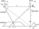
步骤5:读取最终相位图像中各像素点对应的最终相位值,依据经典光栅投影测量系统原理可求得被测物体的高度信息,从而实现三维信息的获取,经典光栅投影测量系统原理如图11所示,其中OP为投影装置镜头光心,又称投影中心,OP在参考面上的投影为O;图中的OXY平面为参考面,该面平行于投影面,Y轴平行于投影面上光栅条纹方向,原点O即OP在本面上的投影。Ωw为参考坐标系OXYZ,以参考面为本坐标系的OXY平面;Ωc为摄像机坐标系OcXcYcZc,原点Oc位于镜头光心;Zc位于光轴,Xc,Yc分别平行于摄像机成像面的横轴,纵轴;OcOP连线平行于参考面。Oc在参考面上的投影为O′c;d为投影中心OP到摄像机光心Oc之间距离;l为OP到参考面之间距离;P为物点,在参考面上的投影为P′。Step 5: Read the final phase value corresponding to each pixel in the final phase image, and obtain the height information of the measured object according to the principle of the classic grating projection measurement system, so as to realize the acquisition of three-dimensional information. The principle of the classic grating projection measurement system is shown in the figure 11, whereOP is the optical center of the lens of the projection device, also known as the projection center, and the projection ofOP on the reference plane is O; the OXY plane in the figure is the reference plane, which is parallel to the projection plane, and the Y axis is parallel to The direction of the grating stripes on the projection surface, the origin O is the projection ofOP on this surface. Ωw is the reference coordinate system OXYZ, and the reference plane is the OXY plane of this coordinate system; Ωc is the camera coordinate system Oc Xc Yc Zc , the origin Oc is located at the optical center of the lens; Zc is located on the optical axis, and Xc , Yc are parallel to the horizontal axis and vertical axis of the imaging plane of the camera respectively; the connecting line Oc OP is parallel to the reference plane. The projection of Oc on the reference plane is O′c ; d is the distance between the projection centerOP and the camera optical center Oc ; l is the distance betweenOP and the reference plane; P is the object point, The projection is P'.
投影装置和参考面的位置关系满足:参考面OXY平行于投影面,其Y轴平行于光栅条纹,原点O即投影中心OP在本面上的投影。The positional relationship between the projection device and the reference plane satisfies: the reference plane OXY is parallel to the projection plane, its Y axis is parallel to the grating stripes, and the origin O is the projection of the projection centerOP on this plane.
所以△BPP′∽△BOPO,So △BPP′∽△BOP O,
由于参考面OXY平行于投影面,Y轴平行于光栅方向,所以参考面上相位沿着X轴的方向变化。即:对OXY面上任一点(X,Y),设其相位为θ,有:Since the reference plane OXY is parallel to the projection plane, and the Y axis is parallel to the grating direction, the phase on the reference plane changes along the direction of the X axis. That is: for any point (X, Y) on the OXY surface, let its phase be θ, then:
式中θo为原点O的相位,λ0为光栅节距,即参考面上,沿X轴,相位变化1周期(2π)对应的长度。In the formula, θo is the phase of the origin O, and λ0 is the grating pitch, that is, the length corresponding to the phase change of one cycle (2π) along the X axis on the reference plane.
摄像机和参考面位置关系满足:The positional relationship between the camera and the reference surface satisfies:
1)即摄像机的Y轴平行于参考面的Y轴2)摄像机光心与投影中心连线平行于参考面。所以,有△APP′∽△AOcO′c,1) That is, the Y axis of the camera is parallel to the Y axis of the reference plane. 2) The line connecting the optical center of the camera and the projection center is parallel to the reference plane. Therefore, there is △APP′∽∽AOc O′c ,
(11),(13)联立,得(11), (13) combined, get
(14)式中l,d为系统参量。由(9),(14) where l and d are system parameters. By (9),
式中λ0为光栅节距,通过标定获得。θA、θB分别为A、B点的相位值。In the formula, λ0 is the grating pitch, which is obtained through calibration. θA , θB are the phase values of points A and B respectively.
(15)代入(14),整理,得:(15) Substitute into (14), sort out, get:
PP′即为被测物体的高度信息,最终三维重构效果参见附图12和图13。PP' is the height information of the measured object, and the final three-dimensional reconstruction effect is shown in Figure 12 and Figure 13.
Claims (2)


Priority Applications (1)
| Application Number | Priority Date | Filing Date | Title |
|---|---|---|---|
| CN201110366865.6ACN102519394B (en) | 2011-11-18 | 2011-11-18 | High-adaptability three-dimensional measuring method based on color structured light |
Applications Claiming Priority (1)
| Application Number | Priority Date | Filing Date | Title |
|---|---|---|---|
| CN201110366865.6ACN102519394B (en) | 2011-11-18 | 2011-11-18 | High-adaptability three-dimensional measuring method based on color structured light |
Publications (2)
| Publication Number | Publication Date |
|---|---|
| CN102519394A CN102519394A (en) | 2012-06-27 |
| CN102519394Btrue CN102519394B (en) | 2014-04-16 |
Family
ID=46290398
Family Applications (1)
| Application Number | Title | Priority Date | Filing Date |
|---|---|---|---|
| CN201110366865.6AExpired - Fee RelatedCN102519394B (en) | 2011-11-18 | 2011-11-18 | High-adaptability three-dimensional measuring method based on color structured light |
Country Status (1)
| Country | Link |
|---|---|
| CN (1) | CN102519394B (en) |
Families Citing this family (28)
| Publication number | Priority date | Publication date | Assignee | Title |
|---|---|---|---|---|
| CN103049731B (en)* | 2013-01-04 | 2015-06-03 | 中国人民解放军信息工程大学 | Decoding method for point-distributed color coding marks |
| CN103033171B (en)* | 2013-01-04 | 2014-10-29 | 中国人民解放军信息工程大学 | Encoding mark based on colors and structural features |
| CN103453852B (en)* | 2013-09-08 | 2016-01-13 | 西安电子科技大学 | Fast phase method of deploying in 3 D scanning system |
| CN103438833B (en)* | 2013-09-12 | 2016-01-20 | 香港应用科技研究院有限公司 | Optical method and system for three-dimensional shape measurement |
| CN104511905A (en)* | 2013-09-28 | 2015-04-15 | 沈阳新松机器人自动化股份有限公司 | Robot visual servo control method based on structured light |
| CN106537252B (en)* | 2014-05-06 | 2020-03-06 | 宁波舜宇光电信息有限公司 | Light transfer three-dimensional imaging device and projection device and their application |
| CN103954239A (en)* | 2014-05-08 | 2014-07-30 | 青岛三友智控科技有限公司 | Three-dimensional measurement system and method |
| DE102015208087A1 (en)* | 2015-04-30 | 2016-11-03 | Carl Zeiss Microscopy Gmbh | Method for generating a reflection-reduced contrast image and related devices |
| CN105719318B (en)* | 2016-01-26 | 2018-07-10 | 上海葡萄纬度科技有限公司 | Magic square color identification method based on HSV in a kind of Educational toy external member |
| CN106530344B (en)* | 2016-11-04 | 2019-07-26 | 四川大学 | Single-line structured light decoding method and system |
| CN106767526A (en)* | 2016-12-07 | 2017-05-31 | 西安知象光电科技有限公司 | A kind of colored multi-thread 3-d laser measurement method based on the projection of laser MEMS galvanometers |
| CN107068017A (en)* | 2017-03-10 | 2017-08-18 | 长春中国光学科学技术馆 | Adaptive projection demonstration device |
| CN107798698B (en)* | 2017-09-25 | 2020-10-27 | 西安交通大学 | Structured light stripe center extraction method based on gray correction and adaptive threshold |
| CN108931209B (en)* | 2018-05-04 | 2019-12-31 | 长春理工大学 | A Highly Adaptable 3D Reconstruction Method for Color Objects |
| CN108645354B (en)* | 2018-07-06 | 2019-10-18 | 四川大学 | Structured light three-dimensional imaging method and system for highly reflective object surface |
| CN109341548B (en)* | 2018-12-21 | 2020-08-11 | 福州大学 | Three-dimensional vibration vision measurement system and method based on variable density stripes |
| CN110160624B (en)* | 2019-05-13 | 2021-01-12 | 中国计量大学 | Optical fiber point diffraction device for three-dimensional vibration measurement and measurement method |
| CN110428459B (en)* | 2019-06-04 | 2023-05-16 | 重庆大学 | Digital sequential coding-based phase unwrapping method |
| CN110332895B (en)* | 2019-07-11 | 2021-07-02 | 广东工业大学 | A method, system and device for detecting the length and width information of a cuboid package |
| CN110332907B (en)* | 2019-08-19 | 2021-04-13 | 珠海博明视觉科技有限公司 | Method for improving surface stripe light reconstruction precision |
| CN111174731B (en)* | 2020-02-24 | 2021-06-08 | 五邑大学 | Method and device for double fringe projection phase unwrapping based on color segmentation |
| CN112697071B (en)* | 2020-11-17 | 2022-05-13 | 广东工业大学 | Three-dimensional measurement method for color structured light projection based on DenseNet shadow compensation |
| CN112781522A (en)* | 2020-12-25 | 2021-05-11 | 复旦大学 | Remove highlight contourgraph based on colored phase shift structured light |
| CN114688994B (en)* | 2020-12-31 | 2023-03-14 | 先临三维科技股份有限公司 | Color projection module, stripe decoding method, device, medium, equipment and system |
| CN114754703B (en)* | 2022-04-19 | 2024-04-19 | 安徽大学 | A three-dimensional measurement method and system based on color grating |
| CN114543707A (en)* | 2022-04-25 | 2022-05-27 | 南京南暄禾雅科技有限公司 | Phase expansion method in scene with large depth of field |
| TWI803369B (en)* | 2022-06-24 | 2023-05-21 | 寶成工業股份有限公司 | Automatic Mold Spraying System |
| CN116596772B (en)* | 2023-03-31 | 2025-06-06 | 资阳联耀医疗器械有限责任公司 | A method and system for generating color images based on grayscale image sensor |
Citations (1)
| Publication number | Priority date | Publication date | Assignee | Title |
|---|---|---|---|---|
| CN101975558A (en)* | 2010-09-03 | 2011-02-16 | 东南大学 | Rapid three-dimensional measurement method based on color grating projection |
Family Cites Families (2)
| Publication number | Priority date | Publication date | Assignee | Title |
|---|---|---|---|---|
| CA2435935A1 (en)* | 2003-07-24 | 2005-01-24 | Guylain Lemelin | Optical 3d digitizer with enlarged non-ambiguity zone |
| JP5055191B2 (en)* | 2008-04-24 | 2012-10-24 | パナソニック株式会社 | Three-dimensional shape measuring method and apparatus |
- 2011
- 2011-11-18CNCN201110366865.6Apatent/CN102519394B/ennot_activeExpired - Fee Related
Patent Citations (1)
| Publication number | Priority date | Publication date | Assignee | Title |
|---|---|---|---|---|
| CN101975558A (en)* | 2010-09-03 | 2011-02-16 | 东南大学 | Rapid three-dimensional measurement method based on color grating projection |
Non-Patent Citations (5)
| Title |
|---|
| A novel fringe adaptation method for digital projector;Shaoyan Gai,et al;《Optics and Lasers in Engineering》;20110113;547-552* |
| JP特开2009-264862A 2009.11.12 |
| Shaoyan Gai,et al.A novel fringe adaptation method for digital projector.《Optics and Lasers in Engineering》.2011,547-552. |
| 基于格雷编码的彩色结构光快速三维测量技术;韩佩妤 等;《光电子.激光》;20100930;第21卷(第9期);1359-1363* |
| 韩佩妤 等.基于格雷编码的彩色结构光快速三维测量技术.《光电子.激光》.2010,第21卷(第9期),1359-1363. |
Also Published As
| Publication number | Publication date |
|---|---|
| CN102519394A (en) | 2012-06-27 |
Similar Documents
| Publication | Publication Date | Title |
|---|---|---|
| CN102519394B (en) | High-adaptability three-dimensional measuring method based on color structured light | |
| CN101975558B (en) | Rapid three-dimensional measurement method based on color grating projection | |
| CN101813461B (en) | Absolute phase measurement method based on composite color fringe projection | |
| CN104390607B (en) | Phase encoding-based colorful structured light rapid three-dimensional measurement method | |
| CN100443854C (en) | Phase Unwrapping Method Based on Gray Code in 3D Scanning System | |
| CN101608906B (en) | Method for measuring optical three-dimensional contour of space coding | |
| CN101871773B (en) | Synchronous hue phase shift conversion method and three-dimensional morphology measurement system thereof | |
| CN105046743A (en) | Super-high-resolution three dimensional reconstruction method based on global variation technology | |
| CN105844633B (en) | Single frames structure optical depth acquisition methods based on De sequence and phase code | |
| CN102519395B (en) | Color response calibration method in colored structure light three-dimensional measurement | |
| CN108592822A (en) | A kind of measuring system and method based on binocular camera and structure light encoding and decoding | |
| CN101509763A (en) | Single order high precision large-sized object three-dimensional digitized measurement system and measurement method thereof | |
| CN101986098A (en) | Tricolor raster projection-based Fourier transform three-dimensional measuring method | |
| Song et al. | Super-resolution phase retrieval network for single-pattern structured light 3D imaging | |
| CN201218726Y (en) | 3D Reconstruction Device of Cultural Relics Based on Color Structured Light | |
| US9459094B2 (en) | Color-encoded fringe pattern for three-dimensional shape measurement | |
| CN102155924A (en) | Four-step phase shifting method based on absolute phase recovery | |
| CN101504277A (en) | Method for acquiring object three-dimensional image by optical three-dimensional sensing | |
| CN108592823A (en) | A kind of coding/decoding method based on binocular vision color fringe coding | |
| CN103292733B (en) | A kind of corresponding point lookup method based on phase shift and trifocal tensor | |
| CN109945802A (en) | A kind of structural light three-dimensional measurement method | |
| CN102243103A (en) | Method for quickly measuring colors and three-dimensional profile of object | |
| CN105069789A (en) | Structured light dynamic scene depth acquiring method based on encoding network template | |
| CN117073580B (en) | A microscopic dynamic three-dimensional measurement system and calibration method based on optical path optimization | |
| CN109631798A (en) | A kind of 3 d shape vertical measurement method based on π phase shifting method |
Legal Events
| Date | Code | Title | Description |
|---|---|---|---|
| C06 | Publication | ||
| PB01 | Publication | ||
| C10 | Entry into substantive examination | ||
| SE01 | Entry into force of request for substantive examination | ||
| C53 | Correction of patent for invention or patent application | ||
| CB02 | Change of applicant information | Address after:211300 Gaochun County of Jiangsu Province Economic Development Zone Branch Center Building Room 405 Applicant after:Southeast University Address before:211189 Jiangsu Road, Jiangning Development Zone, Southeast University, No. 2, No. Applicant before:Southeast University | |
| C14 | Grant of patent or utility model | ||
| GR01 | Patent grant | ||
| CF01 | Termination of patent right due to non-payment of annual fee | Granted publication date:20140416 Termination date:20161118 | |
| CF01 | Termination of patent right due to non-payment of annual fee |