CN102508088A - Checking instrument of backup automatic switching device - Google Patents
Checking instrument of backup automatic switching deviceDownload PDFInfo
- Publication number
- CN102508088A CN102508088ACN201110446933XACN201110446933ACN102508088ACN 102508088 ACN102508088 ACN 102508088ACN 201110446933X ACN201110446933X ACN 201110446933XACN 201110446933 ACN201110446933 ACN 201110446933ACN 102508088 ACN102508088 ACN 102508088A
- Authority
- CN
- China
- Prior art keywords
- plate
- pad
- backplate
- hole
- reason line
- Prior art date
- Legal status (The legal status is an assumption and is not a legal conclusion. Google has not performed a legal analysis and makes no representation as to the accuracy of the status listed.)
- Granted
Links
Images


Landscapes
- Train Traffic Observation, Control, And Security (AREA)
- Patch Boards (AREA)
Abstract
Description
Translated fromChinese技术领域technical field
本发明涉及一种超高压输变电行业中使用的备自投装置校验仪。 The invention relates to a calibrator for a backup automatic switching device used in the ultra-high voltage power transmission and transformation industry. the
背景技术Background technique
超高压输电行业中常用的备自投校验仪在使用过程中存在以下不足,第一,现有校验仪的操作面板是敞形式结构,面板上无任何保护装置,面板上的接线通、指示灯和其他操作装置外露,易受外界损害,使用寿命较短,并且,易引起误操作,也不方便携带;第二,现有的校验仪缺少支架,操作面板较低,不易于操作人员观察插孔和指示灯,易将导线接错,然而,为此外加支架,则又会增加校验仪的重量和体积,进一步增加了携带和使用的难度。 There are the following deficiencies in the use of the standby self-switching calibrator commonly used in the ultra-high voltage power transmission industry. First, the operation panel of the existing calibrator is an open structure, and there is no protective device on the panel. The wiring on the panel is connected, The indicator lights and other operating devices are exposed, which are easily damaged by the outside world, have a short service life, and are easy to cause misoperation and are not convenient to carry; secondly, the existing calibrator lacks a bracket, and the operation panel is low, so it is not easy to operate Personnel observe the socket and indicator light, and it is easy to connect the wrong wires. However, adding a bracket for this will increase the weight and volume of the calibrator, further increasing the difficulty of carrying and using. the
发明内容Contents of the invention
本发明的目的,是提供一种备自投装置校验仪,它在非使用状态下处于闭合状态,面板内藏,可得到有效的保护,携带较为方便;在使用状态下,面板的防护板打开变为支架,面板外露,方便操作人员观察和操作,从而可解决现有技术存在的问题。The object of the present invention is to provide a calibrator for self-injection equipment, which is in a closed state in a non-use state, with a built-in panel for effective protection and convenient portability; in use, the protective plate of the panel Opening becomes a bracket, and the panel is exposed, which is convenient for operators to observe and operate, thereby solving the problems existing in the prior art.
本发明的目的是通过以下技术方案实现的:备自投装置校验仪,包括备自投装置校验仪主机,备自投装置校验仪主机的面板两侧设有右滑轨和左滑轨,右滑轨内活动安装右滑块,左滑轨内活动安装左滑块,右滑块和左滑块分别与前护板固定连接;备自投装置校验仪主机左右两端各设有一根转轴,备自投装置校验仪主机的左右两端分别安装左护板和右护板,左护板和右护板分别通过一根转轴与备自投装置校验仪主机活动连接;右护板前侧与右支撑板铰接,左护板前侧与左支撑板铰接;右支撑板的上端与右护板的上端共面,右支撑板的下端高于右护板的下端,左支撑板的上端与左护板的上端共面,左支撑板的下端高于左护板的下端,右支撑板和左支撑板的高度相等,右支撑板和左支撑板的高度相等;前护板的右侧设有右定位套,右定位套的侧壁上开设锁定孔;右支撑板上安装右定位装置,右定位装置由手柄、轴、扭簧、连杆和定位块连接构成,右支撑板上开设支撑板通孔,支撑板通孔内安装轴,轴上安装连杆,连杆可在支撑板通孔上下摆动,轴的外周安装扭簧,扭簧的一端与右支撑板连接,扭簧的另一端与连杆连接,连杆的一端位于支撑板通孔内侧设有定位块,定位块与锁定孔配合,连杆的另一端位于支撑板通孔外侧安装手柄。The object of the present invention is achieved through the following technical solutions: the calibrator of the equipment for self-injection, including the host of the calibrator for the equipment for auto-injection; The right slider is installed in the right slide rail, and the left slider is installed in the left slide rail. The right slider and the left slider are respectively fixedly connected with the front guard plate; There is a rotating shaft, and the left and right guard plates are respectively installed at the left and right ends of the calibrator host of the standby self-injection device. The front side of the right guard plate is hinged with the right support plate, the front side of the left guard plate is hinged with the left support plate; the upper end of the right support plate is coplanar with the upper end of the right guard plate, the lower end of the right support plate is higher than the lower end of the right guard plate, The upper end of the upper end of the left guard plate is coplanar with the upper end of the left guard plate, the lower end of the left support plate is higher than the lower end of the left guard plate, the heights of the right support plate and the left support plate are equal, and the heights of the right support plate and the left support plate are equal; the front guard plate The right positioning sleeve is provided on the right side, and a locking hole is opened on the side wall of the right positioning sleeve; the right positioning device is installed on the right support plate, and the right positioning device is composed of a handle, a shaft, a torsion spring, a connecting rod and a positioning block, and the right support plate A support plate through hole is opened on the support plate, a shaft is installed in the support plate through hole, and a connecting rod is installed on the shaft. The connecting rod can swing up and down in the support plate through hole, and a torsion spring is installed on the outer periphery of the shaft. The other end of spring is connected with connecting rod, and one end of connecting rod is positioned at the inboard of support plate through hole and is provided with positioning block, and positioning block cooperates with locking hole, and the other end of connecting rod is positioned at the outside of support plate through hole and installs handle.
为进一步实现本发明的目的,还可以采用以下技术方案实现:所述前护板上开设数个前护板挂孔,备自投装置校验仪主机的顶部开设凹槽和理线板右滑道,理线板右滑道与凹槽相通;理线板右滑道内安装导杆,导杆上活动安装导向套,导向套通过铰链座与L形理线板的弯折处铰接,L形理线板的一侧上设有数个理线齿,理线齿的前端设有滑轨,滑轨上活动安装滑套,滑套的长度大于相邻两理线齿之间的间距,理线齿与前护板挂孔一一对应。所述备自投装置校验仪主机的顶部开设理线板左滑道,理线板左滑道与凹槽相通,且理线板右滑道与理线板左滑道平行。所述凹槽内安装右固定柱和左固定柱,L形理线板上设有右定位孔和左定位孔,右定位孔与右固定柱对应,左定位孔和左固定柱对应。所述右护板上开设护板通孔,右护板上安装右锁紧装置,右锁紧装置由锁紧装置壳体、右锁紧杆和弹簧连接构成,锁紧装置壳体与右护板固定连接,护板通孔内安装右锁紧杆,右锁紧杆的一端穿出锁紧装置壳体外设有拉手,右锁紧杆上设有杆限位块,右锁紧杆的外周安装弹簧,弹簧和杆限位块位于锁紧装置壳体内,弹簧位于杆限位块与锁紧装置壳体之间。所述备自投装置校验仪主机的右端水平设有第二限位块和第一限位块,第二限位块和第一限位块分别位于转轴的两侧;右护板上设有转动套,转动套与转轴配合,转动套设有限位板,限位板与第一限位块和第二限位块对应。In order to further realize the object of the present invention, the following technical solutions can also be adopted: several front guard plate hanging holes are provided on the front guard plate, grooves are provided on the top of the main body of the self-injection device calibrator and the cable management plate slides to the right The right slideway of the cable management board communicates with the groove; the guide rod is installed in the right slideway of the cable management board, and the guide sleeve is movably installed on the guide rod. The guide sleeve is hinged with the bending part of the L-shaped cable management board through the hinge seat, and the L-shaped There are several wire management teeth on one side of the wire management board. The front end of the wire management teeth is provided with a slide rail, and a sliding sleeve is movably installed on the slide rail. The length of the slide sleeve is greater than the distance between two adjacent wire management teeth. The teeth correspond to the hanging holes of the front guard plate one by one. The top of the main body of the self-injection device calibrator is provided with a left slideway of the wire management board, the left slideway of the wire management board communicates with the groove, and the right slideway of the wire management board is parallel to the left slideway of the wire management board. Right fixed column and left fixed column are installed in the described groove, and L shape line board is provided with right positioning hole and left positioning hole, and right positioning hole is corresponding with right fixed column, and left positioning hole is corresponding with left fixed column. A guard plate through hole is set on the right guard plate, and a right locking device is installed on the right guard plate. The right locking device is composed of a locking device housing, a right locking rod and a spring connection. The board is fixedly connected, and the right locking rod is installed in the through hole of the guard plate. One end of the right locking rod passes through the housing of the locking device and a handle is provided outside the housing. The right locking rod is provided with a rod limiter. The spring is installed, the spring and the rod limit block are located in the housing of the locking device, and the spring is located between the rod limit block and the housing of the locking device. The right end of the main body of the self-injection device calibrator is horizontally provided with a second limit block and a first limit block, and the second limit block and the first limit block are respectively located on both sides of the rotating shaft; There is a rotating sleeve, which cooperates with the rotating shaft, and the rotating sleeve is provided with a limit plate, which corresponds to the first limit block and the second limit block.
本发明的积极效果在于:它装有由前护板、右护板、左护板、右支撑板和左支撑板连接构成的同时具有保护面板和支架功能的装置,可根据用户的需要在闭合保护面板和打开支撑备自投装置校验仪主机的两状态下自由转换,可提高操作的精度和速度,可满足用户的使用需求。它还具有结构简洁紧凑、制造成本低廉和使用简便的优点。The positive effect of the present invention is that it is equipped with a device which is composed of a front guard plate, a right guard plate, a left guard plate, a right support plate and a left support plate, and has the functions of a protective panel and a bracket. The two states of the protective panel and the main body of the calibrator of the self-injection device with open support can be freely switched, which can improve the accuracy and speed of operation and meet the needs of users. It also has the advantages of simple and compact structure, low manufacturing cost and easy use.
附图说明Description of drawings
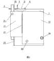
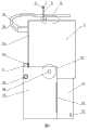
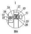
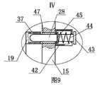
图1是本发明所述备自投装置校验仪的结构示意图;图2是图1的右视结构示意图;图3是图1的俯视结构示意图;图4是所述备自投装置校验仪打开后的结构示意图;图5是图4的右视结构示意图;图6是图1的Ⅰ局部放大结构示意图;图7是图2的II局部放大结构示意图;图8是图3的III局部放大结构示意图;图9是图4的Ⅳ局部放大结构示意图;图10是图5的Ⅴ局部放大结构示意图;图11是图5的Ⅵ局部放大结构示意图;图12是所述校验仪的备自动投跳合闸重动回路的原理图,图中AR为备自投合闸接点,KOM为备自投跳闸接点,KC为合闸重动中间继电器,KCO为分闸重动中间继电器;图13是所述校验仪的模拟断路器和电流、电压切换电路图。Fig. 1 is a schematic structural view of the calibrator of the automatic switching device of the present invention; Fig. 2 is a schematic view of the right view of Fig. 1; Fig. 3 is a schematic view of the top view of Fig. 1; Fig. 4 is a verification of the automatic switching device of the device Figure 5 is a schematic diagram of the structure of the right view of Figure 4; Figure 6 is a schematic diagram of the enlarged structure of the I part of Figure 1; Figure 7 is a schematic diagram of the enlarged structure of the II part of Figure 2; Figure 8 is a schematic diagram of the III part of Figure 3 Fig. 9 is a schematic diagram of a partial enlarged structure of IV of Fig. 4; Fig. 10 is a schematic diagram of a partial enlarged structure of Fig. 5 of V; Fig. 11 is a schematic diagram of a partial enlarged structure of Fig. 5 of VI; Fig. 12 is a spare Schematic diagram of the automatic switching and closing reset circuit, AR in the figure is the closing contact of the standby automatic switching, KOM is the tripping contact of the standby automatic switching, KC is the closing reset intermediate relay, and KCO is the opening reset intermediate relay; Figure 13 It is the analog circuit breaker and current and voltage switching circuit diagram of the calibrator.
附图标记:1备自投装置校验仪主机 2前护板 3滑套 4前护板挂孔 5L形理线板 6右固定柱 7滑轨 8理线齿 9理线板右滑道 10理线板左滑道 11左固定柱 12右定位孔 13左定位孔 14铰链座 15右护板 16左护板 17右支撑板 18左支撑板 19右定位套 20左定位套 21右定位装置 22左定位装置 23右滑轨 24左滑轨 25右滑块 26左滑块 27合页 28右锁紧杆 29左锁紧杆 30右锁紧装置 31左锁紧装置 32插头 33接线 34插孔 35支撑板通孔 36扭簧 37锁定孔 38定位块 39连杆 40轴 41手柄 42锁紧装置壳体 43拉手 44弹簧 45杆限位块 46电源插座 47护板通孔 48转轴 49转动套 50第一限位块 51第二限位块 52限位板 53凹槽 54导向套 55导杆 56第一快开开关 57第二快开开关。Reference signs: 1 self-injection
具体实施方式Detailed ways
本发明所述的备自投装置校验仪,包括备自投装置校验仪主机(1),如图4所示,备自投装置校验仪主机(1)的面板上设有以下装置:电源插座(46)是装置电源接入的插头;第一快开开关(56),即快分开关QF1是双相开关,控制模拟断路器KM1和KM2的分合;第二快开开关(57),即快分开关QF2是单相开关,控制备用电源电压切换继电器KM2,保证备用电压送入备自投装置;HR1-HR8是模拟断路器的位置指示灯,指示灯通常采用发光二极管;插孔X1-X8为电压连接端子,通常该组插孔涂成红色;X9、X10为电流连接端子,X11-X19为模拟断路器状态输出端子,X20-X27为备自投装置跳合闸接点输入端子。备自投装置校验仪主机(1)的面板两侧设有右滑轨(23)和左滑轨(24),电源插座(46)、第一快开开关(56)、第二快开开关(57)、插孔X1-X8、X11-X19、X20-X27以及HR1-HR8均位于右滑轨(23)和左滑轨(24)之间。右滑轨(23)内活动安装右滑块(25),左滑轨(24)内活动安装左滑块(26),右滑块(25)和左滑块(26)分别与前护板(2)固定连接;右滑轨(23)和左滑轨(24)分别对右滑块(25)和左滑块(26)起限位作用,使右滑块(25)仅可相对右滑轨(23)竖向直线移动,左滑块(26)仅可相对左滑轨(24)竖向直线移动,右滑轨(23)、左滑轨(24)、右滑块(25)和左滑块(26)使前护板(2)仅可相对备自投装置校验仪主机(1)竖向直线移动。如图2、图5和图11所示,备自投装置校验仪主机(1)左右两端各设有一根转轴(48),备自投装置校验仪主机(1)的左右两端分别安装左护板(16)和右护板(15),左护板(16)和右护板(15)分别通过一根转轴(48)与备自投装置校验仪主机(1)活动连接,左护板(16)和右护板(15)各自绕对应的转轴(48)相对备自投装置校验仪主机(1)转动。右护板(15)前侧与右支撑板(17)铰接,左护板(16)前侧与左支撑板(18)铰接。如图2所示,右支撑板(17)与右护板(15)之间通过合页(27)铰接。右支撑板(17)的上端与右护板(15)的上端共面,右支撑板(17)的下端高于右护板(15)的下端,左支撑板(18)的上端与左护板(16)的上端共面,左支撑板(18)的下端高于左护板(16)的下端,右支撑板(17)和左支撑板(18)的高度相等,右支撑板(17)和左支撑板(18)的高度相等。如图9所示,前护板(2)的右侧设有右定位套(19),右定位套(19)的侧壁上开设锁定孔(37)。为防止闭合状态下,右支撑板(17)相对右护板(15)翻转,起不到保护备自投装置校验仪主机(1)的作用。如图1和图6所示,右支撑板(17)上安装右定位装置(21),右定位装置(21)由手柄(41)、轴(40)、扭簧(36)、连杆(39)和定位块(38)连接构成,右支撑板(17)上开设支撑板通孔(35),支撑板通孔(35)内安装轴(40),轴(40)上安装连杆(39),连杆(39)可在支撑板通孔(35)上下摆动,以便于实现定位块(38)与锁定孔(37)之间的插入和分离。轴(40)的外周安装扭簧(36),扭簧(36)的一端与右支撑板(17)连接,扭簧(36)的另一端与连杆(39)连接,连杆(39)的一端位于支撑板通孔(35)内侧设有定位块(38),定位块(38)与锁定孔(37)配合,连杆(39)的另一端位于支撑板通孔(35)外侧安装手柄(41)。右支撑板(17)通过右定位装置(21)和右定位套(19)与前护板(2)锁定为一体。同样,为使左支撑板(18)与前护板(2)锁定,前护板(2)的左侧设有左定位套(20),左支撑板(18)上安装有左定位装置(22),左定位套(20)与右定位套(19)的结构完全对称,左定位装置(22)与右定位装置(21)的结构完全对称,左支撑板(18)通过左定位套(20)和左定位装置(22)与前护板(2)锁定于一体。前护板(2)、右支撑板(17)和左支撑板(18)锁定后,右护板(15)和左护板(16)可防止前护板(2)相对备自投装置校验仪主机(1)向上移动。The calibrator of the standby self-injection device according to the present invention includes the main unit (1) of the calibrator of the standby self-injection device. As shown in FIG. : The power socket (46) is the plug for the power supply of the device; the first quick-open switch (56), that is, the quick-open switch QF1 is a two-phase switch, which controls the opening and closing of the analog circuit breaker KM1 and KM2; the second quick-open switch ( 57), that is, the quick opening switch QF2 is a single-phase switch, which controls the backup power supply voltage switching relay KM2 to ensure that the backup voltage is sent to the backup self-injection device; HR1-HR8 are the position indicator lights of the analog circuit breaker, and the indicator lights usually use light-emitting diodes; Jacks X1-X8 are voltage connection terminals, and usually this group of jacks is painted red; X9 and X10 are current connection terminals, X11-X19 are analog circuit breaker status output terminals, and X20-X27 are tripping and closing contact input terminals for standby self-transfer device . There are right sliding rail (23) and left sliding rail (24) on both sides of the panel of the calibrator host (1) of the self-injection device, the power socket (46), the first quick opening switch (56), the second quick opening The switch (57), jacks X1-X8, X11-X19, X20-X27 and HR1-HR8 are all located between the right slide rail (23) and the left slide rail (24). The right slide block (25) is movably installed in the right slide rail (23), the left slide block (26) is movably installed in the left slide rail (24), and the right slide block (25) and the left slide block (26) are connected with the front guard plate respectively (2) fixedly connected; the right slide rail (23) and the left slide rail (24) play a position-limiting effect on the right slide block (25) and the left slide block (26) respectively, so that the right slide block (25) can only be opposite to the right The slide rail (23) moves vertically in a straight line, the left slide block (26) can only move vertically in a straight line relative to the left slide rail (24), the right slide rail (23), the left slide rail (24), and the right slide block (25) and the left slider (26) make the front guard (2) only move vertically and linearly relative to the calibrator host (1) of the self-injection device. As shown in Fig. 2, Fig. 5 and Fig. 11, there is a rotating shaft (48) at the left and right ends of the calibrator host (1) of the self-injection device, and the left and right ends of the calibrator host (1) of the auto-injection device Install the left guard plate (16) and the right guard plate (15) respectively, and the left guard plate (16) and the right guard plate (15) respectively move with the main unit (1) of the calibrator of the standby self-injection device through a rotating shaft (48) Connected, the left guard (16) and the right guard (15) rotate around the corresponding rotating shaft (48) relative to the host (1) of the calibrator of the standby self-injection device. The front side of the right guard plate (15) is hinged with the right support plate (17), and the front side of the left guard plate (16) is hinged with the left support plate (18). As shown in Figure 2, the right support plate (17) and the right guard plate (15) are hinged through a hinge (27). The upper end of the right support plate (17) is coplanar with the upper end of the right guard plate (15), the lower end of the right support plate (17) is higher than the lower end of the right guard plate (15), and the upper end of the left support plate (18) is aligned with the left guard plate. The upper end of plate (16) is coplanar, and the lower end of left support plate (18) is higher than the lower end of left guard plate (16), and the height of right support plate (17) and left support plate (18) is equal, and right support plate (17) ) and the height of the left support plate (18) are equal. As shown in Figure 9, a right positioning sleeve (19) is provided on the right side of the front guard (2), and a locking hole (37) is provided on the side wall of the right positioning sleeve (19). In order to prevent the right support plate (17) from flipping relative to the right guard plate (15) in the closed state, it cannot protect the calibrator host (1) of the self-injection device. As shown in Figure 1 and Figure 6, the right positioning device (21) is installed on the right support plate (17), and the right positioning device (21) consists of a handle (41), a shaft (40), a torsion spring (36), a connecting rod ( 39) is connected with the positioning block (38), and the right support plate (17) is provided with a support plate through hole (35), and the shaft (40) is installed in the support plate through hole (35), and the connecting rod ( 39), the connecting rod (39) can swing up and down in the support plate through hole (35), so as to realize the insertion and separation between the positioning block (38) and the locking hole (37). The outer circumference of the shaft (40) is equipped with a torsion spring (36), one end of the torsion spring (36) is connected with the right support plate (17), the other end of the torsion spring (36) is connected with the connecting rod (39), and the connecting rod (39) One end of the connecting rod (39) is located on the inside of the through hole (35) of the support plate, and a positioning block (38) is provided. The positioning block (38) is matched with the locking hole (37), and the other end of the connecting rod (39) is installed handle (41). The right support plate (17) is locked as a whole with the front guard plate (2) through the right positioning device (21) and the right positioning sleeve (19). Similarly, in order to lock the left support plate (18) with the front guard plate (2), the left side of the front guard plate (2) is provided with a left positioning sleeve (20), and a left positioning device (20) is installed on the left support plate (18). 22), the structures of the left positioning sleeve (20) and the right positioning sleeve (19) are completely symmetrical, the structures of the left positioning device (22) and the right positioning device (21) are completely symmetrical, and the left support plate (18) passes through the left positioning sleeve ( 20) and the left positioning device (22) are locked together with the front guard (2). After the front guard plate (2), the right support plate (17) and the left support plate (18) are locked, the right guard plate (15) and the left guard plate (16) can prevent the front guard plate (2) from aligning with the standby self-injection device. The tester host (1) moves upwards.
使用时,先向下按动手柄(41),手柄(41)通过连杆(39)带动定位块(38)与锁定孔(37)分离,同时连杆(39)克服扭簧(36)的弹力,此时右支撑板(17)与前护板(2)之间解锁,按同样方法将左支撑板(18)与前护板(2)解锁;再如图4和图5所示,将右护板(15)和左护板(16)分别绕各自的转轴(48)相对备自投装置校验仪主机(1)旋转180度,使右护板(15)、左护板(16)、右支撑板(17)和左支撑板(18)的上端朝下与支撑平面接触,右护板(15)、左护板(16)、右支撑板(17)和左支撑板(18)的下端朝上;然后将右支撑板(17)和左支撑板(18)向内侧翻折一定角度,使右支撑板(17)和左支撑板(18)位于备自投装置校验仪主机(1)的底部,对备自投装置校验仪主机(1)起支撑作用;最后将前护板(2)相对备自投装置校验仪主机(1)向下拉动,使前护板(2)与支撑平面接触,如图4所示,将备自投装置校验仪主机(1)的面板外露。此时,所述校验仪处于打开状态,面板外露且被抬高,方便用户操作。When in use, first press the handle (41) downward, the handle (41) drives the positioning block (38) to separate from the locking hole (37) through the connecting rod (39), and at the same time the connecting rod (39) overcomes the pressure of the torsion spring (36) At this time, the right support plate (17) and the front guard plate (2) are unlocked, and the left support plate (18) and the front guard plate (2) are unlocked in the same way; as shown in Figure 4 and Figure 5, Rotate the right guard (15) and the left guard (16) around their respective rotating shafts (48) relative to the main unit (1) of the calibrator of the self-injection device by 180 degrees, so that the right guard (15), the left guard ( 16), the upper ends of the right support plate (17) and the left support plate (18) are in contact with the support plane downwards, the right guard plate (15), the left guard plate (16), the right support plate (17) and the left support plate ( 18) facing upwards; then turn the right support plate (17) and left support plate (18) to the inside at a certain angle, so that the right support plate (17) and left support plate (18) are located The bottom of the calibrator main body (1) of the standby auto-injection device plays a supporting role; finally, the front guard plate (2) is pulled down relative to the calibrator host (1) of the standby auto-injection device The guard plate (2) is in contact with the support plane, as shown in Figure 4, exposing the panel of the calibrator host (1) of the self-injection device. At this time, the calibrator is in an open state, and the panel is exposed and raised, which is convenient for users to operate.
为进一步将前护板(2)的位置锁定,使其在闭合装态可遮挡保护备自投装置校验仪主机(1)的面板,如图所述前护板(2)上开设数个前护板挂孔(4),备自投装置校验仪主机(1)的顶部开设凹槽(53)和理线板右滑道(9),理线板右滑道(9)与凹槽(53)相通;理线板右滑道(9)内安装导杆(55),导杆(55)上活动安装导向套(54),导向套(54)可相对导杆(55)滑动,如图7所示,导向套(54)通过铰链座(14)与L形理线板(5)的弯折处铰接,L形理线板(5)的一侧上设有数个理线齿(8),理线齿(8)的前端设有滑轨(7),滑轨(7)上活动安装滑套(3),滑套(3)可沿滑轨(7)左右移动,滑套(3)的长度大于相邻两理线齿(8)之间的间距,理线齿(8)与前护板挂孔(4)一一对应。两相邻的理线齿(8)之间构成一个理线槽。当校验仪处理闭合状态时,前护板(2)位于备自投装置校验仪主机(1)面板前部,理线齿(8)与前护板挂孔(4)一一对应配合,此时理线齿(8)处于水平状态,备自投装置校验仪主机(1)通过L形理线板(5)将前护板(2)的位置锁定,防止前护板(2)下移;当校验仪需打开时,先将L形理线板(5)向后拉动,直至导向套(54)移至理线板右滑道(9)的最后端,此时前护板(2)与L形理线板(5)分离;再向后转动L形理线板(5),使理线齿(8)向上竖起,L形理线板(5)的另一侧位于凹槽(53)内,此时L形理线板(5)处于理线状态。由于备自投装置校验仪主机(1)面板上可插接数十根导线,因此,可根据用户的操作习惯,如图4和图5所示,将线分组放置于不同的理线槽内。为防止导线由理线槽内脱出造成线路混乱。导线置于理线槽内后,可如图4所示,将滑套(3)平移,使滑套(3)同时与该理线槽的两个理线齿(8)上的滑轨(7)配合连接,从而将该理线槽闭合,确保导线无法脱出。In order to further lock the position of the front guard (2) so that it can cover the panel of the calibrator host (1) of the self-injection device calibrator in the closed state, there are several openings on the front guard (2) as shown in the figure. Hanging hole (4) on the front guard plate, a groove (53) and a right slideway (9) of the cable management board are provided on the top of the calibrator host (1) for the self-injection device, and the right slideway (9) of the cable management The grooves (53) are connected; the guide rod (55) is installed in the right slideway (9) of the cable management board, and the guide sleeve (54) is movably installed on the guide rod (55), and the guide sleeve (54) can slide relative to the guide rod (55) , as shown in Figure 7, the guide sleeve (54) is hinged to the bend of the L-shaped cable management plate (5) through the hinge seat (14), and several cable management plates (5) are provided on one side Teeth (8), the front ends of the wire management teeth (8) are provided with slide rails (7), slide sleeves (3) are movably installed on the slide rails (7), and slide sleeves (3) can move left and right along the slide rails (7). The length of the sliding sleeve (3) is greater than the distance between two adjacent wire management teeth (8), and the wire management teeth (8) are in one-to-one correspondence with the front guard plate hanging holes (4). A wire management slot is formed between two adjacent wire management teeth (8). When the calibrator handles the closed state, the front guard plate (2) is located at the front of the panel of the calibrator main unit (1) of the self-injection device, and the wire management teeth (8) correspond to the hanging holes (4) of the front guard plate one by one At this time, the wire management teeth (8) are in a horizontal state, and the main unit (1) of the self-injection device calibrator (1) locks the position of the front guard (2) through the L-shaped wire management plate (5) to prevent the front guard (2) ) to move down; when the calibrator needs to be opened, first pull the L-shaped cable management plate (5) backward until the guide sleeve (54) moves to the rear end of the right slideway (9) of the cable management plate. The protective plate (2) is separated from the L-shaped cable management plate (5); then turn the L-shaped cable management plate (5) backward to make the wire management teeth (8) stand up, and the other side of the L-shaped cable management plate (5) One side is located in the groove (53), and now the L-shaped cable management plate (5) is in the cable management state. Since dozens of wires can be plugged into the panel of the calibrator host (1) of the standby self-injection device, the wires can be grouped and placed in different cable management slots as shown in Figure 4 and Figure 5 according to the user's operating habits Inside. In order to prevent wires from protruding from the wire management slot and causing line confusion. After the wires are placed in the wire management groove, as shown in Figure 4, the sliding sleeve (3) can be moved in translation so that the sliding sleeve (3) is simultaneously connected with the slide rails on the two wire management teeth (8) of the wire management groove ( 7) Cooperate with the connection to close the cable management slot to ensure that the wire cannot come out.
由于L形理线板(5)较为狭长,因此,为使L形理线板(5)移动时左右两端同步,如图3所示,所述备自投装置校验仪主机(1)的顶部开设理线板左滑道(10),理线板左滑道(10)与凹槽(53)相通,且理线板右滑道(9)与理线板左滑道(10)平行,理线板左滑道(10)内安装有另一套导杆(55)、导向套(54)和铰链座(14)。Since the L-shaped cable management board (5) is narrow and long, in order to synchronize the left and right ends of the L-shaped cable management board (5) when it moves, as shown in Figure 3, the main unit (1) of the calibrator of the self-injection device The left slideway of the cable management board (10) is opened on the top of the top, the left slideway of the cable management board (10) communicates with the groove (53), and the right slideway of the cable management board (9) and the left slideway of the cable management board (10) Parallel, another set of guide rod (55), guide sleeve (54) and hinge seat (14) are installed in the left slideway (10) of the cable management board.
为方便L形理线板(5)翻转定位,如图1和图10所示,所述凹槽(53)内安装右固定柱(6)和左固定柱(11),L形理线板(5)上设有右定位孔(12)和左定位孔(13),右定位孔(12)与右固定柱(6)对应,左定位孔(13)和左固定柱(11)对应。In order to facilitate the flipping and positioning of the L-shaped cable management board (5), as shown in Figure 1 and Figure 10, the right fixing column (6) and the left fixing column (11) are installed in the groove (53), and the L-shaped cable management board (5) is provided with right locating hole (12) and left locating hole (13), and right locating hole (12) is corresponding with right fixed post (6), and left locating hole (13) is corresponding with left fixed post (11).
为使右护板(15)在翻转180度可与前护板(2)锁定,对备自投装置校验仪主机(1)起更稳定的支撑作用,如图4和图9所示,所述右护板(15)上开设护板通孔(47),右护板(15)上安装右锁紧装置(30),右锁紧装置(30)由锁紧装置壳体(42)、右锁紧杆(28)和弹簧(44)连接构成,锁紧装置壳体(42)与右护板(15)固定连接,护板通孔(47)内安装右锁紧杆(28),右锁紧杆(28)的一端穿出锁紧装置壳体(42)外设有拉手(43),右锁紧杆(28)上设有杆限位块(45),右锁紧杆(28)的外周安装弹簧(44),弹簧(44)和杆限位块(45)位于锁紧装置壳体(42)内,弹簧(44)位于杆限位块(45)与锁紧装置壳体(42)之间,为右锁紧杆(28)提供预紧力。当右护板(15)由图1所示的状态翻转180度后呈图5所示状态时,如图9所示,右锁紧杆(28)与右定位套(19)配合,将右护板(15)与前护板(2)锁定,从而使右护板(15)可给予备自投装置校验仪主机(1)更加稳固的支撑。同理,左护板(16)上可安装备自投装置校验仪主机(1),左锁紧装置(31)的结构与右锁紧装置(30)完全对称,左锁紧装置(31)的左锁紧杆(29)与左定位套(20)配合将左护板(16)和前护板(2)锁定,右护板(15)、左护板(16)和前护板(2)连接构更稳固的支架。需将校验仪恢复闭合状态时,可先向外拉动右锁紧杆(28)和左锁紧杆(29),使右护板(15)和左护板(16)分别与前护板(2)脱离,再转动右护板(15)和左护板(16)恢复闭合状态。In order to make the right guard plate (15) lock with the front guard plate (2) when turned over 180 degrees, and provide a more stable support for the calibrator host (1) of the self-injection device, as shown in Figure 4 and Figure 9, A guard plate through hole (47) is provided on the right guard plate (15), a right locking device (30) is installed on the right guard plate (15), and the right locking device (30) is controlled by the locking device housing (42) 1. The right locking lever (28) is connected with the spring (44), the locking device housing (42) is fixedly connected with the right guard (15), and the right locking lever (28) is installed in the through hole (47) of the guard , one end of the right locking rod (28) passes through the locking device housing (42) and is provided with a handle (43), and the right locking rod (28) is provided with a rod limit block (45), and the right locking rod Install the spring (44) on the outer circumference of (28), the spring (44) and the rod limit block (45) are located in the locking device housing (42), the spring (44) is located between the rod limit block (45) and the locking device Between the shells (42), provide pre-tightening force for the right locking lever (28). When the right guard plate (15) turns 180 degrees from the state shown in Fig. 1 to the state shown in Fig. 5, as shown in Fig. 9, the right locking lever (28) cooperates with the right positioning sleeve (19), and the right The guard plate (15) is locked with the front guard plate (2), so that the right guard plate (15) can give more stable support to the calibrator host (1) of the self-injection device. In the same way, the main unit (1) of the self-injection device calibrator can be installed on the left guard plate (16), the structure of the left locking device (31) is completely symmetrical with the right locking device (30), and the left locking device (31) ) with the left locking lever (29) and the left positioning sleeve (20) to lock the left guard (16) and the front guard (2), the right guard (15), the left guard (16) and the front guard (2) A more stable bracket for the connection structure. When the calibrator needs to be restored to the closed state, the right locking lever (28) and the left locking lever (29) can be pulled outward first, so that the right guard (15) and the left guard (16) are respectively in contact with the front guard. (2) Disengage, and then turn the right guard (15) and left guard (16) to restore the closed state.
为确保右护板(15)准确地定位,如图11所示,所述备自投装置校验仪主机(1)的右端水平设有第二限位块(51)和第一限位块(50),第二限位块(51)和第一限位块(50)分别位于转轴(48)的两侧;右护板(15)上设有转动套(49),转动套(49)与转轴(48)活动配合,转动套(49)设有限位板(52),限位板(52)与第一限位块(50)和第二限位块(51)对应。如图11所示,限位板(52)与第二限位块(51)配合,右护板(15)处于打开状态;当转动右护板(15),使限位板(52)与第一限位块(50)配合时,右护板(15)处于闭合状态。In order to ensure the accurate positioning of the right guard plate (15), as shown in Figure 11, the right end of the calibrator host (1) of the self-injection device is horizontally provided with a second limit block (51) and a first limit block (50), the second limit block (51) and the first limit block (50) are respectively located on both sides of the rotating shaft (48); the right guard plate (15) is provided with a rotating sleeve (49), and the rotating sleeve (49 ) is movably matched with the rotating shaft (48), the rotating sleeve (49) is provided with a limiting plate (52), and the limiting plate (52) corresponds to the first limiting block (50) and the second limiting block (51). As shown in Figure 11, the limit plate (52) cooperates with the second limit block (51), and the right guard plate (15) is in an open state; when the right guard plate (15) is turned, the limit plate (52) and When the first limit block (50) cooperates, the right guard plate (15) is in a closed state.
所述备自投装置校验仪主机(1)可与超高压行业现有的检验仪相同,也可以主要有三大部分组成:1、备自投装置跳合闸重动部分;2、模拟断路器和电压、电流切换部分3、控制、显示部分。The main unit (1) of the calibrator of the standby automatic switching device can be the same as the existing testing instrument in the ultra-high voltage industry, and can also mainly consist of three major parts: 1. The tripping and closing part of the standby automatic switching device; 2. Simulated open circuit Device and voltage, current switching
一、备自投装置跳合闸重动部分:1. The tripping and closing part of the standby automatic switching device:
由于备自投装置输出的接点容量不够,不能切断模拟断路器的回路电流,因此需要对备自投装置输出的接点进行重动以增加接点容量。结构图12和图13,简要介绍备自投装置跳合闸重动回路原理图:因为我们的备自投装置所连接的断路器有4台(工作电源的高压侧和低压侧开关,备用电源的高压侧和低压侧开关。),所以图12包括了4台开关的跳、合闸接点的重动回路。图12中KOM1和KOM2分别为备自投装置输出的跳开工作电源高压侧和低压侧开关跳闸接点,分别启动跳闸重动继电器KCO1和KCO2,然后跳开图13中的模拟断路器KM1和KM2。Since the output contact capacity of the standby automatic switching device is not enough to cut off the loop current of the simulated circuit breaker, it is necessary to reset the output contact of the standby automatic switching device to increase the contact capacity. Structural diagrams 12 and 13 briefly introduce the schematic diagram of the tripping, closing and resetting circuit of the standby automatic switching device: because there are 4 circuit breakers connected to our standby automatic switching device (high-voltage side and low-voltage side switches of the working power supply, backup power supply The high-voltage side and low-voltage side switches.), so Figure 12 includes the reset circuit of the tripping and closing contacts of the 4 switches. In Figure 12, KOM1 and KOM2 are respectively the trip contacts of the high-voltage side and low-voltage side switches of the working power supply output by the standby self-injection device, respectively start the trip reset relays KCO1 and KCO2, and then trip the analog circuit breakers KM1 and KM2 in Figure 13 .
二、模拟断路器和电压、电流切换部分:2. Analog circuit breaker and voltage and current switching part:
由于备自投装置动作需要一定的条件:1、充电条件:工作电源的三相电压为57.7V,一相电流有电流存在,并且高压侧和低压侧开关在合闸位置;2、动作条件:工作电源的高低压侧断路器因故障原因跳闸或开关偷跳,工作电源的电压、电流消失,并且备用电源电压正常。只有满足以上两个条件,备自投装置才能正确动作。为了满足备自投动作的两个条件,我们设计了模拟断路器和电压、电流、切换部分,原理如图13。原理介绍:①QF1为快分开关控制模拟断路器KM1和KM2合闸,当快分开关QF1合上时,模拟断路器KM1和KM2动作输出常开接点给备自投装置,模拟工作电源的高压侧和低压侧开关在合闸位置,同时利用KM1和KM2的辅助接点把工作电压和电流切换至备自投的电压、电流回路,模拟工作电源的正常运行状态,在这种状态下,备自投装置会延时充电。②充电完成后断开快分开关QF1,模拟断路器KM1和KM2因失电而跳开,因此备自投装置会失去工作电源的电压、电流和断路器的合闸位置接点,这样模拟断路器因故障原因跳闸或开关偷跳的状态。③由于的备自投的动作条件要求备用电源电压正常,因此设置备用电压切换继电器KM5,当合上快分开关QF2时,把电压切换至备自投装置,这样模拟备自投备用电压回路。④备自投装置在满足动作条件后正确动作,输出KC1和KC2合闸接点,合上备用电源模拟断路器KM3和KM4。通过以上介绍,模拟断路器和电压、电流、切换部分和备自投装置跳合闸重动部分相互配合能可靠校验“备自投装置”的动作逻辑,而无需停用一次设备。Certain conditions are required for the operation of the standby automatic switching device: 1. Charging conditions: the three-phase voltage of the working power supply is 57.7V, there is current in one phase current, and the high-voltage side and low-voltage side switches are in the closing position; 2. Operating conditions: The circuit breaker on the high and low voltage side of the working power supply trips or the switch slips due to a fault, the voltage and current of the working power supply disappear, and the voltage of the backup power supply is normal. Only when the above two conditions are met, the standby automatic switching device can operate correctly. In order to meet the two conditions of the standby automatic switching action, we designed the analog circuit breaker and the voltage, current, and switching parts. The principle is shown in Figure 13. Principle introduction: ① QF1 is a fast-opening switch that controls the closing of analog circuit breakers KM1 and KM2. When the quick-opening switch QF1 is closed, the analog circuit breakers KM1 and KM2 act to output normally open contacts to the backup self-switching device, simulating the high-voltage side of the working power supply And the low-voltage side switch is in the closing position, and at the same time, use the auxiliary contacts of KM1 and KM2 to switch the working voltage and current to the voltage and current loop of the standby self-injection, simulating the normal operating state of the working power supply. In this state, the standby self-injection The device will charge with a delay. ②Turn off the quick opening switch QF1 after the charging is completed, and the simulated circuit breaker KM1 and KM2 will trip due to power failure, so the standby self-switching device will lose the voltage and current of the working power supply and the closing position contact of the circuit breaker, thus simulating the circuit breaker The status of a trip or switch slipping due to a fault. ③Because the operation condition of standby automatic switching requires that the voltage of the standby power supply is normal, the standby voltage switching relay KM5 is set. When the quick release switch QF2 is closed, the voltage is switched to the standby automatic switching device, thus simulating the backup voltage circuit of standby automatic switching. ④ The standby self-switching device operates correctly after meeting the operating conditions, outputs the closing contacts of KC1 and KC2, and closes the analog circuit breakers KM3 and KM4 of the standby power supply. Through the above introduction, the cooperation between the simulated circuit breaker and the voltage, current, switching part and the tripping and resetting part of the standby automatic switching device can reliably verify the action logic of the "standby automatic switching device" without stopping the primary equipment.
三、 控制、显示部分3. Control and display part
控制、显示部分作用是:1、控制装置内部动作逻辑;2、与备自投装置的电流、电压和接点回路的连接;3、显示模拟断路器的状态;4、保证电源供给。The functions of the control and display part are: 1. The internal action logic of the control device; 2. The connection with the current, voltage and contact circuit of the standby automatic switching device; 3. Display the status of the analog circuit breaker; 4. Ensure the power supply.
本发明所述的技术方案并不限制于本发明所述的实施例的范围内。本发明未详尽描述的技术内容均为公知技术。 The technical solutions described in the present invention are not limited within the scope of the embodiments described in the present invention. The technical contents not described in detail in the present invention are all known technologies. the
Claims (6)
Priority Applications (1)
| Application Number | Priority Date | Filing Date | Title |
|---|---|---|---|
| CN201110446933.XACN102508088B (en) | 2011-12-28 | 2011-12-28 | Self-injection device calibrator |
Applications Claiming Priority (1)
| Application Number | Priority Date | Filing Date | Title |
|---|---|---|---|
| CN201110446933.XACN102508088B (en) | 2011-12-28 | 2011-12-28 | Self-injection device calibrator |
Publications (2)
| Publication Number | Publication Date |
|---|---|
| CN102508088Atrue CN102508088A (en) | 2012-06-20 |
| CN102508088B CN102508088B (en) | 2014-01-29 |
Family
ID=46220193
Family Applications (1)
| Application Number | Title | Priority Date | Filing Date |
|---|---|---|---|
| CN201110446933.XAExpired - Fee RelatedCN102508088B (en) | 2011-12-28 | 2011-12-28 | Self-injection device calibrator |
Country Status (1)
| Country | Link |
|---|---|
| CN (1) | CN102508088B (en) |
Cited By (3)
| Publication number | Priority date | Publication date | Assignee | Title |
|---|---|---|---|---|
| CN103633740A (en)* | 2013-11-29 | 2014-03-12 | 国家电网公司 | Monitoring device for telecontrol channel fault |
| CN112622459A (en)* | 2020-12-18 | 2021-04-09 | 贵州云侠科技有限公司 | Printer ribbon cartridge |
| CN114062719A (en)* | 2021-10-20 | 2022-02-18 | 深圳市圣格特电子有限公司 | Signal analysis meter signal anti-interference processing method and signal analysis meter |
Citations (4)
| Publication number | Priority date | Publication date | Assignee | Title |
|---|---|---|---|---|
| CN201251605Y (en)* | 2008-08-01 | 2009-06-03 | 江苏省电力公司宿迁供电公司 | Calibrator of automatic bus transfer device |
| CN101504449A (en)* | 2009-03-13 | 2009-08-12 | 江苏省电力公司常州供电公司 | Experiment tester for spare power automatic switching apparatus |
| CN201600418U (en)* | 2009-11-30 | 2010-10-06 | 山东电力集团公司超高压公司 | Relaying protection system tester |
| CN202649319U (en)* | 2011-12-28 | 2013-01-02 | 山东电力集团公司超高压公司 | Backup power automatic switching device calibrator |
- 2011
- 2011-12-28CNCN201110446933.XApatent/CN102508088B/ennot_activeExpired - Fee Related
Patent Citations (4)
| Publication number | Priority date | Publication date | Assignee | Title |
|---|---|---|---|---|
| CN201251605Y (en)* | 2008-08-01 | 2009-06-03 | 江苏省电力公司宿迁供电公司 | Calibrator of automatic bus transfer device |
| CN101504449A (en)* | 2009-03-13 | 2009-08-12 | 江苏省电力公司常州供电公司 | Experiment tester for spare power automatic switching apparatus |
| CN201600418U (en)* | 2009-11-30 | 2010-10-06 | 山东电力集团公司超高压公司 | Relaying protection system tester |
| CN202649319U (en)* | 2011-12-28 | 2013-01-02 | 山东电力集团公司超高压公司 | Backup power automatic switching device calibrator |
Cited By (3)
| Publication number | Priority date | Publication date | Assignee | Title |
|---|---|---|---|---|
| CN103633740A (en)* | 2013-11-29 | 2014-03-12 | 国家电网公司 | Monitoring device for telecontrol channel fault |
| CN112622459A (en)* | 2020-12-18 | 2021-04-09 | 贵州云侠科技有限公司 | Printer ribbon cartridge |
| CN114062719A (en)* | 2021-10-20 | 2022-02-18 | 深圳市圣格特电子有限公司 | Signal analysis meter signal anti-interference processing method and signal analysis meter |
Also Published As
| Publication number | Publication date |
|---|---|
| CN102508088B (en) | 2014-01-29 |
Similar Documents
| Publication | Publication Date | Title |
|---|---|---|
| CN103440803B (en) | The authentic training system of 10kV power distribution equipment real voltage analog current closed loop | |
| CN102508088B (en) | Self-injection device calibrator | |
| CN201956614U (en) | Novel power distribution box | |
| CN202649319U (en) | Backup power automatic switching device calibrator | |
| CN220652715U (en) | Special integrated contact side expansion mobile emergency power supply equipment | |
| CN103077631B (en) | Training device for three-phase circuit breaker spring operation mechanism | |
| CN202736378U (en) | Low-pressure fault elimination practical training device | |
| CN205983968U (en) | Analog circuit of this mimic -disconnecting switch screen is shielded and is used for to many functional simulation circuit breaker | |
| CN103746311A (en) | Drawer type low-voltage switch cabinet | |
| CN206323011U (en) | Protective cover is touched in anti-relay-protection pressing plate malfunction by mistake | |
| CN111668837A (en) | A bypass quick-cut switch and its non-power-off operation method | |
| CN209641125U (en) | Power cable simulation test device | |
| CN203747279U (en) | Drawer type low-voltage switch cabinet | |
| CN202906274U (en) | Drawer type intelligent circuit breaker | |
| CN217954588U (en) | A secondary operation auxiliary device for distribution network | |
| CN202103354U (en) | Handcart-type permanent magnet combination open circuit device | |
| CN205863677U (en) | High-tension switch cabinet on-line checking and display system | |
| CN205862633U (en) | A kind of Power system tranining device | |
| CN109164309A (en) | A kind of nuclear phase assisting device of high-tension switch cabinet | |
| CN115967165A (en) | A kind of control device and operation method for generator power keeping and non-stop operation | |
| CN208257244U (en) | The protection exclusive circuit and low-voltage distribution cabinet of electrically operated institution | |
| CN207380163U (en) | New collection terminal test bench | |
| CN209373076U (en) | A quick calibration device for automatic switching | |
| CN108832518B (en) | A 10kV switchgear nuclear phase handcart | |
| CN105243937A (en) | Substation operation physical simulation training screen |
Legal Events
| Date | Code | Title | Description |
|---|---|---|---|
| C06 | Publication | ||
| PB01 | Publication | ||
| C10 | Entry into substantive examination | ||
| SE01 | Entry into force of request for substantive examination | ||
| ASS | Succession or assignment of patent right | Owner name:STATE GRID SHANDONG ELECTRIC POWER COMPANY MAINTEN Effective date:20131121 Owner name:STATE ELECTRIC NET CROP. Free format text:FORMER OWNER: ULTRA-HV COMPANY OF SHANDONG ELECTRIC POWER CORPORATION Effective date:20131121 | |
| C41 | Transfer of patent application or patent right or utility model | ||
| COR | Change of bibliographic data | Free format text:CORRECT: ADDRESS; FROM: 250021 JINAN, SHANDONG PROVINCE TO: 100031 XICHENG, BEIJING | |
| TA01 | Transfer of patent application right | Effective date of registration:20131121 Address after:100031 Xicheng District West Chang'an Avenue, No. 86, Beijing Applicant after:State Grid Corporation of China Applicant after:MAINTENANCE COMPANY OF STATE GRID SHANDONG ELECTRIC POWER Co. Address before:250021 No. ten, No. 111, weft Road, Shandong, Ji'nan Applicant before:Extra-high Voltage Co., Ltd., Shandong Electric Power Corp. | |
| C14 | Grant of patent or utility model | ||
| GR01 | Patent grant | ||
| CF01 | Termination of patent right due to non-payment of annual fee | ||
| CF01 | Termination of patent right due to non-payment of annual fee | Granted publication date:20140129 |