CN102499674B - An EEG cap with a socket structure and multiple guaranteed contacts in close contact with the scalp - Google Patents
An EEG cap with a socket structure and multiple guaranteed contacts in close contact with the scalpDownload PDFInfo
- Publication number
- CN102499674B CN102499674BCN201110311884.9ACN201110311884ACN102499674BCN 102499674 BCN102499674 BCN 102499674BCN 201110311884 ACN201110311884 ACN 201110311884ACN 102499674 BCN102499674 BCN 102499674B
- Authority
- CN
- China
- Prior art keywords
- warp
- electrode
- pin
- main body
- eeg
- Prior art date
- Legal status (The legal status is an assumption and is not a legal conclusion. Google has not performed a legal analysis and makes no representation as to the accuracy of the status listed.)
- Expired - Fee Related
Links
- 210000004761scalpAnatomy0.000titleclaimsabstractdescription14
- 210000003128headAnatomy0.000claimsabstractdescription28
- 238000004070electrodepositionMethods0.000claimsabstractdescription5
- 210000005069earsAnatomy0.000claimsabstractdescription4
- 239000004744fabricSubstances0.000claimsabstractdescription4
- 210000004556brainAnatomy0.000claimsdescription9
- 230000005611electricityEffects0.000claimsdescription9
- RYGMFSIKBFXOCR-UHFFFAOYSA-NCopperChemical compound[Cu]RYGMFSIKBFXOCR-UHFFFAOYSA-N0.000claimsdescription3
- 229910052802copperInorganic materials0.000claimsdescription3
- 239000010949copperSubstances0.000claimsdescription3
- 239000000835fiberSubstances0.000claimsdescription3
- 239000000463materialSubstances0.000claimsdescription2
- 239000012634fragmentSubstances0.000claims9
- 239000000758substrateSubstances0.000claims3
- 230000000149penetrating effectEffects0.000claims2
- 238000002360preparation methodMethods0.000abstractdescription2
- 230000001054cortical effectEffects0.000description3
- 239000013013elastic materialSubstances0.000description3
- 238000002347injectionMethods0.000description3
- 239000007924injectionSubstances0.000description3
- 230000007812deficiencyEffects0.000description2
- 238000003745diagnosisMethods0.000description2
- 239000004033plasticSubstances0.000description2
- 229920000728polyesterPolymers0.000description2
- 239000004020conductorSubstances0.000description1
- 238000013480data collectionMethods0.000description1
- 238000013461designMethods0.000description1
- 238000011161developmentMethods0.000description1
- 238000010586diagramMethods0.000description1
- 206010015037epilepsyDiseases0.000description1
- 210000001061foreheadAnatomy0.000description1
- 238000003780insertionMethods0.000description1
- 230000037431insertionEffects0.000description1
- 238000000034methodMethods0.000description1
- 238000012545processingMethods0.000description1
- 238000011160researchMethods0.000description1
Images


Landscapes
- Measurement And Recording Of Electrical Phenomena And Electrical Characteristics Of The Living Body (AREA)
Abstract
Translated fromChineseDescription
Translated fromChinese技术领域technical field
本发明属于生物医学领域,具体涉及一种采用插座结构的多重保障触点紧密接触头皮的脑电帽。The invention belongs to the field of biomedicine, and in particular relates to an EEG cap which adopts a socket structure and has multiple guarantee contacts in close contact with the scalp.
背景技术Background technique
随着生物电子和计算机技术的发展,基于皮层脑电数据的应用研究取得了一些成果。例如基于脑电图的癫痫诊断,以及基于皮层脑电的想象运动等脑机接口应用。而目前脑电帽仍然是脑电采集装置的重要组成部分,其关系到皮层脑电数据的采集性能,将直接影响到后续的分析处理。With the development of bioelectronics and computer technology, some achievements have been made in the application research based on cortical EEG data. For example, epilepsy diagnosis based on EEG, and brain-computer interface applications such as brain-computer interface based on cortical EEG. At present, the EEG cap is still an important part of the EEG acquisition device, which is related to the acquisition performance of cortical EEG data and will directly affect the subsequent analysis and processing.
目前普遍使用的脑电帽分为两种:一种是弹性胶条网状脑电帽(91229754.9),如图1所示,这种脑电帽由弹性胶条网状结构构成。使用时,人要手动的将电极夹在脑电帽上。这种固定电极的方式使得电极位置偏差很大,很难将电极放置在准确的位置上,从而导致多导脑电采集的不准确。另外,在同一条弹性胶条上固定3个以上电极,或同一区域固定有多个电极时,由于头部的凸凹不平已经电极固定方向的不一致,很容易造成个别电极因周围电极将弹性胶条撑得离头皮过远而接触不到头皮的情况,从而导致采集数据的错误,并而最终导致诊断错误或分析错误。另一种脑电帽是应用导电膏导电的脑电帽,如Neroscan公司出产的脑电帽。这种脑电帽的电极按国际标准位置固定在弹性的帽子上,受试者带上这种帽子时,电极自动的按照国际标准位置分布在头部,但需要在电极处注入适量导电膏,使电极与头皮之间的阻抗达到预定值。因此使用时准备时间较长,并且导电膏的注入量很难控制,注入量过多时,导电膏与头皮接触面积过大,使得采集得到的信号中含有过多其他电极点信号的干扰;而注入量不够时,电极与头皮之间阻抗过高,将无法有效采集脑电信号。因此,设计新型的脑电帽以解决现有技术中的不足显得尤为重要。There are two types of EEG caps commonly used at present: one is the elastic strip mesh EEG cap (91229754.9), as shown in Figure 1, this EEG cap is composed of elastic strip mesh structure. During use, people will manually clamp the electrodes on the EEG cap. This way of fixing the electrodes makes the position of the electrodes deviate greatly, and it is difficult to place the electrodes in an accurate position, resulting in inaccurate acquisition of multi-conductor EEG. In addition, when more than 3 electrodes are fixed on the same elastic strip, or multiple electrodes are fixed in the same area, due to the unevenness of the head and the inconsistency of the electrode fixing direction, it is easy to cause individual electrodes to be deformed by the elastic strip due to the surrounding electrodes. The condition of propping too far away from the scalp to make contact with it, leading to errors in data collection and, ultimately, errors in diagnosis or analysis. Another kind of EEG cap is an EEG cap that uses conductive paste to conduct electricity, such as the EEG cap produced by Neroscan Corporation. The electrodes of this EEG cap are fixed on the elastic cap according to the international standard position. When the subject wears this cap, the electrodes are automatically distributed on the head according to the international standard position, but it is necessary to inject an appropriate amount of conductive paste into the electrode. Make the impedance between the electrode and the scalp reach a predetermined value. Therefore, it takes a long time to prepare for use, and it is difficult to control the injection amount of conductive paste. When the injection amount is too large, the contact area between the conductive paste and the scalp is too large, so that the collected signal contains too much interference from other electrode point signals; When the amount is not enough, the impedance between the electrodes and the scalp is too high, and the EEG signals cannot be collected effectively. Therefore, it is particularly important to design a novel EEG cap to solve the deficiencies in the prior art.
发明内容Contents of the invention
本发明的目的是针对现有技术的不足,提供一种用于脑电采集的脑电帽。The object of the present invention is to provide an EEG cap for EEG collection aiming at the deficiencies in the prior art.
本发明包括半球状脑电帽主体、按国际10-20系统中F3、F4、C3、C4、P3、P4、O1、O2电极位置固定在主体上的电极座、位于两侧耳下的经线固定锁、连接两侧经线固定锁的下颚固定带以及与电极座配合使用的电极销。主体由弹性面料构成。脑电帽内有经线,该经线的两端固定在脑电帽主体两边的经线固定锁上,且每条经线穿过两个在头部左右对应的电极座。其中经线为含涤纶纤维或橡胶的弹性绳。The present invention includes a hemispherical EEG cap main body, electrode holders fixed on the main body according to the F3, F4, C3, C4, P3, P4, O1, O2 electrode positions in the international 10-20 system, and warp thread fixing locks located under the ears on both sides. , the mandibular fixing belt connecting the warp fixing locks on both sides and the electrode pin used in conjunction with the electrode holder. The main body is constructed of stretch fabric. There are warps in the EEG cap, the two ends of which are fixed on the warp fixing locks on both sides of the EEG cap main body, and each warp passes through two corresponding electrode seats on the left and right sides of the head. Wherein the warp is an elastic rope containing polyester fiber or rubber.
电极座为圆柱型,母线长为CL,在轴心处沿轴线方向有一插孔,插孔包括一圆孔和一与圆孔相通的长方型孔,插孔沿轴线方向贯穿电极座。其中,圆孔的轴线与电极座的轴线共线。电极座在脑电帽内侧部分的有一经线孔,该经线孔轴线与电极座上下表面平行,不与插孔交叉且贯穿电极座。The electrode base is cylindrical, the length of the bus bar is CL, and there is a jack at the axis along the axial direction. The jack includes a round hole and a rectangular hole communicating with the round hole. Wherein, the axis of the circular hole is collinear with the axis of the electrode seat. The electrode seat has a meridian hole in the inner part of the EEG cap, the axis of the meridian hole is parallel to the upper and lower surfaces of the electrode seat, does not intersect with the socket and runs through the electrode seat.
电极销包括:竖直的圆柱型销身;固定在销身正上方的长方体销把;固定在销身正下方的电极触点;固定在销身侧面,且底端与销身低端相连的弹片组。其中销身母线长L,L=1.8CL。销把和电极触点的几何中心都在销身的中轴线上。销身和销把在中轴线上有一导线孔,导线孔贯穿销身与销把,导线通过导线孔连接至电极触点。弹片组包括基板、弹片、滚头及连接板。基板为水平的长方形板,其一边通过连接板与销身连接。弹片也是一长方形板,弹片的一边542a与基板中的边541a的临边重合。滚头为一圆柱型结构,固定在弹片边542a的对边,滚头母线与销身母线垂直,滚头的侧面与弹片相切。弹片组整体高度为h,h=CL。弹片组材料为弹性材料,如弹性塑料、薄铜片等。The electrode pin includes: a vertical cylindrical pin body; a rectangular parallelepiped pin handle fixed directly above the pin body; an electrode contact fixed directly below the pin body; shrapnel group. Among them, the length of the bus bar of the pin body is L, and L=1.8CL. The geometric centers of the pin handle and the electrode contacts are all on the central axis of the pin body. The pin body and the pin handle have a wire hole on the central axis, the wire hole runs through the pin body and the pin handle, and the wire is connected to the electrode contact through the wire hole. The shrapnel group includes base plate, shrapnel, roller head and connecting plate. The base plate is a horizontal rectangular plate, one side of which is connected to the pin body through a connecting plate. The elastic piece is also a rectangular plate, and one side 542a of the elastic piece coincides with the adjacent edge of the
经线固定锁为圆柱型,在经线固定锁的中轴线处有一穿过经线固定锁上下表面的矩形孔。在经线固定锁侧面有一经过其中轴线与矩形孔相交的圆孔。圆孔中轴线与经线固定锁上表面平行,且穿过经线固定锁。经线固定锁还包括一与其矩形孔大小形状均一致的固定锁孔塞。在经线穿过经线固定锁时,即可用固定锁孔塞塞入矩形孔 ,用摩擦力来固定经线。The warp fixed lock is cylindrical, and there is a rectangular hole passing through the upper and lower surfaces of the warp fixed lock at the central axis of the warp fixed lock. On the side of the warp fixed lock, there is a circular hole passing through the central axis and intersecting the rectangular hole. The central axis of the circular hole is parallel to the upper surface of the warp fixing lock and passes through the warp fixing lock. The warp fixed lock also includes a fixed keyhole plug that is consistent in size and shape with the rectangular hole. When the warp thread passes through the warp thread fixed lock, the fixed lock hole plug can be inserted into the rectangular hole to fix the warp thread with friction.
本发明相对于现有技术。具有以下优点:The present invention is relative to the prior art. Has the following advantages:
(1) 使用时操作简便,克服现有技术中应用导电膏的脑电帽操作繁琐的缺点,能够快速完成对脑电采集的准备工作。(1) It is easy to operate when used, overcomes the disadvantages of cumbersome operation of the EEG cap using conductive paste in the prior art, and can quickly complete the preparation for EEG acquisition.
(2) 电极定位准确,克服了现有技术中弹性胶条网状脑电帽定位不准的缺点,提高脑电采集准确度。(2) The electrode positioning is accurate, which overcomes the shortcomings of the inaccurate positioning of the elastic strip mesh EEG cap in the prior art, and improves the accuracy of EEG acquisition.
(3) 电极触点与头皮接触牢靠,避免了使用导电膏情形时,对注入量的要求;同时也避免了弹性胶条网状脑电帽中少数电极与头皮接触不良的偶发情况。(3) The electrode contacts are in firm contact with the scalp, which avoids the requirement for injection volume when using conductive paste; at the same time, it also avoids the occasional situation of poor contact between a few electrodes in the elastic strip mesh EEG cap and the scalp.
附图说明Description of drawings
图1为现有技术中弹性胶条网状脑电帽示意图;Fig. 1 is a schematic diagram of an elastic rubber strip mesh EEG cap in the prior art;
图2为本发明脑电帽侧视图;Fig. 2 is a side view of the EEG cap of the present invention;
图3为电极座立体图;Fig. 3 is a perspective view of an electrode holder;
图4为电极座俯视图;Figure 4 is a top view of the electrode holder;
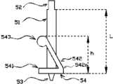
图5为电极销侧视图;Fig. 5 is a side view of an electrode pin;
图6为图5中电极销A-A方向视图;Fig. 6 is a view in the direction of electrode pin A-A in Fig. 5;
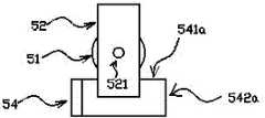
图7为电极销俯视图;Figure 7 is a top view of the electrode pin;
图8经线固定锁立体图。Fig. 8 is a perspective view of the warp fixing lock.
具体实施方式Detailed ways
如图2所示,本发明脑电帽包括用来包裹头部的半球状脑电帽主体1,按国际10-20系统中F3、F4、C3、C4、P3、P4、O1、O2电极位置固定在主体1上的电极座2,位于两侧耳下的经线固定锁3,连接两侧经线固定锁3的下颚固定带4以及与电极座2配合使用的电极销5(图2中未示出)。主体1由弹性面料构成,用来包裹前额,头顶及后脑。其中,国际10-20系统中F3、F4、C3、C4、P3、P4、O1、O2为本领域技术人员在脑电采集时选用的常用电位,这些电位包括了脑部主要功能区,从而满足了脑电采集中的需要。脑电帽主体1内有经线6,经线6的两端固定在脑电帽主体两边的经线固定锁3上,且每条经线6穿过两个在头部左右对应的电极座2。其中经线6为含涤纶纤维或橡胶的弹性绳。As shown in Figure 2, the EEG cap of the present invention includes a hemispherical EEG cap
如图3和图4所示,电极座2为圆柱型,母线长为CL,在轴心处沿轴线方向有一插孔21,插孔21包括一圆孔和一与圆孔相通的长方型孔,插孔21沿母线方向贯穿电极座2。其中,圆孔轴线与电极座2的轴线共线。电极座2在脑电帽内侧部分有经线孔22。经线孔22轴线与电极座2上下表面垂直,不与插孔21交叉,且贯穿电极座2。使用时,经线6通过经线孔22穿过电极座2。As shown in Figures 3 and 4, the
如图5、图6和图7所示,电极销5包括:竖直的圆柱型销身51;固定在销身51正上方的长方体销把52;固定在销身正下方的电极触点53;固定在销身51侧面,且底端与销身51底端相连的弹片组54。其中销身51母线长L,L=1.8CL。销把52和电极触点53的几何中心都在销身51的中轴线上。销身51和销把52在前者中轴线上有一导线孔521,导线孔521贯穿销身51与销把52,导线7通过导线孔521连接至电极触点53。弹片组54包括基板541、弹片542、滚头543及连接板544。基板541为水平的长方形板,其边541a通过连接板544与销身51连接。弹片542也是一长方形板,弹片542的一边542a与基板541中的边541a的临边重合。滚头543为一圆柱型结构,固定在弹片边542a的对边。滚头543的母线与销身51母线垂直,滚头543的侧面与弹片542相切。弹片组54整体高度为h,h=CL。弹片组54材料为弹性材料,如弹性塑料、薄铜片等。电极销5与电极座2配合使用。在装配时,先将电极销5在插入电极座2,此时销身51穿过插孔21的圆形孔部分,弹片组54穿过插孔21的矩形部分进入脑电帽内部。电极销5与电极座2相配合时,电极销5穿过插孔21插进脑电帽,其中电极销销身51穿过插孔21的圆形孔,弹片组54穿过插孔21的方形孔。电极销5插入电极座2后,保持电极座2不动,通过销把52针转动电极销5半圈,这时由于销身51母线长度L<h+CL,弹片542被压弯,电极销5被固定在电极座2上,电极触点53指向头部。As shown in Figure 5, Figure 6 and Figure 7, the
如图8所示,经线固定锁3为圆柱型,在经线固定锁3中轴线处有一穿过经线固定锁3上下表面的矩形孔31。在经线固定锁3侧面有一经过其中轴线与矩形孔相交的圆孔32。圆孔32中轴线与经线固定锁3上表面平行,且穿过经线固定锁3。经线固定锁3还包括一与其矩形孔31大小形状均一致的固定锁孔塞。在经线6穿过经线固定锁3时,即可用固定锁孔塞塞入矩形孔31 ,用摩擦力来固定经线6。As shown in FIG. 8 , the
使用时,先将4条经线6各穿过1对在头部左右对应的电极座2的经线孔22,经线6的两端分别通过圆孔32穿过脑电帽主体1两侧的经线固定锁3。4条经线穿好后先将一个固定锁孔塞塞入一个经线固定锁矩形孔31,固定经线的一端。之后,将8个电极销5按电极名称固定到对应的电极座2。之后将脑电帽带在受试者头上,并将下颚固定带4套在受试者的下颚,以固定脑电帽。由于脑电帽采用弹性材料,在带到受试者头部的同时,各电极座也自动的匹配到标准电极位置所对应的点,从而方便了电极定位。带好脑电帽后拉动经线未被固定的一端,使4条经线均略微受力,此时将固定锁孔塞塞入该段的经线固定锁矩形孔31以固定经线6。这样,经线6受力后会使被其穿过的电极座2受到向头部方向的力,使原本电极触点53已经接触到头部的电极销5的弹片542再次受力,弯曲得更大,使其对应的电极座2更加接近头部,带动脑电帽整体更贴近头皮。若在刚戴上脑电帽尚有未与头部接触的电极触点,拉紧经线6后,所有电极座2都离头部更近了些,使未与头部接触的电极触点接触到头部。这样就避免了局部区域存在多个电极时,将脑电帽支撑起来,使区域中个别电极接触不到头皮的情况。When in use, first pass the four
本发明使用时操作简便,电极定位准确,电极触点与头皮接触牢靠,克服了现有技术中定位不准,导电膏用量难以把握,电极与头皮接触不牢靠等缺点,使得脑电采集工作更加快捷、准确。The invention is easy to operate when used, the electrode is positioned accurately, and the electrode contacts are firmly in contact with the scalp, which overcomes the shortcomings of the prior art, such as inaccurate positioning, difficulty in controlling the amount of conductive paste, and unreliable contact between the electrode and the scalp, making the EEG collection work easier. Fast and accurate.
另外,本发明也可根据需要,增加或减少电极座的数量,并配合相应数量的经线,以满足不同情况下脑电采集的需求。In addition, the present invention can also increase or decrease the number of electrode holders according to needs, and cooperate with a corresponding number of warps to meet the needs of EEG collection in different situations.
Claims (3)
Priority Applications (1)
| Application Number | Priority Date | Filing Date | Title |
|---|---|---|---|
| CN201110311884.9ACN102499674B (en) | 2011-10-15 | 2011-10-15 | An EEG cap with a socket structure and multiple guaranteed contacts in close contact with the scalp |
Applications Claiming Priority (1)
| Application Number | Priority Date | Filing Date | Title |
|---|---|---|---|
| CN201110311884.9ACN102499674B (en) | 2011-10-15 | 2011-10-15 | An EEG cap with a socket structure and multiple guaranteed contacts in close contact with the scalp |
Publications (2)
| Publication Number | Publication Date |
|---|---|
| CN102499674A CN102499674A (en) | 2012-06-20 |
| CN102499674Btrue CN102499674B (en) | 2014-01-29 |
Family
ID=46211856
Family Applications (1)
| Application Number | Title | Priority Date | Filing Date |
|---|---|---|---|
| CN201110311884.9AExpired - Fee RelatedCN102499674B (en) | 2011-10-15 | 2011-10-15 | An EEG cap with a socket structure and multiple guaranteed contacts in close contact with the scalp |
Country Status (1)
| Country | Link |
|---|---|
| CN (1) | CN102499674B (en) |
Families Citing this family (6)
| Publication number | Priority date | Publication date | Assignee | Title |
|---|---|---|---|---|
| CN105030235B (en)* | 2015-07-08 | 2018-03-27 | 褚明礼 | Headband and brain electricity feedback training instrument with electrode wires |
| CN106861036A (en)* | 2017-03-06 | 2017-06-20 | 桂林市威诺敦医疗器械有限公司 | Fast Installation single-use skin electrode sheet devices |
| CN112656425A (en)* | 2019-09-30 | 2021-04-16 | 脑云(常州)医疗科技有限公司 | Electroencephalogram cap based on improved electrode |
| CN112656426A (en)* | 2019-09-30 | 2021-04-16 | 脑云(常州)医疗科技有限公司 | Electroencephalogram cap with multiple contact guaranteeing functions and capable of being in close contact with scalp |
| EP4101382B1 (en)* | 2020-02-07 | 2025-02-19 | NOK Corporation | Bioelectrode |
| GB2620384A (en) | 2022-07-01 | 2024-01-10 | Neuronostics Ltd | Method and system for estimating dynamic seizure likelihood |
Family Cites Families (7)
| Publication number | Priority date | Publication date | Assignee | Title |
|---|---|---|---|---|
| US20040073129A1 (en)* | 2002-10-15 | 2004-04-15 | Ssi Corporation | EEG system for time-scaling presentations |
| CN100546538C (en)* | 2007-06-13 | 2009-10-07 | 中国科学院半导体研究所 | A method of making dry skin electrode |
| WO2009006397A2 (en)* | 2007-06-28 | 2009-01-08 | University Of Pittsburgh-Of The Commonwealth System Of Higher Education | Electrode systems and methods comprising a hydrophilic swollen polymer |
| US10987015B2 (en)* | 2009-08-24 | 2021-04-27 | Nielsen Consumer Llc | Dry electrodes for electroencephalography |
| TWI383779B (en)* | 2009-12-18 | 2013-02-01 | Univ Nat Chiao Tung | Biomedical electric wave sensor |
| EP2474263B1 (en)* | 2010-03-24 | 2013-05-22 | Brain Products GmbH | Attaching device for holding dry electrodes for detecting EEG signals |
| CN202313323U (en)* | 2011-10-15 | 2012-07-11 | 杭州电子科技大学 | Electroencephalogram cap adopting socket structure |
- 2011
- 2011-10-15CNCN201110311884.9Apatent/CN102499674B/ennot_activeExpired - Fee Related
Also Published As
| Publication number | Publication date |
|---|---|
| CN102499674A (en) | 2012-06-20 |
Similar Documents
| Publication | Publication Date | Title |
|---|---|---|
| CN102499674B (en) | An EEG cap with a socket structure and multiple guaranteed contacts in close contact with the scalp | |
| CN110710966B (en) | A sucker-type wearable flexible brain magnetic cap for measuring magnetic field signals in the human brain | |
| CN201323364Y (en) | Electric connector | |
| US20240164684A1 (en) | Elastic electroencephalography dry electrode, electroencephalography device and application system | |
| CN108378847A (en) | A kind of brain electricity cap free of cleaning | |
| US20190343458A1 (en) | Assembled head-mounted module for sensing brain activity and head-mounted device for sensing brain activity | |
| CN203914913U (en) | Dry electrode brain electricity cap | |
| CN104124919A (en) | Rodlike probe and measuring device used for solar cell unit | |
| CN107582052A (en) | A kind of Saline-based electrodes cap | |
| CN102323857A (en) | Brain-computer interface electrode cap based on elastic array | |
| CN107835655A (en) | Minimize the high-performance nerve probe structure of neurotrosis | |
| CN105852855A (en) | Implantable cerebral electrode for measuring cerebral primary visual electrocorticograms in rodents | |
| CN207821815U (en) | A kind of flexibility dry-type electrode | |
| CN110916651A (en) | Skin dry electrode | |
| CN112043266A (en) | A comb-shaped EEG dry electrode wearable device | |
| CN215534443U (en) | Electroencephalogram cap | |
| CN204889982U (en) | Bandeau and brain electricity feedback training appearance with electrode line | |
| CN202313323U (en) | Electroencephalogram cap adopting socket structure | |
| EP3868298A1 (en) | Electrode apparatus and measurement method thereof | |
| CN204318754U (en) | A kind of electrode clip of electrocardiogram | |
| CN102755158A (en) | Comb electrode | |
| CN220141666U (en) | A dry electrode for non-invasive brain-computer interface devices | |
| CN204600469U (en) | Based on the electrode measurement device of genioglossus electromyographic signal | |
| CN202104917U (en) | Device for placing electrical impedance tomography electrodes | |
| CN205586001U (en) | Be used for electrometric implanted brain electrode of muroid brain primary vision cortex brain |
Legal Events
| Date | Code | Title | Description |
|---|---|---|---|
| C06 | Publication | ||
| PB01 | Publication | ||
| C10 | Entry into substantive examination | ||
| SE01 | Entry into force of request for substantive examination | ||
| C14 | Grant of patent or utility model | ||
| GR01 | Patent grant | ||
| TR01 | Transfer of patent right | ||
| TR01 | Transfer of patent right | Effective date of registration:20181123 Address after:313000 industrial zone of Donglin Town, Wuxing District, Huzhou, Zhejiang Patentee after:ZHEJIANG YUANTE NEW MATERIAL CO.,LTD. Address before:310018 2 street, Xiasha Higher Education Park, Hangzhou, Zhejiang Patentee before:HANGZHOU DIANZI University | |
| TR01 | Transfer of patent right | ||
| TR01 | Transfer of patent right | Effective date of registration:20191211 Address after:No.146, Shuangjin Road, Xiannv Town, Jiangdu District, Yangzhou City, Jiangsu Province Patentee after:Yangzhou Zhonggui Motor Technology Co.,Ltd. Address before:313000 Zhejiang Province, Huzhou city Wuxing District East Town Industrial Zone Patentee before:ZHEJIANG YUANTE NEW MATERIAL CO.,LTD. | |
| CF01 | Termination of patent right due to non-payment of annual fee | ||
| CF01 | Termination of patent right due to non-payment of annual fee | Granted publication date:20140129 |