CN102498612A - RF power divider and combiner circuit - Google Patents
RF power divider and combiner circuitDownload PDFInfo
- Publication number
- CN102498612A CN102498612ACN2009801596349ACN200980159634ACN102498612ACN 102498612 ACN102498612 ACN 102498612ACN 2009801596349 ACN2009801596349 ACN 2009801596349ACN 200980159634 ACN200980159634 ACN 200980159634ACN 102498612 ACN102498612 ACN 102498612A
- Authority
- CN
- China
- Prior art keywords
- port
- power divider
- divider circuits
- inductance
- separate
- Prior art date
- Legal status (The legal status is an assumption and is not a legal conclusion. Google has not performed a legal analysis and makes no representation as to the accuracy of the status listed.)
- Pending
Links
Images


Classifications
- H—ELECTRICITY
- H03—ELECTRONIC CIRCUITRY
- H03H—IMPEDANCE NETWORKS, e.g. RESONANT CIRCUITS; RESONATORS
- H03H7/00—Multiple-port networks comprising only passive electrical elements as network components
- H03H7/48—Networks for connecting several sources or loads, working on the same frequency or frequency band, to a common load or source
Landscapes
- Transmitters (AREA)
- Filters And Equalizers (AREA)
Abstract
Description
Translated fromChinese交互参考的相关申请案Cross-Referenced Related Applications
本申请案涉及并主张2009年3月30号所申请的美国暂时申请案第61/164,774号,命名为小型芯片上射频功分器-结合器,在此将其一并纳入参考。This application relates to and claims US Provisional Application No. 61/164,774, filed March 30, 2009, entitled RF Power Divider-Combiner on a Small Chip, which is hereby incorporated by reference.
技术领域technical field
本发明大体上涉及射频(RF)装置,特别涉及一种小型芯片上射频功分器及结合器电路。The present invention relates generally to radio frequency (RF) devices, and more particularly to a small on-chip RF splitter and combiner circuit.
背景技术Background technique
现代无线通信系统运用各种复杂、紧密集成的射频电路,其典型地分成多个链路,每一个分别处理其上的信号。例如,一传统移动电话可运用单一天线来接收一无线(802.11x)以及一蓝芽(802.15.11)信号、运用一独立收发器将该射频信号降频、解调制该基带信号并解碼该基带信号所代表的数字数据。为了使该无线局域网络信号独立于该蓝芽信号进行处理,必须最小化它的影响,也就是,必须将该无线局域网络链路与该蓝芽链路尽可能地隔离。Modern wireless communication systems employ various complex, tightly integrated radio frequency circuits, which are typically divided into multiple links, each processing the signals thereon separately. For example, a conventional mobile phone may use a single antenna to receive a wireless (802.11x) and a Bluetooth (802.15.11) signal, use a separate transceiver to down-convert the RF signal, demodulate the baseband signal, and decode the baseband The digital data represented by a signal. In order for the WLAN signal to be processed independently of the Bluetooth signal, its influence must be minimized, ie the WLAN link must be isolated from the Bluetooth link as much as possible.
现有技术中已提出一些解决方案,其中一者是威尔金森分配器(splitter)或功分器-结合器(power divider-binder)。众所皆知地,威尔金森分配器包含一共同端口和二或更多独立端口,每一个端口具有相同阻抗。在充当一功分器来操作的二路分配器(two-way splitter)中,施加至该共同端口的信号在该二独立端口中的每一端口被分成具有同相位的二相等部分。独立端口的功率水平为该共同端口的功率水平的一半。在充当一功率结合器来操作时,施加至任一独立端口的信号于该共同端口处是以其功率水平的一半来输出,且二个同相位的信号同时被施加至独立端口,将其加总并于该共同端口处以结合功率水平来输出。理想地,独立端口彼此间互相隔离,没有被输入至上述独立端口中其中一者的信号以一预定操作频率输出至任何另一个独立端口。然而,在实际配置中,在上述独立端口间可能会有少量的泄漏。Some solutions have been proposed in the prior art, one of which is a Wilkinson splitter or a power divider-binder. As is well known, a Wilkinson divider consists of a common port and two or more independent ports, each port having the same impedance. In a two-way splitter operating as a power divider, the signal applied to the common port is divided into two equal parts having the same phase at each of the two independent ports. The power level of the individual port is half that of the common port. When operating as a power combiner, the signal applied to any independent port is output at the common port at half its power level, and two signals in phase are simultaneously applied to the independent ports, combining them The sum is output at the common port at the combined power level. Ideally, the independent ports are isolated from each other, and a signal not input to one of the independent ports is output to any other independent port at a predetermined operating frequency. However, in actual configurations, there may be a small amount of leakage between the aforementioned individual ports.
在该威尔金森功分器被配置的一种方式中利用到四分之一波长的传输线,每一条传输线连接该共同端口至各自的独立端口。所选取的传输线的长度为该预定操作频率波长的四分之一。此外,于上述各独立端口之间连接镇流电阻端口,用以消耗额外功率并隔离一独立端口与另一独立端口。若不能实现需要的四分之一波长传输线或具有无法接受的高插损时,可在该共同端口和其余传输线的接点之间增加一额外四分之传输线。利用在该镇流电阻和独立端口之间的额外四分之一波长传输线,不均等功率分配器是可行的,其中,这类传输线依据所要的分配比率而具有不同阻抗。In one manner in which the Wilkinson divider is configured utilizing quarter wavelength transmission lines, each transmission line connects the common port to a respective independent port. The length of the selected transmission line is one quarter of the wavelength of the predetermined operating frequency. In addition, ballast resistor ports are connected between the independent ports to consume extra power and isolate one independent port from another independent port. If the required quarter wavelength transmission line cannot be realized or has an unacceptably high insertion loss, an additional quarter transmission line can be added between the joint of the common port and the rest of the transmission lines. Unequal power splitters are possible with additional quarter-wavelength transmission lines between the ballast resistor and the individual ports, where such transmission lines have different impedances depending on the desired split ratio.
然而,因为它的占用空间大,所以四分之一波长传输线大体上不适合用于制造低成本应用的半导体裸片,特别是针对低于6千兆赫的操作频率更不适合。因此,用以降低该四分之一波长传输线的占用空间的一些方式已被提出。一种方式指示着将该传输线分成二部分,其中每一部分具有高于单一传输线的阻抗,及一电容并联至该镇流电阻。也可运用单一较高阻抗(但是较短)的传输线,每一端口包含一接地的电容。尽管可以降低该四分之一波长传输线的总长度,但是该电路的整体占用空间对于芯片上制造而言仍是无法接受的大,特别是具有上述额外电容器。更进一步,高传输线阻抗使得插损增加。However, because of its large footprint, quarter-wavelength transmission lines are generally unsuitable for fabricating semiconductor die for low-cost applications, especially for operating frequencies below 6 gigahertz. Therefore, several approaches to reduce the footprint of the quarter-wave transmission line have been proposed. One way indicates that the transmission line is divided into two parts, each part has a higher impedance than a single transmission line, and a capacitor is connected in parallel to the ballast resistor. A single higher impedance (but shorter) transmission line can also be used, with each port including a capacitor to ground. Although the overall length of the quarter-wavelength transmission line can be reduced, the overall footprint of the circuit is still unacceptably large for on-chip fabrication, especially with the aforementioned extra capacitors. Furthermore, high transmission line impedance increases insertion loss.
降低威尔金森分配器尺寸的另一方式提出以集中电容和电感来取代上述四分之一波长传输线。更特别地,将集中组件配置成“π”状,其中,一对电容各自接地并接至该电感的相对端。另一变化例包含一“T”状配置,其中,二个电容是串联该共同端口和该独立端口,该电感接地并连结至二个电容之间的接点。然而显然地,降低尺寸对于多数芯片上制造而言是不够的。电感的值大需要实体的隔离,尤其是用于避开贡献至互耦部分的性能的下降。更进一步,需要三个独立通孔以分开每一个电容的接地,其需要额外的裸片有效面积。虽然可运用一共同通孔,但是端口间的隔离会减少。主动式电感可被取代,但是具有波封变化的数字信号的额外电流流出和性能降低会限制它的利用率。Another way to reduce the size of the Wilkinson divider proposes to replace the aforementioned quarter-wavelength transmission lines with lumped capacitance and inductance. More specifically, the centralized assembly is configured in a "π" shape, wherein a pair of capacitors are each grounded and connected to opposite ends of the inductor. Another variation includes a "T" configuration in which two capacitors are connected in series with the common port and the separate port, and the inductor is grounded and connected to the junction between the two capacitors. Clearly, however, size reduction is not enough for most on-chip fabrication. A large value of inductance requires physical isolation, especially to avoid performance degradation contributed to the mutual coupling part. Furthermore, three separate vias are required to separate the ground of each capacitor, which requires additional die real estate. Although a common via could be used, the isolation between ports would be reduced. An active inductor could be substituted, but the extra current draw and performance degradation of digital signals with envelope variations limits its utilization.
现有的功率分配器电路在一些不同的方面是有缺点的。因此,有需要改进习知技术中的芯片上射频功分器及结合器电路。Existing power divider circuits are disadvantageous in a number of different ways. Therefore, there is a need to improve the conventional on-chip RF power splitter and combiner circuits.
发明内容Contents of the invention
依据本发明之一实施例,提出一种具有一预定操作频率的射频(RF)功率分配器电路。该电路可包含一共同端口与一第一和第二分离端口。此外,该电路可包含一第一电感,连接至该第第一分离端口和该共同端口。也可具有一第二电感,其连接至该第二分离端口和该共同端口。该电路还可包含并行连接至该第一分离端口和该第二分离端口的一共振电容,以及连接至该第一分离端口和该第二分离端口的一补偿电阻。于预定操作频率时,该共振电容、该补偿电阻与该第一和第二电感可在该第一分离端口和该第二分离端口之间定义一平行共振电路端口端口。According to an embodiment of the present invention, a radio frequency (RF) power splitter circuit having a predetermined operating frequency is provided. The circuit may include a common port and a first and second split port. Additionally, the circuit may include a first inductor connected to the first split port and the common port. There may also be a second inductor connected to the second split port and the common port. The circuit may also include a resonant capacitor connected in parallel to the first split port and the second split port, and a compensation resistor connected to the first split port and the second split port. The resonant capacitor, the compensating resistor and the first and second inductors may define a parallel resonant circuit port between the first split port and the second split port at a predetermined operating frequency.
参照下列详细说明并结合附图来阅读时,将会对本发明更加了解。The invention will be better understood with reference to the following detailed description when read in conjunction with the accompanying drawings.
附图说明Description of drawings
参照下列说明及附图,在此所揭示的各种实施例的这些和其它特性与优势将会更加了解,其中:These and other features and advantages of the various embodiments disclosed herein will become more apparent with reference to the following description and drawings, in which:
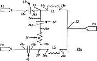
图1为根据本发明的射频(RF)功率分配器电路的基本配置示意图;1 is a schematic diagram of a basic configuration of a radio frequency (RF) power divider circuit according to the present invention;
图2说明图1所示的射频功率分配器电路的基本配置的散射参数(S参数)图;Figure 2 illustrates a graph of scattering parameters (S-parameters) for the basic configuration of the RF power divider circuit shown in Figure 1;
图3为包含用以分开分离端口的耦合补偿电容的射频功率分配器电路的第一实施例示意图;3 is a schematic diagram of a first embodiment of a radio frequency power splitter circuit including coupling compensation capacitors for separating split ports;
图4为具有耦合至共同端口的单一补偿电容的射频功率分配器电路的第二实施例示意图;4 is a schematic diagram of a second embodiment of an RF power divider circuit with a single compensation capacitor coupled to a common port;
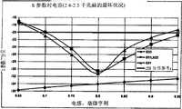
图5显示图3和4各自所示的射频功率分配器电路的第一和第二实施例的S参数图;Figure 5 shows the S-parameter diagrams of the first and second embodiments of the RF power splitter circuits shown in Figures 3 and 4, respectively;
图6为具有耦合电感的射频功率分配器电路的第三实施例示意图;6 is a schematic diagram of a third embodiment of a radio frequency power divider circuit with a coupled inductor;
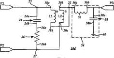
图7为具有耦合电感和一阻抗转换网络的射频功率分配器电路的第四实施例示意图;7 is a schematic diagram of a fourth embodiment of a radio frequency power divider circuit with coupled inductors and an impedance conversion network;
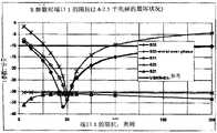
图8显示图6所示的射频功率分配器电路的第三实施例的S参数图;Fig. 8 shows the S parameter diagram of the third embodiment of the radio frequency power divider circuit shown in Fig. 6;
图9A-G为包含电容值、电阻值、电感值、耦合系数、电容损失、分离端口阻抗和共同端口阻抗的组件差异值所产生的S参数变化。9A-G are S-parameter variations produced by component differences including capacitance, resistance, inductance, coupling coefficient, capacitance loss, split port impedance, and common port impedance.
共同参考号被使用于全部附图和详细说明以指示相同组件。Common reference numbers are used throughout the drawings and detailed description to refer to the same components.
具体实施方式Detailed ways
下列结合附图所提出的详细说明想要说明本发明目前较佳实施例,并非代表发展或运用本发明的唯一形式。本说明结合所示实施例提出本发明的功能。然而,要了解到其也可由不同实施例来达成相同或等效功能,这些不同实施例也想要被包括于本发明范围内的。进一步了解到相关用语的使用,例如第一和第二与相类似者的使用,只是用于区分一实体与另一实体,不必然需要或隐含这类实体之间的任何实质的关系或次序。The following detailed description in conjunction with the accompanying drawings is intended to illustrate the presently preferred embodiments of the present invention, and does not represent the only form for developing or using the present invention. This description proposes the functionality of the invention in conjunction with the illustrated embodiments. However, it is to be understood that the same or equivalent functions can be achieved by different embodiments, and these different embodiments are also intended to be included within the scope of the present invention. It is further understood that the use of relative terms, such as the use of first and second and similar, is used only to distinguish one entity from another and does not necessarily require or imply any substantial relationship or order between such entities .
参照图1的示意图,一射频(RF)功率分配器电路10的基本配置包含一第一分离端口P1、一第二分离端口P2和一共同端口P3。根据本实施例,在共同端口P3的阻抗为该第一分离端口P1和该第二分离端口P2的阻抗的一半。通过举例而非限定,该第一分离端口P1和该第二分离端口P2的阻抗设定为50奥姆,如同传统上的标准射频组件,并且该共同端口P3的阻抗设定为25奥姆。然而,要了解到本发明的第一分离端口P1、第二分离端口P2和共同端口P3在未偏离本发明之下,可以任何其它阻抗来取代。Referring to the schematic diagram of FIG. 1 , the basic configuration of a radio frequency (RF)
施加至共同端口P3的信号于该第一分离端口P1和该第二分离端口P2之间均分。在该第一分离端口P1和该第二分离端口P2的信号与在该共同端口P3的信号同相位。在本操作模式中,功率分配器电路10当作一功分器(powerdivider)来操作。在施加二独立射频信号至该第一分离端口P1和该第二分离端口P2,每一个信号的功率为一半,且以一合并信号的方式在共同端口P3输出。该合并信号的相位等于施加至该第一分离端口P1和该第二分离端口P2的各信号的相位。功率分配器电路10当作一功率结合器来操作。此外,要考虑施加至该第一分离端口P1的信号在第二分离端口P2端口的影响最小,反之亦然。The signal applied to the common port P3 is equally divided between the first split port P1 and the second split port P2. The signals at the first split port P1 and the second split port P2 are in phase with the signal at the common port P3. In this mode of operation, the
在功率分配器电路10的各种实施例中,第一分离端口P1连接至一第一电感L1,且第二分离端口P2连接至一第二电感L2。如同在此所运用者,“连接”这个用语是以它最广义的方式来解释,其中一零件是电性连通着另一零件。就这点而言,零件可直接连接至该另一零件,也就是说中间没有零件插置于其间,或者,该零件可间接连接至该另一组件,也就是说具有一或更多中间零件插置于其间。In various embodiments of the
更特别地,该第一电感L1具有连接至该第一分离端口P1的第一端18a,该第二电感L2具有连接至该第二分离端口P2的第一端20a。根据各种实施例,该第一电感L1和该第二电感L2的电感值要最小化以降低插损(insertion loss)。该第一电感L1的第二端18b和该第二电感L2的第二端20b于一共同端口接点22彼此互相连接,并接至该共同端口P3。More particularly, the first inductor L1 has a
一共振电容24并行连接于该第一电感L1和该第二电感L2之间,用于在该第一分离端口P1和该第二分离端口P2之间提供一平行共振。在一预定操作频率下,平行共振隔离该第一分离端口P1与该第二分离端口P2。该共振电容24的电容值是依本目的选取的,以下将有更进一步的说明。该共振电容24包含第一端24a和第二端24b,第一端24a连接至该第一端18a,第二端24b连接至该第二电感L2的第一端20a。因为该平行共振的电感性链路(inductivechain)包含一电阻性损失,所以具有一第一端26a和一第二端26b的补偿电阻26串行连接至该共振电容24。尤其是该共振电容24的第二端24b连接至该补偿电阻26的第一端26a。然而,也可考虑其它实施例,将补偿电阻26并行连接至该共振电容24。该共振电容24的第一端24a连接至该电感L1的第一端18a并于一第一分离端口接点(junction)25处连接至该第一分离端口P1,同时该补偿电阻26的第二端26b连接至该第二电感L2的第一端20a并于一第二分离端口接点(junction)27处连接至该第二分离端口P2。A
根据本发明的一实施例,该第一电感L1和该第二电感L2具有1.34毫微亨利的电感值,该共振电容24具有1.55微微法拉电容值,且该补偿电阻具有17奥姆值。图2依据其仿真显示该功率分配器电路10的散射参数(S参数)。According to an embodiment of the present invention, the first inductor L1 and the second inductor L2 have an inductance of 1.34 nanohenries, the
参照至图2的图形,依据所示的功率分配器电路10的仿真,显示上述散射参数(S参数)。该第一分离端口P1(S11)和该第二分离端口P2(S22)的反射系数是一模一样并显示于图形30。共同端口P3(S33)的反射系数显示于图形32。如那些熟知此项技术的人士所理解地,该反射系数代表各对应端口的回损。施加一信号至该第二分离端口P2,在第二分离端口P2和第一分离端口P1间的隔离是由图形34所显示的传输系数(S21)表示。在所示的特定范例中,该功率分配器电路10具有预定操作频率为2.45千兆赫,且在那个频率下,传输系数(S21)约为-45分贝(dB)。图形36所示端口端口的传输系数(S31和S32)代表着被施加到共同端口P3的信号相对于第一分离端口P1和第二分离端口P2为信号衰减。Referring to the graph of FIG. 2 , according to a simulation of the
第一分离端口P1、第二分离端口P2和共同端口P3的阻抗为具有一电感性的零件,因此,本发明的其它实施例想使用补偿电容。就如同在基本实施例中,共同端口P3的阻抗为第一分离端口P1和第二分离端口P2的阻抗的一分数,尤其是二分之一。The impedances of the first split port P1, the second split port P2 and the common port P3 are inductive components, therefore, other embodiments of the present invention want to use compensation capacitors. As in the basic embodiment, the impedance of the common port P3 is a fraction, in particular half, of the impedances of the first split port P1 and the second split port P2.
参照图3的示意图,射频功率分配器电路10a的第一实施例包含连接至第一电感L1的第一分离端口P1。就如同前述实施例,该第一分离端口P1具有50奥姆的阻抗。然而,在第一分离端口P1和第一分离端口接点25之间插入一第一补偿电容38。该第一补偿电容38具有一第一端38a,第一端38a连接至该第一分离端口P 1,以及一第二端38b,其连接至共振电容24的第一端24a和第一电感L1的第一端18a。第一电感L1的第二端18b连接至共同端口接点22并连接至共同端口P3。Referring to the schematic diagram of FIG. 3, a first embodiment of an RF
一第二补偿电容40插置于第二分离端口P2和第二电感L2之间,第二分离端口P2以类似方式连接至第二电感L2端口。该第二分离端口P2同样具有50奥姆的阻抗。第二补偿电容40具有一第一端40a以及一第二端40b,第一端40a连接至该第一分离端口P1,第二端40b连接至该补偿电阻26的第二端26b和该第二电感L2的第一端20a。第二电感L2的第二端20b也连接至共同端口接点22和共同端口P3,其具有25奥姆的阻抗。A
如上所述,该第一补偿电容38和该第二补偿电容40更佳地匹配该第一分离端口P1和该第二分离端口P2的阻抗。更进一步,分别选取该第一补偿电容38和该第二补偿电容40的值,用以最小化该预定操作频率下的第一分离端口P1和第二分离端口P2的回损。只是举例而非限定,所选取的第一补偿电容38和第二补偿电容40两者分别为4微微法拉(4pF)电容值。As mentioned above, the
所选取的第一电感L1和第二电感L2的电感值相等且为最小值,用以最小化插损。在显示于图3的示范性实施例中,第一电感L1和第二电感L2各具有1.35毫微亨利值(nH)。The selected inductance values of the first inductor L1 and the second inductor L2 are equal and minimum, so as to minimize the insertion loss. In the exemplary embodiment shown in FIG. 3 , each of the first inductor L1 and the second inductor L2 has a value of 1.35 nanoHenries (nH).
大体上,在前述架构中,共振电容24和补偿电阻26并行连接于第一电感L1和第二电感L2之间,以定义一平行共振。根据第一实施例,该共振电容24具有1.55微微法拉的电容值。在该示范性实施例中,预定操作频率为2.45千兆赫,该平行共振隔离该第一分离端口P1与该第二分离端口P2。该补偿电阻26串行连接着该共振电容24,补偿电阻26的第一端26a连接至该共振电容24的第二端24b。选取该补偿电阻26的值以最大化该第一分离端口P1和该第二分离端口P2之间的隔离,在本实施例中,该补偿电阻26具有17奥姆的电阻值。本发明的一实施例为在该预定操作频率下具有一20分贝的隔离。Generally, in the aforementioned architecture, the
参照图5的图形,显示该射频功率分配器电路10a的第一实施例模拟的S参数。如图形44所示,该第一分离端口P1(S11)和该第二分离端口P2(S22)的反射系数还是一模一样。共同端口P3(S33)的反射系数显示于图形46,其指出在2.45千兆赫(GHz)的预定操作频率下,回损降低到约-25分贝。在该预定操作频率下,如图形48所示的传输系数(S21),在该第一分离端口P1和该第二分离端口P2之间的隔离约为-45分贝。传输系数(S31和S32)显示于图形50。如图所示,随着在该第一分离端口P1和该第二分离端口P2分别引入该第一补偿电容38和该第二补偿电容40,可改善阻抗匹配,同时在该第一分离端口P1和该第二分离端口P2之间仍维持高隔离。Referring to the graph of FIG. 5, the simulated S-parameters of the first embodiment of the radio frequency
此外,该图形显示在低频(或接近直流)时,第一分离端口P1和第二分离端口P2之间具有高度隔离。那些熟知此项技术的人士会认知到这类特征适合用于涉及连接至分离端口的二个不同的高敏感度接收器链路的应用中。尤其是,在其它的接收链路中,来自一接收器链路的基带信号和相关低频混波产物的泄漏实质减少了。本示范性应用不是要限定本发明,本射频功率分配器电路10可以各式各样方式运用。Furthermore, the graph shows that at low frequencies (or close to DC), there is a high degree of isolation between the first split port P1 and the second split port P2. Those skilled in the art will recognize that this type of feature is suitable for use in applications involving two different highly sensitive receiver chains connected to separate ports. In particular, leakage of baseband signals and associated low frequency mixing products from a receiver chain is substantially reduced in other receive chains. This exemplary application is not intended to limit the invention, and the RF
现在参照图4的示意图,射频功率分配器电路10b的第二实施例包含连接至第一电感L1的第一分离端口P1和连接至第二电感L2的第二分离端口P2。一共享补偿电容52串行连接于该共同端口P3和该共同端口接点22之间,也就是,互连的第一电感L1和第二电感L2的交点定义为接点,该接点为共享补偿电容52。更详细地,该共享补偿电容52具有连接至该第一电感L1和该第二电感L2的第一端52a,及连接至该共同端口P3的第二端52b。Referring now to the schematic diagram of FIG. 4, a second embodiment of an RF power splitter circuit 10b includes a first split port P1 connected to a first inductor L1 and a second split port P2 connected to a second inductor L2. A shared compensation capacitor 52 is serially connected between the common port P3 and the
共享补偿电容52可以更佳地匹配第一分离端口P1、第二分离端口P2和共同端口P3的阻抗。如同在前述实施例中,第一分离端口P1和第二分离端口P2两者具有50奥姆的阻抗,而该共同端口P3具有25奥姆的阻抗。在预定操作频率下,选取该补偿电容52的值以最小化第一分离端口P1、第二分离端口P2和共同端口P3每个端口的回损。在所示的示范性实施例中,该补偿电容52具有6微微法拉的电容值。The shared compensation capacitor 52 can better match the impedances of the first split port P1 , the second split port P2 and the common port P3 . As in the previous embodiment, both the first split port P1 and the second split port P2 have an impedance of 50 ohms, while the common port P3 has an impedance of 25 ohms. At a predetermined operating frequency, the value of the compensation capacitor 52 is selected to minimize the return loss of each of the first split port P1 , the second split port P2 and the common port P3 . In the exemplary embodiment shown, the compensation capacitor 52 has a capacitance of 6 picofarads.
该共振电容24并行连接于该第一电感L1和该第二电感L2之间,以在该第一分离端口P1和该第二分离端口P2之间提供一平行共振。如同前述实施例,在该预定操作频率下,平行共振隔离第一分离端口P1与第二分离端口P2。共振电容24的第一端24a连接至第一电感L1的第一端18a,共振电容24的第二端24b连接至补偿电阻26的第一端26a。接着,补偿电阻26的第二端26b连接至第二电感L2的第一端20a及第二分离端口P2与第二分离端口接点27。The
举例来说,第一电感L1和第二电感L2具有1.35毫微亨利的电感值,共振电容24具有1.86微微法拉的电容值,且该补偿电阻具有15奥姆值。要了解,第一电感L1和第二电感L2以奥姆计算的电阻性损失等于以毫微亨利计算的电感值,尤其是这类零件可被制造于半导体裸片上。更进一步,第一电感L1和第二电感L2以奥姆计算的电阻性损失可以是以毫微亨利计算的电感值的两倍。因此,尽管相较于上述传统威尔金森功分器插损是降低的,但是第一分离端口P1和第二分离端口P2之间的隔离也是下降的。就这点而言,可调整共振电容24和补偿电容52的电容值还有调整该补偿电阻26的电阻值。For example, the first inductor L1 and the second inductor L2 have an inductance of 1.35 nanohenries, the
要了解,射频功率分配器电路10中的电感占用最多裸片的有效面积,且该电感值越大则它的尺寸越大。因此,降低该电感值的好处为双重的:尺寸下降和插损下降。然而,为了维持相同的性能特征,可增加共振电容24的电容值。因此,在本发明的另一实施例,第一电感L1和第二电感L2具有0.8毫微亨利的电感值(及相对应的1.6奥姆的电阻值),而该共振电容24的电容值为27微微法拉。补偿电阻26也被修改为2.8奥姆的电阻值,且共享补偿电容52可具有8微微法拉的电容值。It is to be understood that the inductor in the RF
在上述实施例中,第一电感L1和第二电感L2彼此间是实体上的分开,使其具有所述的性能特征。然而,图6显示替代的射频功率分配器电路10c的第三实施例,利用耦合电感,使其不需实体隔离,有助于降低整体的占用空间。In the above embodiments, the first inductor L1 and the second inductor L2 are physically separated from each other, so that they have the above-mentioned performance characteristics. However, FIG. 6 shows a third embodiment of an alternative RF
射频功率分配器电路10c的第三实施例包含连接至第一耦合电感L1的第一分离端口P1,以及连接至第二电感L2的第二分离端口P2。第一耦合电感L1的第一端18a连接至第一分离端口P1,且第二耦合电感L2具有连接至第二分离端口P2的第一端20a。第一分离端口P1和第二分离端口P2的阻抗为50奥姆。该第一电感L1的第二端18b和该第二耦合电感L2的第二端20b于该共同端口接点22彼此相连并连接至共同端口P3,其具有25奥姆的阻抗。A third embodiment of the RF
选取该第一耦合电感L1和该第二耦合电感L2的电感值以最小化插损。更进一步,第一耦合电感L1和第二耦合电感L2具有高耦合系数。当第一耦合电感L1和第二耦合电感L2被用在制造于半导体裸片的单一层上,耦合系数(k)约为0.7。或者,当第一耦合电感L1和第二耦合电感L2被用在制造于半导体裸片的不同层数上,例如双层装置(dual layer device),,耦合系数(k)约为0.9。如上所述,以奥姆计算的第一耦合电感L1和第二耦合电感L2的电阻性损失约为以毫微亨利计算的电感值的二倍。在一示范性实施例中,第一耦合电感L1和第二耦合电感L2具有0.8毫微亨利的电感值和1.6奥姆的电阻性损失。The inductance values of the first coupled inductor L1 and the second coupled inductor L2 are selected to minimize insertion loss. Furthermore, the first coupled inductor L1 and the second coupled inductor L2 have a high coupling coefficient. When the first coupled inductor L1 and the second coupled inductor L2 are used on a single layer fabricated on a semiconductor die, the coupling coefficient (k) is about 0.7. Alternatively, when the first coupled inductor L1 and the second coupled inductor L2 are used on different layers fabricated on the semiconductor die, such as a dual layer device, the coupling coefficient (k) is about 0.9. As mentioned above, the resistive losses of the first coupled inductor L1 and the second coupled inductor L2 calculated in ohms are about twice the inductance values calculated in nanohenries. In an exemplary embodiment, the first coupled inductor L1 and the second coupled inductor L2 have an inductance of 0.8 nanohenries and a resistive loss of 1.6 ohms.
共振电容24并行连接于第一耦合电感L1和第二耦合电感L2之间,用于在第一分离端口P1和第二分离端口P2之间提供一平行共振。在预定操作频率下,该平行共振隔离第一分离端口P1与第二分离端口P2。更详细地,共振电容24的第一端24a连接至第一电感L1的第一端18a,且补偿电阻26的第一端26a连接至该共振电容24的第二端24b。补偿电阻26的第二端26b连接至第二耦合电感L2的第一端20a及第二分离端口P2与第二分离端口接点27。根据一示范性实施例,共振电容24具有1.6微微法拉的电容值,且补偿电阻26具有16奥姆的电阻值。The
如前所述,第一分离端口P1和第二分离端口P2的阻抗为共同端口P3的阻抗的二倍。参照至图7的示意图,在预定操作频率下,第四实施例的射频功率分配器电路10d的共同端口P3与该第一分离端口P1和该第二分离端口P2具有相同阻抗。例如,端口每个端口具有50奥姆的阻抗。尤其,射频功率分配器电路10d具有一阻抗转换网络(impedance transformation network)54,串行连接于第一耦合电感L1和第二耦合电感L2的共同端口接点22与共同端口P3之间。然而,共同端口接点22具有的阻抗值为第一分离端口P1和第二分离端口P2的阻抗值的一半。就这点而言,阻抗转换网络54将共同端口接点22的较低阻抗,其为25奥姆,转换为上示共同端口P3的50奥姆的较高阻抗。As mentioned above, the impedance of the first split port P1 and the second split port P2 is twice the impedance of the common port P3. Referring to the schematic diagram of FIG. 7 , at a predetermined operating frequency, the common port P3 of the RF
更详细地,阻抗转换网络54包含一转换电感56和一转换电容58。转换电感56具有连接至共同端口接点22的第一端56a及连接至转换电容58和共同端口P3的第二端56b。转换电容58具有连接至转换电感56的第一端58a及连至接地60的第二端58b。在所示的示范性实施例中,转换电感56具有1.55毫微亨利的电感值。转换电容58具有1.25微微法拉的电容值。In more detail, the
现在参照图8的图形,其显示第三实施例,射频功率分配器电路10c的模拟S参数。图形44所示的第一分离端口P1(S11)和第二分离端口P2(S22)的反射系数是一模一样。共同端口P3(S33)的反射系数显示于图形60。这个指示着在2.54千兆赫的预定操作频率下,回损约为-35分贝。在第一分离端口P1和第二分离端口P2之间的隔离显示于图形64中代表(S21),在2.54千兆赫的预定操作频率下,其大于-50分贝。传输系数(S31和S32)显示于图形66,其在图标频率范围内维持常数。除了共同端口P3(S33)的反射系数较接近第一分离端口P1(S11)和第二分离端口P2(S22)的反射系数外,第四实施例的射频功率分配器电路10d的S参数实质上类似于第三实施例10c的S参数。就此点而言,该第四实施例10d的性能类似于含四分之一波长传输线组件的理想威尔金森功分器-结合器的性能。Referring now to the graph of FIG. 8, which shows simulated S-parameters of a third embodiment, radio frequency
根据本发明,在此提出不同预定操作频率的多个电路。如同一基本设计程序,固定并选取包含第一电感L1和第二电感L2的电感值。之后,选取共振电容24的值以在预定操作频率下得到一共振电路。调整补偿电阻26以在预定操作频率下使得第一分离端口P1和第二分离端口P2之间的隔离最大。依据本揭示,那些熟知此项技术的人士能够决定最佳电路参数,尤其是通过一或更多次重复地分别调整共振电容24的电容值和补偿电阻26的电阻值来决定最佳电路参数。可了解的是,这类最佳电路参数在所有端口P1、P2和P3之间几乎达到完美的匹配。According to the invention, a plurality of circuits of different predetermined operating frequencies are proposed here. Like a basic design procedure, the inductance values including the first inductor L1 and the second inductor L2 are fixed and selected. Afterwards, the value of the
要理解到,射频功率分配器电路10的零件可依据具标称值(nominal values)而有不同的公差,使其可以有不同的效能特征。如上所述,本发明的一些实施例是关于在单一半导体裸片上制造射频功率分配器电路10与其它电路,例如功率放大器、低噪音放大器及类似者。该裸片可由一硅基板、一砷化镓基板或任何其合适半导体材料所制造。如同下面更详细的说明,这类半导体制程具有相关的公差,其随不同零件而改变。图9A-G的图显示这类变化在S参数所引起的效应。It is to be understood that the components of the RF
参照至图9A的图显示,预定操作频率在2.4至2.45千兆赫时,传输系数(S21)和反射系数(S11、S22及S33)的变化对电容值的变化。几何尺寸固定的传统半导体制程对于不同批晶圆的电容值典型地具有+/-15%的变化,因此,在1.6微微法拉的标称值,最坏状况的S参数为-20分贝。The graph referring to FIG. 9A shows the variation of transmission coefficient ( S21 ) and reflection coefficient ( S11 , S22 and S33 ) versus capacitance value for a predetermined operating frequency of 2.4 to 2.45 GHz. Conventional semiconductor processes with fixed geometry typically have +/-15% variation in capacitance from wafer to lot, so at a nominal value of 1.6 picofarads, the worst case S-parameter is -20 dB.
图9B的图显示,在2.4至2.45千兆赫的预定操作频率时,传输系数(S21)和反射系数(S11、S22及S33)的变化对电阻值上的变化。要了解,具有固定几何尺寸的传统半导体制程在不同批晶圆的电阻值上典型地具有+/-40%的变化,因此,在16奥姆的标称值,最坏状况的S参数为-20分贝。Figure 9B is a graph showing changes in transmission coefficient (S21) and reflection coefficients (S11, S22, and S33) versus change in resistance value for a predetermined operating frequency of 2.4 to 2.45 GHz. Be aware that traditional semiconductor processes with fixed geometries typically have +/- 40% variation in resistance value from lot to lot of wafers, so at a nominal value of 16 ohms, the worst case S-parameters are - 20 decibels.
图9C的图显示,在2.4至2.45千兆赫的预定操作频率时,传输系数(S21)和反射系数(S11、S22及S33)的变化对电感值上的变化。具有固定几何尺寸的传统半导体制程在不同批晶圆的电感值上典型地具有+/-5%的变化,因此,’在0.8毫微亨利标称值,最坏状况的S参数为-25分贝。Figure 9C is a graph showing changes in transmission coefficient (S21) and reflection coefficients (S11, S22, and S33) versus change in inductance value for a predetermined operating frequency of 2.4 to 2.45 GHz. Traditional semiconductor processes with fixed geometries typically have +/-5% variation in inductance value from lot to lot, so, 'at 0.8 nanohenry nominal, the worst case S-parameter is -25dB .
图9D的图显示,在2.4至2.45千兆赫的预定操作频率时,传输系数(S21)和反射系数(S11、S22及S33)的变化对耦合系数值(coupling coefficient values)上的变化。要了解,具有固定几何尺寸的传统半导体制程在不同批晶圆的耦合系数上典型地具有+/-5%的变化,因此,在0.9标称k值,最坏状况的S参数为-25分贝。Figure 9D is a graph showing variation in transmission coefficient (S21) and reflection coefficient (S11, S22, and S33) versus variation in coupling coefficient values at predetermined operating frequencies of 2.4 to 2.45 GHz. Be aware that traditional semiconductor processes with fixed geometries typically have +/-5% variation in coupling coefficient from lot to lot, so at a nominal k value of 0.9, the worst case S-parameter is -25dB .
图9E的图显示,在2.4至2.45千兆赫的预定操作频率时,传输系数(S21)和反射系数(S11、S22及S33)的变化对电感值损失的变化。在2奥姆至4.8奥姆之间变动时,最坏状况的电感损失影响S参数至少低于-20分贝。Figure 9E is a graph showing the variation of the transmission coefficient (S21) and the reflection coefficient (S11, S22, and S33) versus the loss of inductance value at a predetermined operating frequency of 2.4 to 2.45 GHz. The worst-case inductance loss affects the S-parameters at least below -20 dB when varying between 2 ohms and 4.8 ohms.
图9F及图9G的图分别显示,传输系数(S21)和反射系数(S11、S22及S33)的变化对第一分离端口P1和共同端口P2的阻抗的变化。即使经过大变化,在50奥姆的标称值时,第一分离端口P1和该共同端口P2之间的隔离仍是高的。此外,共同端口P3的匹配条件比分离端口P1或P2更佳。9F and 9G are graphs showing the variation of the transmission coefficient ( S21 ) and the reflection coefficient ( S11 , S22 and S33 ) versus the impedance variation of the first split port P1 and the common port P2 , respectively. Even after large variations, the isolation between the first split port P1 and the common port P2 is still high at a nominal value of 50 ohms. In addition, the matching condition of the common port P3 is better than that of the separate ports P1 or P2.
在此所示特点只是举例提供图示说明本发明实施例的目的,并为了提供据信是最有用且容易了解本发明原理及概念的说明而展现。就此点而言,并未显示比本发明基本了解更详细的本发明细节,配合附图所进行的说明使那些熟知此项技术的人士明白如何具体实现本发明的一些形式。The features shown herein are presented by way of example only for the purpose of illustrating embodiments of the invention, and are presented in order to provide what is believed to be the most useful and easy to understand the principles and concepts of the invention. In this regard, no details of the invention are shown that go beyond a basic understanding of the invention, the description taken with the accompanying drawings to enable those skilled in the art to understand how the invention may be practiced in its forms.
Claims (27)
Applications Claiming Priority (5)
| Application Number | Priority Date | Filing Date | Title |
|---|---|---|---|
| US16477409P | 2009-03-30 | 2009-03-30 | |
| US61/164,774 | 2009-03-30 | ||
| US12/467,049US20100244981A1 (en) | 2009-03-30 | 2009-05-15 | Radio frequency power divider and combiner circuit |
| US12/467,049 | 2009-05-15 | ||
| PCT/US2009/044524WO2010114570A1 (en) | 2009-03-30 | 2009-05-19 | Radio frequency power divider and combiner circuit |
Publications (1)
| Publication Number | Publication Date |
|---|---|
| CN102498612Atrue CN102498612A (en) | 2012-06-13 |
Family
ID=42783414
Family Applications (1)
| Application Number | Title | Priority Date | Filing Date |
|---|---|---|---|
| CN2009801596349APendingCN102498612A (en) | 2009-03-30 | 2009-05-19 | RF power divider and combiner circuit |
Country Status (3)
| Country | Link |
|---|---|
| US (1) | US20100244981A1 (en) |
| CN (1) | CN102498612A (en) |
| WO (1) | WO2010114570A1 (en) |
Cited By (4)
| Publication number | Priority date | Publication date | Assignee | Title |
|---|---|---|---|---|
| CN111867174A (en)* | 2019-04-29 | 2020-10-30 | 青岛海尔智能技术研发有限公司 | A power control method of a radio frequency heating module and a radio frequency heating device |
| TWI796657B (en)* | 2021-03-24 | 2023-03-21 | 國立暨南國際大學 | Power splitter/combiner |
| CN117525799A (en)* | 2024-01-04 | 2024-02-06 | 南京迈矽科微电子科技有限公司 | Compact power divider with high isolation |
| CN117595833A (en)* | 2024-01-16 | 2024-02-23 | 南京迈矽科微电子科技有限公司 | Power distributor and electronic equipment |
Families Citing this family (17)
| Publication number | Priority date | Publication date | Assignee | Title |
|---|---|---|---|---|
| US8258866B2 (en)* | 2010-11-03 | 2012-09-04 | Lockheed Martin Corporation | Power amplifiers |
| US8928429B2 (en) | 2011-05-17 | 2015-01-06 | City University Of Hong Kong | Multiple-way ring cavity power combiner and divider |
| US9137866B2 (en) | 2011-12-12 | 2015-09-15 | Cree, Inc. | Emergency lighting conversion for LED strings |
| US9871404B2 (en) | 2011-12-12 | 2018-01-16 | Cree, Inc. | Emergency lighting devices with LED strings |
| US10117295B2 (en) | 2013-01-24 | 2018-10-30 | Cree, Inc. | LED lighting apparatus for use with AC-output lighting ballasts |
| US10045406B2 (en) | 2013-01-24 | 2018-08-07 | Cree, Inc. | Solid-state lighting apparatus for use with fluorescent ballasts |
| US10104723B2 (en)* | 2013-01-24 | 2018-10-16 | Cree, Inc. | Solid-state lighting apparatus with filament imitation for use with florescent ballasts |
| US9439249B2 (en) | 2013-01-24 | 2016-09-06 | Cree, Inc. | LED lighting apparatus for use with AC-output lighting ballasts |
| US9013246B2 (en)* | 2013-08-01 | 2015-04-21 | Freescale Semiconductor, Inc. | Coupler with distributed feeding and compensation |
| KR102589737B1 (en)* | 2015-12-07 | 2023-10-17 | 삼성전자주식회사 | Power combinder/divider using mutual inductance |
| US10530312B2 (en)* | 2017-12-29 | 2020-01-07 | Bae Systems Information And Electronic Systems Integration Inc. | RF power amplifier |
| US11043931B2 (en) | 2019-11-04 | 2021-06-22 | Analog Devices International Unlimited Company | Power combiner/divider |
| US11609128B2 (en)* | 2019-12-10 | 2023-03-21 | Wiliot, LTD. | Single layer LC oscillator |
| EP3934095A1 (en) | 2020-07-03 | 2022-01-05 | Nxp B.V. | Wilkinson power combiner, communication unit and method therefor |
| US11437992B2 (en) | 2020-07-30 | 2022-09-06 | Mobix Labs, Inc. | Low-loss mm-wave CMOS resonant switch |
| US20220109220A1 (en)* | 2020-10-01 | 2022-04-07 | Mobix Labs, Inc. | Power splitter-combiner circuits in 5g mm-wave beamformer architectures |
| US11695193B2 (en) | 2020-12-14 | 2023-07-04 | Nxp B.V. | Wilkinson power combiner, communication unit and method therefor |
Citations (3)
| Publication number | Priority date | Publication date | Assignee | Title |
|---|---|---|---|---|
| US5977843A (en)* | 1997-04-08 | 1999-11-02 | Kabushiki Kaisha Toshiba | High frequency power divider and high frequency power combiner |
| CN1476650A (en)* | 2000-11-28 | 2004-02-18 | 艾利森电话股份有限公司 | Radio frequency amplifying circuit |
| US20050110594A1 (en)* | 2003-11-21 | 2005-05-26 | Culliton Brian E. | Non-switching adaptable 4-way power splitter/combiner |
Family Cites Families (40)
| Publication number | Priority date | Publication date | Assignee | Title |
|---|---|---|---|---|
| US5126704A (en)* | 1991-04-11 | 1992-06-30 | Harris Corporation | Polyphase divider/combiner |
| US5349313A (en)* | 1992-01-23 | 1994-09-20 | Applied Materials Inc. | Variable RF power splitter |
| DE69630512T2 (en)* | 1995-09-29 | 2004-05-06 | Matsushita Electric Industrial Co., Ltd., Kadoma | POWER AMPLIFIER AND COMMUNICATION DEVICE |
| EP0818829A1 (en)* | 1996-07-12 | 1998-01-14 | Hitachi, Ltd. | Bipolar transistor and method of fabricating it |
| GB2331879B (en)* | 1996-08-05 | 2001-03-28 | Mitsubishi Electric Corp | Radio-frequency integrated circuit for a radio-frequency wireless transmitter-receiver with reduced influence by radio-frequency power leakage |
| KR19980065967A (en)* | 1997-01-17 | 1998-10-15 | 김광호 | Signal Transceiver of Multi-Channel Time Division Communication Method for System Performance Improvement |
| JP3922773B2 (en)* | 1997-11-27 | 2007-05-30 | 三菱電機株式会社 | Power amplifier |
| US6154664A (en)* | 1998-06-24 | 2000-11-28 | Conexant System, Inc. | Dual band cellular phone with two power amplifiers and power control circuit therefore |
| US6735418B1 (en)* | 1999-05-24 | 2004-05-11 | Intel Corporation | Antenna interface |
| US6917789B1 (en)* | 1999-10-21 | 2005-07-12 | Broadcom Corporation | Adaptive radio transceiver with an antenna matching circuit |
| US6498535B1 (en)* | 2000-06-28 | 2002-12-24 | Trw Inc. | High dynamic range low noise amplifier |
| JP2002111415A (en)* | 2000-09-29 | 2002-04-12 | Hitachi Ltd | High frequency power amplifier and wireless communication device |
| US6586993B2 (en)* | 2000-11-08 | 2003-07-01 | Research In Motion Limited | Impedance matching low noise amplifier having a bypass switch |
| US6469587B2 (en)* | 2000-12-04 | 2002-10-22 | Agere Systems Guardian Corp. | Differential LC voltage-controlled oscillator |
| US6690238B2 (en)* | 2000-12-27 | 2004-02-10 | Emhiser Research, Inc. | Variable phase-shifting rf power amplifiers |
| US7120427B1 (en)* | 2001-03-19 | 2006-10-10 | Cisco Systems Wireless Networking (Australia) Pty Limited | CMOS wireless transceiver with programmable characteristics |
| US6741143B2 (en)* | 2001-06-01 | 2004-05-25 | Rf Technologies Corporation | Apparatus and method for in-process high power variable power division |
| US6556075B1 (en)* | 2001-08-24 | 2003-04-29 | Analog Devices, Inc. | Amplifier system and method that approximate constant impedance and quiescent outputs during forward and reverse modes |
| US6529080B1 (en)* | 2001-09-11 | 2003-03-04 | Sirenza Microdevices, Inc. | TOI and power compression bias network |
| US6953980B2 (en)* | 2002-06-11 | 2005-10-11 | Semiconductor Components Industries, Llc | Semiconductor filter circuit and method |
| US6771475B2 (en)* | 2002-06-17 | 2004-08-03 | Broadcom Corporation | Electrostatic protection circuit with impedance matching for radio frequency integrated circuits |
| DE60322583D1 (en)* | 2002-12-11 | 2008-09-11 | R F Magic Inc | INTEGRATED CROSS-LINKING WITH BAND IMPLEMENTATION |
| US7373171B2 (en)* | 2003-02-14 | 2008-05-13 | Tdk Corporation | Front end module |
| JP2005033350A (en)* | 2003-07-09 | 2005-02-03 | Renesas Technology Corp | High frequency power amplification module and semiconductor integrated circuit device |
| US6998709B2 (en)* | 2003-11-05 | 2006-02-14 | Broadcom Corp. | RFIC die-package configuration |
| WO2005083944A1 (en)* | 2004-02-26 | 2005-09-09 | Quorum Systems, Inc. | Using collision avoidance to menimize wireless lan interference in a multi-mode wireless communication device |
| EP3570374B1 (en)* | 2004-06-23 | 2022-04-20 | pSemi Corporation | Integrated rf front end |
| KR100656196B1 (en)* | 2004-08-12 | 2006-12-12 | 삼성전자주식회사 | Time Division Duplex Transmission / Reception Unit Utilizing Transmit and Receive Mode Simultaneously and Self-Diagnostic Method |
| US8000737B2 (en)* | 2004-10-15 | 2011-08-16 | Sky Cross, Inc. | Methods and apparatuses for adaptively controlling antenna parameters to enhance efficiency and maintain antenna size compactness |
| US7348842B2 (en)* | 2005-01-19 | 2008-03-25 | Micro-Mobio | Multi-substrate RF module for wireless communication devices |
| US7315730B2 (en)* | 2005-06-14 | 2008-01-01 | Motorola, Inc. | Architecture for a receiver front end having dual output low noise amplifier driving separate pre-selectors coupled to a transformer for single ended output |
| US20070015472A1 (en)* | 2005-07-15 | 2007-01-18 | Simo Murtojarvi | Multimode transmitter, module, communication device and chip set |
| US20070161358A1 (en)* | 2006-01-12 | 2007-07-12 | Sony Ericsson Mobile Communications Ab | Multiband radio module |
| US7671693B2 (en)* | 2006-02-17 | 2010-03-02 | Samsung Electronics Co., Ltd. | System and method for a tunable impedance matching network |
| US20070232241A1 (en)* | 2006-02-28 | 2007-10-04 | Renaissance Wireless | RF transceiver switching system |
| KR20080034251A (en)* | 2006-10-16 | 2008-04-21 | 삼성전자주식회사 | Apparatus and method for protecting receiving circuit in time division duplex wireless communication system |
| TWI323580B (en)* | 2006-12-29 | 2010-04-11 | Ind Tech Res Inst | Apparatus and method for adaptive wireless channel estimation |
| US8019293B2 (en)* | 2007-03-09 | 2011-09-13 | Skyworks Solutions, Inc. | Controller and method for using a DC-DC converter in a mobile handset |
| US20080279262A1 (en)* | 2007-05-07 | 2008-11-13 | Broadcom Corporation | On chip transmit/receive selection |
| US7702296B2 (en)* | 2007-08-01 | 2010-04-20 | Mediatek Usa Inc. | Transmit/receive switch |
- 2009
- 2009-05-15USUS12/467,049patent/US20100244981A1/ennot_activeAbandoned
- 2009-05-19CNCN2009801596349Apatent/CN102498612A/enactivePending
- 2009-05-19WOPCT/US2009/044524patent/WO2010114570A1/enactiveApplication Filing
Patent Citations (3)
| Publication number | Priority date | Publication date | Assignee | Title |
|---|---|---|---|---|
| US5977843A (en)* | 1997-04-08 | 1999-11-02 | Kabushiki Kaisha Toshiba | High frequency power divider and high frequency power combiner |
| CN1476650A (en)* | 2000-11-28 | 2004-02-18 | 艾利森电话股份有限公司 | Radio frequency amplifying circuit |
| US20050110594A1 (en)* | 2003-11-21 | 2005-05-26 | Culliton Brian E. | Non-switching adaptable 4-way power splitter/combiner |
Cited By (7)
| Publication number | Priority date | Publication date | Assignee | Title |
|---|---|---|---|---|
| CN111867174A (en)* | 2019-04-29 | 2020-10-30 | 青岛海尔智能技术研发有限公司 | A power control method of a radio frequency heating module and a radio frequency heating device |
| CN111867174B (en)* | 2019-04-29 | 2022-12-20 | 青岛海尔智能技术研发有限公司 | A power control method of a radio frequency heating module and a radio frequency heating device |
| TWI796657B (en)* | 2021-03-24 | 2023-03-21 | 國立暨南國際大學 | Power splitter/combiner |
| CN117525799A (en)* | 2024-01-04 | 2024-02-06 | 南京迈矽科微电子科技有限公司 | Compact power divider with high isolation |
| CN117525799B (en)* | 2024-01-04 | 2024-06-21 | 南京迈矽科微电子科技有限公司 | A compact power divider with high isolation |
| CN117595833A (en)* | 2024-01-16 | 2024-02-23 | 南京迈矽科微电子科技有限公司 | Power distributor and electronic equipment |
| CN117595833B (en)* | 2024-01-16 | 2024-04-26 | 南京迈矽科微电子科技有限公司 | Power distributor and electronic equipment |
Also Published As
| Publication number | Publication date |
|---|---|
| US20100244981A1 (en) | 2010-09-30 |
| WO2010114570A1 (en) | 2010-10-07 |
Similar Documents
| Publication | Publication Date | Title |
|---|---|---|
| CN102498612A (en) | RF power divider and combiner circuit | |
| JP6498295B2 (en) | Radio frequency coupler and bidirectional radio frequency coupler | |
| US10200008B2 (en) | High isolation power combiner/splitter and coupler | |
| US9866244B2 (en) | Electromagnetic couplers for multi-frequency power detection | |
| US9008603B2 (en) | Integrated circuit comprising an integrated transformer of the “BALUN” type with several input and output channels | |
| US11750167B2 (en) | Apparatus for radio-frequency matching networks and associated methods | |
| US20230030569A1 (en) | Signal power splitter/combiner with resistance and impedance transformer loading | |
| US10447242B2 (en) | Signal switching systems and modules and devices using same | |
| CN113889735A (en) | Wilkinson power combiner, communication unit and method thereof | |
| CN101953082A (en) | high frequency switch | |
| Lin et al. | A novel miniature dual-band impedance matching network for frequency-dependent complex impedances | |
| Kim et al. | A 115.7–139.7 GHz amplifier with 19.7 dB peak gain and 7.9 dB NF in 40-nm CMOS | |
| Long | On-chip transformer design and application to RF and mm-wave front-ends | |
| WO2016094376A2 (en) | Adjustable rf coupler | |
| CN111181505B (en) | W-band power amplifier | |
| JP4708317B2 (en) | Power distribution and synthesis circuit | |
| KR20200067455A (en) | Compact low loss millimeter-wave power divider and combiner device | |
| Brinkhoff et al. | Integrated filters for 60 GHz systems on CMOS | |
| CN112751151A (en) | High-performance miniaturized directional coupler chip | |
| CN108281743B (en) | On-chip integrated compact broadband power divider | |
| Zhao et al. | Transformer-Based Multisection Quadrature Coupler with 1.5 Octave Bandwidth Using GaAs-Based Integrated Passive Device Technology | |
| Long | and Application to RF | |
| Piekarz et al. | Marchand balun with connecting segment designed with the use of multi-technique compensation | |
| KR101390982B1 (en) | Transmission line structure for dividing power | |
| CN113889736A (en) | Wilkinson power combiner, communication unit and method thereof |
Legal Events
| Date | Code | Title | Description |
|---|---|---|---|
| C06 | Publication | ||
| PB01 | Publication | ||
| C10 | Entry into substantive examination | ||
| SE01 | Entry into force of request for substantive examination | ||
| C02 | Deemed withdrawal of patent application after publication (patent law 2001) | ||
| WD01 | Invention patent application deemed withdrawn after publication | Application publication date:20120613 |