CN102493960A - A fan assembly - Google Patents
A fan assemblyDownload PDFInfo
- Publication number
- CN102493960A CN102493960ACN2011104092598ACN201110409259ACN102493960ACN 102493960 ACN102493960 ACN 102493960ACN 2011104092598 ACN2011104092598 ACN 2011104092598ACN 201110409259 ACN201110409259 ACN 201110409259ACN 102493960 ACN102493960 ACN 102493960A
- Authority
- CN
- China
- Prior art keywords
- base
- fan assembly
- mount
- interlocking
- locking members
- Prior art date
- Legal status (The legal status is an assumption and is not a legal conclusion. Google has not performed a legal analysis and makes no representation as to the accuracy of the status listed.)
- Granted
Links
- 238000005096rolling processMethods0.000description14
- 230000002093peripheral effectEffects0.000description11
- 230000007246mechanismEffects0.000description8
- 230000000694effectsEffects0.000description6
- 238000001816coolingMethods0.000description4
- 125000006850spacer groupChemical group0.000description4
- 239000012530fluidSubstances0.000description3
- 239000006260foamSubstances0.000description3
- 230000004044responseEffects0.000description3
- OKTJSMMVPCPJKN-UHFFFAOYSA-NCarbonChemical compound[C]OKTJSMMVPCPJKN-UHFFFAOYSA-N0.000description2
- 229910052799carbonInorganic materials0.000description2
- 238000010276constructionMethods0.000description2
- 230000007423decreaseEffects0.000description2
- 230000006698inductionEffects0.000description2
- 238000000034methodMethods0.000description2
- 230000010355oscillationEffects0.000description2
- 230000000717retained effectEffects0.000description2
- 238000010079rubber tappingMethods0.000description2
- 241000954177Bangana arizaSpecies0.000description1
- 206010020751HypersensitivityDiseases0.000description1
- 230000009471actionEffects0.000description1
- 230000004913activationEffects0.000description1
- 230000007815allergyEffects0.000description1
- 230000000712assemblyEffects0.000description1
- 238000000429assemblyMethods0.000description1
- 230000008901benefitEffects0.000description1
- 230000015572biosynthetic processEffects0.000description1
- 238000004140cleaningMethods0.000description1
- 238000006073displacement reactionMethods0.000description1
- 238000001704evaporationMethods0.000description1
- 230000008020evaporationEffects0.000description1
- 238000005755formation reactionMethods0.000description1
- 230000005484gravityEffects0.000description1
- 230000006872improvementEffects0.000description1
- 238000005304joiningMethods0.000description1
- 238000003825pressingMethods0.000description1
- 238000006748scratchingMethods0.000description1
- 230000002393scratching effectEffects0.000description1
- 238000009827uniform distributionMethods0.000description1
Images


Classifications
- F—MECHANICAL ENGINEERING; LIGHTING; HEATING; WEAPONS; BLASTING
- F04—POSITIVE - DISPLACEMENT MACHINES FOR LIQUIDS; PUMPS FOR LIQUIDS OR ELASTIC FLUIDS
- F04D—NON-POSITIVE-DISPLACEMENT PUMPS
- F04D25/00—Pumping installations or systems
- F—MECHANICAL ENGINEERING; LIGHTING; HEATING; WEAPONS; BLASTING
- F24—HEATING; RANGES; VENTILATING
- F24F—AIR-CONDITIONING; AIR-HUMIDIFICATION; VENTILATION; USE OF AIR CURRENTS FOR SCREENING
- F24F13/00—Details common to, or for air-conditioning, air-humidification, ventilation or use of air currents for screening
- F24F13/32—Supports for air-conditioning, air-humidification or ventilation units
- F—MECHANICAL ENGINEERING; LIGHTING; HEATING; WEAPONS; BLASTING
- F04—POSITIVE - DISPLACEMENT MACHINES FOR LIQUIDS; PUMPS FOR LIQUIDS OR ELASTIC FLUIDS
- F04D—NON-POSITIVE-DISPLACEMENT PUMPS
- F04D25/00—Pumping installations or systems
- F04D25/02—Units comprising pumps and their driving means
- F04D25/08—Units comprising pumps and their driving means the working fluid being air, e.g. for ventilation
- F—MECHANICAL ENGINEERING; LIGHTING; HEATING; WEAPONS; BLASTING
- F04—POSITIVE - DISPLACEMENT MACHINES FOR LIQUIDS; PUMPS FOR LIQUIDS OR ELASTIC FLUIDS
- F04D—NON-POSITIVE-DISPLACEMENT PUMPS
- F04D29/00—Details, component parts, or accessories
- F04D29/26—Rotors specially for elastic fluids
- F04D29/32—Rotors specially for elastic fluids for axial flow pumps
- F04D29/38—Blades
- F—MECHANICAL ENGINEERING; LIGHTING; HEATING; WEAPONS; BLASTING
- F04—POSITIVE - DISPLACEMENT MACHINES FOR LIQUIDS; PUMPS FOR LIQUIDS OR ELASTIC FLUIDS
- F04D—NON-POSITIVE-DISPLACEMENT PUMPS
- F04D29/00—Details, component parts, or accessories
- F04D29/40—Casings; Connections of working fluid
- F04D29/403—Casings; Connections of working fluid especially adapted for elastic fluid pumps
- F—MECHANICAL ENGINEERING; LIGHTING; HEATING; WEAPONS; BLASTING
- F04—POSITIVE - DISPLACEMENT MACHINES FOR LIQUIDS; PUMPS FOR LIQUIDS OR ELASTIC FLUIDS
- F04D—NON-POSITIVE-DISPLACEMENT PUMPS
- F04D29/00—Details, component parts, or accessories
- F04D29/40—Casings; Connections of working fluid
- F04D29/42—Casings; Connections of working fluid for radial or helico-centrifugal pumps
- F04D29/4206—Casings; Connections of working fluid for radial or helico-centrifugal pumps especially adapted for elastic fluid pumps
- F04D29/4226—Fan casings
- F—MECHANICAL ENGINEERING; LIGHTING; HEATING; WEAPONS; BLASTING
- F04—POSITIVE - DISPLACEMENT MACHINES FOR LIQUIDS; PUMPS FOR LIQUIDS OR ELASTIC FLUIDS
- F04D—NON-POSITIVE-DISPLACEMENT PUMPS
- F04D29/00—Details, component parts, or accessories
- F04D29/60—Mounting; Assembling; Disassembling
- F—MECHANICAL ENGINEERING; LIGHTING; HEATING; WEAPONS; BLASTING
- F04—POSITIVE - DISPLACEMENT MACHINES FOR LIQUIDS; PUMPS FOR LIQUIDS OR ELASTIC FLUIDS
- F04D—NON-POSITIVE-DISPLACEMENT PUMPS
- F04D29/00—Details, component parts, or accessories
- F04D29/60—Mounting; Assembling; Disassembling
- F04D29/601—Mounting; Assembling; Disassembling specially adapted for elastic fluid pumps
- F—MECHANICAL ENGINEERING; LIGHTING; HEATING; WEAPONS; BLASTING
- F04—POSITIVE - DISPLACEMENT MACHINES FOR LIQUIDS; PUMPS FOR LIQUIDS OR ELASTIC FLUIDS
- F04D—NON-POSITIVE-DISPLACEMENT PUMPS
- F04D29/00—Details, component parts, or accessories
- F04D29/60—Mounting; Assembling; Disassembling
- F04D29/62—Mounting; Assembling; Disassembling of radial or helico-centrifugal pumps
- F04D29/624—Mounting; Assembling; Disassembling of radial or helico-centrifugal pumps especially adapted for elastic fluid pumps
- F04D29/626—Mounting or removal of fans
- F—MECHANICAL ENGINEERING; LIGHTING; HEATING; WEAPONS; BLASTING
- F04—POSITIVE - DISPLACEMENT MACHINES FOR LIQUIDS; PUMPS FOR LIQUIDS OR ELASTIC FLUIDS
- F04F—PUMPING OF FLUID BY DIRECT CONTACT OF ANOTHER FLUID OR BY USING INERTIA OF FLUID TO BE PUMPED; SIPHONS
- F04F5/00—Jet pumps, i.e. devices in which flow is induced by pressure drop caused by velocity of another fluid flow
- F04F5/14—Jet pumps, i.e. devices in which flow is induced by pressure drop caused by velocity of another fluid flow the inducing fluid being elastic fluid
- F04F5/16—Jet pumps, i.e. devices in which flow is induced by pressure drop caused by velocity of another fluid flow the inducing fluid being elastic fluid displacing elastic fluids
- F—MECHANICAL ENGINEERING; LIGHTING; HEATING; WEAPONS; BLASTING
- F24—HEATING; RANGES; VENTILATING
- F24F—AIR-CONDITIONING; AIR-HUMIDIFICATION; VENTILATION; USE OF AIR CURRENTS FOR SCREENING
- F24F7/00—Ventilation
- F24F7/007—Ventilation with forced flow
Landscapes
- Engineering & Computer Science (AREA)
- Mechanical Engineering (AREA)
- General Engineering & Computer Science (AREA)
- Chemical & Material Sciences (AREA)
- Combustion & Propulsion (AREA)
- Physics & Mathematics (AREA)
- Fluid Mechanics (AREA)
- Structures Of Non-Positive Displacement Pumps (AREA)
- Jet Pumps And Other Pumps (AREA)
Abstract
Translated fromChineseDescription
Translated fromChinese本申请是申请日为2010年3月4日、申请号为201010129999.1、发明名称为“风扇组件”的专利申请的分案申请。This application is a divisional application of a patent application with an application date of March 4, 2010, an application number of 201010129999.1, and an invention title of "fan assembly".
技术领域technical field
本发明涉及一种风扇组件。优选但不排他地,本发明涉及一种家用风扇,例如台扇,用于在房间、办公室或其它家庭环境中产生空气循环和空气流。The invention relates to a fan assembly. Preferably, but not exclusively, the present invention relates to a domestic fan, such as a desk fan, for generating air circulation and air flow in a room, office or other domestic environment.
背景技术Background technique
传统家用风扇典型地包括安装为绕轴线旋转的一组叶片或翼片,和用于使该组叶片旋转以产生气流的驱动装置。气流的运动和循环产生“风冷”或微风,结果,由于热量通过对流和蒸发消散,使用者感觉到冷却的效果。Conventional domestic fans typically include a set of blades or vanes mounted for rotation about an axis, and drive means for rotating the set of blades to generate an air flow. The movement and circulation of the airflow creates a "wind chill" or breeze, and as a result, the user feels a cooling effect as heat is dissipated by convection and evaporation.
这种风扇可以是各种尺寸和形状。例如,吊扇可具有至少1m的直径,且通常以从天花板悬挂的方式安装以提供向下的气流以冷却房间。另一方面,台扇通常具有30cm的直径,且通常自由地竖立且易于移动。其它类型的风扇可附连至地板或安装在墙壁上。例如在US 103,476和US 1,767,060中披露的风扇适于竖立在台面或桌子上。Such fans can be of various sizes and shapes. For example, ceiling fans may have a diameter of at least 1 m and are typically mounted suspended from the ceiling to provide downward airflow to cool a room. Desk fans, on the other hand, typically have a diameter of 30 cm and are usually free standing and easy to move. Other types of fans can be attached to the floor or mounted on the wall. Fans such as those disclosed in US 103,476 and US 1,767,060 are suitable for standing on a table or table.
这种类型的结构的缺点是由旋转风扇的旋转叶片产生的气流通常不均匀。这是由于跨叶片表面或跨风扇的朝外表面的变化。这些变化的程度可从产品到产品而改变且甚至从一个单独的风扇机器到另一个而改变。这些变化导致气流不均匀或“涌动”,这可被感觉为一系列空气脉冲且其对于使用者是不舒服的。另一缺点是由风扇产生的冷却效果随距使用者的距离而减小。这意味着风扇必须紧紧靠近使用者放置,以便使使用者感受到风扇的冷却效果。A disadvantage of this type of construction is that the airflow produced by the rotating blades of the rotating fan is generally not uniform. This is due to variations across the blade surface or across the outward facing surface of the fan. The extent of these variations may vary from product to product and even from one individual fan machine to another. These variations result in uneven or "surges" of airflow, which can be felt as a series of pulses of air and are uncomfortable to the user. Another disadvantage is that the cooling effect produced by the fan decreases with distance from the user. This means that the fan must be placed in close proximity to the user in order for the user to feel the cooling effect of the fan.
摆动机构用于使风扇的出口旋转,从而气流扫过房间的较宽区域。摆动机构可导致由使用者感受到的气流的质量和均匀性的一定改善,但是仍然存在“涌动”的空气流。The oscillating mechanism is used to rotate the outlet of the fan so that the airflow sweeps a wider area of the room. The oscillating mechanism may result in some improvement in the quality and uniformity of the airflow experienced by the user, but there is still a "push" of airflow.
将诸如上述的风扇靠近使用者定位不总是可行的,因为风扇的笨重形状和结构意味着风扇占据了大量的使用者工作空间。Locating a fan such as the one described above close to the user is not always feasible because the fan's bulky shape and construction means that the fan takes up a large amount of user working space.
诸如在US 5,609,473中描述的一些风扇为使用者提供了调整空气从风扇吹出的方向选择。在US 5,609,473中,风扇包括基部和一对轭状物,每个轭状物从基部的相应端竖立。风扇的外主体容纳马达和一组旋转叶片。外主体固定到轭状物以便相对于基部可枢转。风扇主体的可相对于基部从大致垂直、不倾斜位置摆动到歪斜的、倾斜位置。以此方式,从风扇吹出的气流的方向可被改变。Some fans such as those described in US 5,609,473 provide the user with the option of adjusting the direction in which the air is blown from the fan. In US 5,609,473 a fan comprises a base and a pair of yokes, each yoke upstanding from a respective end of the base. The outer body of the fan houses the motor and a set of rotating blades. The outer body is secured to the yoke so as to be pivotable relative to the base. The fan body is swingable relative to the base from a generally vertical, non-tilted position to a skewed, tilted position. In this way, the direction of the airflow blown from the fan can be changed.
在这些风扇中,固定机构可被用于使风扇主体的位置相对于基部固定。固定机构可包括夹具或手动锁定螺钉,这特别是对于年长或对于不够灵敏的使用者来说可能是难以使用的。In these fans, a fixing mechanism may be used to fix the position of the fan body relative to the base. The securing mechanism may include clamps or manual locking screws, which may be difficult to use, especially for elderly or less sensitive users.
在家庭环境中,由于空间限制,期望装置可以尽可能地小和紧凑。相对地,风扇调整机构通常笨重,且被安装至风扇组件的外表面并通常从该外表面延伸。当这样的风扇放置在台面上时,调整机构的占地区域不期望地减小了用于案头工作、计算机或其它办公室设备的空间。另外,出于安全原因并且零件难以清洁,因此不期望装置的这些零件向外突出。In a domestic environment, due to space constraints, it is desirable that the device be as small and compact as possible. In contrast, fan adjustment mechanisms are often bulky and are mounted to and often extend from the outer surface of the fan assembly. When such a fan is placed on a countertop, the footprint of the adjustment mechanism undesirably reduces the space available for desk work, computers, or other office equipment. In addition, it is not desirable for these parts of the device to protrude outwards for safety reasons and because the parts are difficult to clean.
发明内容Contents of the invention
在第一方面中,本发明提供了一种风扇组件用于产生气流,该风扇组件包括安装在底座上的空气出口,该底座包括基部和主体,该主体可相对于基部从不倾斜位置倾斜到倾斜位置,In a first aspect, the invention provides a fan assembly for generating airflow, the fan assembly comprising an air outlet mounted on a base comprising a base and a body tiltable relative to the base from an untilted position to inclined position,
基部和主体的每个具有外表面,其被成形为使得,当主体处于不倾斜位置时,外表面的接合部分大致齐平。Each of the base and the body has an outer surface shaped such that, when the body is in the unreclined position, the joined portion of the outer surface is substantially flush.
这可在处于不倾斜位置时提供清洁和一致的外观。这种类型的整洁外观是期望的,且通常吸引使用者或消费者。齐平部分还具有允许基部和主体的外表面被迅速和容易打扫干净的优点。This provides a clean and consistent look when in the non-reclining position. This type of uncluttered appearance is desirable and often attractive to users or consumers. The flush portion also has the advantage of allowing the outer surfaces of the base and body to be cleaned quickly and easily.
主体优选地可相对于基部在不倾斜位置和倾斜位置之间滑动。这可确保主体相对于基部在倾斜位置和不倾斜位置之间容易地移动,例如通过相对于基部推动或拉动主体。The body is preferably slidable relative to the base between an unreclined position and a reclined position. This ensures that the main body is easily moved relative to the base between a reclined position and a non-reclined position, for example by pushing or pulling the main body relative to the base.
优选地,底座包括在基部和主体之间的接口,靠近该接口的基部和主体的至少外表面具有大致相同的轮廓。接口优选地具有弯曲、更优选地为波纹状的外周。基部和主本体的相对表面优选地相应地弯曲。基部优选地具有弯曲上表面,而本体优选地具有相应弯曲的上表面。例如,基部的上表面可以是凸起的,而本体的下表面可以是凹的。Preferably, the base includes an interface between the base and the body, at least outer surfaces of the base and the body proximate the interface having substantially the same profile. The interface preferably has a curved, more preferably corrugated outer periphery. The opposing surfaces of the base and the main body are preferably curved accordingly. The base preferably has a curved upper surface and the body preferably has a correspondingly curved upper surface. For example, the upper surface of the base may be convex, while the lower surface of the body may be concave.
在优选实施例中,基部和本体的外表面具有基本相同的轮廓。例如,基部和本体的外表面的轮廓可大致为圆形、椭圆形或多面形的。该底座优选地包括互锁结构,用于将主体保持在底座上。当主体处于不倾斜位置时,互锁结构优选地被基部和主体的外表面封闭,从而底座保持其整洁和一致的外观。因此,在第二方面中,本发明提供了一种风扇组件用于产生气流,该风扇组件包括安装在底座上的空气出口,该底座包括基部和可相对于基部从不倾斜位置倾斜到倾斜位置的主体,和互锁结构,用于将主体保持在底座上,当主体处于不倾斜位置时,互锁结构被基部和主体的外表面封闭。In a preferred embodiment, the outer surfaces of the base and body have substantially the same profile. For example, the outer surfaces of the base and body may be generally circular, oval, or polyhedral in profile. The base preferably includes interlocking formations for retaining the body on the base. When the body is in the unreclined position, the interlocking structure is preferably enclosed by the base and the outer surface of the body so that the base maintains its clean and consistent appearance. Accordingly, in a second aspect, the present invention provides a fan assembly for generating airflow, the fan assembly comprising an air outlet mounted on a base comprising a base and tiltable relative to the base from an untilted position to an inclined position A main body, and an interlocking structure for retaining the main body on the base, the interlocking structure being enclosed by the base and the outer surface of the main body when the main body is in the non-reclined position.
底座优选地包括用于将互锁结构促动到一起以防止主体从倾斜位置移动的结构。基部优选地包括多个支撑构件用于支撑主体,且当主体处于不倾斜位置时,优选地被基部和主体的外表面封闭。每个支撑构件优选地包括滚动元件用于支撑主体,该主体包括多个弯曲滚道用于接收滚动元件,且随着主体从不倾斜位置移动到倾斜位置,滚动元件在该滚道内移动。The base preferably includes structure for urging the interlocking structures together to prevent movement of the body from the reclined position. The base preferably includes a plurality of support members for supporting the body and is preferably enclosed by the base and the outer surface of the body when the body is in the non-reclined position. Each support member preferably includes rolling elements for supporting the body, the body including a plurality of curved raceways for receiving the rolling elements within which the rolling elements move as the body moves from the unreclined position to the reclined position.
互锁结构优选地包括定位在基部上的多个第一锁定构件,和定位在主体上的多个第二锁定构件,该多个第二锁定构件被该多个第一锁定构件保持。每个锁定构件优选地为L形的。互锁构件优选地包括互锁凸缘,这些凸缘优选地为弯曲的。基部的互锁构件的凸缘的曲率优选地与主体的互锁构件的凸缘的曲率大致相同。这使得互锁凸缘之间产生的摩擦力最大化,该摩擦力用于防止主体从倾斜位置移动。The interlocking structure preferably includes a plurality of first locking members positioned on the base, and a plurality of second locking members positioned on the body, the plurality of second locking members being retained by the plurality of first locking members. Each locking member is preferably L-shaped. The interlocking members preferably comprise interlocking flanges, which are preferably curved. The curvature of the flanges of the interlocking members of the base is preferably substantially the same as the curvature of the flanges of the interlocking members of the main body. This maximizes the friction generated between the interlocking flanges, which acts to prevent movement of the body from the reclined position.
在优选实施例中,当主体处于充分倾斜位置时,风扇组件的重心不落在基部占地区域之外,由此减小风扇组件在使用中倾倒的风险。底座优选地包括用于阻碍主体相对于基部移动超过充分倾斜位置的结构。该运动阻碍结构优选地包括从主体悬垂的止挡构件,用于在主体处于充分倾斜位置时与基部的一部分接合。在优选实施例中,止挡构件被设置为接合互锁结构的一部分,优选地,接合基部的互锁构件的凸缘,以阻碍主体相对于基部移动超过充分倾斜位置。In a preferred embodiment, when the body is in the fully reclined position, the center of gravity of the fan assembly does not fall outside the base footprint, thereby reducing the risk of the fan assembly tipping over in use. The base preferably includes structure for resisting movement of the body relative to the base beyond a fully reclined position. The movement hindering structure preferably includes a stop member depending from the body for engaging a portion of the base when the body is in a fully reclined position. In a preferred embodiment, the stop member is arranged to engage a portion of the interlock structure, preferably a flange of the interlock member of the base, to resist movement of the body relative to the base beyond a fully reclined position.
风扇组件优选地为无叶片风扇组件的形式。通过使用无叶片风扇组件,可在不使用带叶片风扇的情况下产生空气流。而且,不使用带叶片风扇来发射来自风扇组件的气流,可产生相对均匀的气流且引导到房间内或朝向使用者。气流可有效地从喷嘴行进出来,几乎没有由于湍流导致的能量和速度损失。The fan assembly is preferably in the form of a bladeless fan assembly. By using a bladeless fan assembly, airflow can be created without the use of a bladed fan. Also, rather than using a bladed fan to emit airflow from the fan assembly, a relatively uniform airflow can be generated and directed into the room or toward the user. Airflow travels efficiently from the nozzle with little energy and velocity loss due to turbulence.
术语“无叶片”被用于描述一种风扇组件,其中气流被从不使用移动叶片的风扇组件向前发射或射出。因此,无叶片风扇组件可被认为具有没有移动叶片的输出区域,或发射区域(来自该区域的气流被朝向使用者引导或进入房间)。无叶片风扇组件的输出区域可被供应由多种不同源(例如泵、发生器、马达或其它流体传送设备)中的一个产生的主气流,且其可包括旋转装置,例如马达转子和/或带叶片叶轮以产生气流。产生的主气流可从房间的空间或风扇组件外的其它环境进入到风扇组件,然后通过空气出口返回到房间空间内。The term "bladeless" is used to describe a fan assembly in which airflow is projected or projected forward from the fan assembly without the use of moving blades. Thus, a bladeless fan assembly may be considered to have an output area with no moving blades, or an emission area (from which airflow is directed towards the user or into the room). The output area of the bladeless fan assembly may be supplied with primary airflow generated by one of a variety of different sources, such as a pump, generator, motor, or other fluid transfer device, and it may include a rotating device, such as a motor rotor and/or Bladed impeller for airflow. The resulting primary airflow may enter the fan assembly from the room space or other environment outside the fan assembly and then return to the room space through the air outlet.
因此,风扇被描述为无叶片,不延伸到例如次级风扇功能所需的马达这样的动力源和部件的描述。次级风扇功能的例子可包括照明、风扇组件的调节和摆动。Thus, the description of the fan as being bladeless does not extend to the description of power sources and components such as motors required for secondary fan functions. Examples of secondary fan functions may include lighting, adjustment and oscillation of the fan assembly.
底座优选地包括用于产生通过风扇组件空气流的结构。用于产生通过风扇组件空气流的结构包括叶轮、用于使叶轮旋转的马达,并优选地包括定位在叶轮下游的扩散器。该叶轮优选地是混合流动叶轮。马达优选为DC无刷马达以避免传统有电刷马达中使用的电刷的碳碎屑和摩擦损耗。减少碳碎屑和排放在清洁或污染敏感环境例如医院或具有过敏症的人周围是有利的。尽管通常使用在台扇中的感应马达也不具有电刷,DC无刷马达可提供比感应马达更宽范围的操作速度。The base preferably includes structure for creating airflow through the fan assembly. The structure for generating airflow through the fan assembly includes an impeller, a motor for rotating the impeller, and preferably includes a diffuser positioned downstream of the impeller. The impeller is preferably a mixed flow impeller. The motor is preferably a DC brushless motor to avoid carbon debris and frictional losses of the brushes used in conventional brushed motors. Reducing carbon debris and emissions is advantageous in cleaning or pollution sensitive environments such as hospitals or around people with allergies. DC brushless motors can provide a wider range of operating speeds than induction motors, although induction motors commonly used in table fans also do not have brushes.
用于产生通过风扇组件空气流的结构优选地定位在底座的主体内。用于产生气流的结构的零件的重量可用于在主体处于倾斜位置时使主体稳定在基部上。主体优选地包括至少一个空气入口,空气通过用于产生所述气流的结构穿过风扇组件被吸入。这可提供短的、紧凑的空气流动路径,其使噪音和摩擦损失最小化。The structure for creating air flow through the fan assembly is preferably located within the body of the base. The weight of the part of the structure used to generate the air flow may be used to stabilize the body on the base when the body is in a reclined position. The body preferably includes at least one air inlet, air being drawn through the fan assembly by means for generating said air flow. This provides a short, compact air flow path which minimizes noise and frictional losses.
基部优选地包括控制结构用于控制风扇组件。出于安全原因和使用方面,有利的是将控制元件远离可倾斜主体定位,从而诸如摆动、照明或速度设定的起动等控制功能不会在倾斜操作期间起动。The base preferably includes control structure for controlling the fan assembly. For safety reasons and use aspects it is advantageous to position the control elements away from the tiltable body so that control functions such as activation of swing, lighting or speed setting are not activated during tilting operations.
空气出口优选地包括安装在底座上的喷嘴,喷嘴包括用于发射气流的嘴部,该喷嘴绕开口延伸,来自喷嘴外侧的空气被由嘴部发射的气流吸入并通过该开口。优选地,喷嘴围绕该开口。该喷嘴可以是环形喷嘴,其优选地具有从200到600mm范围的高度,更优选地从250到500mm范围。The air outlet preferably comprises a nozzle mounted on the base, the nozzle comprising a mouth for projecting an airflow, the nozzle extending around an opening through which air from outside the nozzle is sucked by the airflow projected by the mouth. Preferably, the nozzle surrounds the opening. The nozzle may be an annular nozzle, preferably having a height ranging from 200 to 600mm, more preferably ranging from 250 to 500mm.
优选地,喷嘴的嘴部绕开口延伸,且优选地为环形。该喷嘴优选地包括限定喷嘴嘴部的内壳体段和外壳体段。每个段优选地由相应的环形构件形成,但每个段可通过连接在一起或其它方式组装的多个构件设置,以形成该段。外壳体段优选地成形为局部地重叠内壳体段。这确保嘴部的出口限定在喷嘴的内壳体段的外表面和外壳体段的内表面的重叠部分之间。出口优选地具有槽口的形式,优选地具有从0.5至5mm范围的宽度,更优选地在0.5至1.5mm范围内。喷嘴可包括多个间隔件,用于使得喷嘴的内壳体段和外壳体段的重叠部分间隔开。这可有助于保持开口周围的出口宽度的基本上均匀。间隔件优选地沿出口均匀地间隔。Preferably, the mouth of the nozzle extends around the opening and is preferably annular. The nozzle preferably includes inner and outer housing sections defining a mouth of the nozzle. Each segment is preferably formed from a respective annular member, but each segment may be provided by a plurality of members joined together or otherwise assembled to form the segment. The outer shell segment is preferably shaped to partially overlap the inner shell segment. This ensures that the outlet of the mouth is defined between the overlap of the outer surface of the inner shell section and the inner surface of the outer shell section of the nozzle. The outlet is preferably in the form of a slot, preferably with a width in the range from 0.5 to 5 mm, more preferably in the range 0.5 to 1.5 mm. The nozzle may include a plurality of spacers for spacing overlapping portions of the inner and outer housing segments of the nozzle. This can help maintain a substantially uniform outlet width around the opening. The spacers are preferably evenly spaced along the outlet.
喷嘴优选地包括内部通道,用于接收来自底座的气流。该内部通道优选地是环形的,且优选地形状被设置为把气流划分为两个气流,其绕开口沿两个相反方向流动。内部通道优选地也是由喷嘴的内壳体段和外壳体段限定。The nozzle preferably includes an internal channel for receiving the airflow from the base. The internal channel is preferably annular and is preferably shaped to divide the airflow into two airflows which flow in two opposite directions around the opening. The inner channel is preferably also defined by the inner and outer housing sections of the nozzle.
风扇组件优选地包括用于摆动喷嘴的结构,以使得空气流在弧形范围扫掠,优选地从60到120°范围内。例如,底座的基部可包括用于相对于下基部构件摆动的上基部构件的装置,其中主体被连接至该上基部构件。The fan assembly preferably includes means for oscillating the nozzle so that the air flow sweeps over an arcuate range, preferably in the range from 60 to 120°. For example, the base of the base may comprise means for swinging an upper base member relative to a lower base member to which the main body is connected.
由风扇组件产生的空气流的最大气流优选地在300到800升每秒的范围内,更优选地从500到800升每秒的范围。The maximum air flow of the air flow generated by the fan assembly is preferably in the range of 300 to 800 liters per second, more preferably in the range of from 500 to 800 liters per second.
喷嘴可包括位于嘴部附近的柯恩达表面,该嘴部被设置为引导从其发射的气流流过该表面上方。优选地,内壳体段的外表面形状设置为限定柯恩达表面。柯恩达表面优选地绕开口延伸。柯恩达表面是一种已知类型的表面,离开靠近该表面的出口孔的气流在该表面上方展现柯恩达效应。流体倾向于靠近该表面在其上流动,几乎“粘到”或“抱着”该表面。柯恩达效应是已被证明的、文献记载的夹带方法,其中的主气流被在柯恩达表面上引导。柯恩达表面的特征,和在柯恩达表面上流动的流体的效应的说明,可在文章例如Reba,Scientific American,Volume 214,June 1966pages 84to 92中发现。通过使用柯恩达表面,来自风扇组件外部的增加量的空气被从嘴部发射的空气抽吸通过开口。The nozzle may include a Coanda surface adjacent a mouth configured to direct the airflow emitted therefrom over the surface. Preferably, the outer surface of the inner housing segment is shaped to define a Coanda surface. The Coanda surface preferably extends around the opening. A Coanda surface is a known type of surface over which a gas flow leaving an exit hole near the surface exhibits the Coanda effect. Fluids tend to flow close to the surface over it, almost "sticking" or "hugging" the surface. The Coanda effect is a proven, documented method of entrainment in which the primary airflow is directed over a Coanda surface. The characteristics of Coanda surfaces, and a description of the effects of fluids flowing on Coanda surfaces, can be found in articles such as Reba, Scientific American, Volume 214, June 1966
优选地,气流从底座进入风扇组件的喷嘴。在下面的说明中,该气流被称为主气流。主气流被从喷嘴的嘴部发射且优选地在柯恩达表面上经过。主气流夹带环绕空气出口的空气,其作为空气放大器用于向使用者供应主气流和夹带的空气。夹带的空气被成为二次气流。二次气流被从环绕喷嘴的嘴部的外部环境或区域或空间以及通过移置从风扇周围的其它区域抽吸,且主要穿过由喷嘴限定的开口。被引导流过柯恩达表面上方的主气流与夹带的二次气流合并,等于从喷嘴限定的开口发射或向前投射的总气流。优选地,环绕喷嘴的嘴部空气的夹带使得主气流被放大至少五倍,更优选地被放大至少十倍,且保持平滑的总输出。Preferably, the airflow enters the nozzle of the fan assembly from the base. In the following description, this air flow is referred to as the main air flow. The primary airflow is emitted from the mouth of the nozzle and preferably passes over the Coanda surface. The primary air flow entrains air around the air outlet, which acts as an air amplifier for supplying the user with the primary air flow and the entrained air. The entrained air is called the secondary air stream. The secondary airflow is drawn from the external environment or area or space surrounding the mouth of the nozzle and by displacement from other areas around the fan, and mainly passes through the opening defined by the nozzle. The primary airflow directed over the Coanda surface combines with the entrained secondary airflow equal to the total airflow emitted or projected forward from the opening defined by the nozzle. Preferably, the entrainment of mouth air around the nozzle is such that the primary air flow is amplified by at least five times, more preferably at least ten times, while maintaining a smooth overall output.
优选地,喷嘴包括位于柯恩达表面下游的扩散表面。喷嘴的内壳体段的外表面优选地成形为为限定该扩散表面。Preferably, the nozzle comprises a diffuser surface downstream of the Coanda surface. The outer surface of the inner housing section of the nozzle is preferably shaped to define the diffusing surface.
在第三方面,本发明提供了一种用于风扇组件的底座,该底座包括基部和主体,该基部和主体的每个具有外表面,其被成形为使得,当主体处于不倾斜位置时,表面的连结部分大致齐平。在第四方面,本发明提供了一种底座,该底座包括基部和可相对于基部从不倾斜位置倾斜到倾斜位置的主体,和互锁结构,用于将主体保持在底座上,其中,当主体处于不倾斜位置时,互锁结构被基部和主体的外表面封闭。In a third aspect, the present invention provides a mount for a fan assembly, the mount comprising a base and a body each having an outer surface shaped such that, when the body is in an untilted position, The joining portion of the surface is substantially flush. In a fourth aspect, the present invention provides a base comprising a base and a body tiltable relative to the base from an untilted position to an inclined position, and interlocking structure for retaining the body on the base, wherein when The interlocking structure is enclosed by the base and the outer surface of the body when the body is in the non-reclined position.
上述关于本发明第一和第二方面的特征也等同地应用于本发明的第三和第四方面,反之亦然。The features described above in relation to the first and second aspects of the invention also apply equally to the third and fourth aspects of the invention, and vice versa.
上述关于本发明第一方面的描述也等同地应用于本发明的第二方面,反之亦然。The above description regarding the first aspect of the present invention also applies equally to the second aspect of the present invention, and vice versa.
附图说明Description of drawings
参考所附附图,现在将描述本发明的实施例,在附图中:Embodiments of the invention will now be described with reference to the accompanying drawings in which:
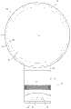
图1是风扇组件的前视图;Figure 1 is a front view of the fan assembly;
图2是图1的风扇组件的喷嘴的透视图;2 is a perspective view of a nozzle of the fan assembly of FIG. 1;
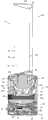
图3是图1的风扇组件的截面图;3 is a cross-sectional view of the fan assembly of FIG. 1;
图4是图3的一部分的放大视图;Figure 4 is an enlarged view of a portion of Figure 3;
图5(a)是图1的风扇组件的侧视图,显示出风扇组件处于不倾斜位置;Figure 5(a) is a side view of the fan assembly of Figure 1, showing the fan assembly in a non-tilted position;
图5(b)是图1的风扇组件的侧视图,显示出风扇组件处于第一倾斜位置;Figure 5(b) is a side view of the fan assembly of Figure 1, showing the fan assembly in a first tilted position;
图5(c)是图1的风扇组件的侧视图,显示出风扇组件处于第二倾斜位置;Figure 5(c) is a side view of the fan assembly of Figure 1, showing the fan assembly in a second tilted position;
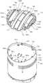
图6是图1的风扇组件的上基部构件的顶部透视图;6 is a top perspective view of the upper base member of the fan assembly of FIG. 1;
图7是图1的风扇组件的主体的后透视图;7 is a rear perspective view of the main body of the fan assembly of FIG. 1;
图8是图7的风扇组件的主体的分解视图;Figure 8 is an exploded view of the main body of the fan assembly of Figure 7;
图9(a)示出了风扇组件处于不倾斜位置时底座的两个截面图的路径;Figure 9(a) shows the path of two cross-sectional views of the base when the fan assembly is in the non-tilted position;
图9(b)是沿图9(a)中的线A-A截取的截面图;Figure 9(b) is a cross-sectional view taken along line A-A in Figure 9(a);
图9(c)是沿图9(a)中的线B-B截取的截面图;Figure 9(c) is a cross-sectional view taken along the line B-B in Figure 9(a);
图10(a)示出了风扇组件处于不倾斜位置时底座的两个另外的截面图的路径;Figure 10(a) shows the path of two additional cross-sectional views of the base with the fan assembly in the non-tilted position;
图10(b)是沿图10(a)中的线C-C截取的截面图;Figure 10(b) is a cross-sectional view taken along line C-C in Figure 10(a);
图10(c)是沿图10(a)中的线D-D截取的截面图;Figure 10(c) is a cross-sectional view taken along line D-D in Figure 10(a);
具体实施方式Detailed ways
图1是风扇组件的前视图。风扇组件10优选地具有无叶片风扇组件的形式,包括底座12和喷嘴14,该喷嘴14安装在底座12上并被其支撑。底座12包括大体柱形的外壳体16,该外壳体具有多个空气入口18,这些空气入口具有定位在外壳体16中的孔的形式且主气流通过该入口被从外部环境吸入底座12。底座12还包括多个用户可操作的按钮20和用户可操作的转盘22用于控制风扇组件10的运转。在该实例中,底座12具有从200到300mm范围的高度,且外壳体16具有从100到200mm范围的外直径。Figure 1 is a front view of the fan assembly. The
参考图2,喷嘴14具有环形形状并限定中心开口24。喷嘴14具有从200至400mm范围的高度。喷嘴14包括嘴部26,该嘴部朝向风扇组件10的后部定位用于发出来自风扇组件10的气流且使其穿过开口24。嘴部26至少部分地绕开口24延伸。喷嘴14的内周包括位于嘴部26附近的柯恩达表面28(嘴部26引导从风扇组件10发出的空气越过该表面)、位于柯恩达表面28下游的扩散表面30和位于扩散表面30下游的引导表面32。扩散表面30被设置为远离开口24的中心轴线X成锥形,由此有助于从风扇组件10发出的空气的流动。扩散表面30和开口24的中心轴线X之间的角度是在从5到25°的范围内,且在该实施例中为约15°。引导表面32被设置为相对于扩散表面30成一角度,以进一步帮助来自风扇组件10的冷却气流的有效传送。引导表面32优选地被设置为基本上平行于开口24的中心轴线X,以对于从嘴部26发出的气流呈现基本上平坦且基本上光滑的表面。视觉上引人注意的锥形表面34位于引导表面32的下游,结束于基本上垂直于开口24的中心轴线X的末端表面36处。锥形表面34和开口24的中心轴线X之间的角度优选地为约45°。喷嘴14在沿着开口24的中心轴线X延伸的方向上的总深度具有从100至150mm的范围,在本例中,大致为110mm。Referring to FIG. 2 , the
图3示出了穿过风扇组件10的截面视图。底座12包括基部和安装在该基部上的主体42,该基部由下基部构件38和位于下基部构件38上的上基部构件40形成。如图1和5所示,接口I形成在主体42和基部之间。该接口I具有弯曲、优选地波纹形外周。靠近该接口的至少基部和主体42的外表面由此具有大致相同的轮廓,在本实施例中为圆形。FIG. 3 shows a cross-sectional view through the
下基部构件38具有大致平坦的底表面43。上基部构件40容纳控制器44,用于响应图1和2中所示的用户可操作按钮26的下压和/或用户可操作转盘22的操纵,以控制风扇组件10的运转。上基部构件40还容纳摆动机构46,用于使上基部构件40和主体42相对于下基部构件38摆动。主体42的每个摆动循环的范围优选地在60°和120°之间,且在该实施例中为约90°。在该实施例中,摆动机构46被设置为每分钟执行约3到5个摆动循环。主电源电缆48穿过形成在下基部构件38中的孔延伸,以为风扇组件10供电。The
底座12的主体42具有敞开的上端,喷嘴14例如通过卡扣连接连接到该上端。主体42包括筒形栅格50,孔的阵列形成在其中以提供底座12的空气入口18。主体42容置叶轮52,用于抽吸主气流穿过栅格50的孔和进入底座12。优选地,叶轮52是混合流动式叶轮的形式。叶轮52连接到从马达56向外延伸的旋转轴54。在该实施例中,马达56是DC无刷马达,其速度通过控制器44响应用户对转盘22的操纵而改变。马达56的最大速度优选地从5000到10000rpm范围。马达56容置在马达座内,该马达座包括连接到下部部分60的上部部分58。马达座的上部部分58和下部部分60中的一个包括扩散器62,该扩散器为具有螺旋叶片的静止盘的形式且定位在叶轮52的下游。The
马达座定位在叶轮壳体64内且安装在其上。该叶轮壳体64安装在多个成角度间隔的支撑部66上,这些支撑部位于底座12的主体42内,在本例中,有三个支撑部,它们位于底座12的主体42内。大致为截头锥形的罩68定位在叶轮壳体64内。罩68成形为使得叶轮52的外边缘紧紧靠近罩68的内表面但并不与其接触。基本上环形的入口构件70连接到叶轮壳体64的底部,用于引导主气流进入叶轮壳体64。优选地,底座12还包括静音泡沫,用于降低从底座12发出的噪音。在该例中,底座12的主体42包括朝向主体42的基部定位的盘形泡沫构件72,和位于马达座内的基本环形的泡沫构件74。A motor mount is positioned within and mounted to impeller
图4示出了穿过喷嘴14的截面视图。喷嘴14包括环形外壳体段80,该段连接至环形内壳体段82并围绕其延伸。这些段的每个可由多个连接的部分形成,但在本例中,每个外壳体段80和内壳体段82由相应的单模制部分形成。内壳体段82限定了喷嘴14的中心开口24,且具有外周表面84,该外周表面成形为限定柯恩达表面28、扩散表面30、引导表面32和锥形表面34。FIG. 4 shows a sectional view through the
外壳体段80和内壳体段82一起限定喷嘴14的环形内部通道86。由此,内部通道86绕开口24延伸。内部通道86由外壳体段80的内周表面88和内壳体段82的内周表面90界定。外壳体段80包括底部92,该底部例如通过卡扣连接而连接至底座12的主体42的敞开上端并位于其上。外壳体段80的底部92包括孔,主气流通过该孔从底座12的主体42的敞开上端进入喷嘴14的内部通道86。Together, the
喷嘴14的嘴部26朝向风扇组件10的后部定位。嘴部26由外壳体段80的内周表面88和内壳体段82的外周表面84的相应的重叠的或面对的部分94、96限定。在该例中,嘴部26是基本上环形,如图4所示,当沿直径地穿过喷嘴14的线截取时具有基本上U形截面。在该例中,外壳体段80的内周表面88和内壳体段82的外周表面84的重叠部分94、96的形状被设置为使得嘴部26朝向出口98逐渐变细,该出口设置用于引导主气流流过柯恩达表面28上方。出口98是环形槽口的形式,优选地具有从0.5到5mm范围内的相对恒定的宽度。在该例中,出口98具有大约1.1mm的宽度。间隔件可间隔地设置在嘴部26周围,以使得外壳体段80的内周表面88和内壳体段82的外周表面84的重叠部分94、96间隔开,以保持出口98的宽度在期望的水平。这些间隔件可与外壳体段80的内周表面88或内壳体段82的外周表面84为整体。
现参考图5(a)、5(b)和5(c),主体42相对于底座12的基部可在如图5(b)所示的第一充分倾斜位置和如图5(c)所示的第二充分倾斜位置之间移动。当主体42从如图5(a)所示的不倾斜位置移动到两个充分倾斜位置中的一个时,该轴线X优选地倾斜有大约10°的角度。主体42和上基部构件40的外表面成形为使得,当主体42处于不倾斜位置时,基部和主体42的这些外表面的接合部分基本齐平。Referring now to Figures 5(a), 5(b) and 5(c), the base of the
参考图6,上基部构件40包括安装在下基部构件38上的环形下表面100、大致柱形的侧壁102和弯曲的上表面104。侧壁102包括多个孔106。用户可操作转盘22突出穿过其中一个孔106,而用户可操作按钮20可通过其他孔106接近。上基部构件40的弯曲上表面104是凹形的,且可描述为大致鞍形的。孔108形成在上基部构件40的上表面104上,用于接收从马达56延伸的电缆110(在图3中示出)。Referring to FIG. 6 ,
上基部构件40还包括四个支撑构件120,用于支撑上基部构件40上的主体42。支撑构件120从上基部构件40的上表面104向上突出,且被设置为使得,它们彼此基本等距且距上表面104的中心基本等距。第一对支撑构件120沿图9(a)指示的线B-B定位,且第二对支撑构件120与第一对支撑构件120平行。还参考图9(b)和9(c),每个支撑构件120包括柱形外壁122、敞开上端124和关闭下端126。支撑构件120的外壁122围绕滚珠轴承形式的滚动元件128。滚动元件128优选地具有比柱形外壁122的半径略小的半径,从而滚动元件128被支撑构件120保持且在其内可移动。滚动构件128通过弹性元件130被推动远离上基部构件40的上表面104,该弹性元件定位在支撑构件120的关闭下端126和滚动元件128之间,从而,滚动元件128的一部分突出超过支撑构件120的敞开上端124。在该例中,弹性构件130具有盘簧的形式。The
回到图6,上基部构件40还包括多个轨道,用于将主体42保持在上基部构件40上。轨道还用于引导主体42相对于上基部构件40的运动,从而当主体移离倾斜位置或移到倾斜位置时,主体42相对于上基部构件40基本没有扭动或旋转。每个轨道沿基本平行于轴线X的方向延伸。例如,其中一个轨道沿图10(a)指示的线D-D定位。在该例中,多个轨道包括一对相对长的内轨道140,其定位在一对相对短的外轨道142之间。还参考图9(b)和10(b),每个内轨道140具有倒L形的横截面,并包括壁144,该壁在相应对支撑构件120之间延伸,且连接至上基部构件40的上表面104并从该上表面竖立。每个内轨道140还包括弯曲凸缘146,其沿壁144的长度延伸且从壁144的顶部朝向相邻外引导轨道142垂直地突出。每个外轨道142也具有倒L形的横截面,并包括壁148和弯曲凸缘150,该壁连接至上基部构件40的上表面52并从该上表面竖立,该凸缘沿壁148的长度延伸且从壁148的顶部朝向相邻内引导轨道140垂直地突出。Referring back to FIG. 6 , the
参考图7和8,主体42包括大致柱形的侧壁160、环形下端162和弯曲基部164,该基部与主体42的下端162间隔开以限定凹部。栅格50优选地与侧壁160一体。主体42的侧壁160具有与上基部构件40的侧壁102大致相同的外直径。基部164为凸形的,且大致描述为具有倒鞍形的形状。孔166形成在基部164中,用于允许缆线110从主体42的基部164延伸。两对止挡构件168从基部164的周边向上延伸(如图8所示)。每对止挡构件168沿着一条线定位,该线沿大致平行于轴线X的方向延伸。例如,其中一对止挡构件168沿图10(a)所示的线D-D定位。7 and 8, the
凸状倾斜板170连接至主体42的基部164。倾斜板170定位在主体42的凹部内,且具有与主体42的基部164的曲率大致相同的曲率。每个止挡构件168突出穿过多个孔172的相应一个,所述多个孔172围绕倾斜板170的周边定位。倾斜板170成形为限定一对凸形滚道174,用于接合上基部构件40的滚动元件128。每个滚道174沿基本平行于轴线X的方向延伸,且被设置为接收相应对的支撑构件120的滚动元件128,如图9(c)所示。A convex sloped
倾斜板170还包括多个滑道,每个滑道设置为至少部分地定位在上基部构件40的相应轨道之下,且由此与该轨道协作,以将主体42保持在上基部构件40上,并引导主体42相对于上基部构件40的运动。由此,每个滑道沿大致平行于轴线X的方向延伸。例如,其中一个滑道沿图10(a)中指示的线D-D定位。在该例中,多个滑道包括一对相对长的、内滑道180,该对滑道位于一对相对短的、外滑道182之间。还参考图9(b)和10(b),每个内滑道180具有倒L形的横截面,且包括大致垂直的壁184和弯曲凸缘186,该凸缘从壁184的顶部的一部分垂直向内地突出。每个内滑道180的弯曲凸缘186的曲率与每个内轨道140的弯曲凸缘146的曲率大致相同。每个外滑道182具有倒L形的横截面,且包括大致垂直的壁188和弯曲凸缘190,该凸缘沿壁188的长度延伸且从壁188的顶部垂直向内地突出。同样,每个外滑道182的弯曲凸缘190的曲率与每个外轨道142的弯曲凸缘150的曲率大致相同。倾斜板170还包括孔192用于接收缆线110。
为了将主体42连接至上基部构件40,倾斜板170与图7和8所示的方位颠倒,且倾斜板的滚道174直接定位在上基部构件40的支撑构件120之后且与其成一直线。延伸穿过主体42的孔166的缆线110分别旋拧穿过倾斜板170和上基部构件40中的孔108、192,用于随后连接至控制器44,如图3所示。然后,倾斜板170在上基部构件40上滑动,从而滚动元件128接合滚道174,如图9(b)和9(c)所示,每个外滑道182的弯曲凸缘190定位在相应外轨道142的弯曲凸缘150之下,如图9(b)和10(b)所示,每个内滑道180的弯曲凸缘186定位在相应内轨道140的弯曲凸缘146之下,如图9(b)、10(b)和10(c)所示。To connect the
当倾斜板170居中地定位在上基部构件40上时,主体42降低到倾斜板170上,从而止挡构件168定位在倾斜板170的孔172内,倾斜板170容纳在主体42的凹部内。上基部构件42和主体42然后颠倒,沿轴线X的方向移位的基部构件40使定位在倾斜板170上的多个第一孔194a显露。每个这些孔194a与主体42的基部164上的管状突出部196a对准。自攻丝螺钉旋拧到每个孔194a中,以进入下面的突出部196a,由此将倾斜板170部分地连接至主体42。上基部构件40然后沿相反方向移位,以使定位在倾斜板170上的多个第二孔194b显露。每个这些孔194b也与主体42的基部164上的管状突出部196b对准。自攻丝螺钉旋拧到每个孔194b中,以进入下面的突出部196b,由此将倾斜板170完全地连接至主体42。When the
当主体42附连至定位在支撑表面上的下基部构件38的底表面43和基部时,主体42被支撑构件120的滚动元件128支撑。支撑构件120的弹性元件130使滚动元件128远离支撑构件120的关闭下端126一距离,该距离足以防止在主体42倾斜时上基部构件40的上表面的刮擦。例如,如图9(b)、9(c)、10(b)和10(c)的每个所示,主体42的下端162被推动远离上基部构件40的上表面104,以防止在主体42倾斜时它们之间接触。此外,弹性元件130的动作推动滑道的弯曲凸缘186、190的凹形上表面抵靠轨道的弯曲凸缘146、150的凸形下表面。The
为了使主体42相对于基部倾斜,使用者沿大致平行于轴线X的方向滑动主体42,以将主体42朝向图5(b)和5(c)所示的其中一个充分倾斜位置移动,导致滚动元件128沿滚道174移动。一旦主体42处于期望位置时,使用者释放主体42,主体通过摩擦力保持在期望位置中,该摩擦力通过滑道的弯曲凸缘186、190的凹形上表面和轨道的弯曲凸缘146、150的凸形下表面之间的接触产生并作用于防止在主体42的重力下朝向图5(a)所示不倾斜位置的移动。主体42的充分倾斜位置通过每对止挡构件168中的一个与相应内轨道140的邻接而限定。To tilt the
为了操作风扇组件10,使用者按压底座12上的按钮20中的适当的一个,响应该按压,控制器44启动马达56以旋转叶轮52。叶轮52的旋转导致主气流通过空气入口18被抽入底座12。依赖于马达56的速度,主气流流速可在20和30升每秒之间。主气流相继穿过叶轮壳体64和主体42的敞开上端以进入喷嘴14的内部通道86。在喷嘴14内,主气流被分成两股气流,其沿相反方向绕喷嘴14的中心开口24通过。当气流穿过内部通道86时,空气进入喷嘴14的嘴部26。进入嘴部26的气流优选地绕喷嘴14的开口24基本上是均匀的。在嘴部26的每部分内,所述气流部分的流动方向被基本反向。所述气流部分受到嘴部26的锥形部分的约束且通过出口98发出。To operate
从嘴部26发出的主气流被引导流过喷嘴14的柯恩达表面28上方,通过来自外部环境(具体地来自嘴部26的出口98周围区域和来自喷嘴14的后部附近)的空气的夹带导致产生二次气流。该二次气流穿过喷嘴14的中心开口24,在那里与主气流合并以产生总气流,或空气流,从喷嘴14向前投射。依赖于马达56的速度,从风扇组件10向前投射的空气流的质量流速可高达400升每秒,优选地高达600升每秒,且空气流的最大速度可在2.5到4.5m/s的范围内。The primary airflow emanating from the
主气流沿喷嘴14的嘴部26的均匀分布确保气流在扩散表面30上均匀地经过。通过将气流移动穿过受控膨胀区域,扩散表面30导致气流的平均速度降低。扩散表面30的相对于开口38的中心轴线X相对较小的角度允许气流的膨胀逐渐地发生。否则,急剧或快速发散将导致气流变得混乱,在膨胀区域中产生旋涡。这种旋涡可导致气流中湍流和相关联噪音的增加,这是不希望的,特别是在例如风扇的家用电器中。向前投射越过扩散表面30的气流可倾向于连续地发散。基本上平行于开口30的中心轴线X延伸的引导表面32的存在进一步会聚该气流。结果,气流可有效地行进从喷嘴14出来,使得气流可在离风扇组件10几米距离处被快速体验到。The uniform distribution of the primary airflow along the
本发明并不限于上述给出的具体描述。变体对本领域的技术人员是明显的。例如,底座12可用于除了风扇组件的其它装置。主体42相对于基部的运动可被用户通过按下其中一个按钮20而启动和促动。The invention is not limited to the specific description given above. Variants will be apparent to those skilled in the art. For example,
Claims (43)
Translated fromChineseApplications Claiming Priority (2)
| Application Number | Priority Date | Filing Date | Title |
|---|---|---|---|
| GB0903679.9 | 2009-03-04 | ||
| GB0903679AGB2468322B (en) | 2009-03-04 | 2009-03-04 | Tilting fan stand |
Related Parent Applications (1)
| Application Number | Title | Priority Date | Filing Date |
|---|---|---|---|
| CN2010101299991ADivisionCN101825104B (en) | 2009-03-04 | 2010-03-04 | Fan assembly |
Publications (2)
| Publication Number | Publication Date |
|---|---|
| CN102493960Atrue CN102493960A (en) | 2012-06-13 |
| CN102493960B CN102493960B (en) | 2014-09-10 |
Family
ID=40580576
Family Applications (4)
| Application Number | Title | Priority Date | Filing Date |
|---|---|---|---|
| CN2010900005439UExpired - LifetimeCN201917047U (en) | 2009-03-04 | 2010-02-18 | Fan assembly and base for the fan assembly |
| CN201110408390.2AExpired - Fee RelatedCN102425575B (en) | 2009-03-04 | 2010-03-04 | Fan component |
| CN2010101299991AActiveCN101825104B (en) | 2009-03-04 | 2010-03-04 | Fan assembly |
| CN201110409259.8AExpired - Fee RelatedCN102493960B (en) | 2009-03-04 | 2010-03-04 | A fan assembly |
Family Applications Before (3)
| Application Number | Title | Priority Date | Filing Date |
|---|---|---|---|
| CN2010900005439UExpired - LifetimeCN201917047U (en) | 2009-03-04 | 2010-02-18 | Fan assembly and base for the fan assembly |
| CN201110408390.2AExpired - Fee RelatedCN102425575B (en) | 2009-03-04 | 2010-03-04 | Fan component |
| CN2010101299991AActiveCN101825104B (en) | 2009-03-04 | 2010-03-04 | Fan assembly |
Country Status (19)
| Country | Link |
|---|---|
| US (3) | US9513028B2 (en) |
| EP (4) | EP2404119B1 (en) |
| JP (5) | JP4861492B2 (en) |
| KR (5) | KR101278525B1 (en) |
| CN (4) | CN201917047U (en) |
| AU (4) | AU2010219486B2 (en) |
| BR (1) | BRPI1005520A2 (en) |
| CA (4) | CA2832668C (en) |
| DK (4) | DK2404119T3 (en) |
| ES (4) | ES2527016T3 (en) |
| GB (3) | GB2468322B (en) |
| IL (1) | IL214152A (en) |
| MY (2) | MY144197A (en) |
| NZ (1) | NZ593319A (en) |
| PL (1) | PL2404119T3 (en) |
| RU (3) | RU2489652C2 (en) |
| SG (2) | SG172637A1 (en) |
| WO (1) | WO2010100451A1 (en) |
| ZA (1) | ZA201107218B (en) |
Cited By (2)
| Publication number | Priority date | Publication date | Assignee | Title |
|---|---|---|---|---|
| CN103541886A (en)* | 2012-07-11 | 2014-01-29 | 戴森技术有限公司 | Fan assembly |
| CN104279145A (en)* | 2013-07-09 | 2015-01-14 | 戴森技术有限公司 | Fan assembly |
Families Citing this family (123)
| Publication number | Priority date | Publication date | Assignee | Title |
|---|---|---|---|---|
| GB0814835D0 (en) | 2007-09-04 | 2008-09-17 | Dyson Technology Ltd | A Fan |
| GB2463698B (en) | 2008-09-23 | 2010-12-01 | Dyson Technology Ltd | A fan |
| GB2464736A (en) | 2008-10-25 | 2010-04-28 | Dyson Technology Ltd | Fan with a filter |
| GB2466058B (en)* | 2008-12-11 | 2010-12-22 | Dyson Technology Ltd | Fan nozzle with spacers |
| GB2468312A (en) | 2009-03-04 | 2010-09-08 | Dyson Technology Ltd | Fan assembly |
| GB2468322B (en) | 2009-03-04 | 2011-03-16 | Dyson Technology Ltd | Tilting fan stand |
| GB0903682D0 (en) | 2009-03-04 | 2009-04-15 | Dyson Technology Ltd | A fan |
| GB2468320C (en) | 2009-03-04 | 2011-06-01 | Dyson Technology Ltd | Tilting fan |
| CN202056982U (en) | 2009-03-04 | 2011-11-30 | 戴森技术有限公司 | Humidifying device |
| GB2468326A (en) | 2009-03-04 | 2010-09-08 | Dyson Technology Ltd | Telescopic pedestal fan |
| GB2468323A (en) | 2009-03-04 | 2010-09-08 | Dyson Technology Ltd | Fan assembly |
| PL2276933T3 (en) | 2009-03-04 | 2011-10-31 | Dyson Technology Ltd | A fan |
| GB2468317A (en) | 2009-03-04 | 2010-09-08 | Dyson Technology Ltd | Height adjustable and oscillating fan |
| GB2468329A (en) | 2009-03-04 | 2010-09-08 | Dyson Technology Ltd | Fan assembly |
| GB2468331B (en) | 2009-03-04 | 2011-02-16 | Dyson Technology Ltd | A fan |
| NZ593318A (en) | 2009-03-04 | 2012-11-30 | Dyson Technology Ltd | An annular fan assembly with a silencing member |
| GB2468325A (en)* | 2009-03-04 | 2010-09-08 | Dyson Technology Ltd | Height adjustable fan with nozzle |
| GB2468315A (en) | 2009-03-04 | 2010-09-08 | Dyson Technology Ltd | Tilting fan |
| KR101395177B1 (en) | 2009-03-04 | 2014-05-15 | 다이슨 테크놀러지 리미티드 | A fan |
| GB0919473D0 (en) | 2009-11-06 | 2009-12-23 | Dyson Technology Ltd | A fan |
| GB2478927B (en) | 2010-03-23 | 2016-09-14 | Dyson Technology Ltd | Portable fan with filter unit |
| GB2478925A (en) | 2010-03-23 | 2011-09-28 | Dyson Technology Ltd | External filter for a fan |
| SG186071A1 (en) | 2010-05-27 | 2013-01-30 | Dyson Technology Ltd | Device for blowing air by means of narrow slit nozzle assembly |
| GB2482548A (en) | 2010-08-06 | 2012-02-08 | Dyson Technology Ltd | A fan assembly with a heater |
| GB2482549A (en) | 2010-08-06 | 2012-02-08 | Dyson Technology Ltd | A fan assembly with a heater |
| GB2482547A (en) | 2010-08-06 | 2012-02-08 | Dyson Technology Ltd | A fan assembly with a heater |
| GB2483448B (en) | 2010-09-07 | 2015-12-02 | Dyson Technology Ltd | A fan |
| JP5588565B2 (en) | 2010-10-13 | 2014-09-10 | ダイソン テクノロジー リミテッド | Blower assembly |
| GB2484670B (en) | 2010-10-18 | 2018-04-25 | Dyson Technology Ltd | A fan assembly |
| EP2630373B1 (en) | 2010-10-18 | 2016-12-28 | Dyson Technology Limited | A fan assembly |
| JP5548581B2 (en)* | 2010-10-22 | 2014-07-16 | パナソニック株式会社 | Mist generator and beauty device provided with the same |
| JP5778293B2 (en) | 2010-11-02 | 2015-09-16 | ダイソン テクノロジー リミテッド | Blower assembly |
| GB2486019B (en) | 2010-12-02 | 2013-02-20 | Dyson Technology Ltd | A fan |
| GB2486890B (en)* | 2010-12-23 | 2017-09-06 | Dyson Technology Ltd | A fan |
| CN102777430A (en)* | 2011-05-12 | 2012-11-14 | 任文华 | Fan |
| CN102200144A (en)* | 2011-06-23 | 2011-09-28 | 周云飞 | Bladeless fan |
| CN102322427B (en)* | 2011-06-25 | 2013-02-13 | 应辉 | Fan assembly |
| BR112014001474A2 (en) | 2011-07-27 | 2017-02-21 | Dyson Technology Ltd | fan assembly |
| GB2493506B (en) | 2011-07-27 | 2013-09-11 | Dyson Technology Ltd | A fan assembly |
| US8899378B2 (en) | 2011-09-13 | 2014-12-02 | Black & Decker Inc. | Compressor intake muffler and filter |
| AU2012216659B2 (en) | 2011-09-13 | 2016-03-24 | Black & Decker Inc | Air ducting shroud for cooling an air compressor pump and motor |
| GB201119500D0 (en)* | 2011-11-11 | 2011-12-21 | Dyson Technology Ltd | A fan assembly |
| GB2496877B (en) | 2011-11-24 | 2014-05-07 | Dyson Technology Ltd | A fan assembly |
| GB2498547B (en) | 2012-01-19 | 2015-02-18 | Dyson Technology Ltd | A fan |
| GB2499042A (en) | 2012-02-06 | 2013-08-07 | Dyson Technology Ltd | A nozzle for a fan assembly |
| GB2499041A (en) | 2012-02-06 | 2013-08-07 | Dyson Technology Ltd | Bladeless fan including an ionizer |
| GB2499044B (en) | 2012-02-06 | 2014-03-19 | Dyson Technology Ltd | A fan |
| DE102012100974B4 (en)* | 2012-02-07 | 2013-10-10 | Stego-Holding Gmbh | Fan and arrangement having such a fan |
| GB2512192B (en) | 2012-03-06 | 2015-08-05 | Dyson Technology Ltd | A Humidifying Apparatus |
| GB2500012B (en) | 2012-03-06 | 2016-07-06 | Dyson Technology Ltd | A Humidifying Apparatus |
| RU2606194C2 (en) | 2012-03-06 | 2017-01-10 | Дайсон Текнолоджи Лимитед | Fan unit |
| GB2500011B (en) | 2012-03-06 | 2016-07-06 | Dyson Technology Ltd | A Humidifying Apparatus |
| GB2500010B (en) | 2012-03-06 | 2016-08-24 | Dyson Technology Ltd | A humidifying apparatus |
| GB2500017B (en) | 2012-03-06 | 2015-07-29 | Dyson Technology Ltd | A Humidifying Apparatus |
| GB2500903B (en) | 2012-04-04 | 2015-06-24 | Dyson Technology Ltd | Heating apparatus |
| CN102661295B (en)* | 2012-04-10 | 2014-12-31 | 宁波宏钜电器科技有限公司 | Base component of bladeless fan |
| GB2501301B (en) | 2012-04-19 | 2016-02-03 | Dyson Technology Ltd | A fan assembly |
| GB2532557B (en) | 2012-05-16 | 2017-01-11 | Dyson Technology Ltd | A fan comprsing means for suppressing noise |
| EP2850324A2 (en) | 2012-05-16 | 2015-03-25 | Dyson Technology Limited | A fan |
| GB2518935B (en) | 2012-05-16 | 2016-01-27 | Dyson Technology Ltd | A fan |
| CN102889239A (en)* | 2012-11-02 | 2013-01-23 | 李起武 | Fan |
| CN102889233A (en)* | 2012-11-02 | 2013-01-23 | 李起武 | Fan |
| AU350181S (en) | 2013-01-18 | 2013-08-15 | Dyson Technology Ltd | Humidifier or fan |
| AU350179S (en) | 2013-01-18 | 2013-08-15 | Dyson Technology Ltd | Humidifier or fan |
| AU350140S (en) | 2013-01-18 | 2013-08-13 | Dyson Technology Ltd | Humidifier or fan |
| BR302013003358S1 (en) | 2013-01-18 | 2014-11-25 | Dyson Technology Ltd | CONFIGURATION APPLIED ON HUMIDIFIER |
| GB2510195B (en) | 2013-01-29 | 2016-04-27 | Dyson Technology Ltd | A fan assembly |
| SG11201505665RA (en) | 2013-01-29 | 2015-08-28 | Dyson Technology Ltd | A fan assembly |
| CA152658S (en) | 2013-03-07 | 2014-05-20 | Dyson Technology Ltd | Fan |
| CA152657S (en) | 2013-03-07 | 2014-05-20 | Dyson Technology Ltd | Fan |
| CA152656S (en) | 2013-03-07 | 2014-05-20 | Dyson Technology Ltd | Fan |
| USD729372S1 (en) | 2013-03-07 | 2015-05-12 | Dyson Technology Limited | Fan |
| CA152655S (en) | 2013-03-07 | 2014-05-20 | Dyson Technology Ltd | Fan |
| BR302013004394S1 (en) | 2013-03-07 | 2014-12-02 | Dyson Technology Ltd | CONFIGURATION APPLIED TO FAN |
| GB2536767B (en)* | 2013-03-11 | 2017-11-15 | Dyson Technology Ltd | A fan assembly nozzle with control port |
| USD730510S1 (en) | 2013-05-14 | 2015-05-26 | Stego-Holding Gmbh | Air vent |
| CN103453637B (en)* | 2013-06-03 | 2015-09-02 | 海尔集团公司 | Air-conditioner air supply device and there is the air-conditioning of this device |
| CN103453636B (en)* | 2013-06-03 | 2015-09-02 | 海尔集团公司 | Air-conditioner air supply device and air-conditioning |
| CA154722S (en) | 2013-08-01 | 2015-02-16 | Dyson Technology Ltd | Fan |
| CA154723S (en) | 2013-08-01 | 2015-02-16 | Dyson Technology Ltd | Fan |
| TWD172707S (en) | 2013-08-01 | 2015-12-21 | 戴森科技有限公司 | A fan |
| GB2518638B (en) | 2013-09-26 | 2016-10-12 | Dyson Technology Ltd | Humidifying apparatus |
| JP1518058S (en)* | 2014-01-09 | 2015-02-23 | ||
| JP1518059S (en)* | 2014-01-09 | 2015-02-23 | ||
| GB2528709B (en) | 2014-07-29 | 2017-02-08 | Dyson Technology Ltd | Humidifying apparatus |
| GB2528708B (en) | 2014-07-29 | 2016-06-29 | Dyson Technology Ltd | A fan assembly |
| GB2528704A (en) | 2014-07-29 | 2016-02-03 | Dyson Technology Ltd | Humidifying apparatus |
| US9657742B2 (en)* | 2014-09-15 | 2017-05-23 | Speedtech Energy Co., Ltd. | Solar fan |
| CN104895768A (en)* | 2014-12-18 | 2015-09-09 | 任文华 | Fan assembly and nozzle for fan assembly |
| US11111913B2 (en) | 2015-10-07 | 2021-09-07 | Black & Decker Inc. | Oil lubricated compressor |
| CN105351230B (en)* | 2015-12-10 | 2017-11-28 | 南华大学 | Coanda fin ventilation fan |
| DE102015122491A1 (en) | 2015-12-22 | 2017-06-22 | Volkswagen Aktiengesellschaft | Cooling system and motor vehicle |
| EP3458719B1 (en)* | 2016-05-18 | 2020-05-13 | De' Longhi Appliances S.r.l. Con Unico Socio | Fan |
| WO2018175359A1 (en) | 2017-03-20 | 2018-09-27 | Shop Vac Corporation | Axial fan having housing formed by connectable pieces and including air guide ribs and an internal ramp |
| US11384956B2 (en) | 2017-05-22 | 2022-07-12 | Sharkninja Operating Llc | Modular fan assembly with articulating nozzle |
| CN107575407B (en)* | 2017-09-30 | 2023-11-03 | 广东美的环境电器制造有限公司 | Bladeless fan and handpiece for a bladeless fan |
| GB2568938B (en) | 2017-12-01 | 2020-12-30 | Dyson Technology Ltd | A filter assembly |
| GB2568937B (en) | 2017-12-01 | 2020-08-12 | Dyson Technology Ltd | A fan assembly |
| GB2568979A (en)* | 2017-12-01 | 2019-06-05 | Dyson Technology Ltd | A fan assembly |
| GB2568939B (en) | 2017-12-01 | 2020-12-02 | Dyson Technology Ltd | A fan assembly |
| CN108119379B (en)* | 2018-01-16 | 2024-04-23 | 浙江弩牌电器有限公司 | Air supply device |
| GB2571718B (en) | 2018-03-05 | 2020-12-16 | Dyson Technology Ltd | A fan assembly |
| GB2571717B (en) | 2018-03-05 | 2020-12-16 | Dyson Technology Ltd | A fan assembly |
| WO2019191237A1 (en)* | 2018-03-29 | 2019-10-03 | Walmart Apollo, Llc | Aerial vehicle turbine system |
| US11300128B2 (en)* | 2018-05-11 | 2022-04-12 | Hubbell Incorporated | Bladeless ceiling fan |
| GB2575065B (en) | 2018-06-27 | 2021-03-24 | Dyson Technology Ltd | A nozzle for a fan assembly |
| GB2575063B (en) | 2018-06-27 | 2021-06-09 | Dyson Technology Ltd | A nozzle for a fan assembly |
| GB2575064B (en) | 2018-06-27 | 2021-06-09 | Dyson Technology Ltd | A nozzle for a fan assembly |
| GB2575066B (en) | 2018-06-27 | 2020-11-25 | Dyson Technology Ltd | A nozzle for a fan assembly |
| GB2578616B (en) | 2018-11-01 | 2021-02-24 | Dyson Technology Ltd | A nozzle for a fan assembly |
| GB2578617B (en) | 2018-11-01 | 2021-02-24 | Dyson Technology Ltd | A nozzle for a fan assembly |
| GB2578615B (en) | 2018-11-01 | 2021-10-13 | Dyson Technology Ltd | A fan assembly |
| GB201900025D0 (en) | 2019-01-02 | 2019-02-13 | Dyson Technology Ltd | A fan assembly |
| GB2582796B (en) | 2019-04-03 | 2021-11-03 | Dyson Technology Ltd | Control of a fan assembly |
| US11167855B2 (en)* | 2019-04-30 | 2021-11-09 | Rohr, Inc. | Method and apparatus for aircraft anti-icing |
| US11465758B2 (en) | 2019-04-30 | 2022-10-11 | Rohr, Inc. | Method and apparatus for aircraft anti-icing |
| EP4063667B1 (en)* | 2019-11-18 | 2024-08-28 | Ying, Hui | Fan |
| US11378100B2 (en) | 2020-11-30 | 2022-07-05 | E. Mishan & Sons, Inc. | Oscillating portable fan with removable grille |
| GB2608124B (en) | 2021-06-22 | 2023-11-15 | Dyson Technology Ltd | Nozzle for a fan assembly |
| GB2619527A (en) | 2022-06-07 | 2023-12-13 | Jones Food Company Ltd | Vertical farming system |
| US12161949B2 (en)* | 2022-08-05 | 2024-12-10 | Lizhen Lin | Bubble machine with adjustable blowing angle |
| US20240245190A1 (en) | 2023-01-19 | 2024-07-25 | Sharkninja Operating Llc | Identification of hair care appliance attachments |
| US20250213029A1 (en) | 2023-01-19 | 2025-07-03 | Sharkninja Operating Llc | Hair care appliance with powered attachment |
Citations (4)
| Publication number | Priority date | Publication date | Assignee | Title |
|---|---|---|---|---|
| US4703152A (en)* | 1985-12-11 | 1987-10-27 | Holmes Products Corp. | Tiltable and adjustably oscillatable portable electric heater/fan |
| US5310313A (en)* | 1992-11-23 | 1994-05-10 | Chen C H | Swinging type of electric fan |
| US5518370A (en)* | 1995-04-03 | 1996-05-21 | Duracraft Corporation | Portable electric fan with swivel mount |
| CN1037122C (en)* | 1994-05-07 | 1998-01-21 | 陈正和 | Oscillating fan |
Family Cites Families (427)
| Publication number | Priority date | Publication date | Assignee | Title |
|---|---|---|---|---|
| US751485A (en)* | 1904-02-09 | Chaeles a | ||
| GB601222A (en) | 1944-10-04 | 1948-04-30 | Berkeley & Young Ltd | Improvements in, or relating to, electric fans |
| GB593828A (en) | 1945-06-14 | 1947-10-27 | Dorothy Barker | Improvements in or relating to propeller fans |
| US1357261A (en) | 1918-10-02 | 1920-11-02 | Ladimir H Svoboda | Fan |
| US1767060A (en) | 1928-10-04 | 1930-06-24 | W H Addington | Electric motor-driven desk fan |
| US2014185A (en) | 1930-06-25 | 1935-09-10 | Martin Brothers Electric Compa | Drier |
| GB383498A (en) | 1931-03-03 | 1932-11-17 | Spontan Ab | Improvements in or relating to fans, ventilators, or the like |
| US1896869A (en)* | 1931-07-18 | 1933-02-07 | Master Electric Co | Electric fan |
| US2035733A (en)* | 1935-06-10 | 1936-03-31 | Marathon Electric Mfg | Fan motor mounting |
| US2210458A (en) | 1936-11-16 | 1940-08-06 | Lester S Keilholtz | Method of and apparatus for air conditioning |
| US2115883A (en)* | 1937-04-21 | 1938-05-03 | Sher Samuel | Lamp |
| US2258961A (en) | 1939-07-26 | 1941-10-14 | Prat Daniel Corp | Ejector draft control |
| US2336295A (en) | 1940-09-25 | 1943-12-07 | Reimuller Caryl | Air diverter |
| GB641622A (en) | 1942-05-06 | 1950-08-16 | Fernan Oscar Conill | Improvements in or relating to hair drying |
| US2433795A (en) | 1945-08-18 | 1947-12-30 | Westinghouse Electric Corp | Fan |
| US2476002A (en)* | 1946-01-12 | 1949-07-12 | Edward A Stalker | Rotating wing |
| US2547448A (en)* | 1946-02-20 | 1951-04-03 | Demuth Charles | Hot-air space heater |
| US2473325A (en)* | 1946-09-19 | 1949-06-14 | E A Lab Inc | Combined electric fan and air heating means |
| US2544379A (en)* | 1946-11-15 | 1951-03-06 | Oscar J Davenport | Ventilating apparatus |
| US2488467A (en)* | 1947-09-12 | 1949-11-15 | Lisio Salvatore De | Motor-driven fan |
| GB633273A (en) | 1948-02-12 | 1949-12-12 | Albert Richard Ponting | Improvements in or relating to air circulating apparatus |
| US2510132A (en)* | 1948-05-27 | 1950-06-06 | Morrison Hackley | Oscillating fan |
| GB661747A (en) | 1948-12-18 | 1951-11-28 | British Thomson Houston Co Ltd | Improvements in and relating to oscillating fans |
| US2620127A (en) | 1950-02-28 | 1952-12-02 | Westinghouse Electric Corp | Air translating apparatus |
| US2583374A (en)* | 1950-10-18 | 1952-01-22 | Hydraulic Supply Mfg Company | Exhaust fan |
| FR1033034A (en)* | 1951-02-23 | 1953-07-07 | Articulated stabilizer support for fan with flexible propellers and variable speeds | |
| US2813673A (en) | 1953-07-09 | 1957-11-19 | Gilbert Co A C | Tiltable oscillating fan |
| US2838229A (en)* | 1953-10-30 | 1958-06-10 | Roland J Belanger | Electric fan |
| US2765977A (en) | 1954-10-13 | 1956-10-09 | Morrison Hackley | Electric ventilating fans |
| FR1119439A (en) | 1955-02-18 | 1956-06-20 | Enhancements to portable and wall fans | |
| US2830779A (en)* | 1955-02-21 | 1958-04-15 | Lau Blower Co | Fan stand |
| NL110393C (en)* | 1955-11-29 | 1965-01-15 | Bertin & Cie | |
| CH346643A (en) | 1955-12-06 | 1960-05-31 | K Tateishi Arthur | Electric fan |
| US2808198A (en) | 1956-04-30 | 1957-10-01 | Morrison Hackley | Oscillating fans |
| GB863124A (en) | 1956-09-13 | 1961-03-15 | Sebac Nouvelle Sa | New arrangement for putting gases into movement |
| BE560119A (en) | 1956-09-13 | |||
| US2922570A (en)* | 1957-12-04 | 1960-01-26 | Burris R Allen | Automatic booster fan and ventilating shield |
| US3004403A (en) | 1960-07-21 | 1961-10-17 | Francis L Laporte | Refrigerated space humidification |
| DE1291090B (en) | 1963-01-23 | 1969-03-20 | Schmidt Geb Halm Anneliese | Device for generating an air flow |
| DE1457461A1 (en) | 1963-10-01 | 1969-02-20 | Siemens Elektrogeraete Gmbh | Suitcase-shaped hair dryer |
| FR1387334A (en) | 1963-12-21 | 1965-01-29 | Hair dryer capable of blowing hot and cold air separately | |
| US3204898A (en)* | 1964-02-17 | 1965-09-07 | Product Engineering Company | Adjustable support |
| US3270655A (en) | 1964-03-25 | 1966-09-06 | Howard P Guirl | Air curtain door seal |
| US3518776A (en)* | 1967-06-03 | 1970-07-07 | Bremshey & Co | Blower,particularly for hair-drying,laundry-drying or the like |
| US3444817A (en) | 1967-08-23 | 1969-05-20 | William J Caldwell | Fluid pump |
| US3487555A (en) | 1968-01-15 | 1970-01-06 | Hoover Co | Portable hair dryer |
| US3495343A (en) | 1968-02-20 | 1970-02-17 | Rayette Faberge | Apparatus for applying air and vapor to the face and hair |
| US3503138A (en)* | 1969-05-19 | 1970-03-31 | Oster Mfg Co John | Hair dryer |
| GB1278606A (en) | 1969-09-02 | 1972-06-21 | Oberlind Veb Elektroinstall | Improvements in or relating to transverse flow fans |
| US3645007A (en) | 1970-01-14 | 1972-02-29 | Sunbeam Corp | Hair dryer and facial sauna |
| DK122977B (en)* | 1970-07-10 | 1972-05-01 | Nordisk Ventilator | Axial fan whose impeller has adjustable blades during operation. |
| DE2944027A1 (en) | 1970-07-22 | 1981-05-07 | Erevanskyj politechničeskyj institut imeni Karla Marksa, Erewan | EJECTOR ROOM AIR CONDITIONER OF THE CENTRAL AIR CONDITIONING |
| US3724092A (en)* | 1971-07-12 | 1973-04-03 | Westinghouse Electric Corp | Portable hair dryer |
| GB1403188A (en) | 1971-10-22 | 1975-08-28 | Olin Energy Systems Ltd | Fluid flow inducing apparatus |
| JPS517258Y2 (en) | 1971-11-15 | 1976-02-27 | ||
| US3743186A (en)* | 1972-03-14 | 1973-07-03 | Src Lab | Air gun |
| US3885891A (en)* | 1972-11-30 | 1975-05-27 | Rockwell International Corp | Compound ejector |
| US3795367A (en)* | 1973-04-05 | 1974-03-05 | Src Lab | Fluid device using coanda effect |
| US3872916A (en)* | 1973-04-05 | 1975-03-25 | Int Harvester Co | Fan shroud exit structure |
| JPS49150403U (en) | 1973-04-23 | 1974-12-26 | ||
| US4037991A (en)* | 1973-07-26 | 1977-07-26 | The Plessey Company Limited | Fluid-flow assisting devices |
| US3875745A (en)* | 1973-09-10 | 1975-04-08 | Wagner Minning Equipment Inc | Venturi exhaust cooler |
| GB1434226A (en) | 1973-11-02 | 1976-05-05 | Roberts S A | Pumps |
| US3943329A (en)* | 1974-05-17 | 1976-03-09 | Clairol Incorporated | Hair dryer with safety guard air outlet nozzle |
| CA1055344A (en) | 1974-05-17 | 1979-05-29 | International Harvester Company | Heat transfer system employing a coanda effect producing fan shroud exit |
| US4184541A (en)* | 1974-05-22 | 1980-01-22 | International Harvester Company | Heat exchange apparatus including a toroidal-type radiator |
| US4180130A (en)* | 1974-05-22 | 1979-12-25 | International Harvester Company | Heat exchange apparatus including a toroidal-type radiator |
| GB1501473A (en) | 1974-06-11 | 1978-02-15 | Charbonnages De France | Fans |
| GB1495013A (en)* | 1974-06-25 | 1977-12-14 | British Petroleum Co | Coanda unit |
| GB1593391A (en)* | 1977-01-28 | 1981-07-15 | British Petroleum Co | Flare |
| JPS517258U (en) | 1974-07-01 | 1976-01-20 | ||
| JPS517258A (en)* | 1974-07-11 | 1976-01-21 | Tsudakoma Ind Co Ltd | YOKOITO CHORYUSOCHI |
| DE2451557C2 (en) | 1974-10-30 | 1984-09-06 | Arnold Dipl.-Ing. 8904 Friedberg Scheel | Device for ventilating a occupied zone in a room |
| US4136735A (en)* | 1975-01-24 | 1979-01-30 | International Harvester Company | Heat exchange apparatus including a toroidal-type radiator |
| US4061188A (en)* | 1975-01-24 | 1977-12-06 | International Harvester Company | Fan shroud structure |
| US4173995A (en)* | 1975-02-24 | 1979-11-13 | International Harvester Company | Recirculation barrier for a heat transfer system |
| US4332529A (en)* | 1975-08-11 | 1982-06-01 | Morton Alperin | Jet diffuser ejector |
| US4046492A (en) | 1976-01-21 | 1977-09-06 | Vortec Corporation | Air flow amplifier |
| JPS531015A (en) | 1976-06-25 | 1978-01-07 | Nippon Gakki Seizo Kk | Electronic musical instrument |
| JPS5351608A (en) | 1976-10-20 | 1978-05-11 | Asahi Giken Kk | Fluid conveying tube to be installed under the water surface |
| JPS5531911Y2 (en) | 1976-10-25 | 1980-07-30 | ||
| DK140426B (en) | 1976-11-01 | 1979-08-27 | Arborg O J M | Propulsion nozzle for means of transport in air or water. |
| US4113416A (en) | 1977-02-24 | 1978-09-12 | Ishikawajima-Harima Jukogyo Kabushiki Kaisha | Rotary burner |
| JPS56148100A (en) | 1980-04-21 | 1981-11-17 | Tokyo Shibaura Electric Co | Pipe through device of nuclear reactor container |
| JPS5719995Y2 (en) | 1980-05-13 | 1982-04-27 | ||
| JPS56167897A (en)* | 1980-05-28 | 1981-12-23 | Toshiba Corp | Fan |
| AU7279281A (en) | 1980-07-17 | 1982-01-21 | General Conveyors Ltd. | Variable nozzle for jet pump |
| JPS5771000U (en) | 1980-10-20 | 1982-04-30 | ||
| MX147915A (en) | 1981-01-30 | 1983-01-31 | Philips Mexicana S A De C V | ELECTRIC FAN |
| JPS57157097A (en)* | 1981-03-20 | 1982-09-28 | Sanyo Electric Co Ltd | Fan |
| JPS57157097U (en) | 1981-03-30 | 1982-10-02 | ||
| GB2096234B (en)* | 1981-04-03 | 1985-02-20 | Mouldmaking Design Centre Ltd | Swivel mounting |
| US4568243A (en) | 1981-10-08 | 1986-02-04 | Barry Wright Corporation | Vibration isolating seal for mounting fans and blowers |
| CH662623A5 (en) | 1981-10-08 | 1987-10-15 | Wright Barry Corp | INSTALLATION FRAME FOR A FAN. |
| GB2111125A (en) | 1981-10-13 | 1983-06-29 | Beavair Limited | Apparatus for inducing fluid flow by Coanda effect |
| US4448354A (en)* | 1982-07-23 | 1984-05-15 | The United States Of America As Represented By The Secretary Of The Air Force | Axisymmetric thrust augmenting ejector with discrete primary air slot nozzles |
| US4566243A (en)* | 1982-07-29 | 1986-01-28 | Benchcraft, Inc. | Plank grating assembly |
| US4502837A (en) | 1982-09-30 | 1985-03-05 | General Electric Company | Multi stage centrifugal impeller |
| FR2534983A1 (en) | 1982-10-20 | 1984-04-27 | Chacoux Claude | Jet supersonic compressor |
| US4718870A (en)* | 1983-02-15 | 1988-01-12 | Techmet Corporation | Marine propulsion system |
| US4575033A (en)* | 1983-04-04 | 1986-03-11 | Honeywell Information Systems Inc. | Tilt-swivel base for a CRT display terminal |
| JPS59167984U (en) | 1983-04-27 | 1984-11-10 | 三菱電機株式会社 | Mixed flow duct fan |
| JPH0686898B2 (en) | 1983-05-31 | 1994-11-02 | ヤマハ発動機株式会社 | V-belt type automatic continuously variable transmission for vehicles |
| JPS59193689U (en) | 1983-06-09 | 1984-12-22 | 村田機械株式会社 | Robotic hand for transferring circular or cylindrical objects |
| JPS60105896U (en) | 1983-12-26 | 1985-07-19 | 株式会社日立製作所 | mixed flow fan |
| US4533105A (en)* | 1984-04-27 | 1985-08-06 | Zenith Electronics Corporation | Tiltable display monitor assembly |
| KR900001873B1 (en)* | 1984-06-14 | 1990-03-26 | 산요덴끼 가부시끼가이샤 | Ultrasonic humidifier |
| USD288876S (en)* | 1984-06-15 | 1987-03-24 | International Business Machines Corporation | Adjustable display stand |
| JP2594029B2 (en) | 1984-07-25 | 1997-03-26 | 三洋電機株式会社 | Ultrasonic humidifier |
| US4621782A (en)* | 1984-07-26 | 1986-11-11 | At&T Bell Laboratories | Arrangement for mounting apparatus |
| JPS61116093A (en) | 1984-11-12 | 1986-06-03 | Matsushita Electric Ind Co Ltd | Fan |
| FR2574854B1 (en) | 1984-12-17 | 1988-10-28 | Peugeot Aciers Et Outillage | MOTOR FAN, PARTICULARLY FOR MOTOR VEHICLE, FIXED ON SOLID BODY SUPPORT ARMS |
| JPH0351913Y2 (en) | 1984-12-31 | 1991-11-08 | ||
| US4630475A (en) | 1985-03-20 | 1986-12-23 | Sharp Kabushiki Kaisha | Fiber optic level sensor for humidifier |
| JPS61218824A (en) | 1985-03-25 | 1986-09-29 | Matsushita Electric Ind Co Ltd | stay device |
| JPS61280787A (en) | 1985-05-30 | 1986-12-11 | Sanyo Electric Co Ltd | Fan |
| US4832576A (en) | 1985-05-30 | 1989-05-23 | Sanyo Electric Co., Ltd. | Electric fan |
| JPH0443895Y2 (en) | 1985-07-22 | 1992-10-16 | ||
| SU1320519A1 (en)* | 1985-08-08 | 1987-06-30 | Азербайджанский Научно-Исследовательский Электротехнический Институт | Household fan |
| GB2185533A (en) | 1986-01-08 | 1987-07-22 | Rolls Royce | Ejector pumps |
| GB2185531B (en) | 1986-01-20 | 1989-11-22 | Mitsubishi Electric Corp | Electric fans |
| US4732539A (en)* | 1986-02-14 | 1988-03-22 | Holmes Products Corp. | Oscillating fan |
| JPH0352515Y2 (en) | 1986-02-20 | 1991-11-14 | ||
| JPH0674190B2 (en) | 1986-02-27 | 1994-09-21 | 住友電気工業株式会社 | Aluminum nitride sintered body having metallized surface |
| JPS62223494A (en) | 1986-03-21 | 1987-10-01 | Uingu:Kk | Cold air fan |
| US4850804A (en)* | 1986-07-07 | 1989-07-25 | Tatung Company Of America, Inc. | Portable electric fan having a universally adjustable mounting |
| JPH0759064B2 (en)* | 1986-08-19 | 1995-06-21 | ソニー株式会社 | Tilt stand |
| US4790133A (en) | 1986-08-29 | 1988-12-13 | General Electric Company | High bypass ratio counterrotating turbofan engine |
| DE3644567C2 (en) | 1986-12-27 | 1993-11-18 | Ltg Lufttechnische Gmbh | Process for blowing supply air into a room |
| JPH0781559B2 (en) | 1987-01-20 | 1995-08-30 | 三洋電機株式会社 | Blower |
| CN87202488U (en) | 1987-02-28 | 1988-03-30 | 孟武 | Electric fan generating natural wind |
| JPH0821400B2 (en) | 1987-03-04 | 1996-03-04 | 関西電力株式会社 | Electrolyte circulation type secondary battery |
| JPS63179198U (en) | 1987-05-11 | 1988-11-21 | ||
| JPS63306340A (en) | 1987-06-06 | 1988-12-14 | Koichi Hidaka | Bacteria preventive ultrasonic humidifier incorporating sterilizing lamp lighting circuit |
| JPS6421300U (en) | 1987-07-27 | 1989-02-02 | ||
| JPS6483884A (en) | 1987-09-28 | 1989-03-29 | Matsushita Seiko Kk | Chargeable electric fan |
| JPH0660638B2 (en)* | 1987-10-07 | 1994-08-10 | 松下電器産業株式会社 | Mixed flow impeller |
| JPH01138399A (en) | 1987-11-24 | 1989-05-31 | Sanyo Electric Co Ltd | Blowing fan |
| JPH0633850B2 (en) | 1988-03-02 | 1994-05-02 | 三洋電機株式会社 | Device elevation angle adjustment device |
| JPH01138399U (en) | 1988-03-15 | 1989-09-21 | ||
| JPH0636437Y2 (en) | 1988-04-08 | 1994-09-21 | 耕三 福田 | Air circulation device |
| US4878620A (en) | 1988-05-27 | 1989-11-07 | Tarleton E Russell | Rotary vane nozzle |
| US4978281A (en) | 1988-08-19 | 1990-12-18 | Conger William W Iv | Vibration dampened blower |
| US6293121B1 (en) | 1988-10-13 | 2001-09-25 | Gaudencio A. Labrador | Water-mist blower cooling system and its new applications |
| JPH02146294A (en) | 1988-11-24 | 1990-06-05 | Japan Air Curtain Corp | Air blower |
| FR2640857A1 (en) | 1988-12-27 | 1990-06-29 | Seb Sa | Hairdryer with an air exit flow of modifiable form |
| JPH02218890A (en) | 1989-02-20 | 1990-08-31 | Matsushita Seiko Co Ltd | Oscillating device for fan |
| JPH02248690A (en)* | 1989-03-22 | 1990-10-04 | Hitachi Ltd | Fan |
| US5203521A (en) | 1989-05-12 | 1993-04-20 | Day Terence R | Annular body aircraft |
| JPH033419A (en) | 1989-05-30 | 1991-01-09 | Nec Corp | Phase synchronization circuit |
| JPH0695808B2 (en) | 1989-07-14 | 1994-11-24 | 三星電子株式会社 | Induction motor control circuit and control method |
| GB2236804A (en) | 1989-07-26 | 1991-04-17 | Anthony Reginald Robins | Compound nozzle |
| GB2237323A (en) | 1989-10-06 | 1991-05-01 | Coal Ind | Fan silencer apparatus |
| GB2240268A (en) | 1990-01-29 | 1991-07-31 | Wik Far East Limited | Hair dryer |
| US5061405A (en) | 1990-02-12 | 1991-10-29 | Emerson Electric Co. | Constant humidity evaporative wicking filter humidifier |
| FR2658593B1 (en) | 1990-02-20 | 1992-05-07 | Electricite De France | AIR INLET. |
| GB9005709D0 (en) | 1990-03-14 | 1990-05-09 | S & C Thermofluids Ltd | Coanda flue gas ejectors |
| JP2619548B2 (en) | 1990-03-19 | 1997-06-11 | 株式会社日立製作所 | Blower |
| JPH03127331U (en)* | 1990-04-02 | 1991-12-20 | ||
| JPH0443895A (en) | 1990-06-08 | 1992-02-13 | Matsushita Seiko Co Ltd | Controller of electric fan |
| USD325435S (en)* | 1990-09-24 | 1992-04-14 | Vornado Air Circulation Systems, Inc. | Fan support base |
| JPH0499258U (en)* | 1991-01-14 | 1992-08-27 | ||
| CN2085866U (en) | 1991-03-16 | 1991-10-02 | 郭维涛 | Portable electric fan |
| US5188508A (en)* | 1991-05-09 | 1993-02-23 | Comair Rotron, Inc. | Compact fan and impeller |
| JPH04366330A (en) | 1991-06-12 | 1992-12-18 | Taikisha Ltd | Induction type blowing device |
| JP3146538B2 (en) | 1991-08-08 | 2001-03-19 | 松下電器産業株式会社 | Non-contact height measuring device |
| DE4127134B4 (en) | 1991-08-15 | 2004-07-08 | Papst Licensing Gmbh & Co. Kg | diagonal fan |
| US5168722A (en) | 1991-08-16 | 1992-12-08 | Walton Enterprises Ii, L.P. | Off-road evaporative air cooler |
| JPH05263786A (en) | 1992-07-23 | 1993-10-12 | Sanyo Electric Co Ltd | Electric fan |
| JPH05157093A (en) | 1991-12-03 | 1993-06-22 | Sanyo Electric Co Ltd | Electric fan |
| JPH05164089A (en) | 1991-12-10 | 1993-06-29 | Matsushita Electric Ind Co Ltd | Axial fan motor |
| US5296769A (en)* | 1992-01-24 | 1994-03-22 | Electrolux Corporation | Air guide assembly for an electric motor and methods of making |
| US5762661A (en)* | 1992-01-31 | 1998-06-09 | Kleinberger; Itamar C. | Mist-refining humidification system having a multi-direction, mist migration path |
| CN2111392U (en) | 1992-02-26 | 1992-07-29 | 张正光 | Switch device for electric fan |
| JP3109277B2 (en) | 1992-09-09 | 2000-11-13 | 松下電器産業株式会社 | Clothes dryer |
| JPH06147188A (en) | 1992-11-10 | 1994-05-27 | Hitachi Ltd | Electric fan |
| US5411371A (en)* | 1992-11-23 | 1995-05-02 | Chen; Cheng-Ho | Swiveling electric fan |
| JP3064714B2 (en)* | 1992-12-18 | 2000-07-12 | 三菱電機株式会社 | Tilt stand |
| JPH06257591A (en) | 1993-03-08 | 1994-09-13 | Hitachi Ltd | Fan |
| JPH06280800A (en) | 1993-03-29 | 1994-10-04 | Matsushita Seiko Co Ltd | Induced blast device |
| JPH06336113A (en) | 1993-05-28 | 1994-12-06 | Sawafuji Electric Co Ltd | Automotive humidifier |
| US5395087A (en) | 1993-06-01 | 1995-03-07 | Dexter Coffman | Adjustable stand for positive pressure blower |
| US5317815A (en)* | 1993-06-15 | 1994-06-07 | Hwang Shyh Jye | Grille assembly for hair driers |
| JPH0674190A (en) | 1993-07-30 | 1994-03-15 | Sanyo Electric Co Ltd | Fan |
| US5402938A (en)* | 1993-09-17 | 1995-04-04 | Exair Corporation | Fluid amplifier with improved operating range using tapered shim |
| US5425902A (en)* | 1993-11-04 | 1995-06-20 | Tom Miller, Inc. | Method for humidifying air |
| US5518216A (en)* | 1993-11-05 | 1996-05-21 | Acer Peripherals, Inc. | Direction and an angle adjustment apparatus for a video display device |
| GB2285504A (en) | 1993-12-09 | 1995-07-12 | Alfred Slack | Hot air distribution |
| JPH07190443A (en) | 1993-12-24 | 1995-07-28 | Matsushita Seiko Co Ltd | Blower equipment |
| US5407324A (en)* | 1993-12-30 | 1995-04-18 | Compaq Computer Corporation | Side-vented axial fan and associated fabrication methods |
| JP2921384B2 (en) | 1994-03-04 | 1999-07-19 | 株式会社日立製作所 | Mixed flow fan |
| DE4418014A1 (en)* | 1994-05-24 | 1995-11-30 | E E T Umwelt Und Gastechnik Gm | Method of conveying and mixing a first fluid with a second fluid under pressure |
| US5645769A (en) | 1994-06-17 | 1997-07-08 | Nippondenso Co., Ltd. | Humidified cool wind system for vehicles |
| JP3614467B2 (en) | 1994-07-06 | 2005-01-26 | 鎌田バイオ・エンジニアリング株式会社 | Jet pump |
| DE19510397A1 (en) | 1995-03-22 | 1996-09-26 | Piller Gmbh | Blower unit for car=wash |
| CA2155482A1 (en) | 1995-03-27 | 1996-09-28 | Honeywell Consumer Products, Inc. | Portable electric fan heater |
| FR2735854B1 (en)* | 1995-06-22 | 1997-08-01 | Valeo Thermique Moteur Sa | DEVICE FOR ELECTRICALLY CONNECTING A MOTOR-FAN FOR A MOTOR VEHICLE HEAT EXCHANGER |
| US5620633A (en) | 1995-08-17 | 1997-04-15 | Circulair, Inc. | Spray misting device for use with a portable-sized fan |
| CN2228996Y (en) | 1995-08-22 | 1996-06-12 | 广东省二轻制冷机公司 | Vane for low-noise centrifugal fan |
| US6126393A (en) | 1995-09-08 | 2000-10-03 | Augustine Medical, Inc. | Low noise air blower unit for inflating blankets |
| JP3843472B2 (en) | 1995-10-04 | 2006-11-08 | 株式会社日立製作所 | Ventilator for vehicles |
| US5720594A (en) | 1995-12-13 | 1998-02-24 | Holmes Products Corp. | Fan oscillating in two axes |
| US5762034A (en)* | 1996-01-16 | 1998-06-09 | Board Of Trustees Operating Michigan State University | Cooling fan shroud |
| JPH09233407A (en)* | 1996-02-21 | 1997-09-05 | Sony Corp | Tilt stand with lock, transferring palette and lock canceling method for tilt stand with lock |
| US5609473A (en) | 1996-03-13 | 1997-03-11 | Litvin; Charles | Pivot fan |
| US5649370A (en) | 1996-03-22 | 1997-07-22 | Russo; Paul | Delivery system diffuser attachment for a hair dryer |
| JP3883604B2 (en) | 1996-04-24 | 2007-02-21 | 株式会社共立 | Blower pipe with silencer |
| JPH1065999A (en)* | 1996-08-14 | 1998-03-06 | Sony Corp | Tilt stand |
| JPH10122188A (en) | 1996-10-23 | 1998-05-12 | Matsushita Seiko Co Ltd | Centrifugal blower |
| US5783117A (en) | 1997-01-09 | 1998-07-21 | Hunter Fan Company | Evaporative humidifier |
| US5730582A (en) | 1997-01-15 | 1998-03-24 | Essex Turbine Ltd. | Impeller for radial flow devices |
| US5862037A (en)* | 1997-03-03 | 1999-01-19 | Inclose Design, Inc. | PC card for cooling a portable computer |
| DE19712228B4 (en) | 1997-03-24 | 2006-04-13 | Behr Gmbh & Co. Kg | Fastening device for a blower motor |
| JP2987133B2 (en) | 1997-04-25 | 1999-12-06 | 日本電産コパル株式会社 | Axial fan and method for manufacturing blade of axial fan and mold for manufacturing blade of axial fan |
| US6123618A (en) | 1997-07-31 | 2000-09-26 | Jetfan Australia Pty. Ltd. | Air movement apparatus |
| USD398983S (en)* | 1997-08-08 | 1998-09-29 | Vornado Air Circulation Systems, Inc. | Fan |
| US6015274A (en)* | 1997-10-24 | 2000-01-18 | Hunter Fan Company | Low profile ceiling fan having a remote control receiver |
| US6082969A (en) | 1997-12-15 | 2000-07-04 | Caterpillar Inc. | Quiet compact radiator cooling fan |
| EP1048850B1 (en) | 1998-01-14 | 2006-07-19 | Ebara Corporation | Centrifugal turbomachinery |
| JPH11227866A (en) | 1998-02-17 | 1999-08-24 | Matsushita Seiko Co Ltd | Fan packing equipment |
| JP3204208B2 (en) | 1998-04-14 | 2001-09-04 | 松下電器産業株式会社 | Mixed-flow blower impeller |
| US6073881A (en)* | 1998-08-18 | 2000-06-13 | Chen; Chung-Ching | Aerodynamic lift apparatus |
| JP4173587B2 (en) | 1998-10-06 | 2008-10-29 | カルソニックカンセイ株式会社 | Air conditioning control device for brushless motor |
| KR20000032363A (en) | 1998-11-13 | 2000-06-15 | 황한규 | Sound-absorbing material of air conditioner |
| USD415271S (en) | 1998-12-11 | 1999-10-12 | Holmes Products, Corp. | Fan housing |
| US6269549B1 (en) | 1999-01-08 | 2001-08-07 | Conair Corporation | Device for drying hair |
| JP2000201723A (en) | 1999-01-11 | 2000-07-25 | Hirokatsu Nakano | Hair dryer with improved hair setting effect |
| JP3501022B2 (en) | 1999-07-06 | 2004-02-23 | 株式会社日立製作所 | Electric vacuum cleaner |
| US6155782A (en)* | 1999-02-01 | 2000-12-05 | Hsu; Chin-Tien | Portable fan |
| US6348106B1 (en) | 1999-04-06 | 2002-02-19 | Oreck Holdings, Llc | Apparatus and method for moving a flow of air and particulate through a vacuum cleaner |
| FR2794195B1 (en) | 1999-05-26 | 2002-10-25 | Moulinex Sa | FAN EQUIPPED WITH AN AIR HANDLE |
| US6244823B1 (en) | 1999-06-22 | 2001-06-12 | Holmes Products Corporation | Dual positionable oscillating fan |
| US6386845B1 (en)* | 1999-08-24 | 2002-05-14 | Paul Bedard | Air blower apparatus |
| US6227518B1 (en)* | 1999-09-08 | 2001-05-08 | Compal Electronics, Inc. | Pivot base for a computer monitor |
| JP2001128432A (en) | 1999-09-10 | 2001-05-11 | Jianzhun Electric Mach Ind Co Ltd | Ac power supply drive type dc brushless electric motor |
| DE19950245C1 (en) | 1999-10-19 | 2001-05-10 | Ebm Werke Gmbh & Co Kg | Radial fan |
| USD435899S1 (en)* | 1999-11-15 | 2001-01-02 | B.K. Rehkatex (H.K.) Ltd. | Electric fan with clamp |
| DE19955517A1 (en) | 1999-11-18 | 2001-05-23 | Leybold Vakuum Gmbh | High-speed turbopump |
| US6321034B2 (en)* | 1999-12-06 | 2001-11-20 | The Holmes Group, Inc. | Pivotable heater |
| JP2001169210A (en)* | 1999-12-14 | 2001-06-22 | Fujitsu Ltd | Tilt stand |
| US6282746B1 (en) | 1999-12-22 | 2001-09-04 | Auto Butler, Inc. | Blower assembly |
| FR2807117B1 (en) | 2000-03-30 | 2002-12-13 | Technofan | CENTRIFUGAL FAN AND BREATHING ASSISTANCE DEVICE COMPRISING SAME |
| JP2001295785A (en) | 2000-04-13 | 2001-10-26 | Nidec Shibaura Corp | Cross flow fan with protective net |
| JP2002021797A (en) | 2000-07-10 | 2002-01-23 | Denso Corp | Blower |
| JP4276363B2 (en) | 2000-07-31 | 2009-06-10 | 株式会社小松製作所 | Method for forming porous sound absorbing material used for noise reduction mechanism of fan device |
| US6427984B1 (en) | 2000-08-11 | 2002-08-06 | Hamilton Beach/Proctor-Silex, Inc. | Evaporative humidifier |
| DE10041805B4 (en) | 2000-08-25 | 2008-06-26 | Conti Temic Microelectronic Gmbh | Cooling device with an air-flowed cooler |
| US6511288B1 (en) | 2000-08-30 | 2003-01-28 | Jakel Incorporated | Two piece blower housing with vibration absorbing bottom piece and mounting flanges |
| JP4526688B2 (en) | 2000-11-06 | 2010-08-18 | ハスクバーナ・ゼノア株式会社 | Wind tube with sound absorbing material and method of manufacturing the same |
| JP2002188593A (en) | 2000-12-18 | 2002-07-05 | Sanyo Electric Co Ltd | Small-sized electric fan |
| JP3503822B2 (en)* | 2001-01-16 | 2004-03-08 | ミネベア株式会社 | Axial fan motor and cooling device |
| KR20020061691A (en) | 2001-01-17 | 2002-07-25 | 엘지전자주식회사 | Heat loss reduction structure of Turbo compressor |
| JP2002213388A (en) | 2001-01-18 | 2002-07-31 | Mitsubishi Electric Corp | Fan |
| JP2002227799A (en) | 2001-02-02 | 2002-08-14 | Honda Motor Co Ltd | Variable flow rate ejector and fuel cell system provided with the variable flow rate ejector |
| US6480672B1 (en) | 2001-03-07 | 2002-11-12 | Holmes Group, Inc. | Flat panel heater |
| FR2821922B1 (en) | 2001-03-09 | 2003-12-19 | Yann Birot | MOBILE MULTIFUNCTION VENTILATION DEVICE |
| US20020148069A1 (en)* | 2001-04-13 | 2002-10-17 | Lewis Illingworth | Toroidal vortex nozzle |
| US6599088B2 (en)* | 2001-09-27 | 2003-07-29 | Borgwarner, Inc. | Dynamically sealing ring fan shroud assembly |
| US20030059307A1 (en)* | 2001-09-27 | 2003-03-27 | Eleobardo Moreno | Fan assembly with desk organizer |
| US6789787B2 (en) | 2001-12-13 | 2004-09-14 | Tommy Stutts | Portable, evaporative cooling unit having a self-contained water supply |
| DE10200913A1 (en) | 2002-01-12 | 2003-07-24 | Vorwerk Co Interholding | High-speed electric motor |
| GB0202835D0 (en) | 2002-02-07 | 2002-03-27 | Johnson Electric Sa | Blower motor |
| AUPS049202A0 (en) | 2002-02-13 | 2002-03-07 | Silverbrook Research Pty. Ltd. | Methods and systems (ap52) |
| ES2198204B1 (en) | 2002-03-11 | 2005-03-16 | Pablo Gumucio Del Pozo | VERTICAL FAN FOR OUTDOORS AND / OR INTERIOR. |
| JP2003274070A (en) | 2002-03-13 | 2003-09-26 | Sharp Corp | Electronics |
| US7014423B2 (en) | 2002-03-30 | 2006-03-21 | University Of Central Florida Research Foundation, Inc. | High efficiency air conditioner condenser fan |
| BR0201397B1 (en) | 2002-04-19 | 2011-10-18 | Mounting arrangement for a cooler fan. | |
| JP2003329273A (en) | 2002-05-08 | 2003-11-19 | Mind Bank:Kk | Mist cold air blower also serving as humidifier |
| JP4160786B2 (en) | 2002-06-04 | 2008-10-08 | 日立アプライアンス株式会社 | Washing and drying machine |
| KR100481600B1 (en) | 2002-07-24 | 2005-04-08 | (주)앤틀 | Turbo machine |
| US6830433B2 (en)* | 2002-08-05 | 2004-12-14 | Kaz, Inc. | Tower fan |
| US6932579B2 (en) | 2002-08-21 | 2005-08-23 | Lasko Holdings, Inc. | Ratchet assembly for electric fan |
| KR200297153Y1 (en) | 2002-09-03 | 2002-12-06 | 민경묵 | electric fan for creating eddies |
| US20040049842A1 (en)* | 2002-09-13 | 2004-03-18 | Conair Cip, Inc. | Remote control bath mat blower unit |
| US7158716B2 (en) | 2002-12-18 | 2007-01-02 | Lasko Holdings, Inc. | Portable pedestal electric heater |
| US20060199515A1 (en) | 2002-12-18 | 2006-09-07 | Lasko Holdings, Inc. | Concealed portable fan |
| US7699580B2 (en)* | 2002-12-18 | 2010-04-20 | Lasko Holdings, Inc. | Portable air moving device |
| JP4131169B2 (en) | 2002-12-27 | 2008-08-13 | 松下電工株式会社 | Hair dryer |
| JP2004216221A (en) | 2003-01-10 | 2004-08-05 | Omc:Kk | Atomizing device |
| US20040149881A1 (en) | 2003-01-31 | 2004-08-05 | Allen David S | Adjustable support structure for air conditioner and the like |
| USD485895S1 (en)* | 2003-04-24 | 2004-01-27 | B.K. Rekhatex (H.K.) Ltd. | Electric fan |
| ATE468491T1 (en)* | 2003-07-15 | 2010-06-15 | Ebm Papst St Georgen Gmbh & Co | FAN ARRANGEMENT AND METHOD FOR PRODUCING SAME |
| EP1518450B8 (en) | 2003-07-15 | 2006-05-03 | ebm-papst St. Georgen GmbH & Co. KG | Mini fan to be fixed in a recess of a wall |
| US7059826B2 (en)* | 2003-07-25 | 2006-06-13 | Lasko Holdings, Inc. | Multi-directional air circulating fan |
| US20050053465A1 (en)* | 2003-09-04 | 2005-03-10 | Atico International Usa, Inc. | Tower fan assembly with telescopic support column |
| CN2650005Y (en) | 2003-10-23 | 2004-10-20 | 上海复旦申花净化技术股份有限公司 | Humidity-retaining spray machine with softening function |
| WO2005050026A1 (en) | 2003-11-18 | 2005-06-02 | Distributed Thermal Systems Ltd. | Heater fan with integrated flow control element |
| US20050128698A1 (en)* | 2003-12-10 | 2005-06-16 | Huang Cheng Y. | Cooling fan |
| US20050163670A1 (en) | 2004-01-08 | 2005-07-28 | Stephnie Alleyne | Heat activated air freshener system utilizing auto cigarette lighter |
| JP4478464B2 (en) | 2004-01-15 | 2010-06-09 | 三菱電機株式会社 | Humidifier |
| KR100602639B1 (en)* | 2004-01-28 | 2006-07-19 | 삼성전자주식회사 | Rotating device of liquid crystal display |
| ZA200500984B (en) | 2004-02-12 | 2005-10-26 | Weir- Envirotech ( Pty) Ltd | Rotary pump |
| KR200352475Y1 (en) | 2004-03-13 | 2004-06-04 | 김병환 | Electric fan with function of air cleaning |
| CN1680727A (en) | 2004-04-05 | 2005-10-12 | 奇鋐科技股份有限公司 | DC fan motor high voltage activates the control circuit for low voltage and high speed operation |
| KR100634300B1 (en) | 2004-04-21 | 2006-10-16 | 서울반도체 주식회사 | Humidifier with germicidal light emitting diode |
| TWI260485B (en) | 2004-06-09 | 2006-08-21 | Quanta Comp Inc | Centrifugal fan with resonant silencer |
| US7088913B1 (en)* | 2004-06-28 | 2006-08-08 | Jcs/Thg, Llc | Baseboard/upright heater assembly |
| DE102004034733A1 (en) | 2004-07-17 | 2006-02-16 | Siemens Ag | Radiator frame with at least one electrically driven fan |
| US8485875B1 (en) | 2004-07-21 | 2013-07-16 | Candyrific, LLC | Novelty hand-held fan and object holder |
| US20060018807A1 (en) | 2004-07-23 | 2006-01-26 | Sharper Image Corporation | Air conditioner device with enhanced germicidal lamp |
| CN2713643Y (en) | 2004-08-05 | 2005-07-27 | 大众电脑股份有限公司 | heat sink |
| FR2874409B1 (en) | 2004-08-19 | 2006-10-13 | Max Sardou | TUNNEL FAN |
| JP2006089096A (en) | 2004-09-24 | 2006-04-06 | Toshiba Home Technology Corp | Package apparatus |
| ITBO20040743A1 (en)* | 2004-11-30 | 2005-02-28 | Spal Srl | VENTILATION PLANT, IN PARTICULAR FOR MOTOR VEHICLES |
| KR100576107B1 (en)* | 2004-12-01 | 2006-05-03 | 이상재 | Grill rotator of fan |
| CN2888138Y (en) | 2005-01-06 | 2007-04-11 | 拉斯科控股公司 | Space saving vertically oriented fan |
| US20100171465A1 (en) | 2005-06-08 | 2010-07-08 | Belkin International, Inc. | Charging Station Configured To Provide Electrical Power to Electronic Devices And Method Therefor |
| JP2005307985A (en) | 2005-06-17 | 2005-11-04 | Matsushita Electric Ind Co Ltd | Electric blower for electric vacuum cleaner and electric vacuum cleaner using the same |
| CN2806846Y (en) | 2005-06-24 | 2006-08-16 | 王福英 | Connection structure of bracket type table fan |
| KR100748525B1 (en) | 2005-07-12 | 2007-08-13 | 엘지전자 주식회사 | Air conditioner simultaneous air conditioner and indoor fan control method |
| US7147336B1 (en)* | 2005-07-28 | 2006-12-12 | Ming Shi Chou | Light and fan device combination |
| GB2428569B (en) | 2005-07-30 | 2009-04-29 | Dyson Technology Ltd | Dryer |
| DE502006005443D1 (en)* | 2005-08-19 | 2010-01-07 | Ebm Papst St Georgen Gmbh & Co | Fan |
| US7617823B2 (en) | 2005-08-24 | 2009-11-17 | Ric Investments, Llc | Blower mounting assembly |
| CN2835669Y (en)* | 2005-09-16 | 2006-11-08 | 霍树添 | Air blowing mechanism of post type electric fan |
| CN2833197Y (en) | 2005-10-11 | 2006-11-01 | 美的集团有限公司 | Foldable fan |
| FR2892278B1 (en) | 2005-10-25 | 2007-11-30 | Seb Sa | HAIR DRYER COMPRISING A DEVICE FOR MODIFYING THE GEOMETRY OF THE AIR FLOW |
| EP3045196B1 (en) | 2005-10-28 | 2018-12-12 | ResMed Motor Technologies Inc | Single or multiple stage blower and nested volute(s) and/or impeller(s) therefor |
| JP4867302B2 (en) | 2005-11-16 | 2012-02-01 | パナソニック株式会社 | Fan |
| JP2007138789A (en) | 2005-11-17 | 2007-06-07 | Matsushita Electric Ind Co Ltd | Fan |
| US7455504B2 (en) | 2005-11-23 | 2008-11-25 | Hill Engineering | High efficiency fluid movers |
| JP2008100204A (en) | 2005-12-06 | 2008-05-01 | Akira Tomono | Mist generating apparatus |
| JP4823694B2 (en) | 2006-01-13 | 2011-11-24 | 日本電産コパル株式会社 | Small fan motor |
| US7316540B2 (en)* | 2006-01-18 | 2008-01-08 | Kaz, Incorporated | Rotatable pivot mount for fans and other appliances |
| US7478993B2 (en)* | 2006-03-27 | 2009-01-20 | Valeo, Inc. | Cooling fan using Coanda effect to reduce recirculation |
| JP4735364B2 (en) | 2006-03-27 | 2011-07-27 | マックス株式会社 | Ventilation equipment |
| USD539414S1 (en)* | 2006-03-31 | 2007-03-27 | Kaz, Incorporated | Multi-fan frame |
| US7942646B2 (en) | 2006-05-22 | 2011-05-17 | University of Central Florida Foundation, Inc | Miniature high speed compressor having embedded permanent magnet motor |
| CN201027677Y (en) | 2006-07-25 | 2008-02-27 | 王宝珠 | New multifunctional electric fan |
| JP2008039316A (en) | 2006-08-08 | 2008-02-21 | Sharp Corp | Humidifier |
| US8438867B2 (en) | 2006-08-25 | 2013-05-14 | David Colwell | Personal or spot area environmental management systems and apparatuses |
| FR2906980B1 (en) | 2006-10-17 | 2010-02-26 | Seb Sa | HAIR DRYER COMPRISING A FLEXIBLE NOZZLE |
| CN200966872Y (en) | 2006-11-17 | 2007-10-31 | 德家实业股份有限公司 | skateboard sports device |
| US7866958B2 (en)* | 2006-12-25 | 2011-01-11 | Amish Patel | Solar powered fan |
| EP1939456B1 (en) | 2006-12-27 | 2014-03-12 | Pfannenberg GmbH | Air passage device |
| US20080166224A1 (en) | 2007-01-09 | 2008-07-10 | Steve Craig Giffin | Blower housing for climate controlled systems |
| JP4854527B2 (en) | 2007-01-19 | 2012-01-18 | フルタ電機株式会社 | Swing type blower |
| US7806388B2 (en) | 2007-03-28 | 2010-10-05 | Eric Junkel | Handheld water misting fan with improved air flow |
| US8235649B2 (en) | 2007-04-12 | 2012-08-07 | Halla Climate Control Corporation | Blower for vehicles |
| CN101307769B (en)* | 2007-05-16 | 2013-04-03 | 台达电子工业股份有限公司 | Fans and Fan Assemblies |
| US7762778B2 (en) | 2007-05-17 | 2010-07-27 | Kurz-Kasch, Inc. | Fan impeller |
| JP2008294243A (en) | 2007-05-25 | 2008-12-04 | Mitsubishi Electric Corp | Cooling fan mounting structure |
| AU2008202487B2 (en) | 2007-06-05 | 2013-07-04 | Resmed Motor Technologies Inc. | Blower with Bearing Tube |
| US7621984B2 (en) | 2007-06-20 | 2009-11-24 | Head waters R&D, Inc. | Electrostatic filter cartridge for a tower air cleaner |
| CN101350549A (en)* | 2007-07-19 | 2009-01-21 | 瑞格电子股份有限公司 | Operation device for ceiling fan |
| US20090026850A1 (en)* | 2007-07-25 | 2009-01-29 | King Jih Enterprise Corp. | Cylindrical oscillating fan |
| US7652439B2 (en)* | 2007-08-07 | 2010-01-26 | Air Cool Industrial Co., Ltd. | Changeover device of pull cord control and wireless remote control for a DC brushless-motor ceiling fan |
| JP2009044568A (en) | 2007-08-09 | 2009-02-26 | Sharp Corp | Storage stand and storage structure |
| GB0814835D0 (en) | 2007-09-04 | 2008-09-17 | Dyson Technology Ltd | A Fan |
| GB2452490A (en)* | 2007-09-04 | 2009-03-11 | Dyson Technology Ltd | Bladeless fan |
| DE102007054205B4 (en) | 2007-11-12 | 2012-11-22 | Ulrich Leiseder | Bar structures |
| US7540474B1 (en)* | 2008-01-15 | 2009-06-02 | Chuan-Pan Huang | UV sterilizing humidifier |
| CN201180678Y (en) | 2008-01-25 | 2009-01-14 | 台达电子工业股份有限公司 | Fan structure adjusted by dynamic balance |
| DE202008001613U1 (en) | 2008-01-25 | 2009-06-10 | Ebm-Papst St. Georgen Gmbh & Co. Kg | Fan unit with an axial fan |
| US20090214341A1 (en) | 2008-02-25 | 2009-08-27 | Trevor Craig | Rotatable axial fan |
| JP2009264121A (en) | 2008-04-22 | 2009-11-12 | Panasonic Corp | Centrifugal blower, and method for reducing noise of centrifugal fan |
| CN201221477Y (en) | 2008-05-06 | 2009-04-15 | 王衡 | Charging type fan |
| AU325226S (en) | 2008-06-06 | 2009-03-24 | Dyson Technology Ltd | Fan head |
| AU325225S (en) | 2008-06-06 | 2009-03-24 | Dyson Technology Ltd | A fan |
| AU325552S (en) | 2008-07-19 | 2009-04-03 | Dyson Technology Ltd | Fan |
| AU325551S (en) | 2008-07-19 | 2009-04-03 | Dyson Technology Ltd | Fan head |
| JP3146538U (en) | 2008-09-09 | 2008-11-20 | 宸維 范 | Atomizing fan |
| GB2463698B (en) | 2008-09-23 | 2010-12-01 | Dyson Technology Ltd | A fan |
| CN201281416Y (en) | 2008-09-26 | 2009-07-29 | 黄志力 | Ultrasonic vibration humidifier |
| GB2464736A (en)* | 2008-10-25 | 2010-04-28 | Dyson Technology Ltd | Fan with a filter |
| CA130551S (en)* | 2008-11-07 | 2009-12-31 | Dyson Ltd | Fan |
| KR101265794B1 (en) | 2008-11-18 | 2013-05-23 | 오휘진 | A hair drier nozzle |
| JP5112270B2 (en) | 2008-12-05 | 2013-01-09 | パナソニック株式会社 | Scalp care equipment |
| GB2466058B (en)* | 2008-12-11 | 2010-12-22 | Dyson Technology Ltd | Fan nozzle with spacers |
| CN201349269Y (en) | 2008-12-22 | 2009-11-18 | 康佳集团股份有限公司 | Couple remote controller |
| KR20100072857A (en)* | 2008-12-22 | 2010-07-01 | 삼성전자주식회사 | Controlling method of interrupt and potable device using the same |
| DE102009007037A1 (en) | 2009-02-02 | 2010-08-05 | GM Global Technology Operations, Inc., Detroit | Discharge nozzle for ventilation device or air-conditioning system for vehicle, has horizontal flow lamellas pivoted around upper horizontal axis and/or lower horizontal axis and comprising curved profile |
| GB2468153A (en) | 2009-02-27 | 2010-09-01 | Dyson Technology Ltd | A silencing arrangement |
| GB2468328A (en) | 2009-03-04 | 2010-09-08 | Dyson Technology Ltd | Fan assembly with humidifier |
| GB2468326A (en) | 2009-03-04 | 2010-09-08 | Dyson Technology Ltd | Telescopic pedestal fan |
| PL2276933T3 (en) | 2009-03-04 | 2011-10-31 | Dyson Technology Ltd | A fan |
| NZ593318A (en) | 2009-03-04 | 2012-11-30 | Dyson Technology Ltd | An annular fan assembly with a silencing member |
| GB2468331B (en) | 2009-03-04 | 2011-02-16 | Dyson Technology Ltd | A fan |
| GB2468312A (en) | 2009-03-04 | 2010-09-08 | Dyson Technology Ltd | Fan assembly |
| GB2468323A (en) | 2009-03-04 | 2010-09-08 | Dyson Technology Ltd | Fan assembly |
| CN202056982U (en) | 2009-03-04 | 2011-11-30 | 戴森技术有限公司 | Humidifying device |
| GB2468320C (en)* | 2009-03-04 | 2011-06-01 | Dyson Technology Ltd | Tilting fan |
| KR101395177B1 (en) | 2009-03-04 | 2014-05-15 | 다이슨 테크놀러지 리미티드 | A fan |
| GB2468319B (en) | 2009-03-04 | 2013-04-10 | Dyson Technology Ltd | A fan |
| GB2468317A (en) | 2009-03-04 | 2010-09-08 | Dyson Technology Ltd | Height adjustable and oscillating fan |
| GB2468329A (en) | 2009-03-04 | 2010-09-08 | Dyson Technology Ltd | Fan assembly |
| GB2468313B (en) | 2009-03-04 | 2012-12-26 | Dyson Technology Ltd | A fan |
| GB2473037A (en) | 2009-08-28 | 2011-03-02 | Dyson Technology Ltd | Humidifying apparatus comprising a fan and a humidifier with a plurality of transducers |
| GB2468325A (en) | 2009-03-04 | 2010-09-08 | Dyson Technology Ltd | Height adjustable fan with nozzle |
| GB0903682D0 (en) | 2009-03-04 | 2009-04-15 | Dyson Technology Ltd | A fan |
| GB2468315A (en) | 2009-03-04 | 2010-09-08 | Dyson Technology Ltd | Tilting fan |
| GB2468322B (en) | 2009-03-04 | 2011-03-16 | Dyson Technology Ltd | Tilting fan stand |
| GB2468498A (en)* | 2009-03-11 | 2010-09-15 | Duncan Charles Thomson | Floor mounted mobile air circulator |
| CN101560988A (en) | 2009-05-03 | 2009-10-21 | 邓仲雯 | Multidirectional table oscillating fan |
| CN201502549U (en) | 2009-08-19 | 2010-06-09 | 张钜标 | Fan with external storage battery |
| DE102009044349A1 (en) | 2009-10-28 | 2011-05-05 | Minebea Co., Ltd. | Ventilator arrangement for ventilation of vehicle seat, has diaphragm flexibly interconnecting ventilator housing and frame structure and attached to front end of frame structure such that diaphragm covers front end of frame structure |
| GB0919473D0 (en) | 2009-11-06 | 2009-12-23 | Dyson Technology Ltd | A fan |
| CN201568337U (en) | 2009-12-15 | 2010-09-01 | 叶建阳 | Electric fan without blade |
| CN101749288B (en) | 2009-12-23 | 2013-08-21 | 杭州玄冰科技有限公司 | Airflow generating method and device |
| TWM394383U (en) | 2010-02-03 | 2010-12-11 | sheng-zhi Yang | Bladeless fan structure |
| GB2479760B (en) | 2010-04-21 | 2015-05-13 | Dyson Technology Ltd | An air treating appliance |
| KR100985378B1 (en) | 2010-04-23 | 2010-10-04 | 윤정훈 | A bladeless fan for air circulation |
| CN201779080U (en) | 2010-05-21 | 2011-03-30 | 海尔集团公司 | Bladeless fan |
| CN201770513U (en) | 2010-08-04 | 2011-03-23 | 美的集团有限公司 | Sterilizing device for ultrasonic humidifier |
| GB2482549A (en)* | 2010-08-06 | 2012-02-08 | Dyson Technology Ltd | A fan assembly with a heater |
| GB2482548A (en)* | 2010-08-06 | 2012-02-08 | Dyson Technology Ltd | A fan assembly with a heater |
| GB2482547A (en) | 2010-08-06 | 2012-02-08 | Dyson Technology Ltd | A fan assembly with a heater |
| CN201802648U (en) | 2010-08-27 | 2011-04-20 | 海尔集团公司 | Fan without fan blades |
| GB2483448B (en)* | 2010-09-07 | 2015-12-02 | Dyson Technology Ltd | A fan |
| CN101984299A (en) | 2010-09-07 | 2011-03-09 | 林美利 | Electronic ice fan |
| CN201763706U (en) | 2010-09-18 | 2011-03-16 | 任文华 | Non-bladed fan |
| CN201763705U (en) | 2010-09-22 | 2011-03-16 | 任文华 | Fan |
| CN101936310A (en) | 2010-10-04 | 2011-01-05 | 任文华 | Fan without fan blades |
| GB2484670B (en)* | 2010-10-18 | 2018-04-25 | Dyson Technology Ltd | A fan assembly |
| EP2630373B1 (en)* | 2010-10-18 | 2016-12-28 | Dyson Technology Limited | A fan assembly |
| CN101985948A (en) | 2010-11-27 | 2011-03-16 | 任文华 | Bladeless fan |
| GB2486019B (en) | 2010-12-02 | 2013-02-20 | Dyson Technology Ltd | A fan |
| TWM407299U (en) | 2011-01-28 | 2011-07-11 | Zhong Qin Technology Co Ltd | Structural improvement for blade free fan |
| CN102095236B (en) | 2011-02-17 | 2013-04-10 | 曾小颖 | Ventilation device |
| CN202165330U (en) | 2011-06-03 | 2012-03-14 | 刘金泉 | Cooling/heating bladeless fan |
| CN102305220B (en) | 2011-08-16 | 2015-01-07 | 江西维特科技有限公司 | Low-noise blade-free fan |
| CN102367813A (en) | 2011-09-30 | 2012-03-07 | 王宁雷 | Nozzle of bladeless fan |
| GB2498547B (en) | 2012-01-19 | 2015-02-18 | Dyson Technology Ltd | A fan |
| GB2518935B (en) | 2012-05-16 | 2016-01-27 | Dyson Technology Ltd | A fan |
| GB2532557B (en) | 2012-05-16 | 2017-01-11 | Dyson Technology Ltd | A fan comprsing means for suppressing noise |
| EP2850324A2 (en) | 2012-05-16 | 2015-03-25 | Dyson Technology Limited | A fan |
| GB2503907B (en) | 2012-07-11 | 2014-05-28 | Dyson Technology Ltd | A fan assembly |
- 2009
- 2009-03-04GBGB0903679Apatent/GB2468322B/ennot_activeExpired - Fee Related
- 2009-03-04GBGB1021093Apatent/GB2476172B/ennot_activeExpired - Fee Related
- 2009-03-04GBGB1021092Apatent/GB2476171B/ennot_activeExpired - Fee Related
- 2010
- 2010-02-18DKDK10705634.3Tpatent/DK2404119T3/enactive
- 2010-02-18MYMYPI2011001969Apatent/MY144197A/enunknown
- 2010-02-18DKDK12199015.4Tpatent/DK2581680T3/enactive
- 2010-02-18BRBRPI1005520Apatent/BRPI1005520A2/ennot_activeApplication Discontinuation
- 2010-02-18KRKR1020127001500Apatent/KR101278525B1/ennot_activeExpired - Fee Related
- 2010-02-18KRKR1020127014058Apatent/KR101230295B1/ennot_activeExpired - Fee Related
- 2010-02-18DKDK12199065.9Tpatent/DK2581681T3/enactive
- 2010-02-18AUAU2010219486Apatent/AU2010219486B2/ennot_activeCeased
- 2010-02-18EPEP10705634.3Apatent/EP2404119B1/ennot_activeNot-in-force
- 2010-02-18DKDK12199064.2Tpatent/DK2578960T3/enactive
- 2010-02-18CACA2832668Apatent/CA2832668C/ennot_activeExpired - Fee Related
- 2010-02-18EPEP12199065.9Apatent/EP2581681B1/ennot_activeNot-in-force
- 2010-02-18PLPL10705634Tpatent/PL2404119T3/enunknown
- 2010-02-18RURU2011134377/12Apatent/RU2489652C2/ennot_activeIP Right Cessation
- 2010-02-18SGSG2011038403Apatent/SG172637A1/enunknown
- 2010-02-18RURU2014138914Apatent/RU2669459C2/ennot_activeIP Right Cessation
- 2010-02-18ESES12199064.2Tpatent/ES2527016T3/enactiveActive
- 2010-02-18ESES10705634Tpatent/ES2421727T3/enactiveActive
- 2010-02-18CACA2803816Apatent/CA2803816C/ennot_activeExpired - Fee Related
- 2010-02-18EPEP12199064.2Apatent/EP2578960B1/ennot_activeNot-in-force
- 2010-02-18MYMYPI2011003851patent/MY152311A/enunknown
- 2010-02-18CACA2803766Apatent/CA2803766C/ennot_activeExpired - Fee Related
- 2010-02-18ESES12199015.4Tpatent/ES2478259T3/enactiveActive
- 2010-02-18SGSG2012002853Apatent/SG177979A1/enunknown
- 2010-02-18KRKR1020117015013Apatent/KR101119692B1/ennot_activeExpired - Fee Related
- 2010-02-18WOPCT/GB2010/050269patent/WO2010100451A1/enactiveApplication Filing
- 2010-02-18KRKR1020127032473Apatent/KR101263742B1/ennot_activeExpired - Fee Related
- 2010-02-18NZNZ593319Apatent/NZ593319A/ennot_activeIP Right Cessation
- 2010-02-18CNCN2010900005439Upatent/CN201917047U/ennot_activeExpired - Lifetime
- 2010-02-18CACA2746498Apatent/CA2746498C/ennot_activeExpired - Fee Related
- 2010-02-18RURU2013116572/12Apatent/RU2535501C1/ennot_activeIP Right Cessation
- 2010-02-18ESES12199065.9Tpatent/ES2613084T3/enactiveActive
- 2010-02-18KRKR1020117016001Apatent/KR101181883B1/ennot_activeExpired - Fee Related
- 2010-02-18EPEP12199015.4Apatent/EP2581680B1/ennot_activeNot-in-force
- 2010-03-02JPJP2010065067Apatent/JP4861492B2/ennot_activeExpired - Fee Related
- 2010-03-03USUS12/716,749patent/US9513028B2/ennot_activeExpired - Fee Related
- 2010-03-04CNCN201110408390.2Apatent/CN102425575B/ennot_activeExpired - Fee Related
- 2010-03-04CNCN2010101299991Apatent/CN101825104B/enactiveActive
- 2010-03-04CNCN201110409259.8Apatent/CN102493960B/ennot_activeExpired - Fee Related
- 2010-11-22AUAU2010101310Apatent/AU2010101310B4/ennot_activeExpired
- 2011
- 2011-04-19AUAU2011100444Apatent/AU2011100444B4/ennot_activeExpired
- 2011-04-19AUAU2011100445Apatent/AU2011100445B4/ennot_activeExpired
- 2011-07-18ILIL214152Apatent/IL214152A/ennot_activeIP Right Cessation
- 2011-09-16JPJP2011203122Apatent/JP4892641B2/ennot_activeExpired - Fee Related
- 2011-10-03ZAZA2011/07218Apatent/ZA201107218B/enunknown
- 2011-12-08USUS13/314,974patent/US10006657B2/ennot_activeExpired - Fee Related
- 2011-12-19JPJP2011277170Apatent/JP4961507B2/enactiveActive
- 2012
- 2012-03-26JPJP2012070007Apatent/JP5023246B2/ennot_activeExpired - Fee Related
- 2012-06-18JPJP2012136900Apatent/JP5118778B2/ennot_activeExpired - Fee Related
- 2018
- 2018-05-24USUS15/989,161patent/US20180274815A1/ennot_activeAbandoned
Patent Citations (4)
| Publication number | Priority date | Publication date | Assignee | Title |
|---|---|---|---|---|
| US4703152A (en)* | 1985-12-11 | 1987-10-27 | Holmes Products Corp. | Tiltable and adjustably oscillatable portable electric heater/fan |
| US5310313A (en)* | 1992-11-23 | 1994-05-10 | Chen C H | Swinging type of electric fan |
| CN1037122C (en)* | 1994-05-07 | 1998-01-21 | 陈正和 | Oscillating fan |
| US5518370A (en)* | 1995-04-03 | 1996-05-21 | Duracraft Corporation | Portable electric fan with swivel mount |
Cited By (4)
| Publication number | Priority date | Publication date | Assignee | Title |
|---|---|---|---|---|
| CN103541886A (en)* | 2012-07-11 | 2014-01-29 | 戴森技术有限公司 | Fan assembly |
| CN103541886B (en)* | 2012-07-11 | 2016-04-06 | 戴森技术有限公司 | Fan component and the support for fan component |
| CN104279145A (en)* | 2013-07-09 | 2015-01-14 | 戴森技术有限公司 | Fan assembly |
| CN104279145B (en)* | 2013-07-09 | 2018-10-19 | 戴森技术有限公司 | Fan component |
Also Published As
Similar Documents
| Publication | Publication Date | Title |
|---|---|---|
| CN101825104B (en) | Fan assembly | |
| CN102562629B (en) | A fan assembly | |
| GB2468330A (en) | Tilting fan stand | |
| AU2012201560B2 (en) | A fan assembly | |
| GB2476366A (en) | Tilting Fan Stand |
Legal Events
| Date | Code | Title | Description |
|---|---|---|---|
| C06 | Publication | ||
| PB01 | Publication | ||
| C10 | Entry into substantive examination | ||
| SE01 | Entry into force of request for substantive examination | ||
| C14 | Grant of patent or utility model | ||
| GR01 | Patent grant | ||
| CF01 | Termination of patent right due to non-payment of annual fee | Granted publication date:20140910 Termination date:20200304 | |
| CF01 | Termination of patent right due to non-payment of annual fee |