CN102492444A - Spiral feeder used for fluidized-bed-type fast biomass pyrolysis - Google Patents
Spiral feeder used for fluidized-bed-type fast biomass pyrolysisDownload PDFInfo
- Publication number
- CN102492444A CN102492444ACN2011104224332ACN201110422433ACN102492444ACN 102492444 ACN102492444 ACN 102492444ACN 2011104224332 ACN2011104224332 ACN 2011104224332ACN 201110422433 ACN201110422433 ACN 201110422433ACN 102492444 ACN102492444 ACN 102492444A
- Authority
- CN
- China
- Prior art keywords
- feeder
- air
- fluidized bed
- rod
- biomass
- Prior art date
- Legal status (The legal status is an assumption and is not a legal conclusion. Google has not performed a legal analysis and makes no representation as to the accuracy of the status listed.)
- Granted
Links
Images

Classifications
- Y—GENERAL TAGGING OF NEW TECHNOLOGICAL DEVELOPMENTS; GENERAL TAGGING OF CROSS-SECTIONAL TECHNOLOGIES SPANNING OVER SEVERAL SECTIONS OF THE IPC; TECHNICAL SUBJECTS COVERED BY FORMER USPC CROSS-REFERENCE ART COLLECTIONS [XRACs] AND DIGESTS
- Y02—TECHNOLOGIES OR APPLICATIONS FOR MITIGATION OR ADAPTATION AGAINST CLIMATE CHANGE
- Y02E—REDUCTION OF GREENHOUSE GAS [GHG] EMISSIONS, RELATED TO ENERGY GENERATION, TRANSMISSION OR DISTRIBUTION
- Y02E50/00—Technologies for the production of fuel of non-fossil origin
- Y02E50/10—Biofuels, e.g. bio-diesel
Landscapes
- Filling Or Emptying Of Bunkers, Hoppers, And Tanks (AREA)
- Feeding, Discharge, Calcimining, Fusing, And Gas-Generation Devices (AREA)
Abstract
Translated fromChinese
Description
Translated fromChinese技术领域technical field
本发明涉及一种进料装置,特别是一种用于流化床生物质快速热解的螺旋进料器。The invention relates to a feeding device, in particular to a screw feeder for rapid pyrolysis of fluidized bed biomass.
背景技术Background technique
我国生物质能源十分丰富,目前全国农作物秸秆每年可获得约6.87亿t,约60%可以能源化利用,即每年约有4.2亿t秸秆可作为生物质原料,折合约2.1亿t标准煤;林业剩余物每年可获得约1.25亿t,折合约7125万t标准煤。据预测,到2050年我国可开发生物质资源量至少可以达到15亿t。对生物质的有效利用,不仅能解决能源问题,而且可解决环境问题,在节能减排、降低碳排放、能源回收等方面有很好的效果。流化床式快速热解技术可以将低能量密度的生物质转换为高品位的生物油和其他能源产品,以制取燃料或化工产品,被认为是最具发展潜力的生物质能利用技术之一。my country is very rich in biomass energy. At present, about 687 million tons of crop straw can be obtained every year in the country, and about 60% can be used as energy, that is, about 420 million tons of straw can be used as biomass raw materials every year, equivalent to about 210 million tons of standard coal; forestry The remainder can obtain about 125 million tons per year, equivalent to about 71.25 million tons of standard coal. It is predicted that by 2050 my country's exploitable biomass resources will reach at least 1.5 billion tons. The effective use of biomass can not only solve energy problems, but also solve environmental problems, and has good effects in energy saving, emission reduction, carbon emission reduction, energy recovery, etc. Fluidized bed fast pyrolysis technology can convert biomass with low energy density into high-grade bio-oil and other energy products to produce fuel or chemical products. It is considered to be one of the biomass energy utilization technologies with the most development potential. one.
生物质快速热解过程中,必须保证物料连续、均匀地进入流化床反应器,并且要求进料器和流化床反应器严格密封。由于生物质具有密度小、休止角大、流动性差等特点,在加料过程中料仓内很容易出现搭桥、挂壁等问题,从而导致加料不稳定或停止供料。流化床生物质快速热解系统为正压系统,如果密封不好会导致反应器内的热气流逸出,形成反喷,使物料难以进入反应器。During the rapid pyrolysis of biomass, it is necessary to ensure that the material enters the fluidized bed reactor continuously and uniformly, and the feeder and the fluidized bed reactor are required to be strictly sealed. Due to the characteristics of low density, large angle of repose, and poor fluidity of biomass, problems such as bridging and hanging on the wall are prone to occur in the silo during the feeding process, resulting in unstable feeding or stop feeding. The rapid pyrolysis system of fluidized bed biomass is a positive pressure system. If the seal is not good, the hot air flow in the reactor will escape, forming back spray, making it difficult for materials to enter the reactor.
现有的生物质进料器还不能彻底解决由于生物质具有密度小、休止角大、流动性差等原因导致的架桥、挂壁等问题。同时,现有的生物质进料器不能在保证连续、均匀进料的同时防止反喷。这两种因素在很大程度上限制了流化床生物质快速热解技术的发展。The existing biomass feeder still cannot completely solve the problems of bridging and wall hanging caused by biomass having low density, large angle of repose, and poor fluidity. At the same time, the existing biomass feeder cannot prevent backspray while ensuring continuous and uniform feeding. These two factors largely limit the development of fluidized bed biomass fast pyrolysis technology.
发明内容Contents of the invention
本发明的目的是为了克服现有生物质进料器存在的各种不足,提出了一种既可以避免进料不畅又可以防止反喷的用于流化床生物质快速热解的螺旋进料器。The purpose of the present invention is to overcome various deficiencies existing in the existing biomass feeder, and propose a screw feeder for fast pyrolysis of fluidized bed biomass that can avoid feeding blockage and prevent back-spraying. Feeder.
本发明通过以下技术方式实现:进料器壳体、关风器、料仓通过法兰竖直连接,进料绞龙位于进料器壳体内,生物质经关风器进入进料器壳体内,再由绞龙推入流化床反应器,保证了进料的连续、均匀。同时,关风器的隔压锁风和进料器壳体内物料的料封起到了防反喷的作用;位于料仓内的搅动杆构件由直搅动杆、弯搅动杆、连杆、触头组成,一端通过螺栓与料仓壁连接,另一端连接弹簧构件。直搅动杆和弯搅动杆由导轨连接,搅动杆上焊接连杆,连杆两端为触头;弯搅动杆的下端与关风器的叶片接触,通过关风器的旋转运动为搅动杆构件提供动力,使搅动杆构件向上运动并挤压弹簧构件。当搅动杆构件的下端脱离关风器的叶片时,弹簧构件将搅动杆构件推向即将旋转过来的叶片,通过搅动杆构件的上下运动搅动物料,避免出现搭桥、挂壁等现象;调频电机带动齿轮变速箱为绞龙和关风器提供动力,同时保证二者的进料量一致;进料器壳体与齿轮变速箱通过螺栓固定在底座上。The present invention is realized through the following technical means: the feeder shell, the air shutoff, and the silo are vertically connected through flanges, the feeding auger is located in the feeder shell, and the biomass enters the feeder shell through the air shutoff , and then pushed into the fluidized bed reactor by the auger to ensure the continuous and uniform feeding. At the same time, the air lock of the air lock and the material seal of the material in the feeder shell play the role of anti-spray; One end is connected to the silo wall by bolts, and the other end is connected to the spring member. The straight agitating rod and the curved agitating rod are connected by guide rails, the connecting rod is welded on the agitating rod, and the two ends of the connecting rod are contacts; the lower end of the curved agitating rod is in contact with the blade of the air lock, and the rotating motion of the air lock is used as a stirring rod member Power is provided to move the agitator rod member upward and compress the spring member. When the lower end of the agitating rod member is separated from the blade of the air shutter, the spring member will push the agitating rod member to the blade that is about to rotate, and agitate the material through the up and down movement of the agitating rod member to avoid phenomena such as bridging and hanging on the wall; the frequency modulation motor drives The gear box provides power for the auger and the air lock, and at the same time ensures that the feeding volume of the two is consistent; the feeder housing and the gear box are fixed on the base by bolts.
所述连杆成不规则、不同角度布置,保证良好的扰动效果。The connecting rods are arranged irregularly and at different angles to ensure a good disturbance effect.
所述触头为铝球,焊接在连杆两端。The contacts are aluminum balls welded at both ends of the connecting rod.
所述的弹簧构件内部为止推弹簧。The inside of the spring member is a thrust spring.
与现有技术相比,由于关风器具有良好的机械密封作用,绞龙与进料管间填充的物料能起到料封作用,实现了流化床反应器与螺旋进料器的隔压锁风;由于在料仓内设置了搅动杆构件,以关风器叶片的转动提供动力,即不需要额外提供动力又实现了物料在料仓内的扰动,避免出现搭桥、挂壁等现象。Compared with the existing technology, due to the good mechanical sealing effect of the air lock, the material filled between the auger and the feeding pipe can play a role of material sealing, realizing the pressure isolation between the fluidized bed reactor and the screw feeder Wind lock: Since the agitating rod member is installed in the silo, the rotation of the air lock blade is used to provide power, that is, no additional power is needed and the disturbance of the material in the silo is realized, avoiding bridges and hanging on the wall.
附图说明Description of drawings
图1为本发明的结构示意图。Fig. 1 is a structural schematic diagram of the present invention.
图2为本发明的左视图。Fig. 2 is a left view of the present invention.
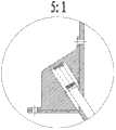
图3为本发明的局部放大图Fig. 3 is the local enlargement figure of the present invention
图中标号:Labels in the figure:
1-绞龙;2-进料器壳体;3-关风器;4-料仓;5-触头;6-连杆;7-齿轮变速箱;8-调频电机;9-底座;10-弹簧构件;11-直搅动杆;12-导轨;13-弯搅动杆。1-Auger; 2-Feeder shell; 3-Air shut-off device; 4-Main bin; 5-Contact; 6-Connecting rod; 7-Gear gearbox; 8-FM motor; 9-Base; 10 - spring member; 11 - straight stirring rod; 12 - guide rail; 13 - curved stirring rod.
具体实施方式Detailed ways
本发明提供了一种用于流化床生物质快速热解的螺旋进料器,下面通过附图和具体实施方式对本发明作进一步说明。The present invention provides a screw feeder for rapid pyrolysis of fluidized bed biomass, and the present invention will be further described below with reference to the accompanying drawings and specific embodiments.
如图1和图2所示,该生物质螺旋进料器的结构为:进料器壳体2、关风器3、料仓4通过法兰竖直连接,进料绞龙1位于进料器壳体2内,生物质经关风器3进入进料器壳体2内,再由绞龙1推入流化床反应器,保证了进料的连续、均匀。同时,关风器3的隔压锁风和进料器壳体2内物料的料封起到了防反喷的作用;位于料仓4内的搅动杆构件由直搅动杆11、弯搅动杆13、连杆6、触头5组成,一端通过螺栓与料仓壁连接,另一端连接弹簧构件10,直搅动杆11和弯搅动杆13由导轨12连接,搅动杆上焊接连杆6,连杆6两端为触头5;弯搅动杆13的下端与关风器3的叶片接触,通过关风器3的旋转运动为搅动杆构件提供动力,使搅动杆向上运动并挤压弹簧构件10。当弯搅动杆13的下端脱离关风器3的叶片时,弹簧构件10将搅动杆构件推向即将旋转过来的叶片,通过搅动杆构件的上下运动搅动物料,避免出现搭桥、挂壁等现象;调频电机8带动齿轮变速箱7为绞龙1和关风器3提供动力,同时保证二者的进料量一致;进料器壳体2与齿轮变速箱7通过螺栓固定在底座9上。As shown in Figure 1 and Figure 2, the structure of the biomass screw feeder is as follows: the feeder housing 2, the air lock 3, and the silo 4 are vertically connected by flanges, and the
Claims (4)
Translated fromChinesePriority Applications (1)
| Application Number | Priority Date | Filing Date | Title |
|---|---|---|---|
| CN201110422433.2ACN102492444B (en) | 2011-12-16 | 2011-12-16 | Spiral feeder used for fluidized-bed-type fast biomass pyrolysis |
Applications Claiming Priority (1)
| Application Number | Priority Date | Filing Date | Title |
|---|---|---|---|
| CN201110422433.2ACN102492444B (en) | 2011-12-16 | 2011-12-16 | Spiral feeder used for fluidized-bed-type fast biomass pyrolysis |
Publications (2)
| Publication Number | Publication Date |
|---|---|
| CN102492444Atrue CN102492444A (en) | 2012-06-13 |
| CN102492444B CN102492444B (en) | 2014-05-14 |
Family
ID=46184308
Family Applications (1)
| Application Number | Title | Priority Date | Filing Date |
|---|---|---|---|
| CN201110422433.2AExpired - Fee RelatedCN102492444B (en) | 2011-12-16 | 2011-12-16 | Spiral feeder used for fluidized-bed-type fast biomass pyrolysis |
Country Status (1)
| Country | Link |
|---|---|
| CN (1) | CN102492444B (en) |
Cited By (5)
| Publication number | Priority date | Publication date | Assignee | Title |
|---|---|---|---|---|
| CN103691366A (en)* | 2013-12-04 | 2014-04-02 | 厦门钨业股份有限公司 | Automatic sticky powder adding and feeding device for fluidized bed |
| CN104444435A (en)* | 2014-10-21 | 2015-03-25 | 汉中海涛机械有限责任公司 | Automatic rotating water distilling utensil erecting device |
| CN105368471A (en)* | 2015-12-11 | 2016-03-02 | 江苏鼎新环保科技有限公司 | Self-sealing biomass carbonization furnace feeding device |
| CN109530421A (en)* | 2018-11-20 | 2019-03-29 | 大连德联科技有限公司 | Vehicle-mounted integrated dry powder agent adding device |
| CN113913206A (en)* | 2021-08-24 | 2022-01-11 | 池州信安电子科技有限公司 | Carbon gasification pyrolysis furnace |
Citations (6)
| Publication number | Priority date | Publication date | Assignee | Title |
|---|---|---|---|---|
| US3183553A (en)* | 1961-11-10 | 1965-05-18 | Shell Oil Co | Crammer feeder for extruder |
| JP2000177793A (en)* | 1998-12-14 | 2000-06-27 | Itochu Seito Kk | Movable powder and granular substance conveyer |
| WO2009081475A1 (en)* | 2007-12-21 | 2009-07-02 | Kuma Engineering Co., Ltd. | Granule feeder |
| CN201553614U (en)* | 2009-11-27 | 2010-08-18 | 洛阳市冠奇工贸有限责任公司 | Automatic feeing system for producing spherical graphite |
| CN201932665U (en)* | 2010-08-17 | 2011-08-17 | 合肥德博生物能源科技有限公司 | Auger biomass feeding system with stirring device |
| CN202390371U (en)* | 2011-12-16 | 2012-08-22 | 北京林业大学 | Spiral feeder used for fluid-bed fast biomass pyrolysis |
- 2011
- 2011-12-16CNCN201110422433.2Apatent/CN102492444B/ennot_activeExpired - Fee Related
Patent Citations (6)
| Publication number | Priority date | Publication date | Assignee | Title |
|---|---|---|---|---|
| US3183553A (en)* | 1961-11-10 | 1965-05-18 | Shell Oil Co | Crammer feeder for extruder |
| JP2000177793A (en)* | 1998-12-14 | 2000-06-27 | Itochu Seito Kk | Movable powder and granular substance conveyer |
| WO2009081475A1 (en)* | 2007-12-21 | 2009-07-02 | Kuma Engineering Co., Ltd. | Granule feeder |
| CN201553614U (en)* | 2009-11-27 | 2010-08-18 | 洛阳市冠奇工贸有限责任公司 | Automatic feeing system for producing spherical graphite |
| CN201932665U (en)* | 2010-08-17 | 2011-08-17 | 合肥德博生物能源科技有限公司 | Auger biomass feeding system with stirring device |
| CN202390371U (en)* | 2011-12-16 | 2012-08-22 | 北京林业大学 | Spiral feeder used for fluid-bed fast biomass pyrolysis |
Cited By (7)
| Publication number | Priority date | Publication date | Assignee | Title |
|---|---|---|---|---|
| CN103691366A (en)* | 2013-12-04 | 2014-04-02 | 厦门钨业股份有限公司 | Automatic sticky powder adding and feeding device for fluidized bed |
| CN103691366B (en)* | 2013-12-04 | 2016-08-17 | 厦门钨业股份有限公司 | A kind of viscosity powder body auto feed for fluid bed, feed arrangement |
| CN104444435A (en)* | 2014-10-21 | 2015-03-25 | 汉中海涛机械有限责任公司 | Automatic rotating water distilling utensil erecting device |
| CN105368471A (en)* | 2015-12-11 | 2016-03-02 | 江苏鼎新环保科技有限公司 | Self-sealing biomass carbonization furnace feeding device |
| CN109530421A (en)* | 2018-11-20 | 2019-03-29 | 大连德联科技有限公司 | Vehicle-mounted integrated dry powder agent adding device |
| CN109530421B (en)* | 2018-11-20 | 2021-04-13 | 大连德联科技有限公司 | A vehicle-mounted integrated dry powder medicament adding device |
| CN113913206A (en)* | 2021-08-24 | 2022-01-11 | 池州信安电子科技有限公司 | Carbon gasification pyrolysis furnace |
Also Published As
| Publication number | Publication date |
|---|---|
| CN102492444B (en) | 2014-05-14 |
Similar Documents
| Publication | Publication Date | Title |
|---|---|---|
| CN102492444A (en) | Spiral feeder used for fluidized-bed-type fast biomass pyrolysis | |
| CN201128578Y (en) | Feeding device for viscous powdery material | |
| CN202429733U (en) | Gravity type biomass feeding device | |
| CN203200264U (en) | Efficient hybrid anaerobic fermentation device | |
| CN103374521B (en) | Mechanical and hydraulic combined stirring straw anaerobic fermentation biogas preparation engineering device | |
| CN201309931Y (en) | Horizontal anaerobic reactor for producing methane based on solid fermentation of organic waste | |
| CN102910387A (en) | Raw coal bunker loosening and dredging device | |
| CN204138350U (en) | The horizontal physically activated reactor of accurate control | |
| CN202389818U (en) | Biomass storage silo device with continuous feeding function | |
| CN201932665U (en) | Auger biomass feeding system with stirring device | |
| CN108315237B (en) | Gravity plug-flow dry fermentation gas fertilizer co-production device and method thereof | |
| CN202864127U (en) | Raw coal bunker loosening and dredging device | |
| CN202390371U (en) | Spiral feeder used for fluid-bed fast biomass pyrolysis | |
| CN204656368U (en) | A kind of screw mixer | |
| CN202244834U (en) | Storage bin | |
| CN110304359A (en) | A rotary scraper cleaning machine | |
| CN206604427U (en) | New bio alcohol-based fuel preparation facilities | |
| CN203990348U (en) | A kind of unpowered three-dimensional pan feeding liquid-solid medium mixing arrangement | |
| CN206853572U (en) | A kind of blend tank double-stirring machine | |
| CN204656464U (en) | A kind of water Jiao slurry preparation facilities with modified function | |
| CN205855445U (en) | A kind of easy caking materials conveyer device | |
| CN201524535U (en) | Cone shaped stirrer | |
| CN208711511U (en) | A kind of bulk blended fertilizer positive mixer structure | |
| CN201728074U (en) | Polyurethane resin stirring synthesizer | |
| CN207712713U (en) | A kind of vacuum feeding tank |
Legal Events
| Date | Code | Title | Description |
|---|---|---|---|
| C06 | Publication | ||
| PB01 | Publication | ||
| C10 | Entry into substantive examination | ||
| SE01 | Entry into force of request for substantive examination | ||
| C53 | Correction of patent of invention or patent application | ||
| CB03 | Change of inventor or designer information | Inventor after:Si Hui Inventor after:Li Long Inventor after:Guo Xiaohui Inventor after:Che Yanzhe Inventor after:Chang Jianmin Inventor after:Ren Xueyong Inventor before:Li Long Inventor before:Si Hui Inventor before:Guo Xiaohui Inventor before:Che Yanzhe Inventor before:Chang Jianmin Inventor before:Ren Xueyong | |
| COR | Change of bibliographic data | Free format text:CORRECT: INVENTOR; FROM: LI LONG SI HUI GUO XIAOHUI CHE YANZHE CHANG JIANMIN REN XUEYONG TO: SI HUI LI LONG GUO XIAOHUI CHE YANZHE CHANG JIANMIN REN XUEYONG | |
| C14 | Grant of patent or utility model | ||
| GR01 | Patent grant | ||
| CF01 | Termination of patent right due to non-payment of annual fee | ||
| CF01 | Termination of patent right due to non-payment of annual fee | Granted publication date:20140514 |