CN102486389A - A Grain Depot Temperature and Humidity Measuring Device Based on Wireless Sensor Network - Google Patents
A Grain Depot Temperature and Humidity Measuring Device Based on Wireless Sensor NetworkDownload PDFInfo
- Publication number
- CN102486389A CN102486389ACN2010105729147ACN201010572914ACN102486389ACN 102486389 ACN102486389 ACN 102486389ACN 2010105729147 ACN2010105729147 ACN 2010105729147ACN 201010572914 ACN201010572914 ACN 201010572914ACN 102486389 ACN102486389 ACN 102486389A
- Authority
- CN
- China
- Prior art keywords
- microprocessor
- circuit
- interface
- data
- temperature
- Prior art date
- Legal status (The legal status is an assumption and is not a legal conclusion. Google has not performed a legal analysis and makes no representation as to the accuracy of the status listed.)
- Pending
Links
Images


Landscapes
- Arrangements For Transmission Of Measured Signals (AREA)
Abstract
Description
Translated fromChinese技术领域technical field
本专利涉及的是粮库测温、湿装置,具体来说是基于单片机和无线射频技术设计了一种无线化、智能化、网络化、低功耗的粮库无线测温、湿装置。This patent relates to a grain depot temperature and humidity measuring device, specifically, a wireless, intelligent, networked, low-power grain depot wireless temperature and humidity measuring device is designed based on single-chip microcomputer and radio frequency technology.
背景技术Background technique
粮食仓储库是粮食仓储的基本单元,库区面积大且分散。为了保证粮食在储藏过程中的安全,粮库粮情监测系统是必不可少的。随着电子技术、计算机应用技术、通讯技术和网络技术的进步和发展,高新技术已被应用于粮库监测系统,粮库监测技术是科学保粮的关键技术之一。多年来,在粮食部门和科技人员的大力协作下,粮情监测技术不断得到完善、提高、并且趋向成熟,逐步形成了样式繁多的粮情监测系统,为安全、科学储备粮食起到了积极的作用。Grain storage warehouse is the basic unit of grain storage, and the storage area is large and scattered. In order to ensure the safety of grain during storage, a grain monitoring system for grain depots is essential. With the progress and development of electronic technology, computer application technology, communication technology and network technology, high technology has been applied to the grain depot monitoring system, and the grain depot monitoring technology is one of the key technologies for scientific grain preservation. Over the years, under the vigorous cooperation of the grain department and scientific and technological personnel, the grain monitoring technology has been continuously improved, improved, and matured, and gradually formed a variety of grain monitoring systems, which played a positive role in the safe and scientific storage of grain. .
目前,国内粮库特别是中小型粮库在仓储管理中由于技术和资金上的原因,多数仅限于只对温、湿度进行人工现场监测,依靠人工进行测量,效率低,准确性差,当温度超标时不能及时发现险情并进行相应处理,从而造成大量损失。因此,研究开发面向中小粮库的粮情监测与管理系统已是迫在眉睫,在该粮库无线测温、湿装置的基础上实现的中小粮库粮情监测与管理系统可以很好地解决中小粮库当前所面临的问题。At present, due to technical and financial reasons in storage management of domestic grain depots, especially small and medium-sized grain depots, most of them are limited to manual on-site monitoring of temperature and humidity, relying on manual measurement, which has low efficiency and poor accuracy. The dangerous situation cannot be detected in time and dealt with accordingly, resulting in a large amount of losses. Therefore, it is imminent to research and develop a grain situation monitoring and management system for small and medium-sized grain depots. The grain situation monitoring and management system for small and medium-sized grain depots based on the wireless temperature and humidity measurement devices of this grain depot can solve the problem of small and medium-sized grain depots. Problems the library is currently facing.
传统上我国大部分粮库采用的是有线测温、湿,各部件之间采用电缆进行数据传送,这种测温、湿设备线路多,布线复杂、维护困难。易受用于粮食熏蒸的磷化氢气体的腐蚀,造成大量的测温器件瘫痪,因此增加了粮食的存储成本。而许多粮食仓储单位采用的测温仪器与人工抄录、管理相结合的传统方法不仅效率低,而且往往由于判断失误和管理不力造成局部或大范围的粮食霉变现象时有发生。Traditionally, most grain depots in my country use wired temperature and humidity measurement, and cables are used to transmit data between components. This kind of temperature measurement and humidity equipment has many lines, complicated wiring, and difficult maintenance. It is easily corroded by phosphine gas used for grain fumigation, causing a large number of temperature measuring devices to be paralyzed, thus increasing the storage cost of grain. However, the traditional method of combining temperature measuring instruments with manual transcription and management adopted by many grain storage units is not only inefficient, but also often causes partial or large-scale grain mildew due to misjudgment and poor management.
无线传感器节点构成的一种具有动态路由节点随意放置移植性好,系统可重构性强,成本低,单一节点损坏不影响整个网络传输采集,精确监控和灵活方便的特点的对粮库进行温度、湿度监控的无线传感器网络。彻底摆脱了传统的人工抄录方法,构建粮情数据分析决策上位机系统实时检测粮仓中的温、湿度,确保粮仓内合适的温、湿度环境。A system composed of wireless sensor nodes has the characteristics of dynamic routing nodes, good portability, strong system reconfigurability, low cost, single node damage does not affect the entire network transmission and collection, accurate monitoring and flexible and convenient temperature monitoring of grain depots. , Wireless sensor network for humidity monitoring. Completely get rid of the traditional manual transcription method, and build a host computer system for grain data analysis and decision-making to detect the temperature and humidity in the granary in real time to ensure a suitable temperature and humidity environment in the granary.
随着科学技术的快速发展,粮库测温、湿装置的发展趋势必然是向无线化、智能化和网络化方向发展,人工测粮库温、湿度方法及其传统的管理方式必将遭到摒弃。With the rapid development of science and technology, the development trend of temperature and humidity measurement devices in grain depots is bound to be wireless, intelligent and networked. abandon.
发明内容Contents of the invention
本发明的目的是针对目前中小型粮库人工现场监测存在诸多不适的问题,而提供极为适用于中小型粮库,可实现自动测温、湿和上位机数据显示和管理的一种基于无线网络的粮库无线测温、湿系统。The purpose of the present invention is to provide a wireless network-based system that is extremely suitable for small and medium-sized grain depots and can realize automatic temperature measurement, humidity, and upper computer data display and management in view of the many discomforts in the manual on-site monitoring of small and medium-sized grain depots. wireless temperature and humidity measurement system for grain depots.
解决上述问题所采取的技术方案是:The technical solution adopted to solve the above problems is:
一种基于无线网络的粮库无线测温、湿系统,包括:无线传感器节点系统、集中器系统,其中集中器系统与上位机相连。如图1所示,所述无线传感器节点系统采集温、湿度信息后通过射频电路向集中器系统发送,集中器系统经由射频电路接收到信息后,可在其外围存储器上进行存储;集中器系统与上位机通过RS232串行通信方式传输,温、湿度信息传送到上位机以后,可以由软件实现存储、数据处理、显示、报警等一系列功能。A wireless temperature and humidity measurement system for a grain depot based on a wireless network includes: a wireless sensor node system and a concentrator system, wherein the concentrator system is connected to a host computer. As shown in Figure 1, after the wireless sensor node system collects temperature and humidity information, it sends it to the concentrator system through the radio frequency circuit, and after the concentrator system receives the information through the radio frequency circuit, it can store it on its peripheral memory; the concentrator system It is transmitted with the upper computer through RS232 serial communication. After the temperature and humidity information is transmitted to the upper computer, a series of functions such as storage, data processing, display, and alarm can be realized by software.
上述无线传感器节点系统如图2所示,包括低功耗数字传感器SHT11、无线传感器节点微处理器MSP430、射频电路CC1100、调试接口(JTAG)、存储器AT45DB041、电源系统等。其中处理器MSP430与其余各外围电路相连;电源系统与各部分电路相连,本系统采用2节5号碱性电池作为电源,电源系统由供电单元以及动态电源管理单元组成,动态电源管理单元设有节点电压监测电路。传感器SHT11通过数据线和时钟线与微处理器MSP430相连,JTAG通过信号线与微处理器MSP430相连,存储器AT45DB041的各接口与微处理器MSP430的通用I/O口相连,射频电路CC1100的各接口通过4线SPI总线与微处理器MSP430通用I/O口相连,电源系统分别与各器件VCC接口相连进行供电并设有电压监测电路。The above wireless sensor node system is shown in Figure 2, including low power consumption digital sensor SHT11, wireless sensor node microprocessor MSP430, radio frequency circuit CC1100, debugging interface (JTAG), memory AT45DB041, power supply system, etc. Among them, the processor MSP430 is connected with other peripheral circuits; the power supply system is connected with each part of the circuit. This system uses 2 AA alkaline batteries as the power supply. The power supply system is composed of a power supply unit and a dynamic power management unit. The dynamic power management unit is equipped with Node voltage monitoring circuit. The sensor SHT11 is connected with the microprocessor MSP430 through the data line and the clock line, JTAG is connected with the microprocessor MSP430 through the signal line, each interface of the memory AT45DB041 is connected with the general I/O port of the microprocessor MSP430, each interface of the radio frequency circuit CC1100 The 4-wire SPI bus is connected to the general-purpose I/O port of the microprocessor MSP430, and the power supply system is connected to the VCC interface of each device for power supply and has a voltage monitoring circuit.
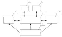
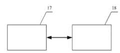
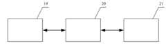
上述集中器系统如图3所示,包括射频电路CC1100、微处理器STC89LE58RD+、复位电路、按键电路、液晶显示电路、存储电路、串行通信电路等几部分。其中处理器STC89LE58RD+与其余各外围电路相连;射频电路CC1100通过4线SPI总线与微处理器STC89LE58RD+的通用I/O口相连,复位芯片MAX810R与微处理器STC89LE58RD+的复位接口相连,按键电路分别与与微处理器STC89LE58RD+的中断接口、通用接口、计时器接口相连,液晶显示电路OCMJ4X8C直接与微处理器STC89LE58RD+相连,存储电路与STC89LE58RD+的通用接口相连,串行通信电路与STC89LE58RD+的串行输入、输出端RXD、TXD相连。上述存储电路如图4所示,包括锁存器74HC573和集中器的存储器HK1255-7,锁存器74HC573的控制位接口与STC89LE58RD+的通用I/O口相连,存储器HK1255-7与锁存器74HC573的对应接口相连;上述串行通信电路如图5所示,RS232与STC89LE58RD+的串行输入、输出端RXD、TXD相连,RS232通过串口线同时与上位机的串行输入、输出端PC RXD、PC TXD相连。The above-mentioned concentrator system is shown in Figure 3, including radio frequency circuit CC1100, microprocessor STC89LE58RD+, reset circuit, key circuit, liquid crystal display circuit, storage circuit, serial communication circuit and other parts. Among them, the processor STC89LE58RD+ is connected with other peripheral circuits; the radio frequency circuit CC1100 is connected with the general I/O port of the microprocessor STC89LE58RD+ through the 4-wire SPI bus, the reset chip MAX810R is connected with the reset interface of the microprocessor STC89LE58RD+, and the key circuit is connected with the The interrupt interface, general interface and timer interface of microprocessor STC89LE58RD+ are connected, the liquid crystal display circuit OCMJ4X8C is directly connected with microprocessor STC89LE58RD+, the storage circuit is connected with the general interface of STC89LE58RD+, and the serial communication circuit is connected with the serial input and output terminals of STC89LE58RD+ RXD and TXD are connected. The above storage circuit is shown in Figure 4, including the latch 74HC573 and concentrator memory HK1255-7, the control bit interface of the latch 74HC573 is connected to the general I/O port of STC89LE58RD+, the memory HK1255-7 is connected to the latch 74HC573 The above serial communication circuit is shown in Figure 5, RS232 is connected to the serial input and output terminals RXD and TXD of STC89LE58RD+, and RS232 is connected to the serial input and output terminals PC RXD and PC of the upper computer through the serial port line at the same time. TXD is connected.
本发明的工作原理及操作程序:Working principle and operating procedure of the present invention :
本监测系统利用无线传感器网络技术构成了一个集粮情监测、监测温湿度分析和粮温报警控制为一体的粮情监测系统。系统组成框图如图1所示。整个系统由一台上位机、一台集中器(Sink)和大量功能强大的传感器测温节点等组成。上位机(PC机)和集中器放在粮库的粮情监测中心,它们距离很近,用RS232连接。集中器通过无线通信方式与各个粮仓的测温节点连接传输数据。This monitoring system uses wireless sensor network technology to form a grain monitoring system that integrates grain monitoring, monitoring temperature and humidity analysis, and grain temperature alarm control. The block diagram of the system is shown in Figure 1. The whole system consists of a host computer, a concentrator (Sink) and a large number of powerful sensor temperature measurement nodes. The upper computer (PC) and the concentrator are placed in the grain situation monitoring center of the grain depot, they are very close and connected by RS232. The concentrator is connected to the temperature measurement nodes of each granary through wireless communication to transmit data.
根据粮库的测温结构与无线传感器网络的分簇结构的相似,粮库的多个粮仓紧密排列在一起,每个粮仓内有多个测温节点,所以这里我们采用分簇结构对粮库的进行粮情监测。分簇路由技术是当前无线网络传感器技术的前沿技术,通过增加无线通讯模块来实施的。本发明中的无线传感器节点可以分为簇头节点和簇内节点,在分簇结构中将每个粮仓划分成一个簇,每个簇由一个簇头节点和多个簇内测温节点组成。每个仓的簇内节点通过单跳路由机制把数据传送给簇头节点;每个仓的簇头形成了高一级的网络,在簇头之间传输数据,通过多跳转发给集中器,在由集中器上传给PC机,以实现粮情监测。簇内成员节点负责采集数据,然后将采集到的数据传送给它所属的簇的簇头,由簇头节点对簇内成员传送过来的数据进行处理,然后簇头把处理后的数据通过簇头网络传送给粮情监测中心或远程监测中心。 According to the similarity between the temperature measurement structure of the grain depot and the clustering structure of the wireless sensor network, multiple granaries of the grain depot are closely arranged together, and there are multiple temperature measurement nodes in each granary, so here we use the clustering structure to monitor the grain depot for food monitoring. The cluster routing technology is the frontier technology of the current wireless network sensor technology, which is implemented by adding wireless communication modules. The wireless sensor nodes in the present invention can be divided into cluster head nodes and intra-cluster nodes. In the cluster structure, each granary is divided into a cluster, and each cluster is composed of a cluster head node and multiple temperature measurement nodes in the cluster. The intra-cluster nodes of each bin transmit data to the cluster head node through a single-hop routing mechanism; the cluster head of each bin forms a higher-level network, transmits data between cluster heads, and forwards data to the concentrator through multi-hop , and uploaded by the concentrator to the PC to realize grain situation monitoring. The member nodes in the cluster are responsible for collecting data, and then transmit the collected data to the cluster head of the cluster to which it belongs. The cluster head node processes the data transmitted by the members in the cluster, and then the cluster head passes the processed data through the cluster head Network transmission to grain monitoring center or remote monitoring center. the
本专利的无线传感器节点示意图如图2所示,其中簇头节点和簇内节点均具有相同的构造,均是由温湿度传感器、微处理器、射频电路、调试和下载接口、存储器、电源系统等组成。The schematic diagram of the wireless sensor node of this patent is shown in Figure 2, wherein the cluster head node and the nodes in the cluster all have the same structure, and are composed of a temperature and humidity sensor, a microprocessor, a radio frequency circuit, a debugging and download interface, a memory, and a power supply system and so on.
处理器单元是传感器网络节点的核心,和其他单元一起完成数据的采集、处理和收发。由于节点采用电池供电,因此功耗问题显得至关重要,无线传感器节点就是采用MSP430系列的微控制器,功耗非常低,综合比较几种单片机,本专利选用了TI公司的MSP430F169单片机。The processor unit is the core of the sensor network node, and completes data collection, processing and sending and receiving together with other units. Because the nodes are powered by batteries, the power consumption problem is very important. The wireless sensor nodes use MSP430 series microcontrollers, which have very low power consumption. Comparing several single-chip microcomputers comprehensively, this patent selects TI's MSP430F169 single-chip microcomputer.
温湿度传感器SHT11能支持低功耗模式,温湿度传感器和微处理器通信采用串行二线接口SCK和DATA,其中SCK为时钟线,DATA为数据线,用以传输微处理器的命令,使传感器采集数据并上传。湿度值输出分辨率为14位,温度值输出分辨率为12位,并可编程为12位和8位。为了更精确的测量仓内的测温节点的温度和湿度值,SHT11可以通过温湿度的线性补偿测量到更精准的监测数据,采集完数据后自动转入休眠模式。The temperature and humidity sensor SHT11 can support low power consumption mode. The communication between the temperature and humidity sensor and the microprocessor adopts the serial two-wire interface SCK and DATA, where SCK is the clock line and DATA is the data line, which is used to transmit the commands of the microprocessor and make the sensor Collect data and upload it. Humidity value output resolution is 14 bits, temperature value output resolution is 12 bits, and can be programmed as 12 bits and 8 bits. In order to more accurately measure the temperature and humidity values of the temperature measurement nodes in the warehouse, SHT11 can measure more accurate monitoring data through linear compensation of temperature and humidity, and automatically switch to sleep mode after collecting data.
无线射频芯片CC1100是Chipcon公司推出的一款低成本单片的UHF收发器,专为低功耗无线应用而设计,CC1100的工作特点是自动产生前导码和CRC可以很容易通过SPI接口进行编程配置,电流消耗低。CC1100共有20个引脚,其中有6个引脚和单片机的I/O口相连。CC1100通过4线SPI总线接口(SI、SO、SCLK和CSn)实现MSP430F169单片机通信。SPI接口上所有操作都包含一个读/写位,一个突发访问位和一个6位地址的头字节。其中,SCLK脚是串行时钟接口;SO脚是串行输出接口;CSN脚是串行配置选择引脚;SI脚是串行输入接口。它工作在SPI的从模式,该模式同时用作写缓存数据。The wireless radio frequency chip CC1100 is a low-cost single-chip UHF transceiver launched by Chipcon. It is specially designed for low-power wireless applications. The working feature of CC1100 is that it automatically generates preambles and CRCs and can be easily programmed and configured through the SPI interface. , low current consumption. CC1100 has a total of 20 pins, 6 of which are connected to the I/O port of the microcontroller. CC1100 realizes MSP430F169 microcontroller communication through 4-wire SPI bus interface (SI, SO, SCLK and CSn). All operations on the SPI interface consist of a read/write bit, a burst access bit and a 6-bit address header byte. Among them, the SCLK pin is a serial clock interface; the SO pin is a serial output interface; the CSN pin is a serial configuration selection pin; the SI pin is a serial input interface. It works in SPI slave mode, which is also used as write buffer data.
节点的存储芯片AT45DB041是ATMEL公司的新型512KB的串行FLASH芯片,外部电路简单,体积小,功耗低,适合传感器节点设计。AT45DB041B在进行编写和读操作时,片选引脚CS和一个连续输入SI,连续输出SO和连续时钟SCK组成的三线访问接口使得AT45DB041正常工作。 所有的编写周期都是自同步的,因而在编写之前都无需分开的擦除周期。AT45DB041外围电路非常简单,可以很方便地与微控制器连接。SO、SI、SCK、/CS、/WP分别与微处理器的通用I/O相连即可。The memory chip AT45DB041 of the node is a new 512KB serial FLASH chip of ATMEL Company, the external circuit is simple, the volume is small, the power consumption is low, it is suitable for the design of the sensor node. When AT45DB041B is writing and reading, the three-wire access interface composed of chip select pin CS and a continuous input SI, continuous output SO and continuous clock SCK makes AT45DB041 work normally. All program cycles are self-synchronized, so there is no need for a separate erase cycle prior to programming. The peripheral circuit of AT45DB041 is very simple and can be easily connected with the microcontroller. SO, SI, SCK, /CS, /WP can be connected with the general-purpose I/O of the microprocessor respectively.
JTAG(Joint Test Action Group联合测试行动小组) 是一种国际标准测试协议,主要用于芯片内部测试及对系统进行仿真、调试, JTAG的基本原理是在器件内部定义一个TAP(Test Access Port)测试访问口)通过专用的JTAG测试工具对进行内部节点进行测试。JTAG口的芯片都有如下JTAG引脚定义: JTAG (Joint Test Action Group Joint Test Action Group) is an international standard test protocol, mainly used for chip internal testing and system simulation and debugging. The basic principle of JTAG is to define a TAP (Test Access Port) test inside the device access port) to test the internal nodes through a dedicated JTAG test tool. The chip with JTAG port has the following JTAG pin definitions:
TCK——测试时钟输入; TCK——Test clock input;
TDI——测试数据输入,数据通过TDI输入JTAG口; TDI——Test data input, the data is input to the JTAG port through TDI;
TDO——测试数据输出,数据通过TDO从JTAG口输出; TDO——Test data output, the data is output from the JTAG port through TDO;
TMS——测试模式选择,TMS用来设置JTAG口处于某种特定的测试模式。TMS——Test mode selection, TMS is used to set the JTAG port in a specific test mode.
可选引脚TRST——测试复位,输入引脚,低电平有效。Optional pin TRST - test reset, input pin, active low.
电能是传感器网络珍贵的资源,节点电能一旦耗尽,即宣布其寿命到期并将退出网络。无论是微处理器系统、外围电路、CC1100无线模块等所用器件的工作电压都工作在3V,所以本系统采用2节5号碱性电池作为电源。并且随着整个系统的运行,电池电压会随之缓慢地下降,所以需要当电源电压下降到系统工作的临界值时,CPU能及时检测到并及时作出反应。这就需要传感器节点有一个比较有效的电池电量监测单元,本专利中采用加州大学伯克利分校研制的Mica2节点的电压监测电路来监测电源的供应情况。单片机系统、CC1100无线模块等器件的工作电压最低可以达到2.4V,但是不能过低,鉴于这个原因,则应选用警戒值为2.6V的电压监测芯片。Electric energy is a precious resource in sensor networks. Once the energy of a node is exhausted, it will declare its life expired and exit the network. No matter the operating voltage of the microprocessor system, peripheral circuit, CC1100 wireless module and other devices used is 3V, so this system uses 2 AAA alkaline batteries as the power supply. And with the operation of the whole system, the battery voltage will drop slowly, so it is necessary for the CPU to detect and respond in time when the power supply voltage drops to the critical value of the system. This requires the sensor node to have a relatively effective battery power monitoring unit. In this patent, the voltage monitoring circuit of the Mica2 node developed by the University of California, Berkeley is used to monitor the power supply situation. The working voltage of devices such as single-chip microcomputer system and CC1100 wireless module can reach 2.4V at least, but it cannot be too low. For this reason, a voltage monitoring chip with a warning value of 2.6V should be selected.
本专利的集中器系统示意图如图3所示,集中器负责接受簇头上传的监测数据并将监测数据存储起来,然后再将监测数据通过串口传给上位机。包括射频电路CC1100、微处理器STC89LE58RD+、复位电路、按键电路、液晶显示电路、存储电路、串行通信电路等几部分。The schematic diagram of the concentrator system of this patent is shown in Figure 3. The concentrator is responsible for receiving the monitoring data uploaded by the cluster head and storing the monitoring data, and then transmitting the monitoring data to the host computer through the serial port. Including radio frequency circuit CC1100, microprocessor STC89LE58RD+, reset circuit, button circuit, liquid crystal display circuit, storage circuit, serial communication circuit and other parts.
由于集中器的不要求低功耗,且为了保证数据的安全性,我们采用加密性高、超强抗干扰能力强的STC89LE58RD+单片机作为集中器的微处理器。STC89LE58RD+单片机的最高时钟频率0~80MHz,可选的“6 时钟/机器周期”和“12时钟/ 机器周期”倍频功能,让它具备很高的处理速度。它有32K的Flash存储器、16K字节的 
集中器的射频电路CC1100在传感器节点构造处已经介绍过,不再赘述,唯一的区别在于功能的不同:上述传感器节点中簇内节点中射频电路只负责发送信息给簇头结点,簇头结点既负责接收信息又负责发送信息;而集中器的射频电路只负责接收信息。The radio frequency circuit CC1100 of the concentrator has been introduced in the structure of the sensor node, and will not be repeated. The only difference lies in the difference in function: the radio frequency circuit in the node in the cluster of the above sensor nodes is only responsible for sending information to the cluster head node, and the cluster head node The point is responsible for both receiving information and sending information; while the radio frequency circuit of the concentrator is only responsible for receiving information.
复位电路复位芯片采用MAX810R,MAX810R是一种单一功能的微处理器复位芯片,用于监控微控制器和其他逻辑系统的电源电压。它可以在上电,掉电和节电情况下向微控制器提供复位信号。当电源电压低于预设的门槛电压时,器件会发出复位信号,直到在一段时间内电源电压又恢复到高于门槛电压为止。Reset circuit The reset chip adopts MAX810R, which is a single-function microprocessor reset chip, which is used to monitor the power supply voltage of microcontrollers and other logic systems. It can provide a reset signal to the microcontroller during power-up, power-down and power-down situations. When the supply voltage falls below a preset threshold voltage, the device issues a reset signal until the supply voltage returns above the threshold voltage for a period of time.
按键电路直接与集中器的微处理器STC89LE58RD+相连,按键按下则提供低电平信号,其主要功能是实现中断、程序检测、LCD数据显示调用程序,选择菜单子程序等功能。The button circuit is directly connected to the microprocessor STC89LE58RD+ of the concentrator. When the button is pressed, a low-level signal is provided. Its main function is to realize interrupt, program detection, LCD data display, call program, and select menu subroutine.
液晶显示电路采用OCMJ4X8C这款液晶直接与微处理器相连,可以接受串行或者并行的数据。内置2M位中文字型ROM (CGROM)总共提供8192个中文字型。为了节省引脚,所以本设计采用串行方式传输数据,其中二极管
集中器是监测数据最终下位机存储设备,而监测数据的安全存储和快速存储直接影响了整个粮情监测系统的正常运行。为了保证监测数据能够快速、安全的存储,又因为存储器的写循环次数不受限制,所以我们采用这种非易失性存储器HK1255-7作为集中器的存储器。HK1255-7有一个自带锂电源和控制电路,经常监视Vcc是否超过容许条件。当超过容许条件时,锂电源自动接通,写保护无条件启动以保护混淆数据。此外,HK1255-7 能够无条件地写存储器的保护块,所以无意中做的写操作不会干扰程序和特殊的数据空间。74HC573是用来锁存HK1255存储器的地址和数据的锁存器。当单片机为读状态时,通过控制位CS573A、CS573B、CS573C的置位将送出来的地址锁存到HK1255的地址位上,当HK1255的/CSSRAM和/RD置位时,读HK1255输出的此地址的数据。微处理器的数据和地址或者向微处理器输入HK1255数据和地址。当单片机为写状态时,通过控制位CS573A、CS573B、CS573C的置位将送出来的地址锁存到HK1255的地址位上,当HK1255的/CSSRAM和/WE置位时,读单片机输出的数据,HK1255将数据保存在此地址中。这里D0-D7是数据位,A0-A18是HK1255的地址位,/RD是读状态位,/WE是写状态位。The concentrator is the final lower computer storage device for monitoring data, and the safe and fast storage of monitoring data directly affects the normal operation of the entire grain monitoring system. In order to ensure that the monitoring data can be stored quickly and safely, and because the number of write cycles of the memory is not limited, we use this non-volatile memory HK1255-7 as the memory of the concentrator. HK1255-7 has a built-in lithium power supply and control circuit, which constantly monitors whether Vcc exceeds the allowable condition. When the allowable condition is exceeded, the lithium power supply is automatically turned on, and the write protection is activated unconditionally to protect confusing data. In addition, the HK1255-7 is able to unconditionally write to protected blocks of memory, so unintentional write operations will not interfere with programs and special data spaces. 74HC573 is a latch used to latch the address and data of HK1255 memory. When the microcontroller is in the read state, the address sent out is latched to the address bit of HK1255 by setting the control bits CS573A, CS573B, and CS573C. When the /CSSRAM and /RD of HK1255 are set, read the address output by HK1255 The data. Data and address of the microprocessor or input HK1255 data and address to the microprocessor. When the single-chip microcomputer is in the writing state, the sent address is latched to the address bit of HK1255 by setting the control bits CS573A, CS573B, and CS573C. When the /CSSRAM and /WE of HK1255 are set, the data output by the single-chip microcomputer is read. HK1255 saves data in this address. Here D0-D7 is the data bit, A0-A18 is the address bit of HK1255, /RD is the read status bit, /WE is the write status bit.
串行通信电路采用RS232传输方式,利用集中器的串口将采集到的监测数据上传给上位机,上位机也通过串口下发命令给集中器。在传输帧中我们定义了传输控制命令,采用应答机制保证准确可靠的传输数据。PC_TXD和PC_TXD是与PC机连接的发送端和接受端, TXD和TXD是与集中器连接的串口的发送端和接受端。The serial communication circuit adopts the RS232 transmission mode, and uses the serial port of the concentrator to upload the collected monitoring data to the host computer, and the host computer also sends commands to the concentrator through the serial port. In the transmission frame, we define the transmission control command, and use the response mechanism to ensure accurate and reliable transmission of data. PC_TXD and PC_TXD are the sender and receiver connected to the PC, TXD and TXD are the sender and receiver of the serial port connected to the concentrator.
操作步骤:Steps:
1、在本系统的硬件按要求连接成功后,就需启动软件才能正常工作并发挥它的功能;在系统进行上电以后,系统自动由主程序的初始化开始,进入程序主循环。1. After the hardware of this system is successfully connected as required, the software needs to be started to work normally and perform its functions; after the system is powered on, the system automatically starts from the initialization of the main program and enters the main loop of the program.
无线传感器节点来说,仓内测温节点的软件采用模块化的设计方法。软件由主程序和中断服务子程序组成。主程序包括初始化程序和监控程序;中断服务子程序包括中断处理子程序、无线数据收发子程序、数据采集子程序、簇协议子程序、低功耗子程序等。由于系统软件采用模块化设计,因而主程序只负责调用各功能模块程序。在系统进行上电以后,主程序由系统的初始化开始,进入程序主循环,依次判定是否加入网络、电池是否欠压、是否收到无线数据、是否发给本地址、等操作,待这些判断结束后再进行数据的定时采集与发送,最后进入睡眠低功耗模式,等待中断“唤醒”单片机。For wireless sensor nodes, the software of temperature measurement nodes in the warehouse adopts a modular design method. The software is composed of main program and interrupt service subroutine. The main program includes an initialization program and a monitoring program; the interrupt service subroutine includes an interrupt processing subroutine, a wireless data sending and receiving subroutine, a data acquisition subroutine, a cluster protocol subroutine, a low power consumption subroutine, and the like. Because the system software adopts modular design, the main program is only responsible for calling the program of each functional module. After the system is powered on, the main program starts from the initialization of the system, enters the main loop of the program, and successively determines whether to join the network, whether the battery is under voltage, whether to receive wireless data, whether to send to this address, etc., and wait for these judgments to end After that, the data is collected and sent regularly, and finally enters the sleep low power consumption mode, waiting for an interrupt to "wake up" the microcontroller.
对于集中起来说,在主体程序执行前,必须对初始状态进行设计,否则程序主体将不能正常执行,也得不到正确的结果。本系统程序的初始化包括以下方面的内容: CPU寄存器、状态和控制寄存器的定义; 所使用的存储单元的初始化,包括RAM数据初始化和非易失性随机访问存储器(HK1255-7)数据初始化; CC1100各个控制寄存器的初始化配置等; 端口控制寄存器的设置,如I/O口初始化、液晶控制口初始化等。需要指出的是并非所有单片机的控制/方式寄存器和工作寄存器都需要进行初始化,一般只需对参与工作的寄存器进行初始化。由于粮情监测系统软件采用模块化设计,因而测温节点主程序只负责调用各功能模块程序。主程序由系统的初始化开始,进入程序主循环,依次判定是否是本机地址、是否收到簇头节点的数据、数据是否接受正确、是否存在中断、按键是否按下等操作,待这些判断结束后再进行液晶显示,等待中断处理结束。For concentration, before the execution of the main program, the initial state must be designed, otherwise the main body of the program will not be executed normally, and the correct result will not be obtained. The initialization of this system program includes the following aspects: Definition of CPU registers, status and control registers; Initialization of storage units used, including RAM data initialization and non-volatile random access memory (HK1255-7) data initialization; CC1100 Initial configuration of each control register, etc.; Port control register settings, such as I/O port initialization, LCD control port initialization, etc. It should be pointed out that not all control/mode registers and working registers of the single-chip microcomputer need to be initialized, and generally only the registers involved in the work need to be initialized. Since the software of the grain situation monitoring system adopts a modular design, the main program of the temperature measurement node is only responsible for calling the programs of each functional module. The main program starts from the initialization of the system, enters the main loop of the program, and judges in turn whether it is the local address, whether the data from the cluster head node is received, whether the data is received correctly, whether there is an interruption, whether the button is pressed, etc., and wait for these judgments to end Then display the liquid crystal display and wait for the end of the interrupt processing.
2、在系统上电进行初始化和自检完成后,便可以进行测量数据和数据传输了。主机发出启动SHT11命令,经过数据传输的初始化,主机再发送测温命令,SHT11便开始测量数据。当CC1100处于睡眠模式时,天线实时监测无线网络中的前导信号,一旦确认同步信号,则意味着本机已经和发送数据的节点取得同步,接着就唤醒CC1100开始接收有效数据。接着开始判断地址字节,如果地址字节为本机地址,则判断是否是什么样的命令,一旦确认,MCU就开始利用路由算法进行路径的分析,向控制中心发送应答信号,将数据打包之后就通过天线向无线网络发送数据。整个操作结束后CC1100继续睡眠。需要指出的是,CC1100处于睡眠模式并不是所有的功能都关闭,因为WOR必须被设置为开启状态,电磁波激活(WOR)功能使CC1100能够周期地从深度休眠状态激活,不需要MCU的作用也能侦测到来的数据包,这样才能保证实时监测空中的信息帧,来确保整个网络的有效运行。2. After the system is powered on for initialization and self-inspection, the measurement data and data transmission can be performed. The host sends out the command to start SHT11, after the initialization of data transmission, the host then sends a temperature measurement command, and SHT11 starts to measure data. When CC1100 is in sleep mode, the antenna monitors the leading signal in the wireless network in real time. Once the synchronization signal is confirmed, it means that the machine has synchronized with the node sending data, and then wakes up CC1100 to start receiving valid data. Then start to judge the address byte. If the address byte is the local address, then judge whether it is a command. Once confirmed, the MCU will start to use the routing algorithm to analyze the path, send a response signal to the control center, and pack the data. Send data to the wireless network through the antenna. After the whole operation, CC1100 continues to sleep. It should be pointed out that when CC1100 is in sleep mode, not all functions are turned off, because WOR must be set to on, and the electromagnetic wave activation (WOR) function enables CC1100 to be activated from deep sleep state periodically, without the role of MCU. Detect incoming data packets, so as to ensure real-time monitoring of information frames in the air to ensure the effective operation of the entire network.
3、在簇头节点选定后,该簇头节点对网络中所有节点进行广播,广播数据包含该节点成为簇头节点的信息。非簇头节点则始终打开它们的接收器,监听接受所有簇头节点的广播数据包。一旦非簇头传感器节点接收到所有广播数据包,根据接收到的各个簇头节点广播信号强度,各非簇头传感器节点根据CC1100的RSSI功能选择强度最大的簇头节点加入,并向其发送成为其成员的数据包。3. After the cluster head node is selected, the cluster head node broadcasts to all nodes in the network, and the broadcast data includes the information that the node becomes the cluster head node. The non-cluster-head nodes always open their receivers, listening and accepting the broadcast packets of all cluster-head nodes. Once the non-cluster head sensor nodes receive all the broadcast data packets, according to the received broadcast signal strength of each cluster head node, each non-cluster head sensor node selects the cluster head node with the highest intensity according to the RSSI function of CC1100 to join, and sends to it as its members' packets.
4、每个仓的簇头形成了高一级的网络,在簇头之间传输数据,通过多跳转路由机制发给集中器,在由集中器上传给PC机,以实现粮情监测。4. The cluster heads of each warehouse form a higher-level network, transmit data between cluster heads, send them to the concentrator through a multi-hop routing mechanism, and then upload them to the PC from the concentrator to realize grain monitoring.
5、粮情监测中心或工作人员通过对按键的使用可以很方便地进行某仓内测温节点的查询和显示操作。当有显示请求中断时,主程序响应中断并显示相关信息;LCD主要显示当前簇内监测数据平均值、上传和未上传的簇头号、簇内节点电量低于电压阈值的节点号等信息。当这些显示任务完成后,LCD会在一定时间内关闭以降低功耗。5. The grain situation monitoring center or staff can easily query and display the temperature measurement nodes in a certain warehouse by using the buttons. When there is a display request interruption, the main program responds to the interruption and displays relevant information; the LCD mainly displays information such as the average value of the current monitoring data in the cluster, the number of uploaded and unuploaded cluster heads, and the number of nodes in the cluster whose power is lower than the voltage threshold. When these display tasks are completed, the LCD will be turned off for a certain period of time to reduce power consumption.
6、由上面的设计可见,节点在运行过程存在着许多需要中断处理的事件,要保证整个系统正常有序地运行,必须按照这些中断事件的优先级的进行排列。整个系统必须以监测网络的有效运行出发点,必须将无线网络中的监测数据传送作为所有中断事件的最高级。而对于单个节点自身的数据处理等操作及不影响整个系统的有效操作,可以将节点自身操作的优先级设置为低优先级。一旦天线侦测到网络中的信息帧,经确认同步信号后,无论节点处于睡眠或者其他活动状态,必须中断,根据优先级来处理本机的无线数据传送或中继转发等操作,等无线通信结束后再回到之前的操作状态,只有这样才能保证整个监测网络处于有序运行的状态。 6. It can be seen from the above design that there are many events that need to be interrupted during the operation of the node. To ensure the normal and orderly operation of the entire system, it must be arranged according to the priority of these interrupt events. The entire system must start from the effective operation of the monitoring network, and must regard the monitoring data transmission in the wireless network as the highest level of all interruption events. For operations such as data processing of a single node and effective operations that do not affect the entire system, the priority of the node's own operations can be set to a low priority. Once the antenna detects the information frame in the network, after confirming the synchronization signal, no matter whether the node is in sleep or other active state, it must be interrupted, and the wireless data transmission or relay forwarding of the machine should be processed according to the priority, such as wireless communication After the end, return to the previous operation state. Only in this way can the entire monitoring network be in an orderly operation state. the
本专利的优点:Advantages of this patent:
1、采用无线测温、湿实现粮情的监控,传统上我国大部分粮库采用的是有线测温,各部件之间采用电缆进行数据传送,这种测温设备线路多,布线复杂、维护困难。易受用于粮食熏蒸的磷化氢气体的腐蚀,造成大量的测温器件瘫痪,因此增加了粮食的存储成本。而许多粮食仓储单位采用的测温仪器与人工抄录、管理相结合的传统方法不仅效率低,而且往往由于判断失误和管理不力造成局部或大范围的粮食霉变现象时有发生。无线传感器节点够成的一种具有动态路由节点随意放置移植性好,系统可重构性强,成本低,单一节点损坏不影响整个网络传输采集,自动报警功能,精确监控和灵活方便的特点的对粮库进行温湿度监控的无线传感器网络。彻底摆脱了传统的人工抄录方法,构建粮情数据分析决策上位机系统实时检测粮仓中的温湿度,确保粮仓内合适的温湿度环境。1. Use wireless temperature measurement and humidity to monitor the grain situation. Traditionally, most grain depots in my country use wired temperature measurement, and cables are used for data transmission between components. This kind of temperature measurement equipment has many lines, complex wiring, and maintenance. difficulty. It is easily corroded by phosphine gas used for grain fumigation, causing a large number of temperature measuring devices to be paralyzed, thus increasing the storage cost of grain. However, the traditional method of combining temperature measuring instruments with manual transcription and management adopted by many grain storage units is not only inefficient, but also often causes partial or large-scale grain mildew due to misjudgment and poor management. A wireless sensor node is enough to be a dynamic routing node with good portability, strong system reconfigurability, low cost, single node damage does not affect the entire network transmission and collection, automatic alarm function, accurate monitoring and flexible and convenient features A wireless sensor network for temperature and humidity monitoring of grain depots. Completely get rid of the traditional manual transcription method, and build a host computer system for grain data analysis and decision-making to detect the temperature and humidity in the granary in real time to ensure a suitable temperature and humidity environment in the granary.
2、采用分簇路由技术与单、多跳路由算法相结合的路由算法来传送数据。若采用以往的从传感器节点直接向基站传送数据的方式,由于节点距基站的距离不同,节点能量消耗太不平均,有些节点能量消耗过大,距根节点距离越远的的节点传送信息消耗的能量越大,越容易死亡。本专利设计中,簇内节点与簇头结点之间采用单跳路由机制来传送数据,簇头结点之间以及簇头结点与基站之间采用多跳路由机制来传送数据,并采用设定一定阈值的方式来轮选簇头结点,保证了节点能量的平均消耗,防止了有些节点过快死亡,影响节点的组网,并且降低了功耗,延长了节点的工作时间。2. The routing algorithm combining clustering routing technology with single and multi-hop routing algorithms is used to transmit data. If the previous method of transmitting data directly from the sensor node to the base station is adopted, due to the different distances between the nodes and the base station, the energy consumption of the nodes is too uneven, and some nodes consume too much energy. The greater the energy, the easier it is to die. In this patent design, a single-hop routing mechanism is used to transmit data between the nodes in the cluster and the cluster head node, and a multi-hop routing mechanism is used to transmit data between the cluster head nodes and between the cluster head node and the base station. The method of setting a certain threshold to round-select cluster head nodes ensures the average energy consumption of nodes, prevents some nodes from dying too quickly, affects the networking of nodes, reduces power consumption, and prolongs the working hours of nodes.
3、采用了时隙唤醒机制,对于大多无时隙唤醒机制的无线组网方式,空闲时也消耗能量,加大了能耗。在本专利中,节点在工作完成后进入睡眠模式,降低了节点的能耗,延长了节点的使用寿命。3. The time-slot wake-up mechanism is adopted. For most wireless networking methods without a time-slot wake-up mechanism, energy is also consumed when idle, which increases energy consumption. In this patent, the node enters the sleep mode after the work is completed, which reduces the energy consumption of the node and prolongs the service life of the node.
4、采用了电源检测装置,无论是微处理器系统、外围电路、CC1100无线模块等所用器件的工作电压都工作在3V,所以本系统采用2节5号碱性电池作为电源。并且随着整个系统的运行,电池电压会随之缓慢地下降,所以需要当电源电压下降到系统工作的临界值时,CPU能及时检测到并及时做出反应。这就需要传感器节点有一个比较有效的电池电量监测单元,本设计中采用加州大学伯克利分校研制的Mica2节点的电压监测电路来监测电源的供应情况。4. The power detection device is adopted, and the operating voltage of the microprocessor system, peripheral circuit, CC1100 wireless module and other devices all work at 3V, so this system uses 2 AA alkaline batteries as the power supply. And with the operation of the whole system, the battery voltage will drop slowly, so it is necessary for the CPU to detect and respond in time when the power supply voltage drops to the critical value of the system. This requires the sensor node to have a relatively effective battery power monitoring unit. In this design, the voltage monitoring circuit of the Mica2 node developed by the University of California, Berkeley is used to monitor the power supply.
the
附图说明:Description of drawings:
图1为本专利系统结构示意图。Figure 1 is a schematic structural diagram of the patented system.
图2为本专利传感器节点系统结构示意图。Fig. 2 is a schematic structural diagram of the sensor node system of this patent.
图3为本专利集中器系统结构示意图。Fig. 3 is a schematic diagram of the structure of the patent concentrator system.
图4为本专利集中器存储系统结构示意图。Fig. 4 is a schematic structural diagram of the patent concentrator storage system.
图5为本专利集中器串行通信系统结构示意图。Fig. 5 is a structural schematic diagram of the serial communication system of the patent concentrator.
具体实施方式:Detailed ways:
一种无线传感器网络的粮库测温、湿装置,包括簇内节点系统1、簇头结点系统2、集中器系统3、上位机系统4。如图1所示,簇内节点1和簇头结点2通过射频电路以单跳路由方式无线传输检测数据,簇头结点2与簇头结点2之间则通过射频电路以多跳路由方式无线传输数据,簇头结点2与集中器3之间也是通过射频电路无线传输数据,集中器系统3通过RS232以及串行通信接口与上位机4之间方式传输数据。A wireless sensor network temperature and humidity measuring device for a grain depot, including a cluster node system 1, a cluster head node system 2, a concentrator system 3, and a host computer system 4. As shown in Figure 1, the intra-cluster node 1 and the cluster head node 2 wirelessly transmit detection data through the radio frequency circuit in a single-hop routing manner, and the cluster head node 2 and the cluster head node 2 use a multi-hop routing through the radio frequency circuit Data is transmitted wirelessly through the radio frequency circuit between the cluster head node 2 and the concentrator 3, and the concentrator system 3 transmits data with the upper computer 4 through RS232 and serial communication interfaces.
簇内节点1与簇头结点2具有相同的构造,均包括SHT11低功耗数字传感器6、MSP430无线传感器节点微处理器5、CC1100射频电路10、JTAG调试接口7、AT45DB041存储器8、电源系统9等。如图2所示,低功耗数字传感器6通过数据线和时钟线与MSP430微处理器5相连,射频电路10通过SPI数据总线与微处理器5相连,JTAG调试接口7通过信号线与微处理器5相连,存储器8的各接口与微处理器5的通用I/O口相连,射频电路10的各接口通过4线SPI总线与微处理器5通用I/O口相连,电源系统9分别与各器件VCC接口相连进行供电并设有电压监测电路。Cluster node 1 and cluster head node 2 have the same structure, including SHT11 low-power
集中器系统结构主要有以下几部分构成:CC1100射频电路10、STC89LE58RD+微处理器11、复位电路16、按键电路12、液晶显示电路13、存储电路14、串行通信电路15等几部分。如图3所示,处理器11与其余各外围电路相连;射频电路10通过4线SPI总线与微处理器11的通用I/O口相连,MAX810R复位芯片16与微处理器11的复位接口相连,按键电路12分别与微处理器11的中断接口、通用接口、计时器接口相连,液晶显示电路13直接与微处理器11相连,存储电路14与微处理器11的通用接口相连,串行通信电路15与微处理器11的串行输入、输出端RXD、TXD相连。上述存储电路如图4所示,包括74HC573锁存器17和HK1255-7存储器18,锁存器17的控制位接口与微处理器11的通用I/O口相连,存储器18与锁存器17的对应接口相连;串行通信电路15的构成主要是将RS232与串行行通信接口相连。The concentrator system structure mainly consists of the following parts: CC1100
上位机与集中器通信上位机采用RS232传输方式,上述串行通信电路如图5所示,RS232串行通信模块19与STC89LE58RD+微处理器11的串行输入、输出端RXD、TXD相连,RS232通过串口线20同时与上位机21的串行输入、输出端PC RXD、PC TXD相连。利用集中器的串口将采集到的监测数据上传给上位机,上位机也通过串口下发命令给集中器。在传输帧中我们定义了传输控制命令,采用应答机制保证准确可靠的传输数据。 The host computer communicates with the concentrator using the RS232 transmission mode. The above-mentioned serial communication circuit is shown in FIG. The
Claims (1)
Translated fromChinesePriority Applications (1)
| Application Number | Priority Date | Filing Date | Title |
|---|---|---|---|
| CN2010105729147ACN102486389A (en) | 2010-12-06 | 2010-12-06 | A Grain Depot Temperature and Humidity Measuring Device Based on Wireless Sensor Network |
Applications Claiming Priority (1)
| Application Number | Priority Date | Filing Date | Title |
|---|---|---|---|
| CN2010105729147ACN102486389A (en) | 2010-12-06 | 2010-12-06 | A Grain Depot Temperature and Humidity Measuring Device Based on Wireless Sensor Network |
Publications (1)
| Publication Number | Publication Date |
|---|---|
| CN102486389Atrue CN102486389A (en) | 2012-06-06 |
Family
ID=46151911
Family Applications (1)
| Application Number | Title | Priority Date | Filing Date |
|---|---|---|---|
| CN2010105729147APendingCN102486389A (en) | 2010-12-06 | 2010-12-06 | A Grain Depot Temperature and Humidity Measuring Device Based on Wireless Sensor Network |
Country Status (1)
| Country | Link |
|---|---|
| CN (1) | CN102486389A (en) |
Cited By (9)
| Publication number | Priority date | Publication date | Assignee | Title |
|---|---|---|---|---|
| CN103177668A (en)* | 2013-03-05 | 2013-06-26 | 四川省电力公司达州电业局 | Liquid crystal display (LCD) device for warehouse management |
| CN103415087A (en)* | 2013-07-23 | 2013-11-27 | 江苏大学 | Experimental method and device for studying influences of temperature and humidity on wireless signal fading characteristics |
| CN105336138A (en)* | 2015-10-28 | 2016-02-17 | 深圳市科陆电子科技股份有限公司 | Method and system for wireless electricity meter to be automatically registered to concentrator |
| CN105466499A (en)* | 2016-01-14 | 2016-04-06 | 昆明美光科技有限公司 | Tobacco leaf alcoholization storage low-power long-endurance humiture hydrogen phosphide monitoring device |
| CN105554911A (en)* | 2015-12-25 | 2016-05-04 | 重庆邮电大学 | Wireless sensor network communication system based on Wi-Fi |
| CN106600928A (en)* | 2016-11-24 | 2017-04-26 | 广西大学 | Wireless grain situation monitoring system |
| CN106643876A (en)* | 2016-11-17 | 2017-05-10 | 安康学院 | Wireless sensor and wireless sensor system |
| CN106899647A (en)* | 2015-12-18 | 2017-06-27 | 深圳市前海铂智科技有限公司 | A kind of length is away from the wireless main transmitting of Internet of things system and node and the main method of reseptance of node |
| CN111182608A (en)* | 2020-01-10 | 2020-05-19 | 北京航天测控技术有限公司 | LoRa communication method based on multipath technology |
Citations (3)
| Publication number | Priority date | Publication date | Assignee | Title |
|---|---|---|---|---|
| CN200997636Y (en)* | 2006-09-29 | 2007-12-26 | 叶大军 | Intelligent wireless monitor-controlling system of granary |
| CN101441805A (en)* | 2007-11-21 | 2009-05-27 | 中国科学院电子学研究所 | Grain condition monitoring system of sensor |
| CN101902772A (en)* | 2009-05-25 | 2010-12-01 | 北京时代凌宇科技有限公司 | Method and system for multi-source monitoring data fusion based on heterogeneous clustering wireless sensor network |
- 2010
- 2010-12-06CNCN2010105729147Apatent/CN102486389A/enactivePending
Patent Citations (3)
| Publication number | Priority date | Publication date | Assignee | Title |
|---|---|---|---|---|
| CN200997636Y (en)* | 2006-09-29 | 2007-12-26 | 叶大军 | Intelligent wireless monitor-controlling system of granary |
| CN101441805A (en)* | 2007-11-21 | 2009-05-27 | 中国科学院电子学研究所 | Grain condition monitoring system of sensor |
| CN101902772A (en)* | 2009-05-25 | 2010-12-01 | 北京时代凌宇科技有限公司 | Method and system for multi-source monitoring data fusion based on heterogeneous clustering wireless sensor network |
Non-Patent Citations (1)
| Title |
|---|
| 蓝会立: "基于无线传感器网络的粮情检测系统设计", 《农机化研究》* |
Cited By (10)
| Publication number | Priority date | Publication date | Assignee | Title |
|---|---|---|---|---|
| CN103177668A (en)* | 2013-03-05 | 2013-06-26 | 四川省电力公司达州电业局 | Liquid crystal display (LCD) device for warehouse management |
| CN103415087A (en)* | 2013-07-23 | 2013-11-27 | 江苏大学 | Experimental method and device for studying influences of temperature and humidity on wireless signal fading characteristics |
| CN103415087B (en)* | 2013-07-23 | 2015-12-09 | 江苏大学 | The experimental technique that research humiture affects wireless signal fading characteristic and device |
| CN105336138A (en)* | 2015-10-28 | 2016-02-17 | 深圳市科陆电子科技股份有限公司 | Method and system for wireless electricity meter to be automatically registered to concentrator |
| CN106899647A (en)* | 2015-12-18 | 2017-06-27 | 深圳市前海铂智科技有限公司 | A kind of length is away from the wireless main transmitting of Internet of things system and node and the main method of reseptance of node |
| CN105554911A (en)* | 2015-12-25 | 2016-05-04 | 重庆邮电大学 | Wireless sensor network communication system based on Wi-Fi |
| CN105466499A (en)* | 2016-01-14 | 2016-04-06 | 昆明美光科技有限公司 | Tobacco leaf alcoholization storage low-power long-endurance humiture hydrogen phosphide monitoring device |
| CN106643876A (en)* | 2016-11-17 | 2017-05-10 | 安康学院 | Wireless sensor and wireless sensor system |
| CN106600928A (en)* | 2016-11-24 | 2017-04-26 | 广西大学 | Wireless grain situation monitoring system |
| CN111182608A (en)* | 2020-01-10 | 2020-05-19 | 北京航天测控技术有限公司 | LoRa communication method based on multipath technology |
Similar Documents
| Publication | Publication Date | Title |
|---|---|---|
| CN102486389A (en) | A Grain Depot Temperature and Humidity Measuring Device Based on Wireless Sensor Network | |
| CN101281664B (en) | Low-power consumption handhold RFID patrol apparatus as well as method for implementing low-power consumption | |
| Zhu et al. | Applications of wireless sensor network in the agriculture environment monitoring | |
| CN107590987A (en) | A kind of long-distance meter-reading system based on low-power consumption Internet of Things | |
| CN103313365B (en) | Long-distance Control metering system | |
| CN201731952U (en) | Oil temperature on-line monitoring system of transformer based on ZigBee | |
| CN109350021B (en) | A multi-parameter wrist vital sign monitoring device and its low power consumption working method | |
| CN102883340A (en) | Remote transfer transmission system suitable for network-free areas and transmission method thereof | |
| CN103576092A (en) | Remote controller and battery capacity detection device and method thereof | |
| CN107290070A (en) | An intelligent energy-saving efficient wireless temperature measurement method and its device | |
| CN201680923U (en) | Wireless temperature sensing device | |
| CN102325160A (en) | Universal Sensing Nodes for IoT Ad Hoc Networks | |
| CN108540956B (en) | Internet of things data collector and networking method thereof | |
| Gomes et al. | WECO: A wireless platform for monitoring recycling point spots | |
| CN105931454A (en) | Low-power-consumption wireless communication detection device and detection method | |
| CN202066607U (en) | Agricultural greenhouse humiture measuring and controlling instrument based on wireless communication | |
| CN103912793A (en) | Embedded instrumented remote warning and control system | |
| CN103645704B (en) | Agricultural greenhouse monitoring system and monitoring method thereof | |
| CN104994536B (en) | A kind of configuration method and portable configuration device towards WSCN nodes | |
| CN202033893U (en) | Wireless electricity meter reader | |
| CN113380015A (en) | Wireless passive sensor and working method of wireless passive controller thereof | |
| CN206251340U (en) | A low-power wireless communication device for on-line monitoring system of transmission line | |
| CN102158989A (en) | Grain depot environment monitoring system | |
| CN110363953A (en) | A low-power wireless smoke alarm device | |
| CN102353498A (en) | Low-power intelligent monitor for hydraulic pressure of pipeline and monitoring method thereof |
Legal Events
| Date | Code | Title | Description |
|---|---|---|---|
| C06 | Publication | ||
| PB01 | Publication | ||
| C10 | Entry into substantive examination | ||
| SE01 | Entry into force of request for substantive examination | ||
| C02 | Deemed withdrawal of patent application after publication (patent law 2001) | ||
| WD01 | Invention patent application deemed withdrawn after publication | Application publication date:20120606 |