CN102483530A - Display panels, display systems, portable terminals, electronic devices - Google Patents
Display panels, display systems, portable terminals, electronic devicesDownload PDFInfo
- Publication number
- CN102483530A CN102483530ACN2010800373172ACN201080037317ACN102483530ACN 102483530 ACN102483530 ACN 102483530ACN 2010800373172 ACN2010800373172 ACN 2010800373172ACN 201080037317 ACN201080037317 ACN 201080037317ACN 102483530 ACN102483530 ACN 102483530A
- Authority
- CN
- China
- Prior art keywords
- display
- light
- substrate
- panel
- pdlc
- Prior art date
- Legal status (The legal status is an assumption and is not a legal conclusion. Google has not performed a legal analysis and makes no representation as to the accuracy of the status listed.)
- Granted
Links
Images


Classifications
- G—PHYSICS
- G03—PHOTOGRAPHY; CINEMATOGRAPHY; ANALOGOUS TECHNIQUES USING WAVES OTHER THAN OPTICAL WAVES; ELECTROGRAPHY; HOLOGRAPHY
- G03B—APPARATUS OR ARRANGEMENTS FOR TAKING PHOTOGRAPHS OR FOR PROJECTING OR VIEWING THEM; APPARATUS OR ARRANGEMENTS EMPLOYING ANALOGOUS TECHNIQUES USING WAVES OTHER THAN OPTICAL WAVES; ACCESSORIES THEREFOR
- G03B21/00—Projectors or projection-type viewers; Accessories therefor
- G03B21/54—Accessories
- G03B21/56—Projection screens
- G03B21/60—Projection screens characterised by the nature of the surface
- G03B21/604—Polarised screens
- G—PHYSICS
- G02—OPTICS
- G02F—OPTICAL DEVICES OR ARRANGEMENTS FOR THE CONTROL OF LIGHT BY MODIFICATION OF THE OPTICAL PROPERTIES OF THE MEDIA OF THE ELEMENTS INVOLVED THEREIN; NON-LINEAR OPTICS; FREQUENCY-CHANGING OF LIGHT; OPTICAL LOGIC ELEMENTS; OPTICAL ANALOGUE/DIGITAL CONVERTERS
- G02F1/00—Devices or arrangements for the control of the intensity, colour, phase, polarisation or direction of light arriving from an independent light source, e.g. switching, gating or modulating; Non-linear optics
- G02F1/01—Devices or arrangements for the control of the intensity, colour, phase, polarisation or direction of light arriving from an independent light source, e.g. switching, gating or modulating; Non-linear optics for the control of the intensity, phase, polarisation or colour
- G02F1/13—Devices or arrangements for the control of the intensity, colour, phase, polarisation or direction of light arriving from an independent light source, e.g. switching, gating or modulating; Non-linear optics for the control of the intensity, phase, polarisation or colour based on liquid crystals, e.g. single liquid crystal display cells
- G02F1/133—Constructional arrangements; Operation of liquid crystal cells; Circuit arrangements
- G02F1/1333—Constructional arrangements; Manufacturing methods
- G02F1/1334—Constructional arrangements; Manufacturing methods based on polymer dispersed liquid crystals, e.g. microencapsulated liquid crystals
- G—PHYSICS
- G03—PHOTOGRAPHY; CINEMATOGRAPHY; ANALOGOUS TECHNIQUES USING WAVES OTHER THAN OPTICAL WAVES; ELECTROGRAPHY; HOLOGRAPHY
- G03B—APPARATUS OR ARRANGEMENTS FOR TAKING PHOTOGRAPHS OR FOR PROJECTING OR VIEWING THEM; APPARATUS OR ARRANGEMENTS EMPLOYING ANALOGOUS TECHNIQUES USING WAVES OTHER THAN OPTICAL WAVES; ACCESSORIES THEREFOR
- G03B21/00—Projectors or projection-type viewers; Accessories therefor
- G03B21/14—Details
- G03B21/28—Reflectors in projection beam
- G—PHYSICS
- G02—OPTICS
- G02F—OPTICAL DEVICES OR ARRANGEMENTS FOR THE CONTROL OF LIGHT BY MODIFICATION OF THE OPTICAL PROPERTIES OF THE MEDIA OF THE ELEMENTS INVOLVED THEREIN; NON-LINEAR OPTICS; FREQUENCY-CHANGING OF LIGHT; OPTICAL LOGIC ELEMENTS; OPTICAL ANALOGUE/DIGITAL CONVERTERS
- G02F1/00—Devices or arrangements for the control of the intensity, colour, phase, polarisation or direction of light arriving from an independent light source, e.g. switching, gating or modulating; Non-linear optics
- G02F1/01—Devices or arrangements for the control of the intensity, colour, phase, polarisation or direction of light arriving from an independent light source, e.g. switching, gating or modulating; Non-linear optics for the control of the intensity, phase, polarisation or colour
- G02F1/13—Devices or arrangements for the control of the intensity, colour, phase, polarisation or direction of light arriving from an independent light source, e.g. switching, gating or modulating; Non-linear optics for the control of the intensity, phase, polarisation or colour based on liquid crystals, e.g. single liquid crystal display cells
- G02F1/133—Constructional arrangements; Operation of liquid crystal cells; Circuit arrangements
- G02F1/1333—Constructional arrangements; Manufacturing methods
- G02F1/1334—Constructional arrangements; Manufacturing methods based on polymer dispersed liquid crystals, e.g. microencapsulated liquid crystals
- G02F1/13347—Constructional arrangements; Manufacturing methods based on polymer dispersed liquid crystals, e.g. microencapsulated liquid crystals working in reverse mode, i.e. clear in the off-state and scattering in the on-state
Landscapes
- Physics & Mathematics (AREA)
- General Physics & Mathematics (AREA)
- Chemical & Material Sciences (AREA)
- Nonlinear Science (AREA)
- Dispersion Chemistry (AREA)
- Mathematical Physics (AREA)
- Crystallography & Structural Chemistry (AREA)
- Optics & Photonics (AREA)
- Liquid Crystal (AREA)
- Devices For Indicating Variable Information By Combining Individual Elements (AREA)
Abstract
Translated fromChinese
Description
Translated fromChinese技术领域technical field
本发明涉及能够利用光透过区域和光散射区域进行显示的显示面板和显示系统,以及便携式终端等电子设备。The present invention relates to a display panel and a display system capable of performing display using a light transmission area and a light scattering area, and electronic equipment such as a portable terminal.
背景技术Background technique
近年来,使用PDLC(Polymer Dispersed Liquid Crystal:高分子分散型液晶)、PNLC(Polymer Network Liquid Crystal:聚合物网络液晶)作为显示介质的显示面板和光闸(Optical shutter)的研究不断发展。In recent years, research on display panels and optical shutters using PDLC (Polymer Dispersed Liquid Crystal) and PNLC (Polymer Network Liquid Crystal) as display media has continued.
使用PDLC、PNLC的显示面板,由于通过施加电场来切换光透过状态和光散射状态,所以在投影仪屏幕和数字标牌等领域备受瞩目。Display panels using PDLC and PNLC are attracting attention in fields such as projector screens and digital signage because they switch between the light transmission state and light scattering state by applying an electric field.
作为具有使用像这样能够局部地切换透明状态和不透明状态的PDLC的透过率控制屏幕作为显示面板的显示系统,专利文献1提案有通过将实像融合到背景中显示来进行具有临场感的实像的显示的显示系统。As a display system having a transmittance control screen using a PDLC capable of locally switching between a transparent state and an opaque state as a display panel,
现有技术文献prior art literature
专利文献patent documents
专利文献1:日本公开特许公报“特开平5-191726号公报(1993年7月30日公开)”Patent Document 1: Japanese Laid-Open Patent Publication "JP-A-5-191726 (Published on July 30, 1993)"
发明内容Contents of the invention
发明要解决的课题The problem to be solved by the invention
在上述专利文献1中公开了,在通过半透明反射镜(half mirror)使从配置于观察者一侧的投影机投影到屏幕上的像反射而在背景中作为虚像被观察的Magic Vision(商品名)中,能够使所显示的二维像被观察成三维。In the above-mentioned
但是,如上述专利文献1所示,如果仅从配置于观察者侧的投影机将视频投影(投射)到使用PDLC的透过率控制屏幕而使之与背景融合而不使用半透明反射镜,则不能得到从显示画面浮出到空中的显示,不能使二维像被观察成三维。However, as shown in the above-mentioned
另外,使用PDLC和PNLC的显示面板,当为了进行彩色显示而使用彩色滤光片时,有透明部分(非显示区域)变暗的问题。In addition, display panels using PDLC and PNLC have a problem of darkening transparent parts (non-display regions) when color filters are used for color display.
另外,在PDLC曝光时如果从彩色滤光片一侧曝光,则需要非常强的照度下的曝光。In addition, when exposing PDLC from the side of the color filter, exposure under very strong illuminance is required.
由于彩色滤光片使可见光的透过率下降到1/2~1/3,所以不能进行显示面板的背面侧充分透明地可见这样的透视(see through)显示。另外,PDLC或PNLC的聚合所需的紫外线透过率也变成1/5以下,因此需要能够得到强的照度的曝光装置。Since the color filter reduces the transmittance of visible light to 1/2 to 1/3, a see-through display in which the rear side of the display panel is sufficiently transparent cannot be performed. In addition, since the ultraviolet transmittance required for polymerization of PDLC or PNLC becomes 1/5 or less, an exposure apparatus capable of obtaining strong illuminance is required.
本发明鉴于上述问题点而完成的,其目的在于提供能够以高面板透过率实现透明状态(透视状态),并且能够得到像浮出到空中的显示的显示面板和显示系统,以及便携式终端等电子设备。The present invention has been made in view of the above-mentioned problems, and an object of the present invention is to provide a display panel, a display system, and a portable terminal that can realize a transparent state (see-through state) with high panel transmittance, and can obtain a display that looks like floating in the air. Electronic equipment.
用于解决课题的手段means to solve the problem
为了解决上述课题,本发明的显示面板的特征在于:所述显示面板在具有配线的第一基板和与上述第一基板相对配置的第二基板之间具有显示介质,该显示介质根据有无电场的施加来切换光透过状态和光散射状态,上述显示面板不具有着色层,且通过控制对上述显示介质有无电场的施加来有选择地形成光透过区域和光散射区域,并且从观察者观看时在比上述配线靠近跟前的位置设置有使由上述配线导致的外部光的直接反射降低的反射率降低层、覆盖上述配线的遮光层和上述显示介质中的至少一个。In order to solve the above-mentioned problems, the display panel of the present invention is characterized in that: the display panel has a display medium between a first substrate having wiring and a second substrate disposed opposite to the first substrate, and the display medium is The application of an electric field switches the light transmission state and the light scattering state. The above-mentioned display panel does not have a colored layer, and the light transmission area and the light scattering area are selectively formed by controlling the application of an electric field to the above-mentioned display medium. At least one of a reflectance reducing layer for reducing direct reflection of external light by the wiring, a light shielding layer covering the wiring, and the display medium is provided at a position closer to the wiring when viewed.
另外,为了解决上述课题,本发明的显示面板的特征在于:上述显示面板在具有配线的第一基板和与上述第一基板相对配置的第二基板之间具有显示介质,该显示介质根据有无电场的施加来切换光透过状态和光散射状态,上述显示面板不具有着色层,且通过控制对上述显示介质有无电场的施加来有选择地形成光透过区域和光散射区域,并且在上述第一基板和第二基板中的至少一个基板的表面形成有反射防止膜。In addition, in order to solve the above-mentioned problems, the display panel of the present invention is characterized in that the display panel has a display medium between a first substrate having wiring and a second substrate disposed opposite to the first substrate, and the display medium is based on There is no application of an electric field to switch the light transmission state and the light scattering state, the above-mentioned display panel does not have a colored layer, and the light transmission area and the light scattering area are selectively formed by controlling the application of an electric field to the above-mentioned display medium, and in the above-mentioned An anti-reflection film is formed on a surface of at least one of the first substrate and the second substrate.
由于上述显示面板不具有着色层(彩色滤光片),所以能够在上述光透过区域以高面板透过率实现透明状态(透视状态)。因此,能够进行显示图像从显示面板的表面浮出到空中的显示。Since the display panel does not have a colored layer (color filter), a transparent state (see-through state) can be realized with high panel transmittance in the light transmission region. Therefore, it is possible to display a display image floating in the air from the surface of the display panel.
但是,此时,来自配线的直接反射对显示图像浮出到空中的表现有较大损害。However, in this case, the direct reflection from the wiring greatly impairs the appearance of the display image floating in the air.
另外,为了进行显示图像浮出到空中的三维的显示,理想的是在什么都没有的空间显示像。但是,至少当在使用玻璃等的基板上进行显示时,外部光会因基板的表面反射而映入。此时,当外部光映入到上述光透过区域(不显示利用从光源装置投射的光进行的图像的非显示部分)时,看到映出到上述光散射区域的图像浮出到空中的效果有较大损害。In addition, in order to perform a three-dimensional display in which a display image floats in the air, it is desirable to display an image in a space where there is nothing. However, at least when a display is performed on a substrate such as glass, external light is reflected by the surface of the substrate. At this time, when external light is reflected on the above-mentioned light-transmitting region (a non-display portion where an image by light projected from the light source device is not displayed), the image reflected on the above-mentioned light-scattering region can be seen floating in the air. The effect is more damaging.
因此,在上述第一基板和第二基板中的至少一个基板的表面不形成反射防止膜,以及上述显示面板从观察者观看时在比配线靠近跟前的位置不具有上述用于防止配线的直接反射的结构的情况下,上述显示面板的显示,只不过能看到在玻璃的表面上画了画那样的显示。Therefore, the anti-reflection film is not formed on the surface of at least one of the first substrate and the second substrate, and the display panel does not have the above-mentioned anti-reflection film at a position closer to the wiring when viewed by an observer. In the case of a direct reflection structure, the display on the above-mentioned display panel is merely a display as if a picture is drawn on the surface of the glass.
但是,如上所述,通过设置(1)从观察者观看时在比上述配线靠近跟前的位置设置的上述反射率降低层、上述遮光层和上述显示介质中的至少一个,或者(2)在上述第一基板和第二基板中的至少一个基板的表面设置的反射防止膜中的至少一个,能够得到上述光散射区域的图像浮出到空中的独特的有冲击力的显示。However, as described above, by providing (1) at least one of the above-mentioned reflectance reducing layer, the above-mentioned light-shielding layer, and the above-mentioned display medium provided at a position closer to the above-mentioned wiring when viewed from an observer, or (2) At least one of the anti-reflection films provided on the surface of at least one of the first substrate and the second substrate can provide a unique and powerful display in which the image of the light scattering region floats into the air.
根据本发明,通过具有上述(1)的结构,能够抑制来自配线的直接反射。另外,通过具有上述(2)的结构,能够抑制基板的表面反射。通过具有上述(1)和(2)的结构的至少一个,如上所述,能够得到上述光散射区域的图像浮出到空中的显示,而通过具有上述(1)和(2)的结构两者,能够通过其协同效应,得到更显著的效果。According to the present invention, direct reflection from wiring can be suppressed by having the configuration of (1) above. Moreover, by having the structure of said (2), surface reflection of a board|substrate can be suppressed. By having at least one of the above-mentioned structures (1) and (2), as described above, it is possible to obtain a display in which the image of the above-mentioned light scattering region floats into the air, and by having both of the above-mentioned structures (1) and (2) , through its synergistic effect, a more significant effect can be obtained.
因此,根据上述的各结构,能够提供一种显示系统,该显示系统能够以高面板透过率形成透明状态(透视状态),并且能够得到像浮出到空中的显示。Therefore, according to each of the configurations described above, it is possible to provide a display system capable of forming a transparent state (see-through state) with high panel transmittance and capable of obtaining a display in which an image floats into the air.
本发明的显示系统的特征在于,具有:本发明的上述显示面板和显示装置;和将单色或多色的光投射到上述显示面板的光源装置。A display system according to the present invention is characterized by comprising: the display panel and the display device according to the present invention; and a light source device for projecting monochromatic or multicolor light onto the display panel.
根据上述结构,由于上述显示面板不具有着色层,所以能够在上述显示面板的光散射区域显示从上述光源装置投射的任意颜色的光。According to the above configuration, since the display panel does not have a colored layer, light of any color projected from the light source device can be displayed on the light scattering region of the display panel.
另外,上述显示面板,在进行彩色显示的情况下,能够通过上述光源装置进行颜色表现。因此,上述显示面板不需要着色层,所以能够提高透过率。In addition, when the above-mentioned display panel performs color display, color expression can be performed by the above-mentioned light source device. Therefore, since the above-mentioned display panel does not require a colored layer, the transmittance can be improved.
进而,如上所述,上述显示系统,通过具有本发明的上述显示面板,如上所述,能够将因外部光导致的来自的配线的直接反射的影响和基板的表面反射的影响中的至少一个消除(抑制)。Furthermore, as described above, the above-mentioned display system, by including the above-mentioned display panel of the present invention, can suppress at least one of the influence of direct reflection from the wiring due to external light and the influence of surface reflection of the substrate as described above. Eliminate (suppress).
因此,根据上述的各结构,能够提供一种显示系统,该显示系统能够以高面板透过率形成透明状态(透视状态),并且能够得到像浮出到空中的显示。Therefore, according to each of the configurations described above, it is possible to provide a display system capable of forming a transparent state (see-through state) with high panel transmittance and capable of obtaining a display in which an image floats into the air.
本发明的电子设备的特征在于,具有本发明的上述显示系统。An electronic device of the present invention includes the above-mentioned display system of the present invention.
作为上述电子设备,除了能够作为便携式电话、电子词典、电子相框等便携式终端使用的电子设备以外,还可以列举数字标牌、影院系统、办公室用显示器、TV(电视)会议系统等各种电子设备。Examples of the above-mentioned electronic devices include electronic devices that can be used as portable terminals such as mobile phones, electronic dictionaries, and electronic photo frames, as well as various electronic devices such as digital signage, theater systems, office displays, and TV (television) conference systems.
另外,本发明的便携式终端的特征在于,包括本发明的上述显示系统。In addition, a portable terminal of the present invention includes the above-mentioned display system of the present invention.
根据上述各结构,上述电子设备和便携式终端,通过具有本发明的上述显示系统,能够以高面板透过率实现透明状态(透视状态),并且能够得到像浮出到空中的显示。According to each of the above configurations, the electronic device and the portable terminal can realize a transparent state (see-through state) with a high panel transmittance by having the display system of the present invention, and can obtain a display in which an image floats into the air.
发明效果Invention effect
在本发明的显示面板、显示系统、便携式终端和电子设备中,上述显示面板不具有着色层,且通过控制对上述显示介质有无电场的施加来有选择地形成光透过区域和光散射区域,并且通过设置(1)从观察者观看时在比上述配线靠近跟前的位置设置的上述反射率降低层、上述遮光层和上述显示介质中的至少一个,或者(2)在上述第一基板和第二基板中的至少一个基板的表面设置的反射防止膜中的至少一个,能够得到上述光散射区域的图像浮出到空中的独特的有冲击力的显示。In the display panel, display system, portable terminal, and electronic device of the present invention, the above-mentioned display panel does not have a colored layer, and the light-transmitting region and the light-scattering region are selectively formed by controlling the application of an electric field to the above-mentioned display medium, And by providing (1) at least one of the above-mentioned reflectance reducing layer, the above-mentioned light-shielding layer, and the above-mentioned display medium provided at a position closer to the above-mentioned wiring when viewed from an observer, or (2) on the above-mentioned first substrate and At least one of the anti-reflection films provided on the surface of at least one of the second substrates can provide a unique and powerful display in which the image of the above-mentioned light scattering region floats into the air.
附图说明Description of drawings
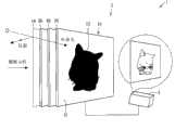
图1是将显示面板分解,示意性地表示本发明的一个实施方式的显示系统的概略结构的分解立体图。FIG. 1 is an exploded perspective view schematically showing a schematic configuration of a display system according to an embodiment of the present invention by disassembling a display panel.
图2是表示本发明的一个实施方式的显示面板的有源矩阵基板的重要部位的概略结构的俯视图。2 is a plan view showing a schematic configuration of important parts of an active matrix substrate of a display panel according to an embodiment of the present invention.
图3是示意性地表示沿图2所示的A-A线截断本发明的一个实施方式的显示面板时的概略结构的一例的截面图。3 is a cross-sectional view schematically showing an example of a schematic structure of the display panel according to the embodiment of the present invention taken along the line A-A shown in FIG. 2 .
图4是示意性地表示沿图2所示的A-A线截断本发明的一个实施方式的显示面板时的概略结构的另一例的截面图。4 is a cross-sectional view schematically showing another example of the schematic structure of the display panel according to the embodiment of the present invention taken along the line A-A shown in FIG. 2 .
图5(a)、(b)分别是说明本发明的一个实施方式的显示系统的工作原理的图。5( a ) and ( b ) are diagrams illustrating the operating principle of the display system according to one embodiment of the present invention, respectively.
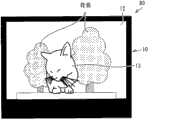
图6是表示本发明的一个实施方式的显示面板的显示图像的一例的图。FIG. 6 is a diagram showing an example of a display image of a display panel according to an embodiment of the present invention.
图7是表示在本发明的一个实施方式的显示面板的散射部内形成有透明部的情况的显示图像的一例的图。7 is a diagram showing an example of a display image when a transparent portion is formed in a scattering portion of a display panel according to an embodiment of the present invention.
图8是表示在本发明的一个实施方式的显示面板的透明部内形成有散射部的情况的显示图像的一例的图。8 is a diagram showing an example of a display image when a scattering portion is formed in a transparent portion of a display panel according to an embodiment of the present invention.
图9是表示本发明的一个实施方式的显示系统的概略结构的一例的框图。FIG. 9 is a block diagram showing an example of a schematic configuration of a display system according to an embodiment of the present invention.
图10是表示本发明的一个实施方式的显示系统中的显示装置的视频控制部的电路结构的框图。10 is a block diagram showing a circuit configuration of a video control unit of a display device in a display system according to an embodiment of the present invention.
图11是表示1帧的结构的图。FIG. 11 is a diagram showing the structure of one frame.
图12是表示用于手动将显示面板的图像和投影仪的图像位置对齐的图案(pattern)的图。FIG. 12 is a diagram showing a pattern for manually aligning an image on a display panel with an image on a projector.
图13是表示自动将显示面板的图像和投影仪的图像位置对齐的情况下的本发明的一个实施方式的显示系统的概略结构的一例的框图。FIG. 13 is a block diagram showing an example of a schematic configuration of a display system according to an embodiment of the present invention when automatically aligning an image on a display panel with an image on a projector.
图14是表示自动将显示面板的图像和投影仪的图像位置对齐的情况下的本发明的一个实施方式的显示系统的概略结构的另一例的立体图。14 is a perspective view showing another example of a schematic configuration of a display system according to an embodiment of the present invention when automatically aligning an image on a display panel with an image on a projector.
图15是表示自动将显示面板的图像和投影仪的图像位置对齐的情况下的本发明的一个实施方式的显示系统的概略结构的又一例的立体图。15 is a perspective view showing still another example of a schematic configuration of a display system according to an embodiment of the present invention when automatically aligning an image on a display panel with an image on a projector.
图16是表示自动将显示面板的图像和投影仪的图像位置对齐的情况下的本发明的一个实施方式的显示系统的概略结构的又一例的立体图。16 is a perspective view showing still another example of a schematic configuration of a display system according to an embodiment of the present invention when automatically aligning an image on a display panel with an image on a projector.
图17是表示本发明的一个实施方式的显示系统的概略结构的另一例的框图。FIG. 17 is a block diagram showing another example of a schematic configuration of a display system according to an embodiment of the present invention.
图18(a)是表示设本发明的一个实施方式的显示面板的入射侧的折射率为1、该显示面板的表面的相对折射率为1.45时的透过率与光的入射角度的关系的图表,(b)是表示设本发明的一个实施方式的显示面板的入射侧的折射率为1、该显示面板的表面的相对折射率为1.65时的透过率与光的入射角度的关系的图表。18( a ) is a graph showing the relationship between the transmittance and the incident angle of light when the refractive index of the incident side of the display panel according to one embodiment of the present invention is 1 and the relative refractive index of the surface of the display panel is 1.45. Graph (b) shows the relationship between the transmittance and the incident angle of light when the refractive index of the incident side of the display panel according to one embodiment of the present invention is 1, and the relative refractive index of the surface of the display panel is 1.65. chart.
图19是表示正常模式(normal mode)的PDLC层的液晶滴(droplet)的排列方向的截面图。19 is a cross-sectional view showing the arrangement direction of liquid crystal droplets (droplets) in a PDLC layer in a normal mode.
图20是表示反转模式(reverse mode)的PDLC层的液晶滴的排列方向的截面图。20 is a cross-sectional view showing the alignment direction of liquid crystal droplets in a PDLC layer in a reverse mode.
图21是表示对本发明的效果进行了实证实验的结果的图。Fig. 21 is a graph showing the results of a demonstration experiment on the effects of the present invention.
图22是表示对本发明的效果进行了实证实验的结果的另一图。Fig. 22 is another diagram showing the results of empirical experiments on the effects of the present invention.
图23(a)是表示在光源装置设置有ND滤镜时的本发明的一个实施方式的显示系统中的显示面板表面的散射显示的样子的截面图,(b)是表示在(a)所示的显示系统没有设置ND滤镜的情况的显示面板表面的散射显示的样子的截面图。23( a ) is a cross-sectional view showing a state of scattered display on the surface of the display panel in a display system according to an embodiment of the present invention when the light source device is provided with an ND filter, and ( b ) is a cross-sectional view showing the state shown in ( a ). A cross-sectional view of a state of scattered display on the surface of the display panel in the case where the display system shown is not provided with an ND filter.
图24是示意性地表示从显示面板的前面侧观看使用了多个光源装置的本发明的一个实施方式的显示系统时的概略结构的正面图。24 is a front view schematically showing a schematic configuration of a display system according to an embodiment of the present invention using a plurality of light source devices viewed from the front side of the display panel.
图25是使用了多个显示面板的本发明的一个实施方式的显示装置的鸟瞰图。FIG. 25 is a bird's-eye view of a display device according to an embodiment of the present invention using a plurality of display panels.
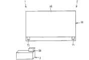
图26是示意性地表示使用了本发明的一个实施方式的显示系统的电子相框(Photo Frame)的概略结构的正面图。FIG. 26 is a front view schematically showing a schematic structure of an electronic photo frame (Photo Frame) using a display system according to an embodiment of the present invention.
图27(a)、(b)分别是表示使用了本发明的一个实施方式的显示系统的便携式电话的概略结构的正面图。27( a ) and ( b ) are front views each showing a schematic configuration of a mobile phone using a display system according to an embodiment of the present invention.
图28是表示图27所示的便携式电话的概略结构的背面立体图。Fig. 28 is a rear perspective view showing a schematic configuration of the mobile phone shown in Fig. 27 .
图29是表示图27(a)、(b)和图28所示的便携式电话的概略结构的截面图。Fig. 29 is a sectional view showing a schematic structure of the mobile phone shown in Fig. 27(a), (b) and Fig. 28 .
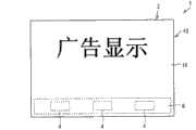
图30是示意性地表示使用了本发明的一个实施方式的显示系统的电子设备的一例的图。FIG. 30 is a diagram schematically showing an example of electronic equipment using a display system according to an embodiment of the present invention.
具体实施方式Detailed ways
以下,对本发明的实施方式进行详细说明。Hereinafter, embodiments of the present invention will be described in detail.
[实施方式1][Embodiment 1]
图1是将显示面板分解,示意性地表示本发明的一个实施方式的显示系统的概略结构的分解立体图。另外,图2是表示本实施方式的显示面板的有源矩阵基板的重要部位的概略结构的俯视图。另外,图3是示意性地表示沿图2所示的A-A线截断本发明的一个实施方式的显示面板时的概略结构的一例的截面图。图9是表示本发明的一个实施方式的显示系统的概略结构的一例的框图。FIG. 1 is an exploded perspective view schematically showing a schematic configuration of a display system according to an embodiment of the present invention by disassembling a display panel. In addition, FIG. 2 is a plan view showing a schematic configuration of important parts of the active matrix substrate of the display panel according to the present embodiment. In addition, FIG. 3 is a cross-sectional view schematically showing an example of a schematic structure of the display panel according to the embodiment of the present invention taken along the line A-A shown in FIG. 2 . FIG. 9 is a block diagram showing an example of a schematic configuration of a display system according to an embodiment of the present invention.
另外,在本实施方式中,本实施方式的显示系统主要举出具有投影仪作为光源装置(投影机)的情况为例说明,但本实施方式并不限定于此。作为上述光源装置,能够使用投影(照射)单色或多色的光的各种光源装置,上述光不一定要是视频(图像)。另外,在以下说明中,也可称“投影仪”为“光源装置”。In addition, in the present embodiment, the display system of the present embodiment is mainly described by taking a case where a projector is provided as the light source device (projector) as an example, but the present embodiment is not limited thereto. Various light source devices that project (irradiate) monochromatic or polychromatic light can be used as the light source device, and the light does not necessarily have to be video (image). In addition, in the following description, a "projector" may also be referred to as a "light source device".
如图1和图9等所示,本实施方式的显示系统1(液晶显示系统)包括:具有能够实现光散射状态和光透过状态的PDLC面板10(显示部、显示面板)的显示装置2;和作为对上述PDLC面板10进行光照射的光源装置的投影仪3。As shown in FIG. 1 and FIG. 9, etc., the display system 1 (liquid crystal display system) of this embodiment includes: a
首先,对显示装置2的概略结构进行说明。First, a schematic configuration of the
上述显示装置2例如如图9所示,在作为显示面板的上述PDLC面板10以外,作为对上述PDLC面板10的显示及其定时(timing)进行控制的控制部,具有例如数据接收部51、数据接收控制部52、运算控制部53、视频控制部54、存储部55、操作部56等。另外,关于这些PDLC面板10以外的结构在后面详述。For example, as shown in FIG. 9 , the above-mentioned
在使用显示视频(图像)的投影仪3作为光源装置的情况下,PDLC面板10被用作显示从投影仪3放映(投影)的视频(着色图像)的屏幕。In the case of using the
PDLC面板10是在作为观察者侧的基板的前面基板和与观察者侧相反的一侧的背面基板之间夹持有PDLC(Polymer Dispersed LiquidCrystal:高分子分散型液晶)层40作为显示介质层(光散射层、液晶层、光调制层)的液晶面板。In the
PDLC具有液晶呈微滴状分散在聚合物中的结构,具有根据有无电场的施加来切换光透过状态和光散射状态的性质。在正常模式的PDLC面板10中,PDLC在无电场施加时使光散射,当施加电场时,使光透过而变得透明。另一方面,在反转模式的PDLC面板10中,PDLC在无电场施加时使光透过,当施加电场时,通过使光散射而变得非透明。另外,关于正常模式和反转模式,在后面详述。PDLC has a structure in which liquid crystals are dispersed in a polymer in the form of droplets, and has the property of switching between a light-transmitting state and a light-scattering state depending on whether an electric field is applied or not. In the normal
因此,PDLC面板10能够根据施加到PDLC的电场的大小、具体而言是对PDLC有无电场的施加来切换光透过状态和光散射状态。Therefore, the
在本实施方式中,通过对这种PDLC面板10进行有源矩阵驱动,实现局部的光散射状态。In the present embodiment, by performing active matrix driving on such a
即,本实施方式的PDLC面板10是一种有源矩阵型的液晶面板,如图2所示,多个像素11呈矩阵状排列,并且在各像素11具有例如TFT(Thin Film Transistor:薄膜晶体管)22作为开关元件,通过该TFT22对各像素11的电场的施加(例如有无电场的施加)进行控制。That is, the
本实施方式的PDLC面板10,如图1和图2所示,具有如下结构:在多个像素11(参照图2)呈矩阵状排列的基板20(有源矩阵基板、阵列基板、第一基板)和与该基板20相对配置的基板30(对置基板、第二基板)之间,夹持有PDLC层40作为能够实现光散射状态和光透过状态的显示介质层(光散射层、液晶层)。The
另外,在以下说明中,举出如图1所示作为对置基板的基板30是前面基板,作为有源矩阵基板的基板20是背面基板的情况为例说明。但是,本发明并不限定于此。In addition, in the following description, the case where the
另外,在本实施方式中,列举了作为基板20(有源矩阵基板)设置有由TFT(Thin Film Transistor:薄膜晶体管)构成的开关元件的TFT基板的例子进行说明,但本实施方式并不限定于此。In addition, in this embodiment, an example of a TFT substrate provided with a switching element composed of a TFT (Thin Film Transistor: thin film transistor) is given as the substrate 20 (active matrix substrate) for description, but this embodiment is not limited here.
如图3所示,基板20具有玻璃基板等透明基板21作为绝缘基板(显示介质层保持材料、基底基板)。As shown in FIG. 3 , the
在透明基板21上设置有多个TFT22和像素电极23,并且设置有源极配线24、栅极配线25、Cs配线26(辅助电容配线)等多个配线。A plurality of
另外,TFT22的结构与现有相同,另外,栅极绝缘膜和层间绝缘膜等也是众所周知的,因此关于TFT22的详情以及栅极绝缘膜、层间绝缘膜等省略图示。In addition, the structure of the
像素电极23为透明电极,由例如ITO(铟锡氧化物)等具有透光性的导电性材料形成。如图2所示,像素电极23相互隔开间隔配置,对成为图像显示的一个单元的像素11进行规定。The
TFT22的源极电极(未图示)、栅极电极(未图示)、漏极电极(未图示),分别与栅极配线24、栅极配线25、像素电极23连接,源极配线24经由TFT22与像素电极23连接。另外,栅极配线25有选择地使TFT22动作。Cs配线26设置成与像素电极23相对,以使在与像素电极23重叠的部分形成辅助电容。The source electrode (not shown), the gate electrode (not shown), and the drain electrode (not shown) of the
源极配线24和栅极配线25,如图2所示,从基板30(参照图1)的法线方向)观看时交叉,分别与设置于基板20的未图示的驱动电路的源极驱动器和栅极驱动器连接。The
这些源极配线24、栅极配线25、Cs配线26,一般用钽等遮蔽光的金属材料形成。The
如图3所示,基板30具有玻璃基板等透明基板31作为绝缘基板(显示介质层保持材料、基底基板)。As shown in FIG. 3 , the
在透明基板31上设置有黑矩阵32(遮光膜)和由ITO等透明导电膜构成的对置电极33。黑矩阵32根据需要配置成:在相邻的像素11·11间和显示区域的周边对源极配线24、栅极配线25、Cs配线26等配线和TFT22进行遮光。A black matrix 32 (light-shielding film) and a
在上述PDLC面板10中,通过对施加到PDLC层40的电场,换言之,对施加到上述对置电极33和像素电极23之间的电压进行控制,能够使PDLC层40在光散射状态和光透过状态之间转换。In the above-mentioned
上述PDLC面板10不具有CF(彩色滤光片、着色层),通过利用TFT22控制对PDLC有无电场的施加,如图1所示,有选择地形成作为光透过区域的透明部12和作为光散射区域的散射部13。The above-mentioned
在上述显示系统1中,将光(图像)从例如投影仪3投影到上述PDLC面板10上,在上述散射部13上显示从投影仪3投影的图像,由此进行仿佛显示图像从PDLC面板10的表面浮出到空中的显示。此时,来自配线的直接反射,很大地损害显示图像浮出到空中的表现。In the above-mentioned
因此,在上述PDLC面板10中,如图1和图3所示,从观察者观看时在比上述配线靠近跟前的位置,例如设置如上所述覆盖配线的黑矩阵32(遮光膜)和作为光散射层的上述PDLC层40。由此,在主要的观察方向上能够遮蔽上述配线对外部光的直接反射。其结果,能够进行显示图像从PDLC面板10的表面浮出这样的独特的显示。Therefore, in the
另外,上述遮光膜和PDLC层40的厚度并未特别限定,但例如上述黑矩阵32的厚度,在为了得到TFT22的遮光所需的光学浓度(OD=2~4),使用铬时优选为0.2μm程度,使用黑抗蚀剂(black resist)时优选为1~2μm程度。另外,PDLC层40的厚度,为了实现后述的光散射状态的透过率(0.1%~30%),优选在3μm~20μm的范围内,为了实现后述的光透过状态的透过率(40%~90%)和光散射状态的透过率(0.1%~30%),更加优选在3μm~15μm的范围内。In addition, the thicknesses of the above-mentioned light-shielding film and the
另外,在上述说明中,如图3所示,以如下情况为例进行了说明:在透明基板31和对置电极33之间设置有由黑矩阵32构成的遮光膜,并且使用设置有上述黑矩阵32的基板30作为前面基板,由此从观察者观看时依次设置有黑矩阵32/PDLC层40(光散射层)/源极配线24、栅极配线25、Cs配线26等的配线。但是,本实施方式并不限定于此。In addition, in the above description, as shown in FIG. 3 , the following case has been described as an example: a light-shielding film composed of a
例如,使用如上所述的作为对置基板的基板30来作为前面基板的情况下,也可以在基板20的配线上(即,上述配线的与基板30相对的面一侧)设置黑矩阵等遮光膜。For example, when using the above-mentioned
像这样,在基板20设置黑矩阵的情况下,例如在上述配线上涂敷黑抗蚀剂(black resist)后通过曝光、显影,能够在上述配线上设置遮光膜。此时的黑抗蚀剂的膜厚,为了得到与在基板30设置遮光膜时同等的光学浓度(OD=2~4),设定为例如1μm。In this way, when a black matrix is provided on the
图4是示意性地表示沿图2所示的A-A线截断本实施方式的显示面板时的概略结构的另一例的截面图。4 is a cross-sectional view schematically showing another example of the schematic structure of the display panel according to the present embodiment taken along the line A-A shown in FIG. 2 .
另外,在使用作为有源矩阵基板(TFT基板)的基板20作为前面基板的情况下,如图4所示,为了降低来自作为有源矩阵基板的基板20的背面(与和PDLC层40相对的面相反一侧的面)的配线反射率,也可以在基板20的透明基板21与上述配线之间(即,上述配线的背面侧)设置氮化硅膜或薄金属膜等配线反射率降低层27(反射率降低层)。另外,在图4中,也省略了栅极绝缘膜和层间绝缘膜等绝缘膜的图示。In addition, in the case of using the
另外,上述配线反射率降低层27的厚度并未特别限定,只要根据配线反射率降低层27的材料等适当设定成能够进行如上所述显示图像从PDLC面板10的表面浮出到空中的显示即可。In addition, the thickness of the above-mentioned wiring
本申请发明者们确认后的结果,如上所述使用基板20作为前面基板,通过在蒸镀有50nm厚的氮化硅膜作为配线反射率降低层27的透明基板21(具体而言是玻璃基板)上制作上述配线,能够使来自作为前面基板的基板20的背面(与PDLC层40相对的一面相反一侧的面)的配线反射率减半。As a result of confirmation by the inventors of the present application, using the
另外,更加优选的是,通过在蒸镀有25nm厚的氧化钛膜作为配线反射率降低层27的透明基板21(具体而言是玻璃基板)上制作上述配线,能够将来自上述配线的反射率降低到1/20。In addition, it is more preferable that by forming the above-mentioned wiring on the transparent substrate 21 (specifically, a glass substrate) on which a 25 nm-thick titanium oxide film is vapor-deposited as the wiring
进一步优选的是,通过在制作有蒸镀160nm厚的氟化镁膜并在其上蒸镀25nm厚的氧化钛膜而成的配线反射率降低层27的透明基板21(具体而言是玻璃基板)上制作上述配线,将来自上述配线的反射率降低到大约1/50。More preferably, the transparent substrate 21 (specifically glass substrate) to reduce the reflectance from the above wiring to about 1/50.
在如上所述使用金属膜作为上述配线反射率降低层27的情况下,该金属膜被设置成仅覆盖上述配线的背面或根据需要仅覆盖上述配线的背面及其周边部。When a metal film is used as the wiring
另一方面,在如上所述使用氮化硅膜作为上述配线反射率降低层27的情况下,该氮化硅膜可以设置在上述基板20的显示区域整个区域,也可以被设置成仅覆盖上述配线的背面或根据需要仅覆盖上述配线的背面及其周边部。On the other hand, in the case where a silicon nitride film is used as the wiring
另外,在PDLC面板10的至少一个表面(即,基板20、30中至少一个基板的与和PDLC层40相对的面相反的一侧的表面),如图1所示,为了抑制、防止因外部光导致的基板表面的反射(即,基板20、30的表面反射),设置有反射防止膜14。In addition, on at least one surface of the PDLC panel 10 (that is, the surface of at least one of the
另外,优选上述反射防止膜14设置在上述一对基板20、30中的至少作为观察者侧的基板的前面基板的表面。In addition, it is preferable that the
作为上述反射防止膜14,能够优选使用因干涉而抑制了反射的AR(Anti Reflective:防反射)膜和LR(Low Reflective:低反射)膜、在表面具有被称为蛾眼的曲线上的突起且在厚度方向的折射率连续地变化的所谓蛾眼(Moth eye)结构的无反射膜等。As the above-mentioned
为了进行使显示图像浮出到空中的三维的显示,理想的是在什么都没有的空间显示像。In order to perform three-dimensional display in which a display image floats in the air, it is desirable to display an image in a space where there is nothing.
但是,只要在使用玻璃等的基板上进行显示,就会通过基板的表面反射(在基板的法线方向为约4%)而映入外部光。However, as long as the display is performed on a substrate using glass or the like, external light is reflected by the surface reflection of the substrate (approximately 4% in the normal direction of the substrate).
外部光即使映入到作为显示图像的部分的散射部13也不会引人注意,视觉的影响小。但是,当外部光映入到透明部12即不利用从投影仪3等光源装置投射的光显示图像的非显示部分时,会对看到显示到散射部13的图像浮出到空中的效果产生较大的损害。Even if external light is reflected on the scattering
在PDLC面板10从观察者观看时在比配线靠近跟前的位置不具有如上所述用于防止配线的直接反射的结构的情况下,在不对PDLC面板10的表面做任何处理时,只会看到如在玻璃的表面画了画那样的显示。When the
但是,通过如上所述在PDLC面板10的表面设置反射防止膜14,能够抑制、防止基板20、30的表面的外部光的反射,进行散射部13的图像(视频)浮出到空中那样的三维的独特的显示。However, by providing the
像这样,作为用于抑制妨碍进行显示图像浮出到空中的三维显示的外部光的反射的结构,在上述PDLC面板10设置有下述(1)和(2)的结构中的至少一个结构。In this way, as a structure for suppressing reflection of external light that hinders three-dimensional display in which a display image floats in the air, the
(1)选自抑制配线的直接反射的、从观察者观看时设置在比配线靠近跟前的位置的遮光膜、配线反射率降低层27和PDLC层40(光散射层)中的至少一种,(1) At least one selected from the group consisting of a light-shielding film that suppresses direct reflection of the wiring and that is placed closer to the wiring when viewed by an observer, the wiring
(2)抑制基板表面的反射的反射防止膜14,(2)
这些(1)的用于抑制配线的直接反射的结构和(2)的用于抑制基板表面的反射的结构,可以仅设置任一个,但优选两个都设置。在设置有这些结构(1)和(2)两者的情况下,通过一并具有上述两者的功能,因其协同效应,能够进行散射部13的图像浮出到空中的显示的上述效果更加显著。Only one of (1) the structure for suppressing direct reflection of wiring and (2) the structure for suppressing reflection on the substrate surface may be provided, but both are preferably provided. In the case where both of these structures (1) and (2) are provided, the above-mentioned effect of enabling the display of the image of the
另外,PDLC在大多情况下具有在太阳光等紫外线下劣化的弱点。In addition, PDLC has a weak point of being degraded by ultraviolet rays such as sunlight in many cases.
因此,在如上所述在PDLC面板10的表面设置反射防止膜14的情况下,为了使该反射防止膜14具有UV吸收性等作为反射防止膜14的特性,优选对反射防止膜14实施不使UV光透过的处理。Therefore, in the case where the
另外,在不使用反射防止膜14的情况下,希望将实施了使其具有UV吸收性等使UV光不透过的处理的膜设置在PDLC面板10的表面,或者至少在一个基板表面直接实施不使UV光透过的处理。In addition, in the case where the
进一步,希望对上述基板20、30两者实施对这些UV光的对策。Furthermore, it is desirable to take countermeasures against these UV light on both the above-mentioned
[显示动作][show actions]
接着,对上述显示系统的显示动作进行说明。Next, the display operation of the above-mentioned display system will be described.
在上述显示系统1中,将PDLC面板10作为显示部(屏幕部),从投影仪3向PDLC面板10投射(照射)光(视频)。In the
通过对各像素11有选择地施加电场,在PDLC面板10有选择地形成透明部12(光透过区域)和散射部13(光散射区域)。By selectively applying an electric field to each pixel 11 , transparent portions 12 (light transmission regions) and scattering portions 13 (light scattering regions) are selectively formed on the
另外,以下以施加电场时(ON时)成为光透过状态,在不施加电场时(OFF时)成为光散射状态的正常模式(Normal Mode)的情况为例进行说明,但在反转模式中,除了在施加电场时(ON)时成为光散射状态,在不施加电场时(OFF时)成为光透过状态以外,完全相同。In addition, the following describes the case of normal mode (Normal Mode) in which light is transmitted when an electric field is applied (ON) and light is scattered when no electric field is applied (OFF). , except that it becomes a light scattering state when an electric field is applied (ON), and becomes a light transmission state when an electric field is not applied (OFF).
PDLC面板10不具有CF,施加有电场的像素11以没有CF的高透过率(面板透过率)成为透明状态(透视状态)。因此,仅在散射部13利用从观察者观看时配置在PDLC面板的后方(背面侧)的投影仪3的光显示发光的视频。The
另外,在透明部12(即,透过显示的像素11)中,PDLC面板10为透明,能看到背景。In addition, in the transparent part 12 (that is, the pixel 11 for transparent display), the
PDLC面板10由于不具有CF,所以能够在散射部13显示从投影仪3投射的任意颜色的光。Since the
另外,PDLC面板10自身如上所述不显示颜色,所以不需要将像素11内三分割为RGB(分成RGB三部分)。因此,能够以高开口率设计PDLC面板10,能够以更高的透过率成为透明状态。In addition, since the
如上所述,使用投影仪3作为光源装置使投射到PDLC面板10的光成为投影仪视频的情况下,如图1所示,从投影仪3输出想映在PDLC面板10的符号(character)等视频。PDLC面板10形成将从投影仪3输出的想映在PDLC面板10的视频(例如符号)中的至少黑色以外部分的视频(例如符号)涂满的形状的散射部13。As described above, when using the
在想映在PDLC面板10的视频例如如图8所示为人物的情况下,在PDLC面板10的透明部12中能够透过看到(即,进行透过显示)的背景完全黑暗的情况下,为了表现头发等的黑色,并不一定需要在散射部13映出黑色的视频。在这种情况下,为了表现黑色,只要使黑色的部分成为透明部12,在该透明部12透过显示背景的黑色即可。In the case where the video to be projected on the
但是,在成为PDLC面板10的背景的PDLC面板10的后方明亮的情况下,通过形成将从投影仪3输出的想映到PDLC面板10的视频(例如符号)涂满的形状的散射部13,能够防止灰度等级的反转,能够表现头发等的黑色。因此,在这种情况下,形成将例如从投影仪3输出的符号等涂满的形状的散射部13。However, when the rear of the
即,在PDLC面板10中,显示与背景相同颜色的视频的部分,不必形成散射部13而只要使之成为透明部12即可,至少在显示与背景不同的颜色的视频的部分,形成将该视频涂满的形状的散射部13。That is, in the
另外,在如上所述背景明亮时,在正常模式下,优选散射部13同样地为0灰度等级,但在背景暗的情况下,也可以以灰度等级不反转的程度对散射部13施加电压。In addition, when the background is bright as described above, in the normal mode, it is preferable that the scattering
像这样,PDLC面板10在散射部13映出从投影仪3等光源装置投射的视频,使PDLC面板10的背景透过显示在透明部12,由此将PDLC面板10的背景和从投影仪3等光源装置投射的视频合成显示。In this way, the
[动作原理][Action principle]
接着,对上述显示系统1的动作原理进行说明。Next, the principle of operation of the
图5的(a)、(b)是说明上述显示系统1的动作原理的图。图5(a)表示PDLC面板10的PDLC层40被控制为光透过状态的情况的显示系统1的动作原理,图5(b)表示PDLC面板10的PDLC层40被控制为光透过状态的情况的显示系统1的动作原理。(a) and (b) of FIG. 5 are diagrams illustrating the principle of operation of the
另外,在以下说明中,以在PDLC面板10的后方(背景)配置有物体301,PDLC面板10的后方(背景)不是完全黑暗而是因照明等的外部光而明亮的情况为例进行说明。In addition, in the following description, the case where
首先,以如上所述使用投影仪3作为图5(a)、(b)所示的光源装置4的情况为例进行说明。First, a case where the
如图5(a)所示,在将PDLC面板10的PDLC层40控制为光透过状态时,从观察者观看时在PDLC面板10的后方的物体301的角302反射而入射到PDLC面板10的光(图像),在位置P1透过而不散射,所以物体301的像(图像)很清楚地到达观察者。As shown in FIG. 5( a), when the
另一方面,如图5(b)所示,在上述物体301的角302反射而入射到PDLC面板10的光,在上述位置P1散射。On the other hand, as shown in FIG. 5( b ), the light reflected at the
此时,在被物体301反射的光,由于没有指向性,所以也到达PDLC面板10的位置P1的周边而散射。At this time, since the light reflected by the
而且,除了物体301的角302以外,被物体301的边和面反射的光也到达上述位置P1而散射。因此,PDLC面板10的后方的物体301的明确的像,不会到达观察者。Furthermore, light reflected by the sides and surfaces of the
此时,在配置在PDLC面板10的背面的光源装置4如上所述为投影仪3时,如果使焦点与PDLC面板10的例如位置P2吻合,则在位置P2散射的从投影仪3(光源装置4)投射的光,在PDLC面板10发生前方散射而到达观察者。但是,投射到位置P2的光,由于仅具有想要在该位置P2显示的明亮度和颜色的信息,所以来自投影仪3的像很清楚地到达观察者。另外,从光源装置4投射的光,在为例如如使用激光投影仪作为光源装置4时那样具有指向性的光时也同样。At this time, when the
另外,在光源装置4为投射单色光的光源装置时,也可以使焦点与PDLC面板10吻合,或是使用具有指向性的光源装置4,如上所述对PDLC面板10的光透过状态和光散射状态以及来自光源装置4的光的ON/OFF(点亮/熄灭)进行控制。In addition, when the
或者,在如上所述光源装置4为投射单色光的光源装置时,也可以设定成利用PDLC面板10的光透过状态和光散射状态来表现想要显示在PDLC面板10的像的形状,使来自光源装置4的光照射PDLC面板10整个面。但是,在这种情况下,由于来自光源装置4的光也入射到PDLC面板10的透明部12,所以希望将光源装置4设置成使来自该光源装置4的被投射的光不直接到达观察者。Alternatively, when the
根据本实施方式,如上所述,通过光源装置4使用投射带有单色或多色的颜色的光(着色光)的光源装置,能够不使用CF地进行颜色显示,并且能够通过上述的动作原理越过PDLC面板10看到PDLC面板10的背景。因此,根据本实施方式,能够不受因使用CF而导致的透过率降低的影响地实现透明性高的透视显示。According to the present embodiment, as described above, by using the
图6是表示PDLC面板10的显示图像的一例的图。FIG. 6 is a diagram showing an example of a display image of the
如图1所示使从投影仪3投射的视频显示在与由从投影仪3投射的视频的轮廓形成的形状相同的形状的散射部13,将其周围的区域作为透明部12,由此将作为放映图像的散射图像和背景的透过图像合成,图6表示此时的显示图像。As shown in FIG. 1 , the video projected from the
如上所述,在PDLC面板10的背景不是完全黑暗而是例如像点亮了照明那样的状态(即,能够视认到背景的状态)的情况下,在图6所示的合成图像中,作为放映图像的散射图像能够被看成从背景的透过图像浮出到空中。即,能够进行如放映图像从PDLC面板10的表面浮出到空中那样独特的显示。As described above, in the case where the background of the
另外,从投影仪3投射的视频,例如通过任意变更透明部12和散射部13的形状,能够任意地切出。另外,通过与背景组合,能够进行各种独特的显示。In addition, the video projected from the
图7是表示在PDLC面板10的散射部13内形成有透明部12的情况的显示图像的一例的图,示出:能够在散射部13内以任意的形状形成透明部12。图7表示从观察者观看时在PDLC面板10的后方(背景)配置有实物的鞋子303(商品)作为上述物体301的例子。7 is a diagram showing an example of a display image when
另外,图8与图7相反,是表示在PDLC面板10的透明部12内形成有散射部13的情况的显示图像的一例的图,示出:能够以任意的形状显示视频和文字等。In contrast to FIG. 7 , FIG. 8 is a diagram showing an example of a display image when the scattering
[视频处理][Video Processing]
接着,对上述显示系统1的视频处理进行说明。Next, video processing of the
如上所述,在使用显示图像(视频)的投影仪3作为光源装置4的情况下,需要使由透明部12和散射部13形成的PDLC面板10的图像与由投影仪显示的图像同步。As described above, when using
因此,接下来对作为上述显示系统1的视频处理之一的使上述图像同步的方法进行说明。Therefore, a method of synchronizing the above-mentioned images as one of the video processing of the above-mentioned
首先,在上述说明之前,以下先参照图9对上述显示系统1的显示装置2的概略结构进行说明。First, before the above description, a schematic configuration of the
如图9所示,显示装置2除了PDLC面板10以外,还具有例如数据接收部51、数据接收控制部52、运算控制部53、视频控制部54、存储部55、操作部56。As shown in FIG. 9 ,
上述数据接收部51,通过上述数据接收控制部52的接收控制,从外部装置通过有线或无线接收视频信号(例如符号和文字混在一起的图像数据和音频数据)。此时,在假定存储卡等记录介质作为外部装置的情况下,可以从插入记录介质的槽(slot)取得上述视频信号。该接收的视频信号被发送到运算控制部53。The
上述运算控制部53根据由上述数据接收控制部52接收的视频信号,生成用于在上述PDLC面板10显示的图像。在此生成的图像,被发送到视频控制部54,并且被送到存储部55存储。该运算控制部53基于从操作部56输入的指示进行运算处理。The
上述视频控制部54,将由上述运算控制部53求得的图像,转换为用于在上述PDLC面板10中显示的图像并发送到上述PDLC面板10,并且将该图像转换为用于从上述投影仪3输出的图像并发送到上述投影仪3。The above-mentioned
在此,发送到上述PDLC面板10的图像,成为将从上述投影仪3输出的想要显示在上述PDLC面板10的图像(符号和文字等)的轮廓内部涂满的图像。例如,如图1所示,成为将包含于上述图像中的符号等涂满的图像。Here, the image transmitted to the
在具有这种显示装置2的上述显示系统1中,使用投影仪3和PDLC面板10适当地显示图像,如上所述,需要使投影仪3的图像与PDLC面板10的图像同步显示。In the
即,在使用显示图像的投影仪等作为投影仪3时,如上所述,需要使显示PDLC面板10的图像的定时(timing)与显示投影仪3的图像的定时吻合。That is, when using a projector or the like that displays an image as the
[定时控制][Timing control]
图10表示如上所述使用投影仪3作为光源装置4的情况的上述视频控制部54的电路结构。另外,图11表示1帧的结构。FIG. 10 shows a circuit configuration of the
上述视频控制部54,如图10所示,具有:显示控制电路61;用于根据从上述显示控制电路61发送的数据信号使图像显示在PDLC面板10的面板显示控制电路62;用于根据从上述显示控制电路61发送来的数据信号使图像输出到投影仪3的光源显示控制电路63;和用于将显示控制信号发送到上述面板显示控制电路62和光源显示控制电路63的反馈电路64,该显示控制信号用于使通过上述面板显示控制电路62使图像显示在PDLC面板10的定时与通过上述光源显示控制电路63使图像输出到投影仪3的定时吻合。The above-mentioned
另外,将音频数据作为音频输出的音频输出部(未图示),与运算控制部53和上述反馈电路64连接。Also, an audio output unit (not shown) that outputs audio data as audio is connected to the
上述显示控制电路61,根据运算控制部53求得的图像,生成表示用于在上述PDLC面板10中显示的图像的信号(即按每帧表示各像素11的灰度等级的数据信号),并将其发送到上述面板显示控制电路62。The
另外,上述显示控制电路61,根据运算控制部53求得的图像,生成表示用于从上述投影仪3输出的图像的信号(即按每帧表示各像素11的各色的灰度等级的数据信号),并将其发送到上述光源显示控制电路63。In addition, the
另外,上述数据信号,与用于识别对应的帧的帧识别信号一起,被送到上述面板显示控制电路62和上述光源显示控制电路63。这种情况的发送数据信号的定时为:例如图11所示,在1帧中的前半的期间发送数据信号,在后半的空白期间发送上述帧识别信号。即,将数据信号和帧识别信号作为1帧的量的数据发送到各电路。In addition, the data signal is sent to the panel
上述面板显示控制电路62和光源显示控制电路63,在被发送来的1帧的量的数据中,将帧识别信号分别发送到反馈电路64。然后,反馈电路64根据送来的各自的帧识别信号判定是否为用于识别两者是相同帧的信号,在判定为相同的情况下,对上述面板显示控制电路62和光源显示控制电路63发送用于同时显示图像的显示控制信号。The above-mentioned panel
上述面板显示控制电路62,利用发送来的显示控制信号,将已发送来的数据信号发送到PDLC面板10,在上述PDLC面板10显示图像。与此同时,上述光源显示控制电路63,利用发送来的显示控制信号,将已发送来的数据信号发送到投影仪3,在上述投影仪3输出图像。The panel
像这样,通过使用图10所示的视频控制部54,能够在上述显示系统1中使PDLC面板10的图像与投影仪3的图像同步显示。在这种情况下,仅在PDLC面板10的散射部13显示从投影仪3输出的图像,上述PDLC面板10的透明部12能够以没有CF的高面板透过率成为透明状态(透视状态)。In this way, by using the
由此,能够进行图像(视频)相对于PDLC面板10的后方(背侧)的背景浮出的显示,并且能够使这种显示与音频同步。Thereby, it is possible to display an image (video) floating from the background behind (back side) of the
另外,在上述PDLC面板10中,在上述散射部13进行利用从上述投影仪3投射的光的图像显示。因此,如上所述通过从上述投影仪3仅对形成于上述PDLC面板10的散射部13投射光,能够进行很清楚的高精细的显示,并且减少消耗电力。In addition, in the
[位置对齐][position alignment]
另外,为了如上所述在散射部13适当地显示投影仪3的图像,需要使PDLC面板10的散射部13与投影仪3的图像互相重叠。In addition, in order to properly display the image of the
因此,接着对在上述显示系统1中进行PDLC面板10的图像与投影仪3的图像的位置对齐的方法进行说明。Therefore, a method for aligning the image of the
作为上述位置对齐的方法,可以列举手动进行的方法和自动进行的方法。As the method of the above-mentioned positional alignment, a method performed manually and a method performed automatically can be mentioned.
[手动的位置对齐][manual position alignment]
例如,在具有图9所示的结构的显示系统1中,用户手动进行位置对齐。For example, in the
图12是表示用于手动将PDLC面板10的图像和投影仪3的图像位置对齐的图案(pattern)的图。FIG. 12 is a diagram showing a pattern for manually aligning the image of the
在这种情况下,将例如图12所示的具有中心点、纵线、横线和斜线的图案通过PDLC面板10和投影仪3两者,以与显示画面尺寸同等以下的尺寸显示。In this case, for example, a pattern having a center point, vertical lines, horizontal lines, and oblique lines as shown in FIG.
而且,在设置PDLC面板10和投影仪3时,调整两者的位置、角度、焦点和梯形失真等以使PDLC面板10与来自投影仪3的视频的中心点、纵线、横线和斜线重叠。由此,能手动进行上述位置对齐。And, when setting
[自动位置对齐][Auto Position Alignment]
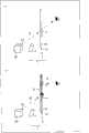
接着,以下参照图13~图16对自动进行上述位置对齐的方法进行说明。Next, a method for automatically performing the above-mentioned alignment will be described below with reference to FIGS. 13 to 16 .
图13是表示用于自动进行上述位置对齐的显示系统1的概略结构的一例的框图。另外,图14~图16分别是表示自动进行上述位置对齐的显示系统1的概略结构的另一例的立体图。FIG. 13 is a block diagram showing an example of a schematic configuration of the
如上所述,在自动进行上述位置对齐的情况下,例如图13所示,通过在显示装置2设置用于取得PDLC面板10相对于投影仪3的位置信息或投影仪3相对于PDLC面板10的位置信息的位置信息取得部57,能够自动进行上述位置对齐。As described above, in the case of automatically performing the above-mentioned position alignment, for example, as shown in FIG. The position
或者,如图14所示,也可以在PDLC面板10的显示区域16外,设置回归反射板71·71,并且在投影仪3设置具有受光元件和发光元件的传感器58,由此通过上述传感器58的受光元件接受来自上述回归反射板71·71的反射光,并且根据上述传感器58的输出值检测位置信息。Alternatively, as shown in FIG. 14 , a
另外,如图15所示,也可以在上述投影仪3设置回归反射板71·71,而将具有受光元件和发光元件的传感器58设置在PDLC面板10的显示区域16外,由此通过上述传感器58的受光元件接受来自上述回归反射板71·71的反射光,并且根据上述传感器58的输出值检测位置信息。In addition, as shown in FIG. 15 , a
上述位置信息,可以根据上述传感器58的输出值用三角测量方式检测,也可以以使用激光光源(与投影仪3不同的光源)的相位差测距方式检测。The position information may be detected by triangulation based on the output value of the
通过这样的方式检测出的位置信息,被发送到图13所示的位置信息取得部57。由位置信息取得部57取得的位置信息,被发送到视频控制部54。The positional information detected in this manner is sent to the positional
上述视频控制部54,根据上述位置信息对投影仪3进行用于进行PDLC面板10的图像和投影仪3的图像的位置对齐(位置校正)的各种调整。The
具体而言,如果在伴随投影仪3相对于PDLC面板10的配置的来自投影仪3的视频产生梯形失真,则对该梯形失真进行校正;如果在投影仪3中投射光的方向偏离,则对投射方向进行校正;进而,如果上述投影仪3的焦点偏离,则对焦点进行调整。Specifically, if keystone distortion occurs in the video from the
这种位置对齐(位置校正),除了在设置PDLC面板10和投影仪3时进行以外,也可以在设置后因任何理由需要位置对齐时等,暂时性地进行。Such positional alignment (positional correction) may be performed not only when
因此,作为用于检测上述位置信息的部件的回归反射板71·71和传感器58,可以仅在进行位置对齐时暂时性地安装,也可以总是安装。另外,也可以定期地进行上述位置对齐。Therefore, the
另外,图16所示的显示系统1,在PDLC面板10的显示区域16内具备具有受光元件的传感器59(像素内传感器),并且在投影仪3设置有用于对PDLC面板10的显示区域16内的上述传感器59照射光的传感器用光源72。另外,上述传感器59与图14和图15所示的传感器58不同,不具有发光元件。In addition, the
在上述显示系统1中,从传感器用光源72在至少三处方向上照射光。像这样,通过上述PDLC面板10具有作为像素内传感器的上述传感器59,能够检测传感器用光源72在PDLC面板10的显示区域16内的哪个位置照射了光。其结果是,能够准确地把握上述显示区域16内的透明部12和散射部13的位置。In the
因此,根据上述显示系统1,能够正确地调整上述显示区域16内的透明部12和散射部13的偏移,所以能够得到PDLC面板10的图像与投影仪3的图像的位置不偏离的最适当的视频。Therefore, according to the above-mentioned
另外,在图16所示的例子中,如上所述以在作为光源装置4的投影仪3设置有传感器用光源72的情况为例进行了说明,但并不一定需要上述传感器用光源72。In addition, in the example shown in FIG. 16 , the case where the
在光源装置4不设置传感器用光源72的情况下,通过从光源装置4在上述PDLC面板10的显示区域16的3个以上的多个方向上照射光,进行与上述同样的处理,能够检测光源装置4在PDLC面板10的显示区域16内的哪个位置照射光。因此,在这种情况下,也能够准确地把握上述显示区域16内的透明部12和散射部13的位置。When the
另外,与是否使用传感器用光源72无关地,通过将在PDLC面板10的像素11内的传感器59得到的位置信息发送到投影仪3等光源装置4,来调整光源装置4的光的照射方向、失真以及根据需要调整焦距而不改变PDLC面板10的显示位置,由此能够得到最适当的视频。In addition, regardless of whether the sensor light source 72 is used or not, by transmitting the position information obtained by the sensor 59 in the pixel 11 of the
另外,在上述说明中,对光源装置4例如使用投影仪3,对进行PDLC面板10的图像和投影仪3的图像的位置对齐的方法进行了说明。In addition, in the above description, the method of aligning the image of the
但是,在PDLC面板10的显示区域16的整个面投射光的情况下,不需要进行PDLC面板10的图像和投影仪3的图像的位置对齐。另外,例如PDLC面板10显示静止画的情况等,例如光源装置4使用LED等且在PDLC面板10的显示区域16整个面或一部分区域投射单色或多色的光的情况,也不需要进行PDLC面板10的图像与投影仪3的图像的位置对齐。或者,在仅在散射部13的一部分区域显示图像的情况下,也如上所述,不需要进行PDLC面板10的图像和投影仪3的图像的位置对齐。However, when light is projected on the
但是,在这种情况下,例如,上述视频控制部54不需要将由运算控制部53求得的图像转换为用于从光源装置4输出的图像并发送到光源装置4。However, in this case, for example, the
因此,在这种情况下,能够使用例如具有图17所示的结构的显示系统1。Therefore, in this case, for example, the
[光源光入射角度][Light source light incident angle]
接着,对上述显示系统1的光从投影仪3向PDLC面板10入射的角度进行说明。Next, an angle at which light of the above-mentioned
显示面板所使用的绝缘基板的折射率(相对于空气的绝对折射率的相对折射率),通常在约1.45~1.65的范围内。The refractive index (relative refractive index with respect to the absolute refractive index of air) of the insulating substrate used for the display panel is generally in the range of about 1.45 to 1.65.
图18(a)、(b)分别表示设PDLC面板10的入射侧的折射率为1、PDLC面板10的表面的相对折射率n为(a)1.45或(b)1.65时的透过率与光的入射角θ(入射角度)的关系。18 (a) and (b) respectively show the transmittance and the relative refractive index n when the incident side of the
更具体地说,图18(a)所示的例子表示在前面基板和背面基板使用相对于空气的绝对折射率的相对折射率为1.45的石英玻璃时的面板透过率的光的入射角依赖性。另外,图18(b)所示的例子表示在前面基板和背面基板使用相对于空气的绝对折射率的相对折射率为1.65的包含PES(聚醚砜)的塑料基板时的面板透过率的光的入射角度依赖性。More specifically, the example shown in FIG. 18(a) shows the dependence of the panel transmittance on the incident angle of light when quartz glass with a relative refractive index of 1.45 relative to the absolute refractive index of air is used for the front substrate and the rear substrate. sex. In addition, the example shown in FIG. 18(b) shows the change in panel transmittance when a plastic substrate including PES (polyethersulfone) having a relative refractive index to the absolute refractive index of air of 1.65 is used for the front substrate and the rear substrate. Angle of incidence dependence of light.
另外,在图18(a)、(b)中,Tp表示PDLC面板10的与光的入射面平行的偏振成分(P偏振光)的透过率,Ts表示PDLC面板10的与光的入射面垂直的偏振成分(S偏振光)的透过率。另外,入射角θ表示在从作为光源装置4的投影仪3远离PDLC面板10的一侧,即从投影仪3入射到PDLC面板10的光(投射光)的入射角度最大的角度。In addition, in FIG. 18(a) and (b), Tp represents the transmittance of the polarization component (P polarized light) parallel to the incident surface of the light of the
如图18(a)、(b)所示,当入射角θ超过80度时透过率急剧降低,因此从投影仪3投射的光变得不再有效地入射到PDLC面板10内。但是,如图18(a)、(b)所示,如果上述入射角θ为80度,则能够得到约60%的透过率。As shown in FIGS. 18( a ) and ( b ), the transmittance decreases sharply when the incident angle θ exceeds 80 degrees, so that the light projected from the
因此,通过使上述入射角θ为80度以下,优选在75度以下,更优选在70度以下,进一步优选在65度以下,能够得到透过率高、明亮度没有不均的显示。Therefore, by setting the incident angle θ to be 80° or less, preferably 75° or less, more preferably 70° or less, and even more preferably 65° or less, a display with high transmittance and no brightness unevenness can be obtained.
另外,关于从投影仪3向PDLC面板10的入射角度,上述入射角θ,即从投影仪3向PDLC面板10的入射角度最大的角度,特别优选为布儒斯特角(以下记作“布儒斯特角θb”)以下。In addition, regarding the incident angle from the
布鲁斯特角θb是在折射率不同的物质的界面反射的光完全成为S偏振光的入射角度,设PDLC面板10的入射侧的折射率为n1,透过侧的折射率为n2时,是由θb=arctan(n2/n1)规定的角度。与入射面平行的偏振成分(P偏振光),在该角度下反射率为0。The Brewster's angle θb is the incident angle at which the light reflected at the interface of substances with different refractive indices becomes completely S-polarized light. When the refractive index of the incident side of the
另外,关于从空气中向玻璃的入射,布鲁斯特角θb为约56度。另外,关于向相对折射率为1.65的塑料基板的入射,布鲁斯特角θb为59度。In addition, Brewster's angle θb is about 56 degrees for the incidence on the glass from the air. In addition, the Brewster's angle θb is 59 degrees for the incident on the plastic substrate with a relative refractive index of 1.65.
如果合并考虑与入射面平行的偏振成分(S偏振光),则到布鲁斯特角为止透过率相对于入射角θ没有大的变化,但当超过该角度时反射率急剧上升,从投影仪3入射到PDLC面板10的光减少。If the polarization component (S polarized light) parallel to the incident plane is taken into account, the transmittance does not change greatly with respect to the incident angle θ up to Brewster's angle, but the reflectance rises sharply when the angle exceeds this angle. Light incident on the
因此,当将投影仪3设置成从投影仪3向PDLC面板10的入射角θ最大的角度大大超过布鲁斯特角时,在PDLC面板10面内变成明亮度存在不均的显示。Therefore, if the
特别是如上所述当入射角θ超过80度时,透过率急剧下降。因此,如上所述入射角θ优选为80度以下。In particular, when the incident angle θ exceeds 80 degrees as described above, the transmittance drops sharply. Therefore, the incident angle θ is preferably 80 degrees or less as described above.
[光源与配线的位置关系][Positional relationship between light source and wiring]
接着,对投影仪3与PDLC面板10的配线的位置关系进行说明。Next, the positional relationship between the
作为上述PDLC面板10,为了低消耗电力或为了能够使用通用的驱动器,优选设计成能够以例如10V进行驱动。即,PDLC面板10的材料、制造条件、单元厚度等,优选设定成能够以10V以下进行TFT驱动。The
这种PDLC面板10在处于光散射状态时,入射到面板开口部的光,例如80%在前方散射,5%在后方散射,剩下的15%因被面板内的各层(膜)反射或吸收,或者因面板内的导光而损失。When the
即,在这种PDLC面板10中大致为前方散射,所以为了有效利用来自投影仪3的光,希望将投影仪3相对于观察者设置在PDLC面板10的后方。That is, since the
在像这样使用前方散射强的PDLC面板10时,从观察者观看时将作为光源装置4的投影仪3设置在PDLC面板10的后方的方式,能够得到光源光的利用效率高、很清楚和明亮的显示图像。When the
但是,在从观察者观看时将PDLC层40配置在比配线靠近跟前的位置的情况,即,如上所述背面基板使用作为有源矩阵基板的基板20的情况下,也可以将投影仪3设置在PDLC面板10的前方。However, when the
当背面基板如上所述使用基板20时,如果从观察者观看时将投影仪3设置在该基板20的背面侧,则从投影仪3投射的光,在通过PDLC层40之前就被上述配线反射。When the
但是,在前面基板侧即从观察者观看时在基板30的前面侧设置投影仪3的情况下,在上述的各种配线(源极配线24、栅极配线25、Cs配线26),特别是Cs配线26没有被黑矩阵32完全遮光时,从投影仪3投射的光,在通过PDLC层40后被上述配线反射。However, when the
因此,像这样,在从观察者观看时没有在配线的跟前设置遮光膜,且在配线的跟前设置有PDLC层40的情况(即,如上所述设置有作为有源矩阵基板的基板20作为背面基板的情况)下,即使当将投影仪3从观察者观看时设置在PDLC面板10的前方时,也能够利用配线的反射和作为光散射层的PDLC层40的散射的效果,使来自投影仪3的光高效地到达观察者。Therefore, in this way, when viewed from an observer, no light-shielding film is provided in front of the wiring, and the
即,在将投影仪3相对于PDLC面板10设置在观察者侧的情况下,希望将上述投影仪3设置在基板30(对置基板)一侧。另外,出于来自投影仪3的光的利用效率的观点,希望从观察者观看时在配线的跟前(如上所述,特别是Cs配线26的跟前)没有设置遮光膜。That is, when the
[透过率][Transmittance]
接着,关于上述PDLC面板10的透过率,包含上述的PDLC面板10的设计(材料、制造条件、单元厚度等)的关系进行说明。Next, the relationship between the transmittance of the
上述PDLC面板10,通过使光透过状态(透明时)的透过率为40%~90%,能够得到透明性高的光透过状态,通过使光散射状态(散射时)的透过率为0.1%~30%,能够得到在进行黑显示时背景不透过的显示。The
将仅设置有透明电极的玻璃用于成对的基板(前面基板和背面基板)而做成的PDLC面板的光透过状态下,在设空气的透过率为100%时,相对于面板法线方向,能够得到79%~90%的透过率。在这样的状态下,能够得到PDLC的光的散射充分地弱、透明性高的显示。In the light-transmitting state of a PDLC panel made by using glass with only transparent electrodes as a pair of substrates (front substrate and rear substrate), when the transmittance of air is assumed to be 100%, compared to the panel method In the linear direction, a transmittance of 79% to 90% can be obtained. In such a state, the light scattering of the PDLC is sufficiently weak and a display with high transparency can be obtained.
与之相对地,在如上所述使用TFT基板的PDLC面板10(TFT面板)中,在透明树脂层和绝缘层的影响下能够得到面板开口部分的70%~80%的透过率。即,在TFT基板中,如果能得到70%×(面板开口率)以上的透过率,就能够得到透明性高的光透过状态。In contrast, in the PDLC panel 10 (TFT panel) using the TFT substrate as described above, a transmittance of 70% to 80% of the panel opening can be obtained under the influence of the transparent resin layer and the insulating layer. That is, in a TFT substrate, if a transmittance of 70%×(panel aperture ratio) or more can be obtained, a light transmission state with high transparency can be obtained.
另一方面,在光散射状态下,如果能得到30%以下的透过率,就能够得到背景不透过的显示。On the other hand, in the light-scattering state, if a transmittance of 30% or less can be obtained, a display in which the background does not pass through can be obtained.
另外,在将仅设置有透明电极的玻璃基板用于成对的基板而做成的PDLC面板的光散射状态下,透过率超过30%的部分,仅限定于因散射而使充分的光到达观察者的光源位置,进而不能够进行对电压的ON/OFF具有充分的对比感的显示。In addition, in the light scattering state of a PDLC panel made by using a glass substrate provided with only a transparent electrode as a pair of substrates, the portion where the transmittance exceeds 30% is limited to the portion where sufficient light reaches due to scattering. The position of the light source for the observer, and furthermore, it is not possible to perform a display with a sufficient sense of contrast with respect to ON/OFF of the voltage.
因此,在TFT面板中,作为更优选的光散射状态,如果能得到27%×(面板开口率)以下的透过率,就能够得到因散射而使充分的光到达观察者的光散射状态。Therefore, in a TFT panel, as a more preferable light scattering state, if a transmittance of 27%×(panel opening ratio) or less can be obtained, a light scattering state in which sufficient light reaches the observer due to scattering can be obtained.
为了实现该光透过状态和光散射状态,上述PDLC面板10的各驱动层的材料(例如PDLC、配线材料、透明导电膜材料)的选择的效果很大。但是,作为降低光散射状态的透过率的方法,存在例如增厚单元厚度(晶胞厚度)(PDLC厚度)的方法。In order to realize the light-transmitting state and the light-scattering state, the selection of materials (for example, PDLC, wiring material, and transparent conductive film material) for each driving layer of the
如果增加单元厚度,就会增加散射的距离,所以能够增强散射。但是,在PDLC面板10中,如果增厚单元厚度则驱动电压变高。If you increase the cell thickness, you will increase the scattering distance, so you can enhance the scattering. However, in the
如上所述,作为上述PDLC面板10,为了低消耗电力或为了能够使用通用的驱动器,例如希望设定能够以例如10V进行驱动的材料、制造材料、单元厚度等。As described above, for the
但是,如上所述如果增厚单元厚度,则在如上所述的10V以下的TFT驱动下,在透明状态下不能得到充分的透过率。However, if the cell thickness is increased as described above, sufficient transmittance cannot be obtained in a transparent state when the TFT is driven at 10 V or less as described above.
因此,为了实现上述光透过状态和光散射状态,上述PDLC面板10的单元厚度希望为3μm以上、15μm。Therefore, in order to realize the above-mentioned light transmission state and light scattering state, the cell thickness of the above-mentioned
[PDLC面板的制造方法][Manufacturing method of PDLC panel]
接着,对上述PDLC面板10的制造方法进行说明。Next, a method of manufacturing the
PDLC面板10,能够通过将例如聚合性单体、光聚合引发剂和正型液晶的混合物用滴下注入等封入到上述基板20·30间后,通过UV曝光(即光聚合)得到。The
另外,上述聚合性单体、光聚合引发剂、正型液晶的类型,并不特别限定,能够使用PDLC面板制造通常所用的公知材料。另外,上述混合物的组成(使用量)也可以与现有技术同样地设定,并不特别限定。因此,省略对其的说明,本领域技术人员对其有充分的知识,能够充分地实施。In addition, the types of the above-mentioned polymerizable monomer, photopolymerization initiator, and positive liquid crystal are not particularly limited, and known materials generally used in PDLC panel production can be used. In addition, the composition (use amount) of the said mixture can also be set similarly to the prior art, and is not specifically limited. Therefore, description thereof is omitted, and those skilled in the art have sufficient knowledge and can fully implement it.
另外,本实施方式的PDLC面板10,如上所述是不使用CF(无色)的结构。因此,在PDLC的曝光时,不论基板20·30的哪个基板侧曝光都没有由CF导致的UV吸收。换言之,即使是现有技术,从设置有CF的对置基板侧曝光,也没用由CF导致的UV吸收。因此,不需要非常强的照度的曝光装置,能够使用通用性高的曝光装置。In addition, the
如上所述,作为PDLC显示模式,一般来说,存在以下模式:无施加电场时为光散射状态,通过施加电场而成为光透过状态的正常模式;和无施加电场时为光透过状态,通过施加电场而成为光散射状态的反转模式。As described above, as a PDLC display mode, in general, there are the following modes: a normal mode in which a light scattering state is formed when no electric field is applied, and a light transmission state is achieved by applying an electric field; and a light transmission state is formed when an electric field is not applied, By applying an electric field, it becomes the inversion mode of the light scattering state.
作为PDLC的材料使用的上述混合物,整体显示液晶性。The above-mentioned mixture used as a material of PDLC exhibits liquid crystallinity as a whole.
正常模式的PDLC面板10,能够通过将上述混合物在上述混合物的液晶相-各向同性相转移温度(Tni)以上的温度,优选在上述混合物的液晶相-各向同性相转移温度以上且上述混合物所用的正型液晶的液晶相-各向同性相转移温度以下的温度下进行UV(紫外线)曝光来得到。The
在正常模式的PDLC面板10中,在作为上述混合物的材料的聚合性单体中使用PDLC形成时的聚合物部(通过UV聚合而相分离时聚合物浓度高的区域)不具有折射率各向异性的材料(非液晶性单体),所得到的液晶滴(droplet,液晶粒)中的液晶(液晶分子),在面板面方向上随机取向。In the
另一方面,反转模式的PDLC面板10,能够通过将上述混合物在上述混合物的液晶相-各向同性相转移温度(Tni)以下的温度,优选在上述混合物的液晶相-各向同性相转移温度以下且上述混合物结晶化温度或要得到的PDLC成为近晶层的温度以上的温度下进行UV(紫外线)曝光来得到。On the other hand, the
在反转模式的PDLC面板10中,在作为上述混合物的材料的聚合性单体中,使用PDLC形成时的聚合物部具有折射率各向异性的材料(液晶性单体),所得到的液晶滴内的液晶,以聚合物的折射率与液晶的折射率一致的方式取向。In the
作为上述PDLC面板10,在作为光散射层的PDLC层40使用正常模式的PDLC时,将从投影仪3投射的光平面投影到PDLC面板10上时,如果以液晶滴在与从该投影仪3投射的光向PDLC面板10入射的方向垂直的方向上排列的方式形成PDLC,则能够得到更有效的散射。在使用反转模式的PDLC时,将液晶滴的液晶分子的长轴与上述入射方向垂直地配置更有效。As the above-mentioned
以下,作为上述PDLC的优选方式,对如上所述使液晶滴排列的方法进行说明。Hereinafter, a method of aligning liquid crystal droplets as described above will be described as a preferred embodiment of the aforementioned PDLC.
图19是表示正常模式的PDLC层40的液晶滴41的排列方向的截面图。另外,图20是表示反转模式的PDLC层40的液晶滴41的排列方向的截面图。FIG. 19 is a cross-sectional view showing the alignment direction of
PDLC并不一定需要偏光板和取向板。因此,在上述基板20·30的与PDLC层40相对的面上,可以设置由聚酰亚胺膜等那样的有机膜或无机膜构成的取向膜,也可以不设置。PDLC does not necessarily require polarizers and orientation plates. Therefore, on the surface of the
在上述基板20·30没有进行摩擦和光取向等取向处理时,UV曝光后的PDLC的液晶滴(通过UV聚合而相分离时液晶浓度高的区域),在基板面内随机形成。When the above-mentioned
此时如果PDLC面板10为光散射状态,则从PDLC面板10的法线方向(面板法线方向)入射的光的散射光的强度,虽然受到配线的若干影响,但基本上从面板法线方向看是相等。At this time, if the
但是,如果对基板20·30的与PDLC层40相对的面实施摩擦等取向处理,将基板20·30的摩擦方向设定成互相平行或反平行,将PDLC材料和UV曝光条件设定为最适当,则如图19所示,能够使液晶滴41沿着摩擦方向与基板面平行地排列配置(排列)。However, if orientation treatment such as rubbing is carried out on the surface of the
另外,在基板20·30的表面处理(取向处理)中,可以使用形成细槽等的摩擦以外的方法。In addition, in the surface treatment (orientation treatment) of the
在图19所示的PDLC层40中,在PDLC面板10处于光散射状态时,从面板法线方向入射的光的散射光的强度,从面板法线方向看时在与液晶滴41的排列方向42垂直的方向上强烈地散射。In the
因此,在使用使液晶滴41如图19所示排列的PDLC面板作为上述PDLC面板10的情况下,优选将投影仪3设置成:在将从投影仪3投射的光平面投影到PDLC面板10上时,该从投影仪3投射的光的向PDLC面板10入射的方向43与液晶滴41的排列方向42垂直。在这种情况下,能够使入射到PDLC面板10的来自投影仪3的光更有效地散射到达观察者。Therefore, when using a PDLC panel in which
另一方面,在反转模式下,如果将基板20和基板30的摩擦方向设定为平行或反平行(平行且相反方向),则如图20所示,液晶滴41(参照图19)内的液晶分子以其长轴44与摩擦方向平行的方式取向。On the other hand, in the inversion mode, if the rubbing directions of the
在图20所示的PDLC层40中,在PDLC面板10处于光散射状态时,从面板法线方向入射的光的散射光的强度,从面板法线方向看时在与液晶分子的长轴44(长轴方向)垂直的方向上强烈地散射。In the
因此,在使用使液晶滴41内的液晶分子的长轴44如图20所示与摩擦方向平行地排列的PDLC面板作为上述PDLC面板10的情况下,优选将投影仪3设置成:在将从投影仪3投射的光平面投影到PDLC面板10上时,该从投影仪3投射的光的向PDLC面板10入射的方向43与液晶分子的长轴44垂直。在这种情况下,能够使入射到PDLC面板10的来自投影仪3的光,更有效地散射到达观察者。Therefore, in the case of using a PDLC panel in which the long axis 44 of the liquid crystal molecules in the
[实施例][Example]
接着,实际制作使用上述PDLC面板10的显示系统1,进行各种测定,将结果表示在以下。另外,以下所示的具体的材料和制造条件是为了说明本发明的效果的实验所用的一个具体例,本发明并不限定于以下的材料和制造条件。Next, the
首先,一开始,将聚合性单体、光聚合引发剂和正型液晶的混合物通过滴下注入法注入到基板20·30间。First, at the beginning, a mixture of a polymerizable monomer, a photopolymerization initiator, and a positive liquid crystal is injected between the
上述聚合性单体使用紫外线硬化性二丙烯酸酯(diacrylate)。另外,光聚合引发剂使用“IRGACURE651”(商品名,千叶公司制造)。正型液晶使用“TL213”(商品名,默克(Merck)公司制造)。另外,上述混合物的聚合性单体、光聚合引发剂、正型液晶的使用量,依次为20%、0.5%、79.5%。As the above-mentioned polymerizable monomer, ultraviolet curable diacrylate (diacrylate) is used. In addition, "IRGACURE651" (trade name, manufactured by Chiba Corporation) was used as a photopolymerization initiator. "TL213" (trade name, manufactured by Merck) was used for the positive type liquid crystal. In addition, the usage-amounts of the polymerizable monomer, the photopolymerization initiator, and the positive type liquid crystal of the above-mentioned mixture were 20%, 0.5%, and 79.5% in this order.
另外,上述基板20·30的透明基板21·31,分别使用相对折射率n为1.5的玻璃。In addition, as the
作为TFT基板的上述基板20,如图2所示,通过使一个像素11不分割地形成为正方形使开口率为80%,在作为对置基板的基板30,在基板20的与配线相对的部分形成黑矩阵32。另外,任一个基板20·30都不设置CF。The above-mentioned
另外,单元厚度通过PS(感光间隔物),设定为5μm。In addition, the cell thickness was set to 5 μm by PS (photo spacer).
接着,将输入到上述基板20·30间的混合物,在设定为30℃的温度的板(plate)上,通过截断(cut)340nm以下的波长的光的滤光片照射365nm的波长的照度为50mW/cm2的UV光,使之聚合。由此,制作出PDLC面板10。另外,上述混合物的液晶相-各向同性相转移温度(Tni)为22℃。Next, the mixture input between the above-mentioned
另外,在上述基板20·30中不进行摩擦或光取向等取向处理,制作出PDLC的液晶滴41在基板面内随机形成的PDLC面板10。在上述PDLC面板10的两表面设置有蛾眼结构的反射防止膜14。In addition, the
用大塚电子株式会社制造的LCD评价装置“LCD-520”(商品名)对通过这样的方式制作的PDLC面板10的面板法线方向的透过率(面板透过率)进行测定。其结果是,得到光散射状态下为3%,光透过状态下为63%的透过率。The transmittance (panel transmittance) of the
将该PDLC面板10作为显示部(屏幕部),设置成使设置有黑矩阵32的基板30位于观察者侧,在成为背面基板的基板20一侧的上方设置有投影仪3。The
投影仪3与PDLC面板10的位置对齐手动进行。另外,它们的连接,以图9所示的框图所示的方式进行。另外,如上所述,将未图示的音频输出部与图10所示的运算控制部53和反馈电路64连接。The positional alignment of the
然后,如上所述,通过数据接收部51从外部装置接收符号和文字混在一起的图像数据和音频数据作为视频信号,在运算控制部53中生成用于在PDLC面板10显示的图像,发送到视频控制部54。另外,在视频控制部54,将从运算控制部53发送来的图像转换为用于在PDLC面板10中显示的图像以及用于从投影仪3输出的图像,发送到PDLC面板10和投影仪3。Then, as described above, image data and audio data in which symbols and characters are mixed are received from an external device through the
另外,发送到PDLC面板10的图像(即,在PDLC面板10显示的图像),为将从投影仪3输出的图像所含的符号和文字涂满的图像。In addition, the image transmitted to the PDLC panel 10 (that is, the image displayed on the PDLC panel 10 ) is an image filled with symbols and characters included in the image output from the
然后,使用图10所示的视频控制部54,使PDLC面板10的图像与投影仪3的图像同步。其结果是,仅在PDLC面板10的散射部13,利用PDLC面板10的后方的投影仪3的光显示发光的图像,PDLC面板10的透明部12以没有CF的高面板透过率成为透明状态(透视状态)。因此,能够与音频同步进行将图像相对于面板背侧的背景浮出到空中的显示。Then, the image of the
接着,对上述反射防止膜14的效果进行实证实验,将结果表示在图21。Next, a demonstration experiment was carried out on the effect of the
在将像素三分割为RGB的区域(将像素分为RGB三区域)后的开口率55%的通用的TFT基板贴合仅形成黑矩阵的对置基板,仅在这样形成的PDLC面板10的两面的上半部分设置反射防止膜14,使显示画面的左半部分为光散射状态(散射部),使右半部分为光透过状态(透明部),通过对该PDLC面板10照射白色光,在显示画面的左半部分进行散射显示,在右半部分进行透过显示,对此时的PDLC面板10的显示图像进行摄像,图21是表示其结果的图。A general-purpose TFT substrate with an aperture ratio of 55% after dividing the pixel into three RGB regions (dividing the pixel into three RGB regions) is bonded to a counter substrate on which only the black matrix is formed, and only on both sides of the
在本实验中,从观察者观看时在上述PDLC面板10的背面侧设置黑色的丙烯酸板,在该丙烯酸板上放置剪刀,从观察者观看时从PDLC面板10的背面侧照射白色光到PDLC面板10,对设置有反射防止膜14的部分和没有设置反射防止膜14的部分的上述散射部的显示进行比较。另外,在上述反射防止膜14使用了蛾眼(蛾眼结构的反射防止膜)。In this experiment, a black acrylic plate was placed on the back side of the
其结果是,设置有反射防止膜14的上述PDLC面板10的上半部分,在透明部没有外部光的映入,能看到剪刀的柄,所以能看到散射部浮出。As a result, in the upper half of the
另一方面,没有设置反射防止膜14的上述PDLC面板10的下半部分,从观察者观看时在剪刀的跟前的部分,存在透明部的外部光反射的映入,浮出到空中的显示受到损害。On the other hand, the lower half of the
另外,通过设置反射防止膜14,能够增强散射部的明亮度。作为其理由,可以列举:因基板20·30(前面基板和背面基板)的表面反射降低而使到达PDLC层40的光量增加;和散射的光不内部反射地被取出的量增加。In addition, by providing the
接着,对上述反射防止膜14的效果和从观察者观看时在比配线靠近跟前的位置设置用于抑制配线的直接反射的结构的效果,在具有这些结构的情况和不具有这些结构的情况下进行比较,对其结果进行说明。Next, regarding the effect of the above-mentioned
在具有反射防止膜14的状态和不具有反射防止膜14的状态下,分别从配线侧以及在配线的跟前存在黑矩阵32(遮光层)和PDLC层40(光散射层)的一侧对PDLC面板10进行观察,对此时的PDLC面板10的显示画面进行摄影,图22是表示其结果的图。In the state with the
在本实验中,将PDLC面板10放置在黑幕304上,并且在正反射方向配置白板(未图示),将图22中用虚线表示区域的内部作为散射部,在该虚线所示的区域的内部,从观察者观看时从PDLC面板10的前面侧通过投影仪3映出文字。In this experiment, the
在PDLC面板10中,在与设置有配线的基板20相对的基板30一侧的与源极配线24和栅极配线25相对的位置,设置有黑矩阵32作为遮光层。另外,在与Cs配线26相对的位置没有设置遮光层。因此,当从存在黑矩阵32的基板30一侧观察时,Cs配线26的跟前的PDLC层40能够不被遮光地看到。In the
图22中右侧的部分表示:在没有设置反射防止膜14的状态下,从配线侧(即,设置有配线的基板20一侧)观察PDLC面板10时的显示状态。The part on the right side in FIG. 22 shows the display state when the
另外,图22中左侧的部分和中央的部分分别表示:在没有设置反射防止膜14的状态、设置有反射防止膜14的状态下,从在配线的跟前存在作为遮光层的黑矩阵32和作为光散射层的PDLC层40的一侧(即,设置有黑矩阵32的基板30一侧)观察PDLC面板10时的显示状态。In addition, the left part and the central part in FIG. 22 show respectively: in the state where the
根据图22可知:在从配线一侧观察PDLC面板10时,即,在没有反射防止膜14且从观察者观看时在配线的跟前侧(即,显示面侧)没有设置作为遮光层的黑矩阵32和作为光散射层的PDLC层40的情况下,由于存在来自配线的直接反射,所以白板的白强烈,不能够读取文字。According to FIG. 22, it can be seen that when the
另一方面,当从在配线的跟前存在作为遮光层的黑矩阵32和作为光散射层的PDLC层40的一侧观察PDLC面板10时,在没有反射防止膜14的部分能够读取少量文字。On the other hand, when the
其理由之一是,如上所述通过从观察者观看时在配线的跟前侧设置遮光膜,因来自配线的直接反射导致的白板的白色的映入的影响消失,所以透过显示时也同样地因来自配线的直接反射导致的白板的白色的映入消失。One of the reasons is that, as described above, by providing a light-shielding film on the front side of the wiring when viewed from the observer, the influence of the reflection of white on the white board due to direct reflection from the wiring disappears, so that it is also possible to see through the display. Similarly, the white reflection of the whiteboard by the direct reflection from the wiring disappears.
另外,对于Cs配线26,由于光通过PDLC层40之后被配线反射,所以来自作为光源装置4的投影仪3的光强烈地扩散,能够得到视野角变大的效果。根据这些效果,在没有反射防止膜14的部分,也能够得到浮出到空中的视频。In addition, since the light of the Cs wiring 26 passes through the
另外,在从在配线的跟前存在作为遮光层的黑矩阵32和作为光散射层的PDLC层40的一侧观察PDLC面板10的情况下,在存在反射防止膜14的部分,能够更好地读取文字。In addition, when the
其理由是,由于通过反射防止膜14抑制了由基板界面的正反射导致的白板的白色的映入,所以在透过显示时也同样由基板界面的正反射导致的白板的白色的映入消失。由此,在存在反射防止膜14的部分,能够进一步得到浮出到空中的视频。The reason for this is that since the reflection of white on the white board due to regular reflection at the substrate interface is suppressed by the
[变形例][modified example]
接着,对上述显示系统1的各构成要素的变形例进行说明。Next, a modification example of each component of the
首先,主要说明光源装置4的变形例。First, modifications of the
作为本实施方式所用的上述投影仪3,能够使用现有公知的各种投影仪(投影机)。作为上述投影仪3,没有特别限定,例如如上所述能够合适地使用激光投影仪等自由对焦(focus free)的投影仪。Various conventionally known projectors (projectors) can be used as the
另外,在投影仪3等光源装置4(参照图5(a)、(b)),如图23(a)所示,优选在例如透镜部分设置如ND滤镜5那样灰度等级连续变化的滤镜(光学部件)。以下以投影仪3作为光源装置4为例进行说明。In addition, in the
图23(a)、(b)是说明ND滤镜5的效果的截面图。图23(a)表示在作为光源装置4的投影仪3设置有ND滤镜5的显示系统1的PDLC面板10的表面的散射显示的样子,图23(b)表示在图23(a)所示的显示系统1没有设置ND滤镜5的情况的PDLC面板10的表面的散射显示。23( a ), ( b ) are cross-sectional views illustrating the effect of the ND filter 5 . Fig. 23(a) shows the appearance of the scattering display on the surface of the
另外,在图23(a)、(b)中,用二点划线和实线表示PDLC面板10表面的光的散射,其中实线表示观察者视认的光的强度。In addition, in FIG. 23( a ) and ( b ), light scattering on the surface of the
如图23(b)所示,在将投影仪3设置在PDLC面板10的后方下侧时,PDLC面板10的利用从投影仪3投射的光进行的显示,PDLC面板10的下方的在观察者、PDLC面板10的显示部分和投影仪3在直线上排列的区域变亮,随着向PDLC面板10的上方变暗。As shown in FIG. 23( b ), when the
因此,在这种情况下,如图23(a)所示,通过在投影仪3设置下方的透过率低且向上方透过率变高的ND滤镜5,能够进行亮度没有不均的均匀的显示。Therefore, in this case, as shown in FIG. 23( a ), by providing the
另外,利用ND滤镜5进行的校正,也可以在横向上同样进行。In addition, the correction by the ND filter 5 can be similarly performed in the lateral direction.
另外,图24是示意性地表示从PDLC面板10的前面侧看时使用了多个光源装置4的显示系统1时的概略结构的正面图。24 is a front view schematically showing a schematic configuration of the
另外,图24以在从观察者观看时PDLC面板10的背面侧使用光源装置4的情况为例进行图示,但如上所述,光源装置4的配置并不限定于此。24 illustrates an example where the
如图24所示,光源装置4可以多台使用。换言之,上述显示系统1可以具有多个光源装置4。As shown in FIG. 24, a plurality of
在这种情况下,例如,作为光源装置4可以将映出视频的投影仪3分为投射R(红)色的光的投影仪、投射G(绿)色的光的投影仪、投射(照射)B(蓝)色的光的投影仪三台。In this case, for example, as the
另外,在作为光源装置4使用不是照射视频而是如各个光源装置4分别照射PDLC面板10的显示区域16中的一部分区域那样的光源装置4的情况下,通过将投影仪3如上所述分为R用、G用、B用三台,能够按每个区域(即,各光源装置4的每个照射区域)进行颜色不同的色彩丰富的显示。另外,在这种情况下,能够在例如R色的光和G色的光重叠的部分设置Y(黄)色的区域。In addition, in the case of using a
在这种情况下,也通过例如如上所述按每个R、G、B的颜色设置光源装置4,能够按各光源装置4的每个照射区域进行颜色不同的色彩丰富的显示。Also in this case, for example, by providing
另外,如上所述,通过使用多个分别照射PDLC面板10的显示区域16中的一部分区域那样的光源装置4,能够对PDLC面板10的显示区域16整个面或者其一部分区域照射光,并且对多个区域照射光。In addition, as described above, by using a plurality of
另外,在如上所述例如光源装置4使用多个LED的情况下,例如如图24所示,光源装置4也可以具有多个LED和装载有这些多个LED的电路基板6。In addition, when a plurality of LEDs are used in the
像这样,作为上述光源装置4,也可以不是如通过使用例如CRT(阴极射线管)或液晶等放大图像投影来投射(投影)图像(视频)作为多色的光那样的投影仪,而是例如如上所述仅对单色或多色的光进行ON/OFF控制(点亮/熄灭)的简单的结构的光源装置。In this way, as the above-mentioned
另外,上述显示系统1可以是显示视频等动画作为图像的装置,也可以是如上所述通过使用LED、单色的激光投影仪或高射投影仪、幻灯机等作为光源装置4,并且将散射部13以规定的形状设置在预先设定的规定的位置,来显示例如文字等静止画的装置。此时,通过例如在文字形状的散射部13如图24所示通过光源装置4照射单色或多色的光,来进行着色了的文字浮出在被实施了透明性高的着色的背景中的显示。In addition, the above-mentioned
另外,通过像这样将散射部13以规定的形状设置在预先设定的规定的位置,在显示例如文字等静止画、时刻、日期等的情况下,不需要有源矩阵驱动上述PDLC面板10。在这种情况下,在PDLC面板10,作为电压施加机构(电场施加机构),可以形成段电极或与例如要显示的图像的形状吻合地以预先规定的形状形成的电极等,通过将这些电极ON/OFF(导通/断开)来进行显示。In addition, by disposing the
如上所述,上述PDLC面板10和显示装置2的驱动方式并未特别限定,能够根据显示的方式使用各种驱动方式。As described above, the driving methods of the
因此,作为上述PDLC面板10和显示装置2,可以是例如使用有源矩阵方式作为驱动方式的有源矩阵型的显示面板和显示装置,也可以是使用简单矩阵方式的简单矩阵型的显示面板和显示装置,但在进行期望高精细的显示的情况下,优选使用有源矩阵型的显示面板和显示装置。Therefore, as the above-mentioned
另外,在使用例如激光投影仪作为上述光源装置4时,只要在上述PDLC面板10照原样照射视频光即可,但使用利用LED的LED投影仪作为投影仪的光源(光输出部)时,优选在投影仪光输出部设置进行校正以使在PDLC面板10上映出没有失真的视频的透镜。In addition, when using, for example, a laser projector as the
接着,主要说明显示装置2的变形例。Next, modifications of the
图25是使用了多个PDLC面板10的显示装置2的鸟瞰图。FIG. 25 is a bird's-eye view of a
如图25所示,上述显示装置2可以具有多个PDLC面板10。As shown in FIG. 25 , the
在这种情况下,通过从观察者观看时在进深方向上排列设置多个上述PDLC面板10,能够进行有效利用了进深方向的立体的表现。另外,如图25所示,如果使用越是里侧的PDLC面板10越大的PDLC面板10,则能够感到更加自然的进深感。In this case, by arranging a plurality of the
进而,如图25所示,如果使用越是里侧的PDLC面板10越大的PDLC面板10以使从观察者观看时PDLC面板10的左右的两侧部的边分别在一直线上对齐,则能够感到更加自然的进深感。即,在这种情况下,上述PDLC面板10优选设置成从观察者观看时PDLC面板10的左右的两侧部的边分别在一直线上对齐的配置和大小。Furthermore, as shown in FIG. 25 , if the
另外,在如上所述排列多个PDLC面板10时,可以按每个PDLC面板10准备光源装置4,在光源装置4如激光投影仪那样是自由对焦的光源装置的情况,或者使用单色的光源装置作为光源装置4将单色光照射在PDLC面板10的显示区域16整个面的情况下,也可以使光源装置4的数目比PDLC面板10的块数少。In addition, when a plurality of
在如上所述使光源装置4的数目比PDLC面板10的块数少的情况下,通过控制每个PDLC面板10的散射部分,能够对一个光源装置4进行有进深的显示。When the number of
在这种情况下,通过在各个PDLC面板10的显示区域的不同区域16以各PDLC面板10的散射部13彼此不重叠的方式形成将从光源装置4投射到各PDLC面板10的图像的一部分(例如多个符号中的一个符号)涂满的形状的散射部13,能够使从光源装置4投射的图像在各PDLC面板10分割显示。即,通过使例如四个符号在前后重叠配置的四个不同的PDLC面板10分别逐个(即按每个符号)显示,能够使四个符号分别具有远近感。由此能够进行有进深感的更加立体且明了的显示。In this case, a part of the image projected from the
另外,对施加到PDLC面板10的各电极的电压进行控制,对散射度进行调整使多个PDLC面板10的散射部13形成在一直线上,由此能够在进深方向上显示相同视频。In addition, by controlling the voltage applied to each electrode of the
另外,上述PDLC面板10的面板面,可以是平面,也可以是弯曲面。In addition, the panel surface of the
在上述基板20·30的透明基板21·31使用塑料基板或金属基板的情况下,能够比较容易地使上述PDLC面板10的面板面弯曲。When a plastic substrate or a metal substrate is used as the
另外,即使上述透明基板21·31是使用玻璃基板的PDLC面板10,只要例如将玻璃厚度设定为100μm,就能够使面板面弯曲。Also, even if the
通过使面板面向观察者弯曲成凸形状,能够对来自各个角度的观察提高表现力。另外,通过使其向着观察者呈凹形状弯曲,能够进行临场感高的显示。By bending the panel in a convex shape facing the viewer, it is possible to improve expressiveness for observation from various angles. In addition, by bending in a concave shape toward the viewer, it is possible to perform display with a high sense of presence.
[电子设备][Electronic equipment]
接着,对具备上述PDLC面板10或具有该PDLC面板10的显示装置2的显示系统1的用途和使用上述PDLC面板10或上述显示系统1的电子设备的一例进行说明。Next, an application of the
根据本实施方式,如上所述,在彩色显示时,以投影仪3进行颜色表现。因此,PDLC面板10不需要CF,所以能够提高PDLC面板10的透过率。According to the present embodiment, as described above, the
像这样,使用投影仪3作为光源装置4,以投影仪模式进行精细度高的显示的情况下,PDLC面板10能够使其分辨率回落(降低)。因此,在这种情况下,能够进一步提高PDLC面板10的透过率。因此,在进行散射/透明显示(光散射/光透过显示)时,能够进行透明度高的透明显示。In this way, when a high-definition display is performed in the projector mode using the
另外,如上所述,在彩色显示时由于PDLC面板10的前方散射强,所以能够得到鲜明的显示,但由于后方散射弱,所以在将作为光源装置的投影仪3设置在从观察者观看时PDLC面板10的后方的情况下,在PDLC面板10的背面是暗且反转后的视频,因此从他人来看难以识别显示。In addition, as described above, in the case of color display, since the front scattering of the
因此,上述PDLC面板10能够合适地应用于期望他人难以从背面识别显示的便携式电话和电子词典等用途。Therefore, the
另外,在将上述显示系统1用于电子词典时,只要仅在显示图画和照片时设为投影仪模式即可。像这样,通过在显示图画和照片时设为投影仪模式,能够进行设计性优秀的显示。另一方面,在文本显示等不需要彩色显示的情况下,通过仅驱动上述PDLC面板10进行非彩色的光散射/光透过显示,停止投影仪3的输出,能够降低消耗电力。In addition, when the above-mentioned
另外,如果将上述PDLC面板10或具有该PDLC面板10的显示系统1如图26所示用于电子相框80,则能够制作出散射部13浮出到空中那样的纸质照片做不到的独特的效果。另外,上述电子相框80也能够作为便携式终端使用。In addition, if the above-mentioned
另外,如上所述,从投影仪3投射的视频,通过例如任意地变更透明部12和散射部13的形状,能够任意地切出。另外,通过与背景组合,能够进行各种独特的显示。In addition, as described above, the video projected from the
因此,例如图7所示,如果使用上述显示系统1,则例如在展示橱窗设置PDLC面板10,在其后方如图7所示配置实物的鞋子303等商品等进行透过显示,而在散射部显示与上述商品相关联的摄影图像或动画等图像(投影仪视频),由此能够比视觉更有效果地被商品的形象、用途、使用方法等吸引。Therefore, for example, as shown in FIG. 7, if the above-mentioned
另外,如图8所示,在PDLC面板10的透明部12内设置散射部13,通过在该散射部13显示例如摄影图像作为投影仪视频,能够显示该投影仪视频浮出的有冲击性的视频。In addition, as shown in FIG. 8, a
另外,通过将PDLC面板10设置在如分隔板或窗玻璃那样的有背景的空间,能够进行更有冲击性的显示。用于立式广告牌等也发挥对引入注目非常优秀的效果。In addition, by disposing the
因此,上述显示系统1能够进行彩色显示,能够合适地作为引人注目的数字标牌用的显示系统使用。Therefore, the above-mentioned
另外,也能够合适地用于影院系统、办公室用显示器、TV(电视)会议系统等。In addition, it can also be suitably used in theater systems, office monitors, TV (television) conference systems, and the like.
另外,上述PDLC面板10也可以设置成能够从其两面观察。In addition, the above-mentioned
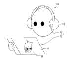
另外,通过将上述PDLC面板10与作为光源装置4的小型的投影仪3组合,能够合适地用于例如便携式电话等便携式终端。In addition, by combining the above-mentioned
[实施方式2][Embodiment 2]
基于图27(a)、(b)~图29对本发明的其他实施方式进行说明如下。Another embodiment of the present invention will be described below based on FIGS. 27( a ), ( b ) to FIG. 29 .
另外,为了说明的方便,对具有与用实施方式1说明过的附图相同功能的构成要素标注相同的编号,省略其说明。In addition, for the sake of convenience of description, the components having the same functions as those in the drawings described in the first embodiment are given the same reference numerals, and the description thereof will be omitted.
在本实施方式中,参照图27(a)、(b)和图28对将实施方式1所述的显示系统1用于便携式电话等便携式终端的例子在以下进行说明。In this embodiment, an example in which the
另外,在本实施方式中,作为便携式终端的一例,对将上述显示系统1用于便携式电话的例子进行说明。In addition, in this embodiment, an example in which the above-mentioned
图27(a)、(b)分别是表示本实施方式的便携式电话的概略结构的正面图,图28是表示图27所示的便携式电话的概略结构的背面立体图。27( a ) and ( b ) are front views showing the schematic structure of the mobile phone according to this embodiment, respectively, and FIG. 28 is a rear perspective view showing the general structure of the mobile phone shown in FIG. 27 .
如图27(a)、(b)所示,本实施方式的便携式电话90,如图27(a)、(b)和图28所示,由装置主体94构成,该装置主体94包括:用于在显示面92显示图像、时间或电话号码等用户视听的视频的显示部91;和用于接收用于将视频显示在作为电话的操作和显示部91的操作的操作键101(操作部)。As shown in Fig. 27(a), (b), the
在上述显示部91,作为显示装置和显示面板,使用实施方式1所述的显示装置2和PDLC面板10,另外,在装置主体94,如图28所示,具有作为用于从显示部91的背面93一侧照射光的光源装置(即,图5(a)、(b)等所示的光源装置4)的小型投影仪95。In the above-mentioned
即,上述便携式电话90,在装置主体94内置有小型投影仪95,从显示部91的显示面板附近的后方向显示部91的背面93输出光(视频)。That is, the
另外,在上述便携式电话90的装置主体94内部,设置有校正成能够从上述开口窗96将没有失真的视频映出到显示部91所用的显示面板(即,PDLC面板10)的背面93的透镜(例如非球面凹面反射镜)。In addition, inside the device
接着,参照图29对利用上述小型投影仪95进行的向显示部91的视频照射在以下进行说明。Next, video irradiation to the
图29是表示图27(a)、(b)和图28所示的便携式电话90的概略结构的截面图。FIG. 29 is a cross-sectional view showing a schematic structure of the
上述小型投影仪95,如图29所示,具有:用于将由光调制部形成的视频输出的视频输出部97;和用于将从视频输出部97输出的视频放大的投影透镜98。The
上述小型投影仪95的光调制部,使用例如使用激光的光调制部和使用DMD(Digital Micro-Mirror Device:注册商标)和液晶的光调制部。As the light modulation unit of the above-mentioned
在图29中,将从小型投影仪95的投影透镜98投射的光用虚线箭头表示。In FIG. 29 , the light projected from the
即,从小型投影仪95的视频输出部97投射的光,被设置在装置主体94内的非球面凹面反射镜99的反射面100反射,通过设置在装置主体94的上表面的开口窗96,投影到显示部91的背面93。另外,图29所示的虚线箭头,为了便于说明,简易地表示,并不严密地表现成像前的光等。That is, the light projected from the
在上述便携式电话90中,在进行彩色显示时,在实施方式1所述的方法中,可以使显示部91和小型投影仪95的视频同步。In the
在上述便携式电话90中,在彩色显示时,由于颜色表现由小型投影仪95进行,所以能够提高构成显示部91的PDLC面板10的透过率。In the
另外,如果利用小型投影仪95进行精细度高的显示,则能够降低构成显示部91的PDLC面板10的分辨率,因此,能够进一步提高PDLC面板10的透过率。因此,在上述便携式电话90中,也能够在进行散射/透明显示时,进行透明度高的透明显示。In addition, if high-definition display is performed by the
另外,在显示部91不进行彩色显示而进行散射/透明显示时,只要不进行装置主体94内的小型投影仪95的输出,而在PDLC面板10施加电压形成透明部12和散射部13,由此进行利用散射部13的图像显示(散射显示)即可。在这种情况下,由于能够削减小型投影仪95的输出所使用的电力,能够以低消耗电力进行显示。In addition, when the
另外,在如上所述在显示部91使用PDLC面板10进行彩色显示的情况下,如上所述,由于PDLC面板10的前方散射强,所以能够在显示部91的显示面92得到鲜明的显示,但由于后方散射弱,所以在显示部91的背面93显示暗且反转后的视频。因此,便携式电话90的显示,成为他人难以从背面93识别的显示。In addition, in the case of performing color display using the
另外,在便携式电话90等小型装置中通过使面板面弯曲,能够提高设计性。In addition, in a small device such as the
[实施方式3][Embodiment 3]
基于图30对本发明的其他实施方式进行说明如下。Another embodiment of the present invention will be described below based on FIG. 30 .
另外,为了便于说明,具有与用实施方式1、2说明过的附图相同功能的构成要素标注相同编号,省略其说明。In addition, for convenience of description, components having the same functions as those in the drawings described in
在上述实施方式1、2中,作为使用本发明的显示系统1的电子设备(特别是便携型的电子设备或能够携带的电子设备),主要对电子相框80、便携式电话90或电子词典等具有显示装置2(PDLC面板10)和投影仪3组合到一个装置内的结构的电子设备进行说明。In
在本实施方式中,参照图30对将显示系统1用于作为便携型的电子设备的PDLC面板10和投影仪3分离的分离型的电子设备的情况在以下进行说明。In this embodiment, a case where the
图30是示意性地表示本实施方式的显示系统所用的电子设备的一例的图。FIG. 30 is a diagram schematically showing an example of electronic equipment used in the display system of this embodiment.
本实施方式的电子设备,作为具有PDLC面板10的显示装置2和投影仪3独立地单独的设备使用,表示在耳机110(设备、形态终端、电子设备)的扬声部器111设置有作为光源装置4的投影仪3的例子。The electronic device of this embodiment is used as a separate device with the
在图30所示的显示系统1中,用户手持显示装置2,通过设置在耳机110的扬声器部111的投影仪3,在显示装置2的PDLC面板10投射视频。In the
在这种情况下,设置在耳机110的扬声器部111的投影仪3和显示装置2,可以用无线、有线的任何方法连接。在无线的情况下,可以考虑例如像Bluetooth(注册商标)那样利用电波的方式,或像IrDA(注册商标)那样的利用红外线的方式。In this case, the
另外,投影仪3除了设置在耳机110的扬声器部111以外,虽然未图示,也可以以挂在眼镜、头颈的状态保持。In addition, the
而且,投影仪3可以设置于设备,也可以设置于计算机、桌子等。在这种情况下,需要将投影仪3配置成能够对用户手持的显示装置2适当地投射视频。Furthermore, the
在图30所示的显示系统1中,显示装置2的图像与投影仪3的图像的位置对齐的方法,能够用与上述实施方式1说明过的方法相同的方法进行。In the
例如,可以如实施方式1中用图14说明过的那样,在PDLC面板10的显示区域16外设置回归反射板71,在投影仪3(光源装置4)设置具有受光元件和发光元件的传感器58,或者如用图15说明过的那样,在PDLC面板10的显示区域16外设置传感器58,在传感器3(光源装置4)设置回归反射板71,由此检测PDLC面板10相对于投影仪3(光源装置4)的位置信息,或者投影仪3(光源装置4)相对于PDLC面板10的位置信息。For example, as described with reference to FIG. 14 in
或者,也可以如用图16说明过的那样,在PDLC面板10的显示区域16内,设置具有受光元件的传感器59(像素内传感器),由此检测PDLC面板10相对于投影仪3(光源装置4)的位置信息。Alternatively, as described in FIG. 16 , a sensor 59 (in-pixel sensor) having a light receiving element may be provided in the
另外,位置信息的检测方法,可以是三角测量方式,也可以是使用激光光源的相位差测距方式。In addition, the detection method of the position information may be a triangulation method, or a phase difference distance measurement method using a laser light source.
这种图像的位置对齐,优选想要在操作显示装置2或投影仪3进行显示时,在从投影仪3进行光的输出前进行。如果在进行位置对齐前从投影仪3输出光,则有可能使他人或自己晃眼。Such alignment of images is preferably performed before light is output from the
另外,在这种分离型的电子设备中,面板位置不固定的情况较多,所以位置对齐优选经常或定期地进行。In addition, in such separate electronic devices, the position of the panel is often not fixed, so it is preferable to perform alignment frequently or periodically.
像这样,通过使显示部(PDLC面板10)和光源装置4的距离拉开,能够不使用复杂的光学系统地,从光源装置4照射均匀的明亮度的光到PDLC面板10的显示区域16整个面,并且能够得到能够使装置的重量负担分散的效果。Thus, by increasing the distance between the display unit (PDLC panel 10) and the
另外,在本实施方式中,以使用在聚合物中液晶呈液滴状分散的PDLC作为上述显示介质的情况为例进行了说明,但是,作为上述显示介质,也可以使用通过控制有无电场的施加来有选择地形成光透过区域和光散射区域的显示介质,也可以仅限定于PDLC。In addition, in this embodiment, the case where PDLC in which liquid crystals are dispersed in a polymer in droplet form is used as the above-mentioned display medium has been described as an example. However, as the above-mentioned display medium, it is also possible to use The display medium applied to selectively form the light-transmitting region and the light-scattering region may be limited to PDLC only.
作为上述显示介质,可以是在液晶的连续相中含有网眼状的聚合物,根据有无电场的施加来切换光透过状态和光分散状态的PNLC(Polymer Network Liquid Crystal:聚合物网络型液晶)。As the above-mentioned display medium, there may be PNLC (Polymer Network Liquid Crystal: Polymer Network Liquid Crystal) that contains a mesh-like polymer in the continuous phase of liquid crystal, and switches the light transmission state and light dispersion state according to the application of an electric field.
即,在上述显示介质中,PDLC层40的液晶滴,可以作为与相邻的液滴隔离的独立体(单体)存在,也可以作为与相邻的液滴连接的连续体存在。That is, in the above-mentioned display medium, the liquid crystal droplets of the
本发明的显示面板,如上所述,具有如下结构:上述显示面板在具有配线的第一基板和与上述第一基板相对配置的第二基板之间具有显示介质,该显示介质根据有无电场的施加来切换光透过状态和光散射状态,上述显示面板不具有着色层,且通过控制对上述显示介质有无电场的施加来有选择地形成光透过区域和光散射区域,并且从观察者观看时在比上述配线靠近跟前的位置设置有使由上述配线导致的外部光的直接反射降低的反射率降低层、覆盖上述配线的遮光层和上述显示介质中的至少一个。The display panel of the present invention has a structure as described above: the display panel has a display medium between a first substrate having wiring and a second substrate opposite to the first substrate. The light-transmitting state and the light-scattering state are switched by the application of the above-mentioned display panel. The above-mentioned display panel does not have a colored layer, and the light-transmitting region and the light-scattering region are selectively formed by controlling the application of an electric field to the above-mentioned display medium, and viewed from the observer At least one of a reflectance reducing layer for reducing direct reflection of external light by the wiring, a light-shielding layer covering the wiring, and the display medium is provided in front of the wiring.
优选上述显示面板在上述第一基板和第二基板中的至少一个基板的表面形成有反射防止膜。In the display panel, an antireflection film is preferably formed on a surface of at least one of the first substrate and the second substrate.
另外,本发明的显示面板,如上所述,具有如下结构:上述显示面板在具有配线的第一基板和与上述第一基板相对配置的第二基板之间具有显示介质,该显示介质根据有无电场的施加来切换光透过状态和光散射状态,上述显示面板不具有着色层,且通过控制对上述显示介质有无电场的施加来有选择地形成光透过区域和光散射区域,并且在上述第一基板和第二基板中的至少一个基板的表面形成有反射防止膜。In addition, the display panel of the present invention has a structure as described above. The display panel has a display medium between a first substrate having wiring and a second substrate disposed opposite to the first substrate. There is no application of an electric field to switch the light transmission state and the light scattering state, the above-mentioned display panel does not have a colored layer, and the light transmission area and the light scattering area are selectively formed by controlling the application of an electric field to the above-mentioned display medium, and in the above-mentioned An anti-reflection film is formed on a surface of at least one of the first substrate and the second substrate.
根据本发明,如上所述,通过设置(1)从观察者观看时在比上述配线靠近跟前的位置设置的上述反射率降低层、上述遮光层、上述显示介质中的至少一个,或者(2)在上述第一基板和第二基板中的至少一个基板的表面设置的反射防止膜中的至少一个,能够得到上述光散射区域的图像浮出到空中的独特且有冲击力的显示。According to the present invention, as described above, by providing (1) at least one of the above-mentioned reflectance reducing layer, the above-mentioned light shielding layer, and the above-mentioned display medium provided at a position closer to the above-mentioned wiring when viewed from an observer, or (2) ) At least one of the anti-reflection films provided on the surface of at least one of the first substrate and the second substrate can obtain a unique and powerful display in which the image of the light scattering region floats into the air.
另外,根据本发明,通过具有上述(1)的结构,能够抑制来自配线的直接反射。另外,通过具有上述(2)的结构,能够抑制基板的表面反射。通过具有上述(1)和(2)的结构中的至少一个,如上所述,能够得到上述光散射区域的图像浮出到空中的显示,而通过具有上述(1)和(2)的结构两者,能够通过其协同效应,得到更显著的效果。In addition, according to the present invention, direct reflection from wiring can be suppressed by having the configuration of (1) above. Moreover, by having the structure of said (2), surface reflection of a board|substrate can be suppressed. By having at least one of the above-mentioned structures (1) and (2), as described above, it is possible to obtain a display in which the image of the above-mentioned light scattering region floats into the air, and by having both of the above-mentioned structures (1) and (2) Those who can obtain more significant effect through its synergistic effect.
在本发明中,优选上述第一基板是具有呈矩阵状形成的多个配线和开关元件的有源矩阵基板,通过利用上述开关元件控制对上述显示介质有无电场的施加来有选择地形成光透过区域和光散射区域。In the present invention, it is preferable that the first substrate is an active matrix substrate having a plurality of wirings and switching elements formed in a matrix, and is selectively formed by using the switching elements to control the application of an electric field to the display medium. Light-transmitting regions and light-scattering regions.
根据上述结构,能够形成期望的形状的光散射区域,能够进行高精细的期望的显示。According to the above-mentioned configuration, it is possible to form a light-scattering region of a desired shape, and to perform a high-definition desired display.
另外,本发明的显示系统,如上所述,包括:具有本发明的上述显示面板的显示装置;和将单色或多色的光投射到上述显示面板的光源装置。Also, the display system of the present invention includes, as described above: a display device having the display panel of the present invention; and a light source device that projects monochromatic or multicolor light onto the display panel.
在上述显示系统中,能够采用如下结构:上述光源装置仅对形成在上述显示面板的光散射区域投射光。In the above display system, a configuration may be employed in which the light source device projects light only to the light scattering region formed on the display panel.
上述显示面板,在上述光散射区域中,进行利用从上述光源装置投射的光的图像显示。因此,如上所述,上述光源装置通过仅对形成在上述显示面板的光散射区域投射光,能够进行很清楚的高精细的显示,并且能够降低消耗电力。The display panel performs image display using light projected from the light source device in the light scattering region. Therefore, as described above, the light source device can perform clear and high-definition display and reduce power consumption by projecting light only on the light scattering region formed on the display panel.
另外,优选上述光源装置从上述显示面板的背面投射上述光。In addition, it is preferable that the light source device projects the light from the rear surface of the display panel.
如上所述的显示面板处于光散射状态时,入射到面板开口部的光,基本上都为前方散射。因此,为了有效地利用来自光源装置的光,优选将光源装置相对于观察者设置于显示面板的后方(背面侧)。由此,能够得到光源光的利用效率高且很清楚的明亮的显示图像。When the above-mentioned display panel is in the light-scattering state, basically all the light incident on the opening of the panel is forward-scattered. Therefore, in order to effectively use the light from the light source device, it is preferable to install the light source device behind the display panel (back side) with respect to the observer. Accordingly, it is possible to obtain a clear and bright display image with high utilization efficiency of light from the light source.
优选从上述光源装置向上述显示面板的投射光的入射角度最大的角度为80度以下。Preferably, an angle at which an incident angle of projected light from the light source device to the display panel is the largest is 80 degrees or less.
当从上述光源装置向远离上述显示面板的一侧,即从上述光源装置向显示装置入射的入射角度最大的角度超过80度时,透过率急剧降低,从上述光源装置投射的光,不会有效地入射到上述显示面板内。但是,如果上述入射角最大的角度为80度,则能够得到约60%的透过率。When the angle from the light source device to the side away from the display panel, that is, the maximum incident angle from the light source device to the display device exceeds 80 degrees, the transmittance decreases sharply, and the light projected from the light source device will not Effectively incident into the above-mentioned display panel. However, if the maximum incident angle is 80 degrees, a transmittance of about 60% can be obtained.
因此,通过使上述入射角最大的角度为80度以下,能够得到透过率高且没有明亮度不均的显示。Therefore, by setting the angle at which the above incident angle is the largest to 80 degrees or less, a display with high transmittance and no brightness unevenness can be obtained.
另外,如果将与入射面平行的偏振成分(S偏振光)也一起考虑,则直到布鲁斯特角为止,对于上述入射角度最大的角度,透过率没有大的变化,但当超过布鲁斯特角时,反射率急剧上升,从光源装置入射到上述显示面板的光减少。In addition, if the polarization component parallel to the incident plane (S polarized light) is also considered, the transmittance does not change significantly for the above-mentioned angle with the largest incident angle up to the Brewster angle, but when the Brewster angle is exceeded , the reflectance increases sharply, and the light incident on the display panel from the light source device decreases.
因此,优选上述入射角最大的角度为布鲁斯特角以下。Therefore, it is preferable that the angle at which the above-mentioned incident angle is the largest is equal to or less than Brewster's angle.
另外,优选:在上述显示系统中,上述显示介质是含有聚合物和独立或连续的液晶滴,且施加电场时成为光透过状态,无施加电场时成为光散射状态的高分子分散型或聚合物网络型液晶,上述第一基板和第二基板的与上述显示介质相对的面实施过取向处理,上述液晶滴沿着上述第一基板和第二基板的取向处理方向与基板面平行地排列,并且上述光源装置配置成:在将从上述光源装置投射的光平面投影到上述显示面板上时,从上述光源装置投射的光入射到上述显示面板的方向与液晶滴的排列方向垂直。In addition, it is preferable that in the above-mentioned display system, the above-mentioned display medium is a polymer-dispersed or aggregated polymer that contains a polymer and independent or continuous liquid crystal droplets, and is in a light-transmitting state when an electric field is applied, and in a light-scattering state when an electric field is not applied. In the IoT-type liquid crystal, the surfaces of the first substrate and the second substrate opposite to the display medium have been subjected to orientation treatment, and the liquid crystal droplets are arranged parallel to the substrate surface along the orientation treatment direction of the first substrate and the second substrate, In addition, the light source device is arranged such that when the light projected from the light source device is projected onto the display panel, the direction in which the light projected from the light source device is incident on the display panel is perpendicular to the arrangement direction of the liquid crystal droplets.
上述显示面板,在处于光散射状态时,从面板法线方向入射的光的散射光的强度,从面板法线方向看时在与液晶滴的排列方向垂直的方向上强烈地散射。When the above-mentioned display panel is in the light scattering state, the intensity of scattered light of light incident from the panel normal direction is strongly scattered in a direction perpendicular to the alignment direction of liquid crystal droplets when viewed from the panel normal direction.
因此,通过如上所述配置光源装置,能够使入射到上述显示面板的来自光源装置的光有效地散射,到达观察者。Therefore, by arranging the light source device as described above, the light from the light source device incident on the display panel can be efficiently diffused to reach the observer.
另外,优选:在上述显示系统中,上述显示介质是含有聚合物和独立或连续的液晶滴,且施加电场时成为光散射状态,无施加电场时成为光透过状态的高分子分散型或聚合物网络型液晶,上述第一基板和第二基板的与上述显示介质相对的面实施过取向处理,上述液晶滴的液晶分子的长轴沿着上述第一基板和第二基板的取向处理方向与基板面平行地排列,并且上述光源装置配置成:在将从上述光源装置投射的光平面投影在上述显示面板上时,从上述光源装置投射的光入射到上述显示面板的方向与上述液晶分子的长轴垂直。In addition, it is preferable that in the above-mentioned display system, the above-mentioned display medium is a polymer-dispersed or aggregated polymer that contains a polymer and independent or continuous liquid crystal droplets, and is in a light-scattering state when an electric field is applied, and in a light-transmitting state when an electric field is not applied. In the matter network type liquid crystal, the surfaces of the above-mentioned first substrate and the second substrate opposite to the above-mentioned display medium have been subjected to orientation treatment, and the long axes of the liquid crystal molecules of the above-mentioned liquid crystal droplets are along the direction of the orientation treatment of the above-mentioned first substrate and the second substrate. The substrate surfaces are arranged in parallel, and the light source device is arranged such that when the light projected from the light source device is projected onto the display panel, the direction in which the light projected from the light source device enters the display panel is in the same direction as the direction of the liquid crystal molecules. The long axis is vertical.
上述显示面板,在处于光散射状态时,从面板法线方向入射的光的散射光的强度,从面板法线方向看时在与液晶分子的长轴垂直的方向上强地散射。When the above-mentioned display panel is in the light scattering state, the intensity of scattered light of light incident from the panel normal direction is strongly scattered in a direction perpendicular to the long axis of the liquid crystal molecules when viewed from the panel normal direction.
因此,通过如上所述配置光源装置,能够使入射到上述显示面板的来自光源装置的光有效地散射,到达观察者。Therefore, by arranging the light source device as described above, the light from the light source device incident on the display panel can be efficiently diffused to reach the observer.
优选上述显示系统仅在进行彩色显示时从上述光源装置将光投射到上述显示面板,在进行非彩色显示时不从上述光源装置投射光,有选择地向上述显示介质施加电场而有选择地使该显示介质成为光散射状态和光透过状态,由此进行显示。Preferably, the display system projects light from the light source device to the display panel only when performing color display, and selectively applies an electric field to the display medium while performing achromatic display without projecting light from the light source device. The display medium is in a light-scattering state and a light-transmitting state, thereby performing display.
根据上述结构,彩色显示时能够进行设计性优秀的显示,而在文本显示等不需要彩色显示的情况下,通过仅驱动上述显示面板进行非彩色的光散射/光透过显示,能够停止光源装置的输出,所以能够进行低消耗电力的显示。According to the above-mentioned structure, it is possible to perform a display with excellent design in color display, and when a color display is unnecessary such as text display, the light source device can be stopped by only driving the above-mentioned display panel to perform achromatic light-scattering/light-transmitting display. output, it is possible to display with low power consumption.
优选上述显示面板从观察者观看时在进深方向上排列有多个。It is preferable that a plurality of the above-mentioned display panels are arranged in a depth direction when viewed by an observer.
根据上述结构,能够进行有效利用了进深的立体的显示(表现)。According to the above configuration, it is possible to perform a three-dimensional display (representation) that effectively utilizes depth.
另外,优选如上所述显示面板从观察者观看时在进深方向上排列有多个的情况下,上述显示面板中,从观察者观看时越设置在里侧的显示面板越大。In addition, when a plurality of display panels are arranged in the depth direction when viewed from an observer, it is preferable that among the display panels, the display panels arranged on the rear side are larger when viewed from an observer.
根据上述结构,能够得到更自然的进深感。According to the above configuration, a more natural sense of depth can be obtained.
优选上述显示面板具有弯曲的面板面。Preferably, the display panel has a curved panel surface.
在这种情况下,例如通过使面板面向观察者弯曲成凸形状,能够对来自各个角度的观察提高表现力。另外,通过使向观察者弯曲成凹形状,能够进行临场感高的显示。In this case, for example, by bending the panel in a convex shape facing the viewer, expressiveness can be improved for observation from various angles. In addition, display with a high sense of presence can be performed by bending the display in a concave shape toward the viewer.
另外,优选上述光源装置设置有多个,各光源装置各自的投射光的颜色不同。In addition, it is preferable that a plurality of the above-mentioned light source devices are provided, and the colors of the projected light of each light source device are different.
根据上述结构,能够在上述显示面板进行从各光源装置投射的投射光的按每个投射区域颜色不同的色彩丰富的显示,并且利用从各光源装置投射的投射光的重叠,能够进行进一步不同的颜色的显示。According to the above-mentioned configuration, it is possible to perform a colorful display on the display panel in which the projection light projected from each light source device is different in color for each projection area, and further different displays can be performed by superimposing the projection light projected from each light source device. Color display.
另外,优选上述光源装置具有灰度等级连续变化的滤光片。In addition, it is preferable that the light source device has an optical filter that continuously changes the gradation level.
根据上述结构,能够进行没有明亮度不均的均匀的显示。According to the above configuration, uniform display without brightness unevenness can be performed.
另外,本发明的电子设备,如上所述,具有本发明的上述显示系统。作为上述电子设备,除了能够作为便携式电话、电子词典、电子相框等便携式终端使用的电子设备以外,还可以列举数字标牌、影院系统、办公室用显示器、TV(电视)会议系统等各种电子设备。In addition, the electronic device of the present invention has the above-mentioned display system of the present invention as described above. Examples of the above-mentioned electronic devices include electronic devices that can be used as portable terminals such as mobile phones, electronic dictionaries, and electronic photo frames, as well as various electronic devices such as digital signage, theater systems, office displays, and TV (television) conference systems.
另外,本发明的便携式终端,如上所述,具有本发明的上述显示系统。In addition, the mobile terminal of the present invention includes the display system of the present invention as described above.
在上述便携式终端中,优选上述显示系统中的显示装置和光源装置作为独立的单独的设备设置。In the above-mentioned portable terminal, it is preferable that the display device and the light source device in the above-mentioned display system are provided as independent individual devices.
根据上述结构,通过上述显示装置和光源装置作为独立的单独的设备设置,能够使上述便携式终端的各装置的重量负担分散。另外,通过使上述光源装置和上述显示装置的显示面板的距离拉开,能够不使用复杂的光学系统地,从上述光源装置在上述显示面板的显示区域整个面照射均匀的明亮度的光。According to the above configuration, since the display device and the light source device are provided as independent individual devices, it is possible to distribute the weight burden of each device of the mobile terminal. In addition, by increasing the distance between the light source device and the display panel of the display device, the entire display area of the display panel can be irradiated with light of uniform brightness from the light source device without using a complicated optical system.
本发明并不限定于上述的各实施方式,能够在权利要求所示的范围内进行各种变更,将在各种实施方式中分别公开的技术手段适当组合而得到的实施方式也包含在本发明的技术范围内。The present invention is not limited to the above-mentioned embodiments, and various changes can be made within the scope shown in the claims. Embodiments obtained by appropriately combining the technical means disclosed in the various embodiments are also included in the present invention. within the technical range.
产业上的利用可能性Industrial Utilization Possibility
本发明的显示面板和显示系统,能够以高面板透过率实现透明状态(透视状态),并且能够得到像浮出到空中的显示。因此,能够合适地用于便携式电话或电子词典等便携式终端、电子相框、数字标牌、影院系统、办公室用显示器、TV会议系统等各种电子设备。The display panel and the display system of the present invention can realize a transparent state (see-through state) with a high panel transmittance, and can obtain a display in which an image appears floating in the air. Therefore, it can be suitably used for various electronic devices such as portable terminals such as mobile phones and electronic dictionaries, electronic photo frames, digital signage, theater systems, office monitors, and TV conference systems.
附图标记说明Explanation of reference signs
1 显示系统1 display system
2 显示装置2 display device
3 投影仪(光源装置)3 projector (light source device)
4 光源装置4 Light source device
5 ND滤镜5 ND filter
6 电路基板6 circuit substrate
10 PDLC面板(显示面板)10 PDLC panel (display panel)
11 像素11 pixels
12 透明部12 transparent part
13 散射部13 Scattering part
14 反射防止膜14 anti-reflection film
16 显示区域16 display area
20 基板(有源矩阵基板、第一基板)20 substrate (active matrix substrate, first substrate)
21 透明基板21 transparent substrate
22 TFT(开关元件)22 TFT (switching element)
23 像素电极23 pixel electrodes
24 源极配线(配线)24 Source wiring (wiring)
25 栅极配线(配线)25 Gate wiring (wiring)
26 Cs配线(配线)26 Cs wiring (wiring)
27 配线反射率降低层(反射率降低层)27 Wiring reflectance reduction layer (reflectance reduction layer)
30 基板(对置基板、第二基板)30 substrates (counter substrate, second substrate)
31 透明基板31 transparent substrate
32 黑矩阵(遮光膜)32 black matrix (shading film)
33 对置电极33 Counter electrode
40 PDLC层(显示介质层)40 PDLC layer (display medium layer)
41 液晶滴41 Liquid crystal drops
42 排列方向(液晶滴的排列方向)42 Arrangement direction (arrangement direction of liquid crystal drops)
43 入射方向(从光源装置投射的光向显示面板入射的方向)43 Incident direction (the direction in which the light projected from the light source device is incident on the display panel)
44 长轴(液晶分子的长轴)44 Long axis (long axis of liquid crystal molecules)
51 数据接收部51 Data Receiving Department
52 数据接收控制部52 Data reception control department
53 运算控制部53 Computing Control Department
54 视频控制部54 Video Control Department
55 存储部55 storage department
56 操作部56 Operation Department
57 位置信息取得部57 Location Information Acquisition Department
58 传感器58 sensors
59 传感器59 sensors
61 显示控制电路61 Display control circuit
62 面板显示控制电路62 panel display control circuit
63 光源显示控制电路63 Light source display control circuit
64 反馈电路64 feedback circuit
71 回归反射板71 retroreflective sheet
72 传感器用光源72 Light source for sensor
80 电子相框(电子部件)80 electronic photo frame (electronic components)
90 便携式电话(便携式终端、电子部件)90 Portable telephones (portable terminals, electronic components)
91 显示部91 display unit
92 显示面92 display surface
93 背面93 back
94 装置主体94 Device main body
95 小型投影仪(光源装置)95 small projector (light source device)
96 开口窗96 opening window
97 视频输出部97 Video output unit
98 投影透镜98 projection lens
99 非球面凹面反射镜99 aspheric concave mirror
100 反射面100 reflective surface
101 操作键101 Operation keys
110 耳机(设备、形态终端、电子设备)110 Earphones (equipment, modality terminal, electronic equipment)
111 扬声器部(电子部件)111 Speaker Department (Electronic Components)
Claims (20)
Translated fromChineseApplications Claiming Priority (3)
| Application Number | Priority Date | Filing Date | Title |
|---|---|---|---|
| JP2009235738 | 2009-10-09 | ||
| JP2009-235738 | 2009-10-09 | ||
| PCT/JP2010/058814WO2011043100A1 (en) | 2009-10-09 | 2010-05-25 | Display panel, display system, portable terminal and electronic device |
Publications (2)
| Publication Number | Publication Date |
|---|---|
| CN102483530Atrue CN102483530A (en) | 2012-05-30 |
| CN102483530B CN102483530B (en) | 2015-02-11 |
Family
ID=43856580
Family Applications (1)
| Application Number | Title | Priority Date | Filing Date |
|---|---|---|---|
| CN201080037317.2AExpired - Fee RelatedCN102483530B (en) | 2009-10-09 | 2010-05-25 | Display panel, display system, portable terminal and electronic device |
Country Status (3)
| Country | Link |
|---|---|
| US (1) | US20120140147A1 (en) |
| CN (1) | CN102483530B (en) |
| WO (1) | WO2011043100A1 (en) |
Cited By (16)
| Publication number | Priority date | Publication date | Assignee | Title |
|---|---|---|---|---|
| CN103543550A (en)* | 2012-07-12 | 2014-01-29 | 精工爱普生株式会社 | Screen and image display system |
| CN103680323A (en)* | 2013-12-13 | 2014-03-26 | 苏州市峰之火数码科技有限公司 | Reflection-type digital album |
| CN103792717A (en)* | 2012-10-31 | 2014-05-14 | 法国圣-戈班玻璃公司 | Variable light diffusion system comprising a PDLC layer |
| TWI458530B (en)* | 2012-08-20 | 2014-11-01 | Au Optronics Corp | Entertainment display system and interactive stereoscopic displaying method of same |
| CN104423131A (en)* | 2013-09-05 | 2015-03-18 | 联想(北京)有限公司 | Display device and display method |
| TWI483030B (en)* | 2014-06-06 | 2015-05-01 | Chunghwa Picture Tubes Ltd | Transparent display device and displaying method thereof |
| CN104781728A (en)* | 2012-11-13 | 2015-07-15 | 3M创新有限公司 | Switchable transparent display |
| CN105204215A (en)* | 2015-09-16 | 2015-12-30 | 上海玮舟微电子科技有限公司 | Multi-path power control system and method for PDLC (Polymer Dispersed Liquid Crystal) dimming films |
| CN105408809A (en)* | 2013-07-23 | 2016-03-16 | 3M创新有限公司 | Addressable switchable transparent display |
| CN106896561A (en)* | 2017-04-20 | 2017-06-27 | 信利半导体有限公司 | PDLC display panels and its manufacture method |
| CN107422532A (en)* | 2017-08-16 | 2017-12-01 | 京东方科技集团股份有限公司 | A kind of transparent display panel, its preparation method and display system |
| CN109061966A (en)* | 2018-08-15 | 2018-12-21 | 友达光电股份有限公司 | Display system |
| CN109479125A (en)* | 2016-07-14 | 2019-03-15 | 三星电子株式会社 | Projection system with enhanced color and contrast |
| CN109656089A (en)* | 2019-02-01 | 2019-04-19 | 腾讯科技(深圳)有限公司 | Display device and image display method |
| CN109656043A (en)* | 2019-02-01 | 2019-04-19 | 腾讯科技(深圳)有限公司 | Display device and image display method |
| CN115356878A (en)* | 2022-09-06 | 2022-11-18 | 厦门天马微电子有限公司 | Display panel and display device |
Families Citing this family (33)
| Publication number | Priority date | Publication date | Assignee | Title |
|---|---|---|---|---|
| US8686864B2 (en) | 2011-01-18 | 2014-04-01 | Marwan Hannon | Apparatus, system, and method for detecting the presence of an intoxicated driver and controlling the operation of a vehicle |
| US8718536B2 (en) | 2011-01-18 | 2014-05-06 | Marwan Hannon | Apparatus, system, and method for detecting the presence and controlling the operation of mobile devices within a vehicle |
| JP5866936B2 (en)* | 2011-09-30 | 2016-02-24 | セイコーエプソン株式会社 | Image display system |
| US9535313B2 (en) | 2012-09-14 | 2017-01-03 | Scienstry, Inc. | Underwater projection |
| EP2902843B1 (en)* | 2012-09-27 | 2018-12-26 | Mitsubishi Chemical Corporation | Image display device |
| FR2997516B1 (en)* | 2012-10-31 | 2015-11-13 | Saint Gobain | GLAZING COMPRISING A VARIABLE LIGHT DISTRIBUTION SYSTEM AND A PAIR OF ABSORBENT ELEMENTS |
| JP6175800B2 (en)* | 2013-02-26 | 2017-08-09 | 株式会社ニコン | Screen and projection system |
| US9113036B2 (en)* | 2013-07-17 | 2015-08-18 | Ebay Inc. | Methods, systems, and apparatus for providing video communications |
| KR102315659B1 (en)* | 2013-11-27 | 2021-10-20 | 가부시키가이샤 한도오따이 에네루기 켄큐쇼 | Display device |
| US10380933B2 (en) | 2014-02-07 | 2019-08-13 | Samsung Electronics Company, Ltd. | Display with high transparency |
| US10554962B2 (en) | 2014-02-07 | 2020-02-04 | Samsung Electronics Co., Ltd. | Multi-layer high transparency display for light field generation |
| US10375365B2 (en)* | 2014-02-07 | 2019-08-06 | Samsung Electronics Co., Ltd. | Projection system with enhanced color and contrast |
| US10453371B2 (en) | 2014-02-07 | 2019-10-22 | Samsung Electronics Co., Ltd. | Multi-layer display with color and contrast enhancement |
| US10565925B2 (en) | 2014-02-07 | 2020-02-18 | Samsung Electronics Co., Ltd. | Full color display with intrinsic transparency |
| WO2015132983A1 (en)* | 2014-03-06 | 2015-09-11 | シャープ株式会社 | Image display device |
| WO2015190588A1 (en) | 2014-06-13 | 2015-12-17 | シャープ株式会社 | Liquid crystal display device |
| WO2015190461A1 (en) | 2014-06-13 | 2015-12-17 | シャープ株式会社 | Display device |
| FR3023930A1 (en)* | 2014-07-17 | 2016-01-22 | Commissariat Energie Atomique | SCREEN AND DISPLAY DEVICE IN RETROPROJECTION |
| JP5998361B2 (en)* | 2014-09-01 | 2016-09-28 | パナソニックIpマネジメント株式会社 | Video projection system |
| US10048538B1 (en)* | 2014-10-08 | 2018-08-14 | Sharp Kabushiki Kaisha | Display device |
| JP6606634B2 (en)* | 2015-02-02 | 2019-11-20 | 日本精機株式会社 | Projection apparatus, control method, program, and storage medium |
| EP4083696B1 (en)* | 2015-06-30 | 2025-08-06 | Gauzy Ltd. | Advanced polymer dispersed liquid crystal (pdlc) for a display projection screens |
| US10205819B2 (en) | 2015-07-14 | 2019-02-12 | Driving Management Systems, Inc. | Detecting the location of a phone using RF wireless and ultrasonic signals |
| CN104991413A (en)* | 2015-07-22 | 2015-10-21 | 明基材料有限公司 | Projection system |
| KR102390991B1 (en)* | 2015-09-30 | 2022-04-27 | 삼성디스플레이 주식회사 | Display device and fabricating method of the same |
| EP3469576B1 (en)* | 2016-07-14 | 2024-07-03 | Samsung Electronics Co., Ltd. | Multi-layer display with color and contrast enhancement |
| JP6451793B2 (en)* | 2017-07-13 | 2019-01-16 | 株式会社ニコン | Screen and projection system |
| US10955603B2 (en)* | 2017-10-17 | 2021-03-23 | Synaptics Incorporated | Method and system for optical imaging using point source illumination |
| US10104210B1 (en)* | 2018-01-31 | 2018-10-16 | Yonatan Zike Zenebe | Projector housing for iPhone |
| JP2020077484A (en)* | 2018-11-06 | 2020-05-21 | 凸版印刷株式会社 | Dimming system |
| CN112445007A (en)* | 2020-12-11 | 2021-03-05 | 体验科技股份有限公司 | Display body screen device, display method and projection system |
| JP2024016623A (en) | 2022-07-26 | 2024-02-07 | トヨタ自動車株式会社 | Image transmission system, image transmission method |
| DE102023105014A1 (en)* | 2023-03-01 | 2024-09-05 | Dr. Ing. H.C. F. Porsche Aktiengesellschaft | Arrangement for the visual presentation of information in the area of a windscreen of a motor vehicle |
Citations (7)
| Publication number | Priority date | Publication date | Assignee | Title |
|---|---|---|---|---|
| CN1179552A (en)* | 1996-09-25 | 1998-04-22 | 松下电器产业株式会社 | High-molecular dispersed liquid crystal display element and its manufacturing method and apparatus using such method |
| JPH11218844A (en)* | 1998-02-02 | 1999-08-10 | Harness Syst Tech Res Ltd | Display device |
| JPH11337926A (en)* | 1998-05-26 | 1999-12-10 | Casio Comput Co Ltd | Liquid crystal display |
| US20020126396A1 (en)* | 1996-08-16 | 2002-09-12 | Eugene Dolgoff | Three-dimensional display system |
| US6590548B1 (en)* | 1998-02-09 | 2003-07-08 | Denso Corporation | Display apparatus and an image input apparatus used for the same |
| CN1550824A (en)* | 2003-05-06 | 2004-12-01 | ������������ʽ���� | Display device, display method and projector |
| US20050036084A1 (en)* | 2002-08-29 | 2005-02-17 | Hidenori Ishikawa | Projection type display apparatus |
Family Cites Families (8)
| Publication number | Priority date | Publication date | Assignee | Title |
|---|---|---|---|---|
| JPH05191726A (en)* | 1992-01-09 | 1993-07-30 | Nippon Telegr & Teleph Corp <Ntt> | Presence display device |
| KR970062775A (en)* | 1996-02-03 | 1997-09-12 | 구자홍 | Black matrix of liquid crystal display element and method of manufacturing the same |
| JPH11288035A (en)* | 1998-02-09 | 1999-10-19 | Denso Corp | Display |
| JPH11227926A (en)* | 1998-02-10 | 1999-08-24 | Shinko Electric Co Ltd | Drive control device of elliptic vibration parts feeder |
| JP2000075243A (en)* | 1998-08-31 | 2000-03-14 | Citizen Watch Co Ltd | Stereoscopic display device |
| JP4467686B2 (en)* | 1999-11-30 | 2010-05-26 | キヤノン株式会社 | Projection display |
| JP3941379B2 (en)* | 2000-11-02 | 2007-07-04 | セイコーエプソン株式会社 | Projection type 3D display device |
| KR100760938B1 (en)* | 2003-04-15 | 2007-09-21 | 엘지.필립스 엘시디 주식회사 | Reflective Liquid Crystal Display |
- 2010
- 2010-05-25USUS13/389,944patent/US20120140147A1/ennot_activeAbandoned
- 2010-05-25CNCN201080037317.2Apatent/CN102483530B/ennot_activeExpired - Fee Related
- 2010-05-25WOPCT/JP2010/058814patent/WO2011043100A1/enactiveApplication Filing
Patent Citations (7)
| Publication number | Priority date | Publication date | Assignee | Title |
|---|---|---|---|---|
| US20020126396A1 (en)* | 1996-08-16 | 2002-09-12 | Eugene Dolgoff | Three-dimensional display system |
| CN1179552A (en)* | 1996-09-25 | 1998-04-22 | 松下电器产业株式会社 | High-molecular dispersed liquid crystal display element and its manufacturing method and apparatus using such method |
| JPH11218844A (en)* | 1998-02-02 | 1999-08-10 | Harness Syst Tech Res Ltd | Display device |
| US6590548B1 (en)* | 1998-02-09 | 2003-07-08 | Denso Corporation | Display apparatus and an image input apparatus used for the same |
| JPH11337926A (en)* | 1998-05-26 | 1999-12-10 | Casio Comput Co Ltd | Liquid crystal display |
| US20050036084A1 (en)* | 2002-08-29 | 2005-02-17 | Hidenori Ishikawa | Projection type display apparatus |
| CN1550824A (en)* | 2003-05-06 | 2004-12-01 | ������������ʽ���� | Display device, display method and projector |
Cited By (20)
| Publication number | Priority date | Publication date | Assignee | Title |
|---|---|---|---|---|
| CN103543550A (en)* | 2012-07-12 | 2014-01-29 | 精工爱普生株式会社 | Screen and image display system |
| TWI458530B (en)* | 2012-08-20 | 2014-11-01 | Au Optronics Corp | Entertainment display system and interactive stereoscopic displaying method of same |
| CN103792717A (en)* | 2012-10-31 | 2014-05-14 | 法国圣-戈班玻璃公司 | Variable light diffusion system comprising a PDLC layer |
| CN104781728A (en)* | 2012-11-13 | 2015-07-15 | 3M创新有限公司 | Switchable transparent display |
| CN105408809A (en)* | 2013-07-23 | 2016-03-16 | 3M创新有限公司 | Addressable switchable transparent display |
| CN104423131A (en)* | 2013-09-05 | 2015-03-18 | 联想(北京)有限公司 | Display device and display method |
| CN104423131B (en)* | 2013-09-05 | 2017-01-25 | 联想(北京)有限公司 | Display device and display method |
| CN103680323A (en)* | 2013-12-13 | 2014-03-26 | 苏州市峰之火数码科技有限公司 | Reflection-type digital album |
| TWI483030B (en)* | 2014-06-06 | 2015-05-01 | Chunghwa Picture Tubes Ltd | Transparent display device and displaying method thereof |
| CN105204215A (en)* | 2015-09-16 | 2015-12-30 | 上海玮舟微电子科技有限公司 | Multi-path power control system and method for PDLC (Polymer Dispersed Liquid Crystal) dimming films |
| CN105204215B (en)* | 2015-09-16 | 2019-10-18 | 上海玮舟微电子科技有限公司 | A kind of PDLC light modulation film multiple power supplies control system and method |
| CN109479125A (en)* | 2016-07-14 | 2019-03-15 | 三星电子株式会社 | Projection system with enhanced color and contrast |
| CN106896561A (en)* | 2017-04-20 | 2017-06-27 | 信利半导体有限公司 | PDLC display panels and its manufacture method |
| CN107422532A (en)* | 2017-08-16 | 2017-12-01 | 京东方科技集团股份有限公司 | A kind of transparent display panel, its preparation method and display system |
| CN109061966A (en)* | 2018-08-15 | 2018-12-21 | 友达光电股份有限公司 | Display system |
| CN109061966B (en)* | 2018-08-15 | 2021-12-21 | 友达光电股份有限公司 | Display system |
| CN109656089A (en)* | 2019-02-01 | 2019-04-19 | 腾讯科技(深圳)有限公司 | Display device and image display method |
| CN109656043A (en)* | 2019-02-01 | 2019-04-19 | 腾讯科技(深圳)有限公司 | Display device and image display method |
| CN115356878A (en)* | 2022-09-06 | 2022-11-18 | 厦门天马微电子有限公司 | Display panel and display device |
| CN115356878B (en)* | 2022-09-06 | 2025-02-07 | 厦门天马微电子有限公司 | Display panel and display device |
Also Published As
| Publication number | Publication date |
|---|---|
| CN102483530B (en) | 2015-02-11 |
| US20120140147A1 (en) | 2012-06-07 |
| WO2011043100A1 (en) | 2011-04-14 |
Similar Documents
| Publication | Publication Date | Title |
|---|---|---|
| CN102483530B (en) | Display panel, display system, portable terminal and electronic device | |
| CN103376589B (en) | Display device | |
| CN106133587B (en) | Mirror display and electronic apparatus | |
| US9971190B2 (en) | Display device and electronic apparatus | |
| TWI463218B (en) | Display device | |
| TWI474080B (en) | Liquid crystal display device | |
| US7643107B2 (en) | Liquid crystal display apparatus | |
| CN106023909B (en) | Display device and its display methods | |
| WO2012060306A1 (en) | Display system, mobile terminal, and electronic equipment | |
| JP2016519324A (en) | Transparent autostereoscopic display | |
| CN101029981A (en) | Semi-transmissive liquid crystal display device and portable terminal device | |
| US20170363797A1 (en) | Transparent display with improved contrast and transmission | |
| CN101738736A (en) | Display device capable of being switched into two-dimensional and three-dimensional display modes and active scattering lens thereof | |
| US20130258213A1 (en) | Electronic Display Projection Assembly Having Substantially White Off State | |
| CN106560885A (en) | Transparent display device | |
| JP2015191053A (en) | liquid crystal display device | |
| US9241154B2 (en) | Liquid crystal display panel and display method compatible with 2D and 3D display mode | |
| KR20140113463A (en) | Liquid crystal display device and electronic apparatus provided therewith | |
| WO2019024574A1 (en) | Colour film substrate, display panel, backlight module, display device and display system | |
| US9599854B2 (en) | Liquid crystal display device and electronic apparatus | |
| JP2007127724A (en) | Liquid crystal display device | |
| CN211426960U (en) | Transparent display and display system | |
| CN102063007A (en) | Liquid crystal glasses, projection display system and control method thereof | |
| CN108780252A (en) | Display device | |
| CN108469684B (en) | Transparent display and display system |
Legal Events
| Date | Code | Title | Description |
|---|---|---|---|
| C06 | Publication | ||
| PB01 | Publication | ||
| C10 | Entry into substantive examination | ||
| SE01 | Entry into force of request for substantive examination | ||
| C14 | Grant of patent or utility model | ||
| GR01 | Patent grant | ||
| CF01 | Termination of patent right due to non-payment of annual fee | Granted publication date:20150211 Termination date:20200525 | |
| CF01 | Termination of patent right due to non-payment of annual fee |