CN102481197A - Stent Delivery System - Google Patents
Stent Delivery SystemDownload PDFInfo
- Publication number
- CN102481197A CN102481197ACN2010800339557ACN201080033955ACN102481197ACN 102481197 ACN102481197 ACN 102481197ACN 2010800339557 ACN2010800339557 ACN 2010800339557ACN 201080033955 ACN201080033955 ACN 201080033955ACN 102481197 ACN102481197 ACN 102481197A
- Authority
- CN
- China
- Prior art keywords
- stent
- bumper
- wire
- pusher
- disposed
- Prior art date
- Legal status (The legal status is an assumption and is not a legal conclusion. Google has not performed a legal analysis and makes no representation as to the accuracy of the status listed.)
- Pending
Links
Images


Classifications
- A—HUMAN NECESSITIES
- A61—MEDICAL OR VETERINARY SCIENCE; HYGIENE
- A61F—FILTERS IMPLANTABLE INTO BLOOD VESSELS; PROSTHESES; DEVICES PROVIDING PATENCY TO, OR PREVENTING COLLAPSING OF, TUBULAR STRUCTURES OF THE BODY, e.g. STENTS; ORTHOPAEDIC, NURSING OR CONTRACEPTIVE DEVICES; FOMENTATION; TREATMENT OR PROTECTION OF EYES OR EARS; BANDAGES, DRESSINGS OR ABSORBENT PADS; FIRST-AID KITS
- A61F2/00—Filters implantable into blood vessels; Prostheses, i.e. artificial substitutes or replacements for parts of the body; Appliances for connecting them with the body; Devices providing patency to, or preventing collapsing of, tubular structures of the body, e.g. stents
- A61F2/95—Instruments specially adapted for placement or removal of stents or stent-grafts
- A61F2/962—Instruments specially adapted for placement or removal of stents or stent-grafts having an outer sleeve
- A61F2/966—Instruments specially adapted for placement or removal of stents or stent-grafts having an outer sleeve with relative longitudinal movement between outer sleeve and prosthesis, e.g. using a push rod
- A—HUMAN NECESSITIES
- A61—MEDICAL OR VETERINARY SCIENCE; HYGIENE
- A61F—FILTERS IMPLANTABLE INTO BLOOD VESSELS; PROSTHESES; DEVICES PROVIDING PATENCY TO, OR PREVENTING COLLAPSING OF, TUBULAR STRUCTURES OF THE BODY, e.g. STENTS; ORTHOPAEDIC, NURSING OR CONTRACEPTIVE DEVICES; FOMENTATION; TREATMENT OR PROTECTION OF EYES OR EARS; BANDAGES, DRESSINGS OR ABSORBENT PADS; FIRST-AID KITS
- A61F2/00—Filters implantable into blood vessels; Prostheses, i.e. artificial substitutes or replacements for parts of the body; Appliances for connecting them with the body; Devices providing patency to, or preventing collapsing of, tubular structures of the body, e.g. stents
- A61F2/82—Devices providing patency to, or preventing collapsing of, tubular structures of the body, e.g. stents
- A61F2/86—Stents in a form characterised by the wire-like elements; Stents in the form characterised by a net-like or mesh-like structure
- A61F2/90—Stents in a form characterised by the wire-like elements; Stents in the form characterised by a net-like or mesh-like structure characterised by a net-like or mesh-like structure
- A—HUMAN NECESSITIES
- A61—MEDICAL OR VETERINARY SCIENCE; HYGIENE
- A61F—FILTERS IMPLANTABLE INTO BLOOD VESSELS; PROSTHESES; DEVICES PROVIDING PATENCY TO, OR PREVENTING COLLAPSING OF, TUBULAR STRUCTURES OF THE BODY, e.g. STENTS; ORTHOPAEDIC, NURSING OR CONTRACEPTIVE DEVICES; FOMENTATION; TREATMENT OR PROTECTION OF EYES OR EARS; BANDAGES, DRESSINGS OR ABSORBENT PADS; FIRST-AID KITS
- A61F2/00—Filters implantable into blood vessels; Prostheses, i.e. artificial substitutes or replacements for parts of the body; Appliances for connecting them with the body; Devices providing patency to, or preventing collapsing of, tubular structures of the body, e.g. stents
- A61F2/82—Devices providing patency to, or preventing collapsing of, tubular structures of the body, e.g. stents
- A61F2002/823—Stents, different from stent-grafts, adapted to cover an aneurysm
- A—HUMAN NECESSITIES
- A61—MEDICAL OR VETERINARY SCIENCE; HYGIENE
- A61F—FILTERS IMPLANTABLE INTO BLOOD VESSELS; PROSTHESES; DEVICES PROVIDING PATENCY TO, OR PREVENTING COLLAPSING OF, TUBULAR STRUCTURES OF THE BODY, e.g. STENTS; ORTHOPAEDIC, NURSING OR CONTRACEPTIVE DEVICES; FOMENTATION; TREATMENT OR PROTECTION OF EYES OR EARS; BANDAGES, DRESSINGS OR ABSORBENT PADS; FIRST-AID KITS
- A61F2/00—Filters implantable into blood vessels; Prostheses, i.e. artificial substitutes or replacements for parts of the body; Appliances for connecting them with the body; Devices providing patency to, or preventing collapsing of, tubular structures of the body, e.g. stents
- A61F2/95—Instruments specially adapted for placement or removal of stents or stent-grafts
- A61F2002/9505—Instruments specially adapted for placement or removal of stents or stent-grafts having retaining means other than an outer sleeve, e.g. male-female connector between stent and instrument
- A—HUMAN NECESSITIES
- A61—MEDICAL OR VETERINARY SCIENCE; HYGIENE
- A61F—FILTERS IMPLANTABLE INTO BLOOD VESSELS; PROSTHESES; DEVICES PROVIDING PATENCY TO, OR PREVENTING COLLAPSING OF, TUBULAR STRUCTURES OF THE BODY, e.g. STENTS; ORTHOPAEDIC, NURSING OR CONTRACEPTIVE DEVICES; FOMENTATION; TREATMENT OR PROTECTION OF EYES OR EARS; BANDAGES, DRESSINGS OR ABSORBENT PADS; FIRST-AID KITS
- A61F2/00—Filters implantable into blood vessels; Prostheses, i.e. artificial substitutes or replacements for parts of the body; Appliances for connecting them with the body; Devices providing patency to, or preventing collapsing of, tubular structures of the body, e.g. stents
- A61F2/95—Instruments specially adapted for placement or removal of stents or stent-grafts
- A61F2002/9534—Instruments specially adapted for placement or removal of stents or stent-grafts for repositioning of stents
- A—HUMAN NECESSITIES
- A61—MEDICAL OR VETERINARY SCIENCE; HYGIENE
- A61F—FILTERS IMPLANTABLE INTO BLOOD VESSELS; PROSTHESES; DEVICES PROVIDING PATENCY TO, OR PREVENTING COLLAPSING OF, TUBULAR STRUCTURES OF THE BODY, e.g. STENTS; ORTHOPAEDIC, NURSING OR CONTRACEPTIVE DEVICES; FOMENTATION; TREATMENT OR PROTECTION OF EYES OR EARS; BANDAGES, DRESSINGS OR ABSORBENT PADS; FIRST-AID KITS
- A61F2/00—Filters implantable into blood vessels; Prostheses, i.e. artificial substitutes or replacements for parts of the body; Appliances for connecting them with the body; Devices providing patency to, or preventing collapsing of, tubular structures of the body, e.g. stents
- A61F2/95—Instruments specially adapted for placement or removal of stents or stent-grafts
- A61F2/962—Instruments specially adapted for placement or removal of stents or stent-grafts having an outer sleeve
- A61F2/966—Instruments specially adapted for placement or removal of stents or stent-grafts having an outer sleeve with relative longitudinal movement between outer sleeve and prosthesis, e.g. using a push rod
- A61F2002/9665—Instruments specially adapted for placement or removal of stents or stent-grafts having an outer sleeve with relative longitudinal movement between outer sleeve and prosthesis, e.g. using a push rod with additional retaining means
Landscapes
- Health & Medical Sciences (AREA)
- Engineering & Computer Science (AREA)
- Biomedical Technology (AREA)
- Cardiology (AREA)
- Oral & Maxillofacial Surgery (AREA)
- Transplantation (AREA)
- Heart & Thoracic Surgery (AREA)
- Vascular Medicine (AREA)
- Life Sciences & Earth Sciences (AREA)
- Animal Behavior & Ethology (AREA)
- General Health & Medical Sciences (AREA)
- Public Health (AREA)
- Veterinary Medicine (AREA)
- Media Introduction/Drainage Providing Device (AREA)
Abstract
Description
Translated fromChinese技术领域technical field
本发明的技术领域总体上涉及用于将支架传送到体腔中的装置。The technical field of the invention relates generally to devices for delivering stents into body lumens.
背景技术Background technique
支架、移植物、支架-移植物、腔静脉过滤器和类似的可移植的医疗装置(整体地在下文中称作支架)是径向地可扩张的支架,其通常是能够经腔地移植的并且在经皮引入以后能够径向地扩大的血管内的移植物。支架可以被移植到诸如在脉管系统、尿路、胆管等的多种体腔或者体管中。支架可以被用于加强体管并且防止在脉管系统中血管成形术以后的再狭窄。他们可以是自扩张的、机械地可扩张的或者混合动力(hybrid)可扩张的。Stents, grafts, stent-grafts, vena cava filters and similar implantable medical devices (collectively hereinafter referred to as stents) are radially expandable stents that are typically transluminally implantable and An intravascular graft capable of radial expansion after percutaneous introduction. Stents can be grafted into various body cavities or ducts, such as in the vasculature, urinary tract, bile ducts, and the like. Stents may be used to reinforce body vessels and prevent restenosis following angioplasty in the vasculature. They can be self-expanding, mechanically expandable, or hybrid (hybrid) expandable.
支架大致是用于插入到体腔中的管状装置。然而,应该注意的是,支架可以设置成多种尺寸和形状。球囊可扩张支架需要套装在球囊上、定位、并且使球囊膨胀以使该支架径向向外地扩张。当没有束缚时自扩张支架扩张就位,而不需要球囊的帮助。自扩张支架可能被偏压以便当从传送导管释放时扩张并且/或者包括形状记忆部件,形状记忆部件允许支架当暴露于预定情况中时扩张。一些支架的特征可以在于为混合动力支架,所述混合动力支架既具有可自扩张的又具有可球囊扩张支架的一些特征。A stent is generally a tubular device for insertion into a body cavity. It should be noted, however, that the brackets can be provided in a variety of sizes and shapes. Balloon-expandable stents require fitting over a balloon, positioning, and inflating the balloon to expand the stent radially outward. When untethered, the self-expanding stent expands into place without the aid of a balloon. Self-expanding stents may be biased to expand when released from the delivery catheter and/or include a shape memory component that allows the stent to expand when exposed to predetermined conditions. Some stents may be characterized as hybrid stents that share some of the features of both self-expandable and balloon-expandable stents.
支架可以由多种材料构造,诸如不锈钢、埃尔吉洛伊非磁性合金(Elgiloy)、镍、钛、镍钛诺、形状记忆聚合体等。支架也可以通过多种方式形成。例如,可以通过从支架材料的管材或片材来蚀刻或切割支架样式;支架材料的片材可以根据期望的支架样式来切割或者蚀刻,然后片材可以被卷起或者以其它方式形成为期望的大致管状的、分叉状的或者其它形状的支架;可以将支架材料的一个或多个丝线或者丝带纺织、编织或者通过其它方式来形成为期望的形状和样式。编织支架中的编织物密度以每英寸中的目数(pick)来测量。支架可以包括焊接、粘接或者其它的方式接合到彼此的部件。Stents can be constructed from a variety of materials such as stainless steel, Elgiloy, nickel, titanium, nitinol, shape memory polymers, and the like. Scaffolds can also be formed in a variety of ways. For example, the stent pattern can be etched or cut from a tube or sheet of stent material; the sheet of stent material can be cut or etched according to the desired stent pattern, and the sheet can then be rolled or otherwise formed into the desired Stents that are generally tubular, bifurcated, or otherwise shaped; one or more threads or ribbons of stent material can be woven, braided, or otherwise formed into the desired shape and pattern. Braid density in braided stents is measured in picks per inch. The bracket may include components that are welded, glued, or otherwise joined to each other.
自扩张支架通过所谓的“最小侵入技术”或者通过“切下”技术在狭窄或者动脉瘤的位置处植入到血管中或者其它体腔中,在所述“最小侵入技术”中,支架径向向内压缩并且通过导管穿过患者的皮肤传送到需要的位置处,在所述“切下”技术中,待处理的血管通过较小的外科装置而暴露。在这些技术中,微型导管穿过脉管系统直到其远端达到植入位置处。然后压缩支架被引入到微型导管的近端中并且利用推动器线而被推动穿过微型导管到达其远端。当支架被定位在正确的位置时,支架被推出微型导管(即,未加护套的),并且使得或者允许在血管中扩张到预定的直径。A self-expanding stent is implanted in a blood vessel or other body lumen at the site of a stenosis or aneurysm by the so-called "minimally invasive technique" in which the stent radially Compressed internally and delivered by a catheter through the patient's skin to the desired location, in the "cut-out" technique, the blood vessel to be treated is exposed through a smaller surgical device. In these techniques, a microcatheter is threaded through the vasculature until its distal end reaches the site of implantation. The compressed stent is then introduced into the proximal end of the microcatheter and pushed through the microcatheter to its distal end using a pusher wire. When the stent is positioned in the correct position, the stent is pushed out of the microcatheter (ie, unsheathed) and allowed or allowed to expand to a predetermined diameter within the vessel.
当前支架传送系统所认识到的问题包括不能使已经部分地(约50-80%)的未加护套的支架重新加护套。所认识到的问题还包括在推动器线的远端与支架的近端之间的联结处缺乏稳定性。另一所遇到的问题是单个编织线在编织支架的近端和远端处都趋于在支架被推动穿过微型导管时突然张开进入到微型导管壁中。此外,所认识到的问题包括在支架被推动穿过微型导管时支架在传送期间的径向扩张。最后两个认识到的问题增加了在支架被推动穿过微型导管时的摩擦阻力。A recognized problem with current stent delivery systems includes the inability to re-sheath unsheathed stents that have been partially (approximately 50-80%). Recognized problems also include lack of stability at the junction between the distal end of the pusher wire and the proximal end of the stent. Another problem encountered is that the individual braided wires at both the proximal and distal ends of the braided stent tend to flare up into the microcatheter wall as the stent is pushed through the microcatheter. Additionally, recognized issues include radial expansion of the stent during delivery as the stent is pushed through the microcatheter. The last two recognized problems increase the frictional resistance as the stent is pushed through the microcatheter.
发明内容Contents of the invention
在一个实施方式中,支架传送系统包括:具有设置位于支架远端上的第一连接件的支架;以及具有设置在推动器线远端上的第二连接件的推动器线,其中,第一连接件和第二连接件被构造为可释放地附接到彼此。传送系统还可以包括导管,其中推动器线同轴地设置在导管的腔内。In one embodiment, a stent delivery system includes: a stent having a first connector disposed on a distal end of the stent; and a pusher wire having a second connector disposed on a distal end of the pusher wire, wherein the first The connector and the second connector are configured to be releasably attached to each other. The delivery system may also include a catheter, wherein the pusher wire is coaxially disposed within the lumen of the catheter.
在一些实施方式中,第一连接件和第二连接件构造为传送足够的作用力以使部分未加护套的支架重新加护套而不彼此脱离。In some embodiments, the first link and the second link are configured to transmit sufficient force to re-sheath the partially unsheathed stent without disengaging from each other.
在一些实施方式中,第一连接件是环,第二连接件包括突出部,其中环位于突出部的近端,使得当推动器线在近端被相对于支架拉动时,环拉动突出部,这进而在近端拉动支架。In some embodiments, the first link is a loop and the second link includes a protrusion, wherein the loop is located at a proximal end of the protrusion such that when the pusher wire is pulled proximally relative to the stent, the loop pulls on the protrusion, This in turn pulls the stent proximally.
在一些实施方式中,第一连接件可以是弯曲线,第二连接件包括腔室,该腔室限定近似于弯曲线的形状的形状,其中弯曲线被径向向内地偏压,使得弯曲线被偏压到腔室中,并且当推动器线在近端被拉动时,腔室的壁拉动弯曲线,这进而在近庙拉动支架。In some embodiments, the first connector may be a bend wire and the second connector includes a cavity defining a shape that approximates the shape of the bend wire, wherein the bend wire is biased radially inward such that the bend wire is biased into the chamber, and when the pusher wire is pulled proximally, the walls of the chamber pull the flex wire, which in turn pulls the stent proximally.
在一些实施方式中,第一连接件包括平面化元件,并且第二连接件包括腔室,该腔室限定了近似于平面化元件的形状的形状,其中平面化元件被径向向内地偏压,以使平面化元件被偏压到腔室中,并且当推动器线在近端被拉动时,腔室的壁拉动平面化元件,这进而在近端拉动支架。In some embodiments, the first link includes a planarizing element and the second link includes a cavity defining a shape that approximates the shape of the planarizing element, wherein the planarizing element is biased radially inwardly , so that the planarizing element is biased into the chamber, and when the pusher wire is pulled proximally, the walls of the chamber pull the planarizing element, which in turn pulls the stent proximally.
在一些实施方式中,推动器线可以包括:设置在推动器线上的近端缓冲件;在近端缓冲件的远端处设置在推动器线上的重新加护套缓冲件;在重新加护套缓冲件的远端处设置在推动器线上的中间缓冲件;以及在中间缓冲件的远端处设置在推动器线上的远端缓冲件。在这些实施方式中,支架可以在近端缓冲件与远端缓冲件之间设置在推动器线上,其中,第一连接件包括棘爪,并且第二连接件包括由相应的近端缓冲件和重新加护套缓冲件限定的凹口。在一些这样的实施方式中,支架设置在凹口中,使得当推动器线在近端被拉动时,重新加护套缓冲件拉动棘爪,这进而在近端拉动支架。In some embodiments, the pusher wire may include: a proximal bumper disposed on the pusher wire; a re-sheath bumper disposed on the pusher wire at the distal end of the proximal bumper; an intermediate bumper disposed on the pusher wire at a distal end of the sheath bumper; and a distal bumper disposed on the pusher wire at a distal end of the intermediate bumper. In these embodiments, the bracket may be disposed on the pusher wire between the proximal bumper and the distal bumper, wherein the first link includes a detent and the second link includes a detent formed by a corresponding proximal bumper. and re-jacket the notch defined by the bumper. In some such embodiments, the stent is disposed in the notch such that when the pusher wire is pulled proximally, the re-sheath bumper pulls the detent, which in turn pulls the stent proximally.
附图说明Description of drawings
现在参照附图,其中,在全文中相同的附图标号代表相应的部分,并且在附图中:Referring now to the drawings, wherein like reference numerals represent corresponding parts throughout, and in the drawings:
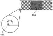
图1是根据本发明一个实施方式的支架传送系统的纵向横截面视图,其中系统的一部分在插图中被放大。Figure 1 is a longitudinal cross-sectional view of a stent delivery system according to one embodiment of the present invention, with a portion of the system enlarged in the inset.
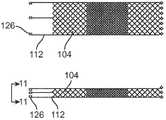
图2是根据本发明一个实施方式的支架的纵向横截面视图,其中支架的一部分在插图中被放大。Figure 2 is a longitudinal cross-sectional view of a stent according to one embodiment of the present invention, with a portion of the stent enlarged in the inset.
图3是根据本发明一个实施方式的两个连接件的详细的侧视图。Figure 3 is a detailed side view of two connectors according to one embodiment of the invention.
图4是根据本发明一个实施方式的支架/推动器线联结处的详细的纵向横截面视图。Figure 4 is a detailed longitudinal cross-sectional view of a stent/pusher wire junction according to one embodiment of the present invention.
图5是通过图4的线5-5的详细的横截面图。FIG. 5 is a detailed cross-sectional view through line 5-5 of FIG. 4 .
图6是根据本发明一个实施方式的两个连接件的详细的侧视图。Figure 6 is a detailed side view of two connectors according to one embodiment of the invention.
图7A和7B分别是通过图6中的线7A-7A和7B-7B的详细的横截面视图。7A and 7B are detailed cross-sectional views through
图8是根据本发明一个实施方式的支架/推动器线联结点的详细的纵向横截面视图。Figure 8 is a detailed longitudinal cross-sectional view of a stent/pusher wire junction according to one embodiment of the present invention.
图9是通过图8的线9-9的详细的横截面图。FIG. 9 is a detailed cross-sectional view through line 9-9 of FIG. 8 .
图10是根据本发明一个实施方式的支架的两个纵向横截面视图。Figure 10 is two longitudinal cross-sectional views of a stent according to one embodiment of the present invention.
图11是通过图10的线11-11的详细的横截面图。FIG. 11 is a detailed cross-sectional view through line 11 - 11 of FIG. 10 .
图12是根据本发明一个实施方式的推动器线的详细的纵向横截面视图。Figure 12 is a detailed longitudinal cross-sectional view of a pusher wire according to one embodiment of the present invention.
图13是根据本发明一个实施方式的支架/推动器线联结处的详细的纵向横截面视图。Figure 13 is a detailed longitudinal cross-sectional view of a stent/pusher wire junction according to one embodiment of the present invention.
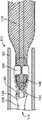
图14和15是根据本发明一个实施方式的支架/推动器线联结处的详细的侧面立体图,其中为清楚起见导管已被切除。Figures 14 and 15 are detailed side perspective views of a stent/pusher wire junction in accordance with one embodiment of the present invention with the catheter cut away for clarity.
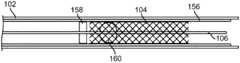
图16-19是根据本发明多个实施方式的支架/推动器线联结处的纵向横截面视图。16-19 are longitudinal cross-sectional views of a stent/pusher wire junction according to various embodiments of the invention.
具体实施方式Detailed ways
图1示出了根据本发明一个实施方式的支架传送系统100。支架传送系统100具有导管102、支架104、和推动器线106。如图1中所示,支架104的近端在环108中终止,并且推动器线106包括设置在环108附近的横向突出部110。环108和突出部110是可释放地附接支架104和推动器线106的两个连接件。推动器线106可以扩张到支架104中,如图1所示,或者推动器线106可以在支架104的近端处终止。Figure 1 illustrates a
支架104可以由金属和非金属材料制成。金属材料包括但不限于镍钛诺、不锈钢、诸如埃尔吉洛伊非磁性合金的基于钴的合金、铂、金、钛、钽、铌,以及它们的组合以及其它的生物可适应材料,以及聚合物材料。金属支架材料可以具有钽、金、铂、铱或者它们组合的内部芯以及镍钛诺的外部构件或层以提供复合丝状体来改进辐射不能透过性或者可见性。非金属材料包括但不限于聚酯、诸如聚对苯二甲酸乙二醇酯(PET)的聚酯、聚丙烯、聚乙烯、聚亚安酯、聚烯烃、乙烯聚合物、聚亚甲基、聚酰胺、萘烷二羧基衍生物、天然丝、和聚四氟乙烯。非金属材料还包括碳、玻璃、和陶瓷。由例如镍钛诺的记忆材料制成的支架104可以被偏压以基于丝状体材料的记忆特性而呈现扩张的形式。在编织的支架中,可以通过在支架104的近端上对扩展的编织丝状体112热处理而形成环108。可替换地,环108可以预成型并且结合到支架104。Bracket 104 can be made of metallic and non-metallic materials. Metallic materials include, but are not limited to, Nitinol, stainless steel, cobalt-based alloys such as Elgiloy, platinum, gold, titanium, tantalum, niobium, combinations thereof, and other biocompatible materials, and polymer material. The metal stent material may have an inner core of tantalum, gold, platinum, iridium, or combinations thereof and an outer member or layer of nitinol to provide a composite filament for improved radiopacity or visibility. Non-metallic materials include, but are not limited to, polyesters, polyesters such as polyethylene terephthalate (PET), polypropylene, polyethylene, polyurethane, polyolefins, ethylene polymers, polymethylene, Polyamide, decalin dicarboxy derivatives, natural silk, and polytetrafluoroethylene. Non-metallic materials also include carbon, glass, and ceramics. A
导管102可以由任何合适的生物可适应材料制成并且衬以类似TeflonTM的低摩擦材料。推动器线106可以由海波管(hypotube)或实心线制成。突出部10可以预成型并且结合到推动器线106。可替换的实施方式包括第二导管(未示出),该第二导管在导管102与支架104和推动器线106之间形成护套。
在图1的插图中示出了环108接近突出部110,即在本申请中附图中所示位于突出部110的左边。因为在导管102的腔114中的紧配合,突出部110在近端与环108邻接。当推动器线106在近端被拉动时,突出部110在近端拉动环108,环108进而在近端拉动支架104。由于导管102的腔114中的紧配合,突出部110还与支架104的内部径向地邻接。当推动器线106在远端被推动时,与本文中描述的缓冲件类似,横向突出部110在远端推动支架104穿过导管102。The
由导管102、环108、以及突出部110形成的联结处116足够强以将局部未加护套的支架104拉回到导管102(支架104从该导管展开)中。例如,图1示出了约50%展开的支架104。在近端拉动推动器线106将会使支架104拉回到导管102中并且使支架104径向地压缩。The
如图2所示,一旦自扩张支架104被推出导管102,支架就变得完全扩张。一旦支架104扩张,环108便不再与突出部110邻接。然后推动器线106与导管102能在近端被收回,使支架104在其插入点处保持在脉管系统中。As shown in FIG. 2, once the self-expanding
图3-5示出了根据本发明另一实施方式的支架传送系统100。在该实施方式中,连接件是连接到支架104的弯曲线118、以及位于推动器线106的横向表面上的腔室120。如上所述,形成为波浪形状的弯曲线118可以通过对支架104的延伸编织丝状体112热处理而形成。可替换地,弯曲线118可以预成型并且结合到支架104。腔室120可以被蚀刻于形成推动器线106的海波管的侧面中。3-5 illustrate a
如图5所示,延伸编织丝状体112和弯曲线118沿着径向方向被居中地偏压。当支架104在推动器线106周围压缩时,该偏压将弯曲线118推动到腔室120中。腔114对于压缩的支架104和推动器线106来说是紧配合。因此,如图4和5所示,当弯曲线118被推到腔室120中时,支架104和推动器线106被可释放地附接并且作为一体沿着导管102的纵向轴线移动。具体地说,当推动器线106在近端被拉动时,腔室120的远端表面122与弯曲线118邻接,并且沿着近端方向拉动弯曲线118和附接到其上的支架104。一旦支架104完全地离开导管102,支架104便扩张并且弯曲线118离开腔室120,以使展开的支架104从推进器线106分离。As shown in FIG. 5 , the elongated braided
图6-9示出了根据本发明又一实施方式的支架传送系统100。在该实施方式中,连接件是平面化元件124、以及位于推动器线106的横向表面上的腔室120。如图7A所示,具有卵形横截面的平面化元件124可以通过使支架104的延伸编织丝状体112平面化而形成。可替换地,平面化元件124可以预成型并且结合到支架104。腔室120可以被蚀刻于形成推动器线106的海波管的侧面中。6-9 illustrate a
如图9所示,延伸编织丝状体112和平面化元件124沿着径向方向被居中地偏压。当支架104在推动器线106周围压缩时,该偏压将平面化元件124推动到腔室120中。腔114对于压缩的支架104和推动器线106来说是紧配合。因此,如图8和9所示,当平面化元件124被推到腔室120中时,支架104和推动器线106被可释放地附接并且作为一体沿着导管102的纵向轴线移动。具体地说,当推动器线106在近端被拉动时,腔室120的远端表面122与平面化元件124邻接,并且沿着近端方向拉动平面化元件124和附接到其上的支架104。一旦支架104完全地离开导管102,支架104便扩张并且平面化元件124离开腔室120,以使展开的支架104从推进器线106分离。As shown in FIG. 9, the extending braided
图10-13示出了根据本发明又一实施方式的支架传送系统100。在该实施方式中,连接件是多个棘爪126和一环形凹口128,该环形凹口由从推动器线106的横向表面延伸的缓冲件形成。棘爪126可以通过将铂切片或者其它标记夹持到支架104的延伸编织丝状体112的端部而形成。可替换地,棘爪126可以通过使延伸编织丝状体112的端部成形而预成型。缓冲件是由诸如聚亚安酯或硅树脂的柔软可变形塑料制成的、并且结合到形成推动器线106的海波管的侧面的管状径向突出部。推动或拉动支架的一些缓冲件(近端缓冲件和重新加护套缓冲件)可以由以线圈、环或者短管形式的金属材料制成,并且附接到推动器线106。10-13 illustrate a
该实施方式具有四个缓冲件:近端缓冲件130、重新加护套缓冲件132、中间缓冲件134、以及远端缓冲件136。其它的实施方式具有多个中间缓冲件134。当支架104被装载到推动器线106上时,近端缓冲件130位于棘爪126的近端,并且重新加护套缓冲件132位于棘爪126的远端。当支架104装载到推动器线106上时,近端缓冲件130和重新加护套缓冲件132形成容纳棘爪126的凹口128。中间缓冲件134与支架104的中间部分相接触,并且远端缓冲件136位于支架104的远端。当支架104被装载到推动器线106上时,所有的缓冲件130、132、134、136均与支架104或者棘爪126接触。该增加的接触在插入和展开期间提供了支架104上的更大的控制。This embodiment has four bumpers: a
如图11所示,延伸编织丝状体112和棘爪126沿着径向方向被居中地偏压。当支架104在推动器线106周围压缩时,该偏压将棘爪126推动到凹口128中。腔114对于压缩的支架104和推动器线106来说是紧配合。因此,如图13所示,当棘爪126被推到凹口128中时,支架104和推动器线106被可释放地附接并且作为一体沿着导管102的纵向轴线移动。具体地说,当推动器线106在近端被拉动时,重新加护套缓冲件132与棘爪126相邻接,并且沿着近端方向拉动棘爪126和附接到其上的支架104。一旦支架104完全地离开导管102,支架104便扩张并且棘爪126离开凹口128,以使展开的支架104从推进器线106分离。As shown in FIG. 11 , the elongated braided
图14和15示出了根据本发明再一实施方式的支架传送系统100。在该实施方式中,推动器线106包括海波管138,该海波管具有设置在其远端上的漏斗状缓冲件140并且限定推动器线腔142。推动器线106还包括芯线144,该芯线设置在推动器线腔142中并且具有设置在其上的中间缓冲件146。中间缓冲件146在侧面上成形为高脚杯状,在中间缓冲件146的中部中具有凹入部148。推动器线106还包括从推动器线腔142沿着远端方向延伸的一对钳状保持件150。保持件150由如镍钛诺的形状记忆材料制成,并且被偏压在打开位置中,除非当插入到导管102中时保持件150受到限制,或者保持件150通过在近端被拉入漏斗状缓冲件140中而被推动得闭合。14 and 15 illustrate a
当保持件150闭合时,保持件在中间缓冲件146中围绕凹入部148闭合。通过将支架104的近端穿入保持件150与中间缓冲件146之间,而使支架104装载到推动器线106上。然后保持件150和芯线144在近端被拉动到推动器线腔142中直到保持件150围绕凹入部148闭合并且将支架104保持到中间缓冲件146。因为推动器线腔142小于在中间缓冲件146周围闭合的保持件150的横截面积,所以保持件150和中间缓冲件146均未能够在近端被拉入到推动器线腔142中。当保持件150围绕支架104和中间缓冲件146闭合时,支架104和推动器线106被可释放地附接并且作为一体沿着导管102的纵向轴线移动。具体地说,当推动器线106在近端被拉动时,保持件150和中间缓冲件146沿着近端方向拉动支架104.如图15所示,一旦支架104完全离开导管102,保持件150扩张,并且展开的支架104从推出器线106分离。When the
在可替换的实施方式中,在芯线144与推动器腔142之间没有相对移动。实际上,推动器线106可以是没有推动器线腔142或者芯线144的实心线。在该实施方式中,在微型导管102的内部保持件150的变形使保持件150围绕凹入部148闭合,并且使支架104保持在中间缓冲件146上。一旦保持件150离开微型导管102,保持件150释放以展开支架104。In an alternative embodiment, there is no relative movement between the
图16和17示出了本发明的另一实施方式,其中支架104被保持在推动器线106上,一个或两个杯152固定到推动器线106处。当使用两个杯时,杯152构造为使得它们的开口154面向彼此。杯152可以预成型,并且然后结合到推动器线106。压缩的支架104套装于推动器线106,支架104的每个端部都保持在杯152中。只要支架104位于导管102中,便防止扩张并且保持处于其压缩的形状中。在这种形式中,杯152将施加到推动器线106的任何作用力传送到支架104并且允许支架104沿着导管102的纵向轴线移动。如图17所示,当支架104离开导管102时,支架104径向扩张并且沿着纵向轴线变短。当支架104的两端均扩张和缩短移出相应的杯152之外时,导管102和推动器线106可以在近端被移除。Figures 16 and 17 show another embodiment of the invention in which the
图18和19示出了本发明的再一实施方式,其中支架104完全地被护套156所容纳。如图19所示,附接到推动器线106的近端缓冲件158和中间缓冲件160允许支架104保持就位,同时护套156和导管102在近端收缩以暴露支架104。在拉出套156之前支架被推到导管102的外部,同时保持推动器线106静止。只要护套156仍覆盖中间缓冲件160,那么因为支架未被释放,则支架104就能被推回到导管102中。一旦护套156在近端完全收缩到缓冲件158,那么支架104将不可重新加护套。如果护套156和导管102均在近端收缩到近端缓冲件158,则支架104将会径向地扩张到展开的尺寸。近端缓冲件152可以预成型,并且然后结合到推动器线106。中间缓冲件160是管状径向突出部,该管状径向突出部由诸如聚亚安酯或者硅树脂的柔软可变形塑料制成并且结合到形成推动器线106的海波管的侧面。18 and 19 illustrate yet another embodiment of the invention in which the
Claims (15)
Translated fromChineseApplications Claiming Priority (3)
| Application Number | Priority Date | Filing Date | Title |
|---|---|---|---|
| US23004809P | 2009-07-30 | 2009-07-30 | |
| US61/230,048 | 2009-07-30 | ||
| PCT/US2010/043984WO2011014814A2 (en) | 2009-07-30 | 2010-07-30 | Stent delivery system |
Publications (1)
| Publication Number | Publication Date |
|---|---|
| CN102481197Atrue CN102481197A (en) | 2012-05-30 |
Family
ID=42830317
Family Applications (1)
| Application Number | Title | Priority Date | Filing Date |
|---|---|---|---|
| CN2010800339557APendingCN102481197A (en) | 2009-07-30 | 2010-07-30 | Stent Delivery System |
Country Status (5)
| Country | Link |
|---|---|
| US (1) | US8241345B2 (en) |
| EP (1) | EP2489335A2 (en) |
| JP (1) | JP2013500792A (en) |
| CN (1) | CN102481197A (en) |
| WO (1) | WO2011014814A2 (en) |
Cited By (4)
| Publication number | Priority date | Publication date | Assignee | Title |
|---|---|---|---|---|
| CN104042379A (en)* | 2013-03-13 | 2014-09-17 | 德普伊新特斯产品有限责任公司 | Capture Tube Mechanism For Delivering And Releasing A Stent |
| CN104055609A (en)* | 2013-03-11 | 2014-09-24 | 德普伊新特斯产品有限责任公司 | Stent Delivery System And Method |
| CN106137488A (en)* | 2016-08-30 | 2016-11-23 | 苏州法兰克曼医疗器械有限公司 | A kind of stent delivery system |
| CN106264808A (en)* | 2016-08-29 | 2017-01-04 | 有研医疗器械(北京)有限公司 | One is accurately positioned esophageal stents appear induction system |
Families Citing this family (101)
| Publication number | Priority date | Publication date | Assignee | Title |
|---|---|---|---|---|
| US6866679B2 (en) | 2002-03-12 | 2005-03-15 | Ev3 Inc. | Everting stent and stent delivery system |
| US20060206200A1 (en) | 2004-05-25 | 2006-09-14 | Chestnut Medical Technologies, Inc. | Flexible vascular occluding device |
| CA2758946C (en) | 2004-05-25 | 2014-10-21 | Tyco Healthcare Group Lp | Vascular stenting for aneurysms |
| US8617234B2 (en) | 2004-05-25 | 2013-12-31 | Covidien Lp | Flexible vascular occluding device |
| CA2565106C (en) | 2004-05-25 | 2013-11-05 | Chestnut Medical Technologies, Inc. | Flexible vascular occluding device |
| US8623067B2 (en) | 2004-05-25 | 2014-01-07 | Covidien Lp | Methods and apparatus for luminal stenting |
| DE102005003632A1 (en) | 2005-01-20 | 2006-08-17 | Fraunhofer-Gesellschaft zur Förderung der angewandten Forschung e.V. | Catheter for the transvascular implantation of heart valve prostheses |
| AU2005332044B2 (en) | 2005-05-25 | 2012-01-19 | Covidien Lp | System and method for delivering and deploying and occluding device within a vessel |
| EP1988851A2 (en)* | 2006-02-14 | 2008-11-12 | Sadra Medical, Inc. | Systems and methods for delivering a medical implant |
| US8152833B2 (en) | 2006-02-22 | 2012-04-10 | Tyco Healthcare Group Lp | Embolic protection systems having radiopaque filter mesh |
| US7896915B2 (en) | 2007-04-13 | 2011-03-01 | Jenavalve Technology, Inc. | Medical device for treating a heart valve insufficiency |
| BR112012021347A2 (en) | 2008-02-26 | 2019-09-24 | Jenavalve Tecnology Inc | stent for positioning and anchoring a valve prosthesis at an implantation site in a patient's heart |
| US9044318B2 (en) | 2008-02-26 | 2015-06-02 | Jenavalve Technology Gmbh | Stent for the positioning and anchoring of a valvular prosthesis |
| US9387312B2 (en) | 2008-09-15 | 2016-07-12 | Brightwater Medical, Inc. | Convertible nephroureteral catheter |
| US10856978B2 (en) | 2010-05-20 | 2020-12-08 | Jenavalve Technology, Inc. | Catheter system |
| WO2011147849A1 (en) | 2010-05-25 | 2011-12-01 | Jenavalve Technology Inc. | Prosthetic heart valve and transcatheter delivered endoprosthesis comprising a prosthetic heart valve and a stent |
| FR2976478B1 (en)* | 2011-06-17 | 2013-07-05 | Newco | DEVICE FOR DELIVERING STENT IN A BLOOD OR SIMILAR VESSEL. |
| US9192496B2 (en) | 2011-10-31 | 2015-11-24 | Merit Medical Systems, Inc. | Systems and methods for sheathing an implantable device |
| EP2628470B1 (en)* | 2012-02-16 | 2020-11-25 | Biotronik AG | Release device for releasing a medical implant from a catheter and catheter having a release device and method for clamping an implant therein |
| US20130226278A1 (en) | 2012-02-23 | 2013-08-29 | Tyco Healthcare Group Lp | Methods and apparatus for luminal stenting |
| AU2015202690B2 (en)* | 2012-02-23 | 2016-09-22 | Covidien Lp | Methods and apparatus for luminal stenting |
| US9072624B2 (en) | 2012-02-23 | 2015-07-07 | Covidien Lp | Luminal stenting |
| US9078659B2 (en) | 2012-04-23 | 2015-07-14 | Covidien Lp | Delivery system with hooks for resheathability |
| EP2676642A1 (en)* | 2012-06-18 | 2013-12-25 | Biotronik AG | Release device for releasing a medical implant from a catheter |
| US9724222B2 (en) | 2012-07-20 | 2017-08-08 | Covidien Lp | Resheathable stent delivery system |
| US9649212B2 (en)* | 2012-08-30 | 2017-05-16 | Biotronik Ag | Release device for releasing a medical implant from a catheter and catheter comprising a release device |
| US9301831B2 (en) | 2012-10-30 | 2016-04-05 | Covidien Lp | Methods for attaining a predetermined porosity of a vascular device |
| US9452070B2 (en) | 2012-10-31 | 2016-09-27 | Covidien Lp | Methods and systems for increasing a density of a region of a vascular device |
| US9943427B2 (en) | 2012-11-06 | 2018-04-17 | Covidien Lp | Shaped occluding devices and methods of using the same |
| CN104717942A (en)* | 2013-01-08 | 2015-06-17 | 泰尔茂株式会社 | Stent delivery device |
| US9157174B2 (en) | 2013-02-05 | 2015-10-13 | Covidien Lp | Vascular device for aneurysm treatment and providing blood flow into a perforator vessel |
| US20140228822A1 (en)* | 2013-02-13 | 2014-08-14 | Biotronik Ag | Cover device for covering an at least partly released medical implant in a catheter, and catheter comprising a cover device, and also method for covering an at least partly released medical implant with such a cover device |
| CN103190968B (en)* | 2013-03-18 | 2015-06-17 | 杭州启明医疗器械有限公司 | Bracket and stably-mounted artificial valve displacement device with same |
| EP2813195A1 (en) | 2013-06-13 | 2014-12-17 | Cardiatis S.A. | Stent delivery system |
| US10130500B2 (en) | 2013-07-25 | 2018-11-20 | Covidien Lp | Methods and apparatus for luminal stenting |
| US10045867B2 (en) | 2013-08-27 | 2018-08-14 | Covidien Lp | Delivery of medical devices |
| US9782186B2 (en) | 2013-08-27 | 2017-10-10 | Covidien Lp | Vascular intervention system |
| EP3038570B1 (en)* | 2013-08-27 | 2017-11-22 | Covidien LP | Luminal stenting |
| CN105491978A (en) | 2013-08-30 | 2016-04-13 | 耶拿阀门科技股份有限公司 | Radially collapsible frame for a prosthetic valve and method for manufacturing such a frame |
| US20150297250A1 (en)* | 2014-04-16 | 2015-10-22 | Covidien Lp | Systems and methods for catheter advancement |
| US11110286B2 (en)* | 2014-06-10 | 2021-09-07 | Biotronik Se & Co. Kg | Delivery system for an implantable medical device |
| EP3936088A1 (en)* | 2014-08-12 | 2022-01-12 | Merit Medical Systems, Inc. | Systems and methods for coupling and decoupling a catheter |
| PL3653177T3 (en) | 2015-01-11 | 2022-01-31 | Ascyrus Medical, Llc | Hybrid device for surgical aortic repair |
| US9597213B2 (en)* | 2015-02-12 | 2017-03-21 | Abbott Cardiovascular Systems Inc. | Handle mechanism for actuating delivery catheter |
| WO2016141295A1 (en) | 2015-03-05 | 2016-09-09 | Merit Medical Systems, Inc. | Vascular prosthesis deployment device and method of use |
| DE102015103240A1 (en) | 2015-03-05 | 2016-09-08 | Phenox Gmbh | implant delivery |
| EP3270825B1 (en) | 2015-03-20 | 2020-04-22 | JenaValve Technology, Inc. | Heart valve prosthesis delivery system |
| US10709555B2 (en) | 2015-05-01 | 2020-07-14 | Jenavalve Technology, Inc. | Device and method with reduced pacemaker rate in heart valve replacement |
| US10470906B2 (en) | 2015-09-15 | 2019-11-12 | Merit Medical Systems, Inc. | Implantable device delivery system |
| JP6854282B2 (en)* | 2015-09-18 | 2021-04-07 | テルモ株式会社 | Pressable implant delivery system |
| JP6816126B2 (en) | 2015-09-18 | 2021-01-20 | マイクロベンション インコーポレイテッドMicrovention, Inc. | Releasable delivery system |
| JP6857182B2 (en)* | 2015-12-02 | 2021-04-14 | アトス メディカル アクティエボラーグ | A device for securely mounting and mounting a tubular device on a flexible wall |
| US10660776B2 (en)* | 2016-04-11 | 2020-05-26 | Boston Scientific Scimed, Inc. | Stent delivery system with collapsible loading frame |
| US10022255B2 (en)* | 2016-04-11 | 2018-07-17 | Idev Technologies, Inc. | Stent delivery system having anisotropic sheath |
| WO2017195125A1 (en) | 2016-05-13 | 2017-11-16 | Jenavalve Technology, Inc. | Heart valve prosthesis delivery system and method for delivery of heart valve prosthesis with introducer sheath and loading system |
| EP3500191B1 (en)* | 2016-08-17 | 2020-09-23 | Neuravi Limited | A clot retrieval system for removing occlusive clot from a blood vessel |
| GB201615219D0 (en) | 2016-09-07 | 2016-10-19 | Vascutek Ltd And Univ Medical Center Hamburg-Eppendorf (Uke) | Hybrid prosthesis and delivery system |
| CN115054413A (en) | 2016-09-29 | 2022-09-16 | 美国医疗设备有限公司 | Method of adjusting effective length of stent and prosthesis delivery catheter assembly |
| GB2554670B (en)* | 2016-09-30 | 2022-01-05 | Vascutek Ltd | A vascular graft |
| US11426276B2 (en)* | 2016-10-12 | 2022-08-30 | Medtronic Vascular, Inc. | Stented prosthetic heart valve delivery system having an expandable bumper |
| CN108056798B (en)* | 2016-11-08 | 2021-06-04 | 艾柯医疗器械(北京)有限公司 | Support pushing system, corresponding blood flow guiding device and blood flow guiding device assembling method |
| US10376396B2 (en) | 2017-01-19 | 2019-08-13 | Covidien Lp | Coupling units for medical device delivery systems |
| WO2018138658A1 (en) | 2017-01-27 | 2018-08-02 | Jenavalve Technology, Inc. | Heart valve mimicry |
| US10556287B2 (en) | 2017-02-21 | 2020-02-11 | Abbott Cardiovascular Systems Inc. | Method for selectively pretinning a guidewire core |
| ES2863978T3 (en) | 2017-02-24 | 2021-10-13 | Bolton Medical Inc | System for radially constricting a stent graft |
| EP3932373B1 (en) | 2017-02-24 | 2022-12-21 | Bolton Medical, Inc. | Delivery system for radially constricting a stent graft |
| WO2018156854A1 (en) | 2017-02-24 | 2018-08-30 | Bolton Medical, Inc. | Radially adjustable stent graft delivery system |
| EP3534837A1 (en) | 2017-02-24 | 2019-09-11 | Bolton Medical, Inc. | Constrainable stent graft, delivery system and methods of use |
| WO2018156847A1 (en) | 2017-02-24 | 2018-08-30 | Bolton Medical, Inc. | Delivery system and method to radially constrict a stent graft |
| WO2018156850A1 (en) | 2017-02-24 | 2018-08-30 | Bolton Medical, Inc. | Stent graft with fenestration lock |
| WO2018156848A1 (en) | 2017-02-24 | 2018-08-30 | Bolton Medical, Inc. | Vascular prosthesis with crimped adapter and methods of use |
| WO2018156851A1 (en) | 2017-02-24 | 2018-08-30 | Bolton Medical, Inc. | Vascular prosthesis with moveable fenestration |
| WO2018156849A1 (en) | 2017-02-24 | 2018-08-30 | Bolton Medical, Inc. | Vascular prosthesis with fenestration ring and methods of use |
| ES2954897T3 (en) | 2017-02-24 | 2023-11-27 | Bolton Medical Inc | Constrained Wrap Stent Graft Delivery System |
| US11628078B2 (en) | 2017-03-15 | 2023-04-18 | Merit Medical Systems, Inc. | Transluminal delivery devices and related kits and methods |
| EP4467111A3 (en) | 2017-03-15 | 2025-03-05 | Merit Medical Systems, Inc. | Transluminal stents |
| USD836194S1 (en) | 2017-03-21 | 2018-12-18 | Merit Medical Systems, Inc. | Stent deployment device |
| GB2562065A (en) | 2017-05-02 | 2018-11-07 | Vascutek Ltd | Endoprosthesis |
| GB201707929D0 (en) | 2017-05-17 | 2017-06-28 | Vascutek Ltd | Tubular medical device |
| GB201715658D0 (en) | 2017-09-27 | 2017-11-08 | Vascutek Ltd | An endoluminal device |
| CN110121319B (en) | 2017-10-31 | 2023-05-09 | 波顿医疗公司 | Distal torque component, delivery system, and method of use thereof |
| US11413176B2 (en) | 2018-04-12 | 2022-08-16 | Covidien Lp | Medical device delivery |
| US11071637B2 (en) | 2018-04-12 | 2021-07-27 | Covidien Lp | Medical device delivery |
| US11123209B2 (en) | 2018-04-12 | 2021-09-21 | Covidien Lp | Medical device delivery |
| US10786377B2 (en) | 2018-04-12 | 2020-09-29 | Covidien Lp | Medical device delivery |
| US10441449B1 (en) | 2018-05-30 | 2019-10-15 | Vesper Medical, Inc. | Rotary handle stent delivery system and method |
| US10449073B1 (en) | 2018-09-18 | 2019-10-22 | Vesper Medical, Inc. | Rotary handle stent delivery system and method |
| GB201820898D0 (en) | 2018-12-20 | 2019-02-06 | Vascutek Ltd | Stent device |
| US11413174B2 (en) | 2019-06-26 | 2022-08-16 | Covidien Lp | Core assembly for medical device delivery systems |
| US12226327B2 (en) | 2020-04-15 | 2025-02-18 | Merit Medical Systems, Inc. | Systems and methods for coupling and decoupling a catheter |
| US11219541B2 (en) | 2020-05-21 | 2022-01-11 | Vesper Medical, Inc. | Wheel lock for thumbwheel actuated device |
| EP4185239A4 (en) | 2020-07-24 | 2024-08-07 | Merit Medical Systems, Inc. | ESOPHAGEAL STENT PROSTHESES AND RELATED METHODS |
| CN113599022A (en)* | 2020-10-12 | 2021-11-05 | 宁波健世科技股份有限公司 | Valve prosthesis conveying system convenient to control |
| CA3194910A1 (en) | 2020-10-26 | 2022-05-05 | Tiffany ETHRIDGE | Esophageal stents with helical thread |
| US12042413B2 (en) | 2021-04-07 | 2024-07-23 | Covidien Lp | Delivery of medical devices |
| US12109137B2 (en) | 2021-07-30 | 2024-10-08 | Covidien Lp | Medical device delivery |
| US11944558B2 (en) | 2021-08-05 | 2024-04-02 | Covidien Lp | Medical device delivery devices, systems, and methods |
| EP4482439A1 (en) | 2022-02-23 | 2025-01-01 | Elum Technologies, Inc. | Neurovascular flow diverter and delivery systems |
| WO2024102411A1 (en) | 2022-11-09 | 2024-05-16 | Jenavalve Technology, Inc. | Catheter system for sequential deployment of an expandable implant |
| US12213676B2 (en) | 2023-02-22 | 2025-02-04 | eLum Technologies, Inc. | Systems and methods for customizable flow diverter implants |
| CN117426917B (en)* | 2023-12-20 | 2024-04-09 | 北京华脉泰科医疗器械股份有限公司 | Tectorial membrane support conveyor |
Citations (7)
| Publication number | Priority date | Publication date | Assignee | Title |
|---|---|---|---|---|
| EP0657147A2 (en)* | 1993-11-04 | 1995-06-14 | C.R. Bard, Inc. | Non-migrating vascular prosthesis and minimally invasive placement system therefor |
| US5824041A (en)* | 1994-06-08 | 1998-10-20 | Medtronic, Inc. | Apparatus and methods for placement and repositioning of intraluminal prostheses |
| WO1999047075A1 (en)* | 1998-03-17 | 1999-09-23 | Medicorp S.A. | Reversible-action endoprosthesis delivery device |
| US20020183827A1 (en)* | 2001-06-01 | 2002-12-05 | American Medical Systems | Stent delivery device and method |
| US20040006380A1 (en)* | 2002-07-05 | 2004-01-08 | Buck Jerrick C. | Stent delivery system |
| US20040204749A1 (en)* | 2003-04-11 | 2004-10-14 | Richard Gunderson | Stent delivery system with securement and deployment accuracy |
| CN2840949Y (en)* | 2005-06-17 | 2006-11-29 | 赵珺 | A kind of combination type zona vascuiosa membrane support of magnetic tape trailer hook |
Family Cites Families (3)
| Publication number | Priority date | Publication date | Assignee | Title |
|---|---|---|---|---|
| EP1488735B1 (en)* | 2003-06-17 | 2007-06-13 | Raymond Moser | Instrumented retrievable implantable device |
| US20070118207A1 (en)* | 2005-05-04 | 2007-05-24 | Aga Medical Corporation | System for controlled delivery of stents and grafts |
| US8100959B2 (en)* | 2007-03-09 | 2012-01-24 | Pulmonx Corporation | Loading device for a pulmonary implant |
- 2010
- 2010-07-30JPJP2012523102Apatent/JP2013500792A/ennot_activeWithdrawn
- 2010-07-30WOPCT/US2010/043984patent/WO2011014814A2/enactiveApplication Filing
- 2010-07-30CNCN2010800339557Apatent/CN102481197A/enactivePending
- 2010-07-30USUS12/847,241patent/US8241345B2/enactiveActive
- 2010-07-30EPEP12001957Apatent/EP2489335A2/ennot_activeWithdrawn
Patent Citations (7)
| Publication number | Priority date | Publication date | Assignee | Title |
|---|---|---|---|---|
| EP0657147A2 (en)* | 1993-11-04 | 1995-06-14 | C.R. Bard, Inc. | Non-migrating vascular prosthesis and minimally invasive placement system therefor |
| US5824041A (en)* | 1994-06-08 | 1998-10-20 | Medtronic, Inc. | Apparatus and methods for placement and repositioning of intraluminal prostheses |
| WO1999047075A1 (en)* | 1998-03-17 | 1999-09-23 | Medicorp S.A. | Reversible-action endoprosthesis delivery device |
| US20020183827A1 (en)* | 2001-06-01 | 2002-12-05 | American Medical Systems | Stent delivery device and method |
| US20040006380A1 (en)* | 2002-07-05 | 2004-01-08 | Buck Jerrick C. | Stent delivery system |
| US20040204749A1 (en)* | 2003-04-11 | 2004-10-14 | Richard Gunderson | Stent delivery system with securement and deployment accuracy |
| CN2840949Y (en)* | 2005-06-17 | 2006-11-29 | 赵珺 | A kind of combination type zona vascuiosa membrane support of magnetic tape trailer hook |
Cited By (8)
| Publication number | Priority date | Publication date | Assignee | Title |
|---|---|---|---|---|
| CN104055609A (en)* | 2013-03-11 | 2014-09-24 | 德普伊新特斯产品有限责任公司 | Stent Delivery System And Method |
| CN104055609B (en)* | 2013-03-11 | 2017-11-24 | 德普伊新特斯产品有限责任公司 | Stent delivery system and method |
| CN104042379A (en)* | 2013-03-13 | 2014-09-17 | 德普伊新特斯产品有限责任公司 | Capture Tube Mechanism For Delivering And Releasing A Stent |
| US10172734B2 (en) | 2013-03-13 | 2019-01-08 | DePuy Synthes Products, Inc. | Capture tube mechanism for delivering and releasing a stent |
| US10786378B2 (en) | 2013-03-13 | 2020-09-29 | DePuy Synthes Products, Inc. | Capture tube mechanism for delivering and releasing a stent |
| CN106264808A (en)* | 2016-08-29 | 2017-01-04 | 有研医疗器械(北京)有限公司 | One is accurately positioned esophageal stents appear induction system |
| CN106264808B (en)* | 2016-08-29 | 2017-12-15 | 有研医疗器械(北京)有限公司 | One kind is accurately positioned esophageal stents induction system |
| CN106137488A (en)* | 2016-08-30 | 2016-11-23 | 苏州法兰克曼医疗器械有限公司 | A kind of stent delivery system |
Also Published As
| Publication number | Publication date |
|---|---|
| JP2013500792A (en) | 2013-01-10 |
| WO2011014814A3 (en) | 2011-03-31 |
| US8241345B2 (en) | 2012-08-14 |
| US20110190862A1 (en) | 2011-08-04 |
| WO2011014814A2 (en) | 2011-02-03 |
| EP2489335A2 (en) | 2012-08-22 |
Similar Documents
| Publication | Publication Date | Title |
|---|---|---|
| US8241345B2 (en) | Stent delivery system | |
| US10076434B2 (en) | Stent delivery system | |
| EP1796583B1 (en) | Device for delivering an endovascular stent-graft having a logitudinally unsupported portion | |
| JP2021151495A (en) | Implant retention, detachment, and delivery system | |
| EP1682039B1 (en) | Prosthesis delivery systems | |
| US8303616B2 (en) | Internal restraint for delivery of self-expanding stents | |
| CN102137635B (en) | Bifurcated medical device for treating a target site and related methods | |
| EP2604232B1 (en) | Circumferential trigger wire for deploying an endoluminal prosthesis | |
| CN112807046A (en) | Implant delivery system with braided cup formation | |
| US20150246210A1 (en) | Delivery system and method of use for deployment of self-expandable vascular device | |
| US10524945B2 (en) | Stents twisted prior to deployment and untwisted during deployment | |
| EP3245986A1 (en) | Wire retention and release mechanisms | |
| US20110295358A1 (en) | Endoluminal prosthesis |
Legal Events
| Date | Code | Title | Description |
|---|---|---|---|
| C06 | Publication | ||
| PB01 | Publication | ||
| C10 | Entry into substantive examination | ||
| SE01 | Entry into force of request for substantive examination | ||
| C02 | Deemed withdrawal of patent application after publication (patent law 2001) | ||
| WD01 | Invention patent application deemed withdrawn after publication | Application publication date:20120530 |