CN102480149A - Multifunctional back splint device - Google Patents
Multifunctional back splint deviceDownload PDFInfo
- Publication number
- CN102480149A CN102480149ACN2010105903393ACN201010590339ACN102480149ACN 102480149 ACN102480149 ACN 102480149ACN 2010105903393 ACN2010105903393 ACN 2010105903393ACN 201010590339 ACN201010590339 ACN 201010590339ACN 102480149 ACN102480149 ACN 102480149A
- Authority
- CN
- China
- Prior art keywords
- back clip
- clip device
- wireless charging
- unit
- processing unit
- Prior art date
- Legal status (The legal status is an assumption and is not a legal conclusion. Google has not performed a legal analysis and makes no representation as to the accuracy of the status listed.)
- Pending
Links
- 230000005540biological transmissionEffects0.000claimsabstractdescription40
- 230000006870functionEffects0.000abstractdescription9
- 230000006698inductionEffects0.000abstractdescription2
- 238000010586diagramMethods0.000description6
- 101100215340Solanum tuberosum AC97 geneProteins0.000description3
- 230000004048modificationEffects0.000description2
- 238000012986modificationMethods0.000description2
- 230000009286beneficial effectEffects0.000description1
- 238000005034decorationMethods0.000description1
- 230000007812deficiencyEffects0.000description1
- 230000000694effectsEffects0.000description1
- 238000005516engineering processMethods0.000description1
- 239000004973liquid crystal related substanceSubstances0.000description1
- 238000000034methodMethods0.000description1
- 229920006395saturated elastomerPolymers0.000description1
Images


Landscapes
- Power Sources (AREA)
- Charge And Discharge Circuits For Batteries Or The Like (AREA)
Abstract
Description
Translated fromChinese技术领域technical field
本发明涉及一种背夹装置,且特别涉及一种多功能背夹装置。The invention relates to a back clip device, and in particular to a multifunctional back clip device.
背景技术Background technique
目前,随着手持装置的广泛应用,市面上出现了各种背夹装置。然而,目前的背夹装置功能较为单一,通常仅能提供装饰与保护作用。At present, with the wide application of handheld devices, various back clip devices appear on the market. However, the current clip device has a single function, and usually only provides decoration and protection.
发明内容Contents of the invention
本发明的目的在于提供一种多功能背夹装置,以改善现有技术的缺失。The purpose of the present invention is to provide a multifunctional back clip device to improve the shortcomings of the prior art.
为解决上述技术问题,本发明的技术方案是:In order to solve the problems of the technologies described above, the technical solution of the present invention is:
本发明提供一种多功能背夹装置,其与手持装置配合且包括本体、连接接口、处理单元、无线传输单元以及无线充电单元。本体覆盖于手持装置的背面。连接接口设置于本体且自手持装置接收多媒体数据。处理单元设置于本体且同连接接口相连接,处理单元接收多媒体数据并将多媒体数据转化为压缩数据。无线传输单元设置于本体且同处理单元相连接,无线传输单元接收压缩数据并输出。无线充电单元设置于本体且同处理单元与无线传输单元相连接,无线充电单元用以产生感应电流。The invention provides a multi-functional back clip device, which is matched with a handheld device and includes a body, a connection interface, a processing unit, a wireless transmission unit and a wireless charging unit. The body covers the back of the handheld device. The connection interface is arranged on the body and receives multimedia data from the handheld device. The processing unit is arranged on the body and connected with the connection interface. The processing unit receives the multimedia data and converts the multimedia data into compressed data. The wireless transmission unit is arranged on the body and connected with the processing unit, and the wireless transmission unit receives the compressed data and outputs it. The wireless charging unit is arranged on the body and connected with the processing unit and the wireless transmission unit, and the wireless charging unit is used for generating induced current.
在本发明的一实施例中,处理单元包括多媒体数据编码器。In an embodiment of the invention, the processing unit includes a multimedia data encoder.
在本发明的一实施例中,连接接口为高清晰度多媒体接口(HDMI)或TV-out接口或为两者的组合。In an embodiment of the present invention, the connection interface is a high-definition multimedia interface (HDMI) or a TV-out interface or a combination of both.
在本发明的一实施例中,无线传输单元为WIFI无线传输单元。In an embodiment of the present invention, the wireless transmission unit is a WIFI wireless transmission unit.
在本发明的一实施例中,无线充电单元包括充电线圈、整流器、电流输出端以及可充电电池。整流器连接充电线圈、电流输出端以及可充电电池,可充电电池连接处理单元与无线传输单元。In an embodiment of the present invention, the wireless charging unit includes a charging coil, a rectifier, a current output terminal, and a rechargeable battery. The rectifier is connected to the charging coil, the current output terminal and the rechargeable battery, and the rechargeable battery is connected to the processing unit and the wireless transmission unit.
在本发明的一实施例中,多功能背夹装置能够与无线充电基座配合使用。当多功能背夹装置与无线充电基座之间的距离小于预设值时,无线充电单元产生感应电流。In an embodiment of the present invention, the multifunctional back clip device can be used in conjunction with the wireless charging base. When the distance between the multifunctional back clip device and the wireless charging base is less than a preset value, the wireless charging unit generates an induced current.
本发明的有益效果可以是:The beneficial effects of the present invention can be:
在本发明中,多功能背夹装置利用连接接口、处理单元、无线传输单元实现多媒体数据的无线传输,利用无线充电单元实现无线充电功能。这样,本发明提供的多功能背夹装置同时具有多媒体数据无线传输功能以及无线充电功能。因此,本发明提供的多功能背夹装置不仅改善了先前技术中背夹装置功能单一的不足,而且方便了手持装置的使用。In the present invention, the multi-functional back clip device realizes the wireless transmission of multimedia data by using the connection interface, the processing unit and the wireless transmission unit, and realizes the wireless charging function by using the wireless charging unit. In this way, the multifunctional back clip device provided by the present invention simultaneously has the function of wireless transmission of multimedia data and the function of wireless charging. Therefore, the multifunctional back clip device provided by the present invention not only improves the single-function deficiency of the back clip device in the prior art, but also facilitates the use of the handheld device.
为让本发明的上述和其它目的、特征和优点能更明显易懂,下文特举较佳实施例,并配合附图,作详细说明如下。In order to make the above and other objects, features and advantages of the present invention more comprehensible, preferred embodiments are described below in detail with accompanying drawings.
附图说明Description of drawings
图1为本发明的一较佳实施例的多功能背夹装置与手持装置的示意图;Fig. 1 is a schematic diagram of a multifunctional back clip device and a handheld device according to a preferred embodiment of the present invention;
图2为本发明的一较佳实施例的多功能背夹装置的模块示意图;Fig. 2 is a schematic diagram of modules of a multifunctional back clip device according to a preferred embodiment of the present invention;
图3为本发明的一较佳实施例的多功能背夹装置的局部电路示意图。FIG. 3 is a schematic partial circuit diagram of a multifunctional back clip device according to a preferred embodiment of the present invention.
具体实施方式Detailed ways
图1为本发明的一较佳实施例的多功能背夹装置与手持装置的示意图。图2为本发明的一较佳实施例的多功能背夹装置的模块示意图。如图1与图2所示,本实施例提供的多功能背夹装置1能够与手持装置2、播放装置3以及无线充电基座4配合使用。在此,手持装置2例如为移动电话,播放装置3例如为电视机。然而,本发明对此不作任何限定。在实际应用中,手持装置2也可为MP4播放器或游戏机,播放装置3也可为笔记本电脑或液晶显示器。FIG. 1 is a schematic diagram of a multifunctional back clip device and a handheld device according to a preferred embodiment of the present invention. FIG. 2 is a block diagram of a multifunctional back clip device according to a preferred embodiment of the present invention. As shown in FIG. 1 and FIG. 2 , the multifunctional
在本实施例中,如图1与图2所示,多功能背夹装置1包括本体10、连接接口12、无线传输单元13、处理单元14以及无线充电单元16。其中,连接接口12、无线传输单元13、处理单元14以及无线充电单元16均设置于本体10。处理单元14同连接接口12相连接、无线传输单元13以及无线充电单元16。无线传输单元13同无线充电单元16相连接。In this embodiment, as shown in FIG. 1 and FIG. 2 , the
在本实施例中,如图1所示,多功能背夹装置1的本体10覆盖于手持装置2的背面20。因此,多功能背夹装置1不仅可方便地与手持装置2一起携带,同时也可为手持装置2提供保护作用。In this embodiment, as shown in FIG. 1 , the
在本实施例中,本体10可形成凹陷状的容置区,此容置区的形状与大小可与手持装置2的背面20的形状与大小吻合。因此,手持装置2的背面20可较为稳固地容置于其内。然而,本发明对此不作任何限定。在其它实施例中,也可利用绑带、卡勾、魔鬼毡等其它结构来使多功能背夹装置1的本体10稳固地覆盖于手持装置2的背面20。In this embodiment, the
在本实施例中,如图2所示,多功能背夹装置1可利用连接接口12连接手持装置2。其中,连接接口12可为高清晰度多媒体接口(HDMI)或TV-out接口或为两者的组合。在本实施例中,以连接接口12包括高清晰度多媒体接口(HDMI)与TV-out接口为例进行说明。当手持装置2为iPhone时,多功能背夹装置1可利用TV-out接口连接手持装置2(iPhone)。当手持装置2为PS3时,多功能背夹装置1可利用高清晰度多媒体接口连接手持装置2(PS3)。换言之,多功能背夹装置1可选择性地通过高清晰度多媒体接口与TV-out接口连接不同类型的手持装置2。然而,本发明并不限定于此。在实际应用中,根据手持装置2的类型,多功能背夹装置1的连接接口12可包括其它类型的接口。In this embodiment, as shown in FIG. 2 , the multifunctional
在本实施例中,连接接口12自手持装置2接收多媒体数据D1(例如,影像数据)。处理单元14自连接接口12接收多媒体数据D1并将多媒体数据D1转化为压缩数据D2。无线传输单元13自处理单元14接收压缩数据D2并输出压缩数据D2至播放装置3。关于处理单元14的具体结构容后详述。In this embodiment, the
在本实施例中,多功能背夹装置1利用无线传输单元13与播放装置3实现无线多媒体数据传输。在此,无线传输单元13为WIFI无线传输单元。然而,本发明并不限定于此。在其它实施例中,无线传输单元13也可为蓝牙或红外无线传输单元。In this embodiment, the multifunctional
在本实施例中,多功能背夹装置1利用无线充电单元16与无线充电基座4实现无线充电。如图2所示,无线充电单元16包括充电线圈160、整流器161、电流输出端162以及可充电电池163。其中,整流器161连接充电线圈160、电流输出端162以及可充电电池163。可充电电池163连接处理单元14。电流输出端162可连接手持装置2。然而,本发明并不限定于此。在其它实施例中,无线充电单元16中可不设置可充电电池163,而多功能背夹装置1的电力可直接由电流输出端162提供。In this embodiment, the multi-functional
在本实施例中,具体而言,可充电电池163连接处理单元14与无线传输单元13,从而为多功能背夹装置1提供电力。当多功能背夹装置1与无线充电基座4之间的距离小于预设值时,无线充电单元16产生感应电流。其中,预设值可根据需要设定,本发明对此不作任何限定。在实际应用中,当多功能背夹装置1直接放置于无线充电基座4时,无线充电单元16的充电线圈160与无线充电基座4内部的线圈因感应而彼此磁耦合,从而使充电线圈160产生感应电流。充电线圈160产生的感应电流经由整流器161整流后通过电流输出端162提供给手持装置2,同时,产生的感应电流可为可充电电池163充电。此外,需要注意的是,手持装置2内部可设置可充电电池(图未示)。无线充电单元16的电流输出端162可连接手持装置2的可充电电池,以为其提供充电电流。In this embodiment, specifically, the
在本实施例中,电流输出端162可为通用串行总线(Universal Serial BUS,USB)接口。然而,本发明并不限定于此。In this embodiment, the
另外,为防止可充电电池163过充,无线充电单元16内部可增设微控制器(图未示)与开关(图未示)。微控制器连接可充电电池163与开关,开关设置于整流器161至可充电电池163的供电路径上。具体而言,微控制器可用于侦测可充电电池163的剩余电量,仅当其剩余电量低于某预设值(例如为95%的电池饱和电量)时,微控制器才控制开关导通,以为可充电电池163充电。反之,当可充电电池163的剩余电量高于预设值时,微控制器控制开关断开,以防止可充电电池163过充而损坏。然而,本发明并不限定于此。In addition, to prevent the
图3为本发明的一较佳实施例的多功能背夹装置的局部电路示意图。请参考图2与图3。如图3所示,处理单元14包括多媒体数据编码器140。在此,多媒体数据编码器140为芯片TF630。由于连接接口12自手持装置2接收的多媒体数据D1过大,因此,利用多媒体数据编码器140将多媒体数据D1压缩为压缩数据D2后再进行传输。FIG. 3 is a schematic partial circuit diagram of a multifunctional back clip device according to a preferred embodiment of the present invention. Please refer to Figure 2 and Figure 3. As shown in FIG. 3 , the
在本实施例中,如图3所示,芯片EP9853提供高清晰度多媒体接口(HDMI),且其同多媒体数据编码器140(芯片TF630)相连接。此外,芯片EP9853利用数字-模拟转换器同声卡AC97相连接,且声卡AC97同多媒体数据编码器140相连接。因此,若多媒体数据D1包括声音数据,则声卡AC97可解码多媒体数据D1中的声音数据后再将其传输至多媒体数据编码器140。In this embodiment, as shown in FIG. 3 , the chip EP9853 provides a high-definition multimedia interface (HDMI), and it is connected with the multimedia data encoder 140 (chip TF630). In addition, the chip EP9853 is connected with the sound card AC97 by using a digital-to-analog converter, and the sound card AC97 is connected with the
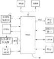
在本实施例中,多媒体数据编码器140的时钟频率为10MHz,且多媒体数据编码器140还同无线传输单元13相连接、EEPROM、SDRAM、RS232接口、闪存等元件。其中,无线传输单元13可为WIFI无线传输单元。闪存中存储多功能背夹装置1的开机信息以及驱动程序。EEPROM中可存储用于调整影像数据显示质量的相关程序。即,多功能背夹装置1可根据手持装置2的屏幕分辨率来运用EEPROM中储存的相关程序自动调整传输至播放装置3的影像数据,以使播放装置3达到最佳的显示效果。SDRAM可于多媒体数据传输过程中用于暂存数据。多功能背夹装置1利用RS232接口作内部测试除错用(debug)。另外,多媒体数据编码器140还可连接指示元件。指示元件例如可为LED指示灯,用于指示多功能背夹装置1的工作状态。例如,当多功能背夹装置1开启后,指示元件可显示红色。当多功能背夹装置1开始传输多媒体数据时,指示元件可显示绿色。在此,多功能背夹装置1的指示元件利用GPIO实现其色彩变换。然而,本发明并不限定于此。In this embodiment, the clock frequency of the
综上所述,本发明较佳实施例提供的多功能背夹装置利用连接接口、处理单元、无线传输单元实现多媒体数据的无线传输,利用无线充电单元实现无线充电功能。这样,本发明较佳实施例提供的多功能背夹装置同时具有多媒体数据无线传输功能以及无线充电功能。因此,本发明较佳实施例提供的多功能背夹装置不仅改善了先前技术中背夹装置功能单一的不足,而且方便了手持装置的使用。To sum up, the multifunctional back clip device provided by the preferred embodiment of the present invention uses the connection interface, the processing unit, and the wireless transmission unit to realize wireless transmission of multimedia data, and uses the wireless charging unit to realize the wireless charging function. In this way, the multifunctional back clip device provided by the preferred embodiment of the present invention has the function of wireless transmission of multimedia data and the function of wireless charging at the same time. Therefore, the multi-functional back clip device provided by the preferred embodiment of the present invention not only improves the single function of the back clip device in the prior art, but also facilitates the use of the handheld device.
虽然本发明已以较佳实施例揭露如上,然其并非用以限定本发明,任何所属技术领域中具有通常知识者,在不脱离本发明的精神和范围内,当可作些许的更动与润饰,因此本发明的保护范围当视权利要求书所限定的范围为准。Although the present invention has been disclosed above with preferred embodiments, it is not intended to limit the present invention. Anyone with ordinary knowledge in the technical field may make some modifications and changes without departing from the spirit and scope of the present invention. Modification, therefore, the protection scope of the present invention should be determined by the scope defined in the claims.
Claims (6)
Translated fromChinesePriority Applications (2)
| Application Number | Priority Date | Filing Date | Title |
|---|---|---|---|
| CN2010105903393ACN102480149A (en) | 2010-11-29 | 2010-11-29 | Multifunctional back splint device |
| TW100132396ATW201251564A (en) | 2010-11-29 | 2011-09-08 | Multi-function clip device |
Applications Claiming Priority (1)
| Application Number | Priority Date | Filing Date | Title |
|---|---|---|---|
| CN2010105903393ACN102480149A (en) | 2010-11-29 | 2010-11-29 | Multifunctional back splint device |
Publications (1)
| Publication Number | Publication Date |
|---|---|
| CN102480149Atrue CN102480149A (en) | 2012-05-30 |
Family
ID=46092680
Family Applications (1)
| Application Number | Title | Priority Date | Filing Date |
|---|---|---|---|
| CN2010105903393APendingCN102480149A (en) | 2010-11-29 | 2010-11-29 | Multifunctional back splint device |
Country Status (2)
| Country | Link |
|---|---|
| CN (1) | CN102480149A (en) |
| TW (1) | TW201251564A (en) |
Cited By (7)
| Publication number | Priority date | Publication date | Assignee | Title |
|---|---|---|---|---|
| CN106059012A (en)* | 2016-07-29 | 2016-10-26 | 北京小鸟看看科技有限公司 | Head-mounted display power supply system |
| CN106253372A (en)* | 2016-07-29 | 2016-12-21 | 北京小鸟看看科技有限公司 | A kind of power supply unit |
| CN106253371A (en)* | 2016-07-29 | 2016-12-21 | 北京小鸟看看科技有限公司 | One wears display electric power system |
| CN106451614A (en)* | 2016-09-26 | 2017-02-22 | Tcl通讯(宁波)有限公司 | Wireless charging device, system and method based on rear cover of mobile power supply |
| CN107453477A (en)* | 2017-09-08 | 2017-12-08 | 珠海市微半导体有限公司 | A kind of project planning and the VR/AR systems based on USB PD |
| CN111327124A (en)* | 2018-12-17 | 2020-06-23 | 苹果公司 | Battery case power system |
| CN114125085A (en)* | 2020-08-27 | 2022-03-01 | 马思正 | External multimedia back splint combined structure of mobile phone |
Citations (3)
| Publication number | Priority date | Publication date | Assignee | Title |
|---|---|---|---|---|
| JP2003079076A (en)* | 2001-09-05 | 2003-03-14 | Citizen Watch Co Ltd | Wireless charging system composed of portable terminal and cradle |
| CN1726450A (en)* | 2002-12-16 | 2006-01-25 | 斯普莱希鲍尔有限公司 | Adapting portable electrical devices to receive power wirelessly |
| CN201657184U (en)* | 2010-05-19 | 2010-11-24 | 稳达电通股份有限公司 | Wireless transmission device for mobile equipment data |
- 2010
- 2010-11-29CNCN2010105903393Apatent/CN102480149A/enactivePending
- 2011
- 2011-09-08TWTW100132396Apatent/TW201251564A/enunknown
Patent Citations (3)
| Publication number | Priority date | Publication date | Assignee | Title |
|---|---|---|---|---|
| JP2003079076A (en)* | 2001-09-05 | 2003-03-14 | Citizen Watch Co Ltd | Wireless charging system composed of portable terminal and cradle |
| CN1726450A (en)* | 2002-12-16 | 2006-01-25 | 斯普莱希鲍尔有限公司 | Adapting portable electrical devices to receive power wirelessly |
| CN201657184U (en)* | 2010-05-19 | 2010-11-24 | 稳达电通股份有限公司 | Wireless transmission device for mobile equipment data |
Cited By (11)
| Publication number | Priority date | Publication date | Assignee | Title |
|---|---|---|---|---|
| CN106059012A (en)* | 2016-07-29 | 2016-10-26 | 北京小鸟看看科技有限公司 | Head-mounted display power supply system |
| CN106253372A (en)* | 2016-07-29 | 2016-12-21 | 北京小鸟看看科技有限公司 | A kind of power supply unit |
| CN106253371A (en)* | 2016-07-29 | 2016-12-21 | 北京小鸟看看科技有限公司 | One wears display electric power system |
| US20180033394A1 (en)* | 2016-07-29 | 2018-02-01 | Beijing Pico Technology Co., Ltd. | Head-wearable displaying and powering system |
| CN106059012B (en)* | 2016-07-29 | 2019-08-02 | 北京小鸟看看科技有限公司 | One kind wearing display power supply system |
| CN106451614A (en)* | 2016-09-26 | 2017-02-22 | Tcl通讯(宁波)有限公司 | Wireless charging device, system and method based on rear cover of mobile power supply |
| CN107453477A (en)* | 2017-09-08 | 2017-12-08 | 珠海市微半导体有限公司 | A kind of project planning and the VR/AR systems based on USB PD |
| CN111327124A (en)* | 2018-12-17 | 2020-06-23 | 苹果公司 | Battery case power system |
| CN111327124B (en)* | 2018-12-17 | 2023-10-20 | 苹果公司 | Battery housing power system |
| CN114125085A (en)* | 2020-08-27 | 2022-03-01 | 马思正 | External multimedia back splint combined structure of mobile phone |
| CN114125085B (en)* | 2020-08-27 | 2024-02-02 | 马思正 | Mobile phone external multimedia back clip combination structure |
Also Published As
| Publication number | Publication date |
|---|---|
| TW201251564A (en) | 2012-12-16 |
Similar Documents
| Publication | Publication Date | Title |
|---|---|---|
| CN102480149A (en) | Multifunctional back splint device | |
| TW200505230A (en) | Handheld device for capturing image | |
| US9857846B2 (en) | Portable computing device cover including a keyboard | |
| US8970175B2 (en) | Charging circuit employing a southbridge microchip to control charging when the electronic apparatus is shut down | |
| CN105025158A (en) | A multifunctional data transmission device | |
| CN202277678U (en) | Wireless remote control toy system based on mobile device | |
| TWM569517U (en) | Multifunction wireless charging pad | |
| CN202102409U (en) | Interactive system | |
| JP3087847U (en) | Expansion jacket with video input and output | |
| CN103490487A (en) | Wireless charging device for watch-type electronic products | |
| US20130076521A1 (en) | Connector capable of showing charging status | |
| KR20140077349A (en) | Usb memory for mobile phone | |
| CN201757317U (en) | a desk lamp | |
| JP2011233129A (en) | Rapid charging device | |
| CN206100096U (en) | A multifunctional mobile phone back cover and its connecting accessories | |
| CN208654738U (en) | Multifunction wireless charging panel | |
| CN206532103U (en) | An intelligent children's phone watch | |
| TW201301087A (en) | Multi-functional wireless mouse | |
| CN203456921U (en) | Mobile power source | |
| CN204259314U (en) | A kind of mobile device shell with wireless charging electroplax | |
| CN101465554A (en) | Portable electronic device with charging circuit | |
| CN204650149U (en) | Multifunctional clock | |
| CN203909810U (en) | Electronic plug-in unit for identifying anti-counterfeiting mark through combination with electronic device | |
| KR20200000508U (en) | Fusion Portable battery charger | |
| TW201137589A (en) | Portable system and power adapter thereof |
Legal Events
| Date | Code | Title | Description |
|---|---|---|---|
| C06 | Publication | ||
| PB01 | Publication | ||
| C10 | Entry into substantive examination | ||
| SE01 | Entry into force of request for substantive examination | ||
| C02 | Deemed withdrawal of patent application after publication (patent law 2001) | ||
| WD01 | Invention patent application deemed withdrawn after publication | Application publication date:20120530 |