CN102480078A - Cable connector assembly - Google Patents
Cable connector assemblyDownload PDFInfo
- Publication number
- CN102480078A CN102480078ACN2010105531649ACN201010553164ACN102480078ACN 102480078 ACN102480078 ACN 102480078ACN 2010105531649 ACN2010105531649 ACN 2010105531649ACN 201010553164 ACN201010553164 ACN 201010553164ACN 102480078 ACN102480078 ACN 102480078A
- Authority
- CN
- China
- Prior art keywords
- connector assembly
- cable connector
- row
- cable
- conductive
- Prior art date
- Legal status (The legal status is an assumption and is not a legal conclusion. Google has not performed a legal analysis and makes no representation as to the accuracy of the status listed.)
- Pending
Links
Images


Landscapes
- Details Of Connecting Devices For Male And Female Coupling (AREA)
Abstract
Translated fromChinese
Description
Translated fromChinese【技术领域】【Technical field】
本发明涉及一种线缆连接器组件,尤其涉及防止电磁干扰的用于长距离传输的线缆连接器组件。The invention relates to a cable connector assembly, in particular to a cable connector assembly for long-distance transmission that prevents electromagnetic interference.
【背景技术】【Background technique】
为满足消费类电子市场的独特需要,2002年的4月,日立、松下、飞利浦、晶像(Silicon Image)、索尼、汤姆逊、东芝共7家公司成立了HDMI(High-definition Digital Multimedia Interface;高清晰数位多媒体接口)协会,开始制定新的专用于数位视频/音频传输标准。HDMI技术是能够通过单一连接器传输高清视频和多通道音频,主要面向下一代消费电子市场。根据HDMI传输标准,HDMI电连接器组件包括绝缘本体、组装在绝缘本体上的导电端子、组装于绝缘本体后端的与导电端子相电性连接的印刷电路板及遮覆于绝缘本体外围的金属遮蔽壳体。在现有的HDMI型线缆连接器组件中,通常通过增加印刷电路板进而起到滤波作用以达到防止电磁干扰的作用,然而,在现有的电子设备中,通常需要线缆连接器组件通常长度较长,在此情况下,现有的线缆连接器组件在传输信号的过程中,由于长度的增长,通常会出现较强的电磁干扰现象,进而影响到整个线缆连接器组件的传输特性。In order to meet the unique needs of the consumer electronics market, in April 2002, seven companies including Hitachi, Panasonic, Philips, Silicon Image, Sony, Thomson, and Toshiba established HDMI (High-definition Digital Multimedia Interface; High-Definition Digital Multimedia Interface) Association, began to develop a new standard dedicated to digital video/audio transmission. HDMI technology is capable of transmitting high-definition video and multi-channel audio through a single connector, mainly for the next-generation consumer electronics market. According to the HDMI transmission standard, the HDMI electrical connector assembly includes an insulating body, a conductive terminal assembled on the insulating body, a printed circuit board assembled at the rear end of the insulating body and electrically connected to the conductive terminal, and a metal shield covering the periphery of the insulating body. case. In the existing HDMI-type cable connector assembly, the printed circuit board is usually added to filter to prevent electromagnetic interference. However, in the existing electronic equipment, the cable connector assembly usually requires The length is longer. In this case, during the signal transmission process of the existing cable connector assembly, due to the increase in length, strong electromagnetic interference usually occurs, which in turn affects the transmission of the entire cable connector assembly. characteristic.
因此,确有必要对线缆连接器组件进行改良以解决现有技术中的上述缺陷。Therefore, it is necessary to improve the cable connector assembly to solve the above-mentioned defects in the prior art.
【发明内容】【Content of invention】
本发明的目的在于提供一种具有防止电磁干扰的线缆连接器组件。The object of the present invention is to provide a cable connector assembly capable of preventing electromagnetic interference.
为了实现上述目的,本发明采用如下技术方案:一种线缆连接器组件,其包括:绝缘本体、组装于绝缘本体中的导电端子及线缆,所述线缆连接器组件还包括有组装于所述绝缘本体中的且设置于所述导电端子与线缆之间的印刷电路板,所述印刷电路板的前后方分别设置一排导电片,所述导电端子的后端与所述前排的导电片相接触,所述线缆的前端与所述后排的导电片相接触,所述前排导电片与后排导电片之间分别设置有复数连接所述前排导电片和后排导电片的信号迹线,所述信号迹线上设置有电阻和电容。In order to achieve the above object, the present invention adopts the following technical solution: a cable connector assembly, which includes: an insulating body, a conductive terminal assembled in the insulating body, and a cable, and the cable connector assembly also includes a The printed circuit board in the insulating body and arranged between the conductive terminal and the cable, a row of conductive sheets are respectively arranged at the front and back of the printed circuit board, and the rear end of the conductive terminal is connected to the front row The conductive sheet of the cable is in contact, the front end of the cable is in contact with the conductive sheet of the rear row, and a plurality of conductive sheets are respectively arranged between the conductive sheet of the front row and the conductive sheet of the rear row. A signal trace of the conductive sheet, on which a resistor and a capacitor are arranged.
为了实现上述目的,本发明还采用如下技术方案:一种线缆连接器组件,其包括:绝缘本体、组装于绝缘本体中的导电端子及线缆,所述线缆连接器组件还包括有组装于所述绝缘本体后端的且设置于所述导电端子与线缆之间的印刷电路板,所述印刷电路板垂直放置,所述印刷电路板的上下方分别设置有一排导电片,所述上排导电片与下排导电片之间分别设置有复数连接所述上排导电片和下排导电片的信号迹线,所述信号迹线上设置有电阻和电容。In order to achieve the above object, the present invention also adopts the following technical solution: a cable connector assembly, which includes: an insulating body, a conductive terminal assembled in the insulating body, and a cable, and the cable connector assembly also includes an assembly The printed circuit board at the rear end of the insulating body and arranged between the conductive terminal and the cable, the printed circuit board is vertically placed, and a row of conductive sheets are respectively arranged on the upper and lower sides of the printed circuit board, and the upper and lower sides of the printed circuit board are respectively arranged. A plurality of signal traces connecting the upper row of conductive sheets and the lower row of conductive sheets are respectively provided between the row of conductive sheets and the lower row of conductive sheets, and resistors and capacitors are arranged on the signal traces.
与现有技术相比,本发明具有以下优点:通过在所述印刷电路板的信号焊脚上设置电容和电阻以达到所述线缆连接器组件在长距离传输中的滤波作用进而防止电磁干扰。Compared with the prior art, the present invention has the following advantages: by setting capacitors and resistors on the signal pads of the printed circuit board to achieve the filtering function of the cable connector assembly in long-distance transmission and thus prevent electromagnetic interference .
【附图说明】【Description of drawings】
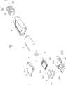
图1是本发明第一实施例线缆连接器组件的立体分解图。FIG. 1 is an exploded perspective view of the cable connector assembly according to the first embodiment of the present invention.
图2图1所示线缆连接器组件的另一视角的立体分解图。FIG. 2 is an exploded perspective view of another viewing angle of the cable connector assembly shown in FIG. 1 .
图3是图1所示线缆连接器组件的部分立体组装图。FIG. 3 is a partial perspective assembly view of the cable connector assembly shown in FIG. 1 .
图4是图1所示线缆连接器组件的另一部分立体组装图。FIG. 4 is another perspective assembly view of the cable connector assembly shown in FIG. 1 .
图5是图1所示线缆连接器组件的又一部分立体组装图。FIG. 5 is another partial perspective assembly view of the cable connector assembly shown in FIG. 1 .
图6是图1所示线缆连接器组件的立体组装图。FIG. 6 is a three-dimensional assembled view of the cable connector assembly shown in FIG. 1 .
图7是本发明第二实施例线缆连接器组件的部分立体组装图。Fig. 7 is a partial perspective assembly view of the cable connector assembly according to the second embodiment of the present invention.
【具体实施方式】【Detailed ways】
请参照图1至图2所示,本发明第一实施例线缆连接器组件100包括连接器1A、与所述连接器1A相连接的线缆组件2B、遮蔽于所述连接器1A外围的遮蔽壳体4及组装于所述连接器1A、遮蔽壳体4及线缆2B外围的外壳体8。1 to 2, the
连接器1A包括有绝缘本体10、设置于绝缘本体10中的导电端子11及与所述导电端子11电性连接的印刷电路板3,所述印刷电路板3共包括有前后两排导电片30,所述前后两排导电片30之间分别设置有复数连接所述前排导电片30和后排导电片30的信号迹线,The
所述信号迹线上设置有电阻32和电容33。所述电阻32和电容33通过并联的方式相连后通过串联的方式与所述导电片30相连。线缆组件2B包括有线缆20及粘贴组装于所述线缆20外围的应力释放元件21。A
遮蔽壳体4包括下壳体40及与所述下壳体40相组装的上壳体41,所述下壳体40包括一前端管状对接部400、与所述管状对接部400的下表面和侧表面相连的U型第一主体部401。所述上壳体41包括与第一主体部401相配合的U型第二主体部411及自所述第二主体部411向后延伸形成的线缆握持部412。所述第二主体部411包括有其位于前端的第一部分413及自所述第一部分413向后延伸形成的第二部分414,所述第二部分414大致呈梯形形状,所述第一部分413的侧壁上设置有与所述第一主体部401的侧壁上形成的锁扣孔402相配合的锁扣片4130。The
所述线缆连接器组件100还包括有设置于所述遮蔽壳体4后端的固持件5,所述固持件5的形状大致与第二部分414相同,在所述下壳体40与上壳体41相组装完成后,将所述固持件5紧贴装设于所述上壳体41的外围,以使得所述固持件5的臂部50紧贴于所述上壳体41的第二部分414的外表面。The
所述线缆连接器组件100还包括有干涉配合于所述外壳体4外表面上的卡扣件6,所述卡扣件6包括有呈圆环状的主体部61及自所述主体部61的后表面向后延伸形成的且其高度低于所述主体部61上下表面的延伸部62,所述主体部61的端口形状与所述绝缘本体10的端口形状相一致,所述卡扣件6自前向后卡扣于所述下壳体40和上壳体41前端相结合的部分,此时,可以观察到,所述位于上侧的延伸部62的下表面紧贴于所述上壳体41的上表面,所述位于下侧的延伸部62的下表面紧贴于所述下壳体40的下表面,藉由此卡扣件6进而将所述下壳体40及上壳体41相互组装于一起。The
请参照图1至图2并结合图3至图6所示,组装时,将所述印刷电路板3组装于所述绝缘本体10的后端以使得组装于所述绝缘本体10中的导电端子11与所述印刷电路板3上的前排导电片30相接触,接着将所述组装有应力释放元件21的线缆20的前端焊接于所述印刷电路板3的后排导电片30的后端上;接着将上述组装好的绝缘本体10和印刷电路板3组装于所述遮蔽壳体4中,此时可以发现,所述绝缘本体10正好组装于所述管状对接部400中,所述印刷电路板3延伸出所述绝缘本体10的后表面的后端设置于所述第一主体部401和第二主体部411所围成的空腔中,将所述内壳体7套设于所述线缆20上位于所述应力释放元件21后方的位置;将所述固持件5成型于所述上壳体41后端及线缆握持件412的前表面之间,此时可以发现,所述固持件5的臂部50紧贴于所述上壳体41的第二部分414的外表面,将所述卡扣件6自前向后卡扣于所述下壳体40和上壳体41的前端衔接部位;再接着将所述内壳体7向前移动组装于所述位于卡扣件6后方的遮蔽壳体4上;最后将所述外壳体8组装于所述组装好的连接器1A、遮蔽壳体4、固持件5、卡扣件6及部分线缆2B的外围,至此,线缆连接器组件100组装完毕。Please refer to Fig. 1 to Fig. 2 in conjunction with Fig. 3 to Fig. 6, when assembling, assemble the printed
请参照图7所示,图7为本发明线缆连接器组件100的另外一种实施例,在图7中的第二实施例线缆连接器组件100’与第一实施例线缆连接器组件100中的区别在于:第二实施例100’中的印刷电路板3’垂直放置,在所述印刷电路板3’上同样设置有电阻及电容,所述电阻和电容的结构及连接方式与第一实施例100中的印刷电路板3上的一样,这里就不再详细描述,需要指出的是,在所述印刷电路板3’上位于所述上排导电片的上方及下排导电片的下方分别设置有一排与所述导电端子11相电性接触的通孔36’。通过将所述印刷电路板3’垂直放置进而进一步降低整个线缆连接器组件100’的整体长度,满足线缆连接器组件结构小型化的要求。Please refer to FIG. 7, which is another embodiment of the
在本发明中,通过在所述印刷电路板3的信号线上设置电阻32及电容33以达到所述线缆连接器组件100在长距离传输中的滤波作用进而防止电磁干扰。In the present invention, a
Claims (10)
Translated fromChinesePriority Applications (1)
| Application Number | Priority Date | Filing Date | Title |
|---|---|---|---|
| CN2010105531649ACN102480078A (en) | 2010-11-22 | 2010-11-22 | Cable connector assembly |
Applications Claiming Priority (1)
| Application Number | Priority Date | Filing Date | Title |
|---|---|---|---|
| CN2010105531649ACN102480078A (en) | 2010-11-22 | 2010-11-22 | Cable connector assembly |
Publications (1)
| Publication Number | Publication Date |
|---|---|
| CN102480078Atrue CN102480078A (en) | 2012-05-30 |
Family
ID=46092612
Family Applications (1)
| Application Number | Title | Priority Date | Filing Date |
|---|---|---|---|
| CN2010105531649APendingCN102480078A (en) | 2010-11-22 | 2010-11-22 | Cable connector assembly |
Country Status (1)
| Country | Link |
|---|---|
| CN (1) | CN102480078A (en) |
Cited By (4)
| Publication number | Priority date | Publication date | Assignee | Title |
|---|---|---|---|---|
| US9437982B2 (en) | 2013-08-12 | 2016-09-06 | Hon Hai Precision Industry Co., Ltd. | Cable connector assembly |
| CN108955469A (en)* | 2018-05-22 | 2018-12-07 | 烽火通信科技股份有限公司 | The contacting travel measurement method of machine disk and the mutual timing of backboard |
| US10622767B2 (en) | 2017-12-19 | 2020-04-14 | Foxconn (Kunshan) Computer Connector Co., Ltd. | Cable connector assembly |
| CN112054322A (en)* | 2020-09-04 | 2020-12-08 | 立讯精密工业股份有限公司 | Connecting structure of cable and PCB, plug assembly adopting connecting structure and preparation method of plug assembly |
Citations (3)
| Publication number | Priority date | Publication date | Assignee | Title |
|---|---|---|---|---|
| WO2008072442A1 (en)* | 2006-12-11 | 2008-06-19 | Autonetworks Technologies, Ltd. | Branch connector |
| CN201138709Y (en)* | 2007-12-18 | 2008-10-22 | 程晓华 | Interference resisting filtering connector |
| CN201282247Y (en)* | 2008-10-14 | 2009-07-29 | 益实实业股份有限公司 | Capacitive electroplate signal adjusting device and connector using same |
- 2010
- 2010-11-22CNCN2010105531649Apatent/CN102480078A/enactivePending
Patent Citations (3)
| Publication number | Priority date | Publication date | Assignee | Title |
|---|---|---|---|---|
| WO2008072442A1 (en)* | 2006-12-11 | 2008-06-19 | Autonetworks Technologies, Ltd. | Branch connector |
| CN201138709Y (en)* | 2007-12-18 | 2008-10-22 | 程晓华 | Interference resisting filtering connector |
| CN201282247Y (en)* | 2008-10-14 | 2009-07-29 | 益实实业股份有限公司 | Capacitive electroplate signal adjusting device and connector using same |
Cited By (5)
| Publication number | Priority date | Publication date | Assignee | Title |
|---|---|---|---|---|
| US9437982B2 (en) | 2013-08-12 | 2016-09-06 | Hon Hai Precision Industry Co., Ltd. | Cable connector assembly |
| US10622767B2 (en) | 2017-12-19 | 2020-04-14 | Foxconn (Kunshan) Computer Connector Co., Ltd. | Cable connector assembly |
| CN108955469A (en)* | 2018-05-22 | 2018-12-07 | 烽火通信科技股份有限公司 | The contacting travel measurement method of machine disk and the mutual timing of backboard |
| CN108955469B (en)* | 2018-05-22 | 2020-05-05 | 烽火通信科技股份有限公司 | Contact stroke measuring method during interaction of machine disc and back plate |
| CN112054322A (en)* | 2020-09-04 | 2020-12-08 | 立讯精密工业股份有限公司 | Connecting structure of cable and PCB, plug assembly adopting connecting structure and preparation method of plug assembly |
Similar Documents
| Publication | Publication Date | Title |
|---|---|---|
| TWI593199B (en) | Electrical connector | |
| CN201230069Y (en) | Electric connector | |
| CN109149277B (en) | Signal connector enabling grounding terminal and grounding piece to jointly form grounding assembly | |
| CN104377510B (en) | Micro coaxial cable connector assembly and its assemble method | |
| CN102412474B (en) | Cable connector component | |
| US20110306244A1 (en) | Cable connector assembly having an adapter plate for grounding | |
| CN201323341Y (en) | Cable connector component | |
| CN102237586B (en) | Electric connector | |
| CN102412456B (en) | electrical connector | |
| CN204597020U (en) | Electric connector combination | |
| TWM501024U (en) | USB socket electrical connector and combination thereof | |
| CN201966371U (en) | Cable connector assembly | |
| US20160240977A1 (en) | Electrical connector and method of making the same | |
| CN101908683B (en) | Electric connector and assembly method thereof | |
| CN204651582U (en) | A kind of electric connector and connector assembly | |
| CN101877448B (en) | Module connector | |
| CN102480078A (en) | Cable connector assembly | |
| TWI550972B (en) | Receptacle connector and electronic device | |
| CN204315764U (en) | Electric connector for socket | |
| CN102117978A (en) | Electric connector | |
| US20030232517A1 (en) | Electrical connector assembly | |
| TWI506865B (en) | Cable connector assembly | |
| CN202633671U (en) | Flexible cable assembly | |
| TWI380540B (en) | Audio plug connector | |
| CN202004177U (en) | Electric connector |
Legal Events
| Date | Code | Title | Description |
|---|---|---|---|
| C06 | Publication | ||
| PB01 | Publication | ||
| C10 | Entry into substantive examination | ||
| SE01 | Entry into force of request for substantive examination | ||
| C02 | Deemed withdrawal of patent application after publication (patent law 2001) | ||
| WD01 | Invention patent application deemed withdrawn after publication | Application publication date:20120530 |