CN102480056B - Base station antenna - Google Patents
Base station antennaDownload PDFInfo
- Publication number
- CN102480056B CN102480056BCN 201110302244CN201110302244ACN102480056BCN 102480056 BCN102480056 BCN 102480056BCN 201110302244CN201110302244CN 201110302244CN 201110302244 ACN201110302244 ACN 201110302244ACN 102480056 BCN102480056 BCN 102480056B
- Authority
- CN
- China
- Prior art keywords
- metamaterial
- coordinate
- refractive index
- metamaterial unit
- area
- Prior art date
- Legal status (The legal status is an assumption and is not a legal conclusion. Google has not performed a legal analysis and makes no representation as to the accuracy of the status listed.)
- Active
Links
Images


Landscapes
- Aerials With Secondary Devices (AREA)
Abstract
Translated fromChinese
Description
Translated fromChinese技术领域technical field
本发明涉及电磁通信领域,更具体地说,涉及一种基站天线。The present invention relates to the field of electromagnetic communication, and more specifically, relates to a base station antenna.
背景技术Background technique
基站天线是保证移动通信终端实现无线接入的重要设备。随着移动通信网络的发展,基站的分布越来越密集,对基站天线的方向性提出了更高的要求,以避免相互干扰,让电磁波传播的更远。The base station antenna is an important device to ensure the wireless access of mobile communication terminals. With the development of mobile communication networks, the distribution of base stations is becoming more and more dense, and higher requirements are placed on the directionality of base station antennas to avoid mutual interference and allow electromagnetic waves to propagate farther.
一般,我们用半功率角来表示基站天线的方向性。功率方向图中,在包含主瓣最大辐射方向的某一平面内,把相对最大辐射方向功率通量密度下降到一半处(或小于最大值3dB)的两点之间的夹角称为半功率角。场强方向图中,在包含主瓣最大辐射方向的某一平面内,把相对最大辐射方向场强下降到0.707倍处的夹角也称为半功率角。半功率角亦称半功率带宽。半功率带宽包括水平面半功率带宽和垂直面半功率带宽。而基站天线的电磁波的传播距离是由垂直面半功率带宽决定的。垂直面半功率带宽越小,基站天线的增益越大,电磁波的传播距离就越远,反之,基站天线的增益就越小,电磁波的传播距离也就越近。Generally, we use the half-power angle to represent the directivity of the base station antenna. In the power pattern diagram, in a certain plane containing the maximum radiation direction of the main lobe, the angle between two points where the relative maximum radiation direction power flux density drops to half (or less than the maximum value 3dB) is called half power horn. In the field strength pattern, in a plane containing the maximum radiation direction of the main lobe, the included angle at which the field strength relative to the maximum radiation direction is reduced to 0.707 times is also called the half-power angle. Half power angle is also called half power bandwidth. Half power bandwidth includes horizontal half power bandwidth and vertical half power bandwidth. The propagation distance of the electromagnetic wave of the base station antenna is determined by the half-power bandwidth of the vertical plane. The smaller the half-power bandwidth of the vertical plane, the greater the gain of the base station antenna, and the farther the propagation distance of electromagnetic waves. Conversely, the smaller the gain of the base station antenna, the closer the propagation distance of electromagnetic waves.
发明内容Contents of the invention
本发明要解决的技术问题在于,提供一种半功率带宽小、方向性好的基站天线。The technical problem to be solved by the present invention is to provide a base station antenna with small half-power bandwidth and good directivity.
本发明解决其技术问题所采用的技术方案是:一种基站天线,包括具有多个呈阵列排布的振子的天线模块及对应这些振子设置的超材料模块,所述超材料模块包括至少一个超材料片层,每个超材料片层由多个超材料单元排列而成;每个超材料片层上正对每个振子的区域形成一个折射率分布区,以每个折射率分布区的一点为原点O、以平行于所述折射率分布区的平面为xoy坐标面建立直角坐标系O-xy;以原点O为中心,在所述折射率分布区上形成多个共中心的方环区域,每一方环区域由x轴和y轴为分界线而将位于所述方环区域内的各个超材料单元分隔在四个子区域内,每个子区域内的各个超材料单元的折射率随着相应超材料单元的x坐标的绝对值的增大而增大、随着相应超材料单元的y坐标的绝对值的增大而减小;对于各个方环区域位于同一象限内的相应子区域,x坐标较大的方环区域内的x坐标最小的各个超材料单元的折射率小于x坐标较小的相邻方环区域内的x坐标最大的各个超材料单元的折射率,或者y坐标较大的方环区域内的y坐标最小的各个超材料单元的折射率大于y坐标较小的相邻方环区域内的y坐标最大的各个超材料单元的折射率。The technical solution adopted by the present invention to solve the technical problem is: a base station antenna, including an antenna module with a plurality of vibrators arranged in an array and a metamaterial module corresponding to these vibrators, the metamaterial module includes at least one super Material sheets, each metamaterial sheet is arranged by a plurality of metamaterial units; each metamaterial sheet is opposite to each vibrator to form a refractive index distribution area, and a point in each refractive index distribution area Establishing a Cartesian coordinate system O-xy as the origin O and a plane parallel to the refractive index distribution area as the xoy coordinate plane; taking the origin O as the center, forming a plurality of concentric square ring regions on the refractive index distribution area , each square ring area uses the x-axis and y-axis as the dividing line to separate the metamaterial units located in the square ring area into four sub-areas, and the refractive index of each meta-material unit in each sub-area increases with the corresponding The absolute value of the x-coordinate of the metamaterial unit increases, and decreases with the increase of the absolute value of the y-coordinate of the corresponding metamaterial unit; The refractive index of each metamaterial unit with the smallest x coordinate in the square ring area with larger coordinates is smaller than the refractive index of each metamaterial unit with the largest x coordinate in the adjacent square ring area with smaller x coordinates, or the y coordinate is larger The refractive index of each metamaterial unit with the smallest y-coordinate in the square ring region is greater than the refractive index of each metamaterial unit with the largest y-coordinate in the adjacent square ring region with smaller y-coordinate.
优选地,每个方环区域内的各个超材料单元的折射率:Preferably, the refractive index of each metamaterial unit in each square ring region:
式中,l为振子到所述折射率分布区的距离;λ为电磁波的波长;d为所述折射率分布区的厚度,
优选地,以经过原点O且垂直于xoy坐标面的直线为z轴,从而建立直角坐标系O-xyz,所述超材料模块包括多个沿z轴叠加的超材料片层,各个超材料片层对应同一振子形成相同的折射率分布区、在相应的折射率分布区内均以同一x轴和y轴为分界线而将位于所述折射率分布区内的超材料单元分隔在四个相同的方环区域内,各个超材料片层上对应同一振子的相应方环区域内的折射率分布规律均相同。Preferably, a straight line passing through the origin O and perpendicular to the xoy coordinate plane is used as the z-axis, thereby establishing a rectangular coordinate system O-xyz, and the metamaterial module includes a plurality of metamaterial sheets stacked along the z axis, each metamaterial sheet The layer corresponds to the same vibrator to form the same refractive index distribution area, and in the corresponding refractive index distribution area, the same x-axis and y-axis are used as the dividing line to separate the metamaterial units located in the refractive index distribution area into four identical In the square ring area of each metamaterial sheet, the refractive index distribution rules in the corresponding square ring area corresponding to the same vibrator are the same.
优选地,各个超材料片层上对应同一振子的相应折射率分布区内的相应超材料单元的折射率均相等。Preferably, the refractive indices of the corresponding metamaterial units in the corresponding refractive index distribution regions corresponding to the same vibrator on each metamaterial sheet are the same.
优选地,位于每个折射率分布区内的各个超材料单元上附着有拓扑形状相同的人工微结构,让位于所述折射率分布区的每个方环区域内的各个超材料单元上排布的所述人工微结构的几何尺寸随着相应超材料单元的x坐标的绝对值的增大而增大、随着相应超材料单元的y坐标的绝对值的增大而减小;而各个方环区域位于同一象限的相应子区域内,x坐标最小的各个超材料单元上排布的所述人工微结构的几何尺寸均相等、x坐标最大的各个超材料单元上排布的所述人工微结构的几何尺寸均相等,或者y坐标最小的各个超材料单元上排布的所述人工微结构的几何尺寸均相等、y坐标最大的各个超材料单元上排布的所述人工微结构的几何尺寸均相等。Preferably, artificial microstructures with the same topological shape are attached to each metamaterial unit located in each refractive index distribution area, allowing rows on each metamaterial unit located in each square ring region of the refractive index distribution area. The geometric size of the artificial microstructure of the cloth increases with the increase of the absolute value of the x-coordinate of the corresponding metamaterial unit, and decreases with the increase of the absolute value of the y-coordinate of the corresponding metamaterial unit; and each The square ring area is located in the corresponding sub-area of the same quadrant, the geometric dimensions of the artificial microstructures arranged on each metamaterial unit with the smallest x coordinate are equal, and the artificial microstructures arranged on each metamaterial unit with the largest x coordinate are The geometric dimensions of the microstructures are all equal, or the geometric dimensions of the artificial microstructures arranged on each metamaterial unit with the smallest y coordinate are all equal, and the artificial microstructures arranged on each metamaterial unit with the largest y coordinate are The geometric dimensions are all equal.
优选地,位于每个折射率分布区内的各个超材料单元上均形成深度相同的圆形小孔,让位于所述折射率分布区的每个方环区域内的各个超材料单元上形成的所述小孔的直径随着相应超材料单元的x坐标的绝对值的增大而减小、随着相应超材料单元的y坐标的绝对值的增大而增大;而各个方环区域位于同一象限的相应子区域内,x坐标最小的各个超材料单元上形成的所述小孔的深度和直径均相等、x坐标最大的各个超材料单元上形成的所述小孔的深度和直径均相等,或者y坐标最小的各个超材料单元上形成的所述小孔的深度和直径均相等、y坐标最大的各个超材料单元上形成的所述小孔的深度和直径均相等。Preferably, circular small holes with the same depth are formed on each metamaterial unit located in each refractive index distribution area, and are formed on each metamaterial unit located in each square ring region of the refractive index distribution area. The diameter of the small hole decreases with the increase of the absolute value of the x-coordinate of the corresponding metamaterial unit, and increases with the increase of the absolute value of the y-coordinate of the corresponding metamaterial unit; and each square ring area Located in the corresponding sub-region of the same quadrant, the depth and diameter of the small hole formed on each metamaterial unit with the smallest x coordinate are equal, and the depth and diameter of the small hole formed on each metamaterial unit with the largest x coordinate or the small holes formed on each metamaterial unit with the smallest y coordinate have the same depth and diameter, and the small holes formed on each metamaterial unit with the largest y coordinate have the same depth and diameter.
优选地,位于每个折射率分布区内的各个超材料单元上均形成直径相同的圆形小孔,让位于所述折射率分布区的每个方环区域内的各个超材料单元上形成的所述小孔的深度随着相应超材料单元的x坐标的绝对值的增大而减小、随着相应超材料单元的y坐标的绝对值的增大而增大;而各个方环区域位于同一象限的相应子区域内,x坐标最小的各个超材料单元上形成的所述小孔的深度和直径均相等、x坐标最大的各个超材料单元上形成的所述小孔的深度和直径均相等,或者y坐标最小的各个超材料单元上形成的所述小孔的深度和直径均相等、y坐标最大的各个超材料单元上形成的所述小孔的深度和直径均相等。Preferably, circular small holes with the same diameter are formed on each metamaterial unit located in each refractive index distribution area, and are formed on each metamaterial unit located in each square ring region of the refractive index distribution area. The depth of the small hole decreases with the increase of the absolute value of the x-coordinate of the corresponding metamaterial unit, and increases with the increase of the absolute value of the y-coordinate of the corresponding metamaterial unit; and each square ring area Located in the corresponding sub-region of the same quadrant, the depth and diameter of the small hole formed on each metamaterial unit with the smallest x coordinate are equal, and the depth and diameter of the small hole formed on each metamaterial unit with the largest x coordinate or the small holes formed on each metamaterial unit with the smallest y coordinate have the same depth and diameter, and the small holes formed on each metamaterial unit with the largest y coordinate have the same depth and diameter.
优选地,位于每个折射率分布区内的各个超材料单元上均形成数量不等的直径和深度均相同的圆形小孔,让位于所述折射率分布区的每个方环区域内的各个超材料单元上形成的所述小孔的个数随着相应超材料单元的x坐标的绝对值的增大而减少、随着相应超材料单元的y坐标的绝对值的增大而增多;而各个方环区域位于同一象限的相应子区域内,x坐标最小的各个超材料单元上形成的所述小孔的数量均相等、x坐标最大的各个超材料单元上形成的所述小孔的数量均相等,或者y坐标最小的各个超材料单元上形成的所述小孔的数量均相等、y坐标最大的各个超材料单元上形成的所述小孔的数量均相等。Preferably, each metamaterial unit located in each refractive index distribution area forms a different number of circular holes with the same diameter and depth, giving way to each square ring area of the refractive index distribution area The number of the small holes formed on each metamaterial unit decreases with the increase of the absolute value of the x coordinate of the corresponding metamaterial unit, and increases with the increase of the absolute value of the y coordinate of the corresponding metamaterial unit ; and each square ring area is located in the corresponding sub-area of the same quadrant, the number of the small holes formed on each metamaterial unit with the smallest x coordinate is equal, and the small holes formed on each metamaterial unit with the largest x coordinate The number of holes is equal, or the number of small holes formed on each metamaterial unit with the smallest y coordinate is equal, and the number of small holes formed on each metamaterial unit with the largest y coordinate is equal.
优选地,所述超材料模块的至少一侧设有阻抗匹配薄膜,每一阻抗匹配薄膜包括多个阻抗匹配层,每一阻抗匹配层是具有单一折射率的均匀介质,各个阻抗匹配层的折射率随着越靠近所述超材料模块由接近于或等于空气的折射率逐渐变化至接近于或等于所述超材料模块上最靠近所述阻抗匹配薄膜的超材料片层的折射率。Preferably, at least one side of the metamaterial module is provided with an impedance matching film, each impedance matching film includes a plurality of impedance matching layers, each impedance matching layer is a homogeneous medium with a single refractive index, and the refraction of each impedance matching layer The refractive index gradually changes from being close to or equal to the refractive index of air to close to or equal to the refractive index of the metamaterial sheet on the metamaterial module closest to the impedance matching film as it gets closer to the metamaterial module.
优选地,各个阻抗匹配层的折射率:式中,m表示每一阻抗匹配薄膜的总层数,i表示阻抗匹配层的序号,最靠近所述超材料模块的阻抗匹配层的序号为m。Preferably, the refractive index of each impedance matching layer: In the formula, m represents the total number of layers of each impedance matching film, i represents the serial number of the impedance matching layer, and the serial number of the impedance matching layer closest to the metamaterial module is m.
本发明的基站天线具有以下有益效果:通过让每个超材料片层对应每个振子形成多个折射率分布区,在每个折射率分布区内形成多个共中心的方环区域,每个方环区域以x轴和y轴为分界线而将其内的各个超材料单元分隔在四个子区域,每个子区域内的各个超材料单元的折射率随着其x坐标的绝对值的增大而增大、随着其y坐标的绝对值的增大而减小,而各个方环区域位于同一象限内的相应子区域,x坐标较大的方环区域内的x坐标最小的各个超材料单元的折射率小于x坐标较小的相邻方环区域区内的x坐标最大的各个超材料单元的折射率,或者y坐标较大的方环区域内的y坐标最小的各个超材料单元的折射率大于y坐标较小的相邻方环区域内的y坐标最大的各个超材料单元的折射率,从而使由振子发射出的电磁波穿过所述超材料模块时向折射率大的方向偏折,以改变电磁波的传播路径,即可减小基站天线的半功率带宽,从而提高了其方向性和增益,让电磁波传播的更远。The base station antenna of the present invention has the following beneficial effects: by allowing each metamaterial sheet to form a plurality of refractive index distribution regions corresponding to each vibrator, a plurality of concentric square ring regions are formed in each refractive index distribution region, and each The square ring area uses the x-axis and y-axis as the dividing line to separate the metamaterial units in four sub-areas, and the refractive index of each meta-material unit in each sub-area increases with the absolute value of its x-coordinate And increase, decrease with the increase of the absolute value of its y coordinate, and each square ring area is located in the corresponding sub-area in the same quadrant, each metamaterial with the smallest x coordinate in the square ring area with larger x coordinate The refractive index of the unit is smaller than the refractive index of each metamaterial unit with the largest x coordinate in the adjacent square ring area with a smaller x coordinate, or the refractive index of each metamaterial unit with the smallest y coordinate in the square ring area with a larger y coordinate The refractive index is greater than the refractive index of each metamaterial unit with the largest y coordinate in the adjacent square ring area with a smaller y coordinate, so that the electromagnetic wave emitted by the vibrator is deflected in the direction of the larger refractive index when passing through the metamaterial module In order to change the propagation path of the electromagnetic wave, the half-power bandwidth of the base station antenna can be reduced, thereby improving its directivity and gain, and allowing the electromagnetic wave to propagate farther.
附图说明Description of drawings
下面将结合附图及具体实施方式对本发明作进一步说明。The present invention will be further described below in conjunction with the accompanying drawings and specific embodiments.
图1是本发明基站天线的结构示意图;Fig. 1 is a schematic structural diagram of a base station antenna of the present invention;
图2是图1中的天线模块的正面放大图;FIG. 2 is an enlarged front view of the antenna module in FIG. 1;
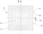
图3是图1中的超材料模块的一个超材料片层的正面放大图,其中对应每个振子形成一折射率分布区;Fig. 3 is a front enlarged view of a metamaterial sheet of the metamaterial module in Fig. 1, wherein a refractive index distribution area is formed corresponding to each vibrator;
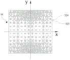
图4是图3中对应一个振子的折射率分布区在建立直角坐标系O-xyz时的示意图;Fig. 4 is a schematic diagram of the refractive index distribution area corresponding to a vibrator in Fig. 3 when the rectangular coordinate system O-xyz is established;
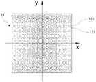
图5是基于图4中的直角坐标系O-xyz于一个折射率分布区内的部分超材料片层上所形成的人工微结构的第一排布示意图;Fig. 5 is a schematic diagram of the first arrangement of artificial microstructures formed on some metamaterial sheets in a refractive index distribution area based on the Cartesian coordinate system O-xyz in Fig. 4;
图6是基于图4中的直角坐标系O-xyz于一个折射率分布区内的部分超材料片层上所形成的人工微结构的第二排布示意图;Fig. 6 is a second schematic diagram of the arrangement of artificial microstructures formed on some metamaterial sheets in a refractive index distribution area based on the Cartesian coordinate system O-xyz in Fig. 4;
图7是基于图4中的直角坐标系O-xyz于一个折射率分布区内的部分超材料片层上所形成的小孔的第一排布示意图;Fig. 7 is based on the Cartesian coordinate system O-xyz in Fig. 4 the first layout schematic diagram of the small holes formed on the partial metamaterial sheet in a refractive index distribution area;
图8是基于图4中的直角坐标系O-xyz于一个折射率分布区内的部分超材料片层上所形成的小孔的第二排布示意图;Fig. 8 is a second schematic diagram of the arrangement of small holes formed on some metamaterial sheets in a refractive index distribution area based on the Cartesian coordinate system O-xyz in Fig. 4;
图9是基于图4中的直角坐标系O-xyz于一个折射率分布区内的部分超材料片层上所形成的小孔的第三排布示意图;Fig. 9 is a third schematic diagram of the arrangement of small holes formed on some metamaterial sheets in a refractive index distribution area based on the Cartesian coordinate system O-xyz in Fig. 4;
图10是基于图4中的直角坐标系O-xyz于一个折射率分布区内的部分超材料片层上所形成的小孔的第四排布示意图;Fig. 10 is a fourth schematic diagram of the arrangement of small holes formed on some metamaterial sheets in a refractive index distribution area based on the Cartesian coordinate system O-xyz in Fig. 4;
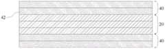
图11是本发明的超材料模块的两侧分别覆盖一阻抗匹配薄膜时的结构示意图。FIG. 11 is a schematic structural view of the metamaterial module of the present invention when both sides are respectively covered with an impedance matching film.
图中各标号对应的名称为:The names corresponding to the labels in the figure are:
10基站天线、12天线模块、14底板、16振子、20超材料模块、22、32超材料片层、222、322基板、223、323超材料单元、224人工微结构、24、34折射率分布区、26、36方环区域、28、38子区域、324小孔、40阻抗匹配薄膜、42阻抗匹配层10 Base Station Antennas, 12 Antenna Modules, 14 Backplanes, 16 Vibrators, 20 Metamaterial Modules, 22, 32 Metamaterial Sheets, 222, 322 Substrates, 223, 323 Metamaterial Units, 224 Artificial Microstructures, 24, 34 Refractive Index Distributions Area, 26, 36 square ring area, 28, 38 sub-areas, 324 small holes, 40 impedance matching film, 42 impedance matching layer
具体实施方式Detailed ways
本发明提供一种基站天线,通过在天线的电磁波发射或接收方向上设置一超材料模块来使半功率带宽变小,以提高其方向性和增益。The invention provides a base station antenna, which reduces the half-power bandwidth by setting a metamaterial module in the direction of electromagnetic wave emission or reception of the antenna, so as to improve its directivity and gain.
我们知道,电磁波由一种均匀介质传播进入另外一种均匀介质时会发生折射,这是由于两种介质的折射率不同而导致的。而对于非均匀介质来说,电磁波在介质内部也会发生折射且向折射率比较大的位置偏折。而折射率等于
超材料是一种以人工微结构为基本单元并以特定方式进行空间排布、具有特殊电磁响应的人工复合材料。一般超材料包括多个超材料片层,每一超材料片层由人工微结构和用于附着人工微结构的基板构成(每个人工微结构及其所附着的基板部分人为定义为一个超材料单元),通过调节人工微结构的拓扑形状和几何尺寸可改变基板上各点(也即各个超材料单元,由于每个超材料单元的尺寸应小于入射电磁波的波长的五分之一,优选为十分之一,一般非常微小,故每个超材料单元可看作一点,下同)的介电常数和磁导率。因此,我们可以利用人工微结构的拓扑形状和/或几何尺寸来调制基板上各点的介电常数和磁导率,从而使基板上各点的折射率以某种规律变化,得以控制电磁波的传播,并应用于具有特殊电磁响应需求的场合。实验证明,在人工微结构的拓扑形状相同的情况下,在单位面积上人工微结构的几何尺寸越大,基板上各点的介电常数越大;反之,介电常数越小。也即,在人工微结构的拓扑形状确定的情况下,可以通过让基板上各点的人工微结构的几何尺寸的大小满足一定的规律来调制其介电常数和磁导率,当用多个这种人工微结构呈一定规律排布的超材料片层叠加在一起形成超材料时,超材料空间各点的折射率也呈这种规律分布,即可达到改变电磁波的传播路径的目的。另外,我们也可在基板上开设小孔来形成这种折射率分布规律。Metamaterial is a kind of artificial composite material with artificial microstructure as the basic unit, which is spatially arranged in a specific way and has special electromagnetic response. A general metamaterial includes a plurality of metamaterial sheets, and each metamaterial sheet is composed of an artificial microstructure and a substrate for attaching the artificial microstructure (each artificial microstructure and its attached substrate are artificially defined as a metamaterial unit), by adjusting the topological shape and geometric size of the artificial microstructure, each point on the substrate (that is, each metamaterial unit, since the size of each metamaterial unit should be less than one-fifth of the wavelength of the incident electromagnetic wave, is preferably One-tenth, generally very small, so each metamaterial unit can be regarded as a point, the same below) permittivity and permeability. Therefore, we can use the topological shape and/or geometric size of the artificial microstructure to modulate the permittivity and magnetic permeability of each point on the substrate, so that the refractive index of each point on the substrate can be changed in a certain order, and the electromagnetic waves can be controlled. Propagation, and applied to occasions with special electromagnetic response requirements. Experiments have proved that in the case of the same topological shape of the artificial microstructure, the larger the geometric size of the artificial microstructure per unit area, the larger the dielectric constant of each point on the substrate; otherwise, the smaller the dielectric constant. That is to say, when the topological shape of the artificial microstructure is determined, the dielectric constant and permeability can be modulated by making the geometric dimensions of the artificial microstructure at each point on the substrate satisfy certain rules. When the metamaterial sheets arranged in a certain order in this artificial microstructure are stacked together to form a metamaterial, the refractive index of each point in the space of the metamaterial also presents such a regular distribution, which can achieve the purpose of changing the propagation path of electromagnetic waves. In addition, we can also open small holes on the substrate to form this refractive index distribution law.
如图1和图2所示,所述基站天线10包括天线模块12和超材料模块20,所述天线模块12包括底板14及阵列排布于所述底板14的振子16,图中所示为每相邻两排振子16相互交错排列的4×9阵列。在其他的实施例中,可以为任何数量的振子16以任意方式排列,如矩阵排布。所述超材料模块20包括多个沿垂直于片层表面的方向(也即基站天线的电磁波发射或接收方向)叠加而成的超材料片层22,图中所示为3个超材料片层22两两相互之间直接前、后表面相粘接在一起的情形。具体实施时,所述超材料片层22的数目可依据需求来增减,各个超材料片层22也可等间距地排列组装在一起。由于各个超材料片层22的折射率分布规律均相同,故在下面仅选取一个超材料片层22作为示例进行说明。As shown in Figures 1 and 2, the
如图3所示,所述超材料片层22上对应每一振子16的位置形成一折射率分布区24。为了示例,图3中由虚线分隔形成了多个相同大小的方形区域来表示折射率分布区24,事实上,所述超材料片层22上对应每一振子16的折射率分布区24可以为任何形状,且各个折射率分布区24的大小也可以不相同。一般,所述超材料片层22包括基板和附着在所述基板上的多个人工微结构或者是形成在所述基板上的多个小孔,由于所述人工微结构和小孔非常微小,在图3中将其近似画作一个点。由于所述超材料片层22上对应每一振子16的位置形成的折射率分布区24内的折射率分布规律均相同,因此我们以下以所述超材料片层22上对应一个振子16的折射率分布区24为例进行说明。As shown in FIG. 3 , a refractive
请参考图4,选取所述折射率分布区24内的一点为原点O,以平行于所述折射率分布区24表面的平面为xoy坐标面、以经过原点O且垂直于xoy坐标面的直线为z轴建立直角坐标系O-xyz。以原点O为中心,在所述折射率分布区24上形成多个共中心的方环区域26,而最小的方环区域26的内环为无穷小,可近似看作一点,也即原点O。每一方环区域26由x轴和y轴为分界线而将其分隔为四个子区域28,每一子区域28内各点的折射率随着其x坐标的绝对值的增大而增大、随着其y坐标的绝对值的增大而减小,优选地,各点的折射率随着其x坐标和y坐标的绝对值的增大而变化量也增大;对于各个方环区域26位于同一象限内的相应子区域28,x坐标较大的方环区域26内的x坐标最小的各点的折射率小于x坐标较小的相邻方环区域26内的x坐标最大的各点的折射率和/或y坐标较大的方环区域26内的y坐标最小的各点的折射率大于y坐标较小的相邻方环区域26内的y坐标最大的各点的折射率。以下介绍一种每个折射率分布区24的各个方环区域26内的x(y)坐标最小的各点的折射率均相等和/或x(y)坐标最大的各点的折射率均相等(也即折射率变化范围相同)的折射率分布规律。Please refer to FIG. 4 , select a point in the refractive
在以上所建立的直角坐标系O-xyz中,对于所述折射率分布区24的每个方环区域26内的各点的折射率满足如下关系式:In the Cartesian coordinate system O-xyz established above, the refractive index of each point in each
式中,l为振子16到所述折射率分布区24表面的距离;λ为电磁波的波长;
要用多个所述超材料片层22来形成所述超材料模块20时,我们可让其沿z轴叠加在一起,并让各个超材料片层22上对应同一振子16形成相同的折射率分布区24;对应同一振子16的各个折射率分布区24形成相同的方环区域26,这些方环区域26均以同一x轴和y轴为分界线而形成四个子区域28,而各个方环区域26的相应子区域28内的折射率分布规律均相同、相应各点的折射率均相等。When
下面我们举例说明如何通过人工微结构的排布来让每个超材料片层22上对应一个振子16的折射率分布区24内的折射率分布满足式(1)。请参考图5,如前所述,每个超材料片层22包括基板222和附着在所述基板222上的多个人工微结构224。所述基板222可由聚四氟乙烯等高分子聚合物或陶瓷材料制成。所述人工微结构224通常为金属线如铜线或者银线构成的具有一定拓扑形状的平面或立体结构,并通过一定的加工工艺附着在所述基板222上,例如蚀刻、电镀、钻刻、光刻、电子刻、离子刻等。一般,我们将每个人工微结构224及其所附着的基板222部分人为定义为一个超材料单元223,且每个超材料单元223的尺寸应小于入射电磁波的波长的五分之一,优选为十分之一,以使所述超材料片层22对入射电磁波产生连续响应。可见,每个超材料片层22可看作是由多个超材料单元223阵列排布而成的。故,对于如上建立了直角坐标系O-xyz的对应一个振子16的折射率分布区24,在xoy坐标面内,我们以原点O为中心,将所述折射率分布区24分隔为若干共中心的方环区域26,则每个方环区域26内的各个超材料单元223以x轴和y轴为分界线而被分隔在四个子区域28内。让具有相同拓扑形状的所述人工微结构224附着在所述折射率分布区24的各个超材料单元223,且每个方环区域26内,各个超材料单元223上排布的所述人工微结构224的几何尺寸随着其x坐标的绝对值的增大而增大、随着其y坐标的绝对值的增大而减小,而各个方环区域26位于同一象限的相应子区域28内,x坐标最小的各个超材料单元223上排布的所述人工微结构224的几何尺寸均相等、x坐标最大的各个超材料单元223上排布的所述人工微结构224的几何尺寸均相等。这样,由于每个子区域28内各个超材料单元223上的所述人工微结构224与基板222的相应部分一起表征了不同的介电常数和磁导率,且各个超材料单元223的介电常数随着其x坐标的绝对值的增大而增大、随着其y坐标的绝对值的增大而减小,而位于同一象限的各个相应子区域28,x坐标最小的各个超材料单元223的介电常数均相等、x坐标最大的各个超材料单元223的介电常数均相等,根据公式折射率
另外,我们也可通过在所述超材料片层22的基板222上开设小孔来形成满足式(1)的折射率分布规律。如图7所示,所述超材料片层32包括基板322和形成在所述基板322上的多个小孔324。所述小孔324可根据所述基板322的材质不同对应采用合适的工艺形成于所述基板322上。例如当所述基板322由高分子聚合物制成时,可通过钻床钻孔、冲压成型或者注塑成型等工艺在所述基板322上形成所述小孔324,而当所述基板322由陶瓷材料制成时则可通过钻床钻孔、冲压成型或者高温烧结等工艺在所述基板322上形成所述小孔324。我们亦将每个小孔324及其所在的基板322部分人为定义为一个超材料单元323,且每个超材料单元323的尺寸应小于入射电磁波的波长的五分之一。这样,所述超材料片层32亦可看作是由多个超材料单元323阵列排布而成的。In addition, we can also form a refractive index distribution law satisfying formula (1) by opening small holes on the
由实验可知,当所述小孔324内填充的介质是空气时,所述小孔324占整个超材料单元323的体积越大,所述超材料单元323的折射率越小。因此,同上,对于建立了直角坐标系O-xyz的对应一个振子16的折射率分布区34,在xoy坐标面内,以原点O为中心,将所述折射率分布区34分隔为若干共中心的方环区域36,而每个方环区域36内的各个超材料单元323以x轴和y轴为分界线被分隔在四个子区域38内。让所述折射率分布区34内的每个超材料单元323上形成一个所述小孔324,在每个方环区域36内,各个超材料单元323上形成的所述小孔324的深度不变而直径随着其x坐标的绝对值的增大而减小、随着其y坐标的绝对值的增大而增大;对于各个方环区域36位于同一象限的相应子区域38内,x坐标最小的各个超材料单元323上形成的所述小孔324的深度和直径均相等、x坐标最大的各个超材料单元323上形成的所述小孔324的深度和直径均相等,从而在所述折射率分布区34的每个方环区域36上形成满足式(1)的折射率分布规律。图7所示仅为对应一个振子16的折射率分布区34内的所述小孔324在部分超材料单元323上的一个排布示意图,其中,每个方环区域36的各个子区域38内的所述小孔324以x轴和y轴对称地排布。此外,对于所述折射率分布区34位于同一象限的相应子区域38,也可让y坐标最小的各个超材料单元323上形成的所述小孔324的深度和直径均相等、y坐标最大的各个超材料单元323上排布的所述小孔324的深度和直径均相等,如图8所示。It can be known from experiments that when the medium filled in the
同理,我们也可让具有相同直径的所述小孔324形成在所述折射率分布区34的各个超材料单元323上,而所述折射率分布区34的每个方环区域36内,各个超材料单元323上所形成的小孔324的深度随着相应超材料单元323的x坐标的绝对值的增大而减小、随着相应超材料单元323的y坐标的绝对值的增大而增大;对于各个方环区域36位于同一象限的相应子区域38,x坐标最小的各个超材料单元323上形成的所述小孔324的深度均相等、x坐标最大的各个超材料单元323上形成的所述小孔324的深度均相等,或者y坐标最小的各个超材料单元323上形成的所述小孔324的深度均相等、y坐标最大的各个超材料单元323上形成的所述小孔324的深度均相等。而且,所述小孔324占整个超材料单元323的体积不仅可通过在所述超材料单元323上形成一个几何尺寸不同的所述小孔324来实现,还可通过在所述超材料单元323上形成数量不等而几何尺寸相同或不相同的所述小孔324来实现,如图9和图10所示。Similarly, we can also let the
要由多个超材料片层22或32形成所述超材料模块20时,让各个超材料片层22或32沿z轴叠加在一起,并让各个超材料片层22或32上对应同一振子16形成相同的折射率分布区24或34及相同的方环区域26或36,相应方环区域26或36内的人工微结构244或小孔324的排布规律均相同,从而使各个所述超材料片层22或32上对应同一振子16的折射率分布区24或34内形成相同的折射率分布规律。When the
由上可知,通过在所述超材料模块20的每个超材料片层22或32上对应每个振子16的位置设置具有一定拓扑形状及/或几何尺寸的人工微结构224或小孔324并让其按照一定的规律排布,且各个超材料片层22或32上对应同一振子16的位置排布的人工微结构224或小孔324具有相同的排布规律,即可得以调制各个超材料单元223或323的介电常数和磁导率,从而在各个超材料片层22或32上对应每个振子16的多个方环区域26或36上形成满足式(1)的折射率分布规律,使电磁波向特定的方向偏折,即可减小基站天线的半功率带宽变小,提高其方向性和增益,让电磁波传播的更远。As can be seen from the above, by setting
此外,由于空气与所述超材料模块20的折射率不同,电磁波入射和出射所述超材料模块20时还会发生反射,这时,我们通常在所述超材料模块20两侧设置阻抗匹配薄膜来减少电磁波反射。如图11所示,所述超材料模块20对应一个振子16的部分两侧分别形成一阻抗匹配薄膜40,每一阻抗匹配薄膜40包括多个压制在一起的阻抗匹配层42,每一阻抗匹配层42是均匀介质,具有单一的折射率,各个阻抗匹配层42具有不同的折射率,且随着越靠近所述超材料模块20其折射率由接近于或等于空气的折射率逐渐变化至接近于或等于所述超材料模块20的最靠近所述阻抗匹配薄膜40的超材料片层22或32的折射率。各个阻抗匹配层42的折射率均满足以下公式:In addition, due to the difference in refractive index between the air and the
式中,m表示所述超材料模块20一侧的阻抗匹配薄膜40的总层数,i表示阻抗匹配层42的序号,最靠近所述超材料模块20的阻抗匹配层42的序号为m。从式(2)可知,每一阻抗匹配层42的总层数m与所述超材料模块20的超材料片层22或32的最大折射率nmax与最小折射率nmin有直接关系;当i=1时,式(5)表示与空气接触的阻抗匹配层42的折射率,其应接近于或等于空气的折射率,可见,只要nmax与nmin确定,就可以确定每一阻抗匹配层42的总层数m。In the formula, m represents the total number of layers of the
各个所述阻抗匹配层42的结构类似于所述超材料片层22或32,分别包括基板和附着在所述基板上的人工微结构或者是形成于所述基板上的小孔,通过调制人工微结构或小孔的几何尺寸和/拓扑形状来使各个阻抗匹配层42的折射率达到所需的要求,从而实现从空气到所述超材料片层22或32的匹配。当然,所述阻抗匹配薄膜40可以是由自然界中存在的多个具有单一折射率的材料制成的。The structure of each of the impedance matching layers 42 is similar to the
所述超材料模块20的两侧分别设置所述阻抗匹配薄膜40时,式(1)中的l为振子16到与其最靠近的阻抗匹配薄膜40表面的距离。When the impedance matching
以上所述仅是本发明的多个具体实施方式和/或实施例,不应当构成对本发明的限制。对于本技术领域的普通技术人员来说,在不脱离本发明基本思想的前提下,还可以做出多个改进和润饰,而这些改进和润饰也应视为本发明的保护范围。比如,式(1)的折射率分布规律还可通过所述人工微结构224或小孔324的拓扑形状或拓扑形状结合几何尺寸来实现,且所述小孔324内也可填充折射率各不相同的介质来改变各个超材料单元323的折射率。The above descriptions are only multiple specific implementations and/or examples of the present invention, and should not be construed as limiting the present invention. For those skilled in the art, many improvements and modifications can be made without departing from the basic idea of the present invention, and these improvements and modifications should also be regarded as the protection scope of the present invention. For example, the refractive index distribution law in formula (1) can also be realized by the topological shape of the
Claims (10)
Translated fromChinese

Priority Applications (1)
| Application Number | Priority Date | Filing Date | Title |
|---|---|---|---|
| CN 201110302244CN102480056B (en) | 2011-09-29 | 2011-09-29 | Base station antenna |
Applications Claiming Priority (1)
| Application Number | Priority Date | Filing Date | Title |
|---|---|---|---|
| CN 201110302244CN102480056B (en) | 2011-09-29 | 2011-09-29 | Base station antenna |
Publications (2)
| Publication Number | Publication Date |
|---|---|
| CN102480056A CN102480056A (en) | 2012-05-30 |
| CN102480056Btrue CN102480056B (en) | 2013-04-24 |
Family
ID=46092593
Family Applications (1)
| Application Number | Title | Priority Date | Filing Date |
|---|---|---|---|
| CN 201110302244ActiveCN102480056B (en) | 2011-09-29 | 2011-09-29 | Base station antenna |
Country Status (1)
| Country | Link |
|---|---|
| CN (1) | CN102480056B (en) |
Families Citing this family (5)
| Publication number | Priority date | Publication date | Assignee | Title |
|---|---|---|---|---|
| CN102820544B (en) | 2012-07-03 | 2015-08-19 | 深圳光启创新技术有限公司 | A kind of antenna reflective face phasing pad pasting and reflector antenna |
| EP2882035B1 (en)* | 2012-08-03 | 2020-04-15 | Kuang-chi Innovative Technology Ltd. | Harmonic oscillator and manufacturing method therefor, filter device and electromagnetic wave equipment |
| CN103001002B (en)* | 2012-11-20 | 2014-04-16 | 深圳光启创新技术有限公司 | Metamaterial and metamaterial design method |
| WO2014079298A1 (en) | 2012-11-20 | 2014-05-30 | 深圳光启创新技术有限公司 | Metamaterial, metamaterial preparation method and metamaterial design method |
| CN108110430A (en)* | 2017-12-18 | 2018-06-01 | 哈尔滨工业大学 | Same polarization vortex beam plane lens based on frequency-selective surfaces |
Citations (3)
| Publication number | Priority date | Publication date | Assignee | Title |
|---|---|---|---|---|
| JP2001085936A (en)* | 1999-09-09 | 2001-03-30 | Matsushita Electric Ind Co Ltd | High frequency substrate, dielectric lens antenna, and method of manufacturing the same |
| CN201450116U (en)* | 2009-07-01 | 2010-05-05 | 东南大学 | Lens antenna with high frequency bandwidth gain and good directivity |
| JP2011112942A (en)* | 2009-11-27 | 2011-06-09 | Toyota Central R&D Labs Inc | Optical deflection element |
Family Cites Families (2)
| Publication number | Priority date | Publication date | Assignee | Title |
|---|---|---|---|---|
| US7570432B1 (en)* | 2008-02-07 | 2009-08-04 | Toyota Motor Engineering & Manufacturing North America, Inc. | Metamaterial gradient index lens |
| US8300294B2 (en)* | 2009-09-18 | 2012-10-30 | Toyota Motor Engineering & Manufacturing North America, Inc. | Planar gradient index optical metamaterials |
- 2011
- 2011-09-29CNCN 201110302244patent/CN102480056B/enactiveActive
Patent Citations (3)
| Publication number | Priority date | Publication date | Assignee | Title |
|---|---|---|---|---|
| JP2001085936A (en)* | 1999-09-09 | 2001-03-30 | Matsushita Electric Ind Co Ltd | High frequency substrate, dielectric lens antenna, and method of manufacturing the same |
| CN201450116U (en)* | 2009-07-01 | 2010-05-05 | 东南大学 | Lens antenna with high frequency bandwidth gain and good directivity |
| JP2011112942A (en)* | 2009-11-27 | 2011-06-09 | Toyota Central R&D Labs Inc | Optical deflection element |
Non-Patent Citations (1)
| Title |
|---|
| 图1A,1B,1C. |
Also Published As
| Publication number | Publication date |
|---|---|
| CN102480056A (en) | 2012-05-30 |
Similar Documents
| Publication | Publication Date | Title |
|---|---|---|
| CN102480044B (en) | Base station antenna | |
| CN102480036A (en) | Base station antenna | |
| CN102480049B (en) | Base station antenna | |
| CN102480056B (en) | Base station antenna | |
| CN102480048A (en) | Base station antenna | |
| CN102480045B (en) | Base station antenna | |
| CN102570044B (en) | base station antenna | |
| CN102480043B (en) | Antenna of base station | |
| CN102480019A (en) | Metamaterial antenna | |
| WO2013016939A1 (en) | Base station antenna | |
| CN102904049B (en) | Base station antenna | |
| CN102480050A (en) | Antenna of base station | |
| CN102904051B (en) | Base station antenna | |
| CN102891370B (en) | Base station antenna | |
| CN103036041B (en) | Base station antenna | |
| CN102810755B (en) | Metamaterial antenna | |
| CN102891371B (en) | Base station antenna | |
| CN102480046A (en) | Base station antenna | |
| CN103094711B (en) | A kind of lens antenna | |
| CN103036040B (en) | Base station antenna | |
| CN102480047A (en) | Base station antenna | |
| CN102904048B (en) | Base station antenna | |
| CN102904050B (en) | Base station antenna | |
| WO2013016940A1 (en) | Base station antenna | |
| CN102800977B (en) | Metamaterial antenna |
Legal Events
| Date | Code | Title | Description |
|---|---|---|---|
| C06 | Publication | ||
| PB01 | Publication | ||
| ASS | Succession or assignment of patent right | Owner name:SHENZHEN KUANG-CHI INNOVATION TECHNOLOGY CO., LTD. Effective date:20120618 | |
| C10 | Entry into substantive examination | ||
| C41 | Transfer of patent application or patent right or utility model | ||
| SE01 | Entry into force of request for substantive examination | ||
| TA01 | Transfer of patent application right | Effective date of registration:20120618 Address after:518000 Nanshan District City, Guangdong province high tech Zone in the middle of a high tech building, No. 9 software building Applicant after:KUANG-CHI INSTITUTE OF ADVANCED TECHNOLOGY Co-applicant after:KUANG-CHI INNOVATIVE TECHNOLOGY Ltd. Address before:518000 Nanshan District City, Guangdong province high tech Zone in the middle of a high tech building, No. 9 software building Applicant before:KUANG-CHI INSTITUTE OF ADVANCED TECHNOLOGY | |
| C14 | Grant of patent or utility model | ||
| GR01 | Patent grant | ||
| ASS | Succession or assignment of patent right | Owner name:SHENZHEN KUANG-CHI INNOVATION TECHNOLOGY CO., LTD. Free format text:FORMER OWNER: SHENZHEN KUANG-CHI INSTITUTE OF ADVANCED TECHNOLOGY Effective date:20140421 Free format text:FORMER OWNER: SHENZHEN KUANG-CHI INNOVATION TECHNOLOGY CO., LTD. Effective date:20140421 | |
| C41 | Transfer of patent application or patent right or utility model | ||
| COR | Change of bibliographic data | Free format text:CORRECT: ADDRESS; FROM: 518000 SHENZHEN, GUANGDONG PROVINCE TO: 518034 SHENZHEN, GUANGDONG PROVINCE | |
| TR01 | Transfer of patent right | Effective date of registration:20140421 Address after:518034 A international business center, No. 1061, Xiang Mei Road, Guangdong, Shenzhen, Futian District, China 18B Patentee after:KUANG-CHI INNOVATIVE TECHNOLOGY Ltd. Address before:518000 Nanshan District City, Guangdong province high tech Zone in the middle of a high tech building, No. 9 software building Patentee before:KUANG-CHI INSTITUTE OF ADVANCED TECHNOLOGY Patentee before:KUANG-CHI INNOVATIVE TECHNOLOGY Ltd. | |
| TR01 | Transfer of patent right | Effective date of registration:20210412 Address after:2 / F, software building, No.9, Gaoxin Zhongyi Road, Nanshan District, Shenzhen City, Guangdong Province Patentee after:KUANG-CHI INSTITUTE OF ADVANCED TECHNOLOGY Address before:18B, building a, CIC international business center, 1061 Xiangmei Road, Futian District, Shenzhen, Guangdong 518034 Patentee before:KUANG-CHI INNOVATIVE TECHNOLOGY Ltd. | |
| TR01 | Transfer of patent right |