CN102480030B - Feed-forward type microwave antenna - Google Patents
Feed-forward type microwave antennaDownload PDFInfo
- Publication number
- CN102480030B CN102480030BCN 201110210400CN201110210400ACN102480030BCN 102480030 BCN102480030 BCN 102480030BCN 201110210400CN201110210400CN 201110210400CN 201110210400 ACN201110210400 ACN 201110210400ACN 102480030 BCN102480030 BCN 102480030B
- Authority
- CN
- China
- Prior art keywords
- metamaterial
- refractive index
- sheet
- graded
- radius
- Prior art date
- Legal status (The legal status is an assumption and is not a legal conclusion. Google has not performed a legal analysis and makes no representation as to the accuracy of the status listed.)
- Active
Links
Images


Landscapes
- Aerials With Secondary Devices (AREA)
Abstract
Translated fromChinese
Description
Translated fromChinese技术领域technical field
本发明涉及天线领域,更具体地说,涉及一种前馈式微波天线。The present invention relates to the field of antennas, in particular to a feedforward microwave antenna.
背景技术Background technique
现有的前馈式微波天线,通常由金属抛物面及位于金属抛物面焦点的辐射源构成,金属抛物面的作用为将外部的电磁波反射给辐射源或将辐射源发射的电磁波反射出去。金属抛物面的面积以及金属抛物面的加工精度直接决定微波天线的各项参数,例如增益、方向性等。Existing feed-forward microwave antennas usually consist of a metal paraboloid and a radiation source located at the focus of the metal parabola. The function of the metal parabola is to reflect external electromagnetic waves to the radiation source or to reflect electromagnetic waves emitted by the radiation source. The area of the metal paraboloid and the machining accuracy of the metal paraboloid directly determine the parameters of the microwave antenna, such as gain and directivity.
但现有的前馈式微波天线存在以下缺点:一是从金属抛物面反射的电磁波部分会被辐射源阻挡造成一定的能量损失,二是金属抛物面制作困难,成本较高。金属抛物面通常利用模具铸造成型或者采用数控机床进行加工的方法。第一种方法的工艺流程包括:制作抛物面模具、铸造成型抛物面和进行抛物反射面的安装。工艺比较复杂,成本高,而且抛物面的形状要比较准确才能实现天线的定向传播,所以对加工精度的要求也比较高。第二种方法采用大型数控机床进行抛物面的加工,通过编辑程序,控制数控机床中刀具所走路径,从而切割出所需的抛物面形状。这种方法切割很精确,但是制造这种大型数控机床比较困难,而且成本比较高。However, the existing feed-forward microwave antenna has the following disadvantages: first, the electromagnetic wave reflected from the metal paraboloid will be blocked by the radiation source, resulting in a certain energy loss; second, the metal paraboloid is difficult to manufacture and the cost is high. Metal paraboloids are usually formed by mold casting or processed by CNC machine tools. The technological process of the first method includes: making a paraboloid mold, casting a paraboloid and installing the paraboloid reflecting surface. The process is relatively complicated, the cost is high, and the shape of the parabola must be relatively accurate to achieve the directional propagation of the antenna, so the requirements for processing accuracy are relatively high. The second method uses a large CNC machine tool to process the paraboloid. By editing the program, the path of the tool in the CNC machine tool is controlled to cut the required paraboloid shape. This method cuts very accurately, but it is difficult to manufacture such a large CNC machine tool, and the cost is relatively high.
发明内容Contents of the invention
本发明要解决的技术问题在于,针对现有技术的上述不足,提供一种体积较小、成本低廉、增益较高且传输距离远的前馈式微波天线。The technical problem to be solved by the present invention is to provide a feed-forward microwave antenna with small volume, low cost, high gain and long transmission distance in view of the above shortcomings of the prior art.
本发明解决其技术问题所采用的技术方案是:提出一种前馈式微波天线,包括:辐射源、用于将所述辐射源发射的电磁波发散的第一超材料面板、第二超材料面板以及贴附于所述第二超材料面板背部的反射面板,电磁波经过所述第一超材料面板被发散后进入所述第二超材料面板产生折射并被所述反射面板反射后再次进入所述第二超材料面板再次发生折射并最终平行出射;所述第一超材料面板包括第一基材及周期排布于所述第一基材上的多个第三人造金属微结构;所述第二超材料面板包括核心层,所述核心层包括多个具有相同折射率分布的核心超材料片层,每一核心超材料片层包括一个圆形区域和与所述圆形区域同心的多个环形区域,所述圆形区域和所述环形区域内折射率变化范围相同,均随着半径的增大从np连续减小到n0且相同半径处的折射率相同;所述核心超材料片层包括核心超材料片层基材及周期排布于所述核心超材料片层基材表面的多个第一人造金属微结构。The technical solution adopted by the present invention to solve the technical problem is: to propose a feed-forward microwave antenna, comprising: a radiation source, a first metamaterial panel and a second metamaterial panel for diverging electromagnetic waves emitted by the radiation source And a reflective panel attached to the back of the second metamaterial panel, the electromagnetic wave is diverged through the first metamaterial panel and then enters the second metamaterial panel for refraction and is reflected by the reflective panel and then enters the second metamaterial panel again The second metamaterial panel refracts again and finally emits in parallel; the first metamaterial panel includes a first base material and a plurality of third artificial metal microstructures periodically arranged on the first base material; The second metamaterial panel comprises a core layer comprising a plurality of core metamaterial sheets having the same refractive index distribution, each core metamaterial sheet comprising a circular region and a plurality of Annular area, the range of refractive index variation in the circular area and the annular area is the same, all decrease continuously fromnp ton0 with the increase of radius and the refractive index at the same radius is the same; the core metamaterial The sheet includes a core metamaterial sheet substrate and a plurality of first artificial metal microstructures periodically arranged on the surface of the core metamaterial sheet substrate.
进一步地,所述第二超材料面板还包括对称设置于所述核心层两侧的第一渐变超材料片层至第N渐变超材料片层,其中对称设置的两层第N渐变超材料片层均靠近所述核心层;每一渐变超材料片层均包括一个圆形区域和与所述圆形区域同心的多个环形区域,每一渐变超材料片层对应的所述圆形区域和所述环形区域内的折射率变化范围均相同且随着半径的增大从其最大折射率连续减小到n0,相同半径处的折射率相同,两个相邻的渐变超材料片层的最大折射率表示为ni和ni+1,其中n0<ni<ni+1<np,i为正整数,ni对应于距离所述核心层较远的渐变超材料片层的最大折射率值;所述每一渐变超材料片层包括渐变超材料片层基材以及周期排布于所述渐变超材料片层基材表面的多个第二人造金属微结构;全部的渐变超材料片层和全部的核心超材料片层构成了所述第二超材料面板的功能层。Further, the second metamaterial panel also includes the first graded metamaterial sheet to the Nth graded metamaterial sheet symmetrically arranged on both sides of the core layer, wherein the two symmetrically arranged Nth graded metamaterial sheets The layers are all close to the core layer; each gradient metamaterial sheet layer includes a circular area and a plurality of annular areas concentric with the circular area, and the corresponding circular area and the circular area of each gradient metamaterial sheet layer The range of refractive index variation in the annular region is the same and decreases continuously from the maximum refractive index to n0 with the increase of the radius, the refractive index at the same radius is the same, the two adjacent graded metamaterial sheets The maximum refractive index is expressed as ni and ni+1 , where n0 <ni <ni+1 <np , i is a positive integer, and ni corresponds to the gradient metamaterial sheet farther away from the core layer The maximum refractive index value; each graded metamaterial sheet includes a graded metamaterial sheet substrate and a plurality of second artificial metal microstructures periodically arranged on the surface of the graded metamaterial sheet substrate; all The graded metamaterial sheet and all the core metamaterial sheets constitute the functional layer of the second metamaterial panel.
进一步地,所述第二超材料面板还包括对称设置于所述功能层两侧的第一匹配层至第M匹配层,其中对称设置的两层第M匹配层均靠近所述第一渐变超材料片层;每一匹配层折射率分布均匀,靠近自由空间的所述第一匹配层折射率大致等于自由空间折射率,靠近所述第一渐变超材料片层的第M匹配层折射率大致等于所述第一渐变超材料片层最小折射率n0。Further, the second metamaterial panel also includes the first matching layer to the Mth matching layer symmetrically arranged on both sides of the functional layer, wherein the two symmetrically arranged Mth matching layers are close to the first gradient superstructure Material sheets; the refractive index distribution of each matching layer is uniform, the refractive index of the first matching layer close to the free space is approximately equal to the free space refractive index, and the refractive index of the Mth matching layer close to the first graded metamaterial sheet is approximately equal to the minimum refractive index n0 of the first graded metamaterial sheet.
进一步地,所有渐变超材料片层与所有核心超材料片层上被划分的圆形区域和与圆形区域同心的环形区域的起始半径和终止半径均相等;每一渐变超材料片层和所有核心超材料片层随着半径r的变化,折射率分布关系式为:Further, all graded metamaterial sheets and all core metamaterial sheets are divided into circular regions and the starting radius and the ending radius of the circular region concentric with the circular region are equal; each graded metamaterial sheet and All the core metamaterial sheets change with the radius r, and the refractive index distribution relation is:
其中,第一渐变超材料片层至第N渐变超材料片层对应的i值即为数值一至N,所有的核心超材料片层对应的i值均为N+1,s为所述辐射源距所述第一渐变超材料片层的垂直距离;d为第一渐变超材料片层至第N渐变超材料片层与所有的核心超材料片层所具有的总厚度,
进一步地,所述核心超材料片层为三层,每层核心超材料片层还包括覆盖于所述第一人造金属微结构上的覆盖层;周期排布于所述基材上的多个所述第一人造金属微结构的尺寸变化规律为:多个所述第一人造金属微结构的几何形状相同,所述基材包括圆形区域以及与所述圆形区域同心的多个环形区域,所述圆形区域和所述环形区域内第一人造金属微结构尺寸变化范围相同,均随着半径的增大从最大尺寸连续减小到最小尺寸且相同半径处的第一人造金属微结构尺寸相同。Further, the core metamaterial sheet has three layers, and each layer of core metamaterial sheet also includes a cover layer covering the first artificial metal microstructure; a plurality of layers periodically arranged on the substrate The dimensional change law of the first artificial metal microstructure is as follows: a plurality of the first artificial metal microstructures have the same geometric shape, and the substrate includes a circular area and a plurality of annular areas concentric with the circular area , the size variation range of the first artificial metal microstructure in the circular area and the annular area is the same, both continuously decrease from the largest size to the smallest size with the increase of the radius, and the first artificial metal microstructure at the same radius Same size.
进一步地,所述核心层两侧对称设置有第一渐变超材料片层至第三渐变超材料片层,每层渐变超材料片层还包括覆盖于所述第二人造金属微结构上的覆盖层;周期排布于所述基材上的所述第二人造金属微结构的尺寸变化规律为:多个所述第二人造金属微结构的几何形状相同,所述基材包括圆形区域以及与所述圆形区域同心的多个环形区域,所述圆形区域和所述环形区域内第二人造金属微结构尺寸变化范围相同,均随着半径的增大从最大尺寸连续减小到最小尺寸且相同半径处的第二人造金属微结构尺寸相同。Further, the first to third graded metamaterial sheets are arranged symmetrically on both sides of the core layer, and each layer of graded metamaterial sheets also includes a cover covering the second artificial metal microstructure. layer; the dimensional change law of the second artificial metal microstructures periodically arranged on the substrate is: a plurality of the second artificial metal microstructures have the same geometric shape, and the substrate includes a circular area and A plurality of annular regions concentric with the circular region, the size variation range of the second artificial metal microstructure in the circular region and the annular region is the same, and they all continuously decrease from the largest size to the smallest as the radius increases The size and the second artificial metal microstructures at the same radius have the same size.
进一步地,所述第一超材料面板折射率呈圆形分布,圆心处的折射率最小且随着半径的增大,对应半径的折射率亦增大且相同半径处折射率相同。Further, the refractive index of the first metamaterial panel has a circular distribution, and the refractive index at the center of the circle is the smallest. As the radius increases, the refractive index corresponding to the radius also increases, and the refractive index at the same radius is the same.
进一步地,所述第一超材料面板由多个折射率分布相同的第一超材料片层构成,所述第一超材料片层还包括覆盖于所述第三人造微结构上的覆盖层;多个第三人造微结构为第三人造金属微结构且几何形状相同,所述第三人造金属微结构在所述第一基材上呈圆形分布,且圆心处的第三人造金属微结构尺寸最小,随着半径的增大,对应半径的第三人造金属微结构尺寸亦增大且相同半径处的第三人造金属微结构尺寸相同。Further, the first metamaterial panel is composed of a plurality of first metamaterial sheets with the same refractive index distribution, and the first metamaterial sheet also includes a covering layer covering the third artificial microstructure; A plurality of third artificial microstructures are third artificial metal microstructures with the same geometric shape, the third artificial metal microstructures are distributed in a circle on the first substrate, and the third artificial metal microstructures at the center of the circle The size is the smallest, and as the radius increases, the size of the third artificial metal microstructure corresponding to the radius also increases, and the third artificial metal microstructure at the same radius has the same size.
进一步地,所述多个第一人造金属微结构、所述多个第二人造金属微结构和所述多个第三人造金属结构具有相同的几何形状。Further, the plurality of first artificial metal microstructures, the plurality of second artificial metal microstructures and the plurality of third artificial metal structures have the same geometry.
进一步地,所述几何形状为“工”字形,包括竖直的第一金属分支以及位于所述第一金属分支两端且垂直于所述第一金属分支的第二金属分支。Further, the geometric shape is an "I" shape, including a vertical first metal branch and a second metal branch located at both ends of the first metal branch and perpendicular to the first metal branch.
进一步地,所述几何形状还包括位于所述第二金属分支两端且垂直于所述第二金属分支的第三金属分支。Further, the geometric shape further includes a third metal branch located at both ends of the second metal branch and perpendicular to the second metal branch.
进一步地,所述几何形状为平面雪花型,包括相互垂直的两条第一金属分支以及位于所述第一金属分支两端且垂直于所述第一金属分支的第二金属分支。Further, the geometric shape is a plane snowflake, including two first metal branches perpendicular to each other and second metal branches located at both ends of the first metal branches and perpendicular to the first metal branches.
实施本发明的技术方案,具有以下有益效果:通过设计超材料面板核心层和渐变层上及各自之间的折射率变化将辐射源发射的电磁波经过两次折射后转换为平面波,从而提高了天线的汇聚性能,大大减少了反射损耗,也就避免了电磁能量的减少,增强了传输距离,提高了天线性能。进一步地,本发明还在辐射源前端设置具有发散功能的超材料,从而提高辐射源的近距离辐射范围,使得微波天线整体能够更小的尺寸并使得被核心层反射回来的电磁波绕过辐射源而不会产生辐射源阴影、造成能量损失。Implementing the technical solution of the present invention has the following beneficial effects: by designing the refractive index changes on and between the core layer and the gradient layer of the metamaterial panel, the electromagnetic wave emitted by the radiation source is converted into a plane wave after twice refraction, thereby improving the performance of the antenna. The convergence performance greatly reduces the reflection loss, avoids the reduction of electromagnetic energy, enhances the transmission distance, and improves the antenna performance. Further, the present invention also sets a metamaterial with a divergence function at the front end of the radiation source, thereby improving the short-distance radiation range of the radiation source, making the overall size of the microwave antenna smaller and allowing the electromagnetic waves reflected back by the core layer to bypass the radiation source It will not produce radiation source shadows and cause energy loss.
附图说明Description of drawings
下面将结合附图及实施例对本发明作进一步说明,附图中:The present invention will be further described below in conjunction with accompanying drawing and embodiment, in the accompanying drawing:
图1是构成超材料的基本单元的立体结构示意图;Figure 1 is a schematic diagram of the three-dimensional structure of the basic unit constituting the metamaterial;
图2是本发明前馈式微波天线的结构示意图;Fig. 2 is the structural representation of feed-forward microwave antenna of the present invention;
图3是本发明前馈式微波天线中构成第一超材料面板的第一超材料片层的结构示意图;Fig. 3 is a structural schematic diagram of the first metamaterial sheet constituting the first metamaterial panel in the feedforward microwave antenna of the present invention;
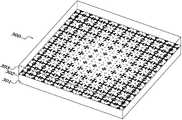
图4是本发明前馈式微波天线中第二超材料面板的立体结构示意图;Fig. 4 is the schematic diagram of the three-dimensional structure of the second metamaterial panel in the feedforward microwave antenna of the present invention;
图5是本发明前馈式微波天线中第二超材料面板上核心层随半径变化的折射率分布示意图;Fig. 5 is a schematic diagram of the refractive index distribution of the core layer on the second metamaterial panel as the radius changes in the feedforward microwave antenna of the present invention;
图6是能对电磁波产生响应以改变超材料基本单元折射率的第一较佳实施方式的人造金属微结构的几何形状拓扑图案;Fig. 6 is the geometric topological pattern of the artificial metal microstructure of the first preferred embodiment that can respond to electromagnetic waves to change the refractive index of the basic unit of the metamaterial;
图6a为图6中人造金属微结构几何形状拓扑图案的衍生图案;Figure 6a is a derivative pattern of the geometric topological pattern of the artificial metal microstructure in Figure 6;
图7是能对电磁波产生响应以改变超材料基本单元折射率的第二较佳实施方式的人造金属微结构的几何形状拓扑图案;Fig. 7 is the geometric topological pattern of the artificial metal microstructure of the second preferred embodiment that can respond to electromagnetic waves to change the refractive index of the basic unit of the metamaterial;
图7a为图7中人造金属微结构几何形状拓扑图案的衍生图案。Fig. 7a is a derivative pattern of the geometric topological pattern of the artificial metal microstructure in Fig. 7.
具体实施方式Detailed ways
光,作为电磁波的一种,其在穿过玻璃的时候,因为光线的波长远大于原子的尺寸,因此我们可以用玻璃的整体参数,例如折射率,而不是组成玻璃的原子的细节参数来描述玻璃对光线的响应。相应的,在研究材料对其他电磁波响应的时候,材料中任何尺度远小于电磁波波长的结构对电磁波的响应也可以用材料的整体参数,例如介电常数ε和磁导率μ来描述。通过设计材料每点的结构使得材料各点的介电常数和磁导率都相同或者不同从而使得材料整体的介电常数和磁导率呈一定规律排布,规律排布的磁导率和介电常数即可使得材料对电磁波具有宏观上的响应,例如汇聚电磁波、发散电磁波等。该类具有规律排布的磁导率和介电常数的材料我们称之为超材料。Light, as a kind of electromagnetic wave, when it passes through glass, because the wavelength of light is much larger than the size of atoms, we can use the overall parameters of the glass, such as the refractive index, rather than the detailed parameters of the atoms that make up the glass to describe The response of glass to light. Correspondingly, when studying the response of materials to other electromagnetic waves, the response of any structure in the material whose scale is much smaller than the wavelength of the electromagnetic wave to electromagnetic waves can also be described by the overall parameters of the material, such as the dielectric constant ε and magnetic permeability μ. By designing the structure of each point of the material, the dielectric constant and magnetic permeability of each point of the material are the same or different, so that the overall dielectric constant and magnetic permeability of the material are arranged in a certain order, and the regularly arranged magnetic permeability and magnetic permeability The electrical constant can make the material have a macroscopic response to electromagnetic waves, such as converging electromagnetic waves and diverging electromagnetic waves. Such materials with regularly arranged magnetic permeability and permittivity are called metamaterials.
如图1所示,图1为构成超材料的基本单元的立体结构示意图。超材料的基本单元包括人造微结构1以及该人造微结构附着的基材2。本发明中,人造微结构为人造金属微结构,人造金属微结构具有能对入射电磁波电场和/或磁场产生响应的平面或立体拓扑结构,改变每个超材料基本单元上的人造金属微结构的图案和/或尺寸即可改变每个超材料基本单元对入射电磁波的响应。多个超材料基本单元按一定规律排列即可使得超材料对电磁波具有宏观的响应。由于超材料整体需对入射电磁波有宏观电磁响应因此各个超材料基本单元对入射电磁波的响应需形成连续响应,这要求每一超材料基本单元的尺寸为入射电磁波的十分之一至五分之一,优选为入射电磁波的十分之一。本段描述中,我们人为的将超材料整体划分为多个超材料基本单元,但应知此种划分方法仅为描述方便,不应看成超材料由多个超材料基本单元拼接或组装而成,实际应用中超材料是将人造金属微结构周期排布于基材上即可构成,工艺简单且成本低廉。周期排布即指上述我们人为划分的各个超材料基本单元上的人造金属微结构能对入射电磁波产生连续的电磁响应。As shown in FIG. 1 , FIG. 1 is a schematic diagram of a three-dimensional structure of a basic unit constituting a metamaterial. The basic unit of a metamaterial includes an artificial microstructure 1 and a
如图2所示,图2为本发明前馈式微波天线的结构示意图。图2中,本发明前馈式微波天线包括辐射源20、第一超材料面板30、第二超材料面板10以及位于第二超材料面板10背部的反射面板40。本发明中,辐射源20发射的电磁波频率为12.4G赫兹至18G赫兹。As shown in FIG. 2 , FIG. 2 is a schematic structural diagram of the feedforward microwave antenna of the present invention. In FIG. 2 , the feedforward microwave antenna of the present invention includes a
第一超材料面板30可直接贴附于辐射源20的辐射端口上,但是,当第一超材料面板30直接贴附于辐射源20的辐射端口上时辐射源20辐射的电磁波部分会被第一超材料面板30反射造成能量损失,因此本发明中,第一超材料面板30设置于辐射源20前方。第一超材料面板30由多片折射率分布相同的第一超材料片层300构成,如图3所示,图3为第一超材料片层300的立体结构示意图,为清楚介绍第一超材料片层300,图3采用透视图画法,第一超材料片层300包括第一基材301以及周期排布于第一基材上的多个第三人造金属微结构302,优选地,在多个第三人造金属微结构302上还覆盖有覆盖层303使得第三人造金属微结构302被封装,覆盖层303与第一基材材质302相等且厚度相等。本发明中,覆盖层303与第一基材302的厚度均为0.4毫米,而人造金属微结构层的厚度为0.018毫米,因此整个第一超材料片层的厚度为0.818毫米。The
构成第一超材料片层300的基本单元仍如图1所示,但第一超材料片层300需具有发散电磁波的功能,根据电磁学原理,电磁波向折射率大的方向偏折。因此,第一超材料片层300上的折射率变化规律为:第一超材料片层300折射率呈圆形分布,圆心处的折射率最小且随着半径的增大,对应半径的折射率亦增大且相同半径处折射率相同。具有该类折射率分布的第一超材料片层300使得辐射源20辐射出来的电磁波被发散,从而提高辐射源的近距离辐射范围,使得微波天线整体能够更小的尺寸,并能使得被反射面反射出来的电磁波不被辐射源挡住。The basic units constituting the
更具体地,本发明中,第一超材料片层300上的折射率分布规律可以为线性变化,即n(R)=nmin+KR,K为常数,R为圆形分布的第三人造金属微结构附着的超材料基本单元中心点与第一基材中心点的连线距离,nmin为第一基材中心点所具有的折射率值。另外,第一超材料片层300上的折射率分布规律亦可为平方率变化,即n(R)=nmin+KR2;或为立方率变化即n(R)=nmin+KR3;或为冥函数变化,即n(R)=nmin*KR等。由上述第一超材料片层300的变化公式可知,只要第一超材料片层300满足发散辐射源发射的电磁波即可。More specifically, in the present invention, the refractive index distribution law on the
下面详细描述本发明微波天线第二超材料面板。被第一超材料面板发散的电磁波进入第二超材料面板后发生折射并被反射面板反射,反射的电磁波再次进入第二超材料面板再次发生折射后使得发散的球面电磁波以更适于远距离传输的平面电磁波辐射出去。如图4所示,图4为本发明第二超材料面板和反射面板的立体结构示意图。图4中,第二超材料面板10包括核心层,该核心层由多个折射率分布相同的核心超材料片层11构成;设置于核心层前侧的第一渐变超材料片层101至第N渐变超材料片层,本实施例中渐变超材料片层为第一渐变超材料片层101、第二渐变超材料片层102以及第三渐变超材料片层103;设置于第一渐变超材料片层101前侧的第一匹配层111至第M匹配层,每一匹配层折射率分布均匀且靠近自由空间的第一匹配层111折射率大致等于自由空间折射率,靠近第一渐变超材料片层的最后一层匹配层折射率大致等于该第一渐变超材料片层101最小的折射率;本实施例中匹配层包括第一匹配层111、第二匹配层112以及第三匹配层113。渐变超材料片层与匹配层均具有减少电磁波的反射,并起到阻抗匹配和相位补偿的作用,因此设置渐变超材料片层和匹配层是较优选的实施方式。The second metamaterial panel of the microwave antenna of the present invention will be described in detail below. The electromagnetic wave diverged by the first metamaterial panel enters the second metamaterial panel and is refracted and reflected by the reflective panel. The reflected electromagnetic wave enters the second metamaterial panel again and is refracted again so that the divergent spherical electromagnetic wave is more suitable for long-distance transmission. The plane electromagnetic wave radiates out. As shown in FIG. 4 , FIG. 4 is a schematic perspective view of the three-dimensional structure of the second metamaterial panel and the reflective panel of the present invention. In Fig. 4, the
匹配层结构与第一超材料片层类似,由覆盖层和基材构成,与第一超材料片层不同之处在于,覆盖层和基材中间全部填充有空气,通过改变覆盖层与基材的间距以改变空气的占空比从而使得各匹配层具有不同的折射率。The structure of the matching layer is similar to that of the first metamaterial sheet, consisting of a covering layer and a substrate. The difference from the first metamaterial sheet is that the middle of the covering layer and the substrate is filled with air. By changing the covering layer and the substrate The distance between them is changed to change the duty cycle of the air so that each matching layer has a different refractive index.
构成核心超材料片层和渐变超材料片层的基本单元均如图1所示,且本发明中,为简化制作工艺,核心超材料片层和渐变超材料片层的尺寸结构与第一超材料片层相同,即均由0.4毫米的覆盖层、0.4毫米的基材以及0.018毫米的人造金属微结构构成各核心超材料片层与各渐变超材料片层。同时,本发明中,分别构成核心超材料片层、渐变超材料片层与第一超材料片层的第一人造金属微结构、第二人造金属微结构与第三人造金属微结构的几何形状均相同。The basic units constituting the core metamaterial sheet and the gradient metamaterial sheet are all as shown in Figure 1, and in the present invention, in order to simplify the manufacturing process, the size structure of the core metamaterial sheet and the gradient metamaterial sheet is the same as that of the first supermaterial sheet. The material sheets are the same, that is, each core metamaterial sheet and each gradient metamaterial sheet are composed of a 0.4 mm covering layer, a 0.4 mm substrate, and a 0.018 mm artificial metal microstructure. At the same time, in the present invention, the geometric shapes of the first artificial metal microstructure, the second artificial metal microstructure and the third artificial metal microstructure constituting the core metamaterial sheet, the gradient metamaterial sheet and the first metamaterial sheet respectively are the same.
核心超材料片层和渐变超材料片层均被划分为一个圆形区域和与所述圆形区域同心的多个环形区域,且圆形区域和环形区域内的折射率均随着半径的增大从各片层所具有的最大折射率连续减小到n0,处于相同半径的超材料基本单元的折射率值相同。其中核心超材料片层具有的最大折射率为np,两个相邻的渐变超材料片层的最大折射率为ni和ni+1,ni对应于距离所述核心层较远的渐变超材料片层,np、n0、ni、ni+1满足关系式n0<ni<ni+1<np。由核心超材料片层和渐变超材料片层构成的功能层的具体每一层上具有相同半径r的超材料基本单元的折射率分布满足:Both the core metamaterial sheet and the gradient metamaterial sheet are divided into a circular area and multiple annular areas concentric with the circular area, and the refractive index in the circular area and the annular area increases with the increase of the radius The maximum refractive index of each sheet layer decreases continuously to n0 , and the refractive index values of the metamaterial basic units at the same radius are the same. Wherein the core metamaterial sheet has a maximum refractive index np , and the maximum refractive indices of two adjacent graded metamaterial sheets areni andni+1 , whereni corresponds to the For the graded metamaterial sheet, np , n0 ,ni , and ni+1 satisfy the relationship n0 <ni <ni+1 <np . The refractive index distribution of the metamaterial basic unit with the same radius r on each layer of the functional layer composed of the core metamaterial sheet and the gradient metamaterial sheet satisfies:
其中,第一渐变超材料片层至第N渐变超材料片层对应的i值即为数值一至N,所有的核心层对应的i值均为N+1,s为所述辐射源距所述第一渐变超材料片层的垂直距离,d为第一渐变超材料片层至第N渐变超材料片层与所有的核心超材料片层所具有的总厚度,
下面论述较佳的L(j)的确定方法,从辐射源辐射的电磁波入射进入第一渐变超材料片层时,由于不同的出射角度使得入射到第一渐变超材料片层的电磁波经过的光程不相等,s为辐射源距第一渐变超材料片层的垂直距离也是入射到第一渐变超材料片层的电磁波所经过的最短光程,此时,该入射点即对应第一渐变超材料片层的圆形区域起始半径,即j=1时对应的L(1)=0。当辐射源发出的某束电磁波入射到第一渐变超材料片层时,其经过的光程为s+λ时,该束电磁波的入射点与垂直入射时入射点的距离即为多个环形区域的第一环形区域的起始半径亦为圆形区域的终止半径,根据数学公式可知,j=2时,对应的
为了更直观表示上述变化规律,图5给出了核心层随半径变化的折射率示意图。图5中,每个区域的折射率均由np逐渐变化到n0,各个区域的起始半径和终止半径根据上述L(j)的关系式给出。图5仅给出了三个区域即L(2)至L(4)的区域变化范围,但应知其仅为示意性的,实际应用中可根据需要应用上述L(j)的推导得出任意区域的起始和终止半径。渐变层折射率随半径变化的折射率示意图与图5类似,不同之处仅在于其最大值不为np,而是其自身的折射率最大值。In order to more intuitively represent the above variation law, Fig. 5 shows a schematic diagram of the refractive index of the core layer changing with the radius. In Fig. 5, the refractive index of each region changes gradually from np to n0 , and the starting radius and ending radius of each region are given according to the above-mentioned relational expression of L(j). Figure 5 only shows the change range of the three regions, namely L(2) to L(4), but it should be known that it is only for illustration, and the derivation of the above L(j) can be obtained according to the actual application. The start and end radii of any area. The schematic diagram of the refractive index of the graded layer changing with the radius is similar to that in Fig. 5, except that its maximum value is not np , but its own maximum value of the refractive index.
上面详细论述了第一超材料面板和第二超材料面板的整体折射率分布关系,由超材料原理可知,基材上附着的人造金属微结构的尺寸和图案直接决定超材料各点的折射率值。同时,根据实验可知,相同几何形状的人造金属微结构其尺寸越大时,对应的超材料基本单元折射率越大。本发明中,由于多个第一人造金属微结构、多个第二人造金属微结构、多个第三人造金属微结构几何形状均相同,因此构成第一超材料面板的第一超材料片层上的第三人造金属微结构排布规律为:多个第三人造微结构为第三人造金属微结构且几何形状相同,所述第三人造金属微结构在所述第一基材上呈圆形分布,且圆心处的第三人造金属微结构尺寸最小,随着半径的增大,对应半径的第三人造金属微结构尺寸亦增大且相同半径处的第三人造金属微结构尺寸相同。渐变超材料片层上的第二人造金属微结构排布规律为:多个第二人造金属微结构的几何形状相同,渐变超材料片层的基材包括圆形区域以及与所述圆形区域同心的多个环形区域,所述圆形区域和所述环形区域内第二人造金属微结构尺寸变化范围相同,均随着半径的增大从最大尺寸连续减小到最小尺寸且相同半径处的第二人造金属微结构尺寸相同。核心超材料片层上的第一人造金属微结构排布规律为:多个第一人造金属微结构的几何形状相同,核心超材料片层的基材包括圆形区域以及与所述圆形区域同心的多个环形区域,所述圆形区域和所述环形区域内第一人造金属微结构尺寸变化范围相同,均随着半径的增大从最大尺寸连续减小到最小尺寸且相同半径处的第一人造金属微结构尺寸相同。The overall refractive index distribution relationship between the first metamaterial panel and the second metamaterial panel has been discussed in detail above. According to the principle of metamaterials, the size and pattern of the artificial metal microstructure attached to the substrate directly determine the refractive index of each point of the metamaterial. value. At the same time, according to experiments, the larger the size of the artificial metal microstructure with the same geometric shape, the larger the refractive index of the corresponding metamaterial basic unit. In the present invention, since a plurality of first artificial metal microstructures, a plurality of second artificial metal microstructures, and a plurality of third artificial metal microstructures have the same geometric shapes, the first metamaterial sheet constituting the first metamaterial panel The arrangement rule of the third artificial metal microstructures on the substrate is as follows: multiple third artificial microstructures are third artificial metal microstructures with the same geometric shape, and the third artificial metal microstructures are circular on the first substrate. distribution, and the size of the third artificial metal microstructure at the center of the circle is the smallest, as the radius increases, the size of the third artificial metal microstructure corresponding to the radius also increases, and the third artificial metal microstructure at the same radius has the same size. The arrangement rule of the second artificial metal microstructure on the gradient metamaterial sheet is as follows: the geometry of multiple second artificial metal microstructures is the same, and the base material of the gradient metamaterial sheet includes a circular area and the circular area. A plurality of concentric annular areas, the circular area and the second artificial metal microstructure in the annular area have the same size variation range, and they all decrease continuously from the largest size to the smallest size with the increase of the radius and at the same radius The second artificial metal microstructures are of the same size. The arrangement rule of the first artificial metal microstructures on the core metamaterial sheet is: the geometric shapes of multiple first artificial metal microstructures are the same, and the base material of the core metamaterial sheet includes a circular area and the circular area. A plurality of concentric annular regions, the circular region and the first artificial metal microstructure in the annular region have the same size variation range, and all of them decrease continuously from the largest size to the smallest size with the increase of the radius and at the same radius The first artificial metal microstructures are of the same size.
满足上述第一超材料面板和第二超材料面板折射率分布要求的人造金属微结构的几何形状有多种,但基本都为能对入射电磁波产生响应的几何形状。由于改变入射电磁波磁场较为困难,因此目前多数人造金属微结构均为能对入射电磁波电场响应的几何形状,最典型的即为“工”字形人造金属微结构。下面详细描述几种人造金属微结构几何形状。第一超材料面板和第二超材料面板上可根据其需要的最大折射率和最小折射率调整人造金属微结构的尺寸以使其满足要求,调整的方式可通过计算机仿真亦可通过手工计算,由于其不是本发明重点,因此不作详细描述。There are various geometries of the artificial metal microstructures that meet the refractive index distribution requirements of the first metamaterial panel and the second metamaterial panel, but basically all of them are geometric shapes that can respond to incident electromagnetic waves. Because it is difficult to change the magnetic field of incident electromagnetic waves, most of the artificial metal microstructures are geometric shapes that can respond to the electric field of incident electromagnetic waves. The most typical one is the "I" shaped artificial metal microstructure. Several artificial metal microstructure geometries are described in detail below. On the first metamaterial panel and the second metamaterial panel, the size of the artificial metal microstructure can be adjusted according to the maximum refractive index and minimum refractive index required to meet the requirements. The adjustment method can be through computer simulation or manual calculation. Since it is not the focus of the present invention, it will not be described in detail.
如图6所示,图6为能对电磁波产生响应以改变超材料基本单元折射率的第一较佳实施方式的人造金属微结构的几何形状拓扑图案。图6中,人造金属微结构呈“工”字形,包括竖直的第一金属分支1021以及分别垂直该第一金属分支1021且位于第一金属分支两端的第二金属分支1022,图6a为图6中人造金属微结构几何形状拓扑图案的衍生图案,其不仅包括第一金属分支1021、第二金属分支1022,每条第二金属分支两端还垂直设置有第三金属分支1023。As shown in FIG. 6 , FIG. 6 is a geometric topological pattern of the artificial metal microstructure of the first preferred embodiment that can respond to electromagnetic waves to change the refractive index of the basic unit of the metamaterial. In Fig. 6, the artificial metal microstructure is in the shape of "I", including a vertical
图7为能对电磁波产生响应以改变超材料基本单元折射率的第二较佳实施方式的人造金属微结构的几何形状拓扑图案。图7中,人造金属微结构呈平面雪花型,包括相互垂直的第一金属分支1021’以及两条第一金属分支1021’两端均垂直设置有第二金属分支1022’;图7a为图7所示人造金属微结构几何形状拓扑图案的衍生图案,其不仅包括两条第一金属分支1021’、四条第二金属分支1022’,四条第二金属分支两端还垂直设置有第三金属分支1023’。优选地,第一金属分支1021’长度相等且垂直于中点相交,第二金属分支1022’长度相等且中点位于第一金属分支端点,第三金属分支1023’长度相等且中点位于第二金属分支端点;上述金属分支的设置使得人造金属微结构呈各向同性,即在人造金属微结构所属平面内任意方向旋转人造金属微结构90°都能与原人造金属微结构重合。采用各向同性的人造金属微结构能简化设计、减少干扰。Fig. 7 is a geometric topological pattern of an artificial metal microstructure capable of changing the refractive index of a basic unit of a metamaterial in response to electromagnetic waves in a second preferred embodiment. In Fig. 7, the artificial metal microstructure is in the shape of a plane snowflake, including first metal branches 1021' perpendicular to each other and second metal branches 1022' vertically arranged at both ends of the two first metal branches 1021'; Fig. 7a is Fig. 7 The derivative pattern of the geometric topological pattern of the artificial metal microstructure shown not only includes two first metal branches 1021', four second metal branches 1022', but also a
上面结合附图对本发明的实施例进行了描述,但是本发明并不局限于上述的具体实施方式,上述的具体实施方式仅仅是示意性的,而不是限制性的,本领域的普通技术人员在本发明的启示下,在不脱离本发明宗旨和权利要求所保护的范围情况下,还可做出很多形式,这些均属于本发明的保护之内。Embodiments of the present invention have been described above in conjunction with the accompanying drawings, but the present invention is not limited to the above-mentioned specific implementations, and the above-mentioned specific implementations are only illustrative, rather than restrictive, and those of ordinary skill in the art will Under the enlightenment of the present invention, many forms can also be made without departing from the gist of the present invention and the protection scope of the claims, and these all belong to the protection of the present invention.
Claims (10)
Translated fromChinese
Priority Applications (4)
| Application Number | Priority Date | Filing Date | Title |
|---|---|---|---|
| CN 201110210400CN102480030B (en) | 2011-07-26 | 2011-07-26 | Feed-forward type microwave antenna |
| PCT/CN2011/082820WO2013013462A1 (en) | 2011-07-26 | 2011-11-24 | Front feed microwave antenna |
| EP11869828.1AEP2738878B1 (en) | 2011-07-26 | 2011-11-24 | Front feed microwave antenna |
| US14/235,079US9601836B2 (en) | 2011-07-26 | 2011-11-24 | Front feed microwave antenna |
Applications Claiming Priority (1)
| Application Number | Priority Date | Filing Date | Title |
|---|---|---|---|
| CN 201110210400CN102480030B (en) | 2011-07-26 | 2011-07-26 | Feed-forward type microwave antenna |
Publications (2)
| Publication Number | Publication Date |
|---|---|
| CN102480030A CN102480030A (en) | 2012-05-30 |
| CN102480030Btrue CN102480030B (en) | 2013-07-03 |
Family
ID=46092567
Family Applications (1)
| Application Number | Title | Priority Date | Filing Date |
|---|---|---|---|
| CN 201110210400ActiveCN102480030B (en) | 2011-07-26 | 2011-07-26 | Feed-forward type microwave antenna |
Country Status (1)
| Country | Link |
|---|---|
| CN (1) | CN102480030B (en) |
Families Citing this family (7)
| Publication number | Priority date | Publication date | Assignee | Title |
|---|---|---|---|---|
| CN102760959B (en)* | 2012-06-29 | 2015-04-15 | 深圳光启创新技术有限公司 | A metamaterial cloaking device |
| CN102769207B (en)* | 2012-06-29 | 2014-12-24 | 深圳光启创新技术有限公司 | Metamaterial cloaking device |
| CN102820544B (en) | 2012-07-03 | 2015-08-19 | 深圳光启创新技术有限公司 | A kind of antenna reflective face phasing pad pasting and reflector antenna |
| WO2014019524A1 (en)* | 2012-07-31 | 2014-02-06 | 深圳光启创新技术有限公司 | Cassegrain-type metamaterial antenna |
| CN102800995B (en)* | 2012-07-31 | 2015-07-01 | 深圳光启创新技术有限公司 | A metamaterial antenna |
| CN102800994B (en)* | 2012-07-31 | 2015-04-15 | 深圳光启创新技术有限公司 | Cassegrain type metamaterial antenna |
| CN102821589B (en)* | 2012-08-03 | 2015-07-01 | 深圳光启创新技术有限公司 | Wave absorbing material |
Family Cites Families (5)
| Publication number | Priority date | Publication date | Assignee | Title |
|---|---|---|---|---|
| US7570432B1 (en)* | 2008-02-07 | 2009-08-04 | Toyota Motor Engineering & Manufacturing North America, Inc. | Metamaterial gradient index lens |
| CN101587990B (en)* | 2009-07-01 | 2012-09-26 | 东南大学 | Broad band cylindrical lens antenna based on artificial electromagnetic materials |
| CN101699659B (en)* | 2009-11-04 | 2013-01-02 | 东南大学 | Lens antenna |
| CN101867094A (en)* | 2010-05-02 | 2010-10-20 | 兰州大学 | A Focused Panel Antenna |
| CN202217791U (en)* | 2011-07-26 | 2012-05-09 | 深圳光启高等理工研究院 | A Feedforward Microwave Antenna |
- 2011
- 2011-07-26CNCN 201110210400patent/CN102480030B/enactiveActive
Also Published As
| Publication number | Publication date |
|---|---|
| CN102480030A (en) | 2012-05-30 |
Similar Documents
| Publication | Publication Date | Title |
|---|---|---|
| CN102480030B (en) | Feed-forward type microwave antenna | |
| CN102480024A (en) | Feed-backward type radar antenna | |
| CN102480034A (en) | Feedback type microwave antenna | |
| EP2738878B1 (en) | Front feed microwave antenna | |
| CN102480023B (en) | Offset-feed type microwave antenna | |
| CN102480025B (en) | Feed-forward type radar antenna | |
| CN202217791U (en) | A Feedforward Microwave Antenna | |
| CN202231153U (en) | Offset-fed microwave antenna | |
| US9666953B2 (en) | Cassegrain microwave antenna | |
| CN202231158U (en) | Offset-feed microwave antenna | |
| CN102480065B (en) | Feed-forward type microwave antenna | |
| CN202259696U (en) | Feed-forward microwave antenna | |
| CN202231152U (en) | Feed-forward microwave antenna | |
| CN102480032B (en) | Offset feed type radar antenna | |
| CN102480033B (en) | Offset feed type microwave antenna | |
| CN102904043B (en) | Feed-forward microwave antenna | |
| CN202231157U (en) | Offset feed type microwave antenna | |
| CN102904036B (en) | A kind of offset-feed type microwave antenna | |
| CN102480029B (en) | Offset-feed type radar antenna | |
| CN103094710A (en) | Metamaterial antenna | |
| CN102904037B (en) | Feed-forward microwave antenna | |
| CN103036061B (en) | A kind of Super-material antenna | |
| CN102904046B (en) | Offset microwave antenna | |
| CN102904041B (en) | Feedback microwave antenna | |
| CN102487160B (en) | A Back Feed Microwave Antenna |
Legal Events
| Date | Code | Title | Description |
|---|---|---|---|
| C06 | Publication | ||
| PB01 | Publication | ||
| C10 | Entry into substantive examination | ||
| SE01 | Entry into force of request for substantive examination | ||
| C14 | Grant of patent or utility model | ||
| GR01 | Patent grant | ||
| ASS | Succession or assignment of patent right | Owner name:SHENZHEN KUANG-CHI INNOVATION TECHNOLOGY CO., LTD. Free format text:FORMER OWNER: SHENZHEN KUANG-CHI INSTITUTE OF ADVANCED TECHNOLOGY Effective date:20140422 Free format text:FORMER OWNER: SHENZHEN KUANG-CHI INNOVATION TECHNOLOGY CO., LTD. Effective date:20140422 | |
| C41 | Transfer of patent application or patent right or utility model | ||
| COR | Change of bibliographic data | Free format text:CORRECT: ADDRESS; FROM: 518000 SHENZHEN, GUANGDONG PROVINCE TO: 518034 SHENZHEN, GUANGDONG PROVINCE | |
| TR01 | Transfer of patent right | Effective date of registration:20140422 Address after:518034 A international business center, No. 1061, Xiang Mei Road, Guangdong, Shenzhen, Futian District, China 18B Patentee after:Shenzhen Kuang-Chi Innovation Technology Co., Ltd. Address before:518000 Nanshan District City, Guangdong province high tech Zone in the middle of a high tech building, No. 9 software building Patentee before:Shenzhen Kuang-Chi Institute of Advanced Technology Patentee before:Shenzhen Kuang-Chi Innovation Technology Co., Ltd. | |
| TR01 | Transfer of patent right | ||
| TR01 | Transfer of patent right | Effective date of registration:20210414 Address after:2 / F, software building, No.9, Gaoxin Zhongyi Road, Nanshan District, Shenzhen City, Guangdong Province Patentee after:KUANG-CHI INSTITUTE OF ADVANCED TECHNOLOGY Address before:18B, building a, CIC international business center, 1061 Xiangmei Road, Futian District, Shenzhen, Guangdong 518034 Patentee before:KUANG-CHI INNOVATIVE TECHNOLOGY Ltd. |