CN102480025A - Feed-forward type radar antenna - Google Patents
Feed-forward type radar antennaDownload PDFInfo
- Publication number
- CN102480025A CN102480025ACN2011102103386ACN201110210338ACN102480025ACN 102480025 ACN102480025 ACN 102480025ACN 2011102103386 ACN2011102103386 ACN 2011102103386ACN 201110210338 ACN201110210338 ACN 201110210338ACN 102480025 ACN102480025 ACN 102480025A
- Authority
- CN
- China
- Prior art keywords
- refractive index
- layer
- core layer
- metamaterial
- radar antenna
- Prior art date
- Legal status (The legal status is an assumption and is not a legal conclusion. Google has not performed a legal analysis and makes no representation as to the accuracy of the status listed.)
- Granted
Links
Images

Landscapes
- Aerials With Secondary Devices (AREA)
Abstract
Translated fromChinese
Description
Translated fromChinese技术领域technical field
本发明涉及雷达天线领域,更具体地说,涉及一种使用超材料的前馈式雷达天线。The invention relates to the field of radar antennas, and more specifically, to a feedforward radar antenna using metamaterials.
背景技术Background technique
如图1所示,前馈式抛物面天线包括馈源1、主反射面2以及支架3,所述馈源1安装于主反射面2的焦点处,馈源1的口面与主反射面2的口面相对,由主反射面2反射的电磁波集中射入馈源内。前馈式抛物面天线的优点是馈源对空中电磁波的遮挡小,结构简单,成本低,安装调试容易,但是大口径的前馈式抛物面天线具有如下缺点:安装调试高频头部不方便,而且高频头位于抛物面焦点处,太阳光有时候被聚焦到高频头上,使高频头的温度升高,降低了信号的信噪比,对高频头的可靠性和寿命也有一定的影响。As shown in Figure 1, the feed-forward parabolic antenna includes a feed 1, a main reflector 2 and a support 3, the feed 1 is installed at the focal point of the main reflector 2, and the mouth surface of the feed 1 is connected to the main reflector 2 The mouth surface of the main reflection surface 2 is opposite, and the electromagnetic wave reflected by the main reflection surface 2 is concentrated into the feed source. The advantage of the feedforward parabolic antenna is that the feed source has little shielding of electromagnetic waves in the air, the structure is simple, the cost is low, and the installation and debugging are easy. The tuner is located at the focal point of the parabola, and sunlight is sometimes focused on the tuner, which increases the temperature of the tuner, reduces the signal-to-noise ratio of the signal, and has a certain impact on the reliability and life of the tuner .
再者,为了制造抛物面反射面通常利用模具铸造成型或者采用数控机床进行加工的方法。第一种方法的工艺流程包括:制作抛物面模具、铸造成型抛物面和进行抛物面反射器地安装。工艺比较复杂,成本高,而且抛物面的形状要比较准确才能实现雷达天线的定向传播,所以对加工精度的要求也比较高。第二种方法采用大型数控机床进行抛物面的加工,通过编辑程序,控制数控机床中刀具所走路径,从而切割出所需的抛物面形状。这种方法切割很精确,但是制造这种大型数控机床比较困难,而且成本比较高。Furthermore, in order to manufacture the parabolic reflective surface, mold casting is usually used or a method of processing with a numerical control machine tool is used. The technological process of the first method includes: making a paraboloid mold, casting a paraboloid and installing a paraboloid reflector. The process is relatively complicated, the cost is high, and the shape of the parabola must be relatively accurate to achieve the directional propagation of the radar antenna, so the requirements for processing accuracy are also relatively high. The second method uses a large CNC machine tool to process the paraboloid. By editing the program, the path of the tool in the CNC machine tool is controlled to cut the required paraboloid shape. This method cuts very accurately, but it is difficult to manufacture such a large CNC machine tool, and the cost is relatively high.
发明内容Contents of the invention
本发明的目的在于解决现有技术制造抛物面反射面的问题,提供前馈式雷达天线,该天线采用了平板超材料,节约了天线的空间,改进了电磁波大角度入射的偏折问题,提高了能量辐射的效率;同时也提高了天线的前后比,使天线的方向性更好,同时也解决了避免制造高精度的抛物面反射面的困难。The purpose of the present invention is to solve the problem of manufacturing parabolic reflectors in the prior art, and provide a feed-forward radar antenna. The antenna adopts a flat metamaterial, which saves the space of the antenna, improves the deflection problem of electromagnetic wave incident at a large angle, and improves the The efficiency of energy radiation; at the same time, the front-to-back ratio of the antenna is improved, so that the directivity of the antenna is better, and it also solves the difficulty of avoiding the manufacture of high-precision parabolic reflectors.
为了达到上述目的,本发明采用的如下技术方案:In order to achieve the above object, the following technical solutions adopted in the present invention:
一种前馈式雷达天线,所述天线包括:馈源,用于辐射电磁波;超材料面板,用于将所述馈源辐射出的电磁波从球面电磁波转化为平面电磁波,所述天线还包括紧贴于所述超材料面板一侧的反射板,用于将电磁波反射到超材料面板进行汇聚折射并向远处辐射,所述超材料面板包括多个具有折射率相同分布的多个核心层,所述每一核心层包括多个超材料单元,所述超材料单元包括单元基材以及人造微结构,所述超材料面板的每一核心层的折射率以其中心为圆心呈圆形分布,且随着半径的增加折射率逐渐减小,且半径相同处的折射率相同。A feed-forward radar antenna, the antenna includes: a feed source for radiating electromagnetic waves; a metamaterial panel for converting the electromagnetic waves radiated by the feed source from spherical electromagnetic waves into planar electromagnetic waves, and the antenna also includes a compact A reflection plate attached to one side of the metamaterial panel is used to reflect electromagnetic waves to the metamaterial panel for converging and refracting and radiating to a distant place. The metamaterial panel includes multiple core layers with the same distribution of refractive index, Each of the core layers includes a plurality of metamaterial units, the metamaterial units include unit substrates and artificial microstructures, and the refractive index of each core layer of the metamaterial panel is distributed circularly with its center as the center, And as the radius increases, the refractive index decreases gradually, and the refractive index at the same radius is the same.
进一步地,所述超材料单元还包括第一填充层,所述人造微结构位于所述单元基材和第一填充层之间,所述第一填充层内填充的材料包括空气、人造微结构以及与所述单元基材相同材料的介质。Further, the metamaterial unit also includes a first filling layer, the artificial microstructure is located between the unit base material and the first filling layer, and the material filled in the first filling layer includes air, artificial microstructure and a medium of the same material as the unit substrate.
进一步地,所述超材料面板还包括分布于所述核心层一侧的多个渐变层,所述每一渐变层均包括片状的基板层、片状的第二填充层以及设置在所述基板层和填充层之间的空气层。Further, the metamaterial panel also includes a plurality of gradient layers distributed on one side of the core layer, and each gradient layer includes a sheet-shaped substrate layer, a sheet-shaped second filling layer, and a sheet-shaped second filling layer arranged on the The air layer between the substrate layer and the fill layer.
进一步地,所述第二填充层内填充的介质包括空气以及与所述基板层相同材料的介质。Further, the medium filled in the second filling layer includes air and a medium of the same material as the substrate layer.
进一步地,所述超材料面板的每一核心层的折射率以其中心为圆心随着半径r的变化规律如以下表达式:Further, the change law of the refractive index of each core layer of the metamaterial panel with its center as the center along with the radius r is as follows:
式中nmax表示所述每一核心层中的最大折射率值,d表示所有核心层的总厚度,ss表示所述馈源到最靠近馈源位置的核心层的距离,n(r)表示所述多个核心层内半径r处折射率值。In the formula,nmax represents the maximum refractive index value in each core layer, d represents the total thickness of all core layers, ss represents the distance from the feed source to the core layer closest to the feed source position, and n(r) represents The refractive index value at the inner radius r of the plurality of core layers.
进一步地,所述超材料面板的每一渐变层内的折射率均匀分布的,且多个渐变层间折射率分布的变化规律如以下表达式:Further, the refractive index in each graded layer of the metamaterial panel is uniformly distributed, and the change law of the refractive index distribution between multiple graded layers is as follows:
其中ni表示第i层渐变层的折射率值,m表示渐变层的层数,nmin表示所述每一核心层内的最小折射率值,nmax表示所述每一核心层中的最大折射率值,其中第m层渐变层与核心层靠近,随着m值的变小逐渐远离核心层,第一层渐变层为最外层渐变层。Wherein ni represents the refractive index value of the i-th gradient layer, m represents the number of layers of the gradient layer, nmin represents the minimum refractive index value in each core layer, and nmax represents the maximum value in each core layer Refractive index value, wherein the mth gradient layer is close to the core layer, and gradually moves away from the core layer as the value of m decreases, and the first gradient layer is the outermost gradient layer.
进一步地,所述人造微结构为由至少一根金属丝组成对电磁场有响应的平面结构或立体结构,所述金属丝为铜丝或银丝。Further, the artificial microstructure is a planar structure or a three-dimensional structure that is composed of at least one metal wire that responds to an electromagnetic field, and the metal wire is a copper wire or a silver wire.
进一步地,所述金属丝通过蚀刻、电镀、钻刻、光刻、电子刻或离子刻的方法附着在所述单元基材上。Further, the metal wire is attached to the unit substrate by etching, electroplating, drilling, photolithography, electron etching or ion etching.
进一步地,所述人造微结构为在“工”字形、“工”字形的衍生形、雪花状或雪花状的衍生形任意一种。Further, the artificial microstructure is any one of the shape of "I", the derivative of "I", snowflake or the derivative of snowflake.
进一步地,所述第一基板层和第二基板层均由陶瓷材料、环氧树脂、聚四氟乙烯、FR-4复合材料或F4B复合材料制得。Further, both the first substrate layer and the second substrate layer are made of ceramic material, epoxy resin, polytetrafluoroethylene, FR-4 composite material or F4B composite material.
本发明相对于现有技术,具有以下有益效果:本发明一种前馈式雷达天线通过设计超材料面板内部的金属微结构的形状,排布方式以改变超材料面板的折射率分布规律,并采用了平板超材料,节约了天线的空间,改进了电磁波大角度入射的偏折问题,提高了能量辐射的效率;同时也提高了天线的前后比,使天线的方向性更好。Compared with the prior art, the present invention has the following beneficial effects: a feedforward radar antenna of the present invention can change the refractive index distribution law of the metamaterial panel by designing the shape and arrangement of the metal microstructure inside the metamaterial panel, and The use of flat metamaterials saves the space of the antenna, improves the deflection problem of electromagnetic waves incident at a large angle, and improves the efficiency of energy radiation; at the same time, it also improves the front-to-back ratio of the antenna, making the antenna better directional.
附图说明Description of drawings
图1是现有技术中前馈抛物面天线的结构示意图;Fig. 1 is a structural schematic diagram of a feedforward parabolic antenna in the prior art;
图2是本发明一种前馈式雷达天线的结构示意图;Fig. 2 is the structural representation of a kind of feedforward radar antenna of the present invention;
图3是本发明所述超材料面板的结构示意图;Fig. 3 is a schematic structural view of the metamaterial panel of the present invention;
图4是本发明所述超材料多个核心层的结构示意图;Fig. 4 is the structural representation of a plurality of core layers of the metamaterial described in the present invention;
图5是本发明所述超材料单元的结构示意图;Fig. 5 is a structural schematic diagram of the metamaterial unit of the present invention;
图6是本发明所述超材料渐变层的结构示意图;Fig. 6 is a structural schematic diagram of the metamaterial graded layer of the present invention;
图7是本发明所述核心层内人造微结构排布示意图;Fig. 7 is a schematic diagram of the arrangement of artificial microstructures in the core layer of the present invention;
图8是本发明核心层折射率变化示意图;Fig. 8 is a schematic diagram of the variation of the refractive index of the core layer of the present invention;
图9是本发明核心层折射率变化示意图。Fig. 9 is a schematic diagram of the variation of the refractive index of the core layer of the present invention.
具体实施方式Detailed ways
下面结合实施例及附图,对本发明作进一步地详细说明,但本发明的实施方式不限于此。The present invention will be described in further detail below in conjunction with the embodiments and the accompanying drawings, but the embodiments of the present invention are not limited thereto.
图2是本发明前馈式雷达天线的结构示意图,该天线包括馈源10、超材料面板20以及反射板30,所述馈源10和发射板30分别位于所述超材料面板20的两侧,反射板30与超材料面板20紧贴相连。Fig. 2 is a schematic structural view of the feedforward radar antenna of the present invention, the antenna includes a feed source 10, a metamaterial panel 20 and a reflector 30, and the feed source 10 and the launch panel 30 are respectively located on both sides of the metamaterial panel 20 , the reflecting plate 30 is closely connected with the metamaterial panel 20 .
通常从馈源10辐射的电磁波是球面电磁波,但是球面电磁波的远场方向性能不好,对于远距离以球面电磁波为载体的信号传输有很大的局限性,而且衰减快,本发明通过在馈源10传输方向上设计一具有电磁波汇聚功能的超材料面板20,该超材料面板20将馈源10辐射出来的大部分电磁波从球面电磁波转换为平面电磁波,且在通过超材料面板20的电磁波经过反射板30反射再次通过超材料面板20折射汇聚并辐射出去,使得雷达天线的方向性更好,天线主瓣能量密度更高,能量更大,进而以该平面电磁波为载体的信号传输距离更远。Usually, the electromagnetic wave radiated from the feed source 10 is a spherical electromagnetic wave, but the far-field direction performance of the spherical electromagnetic wave is not good, and there are great limitations for long-distance signal transmission using the spherical electromagnetic wave as a carrier, and the attenuation is fast. A metamaterial panel 20 with electromagnetic wave converging function is designed in the transmission direction of the source 10. The metamaterial panel 20 converts most of the electromagnetic waves radiated from the feed source 10 from spherical electromagnetic waves to planar electromagnetic waves, and when the electromagnetic waves passing through the metamaterial panel 20 pass through The reflection of the reflector 30 is refracted and converged by the metamaterial panel 20 and radiated out again, so that the radar antenna has better directivity, higher energy density and greater energy in the main lobe of the antenna, and furthermore, the signal transmission distance using the plane electromagnetic wave as the carrier is longer .
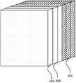
图3是图2所示的超材料面板20的结构示意图,超材料面板20包括多个核心层210以及分布在靠近馈源一侧的多个渐变层220,每一核心层210均由多个超材料单元组成,所述超材料单元包括单元基材211、片状的第一填充层213以及设置在所述单元基材211和第一填充层213之间的多个人造微结构212,如图4以及如图5所示。所述第一填充层213内填充的材料可以是空气、人造微结构以及与所述单元基材相同材料的介质,比如,当需要所述超材料单元内的等效折射率变大时,可以在第一填充层213内填充金属微结构或者是填充具有较大折射率的介质;当需要所述超材料单元内的等效折射率变小时,可以在第一填充层213内填充空气介质或者是不填充任何介质。超材料面板20内的多个超材料核心层210堆叠在一起,且各个核心层210之间等间距排列地组装,或两两片层之间直接前、后表面相粘合地连接成一体。具体实施时,超材料核心层的数目以及各个核心层之间的距离可依据需求来进行设计。每个超材料核心层210由多个超材料单元阵列形成,整个超材料核心层210可看作是由多个超材料单元沿X、Y、Z三个方向阵列排布而成。Fig. 3 is a structural schematic diagram of the metamaterial panel 20 shown in Fig. 2, the metamaterial panel 20 includes a plurality of
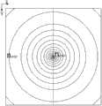
所述超材料面板20的多个核心层210通过改变其内部的折射率分布以实现通过所述超材料面板20后的电磁波等相位辐射,即实现从所述馈源10辐射出的球面电磁波转换为平面电磁波。本发明中每个超材料核心层210的折射率分布均相同,这里仅对一个超材料核心层210的折射率分布规律进行详细描述。通过对人造微结构212的拓扑图案、几何尺寸以及其在单元基材211和第一填充层213上分布的设计,使中间的核心层210的折射率分布满足如下规律:每一层核心层210的折射率分布均相同,每一核心层包括一个以核心层210的中心为圆心的圆形面域,所述圆形面域内圆心处的折射率为最大值nmax且随着半径的增大逐渐减小,相同半径处的折射率相同,如图9所示,给出nmax~nmin的折射率变化图,但应知本发明的折射率变化并不以此为限。本发明设计目的为:使电磁波经过各超材料核心层210时,电磁波偏折角度被逐渐改变并最终平行辐射。通过公式Sinθ=q·Δn,其中θ为所需偏折电磁波的角度、Δn为前后折射率变化差值,q为超材料功能层的厚度并通过计算机仿真即可确定所需参数值并达到本发明设计目的。The plurality of
图8为图9所示超材料核心层折射率分布图的O-O′视图。作为公知常识我们可知,电磁波的折射率与
为使超材料面板20的每一核心层210实现图8以及图9所示折射率的变化,经过理论和实际证明,可对所述人造微结构212的拓扑结构、几何尺寸以及其在单元基材211和第一填充层213上分布的设计,单元基材211采用介电绝缘材料制成,可以为陶瓷材料、高分子材料、铁电材料、铁氧材料、铁磁材料等,高分子材料例如可以是、环氧树脂或聚四氟乙烯。人造微结构212为以一定的几何形状附着在单元基材211上能够对电磁波有响应的金属线,金属线可以是剖面为圆柱状或者扁平状的铜线、银线等,一般采用铜,因为铜丝相对比较便宜,当然金属线的剖面也可以为其他形状,金属线通过蚀刻、电镀、钻刻、光刻、电子刻或离子刻等工艺附着在单元基材211上,所述第一填充层213可以填充不同材料的介质,可以与单元基材211相同的材料,也可以是人造微结构,还可以是空气,所述每一核心层210由多个超材料单元组成,每超材料单元都具有一个人造微结构,每一个超材料单元都会对通过其中的电磁波产生响应,从而影响电磁波在其中的传输,每个超材料单元的尺寸取决于需要响应的电磁波,通常为所需响应的电磁波波长的十分之一,否则空间中包含人造微结构212的超材料单元所组成的排列在空间中不能被视为连续。In order to make each
在单元基材211的选定的情况下,通过调整人造微结构212的形状、尺寸及其在单元基材211上的空间分布和在第一填充层213填充不同折射率的介质,可以调整超材料上各处的等效介电常数及等效磁导率进而改变超材料各处的等效折射率。当人造微结构212采用相同的几何形状时,某处人造微结构的尺寸越大,则该处的等效介电常数越大,折射率也越大。In the selected case of the
本实施例采用的人造微结构212的图案为工字形的衍生图案,由图7可知,雪花状人造微结构212的尺寸从中心向周围逐渐变小,在每一核心层210中心处,雪花状的人造微结构212的尺寸最大,并且在距离中心相同半径处的雪花状人造微结构212的尺寸相同,因此每一核心层210的等效介电常数由中间向四周逐渐变小,中间的等效介电常数最大,因而每一核心层210的折射率从中间向四周逐渐变小,中间部分的折射率最大。The pattern of the
上面结合附图对本发明的实施例进行了描述,但是本发明并不局限于上述的具体实施方式,人造微结构212的图案可以是二维、也可以是三维结构,不限于该实施例中使用的“工”字形,可以为“工”字形的衍生结构,可以是在三维空间中各条边相互垂直的雪花状及雪花状的衍生结构,也可以是其他的几何形状,其中不同的人造微结构212可以是图案相同,但是其设计尺寸不同;也可以是图案和设计尺寸均不相同,只要满足由天线单元发出的电磁波经过超材料面板20传播后可以平行射出即可。The embodiments of the present invention have been described above in conjunction with the accompanying drawings, but the present invention is not limited to the above-mentioned specific embodiments. The pattern of the
本发明实施例中,所述超材料面板20的每一核心层210的折射率以其中心为圆心,随着半径r的变化规律如以下表达式:In the embodiment of the present invention, the refractive index of each
式中nmax表示所述每一核心层210中的最大折射率值,d表示所有核心层210的总厚度,ss表示所述馈源10到最靠近馈源位置的核心层210的距离,n(r)表示所述每一核心层210内半径r处折射率值。In the formula,nmax represents the maximum refractive index value in each
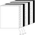
通常当电磁波从一种介质传输到另一种介质的时候,由于阻抗不匹配的问题,会出现一部分电磁波反射,这样影响电磁波的传输性能,本发明中,当从馈源10辐射出来的电磁波入射到超材料面板20时同样会产生反射,为了减少反射对雷达天线的影响,我们在超材料面板20的核心层210一侧设置多个超材料渐变层220,如图3所示。Usually when the electromagnetic wave is transmitted from one medium to another medium, due to the problem of impedance mismatch, a part of the electromagnetic wave will be reflected, which affects the transmission performance of the electromagnetic wave. In the present invention, when the electromagnetic wave radiated from the feed source 10 is incident Reflection will also occur when reaching the metamaterial panel 20. In order to reduce the impact of reflection on the radar antenna, we set multiple metamaterial gradient layers 220 on the
如图5所示,每一超材料渐变层220均包括片状的基板层221、片状的第二填充层223以及设置在所述基板层221和第二填充层223之间的空气层222。所述基板层221可选用高分子聚合物、陶瓷材料、铁电材料、铁氧材料等。其中高分子聚合物优选FR-4或F4B材料。多个超材料渐变层220之间的折射率是不同的,为了匹配空气与核心层210的阻抗,通常是通过调整所述空气层222的宽度和通过在第二填充层223内填充含有不同折射率的介质来实现阻抗匹配,该介质也可以是与基板层221相同的材料,也可以是空气,其中靠近空气的超材料渐变层220的折射率最接近空气且朝核心层210方向折射率逐渐增加。As shown in FIG. 5 , each metamaterial graded
本发明中实施例中,所述超材料面板20的每一渐变层内220的折射率均匀分布的,且多个渐变层220间折射率分布的变化规律如以下表达式:In the embodiment of the present invention, the refractive index of each graded
其中ni表示第i层渐变层220的折射率值,m表示渐变层220的层数,nmin表示所述每一核心层210内的最小折射率值,nmax表示所述每一核心层210中的最大折射率值,其中第m层渐变层220与核心层210靠近,随着m值的变小逐渐远离核心层210,第1层渐变层为最外层渐变层。Wherein ni represents the refractive index value of the i-
综上所述,本发明的一种前馈式雷达天线通过改变超材料面板20内部的折射率分布情况,使得天线远场功率大大地增强了,进而提升了天线传播的距离,同时增加了天线的前后比,使得天线更具方向性。In summary, a feed-forward radar antenna of the present invention greatly increases the far-field power of the antenna by changing the refractive index distribution inside the metamaterial panel 20, thereby increasing the propagation distance of the antenna and increasing the antenna The front-to-back ratio makes the antenna more directional.
上述实施例为本发明较佳的实施方式,但本发明的实施方式并不受上述实施例的限制,其他的任何未违背本发明的精神实质与原理下所作的改变、修饰、替代、组合、简化,均应为等效的置换方式,都包含在本发明的保护范围之内。The above-mentioned embodiment is a preferred embodiment of the present invention, but the embodiment of the present invention is not limited by the above-mentioned embodiment, and any other changes, modifications, substitutions, combinations, Simplifications should be equivalent replacement methods, and all are included in the protection scope of the present invention.
Claims (10)
Priority Applications (2)
| Application Number | Priority Date | Filing Date | Title |
|---|---|---|---|
| CN 201110210338CN102480025B (en) | 2011-07-26 | 2011-07-26 | Feed-forward type radar antenna |
| PCT/CN2011/082925WO2013013469A1 (en) | 2011-07-26 | 2011-11-25 | Front feed radar antenna |
Applications Claiming Priority (1)
| Application Number | Priority Date | Filing Date | Title |
|---|---|---|---|
| CN 201110210338CN102480025B (en) | 2011-07-26 | 2011-07-26 | Feed-forward type radar antenna |
Publications (2)
| Publication Number | Publication Date |
|---|---|
| CN102480025Atrue CN102480025A (en) | 2012-05-30 |
| CN102480025B CN102480025B (en) | 2013-03-13 |
Family
ID=46092562
Family Applications (1)
| Application Number | Title | Priority Date | Filing Date |
|---|---|---|---|
| CN 201110210338ActiveCN102480025B (en) | 2011-07-26 | 2011-07-26 | Feed-forward type radar antenna |
Country Status (1)
| Country | Link |
|---|---|
| CN (1) | CN102480025B (en) |
Cited By (5)
| Publication number | Priority date | Publication date | Assignee | Title |
|---|---|---|---|---|
| CN102769198A (en)* | 2012-06-29 | 2012-11-07 | 深圳光启创新技术有限公司 | Artificial electromagnetic material, radome and antenna system |
| CN102820546A (en)* | 2012-07-31 | 2012-12-12 | 深圳光启创新技术有限公司 | Microwave antenna adopting metal ellipsoid and similar hyperbolic type metamaterial subreflector |
| CN104145373A (en)* | 2012-12-05 | 2014-11-12 | 华为技术有限公司 | Array antenna, configuration method and communication system |
| CN104600438A (en)* | 2015-01-28 | 2015-05-06 | 清华大学 | Multi-beam antenna array based on sliding hole surface |
| CN110824918A (en)* | 2019-10-31 | 2020-02-21 | 大连理工大学 | An adaptive control method for antenna reflector shape and surface |
Citations (4)
| Publication number | Priority date | Publication date | Assignee | Title |
|---|---|---|---|---|
| US20090201572A1 (en)* | 2008-02-07 | 2009-08-13 | Toyota Motor Engineering & Manufacturing North America, Inc. | Metamaterial gradient index lens |
| CN101587990A (en)* | 2009-07-01 | 2009-11-25 | 东南大学 | Broad band cylindrical lens antenna based on artificial electromagnetic materials |
| CN101699659A (en)* | 2009-11-04 | 2010-04-28 | 东南大学 | Lens antenna |
| CN101867094A (en)* | 2010-05-02 | 2010-10-20 | 兰州大学 | A Focused Panel Antenna |
- 2011
- 2011-07-26CNCN 201110210338patent/CN102480025B/enactiveActive
Patent Citations (4)
| Publication number | Priority date | Publication date | Assignee | Title |
|---|---|---|---|---|
| US20090201572A1 (en)* | 2008-02-07 | 2009-08-13 | Toyota Motor Engineering & Manufacturing North America, Inc. | Metamaterial gradient index lens |
| CN101587990A (en)* | 2009-07-01 | 2009-11-25 | 东南大学 | Broad band cylindrical lens antenna based on artificial electromagnetic materials |
| CN101699659A (en)* | 2009-11-04 | 2010-04-28 | 东南大学 | Lens antenna |
| CN101867094A (en)* | 2010-05-02 | 2010-10-20 | 兰州大学 | A Focused Panel Antenna |
Cited By (9)
| Publication number | Priority date | Publication date | Assignee | Title |
|---|---|---|---|---|
| CN102769198A (en)* | 2012-06-29 | 2012-11-07 | 深圳光启创新技术有限公司 | Artificial electromagnetic material, radome and antenna system |
| CN102769198B (en)* | 2012-06-29 | 2014-08-13 | 深圳光启创新技术有限公司 | Artificial electromagnetic material, radome and antenna system |
| CN102820546A (en)* | 2012-07-31 | 2012-12-12 | 深圳光启创新技术有限公司 | Microwave antenna adopting metal ellipsoid and similar hyperbolic type metamaterial subreflector |
| CN102820546B (en)* | 2012-07-31 | 2015-02-04 | 深圳光启创新技术有限公司 | Microwave antenna adopting metal ellipsoid and similar hyperbolic type metamaterial subreflector |
| CN104145373A (en)* | 2012-12-05 | 2014-11-12 | 华为技术有限公司 | Array antenna, configuration method and communication system |
| US9647333B2 (en) | 2012-12-05 | 2017-05-09 | Huawei Technologies Co., Ltd. | Array antenna, configuration method, and communication system |
| CN104600438A (en)* | 2015-01-28 | 2015-05-06 | 清华大学 | Multi-beam antenna array based on sliding hole surface |
| CN104600438B (en)* | 2015-01-28 | 2017-04-19 | 清华大学 | Multi-beam antenna array based on sliding hole surface |
| CN110824918A (en)* | 2019-10-31 | 2020-02-21 | 大连理工大学 | An adaptive control method for antenna reflector shape and surface |
Also Published As
| Publication number | Publication date |
|---|---|
| CN102480025B (en) | 2013-03-13 |
Similar Documents
| Publication | Publication Date | Title |
|---|---|---|
| CN102480024B (en) | Feed-backward type radar antenna | |
| WO2013013465A1 (en) | Cassegrain radar antenna | |
| CN102480031B (en) | Feedback type radar antenna | |
| CN102904044B (en) | Feedback radar antenna | |
| CN102480025A (en) | Feed-forward type radar antenna | |
| CN102480019A (en) | Metamaterial antenna | |
| CN103036038B (en) | A kind of Feed-backward type radar antenna | |
| CN102480032B (en) | Offset feed type radar antenna | |
| CN102891373B (en) | Base station antenna made of metamaterial | |
| CN102480023B (en) | Offset-feed type microwave antenna | |
| CN102480029B (en) | Offset-feed type radar antenna | |
| CN102904045B (en) | Feedforward radar antenna | |
| CN102810755B (en) | Metamaterial antenna | |
| CN102480026B (en) | Feed-forward type radar antenna | |
| CN102790278B (en) | Directional antenna | |
| CN102480060A (en) | High-transmission antenna | |
| CN102904038B (en) | Feedforward radar antenna | |
| CN102904040B (en) | Offset radar antenna | |
| CN102683896B (en) | Radar antenna | |
| CN102800984B (en) | Metamaterial antenna | |
| CN102904036B (en) | A kind of offset-feed type microwave antenna | |
| CN102800982B (en) | Metamaterial antenna | |
| CN103036039B (en) | A kind of offset-feed type radar antenna | |
| WO2013013466A1 (en) | Cassegrain radar antenna | |
| WO2013013468A1 (en) | Offset feed radar antenna |
Legal Events
| Date | Code | Title | Description |
|---|---|---|---|
| C06 | Publication | ||
| PB01 | Publication | ||
| C10 | Entry into substantive examination | ||
| SE01 | Entry into force of request for substantive examination | ||
| C14 | Grant of patent or utility model | ||
| GR01 | Patent grant |