CN102479496B - Local dimming method and liquid crystal display - Google Patents
Local dimming method and liquid crystal displayDownload PDFInfo
- Publication number
- CN102479496B CN102479496BCN201110401179.8ACN201110401179ACN102479496BCN 102479496 BCN102479496 BCN 102479496BCN 201110401179 ACN201110401179 ACN 201110401179ACN 102479496 BCN102479496 BCN 102479496B
- Authority
- CN
- China
- Prior art keywords
- spatial filter
- image
- input image
- block
- backlight
- Prior art date
- Legal status (The legal status is an assumption and is not a legal conclusion. Google has not performed a legal analysis and makes no representation as to the accuracy of the status listed.)
- Expired - Fee Related
Links
Images


Classifications
- G—PHYSICS
- G09—EDUCATION; CRYPTOGRAPHY; DISPLAY; ADVERTISING; SEALS
- G09G—ARRANGEMENTS OR CIRCUITS FOR CONTROL OF INDICATING DEVICES USING STATIC MEANS TO PRESENT VARIABLE INFORMATION
- G09G3/00—Control arrangements or circuits, of interest only in connection with visual indicators other than cathode-ray tubes
- G09G3/20—Control arrangements or circuits, of interest only in connection with visual indicators other than cathode-ray tubes for presentation of an assembly of a number of characters, e.g. a page, by composing the assembly by combination of individual elements arranged in a matrix no fixed position being assigned to or needed to be assigned to the individual characters or partial characters
- G09G3/34—Control arrangements or circuits, of interest only in connection with visual indicators other than cathode-ray tubes for presentation of an assembly of a number of characters, e.g. a page, by composing the assembly by combination of individual elements arranged in a matrix no fixed position being assigned to or needed to be assigned to the individual characters or partial characters by control of light from an independent source
- G09G3/3406—Control of illumination source
- G09G3/342—Control of illumination source using several illumination sources separately controlled corresponding to different display panel areas, e.g. along one dimension such as lines
- G09G3/3426—Control of illumination source using several illumination sources separately controlled corresponding to different display panel areas, e.g. along one dimension such as lines the different display panel areas being distributed in two dimensions, e.g. matrix
- G—PHYSICS
- G09—EDUCATION; CRYPTOGRAPHY; DISPLAY; ADVERTISING; SEALS
- G09G—ARRANGEMENTS OR CIRCUITS FOR CONTROL OF INDICATING DEVICES USING STATIC MEANS TO PRESENT VARIABLE INFORMATION
- G09G2320/00—Control of display operating conditions
- G09G2320/06—Adjustment of display parameters
- G09G2320/0626—Adjustment of display parameters for control of overall brightness
- G09G2320/0646—Modulation of illumination source brightness and image signal correlated to each other
Landscapes
- Engineering & Computer Science (AREA)
- Physics & Mathematics (AREA)
- Computer Hardware Design (AREA)
- General Physics & Mathematics (AREA)
- Theoretical Computer Science (AREA)
- Liquid Crystal Display Device Control (AREA)
- Control Of Indicators Other Than Cathode Ray Tubes (AREA)
- Liquid Crystal (AREA)
Abstract
Description
Translated fromChinese相关申请的交叉引用Cross References to Related Applications
本申请要求于2010年11月25日提交的韩国专利申请第10-2010-0118265号的权益,在此为了所有目的援引该专利申请的全部内容作为参考,就像该专利申请在此被全部公开一样。This application claims the benefit of Korean Patent Application No. 10-2010-0118265 filed on November 25, 2010, which is hereby incorporated by reference in its entirety for all purposes, as if fully disclosed herein Same.
技术领域technical field
本发明涉及局部调光方法以及使用该局部调光方法的液晶显示器。The invention relates to a local dimming method and a liquid crystal display using the local dimming method.
背景技术Background technique
由于液晶显示器的重量轻、体积小和低功耗等的特性,液晶显示器的应用范围逐渐扩大。背光式液晶显示器通过控制施加给液晶层的电场调节从背光单元接收的光来显示图像。Due to the characteristics of the liquid crystal display such as light weight, small size and low power consumption, the application range of the liquid crystal display is gradually expanding. A backlight type liquid crystal display displays images by adjusting light received from a backlight unit by controlling an electric field applied to a liquid crystal layer.
液晶显示器的图像质量依赖于对比度。仅通过调节液晶显示器的液晶层的光透过率来提高对比度是受到限制的。为了解决这一问题,已开发了根据图像调整背光的亮度以显著提高液晶显示器的对比度的背光调光方法。这种背光调光方法通过根据输入图像自动调整背光单元的亮度能够降低功耗。这种背光调光方法包括调整整个显示屏的亮度的全局调光方法和把显示屏分成多个区块并独立调整这些区块的亮度的局部调光方法。The image quality of LCD monitors depends on the contrast ratio. There is a limit to improving the contrast ratio only by adjusting the light transmittance of the liquid crystal layer of the liquid crystal display. To solve this problem, a backlight dimming method that adjusts the brightness of the backlight according to the image to significantly improve the contrast of the liquid crystal display has been developed. This backlight dimming method can reduce power consumption by automatically adjusting the brightness of a backlight unit according to an input image. Such backlight dimming methods include a global dimming method that adjusts the brightness of the entire display screen and a local dimming method that divides the display screen into a plurality of blocks and independently adjusts the brightness of the blocks.
全局调光方法能够提高在前帧与下一帧之间测得的动态对比度。局部调光方法能够在一个帧周期中局部调整显示屏的亮度以提高难于用全域调光方法提高的静态对比度。The global dimming method can improve the dynamic contrast ratio measured between the previous frame and the next frame. The local dimming method can locally adjust the brightness of the display screen in a frame period to improve the static contrast that is difficult to improve with the global dimming method.
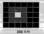
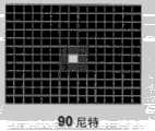
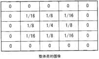
局部调光方法把背光的发光表面划分成多个区块,并且提高对应于亮的图像的区块的背光亮度,同时降低对应于相对暗的图像的区块的背光亮度。如图1A、1B和1C所示,如果增加背光的发光表面的划分的区块的个数,则局部调光方法能够更准确地控制背光亮度。另一方面,如果增加划分的区块的个数,则如图1A、1B和1C所示,一个区块的亮度贡献度则降低。The local dimming method divides the light-emitting surface of the backlight into a plurality of blocks, and increases the backlight brightness of a block corresponding to a bright image, while decreasing the backlight brightness of a block corresponding to a relatively dark image. As shown in FIGS. 1A, 1B and 1C, if the number of divided blocks of the light-emitting surface of the backlight is increased, the local dimming method can control the brightness of the backlight more accurately. On the other hand, if the number of divided blocks is increased, as shown in FIGS. 1A , 1B and 1C, the luminance contribution of a block decreases.
局部调光中的每个区块的调光值可由空间滤波器确定。空间滤波器通过把背光的峰值亮度扩散到周围的区块以减小背光亮度的空间频率,就能够改善不希望有的光晕效应和亮度不一致。传统空间滤波器具有固定的掩模尺寸和固定的掩模系数。于是,如果增加背光发光表面的划分的区块的个数,则使用传统空间滤波器的局部调光方法就降低背光的亮度。这使显示的图像变暗。The dimming value for each block in local dimming may be determined by a spatial filter. Spatial filters can improve unwanted halo effects and brightness inconsistencies by spreading the peak brightness of the backlight to surrounding areas to reduce the spatial frequency of the brightness of the backlight. Traditional spatial filters have a fixed mask size and fixed mask coefficients. Therefore, if the number of divided blocks of the light-emitting surface of the backlight is increased, the local dimming method using the conventional spatial filter reduces the brightness of the backlight. This darkens the displayed image.
发明内容Contents of the invention
本发明的一个目的是提供能够改善在局部调光中产生的亮度恶化的局部调光方法以及使用这种方法的液晶显示器。An object of the present invention is to provide a local dimming method capable of improving brightness deterioration generated in local dimming and a liquid crystal display using the method.
在本发明的一个方面中,提供了一种局部调光方法,该局部调光方法包括:把输入图像划分成N×M(N和M是大于1的正整数)个区块;确定所述区块的代表值,所述代表值表示各个所述区块的平均亮度;分析所述输入图像;设定具有n×n(n是大于3并且等于或小于10的正整数)尺寸的空间滤波器掩模,当所述输入图像被确定为暗的图像时,增加所述空间滤波器掩模中大于0的系数的数量,而当所述输入图像被确定为亮的图像时,减少所述空间滤波器掩模中大于0的系数的数量;以及把所述区块的代表值与所述空间滤波器掩模的系数相乘,以确定每个区块的调光值。In one aspect of the present invention, a local dimming method is provided. The local dimming method includes: dividing an input image into N×M (N and M are positive integers greater than 1) blocks; determining the A representative value of a block, the representative value representing the average brightness of each of the blocks; analyzing the input image; setting a spatial filter having a size of n×n (n is a positive integer greater than 3 and equal to or less than 10) filter mask, when the input image is determined to be a dark image, increase the number of coefficients greater than 0 in the spatial filter mask, and decrease the number of coefficients in the spatial filter mask when the input image is determined to be a bright image the number of coefficients in the spatial filter mask that are greater than 0; and multiplying the representative value of the block by the coefficients of the spatial filter mask to determine a dimming value for each block.
在本发明的另一个方面中,提供了一种液晶显示器,该液晶显示器包括:液晶显示面板;背光单元,所述背光单元包括划分成N×M(N和M是大于1的正整数)个区块的背光发光表面并且把光照射到所述液晶显示面板;背光驱动器,所述背光驱动器控制所述背光单元的用于所述背光发光表面的各个划分的区块的光源;以及局部调光电路,所述局部调光电路基于对输入图像的分析结果,独立控制所述背光发光表面的每个区块的亮度。In another aspect of the present invention, a kind of liquid crystal display is provided, and this liquid crystal display comprises: liquid crystal display panel; a backlight emitting surface of a segment and irradiating light to the liquid crystal display panel; a backlight driver controlling a light source of the backlight unit for each divided segment of the backlight emitting surface; and local dimming The local dimming circuit independently controls the brightness of each section of the backlight emitting surface based on the analysis result of the input image.
附图说明Description of drawings
提供了对本发明的进一步理解并结合在内组成本申请的一部分的附图图示了本发明的实施方式,并与说明书一起用于解释本发明的原理。在附图中:The accompanying drawings, which are included to provide a further understanding of the invention and are incorporated in and constitute a part of this application, illustrate embodiments of the invention and together with the description serve to explain the principle of the invention. In the attached picture:
图1A、1B和1C图示了在通过具有3X3掩模的空间滤波器使一个区块的峰值亮度扩散到3X3区块的情况下,各个区块的亮度;Figures 1A, 1B and 1C illustrate the luminance of individual blocks when the peak luminance of one block is spread to 3x3 blocks by a spatial filter with a 3x3 mask;
图2是本发明实施方式的局部调光电路的框图;2 is a block diagram of a local dimming circuit according to an embodiment of the present invention;
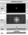
图3A表示在局部调光的情况下,当输入暗的图像时,在液晶显示面板上显示的图像以及发亮的区块;FIG. 3A shows an image displayed on the liquid crystal display panel and bright blocks when a dark image is input in the case of local dimming;
图3B表示在局部调光的情况下,当输入亮的图像时,在液晶显示面板上显示的图像以及发亮的区块;FIG. 3B shows an image displayed on the liquid crystal display panel and illuminated blocks when a bright image is input in the case of local dimming;
图4A是图3A所示的图像的直方图;Figure 4A is a histogram of the image shown in Figure 3A;
图4B是图3B所示的图像的直方图;Figure 4B is a histogram of the image shown in Figure 3B;
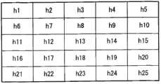
图5A表示空间滤波器的掩模和分配给此掩模的各个区块的系数;Figure 5A shows a mask of a spatial filter and the coefficients assigned to each block of the mask;
图5B表示当输入图3A所示的暗的图像时,空间滤波器的被选择为高数值的掩模系数;Figure 5B shows that when the dark image shown in Figure 3A is input, the mask coefficient of the spatial filter is selected as a high value;
图5C表示当输入图3B所示的亮的图像时,空间滤波器的被选择为低数值的掩模系数;FIG. 5C shows that when the bright image shown in FIG. 3B is input, the mask coefficient of the spatial filter is selected as a low value;
图6图示了空间滤波器的运算;以及Figure 6 illustrates the operation of the spatial filter; and
图7是本发明实施方式的液晶显示器的框图。FIG. 7 is a block diagram of a liquid crystal display according to an embodiment of the present invention.
具体实施方式Detailed ways
现将详细描述本发明的优选的实施方式,本发明的优选的实施方式的示例在附图中示出。Reference will now be made in detail to the preferred embodiments of the present invention, examples of which are illustrated in the accompanying drawings.
参照图2,局部调光电路100包括区块划分单元11、区块代表值确定单元12、图像分析单元14、空间滤波器系数选择器15、空间滤波器13、时间滤波器16、调光值确定单元17以及光源控制器18。2, the
区块划分单元11把输入图像划分成N×M(N和M是大于1的正整数)个区块,所述区块个数大于空间滤波器13的掩模分块的个数。把背光的发光表面划分成对应于所述图像的划分的区块的N×M个区块。The
区块代表值确定单元12确定每个区块的代表值。每个区块的代表值可计算为多达一帧图像的输入图像数据的平均值或平均图像电平(APL)。所述输入图像的平均值对应于在输入图像数据的RGB像素值中的最大值的平均值。APL对应于输入图像数据的亮度值Y的平均值。The block representative
图像分析单元14计算一帧图像的直方图或APL,并且把直方图分析结果或APL提供给空间滤波器系数选择器15。如果输入如图3A所示的具有特定的明亮部分和低亮度背景的图像,则可如图4A所示计算所述图像的直方图。如果输入如图3B所示的整体明亮的图像,则可如图4B所示计算所述图像的直方图。此外,如果输入如图3A所示的具有特定的明亮部分和低亮度背景的图像,所述图像的APL计算为相对低的数值。如果输入如图3B所示的整体明亮的图像,则所述图像的APL计算为高数值。The
图4A的直方图代表了整体暗但具有少量亮像素数据的输入图像,在图4A中的直方图中,高灰度像素的数目少,并且这些高灰度像素都集中在特定的灰度。对于如图3A和4A所示的暗的图像,如果把背光的发光表面的区块看作光源,则与空间滤波器相应而发光的周围光源的数目减少。The histogram in FIG. 4A represents an input image that is overall dark but has a small amount of bright pixel data. In the histogram in FIG. 4A , the number of high grayscale pixels is small, and these high grayscale pixels are all concentrated in a specific grayscale. For dark images as shown in Figs. 3A and 4A, if the regions of the backlit light-emitting surface are considered as light sources, the number of ambient light sources that emit light corresponding to the spatial filter is reduced.
反之,如图3B所示的整体明亮的图像的直方图可如图4B所示来计算。图4B的直方图代表了整体明亮且具有大量亮像素数据的输入图像,在图4B的直方图中,高灰度像素的数目多,并且这些高灰度像素分散在广的灰度范围内。对于如图3B和4B所示的亮的图像,如果把背光的发光表面的区块看作光源,则与空间滤波器相应而发光的周围光源的数量增加。Conversely, the histogram of an overall bright image as shown in FIG. 3B can be calculated as shown in FIG. 4B. The histogram in FIG. 4B represents an input image that is overall bright and has a large amount of bright pixel data. In the histogram in FIG. 4B , the number of high grayscale pixels is large, and these high grayscale pixels are scattered in a wide grayscale range. For bright images as shown in Figures 3B and 4B, if the regions of the backlight's emitting surface are considered as light sources, the number of ambient light sources that emit light corresponding to the spatial filter increases.
空间滤波器系数选择器15选择具有n×n(n是大于3并且等于或小于10的正整数)尺寸的空间滤波器掩模的系数。尽管在以下的描述中空间滤波器的掩模尺寸是5×5,但掩模尺寸并不局限于此。空间滤波器系数选择器15接收来自图像分析单元14的直方图分析结果或APL,并选择空间滤波器的掩模系数,所述掩模系数随所述直方图分析结果或APL而变化。The spatial
空间滤波器系数选择器15把前一帧图像的直方图与当前帧图像的直方图彼此作比较。如果在当前帧图像的直方图中的亮像素的数目减少了,则如图5B所示,空间滤波器系数选择器15增大系数大于0的空间滤波器掩模区块的尺寸,以增加局部调光区块(即背光发光表面区块)的发光光源的数量。反之,如果在当前帧图像的直方图中的亮像素的数目增加了,则如图5C所示,空间滤波器系数选择器15减小系数大于0的空间滤波器掩模区块的尺寸,以减少局部调光区块的发光光源的数量。The spatial
在另一实施方式中,空间滤波器系数选择器15把预定的参照APL与当前帧图像的APL作比较。如果当前帧图像的APL比参照APL低,则如图5B所示,空间滤波器系数选择器15增大系数大于0的空间滤波器掩模区块的尺寸,以增加局部调光区块的发光光源的数量。反之,如果当前帧图像的APL比参照APL高,则如图5C所示,空间滤波器系数选择器15减小系数大于0的空间滤波器掩模区块的尺寸,以减少局部调光区块的发光光源的数量。In another embodiment, the spatial
可将空间滤波器掩模设定为如图5A所示的5×5掩模,并可将系数h1至h25分配给所述掩模的各个区块。当输入如图3A所示的暗的图像时,空间滤波器系数选择器15通过增大系数大于0的掩模区块的尺寸来增加局部调光区块的发光光源的数量。此外,当输入如图3B所示的亮的图像时,空间滤波器系数选择器15通过把分配给所述掩模的边缘的系数用0来代替来减小系数大于0的掩模区块的尺寸,以减少局部调的发光光源的区块的数量。The spatial filter mask can be set as a 5x5 mask as shown in FIG. 5A, and the coefficients h1 to h25 can be assigned to the respective blocks of the mask. When a dark image as shown in FIG. 3A is input, the spatial
空间滤波器系数选择器15把前一帧图像的直方图与当前帧图像的直方图彼此作比较。如果在当前帧图像的直方图中的亮像素的数目减少了,则如图5B所示,增大空间滤波器掩模系数,以提高亮区块的亮度。另一方面,空间滤波器系数选择器15把前一帧图像的直方图与当前帧图像的直方图彼此作比较,如果在当前帧图像的直方图中的亮像素的数目增加了,则如图5C所示,减小空间滤波器掩模系数,以降低亮区块的亮度。The spatial
在另一实施方式中,空间滤波器系数选择器15把预定的参照APL与当前帧图像的APL作比较,如果当前帧图像的APL比参照APL低,则如图5B所示,选择空间滤波器掩模系数为高数值,以提高亮区块的亮度。另一方面,空间滤波器系数选择器15把预定的参照APL与当前帧图像的APL比较,如果当前帧图像的APL比参照APL高,则如图5C所示,选择空间滤波器掩模系数为低数值,以降低亮区块的亮度。In another embodiment, the spatial
如上所述,当输入如图3A所示的暗的图像时,空间滤波器系数选择器15选择空间滤波器掩模系数为高数值,以提高亮区块的亮度,而当输入如图3B所示的亮的图像时,空间滤波器系数选择器15选择空间滤波器掩模系数为相对低的数值,以降低亮区块的亮度。As mentioned above, when a dark image as shown in FIG. 3A is input, the spatial
空间滤波器13把从区块代表值确定单元12输入的各个区块的代表值x 1到x 25与由空间滤波器系数选择器15选择的掩模系数相乘,并且把相乘产生的每个区块的调光值提供给时间滤波器16。空间滤波器13的输出结果g(x13)由方程式(1)表达,并且如图6所示的示意出来。The
g(x13)=x1·h1+x2·h2+…+x24·h24+x25·h25 (1)g(x13)=x1·h1+x2·h2+…+x24·h24+x25·h25 (1)
对于多个帧周期,时间滤波器16分散从空间滤波器13接收的每个区块的调光值,以防止闪烁。时间滤波器16可使用无限脉冲响应滤波器(IIR)或有限脉冲响应滤波器(FIR)在时间上分散每个区块的调光值。例如,时间滤波器16可使用在本申请人于2008年1月23日申请的韩国专利申请第10-2008-0007282号中描述的滤波器,并且时间滤波器16可用任何公知的时间滤波器来实现。For multiple frame periods, the
调光值确定单元17把从时间滤波器16接收的每个区块的调光值编码成串行外围接口(SPI)格式的数据,并且把所述数据提供给光源控制器18的微控制器(MCU)。The dimming
光源控制器18根据脉冲宽度调制(PWM)独立控制背光300的用于各个区块的光源,所述脉冲宽度调制(PWM)利用从调光值确定单元17接收的调光值DIMim改变占空比。PWM信号输入给光源驱动器,以控制光源的打开-关闭比率,即根据输入给光源控制器18的每个区块的调光值确定光源的占空比(%)。PWM信号的占空比随每个区块的调光值增大而增大,而PWM信号的占空比随每个区块的调光值减小而减小。The
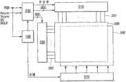
图7是本发明实施方式的液晶显示器的框图。FIG. 7 is a block diagram of a liquid crystal display according to an embodiment of the present invention.
参照图7,液晶显示器包括液晶显示面板200、用于驱动液晶显示面板200的数据线201的源极驱动器210、用于驱动液晶显示面板200的栅极线202的栅极驱动器220、用于控制源极驱动器210和栅极驱动器220的时序控制器230、把光照射到液晶显示面板200的背光单元300、用于驱动背光单元300的光源的光源驱动器310以及用于控制局部调光的局部调光电路100。7, the liquid crystal display includes a liquid
液晶显示面板200包括在两玻璃基板之间的液晶层。在液晶显示面板200中,液晶单元根据与数据线201和栅极线202的交叉结构相应的矩阵形式排列。液晶显示面板200的薄膜晶体管(TFT)阵列基板包括在其上形成的数据线201、栅极线202、TFT、与TFT连接的液晶单元的像素电极以及存储电容。The liquid
液晶显示面板200的滤色器基板包括在其上形成的黑矩阵、滤色器和公共电极。The color filter substrate of the liquid
本发明的液晶显示器可以以垂直电场驱动模式和水平电场驱动模式来实现,垂直电场驱动模式是例如扭曲向列(TN)模式和垂直定向模式,水平电场驱动模式是例如共平面开关模式和边缘场开关模式。The liquid crystal display of the present invention can be realized with vertical electric field driving mode and horizontal electric field driving mode, and vertical electric field driving mode is such as twisted nematic (TN) mode and vertical orientation mode, and horizontal electric field driving mode is such as coplanar switching mode and fringe field switch mode.
液晶显示面板200的像素阵列和与像素阵列相对的背光单元300的发光表面被虚拟划分成用于局部调光的N×N个区块。每个区块包括i×j(i和j是等于或大于2的正整数)个像素和把光照射给这些像素的背光发光表面。每个像素包括三原色或更多色的子像素,并且每个子像素包括液晶单元。The pixel array of the liquid
时序控制器230从外部主系统接收时序信号Vsync、Hsync、DE和DCLK,并且把数字视频数据RGB提供给源极驱动器210。所述时序信号包括垂直同步信号Vsync、水平同步信号Hsync、数据使能信号DE、点时钟信号DCLK等。时序控制器230根据来自主系统的时序信号Vsync、Hsync、DE和DCLK产生用于控制源极驱动器210和栅极驱动器220的操作时序的时序控制信号DDC和GDC。时序控制器230可把从主系统接收的输入图像的数字视频数据RGB提供给局部调光电路100,并且把被局部调光电路100调整的数字视频数据R′G′B′提供给源极驱动器210。The
源极驱动器210在时序控制器230的控制下锁存数字视频数据R′G′B′。此外,源极驱动器210使用正/负伽玛补偿电压把数字视频数据R′G′B′转换为正/负模拟数据电压,并把正/负模拟数据电压提供给数据线201。栅极驱动器220顺序地把与数据线201上的数据电压同步的栅极脉冲(即扫描脉冲)提供给栅极线202。The
背光单元300设置在液晶显示面板200的下方。背光单元300包括由光源驱动器310独立控制的用于各个区块的多个光源,并且把光均匀地照射到液晶显示面板200。背光单元300可以用直下式背光单元或边缘式背光单元来实现。背光单元300的光源可以用如发光二极管(LED)这样的点光源来实现。The
光源驱动器310利用从局部调光电路100接收的、其占空比随每个区块的调光值DIM而改变的PWM信号独立驱动背光单元300的用于各个区块的光源,以控制背光单元300的背光发光表面的每个区块的亮度。The
如图2所示实现的局部调光电路100根据输入图像分析结果选择空间滤波器掩模系数,以及调整各个区块的代表值。局部调光电路100可使用查找表(未示出)补偿低背光亮度,调整从时序控制器230输入的数字视频数据RGB来防止数据灰度饱和,以及把调整过的数据R′G′B′提供给时序控制器230。The
如上所述,当输入暗的图像时,本发明增大空间滤波器掩模的尺寸,而当输入亮的图像时,本发明减小空间滤波器掩模的尺寸,所述暗的图像对应于背光单元的少量的周围光源,所述亮的图像对应于背光单元的大量的周围光源。因此,本发明能够防止在局部调光情况下划分的区块的数量增加时发生的亮度恶化。As mentioned above, the present invention increases the size of the spatial filter mask when a dark image is input, and decreases the size of the spatial filter mask when a bright image is input, which corresponds to The bright image corresponds to a large number of ambient light sources of the backlight unit for a small number of ambient light sources of the backlight unit. Therefore, the present invention can prevent brightness deterioration that occurs when the number of divided blocks increases in the case of local dimming.
尽管已经参照本发明的多个解释性的实施方式描述了本发明,应该理解本领域的技术人员能够在本公开的原理的范围内设计出许多其它的改进和实施方式。更特别地,在本公开、附图和所附权利要求的范围内,在组成部分和/或对象组合设置的安排方面,可以进行各种改变和变型。除对于组成部分和/或安排的改变和变型之外,替代使用对本领域的技术人员来说也将是显而易见的。Although this invention has been described with reference to a number of illustrative embodiments thereof, it should be understood that numerous other modifications and embodiments can be devised by those skilled in the art that will fall within the principles of this disclosure. More particularly, various changes and modifications may be made in the arrangement of the component parts and/or the arrangement of the combined arrangement of the objects within the scope of the disclosure, the drawings and the appended claims. In addition to changes and modifications in the components and/or arrangements, alternative uses will also be apparent to those skilled in the art.
Claims (10)
Translated fromChineseApplications Claiming Priority (2)
| Application Number | Priority Date | Filing Date | Title |
|---|---|---|---|
| KR10-2010-0118265 | 2010-11-25 | ||
| KR1020100118265AKR101324453B1 (en) | 2010-11-25 | 2010-11-25 | Method of local dimming method and liquid crystal display using the same |
Publications (2)
| Publication Number | Publication Date |
|---|---|
| CN102479496A CN102479496A (en) | 2012-05-30 |
| CN102479496Btrue CN102479496B (en) | 2014-01-29 |
Family
ID=46092112
Family Applications (1)
| Application Number | Title | Priority Date | Filing Date |
|---|---|---|---|
| CN201110401179.8AExpired - Fee RelatedCN102479496B (en) | 2010-11-25 | 2011-11-25 | Local dimming method and liquid crystal display |
Country Status (4)
| Country | Link |
|---|---|
| US (1) | US9595229B2 (en) |
| KR (1) | KR101324453B1 (en) |
| CN (1) | CN102479496B (en) |
| TW (1) | TWI447698B (en) |
Cited By (1)
| Publication number | Priority date | Publication date | Assignee | Title |
|---|---|---|---|---|
| WO2020029719A1 (en)* | 2018-08-06 | 2020-02-13 | 深圳创维-Rgb电子有限公司 | Dual layer liquid crystal screen, backlight brightness control method, apparatus, and electronic device |
Families Citing this family (26)
| Publication number | Priority date | Publication date | Assignee | Title |
|---|---|---|---|---|
| US20170272694A1 (en)* | 2004-12-13 | 2017-09-21 | Zeppelin, Inc. | Mobile Phone with Status Memory |
| JP5323272B2 (en)* | 2011-02-09 | 2013-10-23 | 三菱電機株式会社 | LIGHT EMITTING CONTROL DEVICE AND METHOD, LIGHT EMITTING DEVICE, IMAGE DISPLAY DEVICE, PROGRAM, AND RECORDING MEDIUM |
| JP5837009B2 (en)* | 2012-09-26 | 2015-12-24 | キヤノン株式会社 | Display device and control method thereof |
| KR102050451B1 (en)* | 2013-09-23 | 2019-11-29 | 엘지디스플레이 주식회사 | Image display device and method for driving the same |
| CN104050934B (en)* | 2014-05-28 | 2016-03-23 | 京东方科技集团股份有限公司 | Backlight adjustment method, backlight adjustment system and display device |
| US9468065B2 (en)* | 2014-10-15 | 2016-10-11 | Texas Instruments Incorporated | Combined hybrid and local dimming control of light emitting diodes |
| CN106004666B (en)* | 2016-07-18 | 2018-11-13 | 恒大法拉第未来智能汽车(广东)有限公司 | Automobile head-up display system and display methods |
| JP6777485B2 (en)* | 2016-09-26 | 2020-10-28 | エルジー ディスプレイ カンパニー リミテッド | Image display device and image display method |
| CN106328071B (en)* | 2016-10-14 | 2018-09-11 | 京东方科技集团股份有限公司 | A kind of the local backlight light-dimming method and liquid crystal display of liquid crystal display |
| CN107240376A (en)* | 2017-07-07 | 2017-10-10 | 青岛海信电器股份有限公司 | Method for controlling backlight thereof, device and liquid crystal display |
| KR102552922B1 (en)* | 2018-07-09 | 2023-07-10 | 삼성디스플레이 주식회사 | Display apparatus and method of driving the same |
| US10802333B2 (en)* | 2018-08-21 | 2020-10-13 | Himax Technologies Limited | Local dimming system and method adaptable to a backlight of a display |
| US10600370B2 (en)* | 2018-08-22 | 2020-03-24 | Himax Technologies Limited | Local dimming system adaptable to a backlight of a display |
| WO2020112085A1 (en) | 2018-11-27 | 2020-06-04 | Hewlett-Packard Development Company, L.P. | Displays with dimming zones that change |
| CN111785223A (en)* | 2019-04-04 | 2020-10-16 | 海信视像科技股份有限公司 | Double-panel display device |
| CN112086073B (en)* | 2019-06-12 | 2022-02-25 | 奇景光电股份有限公司 | Area dimming system and method for backlighting of displays |
| CN110910840B (en)* | 2019-12-13 | 2021-01-26 | 京东方科技集团股份有限公司 | A liquid crystal display, its backlight adjustment method, and computer readable medium |
| US11562702B2 (en)* | 2020-03-31 | 2023-01-24 | Sharp Kabushiki Kaisha | Dimming unit, and liquid crystal display device |
| JP2021182070A (en)* | 2020-05-19 | 2021-11-25 | ラピスセミコンダクタ株式会社 | Display device and source driver |
| CN111508443B (en) | 2020-05-29 | 2021-08-24 | 京东方科技集团股份有限公司 | Display device and method and device for controlling backlight brightness thereof |
| KR102692173B1 (en)* | 2020-06-16 | 2024-08-06 | 주식회사 엘엑스세미콘 | Dimming value filter apparatus, image data processing apparatus and display device for controlling local dimming |
| CN114627823B (en)* | 2020-12-11 | 2024-06-04 | 纬联电子科技(中山)有限公司 | Liquid crystal display and picture display method |
| CN113554982B (en)* | 2021-07-19 | 2022-09-09 | 京东方科技集团股份有限公司 | Method, system and display panel for pixel brightness compensation of display panel |
| CN116264060A (en)* | 2021-12-15 | 2023-06-16 | 群创光电股份有限公司 | Light source driving circuit and light source driving method |
| CN114420059B (en)* | 2021-12-31 | 2023-12-12 | 海宁奕斯伟集成电路设计有限公司 | Backlight control method and device and display equipment |
| CN114420061B (en)* | 2022-01-27 | 2023-05-23 | 深圳Tcl数字技术有限公司 | Screen brightness adjusting method and device, storage medium and display device |
Citations (1)
| Publication number | Priority date | Publication date | Assignee | Title |
|---|---|---|---|---|
| CN101425275A (en)* | 2007-10-31 | 2009-05-06 | 三星电子株式会社 | Display device and driving method thereof |
Family Cites Families (10)
| Publication number | Priority date | Publication date | Assignee | Title |
|---|---|---|---|---|
| JP2004004532A (en)* | 2002-03-25 | 2004-01-08 | Sharp Corp | Video display device |
| KR101604652B1 (en)* | 2008-06-04 | 2016-03-21 | 삼성디스플레이 주식회사 | Local dimming method of light source, light-source apparatus performing for the method and display apparatus having the light-source apparatus |
| US8917293B2 (en)* | 2008-06-27 | 2014-12-23 | Sharp Kabushiki Kaisha | Control device for liquid crystal display device, liquid crystal display device, method for controlling liquid crystal display device, program, and storage medium |
| KR100950682B1 (en)* | 2008-07-24 | 2010-03-31 | 전자부품연구원 | Display device and method |
| KR20100048391A (en)* | 2008-10-31 | 2010-05-11 | 엘지전자 주식회사 | An image display device |
| KR101537418B1 (en)* | 2009-04-01 | 2015-07-17 | 엘지디스플레이 주식회사 | Liquid crystal display and driving method thereof |
| KR101294851B1 (en)* | 2009-04-01 | 2013-08-08 | 엘지디스플레이 주식회사 | Liquid crystal display and driving method of thereof |
| EP2284827A1 (en)* | 2009-07-15 | 2011-02-16 | Trident Microsystems (Far East) Ltd. | Backlight unit and control method for the same |
| BR112012008070A2 (en)* | 2009-07-29 | 2016-03-01 | Sharp Kk | image display device and image display method |
| JP5661336B2 (en)* | 2010-05-28 | 2015-01-28 | 日立マクセル株式会社 | Liquid crystal display |
- 2010
- 2010-11-25KRKR1020100118265Apatent/KR101324453B1/ennot_activeExpired - Fee Related
- 2011
- 2011-11-23USUS13/304,011patent/US9595229B2/enactiveActive
- 2011-11-25CNCN201110401179.8Apatent/CN102479496B/ennot_activeExpired - Fee Related
- 2011-11-25TWTW100143449Apatent/TWI447698B/ennot_activeIP Right Cessation
Patent Citations (1)
| Publication number | Priority date | Publication date | Assignee | Title |
|---|---|---|---|---|
| CN101425275A (en)* | 2007-10-31 | 2009-05-06 | 三星电子株式会社 | Display device and driving method thereof |
Cited By (1)
| Publication number | Priority date | Publication date | Assignee | Title |
|---|---|---|---|---|
| WO2020029719A1 (en)* | 2018-08-06 | 2020-02-13 | 深圳创维-Rgb电子有限公司 | Dual layer liquid crystal screen, backlight brightness control method, apparatus, and electronic device |
Also Published As
| Publication number | Publication date |
|---|---|
| US9595229B2 (en) | 2017-03-14 |
| TWI447698B (en) | 2014-08-01 |
| CN102479496A (en) | 2012-05-30 |
| US20120133685A1 (en) | 2012-05-31 |
| TW201222516A (en) | 2012-06-01 |
| KR101324453B1 (en) | 2013-10-31 |
| KR20120056634A (en) | 2012-06-04 |
Similar Documents
| Publication | Publication Date | Title |
|---|---|---|
| CN102479496B (en) | Local dimming method and liquid crystal display | |
| US10665181B2 (en) | Backlights with dynamic dimming ranges | |
| JP5122927B2 (en) | Image display device and image display method | |
| KR100928755B1 (en) | Image display device and image display method with adjustable brightness | |
| CN102314844B (en) | Liquid crystal display device and method for local dimming driving of the same | |
| CN101286300B (en) | Display device and method for adjusting its brightness | |
| JP4796038B2 (en) | Image display method | |
| US8111238B2 (en) | Liquid crystal display and dimming controlling method thereof | |
| CN102074208B (en) | Liquid crystal display and local dimming control method thereof | |
| CN105448245B (en) | Backlight illumination compensation method and display device | |
| TWI426492B (en) | Liquid crystal display and method of local dimming thereof | |
| CN101785044B (en) | Image display device | |
| JP5523278B2 (en) | Liquid crystal display device and driving method thereof | |
| KR102073065B1 (en) | Liquid crystal display and method for driving the same | |
| US8400385B2 (en) | Method for enhancing an image displayed on an LCD device | |
| CN104011786A (en) | video display device | |
| WO2012124646A1 (en) | Video display device | |
| JP2010250320A (en) | Pixel data correction method and display device for performing the same | |
| WO2009086742A1 (en) | Method and apparatus for enhancing an image displayed on an lcd device | |
| KR102438248B1 (en) | Dimming control circuit, liquid crystal display including the dimming control circuit, and dimming control method of the liquid crystal display | |
| JP4987134B1 (en) | Video display device | |
| KR101633114B1 (en) | Liquid crystal display and picture quality controlling method thereof | |
| JP5039218B1 (en) | Video display device | |
| TWI427603B (en) | Display and driving apparatus and method thereof | |
| JP2012194559A (en) | Image display |
Legal Events
| Date | Code | Title | Description |
|---|---|---|---|
| C06 | Publication | ||
| PB01 | Publication | ||
| C10 | Entry into substantive examination | ||
| SE01 | Entry into force of request for substantive examination | ||
| C14 | Grant of patent or utility model | ||
| GR01 | Patent grant | ||
| CF01 | Termination of patent right due to non-payment of annual fee | Granted publication date:20140129 Termination date:20181125 | |
| CF01 | Termination of patent right due to non-payment of annual fee |