CN102478606A - Overcurrent protection resistance detection circuit for voltage-reduction transfer circuit - Google Patents
Overcurrent protection resistance detection circuit for voltage-reduction transfer circuitDownload PDFInfo
- Publication number
- CN102478606A CN102478606ACN2010105610424ACN201010561042ACN102478606ACN 102478606 ACN102478606 ACN 102478606ACN 2010105610424 ACN2010105610424 ACN 2010105610424ACN 201010561042 ACN201010561042 ACN 201010561042ACN 102478606 ACN102478606 ACN 102478606A
- Authority
- CN
- China
- Prior art keywords
- resistance
- circuit
- amplifier
- overcurrent protection
- connects
- Prior art date
- Legal status (The legal status is an assumption and is not a legal conclusion. Google has not performed a legal analysis and makes no representation as to the accuracy of the status listed.)
- Pending
Links
Images

Classifications
- H—ELECTRICITY
- H02—GENERATION; CONVERSION OR DISTRIBUTION OF ELECTRIC POWER
- H02M—APPARATUS FOR CONVERSION BETWEEN AC AND AC, BETWEEN AC AND DC, OR BETWEEN DC AND DC, AND FOR USE WITH MAINS OR SIMILAR POWER SUPPLY SYSTEMS; CONVERSION OF DC OR AC INPUT POWER INTO SURGE OUTPUT POWER; CONTROL OR REGULATION THEREOF
- H02M1/00—Details of apparatus for conversion
- H02M1/32—Means for protecting converters other than automatic disconnection
- H—ELECTRICITY
- H02—GENERATION; CONVERSION OR DISTRIBUTION OF ELECTRIC POWER
- H02M—APPARATUS FOR CONVERSION BETWEEN AC AND AC, BETWEEN AC AND DC, OR BETWEEN DC AND DC, AND FOR USE WITH MAINS OR SIMILAR POWER SUPPLY SYSTEMS; CONVERSION OF DC OR AC INPUT POWER INTO SURGE OUTPUT POWER; CONTROL OR REGULATION THEREOF
- H02M3/00—Conversion of DC power input into DC power output
- H02M3/02—Conversion of DC power input into DC power output without intermediate conversion into AC
- H02M3/04—Conversion of DC power input into DC power output without intermediate conversion into AC by static converters
- H02M3/10—Conversion of DC power input into DC power output without intermediate conversion into AC by static converters using discharge tubes with control electrode or semiconductor devices with control electrode
- H02M3/145—Conversion of DC power input into DC power output without intermediate conversion into AC by static converters using discharge tubes with control electrode or semiconductor devices with control electrode using devices of a triode or transistor type requiring continuous application of a control signal
- H02M3/155—Conversion of DC power input into DC power output without intermediate conversion into AC by static converters using discharge tubes with control electrode or semiconductor devices with control electrode using devices of a triode or transistor type requiring continuous application of a control signal using semiconductor devices only
- H02M3/156—Conversion of DC power input into DC power output without intermediate conversion into AC by static converters using discharge tubes with control electrode or semiconductor devices with control electrode using devices of a triode or transistor type requiring continuous application of a control signal using semiconductor devices only with automatic control of output voltage or current, e.g. switching regulators
- H02M3/158—Conversion of DC power input into DC power output without intermediate conversion into AC by static converters using discharge tubes with control electrode or semiconductor devices with control electrode using devices of a triode or transistor type requiring continuous application of a control signal using semiconductor devices only with automatic control of output voltage or current, e.g. switching regulators including plural semiconductor devices as final control devices for a single load
- H02M3/1588—Conversion of DC power input into DC power output without intermediate conversion into AC by static converters using discharge tubes with control electrode or semiconductor devices with control electrode using devices of a triode or transistor type requiring continuous application of a control signal using semiconductor devices only with automatic control of output voltage or current, e.g. switching regulators including plural semiconductor devices as final control devices for a single load comprising at least one synchronous rectifier element
- G—PHYSICS
- G01—MEASURING; TESTING
- G01R—MEASURING ELECTRIC VARIABLES; MEASURING MAGNETIC VARIABLES
- G01R31/00—Arrangements for testing electric properties; Arrangements for locating electric faults; Arrangements for electrical testing characterised by what is being tested not provided for elsewhere
- G01R31/40—Testing power supplies
- H—ELECTRICITY
- H02—GENERATION; CONVERSION OR DISTRIBUTION OF ELECTRIC POWER
- H02M—APPARATUS FOR CONVERSION BETWEEN AC AND AC, BETWEEN AC AND DC, OR BETWEEN DC AND DC, AND FOR USE WITH MAINS OR SIMILAR POWER SUPPLY SYSTEMS; CONVERSION OF DC OR AC INPUT POWER INTO SURGE OUTPUT POWER; CONTROL OR REGULATION THEREOF
- H02M1/00—Details of apparatus for conversion
- H02M1/0003—Details of control, feedback or regulation circuits
- H02M1/0009—Devices or circuits for detecting current in a converter
- Y—GENERAL TAGGING OF NEW TECHNOLOGICAL DEVELOPMENTS; GENERAL TAGGING OF CROSS-SECTIONAL TECHNOLOGIES SPANNING OVER SEVERAL SECTIONS OF THE IPC; TECHNICAL SUBJECTS COVERED BY FORMER USPC CROSS-REFERENCE ART COLLECTIONS [XRACs] AND DIGESTS
- Y02—TECHNOLOGIES OR APPLICATIONS FOR MITIGATION OR ADAPTATION AGAINST CLIMATE CHANGE
- Y02B—CLIMATE CHANGE MITIGATION TECHNOLOGIES RELATED TO BUILDINGS, e.g. HOUSING, HOUSE APPLIANCES OR RELATED END-USER APPLICATIONS
- Y02B70/00—Technologies for an efficient end-user side electric power management and consumption
- Y02B70/10—Technologies improving the efficiency by using switched-mode power supplies [SMPS], i.e. efficient power electronics conversion e.g. power factor correction or reduction of losses in power supplies or efficient standby modes
Landscapes
- Engineering & Computer Science (AREA)
- Power Engineering (AREA)
- Dc-Dc Converters (AREA)
Abstract
Translated fromChinese
Description
Translated fromChinese技术领域technical field
本发明涉及一种降低式变换电路,特别涉及一种降压式变换电路的过流保护阻值侦测电路。The invention relates to a step-down conversion circuit, in particular to an overcurrent protection resistance detection circuit of a step-down conversion circuit.
背景技术Background technique
现有的降压式变换电路(Buck电路)在进行过流保护设计时,通常都是利用人工依次将不同阻值的电阻分别接入Buck电路进行测试,以此获得过流保护需要的电阻。这种方法需要不断地将电阻焊接至电路的相应位置进行测试,操作不便,而且浪费大量的人力和时间。When the existing step-down conversion circuit (Buck circuit) is designed for over-current protection, resistors with different resistance values are connected to the Buck circuit in turn for testing manually, so as to obtain the resistance required for over-current protection. This method needs to continuously weld the resistance to the corresponding position of the circuit for testing, which is inconvenient to operate and wastes a lot of manpower and time.
发明内容Contents of the invention
鉴于以上内容,有必要提供一种降压式变换电路的过流保护阻值侦测电路,以自动获得降压式变换电路过流保护的最佳电阻值。In view of the above, it is necessary to provide an over-current protection resistance detection circuit of the step-down conversion circuit to automatically obtain the optimal resistance value of the over-current protection of the step-down conversion circuit.
一种降压式变换电路的过流保护阻值侦测电路,应用于降压式变换电路,该降压式变换电路包括PWM控制器及电压输出端,所述过流保护阻值侦测电路包括:An overcurrent protection resistance detection circuit of a step-down conversion circuit, applied to a step-down conversion circuit, the step-down conversion circuit includes a PWM controller and a voltage output terminal, the overcurrent protection resistance detection circuit include:
一电阻设定电路,用于将不同的电阻加载至降压式变换电路的PWM控制器上;A resistance setting circuit, which is used to load different resistances to the PWM controller of the step-down conversion circuit;
一开关电路,用于控制过流保护阻值侦测电路的开启及关闭;A switch circuit, used to control the opening and closing of the overcurrent protection resistance detection circuit;
一电流采集电路,用于将所述降压式变换电路的电压输出端输出的电压转换为电流并经过放大处理后输出给所述电阻设定电路,以使所述电阻设定电路将从所述电流采集电路接收到的电流值与一预设电流值进行比较以获得一电阻值;及A current acquisition circuit, used to convert the voltage output from the voltage output terminal of the step-down conversion circuit into a current and output it to the resistance setting circuit after amplifying, so that the resistance setting circuit comparing the current value received by the current acquisition circuit with a preset current value to obtain a resistance value; and
一显示单元,用于将所述电阻设定电路比较后的电阻值进行显示。A display unit is used for displaying the resistance value compared by the resistance setting circuit.
相较现有技术,所述降压式变换电路的过流保护阻值侦测电路通过将不同阻值的电阻自动加载至降压式变换电路,以方便的获得所述降压式变换电路过流保护设计中需要的电阻值,操作方便,节省人力和时间。Compared with the prior art, the overcurrent protection resistance detection circuit of the step-down conversion circuit automatically loads resistors with different resistance values to the step-down conversion circuit to conveniently obtain the overcurrent protection of the step-down conversion circuit. The resistance value required in the current protection design is easy to operate and saves manpower and time.
附图说明Description of drawings
下面参照附图结合具体实施方式对本发明作进一步的描述。The present invention will be further described below in conjunction with specific embodiments with reference to the accompanying drawings.
图1为现有一种降压式变换电路的电路图。FIG. 1 is a circuit diagram of an existing step-down conversion circuit.
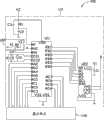
图2及图3为本发明降压式变换电路的过流保护阻值侦测电路的较佳实施方式电路图。2 and 3 are circuit diagrams of a preferred embodiment of the overcurrent protection resistance detection circuit of the buck converter circuit of the present invention.
主要元件符号说明Description of main component symbols
过流保护阻值侦测电路 100Overcurrent protection
降压式变换电路 200Step-down conversion circuit 200
PWM控制器 20PWM controller 20
PWM驱动单元 21PWM drive unit 21
电阻设定电路 110
开关电路 120
电流采集电路 130
场效应管 Q1、Q2FET Q1, Q2
电感 LInductance L
电压输出端 VoutVoltage output terminal Vout
电容 C0-9Capacitor C0-9
电阻 R1-R10Resistor R1-R10
变压器 T1Transformer T1
负载 131
放大器 U1-U3Amplifier U1-U3
数字电位器 U22Digital Potentiometer U22
单片机 U11MCU U11
晶体振荡器 X1Crystal Oscillator X1
开关 K1switch K1
显示单元 140
具体实施方式Detailed ways
请参照图1至图3,本发明降压式变换电路的过流保护阻值侦测电路100用于获得一降压式变换电路(以下简称Buck电路)200过流保护的最佳电阻值,该Buck电路200设置于一电路板(图未示),包括脉宽调制(pulse widthmodulation,PWM)控制器20、PWM驱动单元21、场效应管Q1、Q2、电压输入端Vin及电压输出端Vout。所述PWM控制器20连接至过流保护阻值侦测电路100,所述所述PWM驱动单元21连接所述PWM控制器20及所述场效应管Q1及Q2的栅极,用于接收所述PWM控制器20输出的控制信号以分别为场效应管Q1及Q2提供低通驱动信号及高通驱动信号,以分别控制场效应管Q1及Q2的截止与导通。所述场效应管Q2的漏极连接所述电压输入端Vin,所述场效应管Q1的源极接地,漏极连接至场效应管Q2的源极。该场效应管Q1的漏极还通过串联的电感L及电容C0接地。该电压输出端Vout连接至串联的电感L及电容C0之间,以输出一驱动电压给其它元件并连接至过流保护阻值侦测电路100。Please refer to FIG. 1 to FIG. 3 , the over-current protection
该过流保护阻值侦测电路100包括一电阻设定电路110、一开关电路120、一电流采集电路130及一显示单元140。所述电阻设定电路110用于将不同的电阻加载至buck电路200的PWM控制器20,所述开关电路120用于控制过流保护阻值侦测电路100的开启及关闭,所述电流采集电路130用于将buck电路200的电压输出端Vout输出的电压转换为电流并经过放大处理后通过所述显示单元140进行显示。The overcurrent protection
所述电阻设备电路110包括一单片机U11、一数字电位器U22、电阻R1、电容C1-C5及一晶体振荡器X1。所述数字电位器U22的输入端A0-A3连接所述单片机U11的输出端RB7-RB4,所述数字电位器U22的时钟端SCL连接所述单片机U11的输出端RB3,所述数字电位器U22的数据端SDA连接所述单片机U11的输出端RB2。所述数字电位器U22的电压端VCC连接一电压源V1及经所述电容C1接地。所述数字电位器U22的输出端VH0、VW0连接所述PWM控制器20。所述数字电位器U22的接地端VSS、VL0均接地。所述单片机U11的电压端VDD连接一电压源VC及依次经所述电阻R1及电容C2接地,所述电容C3串接在所述电压源VC与地之间,所述单片机U11的电压端MP连接在所述电阻R1与电容C2之间的节点。所述单片机U11的时钟端OCS1经所述电容C4接地,其时钟端OCS2经所述电容C5接地,所述晶体振荡器X1串接在所述单片机U11的时钟端OCS1与OCS2之间。在本实施方式中,所述单片机U11的型号为PIC16F73。所述数字电位器U22的型号为X9241。所述电压源V1为一5V电源,VC为一任意电源。The
所述开关电路120包括一电阻R2及一开关K1。所述单片机U11的输入端RA1经所述电阻R2连接所述电压源VC及经所述开关K1接地。The
所述电流采集电路130包括一变压器T1、负载131、放大器U1-U3、电阻R3-R12及电容C6-C9。所述负载131经所述变压器T1的初级线圈连接所述电压输出端Vout,所述电阻R3串接在所述变压器T1的次级线圈的两端之间,所述变压器T1的次级线圈的第一端经所述电阻R4连接所述放大器U1的同相输入端,所述电容C6串接在所述放大器U1的同相输入端与地之间,所述电容C7串接在所述放大器U1的同相输入端与反相输入端之间,所述电阻R5串接在所述放大器U1的反相输入端与输出端之间,所述放大器U1的输出端经所述电阻R6连接所述放大器U3的反相输入端,所述电阻R7串接在所述放大器U3的反相输入端与输出端之间,所述电阻R8串接在所述放大器U1的反相输入端与所述放大器U2的反相输入端之间,所述电阻R9串接在所述放大器U2的反相输入端与输出端之间,所述变压器T1的次级线圈的第二端经所述电阻R10连接所述放大器U2的同相输入端,所述电容C9串接在所述放大器U2的同相输入端与地之间,所述电容C8串接在所述放大器U2的反相输入端与同相输入端之间,所述放大器U2的输出端经所述电阻R11连接所述放大器U3的同相输入端,所述电阻R12串接在所述放大器U3的同相输入端与地之间,所述放大器U3的输出端连接所述单片机U11的输入端RA0。所述放大器U1-U3的接地端均接地,其电压端均连接一电压源V2。在本实施方式中,所述电压源V2为一12V电源,所述变压器T1为一电流采样变压器。The
所述显示单元140连接所述单片机U11的I/O端RA2-RA5、RC0-RC7。The
在本实施例中,该单片机U11的输出端RB4-RB7具有16种输出状态,每一种输出状态对应控制所述数字电位器U22将相应阻值的电阻接入buck电路200。例如,当该单片机U11的输出端RB4-RB7输出状态为0000时,其控制该数字电位器U22将阻值为0.5欧姆的电阻接入buck电路200。当该单片机U11的输出端RB4-RB7输出状态为0001时,其控制该数字电位器U22将阻值为1欧姆的电阻接入buck电路200,依此类推。In this embodiment, the output terminals RB4-RB7 of the single-chip microcomputer U11 have 16 output states, and each output state corresponds to controlling the digital potentiometer U22 to connect a resistor with a corresponding resistance value to the buck circuit 200 . For example, when the output state of the output terminals RB4-RB7 of the microcontroller U11 is 0000, it controls the digital potentiometer U22 to connect a resistor with a resistance value of 0.5 ohms to the buck circuit 200 . When the output state of the output terminals RB4-RB7 of the microcontroller U11 is 0001, it controls the digital potentiometer U22 to connect a resistor with a resistance value of 1 ohm to the buck circuit 200, and so on.
下面介绍本发明较佳实施方式的工作原理:The working principle of the preferred embodiment of the present invention is introduced below:
首先,按下开关K1,以启动单片机U11,单片机U11启动后,通过所述输出端RB4-RB7输出状态为0000的控制信号给所述数字电位器U22,以将0.5欧姆的电阻接入buck电路200。此时,所述PWM控制器20输出PWM信号给所述PWM驱动单元21,以使其分别控制第一场效应管Q1及第二场效应管Q2截止与导通,所述电压输出端Vout输出电压给其他元件,并且所述输出电压经所述变压器T1及负载131后转换为一相应的电流值并经所述放大器U1-U3依次放大后通过所述单片机U11的引脚RA0提供给所述单片机U11,所述单片机U11将此时的电流值与一预设电流值进行比较,并将此时的电流值及0.5欧姆的电阻值通过所述显示单元140进行显示。如果所述单片机U11接收到的电流值小于预设电流值,则所述单片机U11的输出端RB4-RB7将输出状态为0001的控制信号给所述数字电位器U22,以控制所述数字电位器U22重新选择一电阻值,如1欧姆的电阻接入buck电路200,其工作原理与上述工作原理相同,在此不再赘述。直到所述单片机U11接收到的电流值大于所述预设电流值,此时所述单片机U11不输出控制信号给所述数字电位器U22,所述PWM控制器20将不输出PWM信号,所述电压输出端Vout没有电压输出。此时,所述单片机U11通过所述显示单元140显示的上次得到的电阻值即就是所述buck电路200过流保护设计中需要的电阻值。First, press the switch K1 to start the single-chip microcomputer U11, after the single-chip microcomputer U11 is started, output a control signal with a state of 0000 through the output terminals RB4-RB7 to the digital potentiometer U22 to connect a 0.5 ohm resistor to the buck circuit 200. At this time, the PWM controller 20 outputs a PWM signal to the PWM driving unit 21, so that it controls the first field effect transistor Q1 and the second field effect transistor Q2 to be turned off and turned on respectively, and the voltage output terminal Vout outputs voltage to other components, and the output voltage is converted into a corresponding current value by the transformer T1 and the
本发明的过流保护阻值侦测电路100通过将不同阻值的电阻自动加载至buck电路200,以获得所述buck电路200过流保护设计中需要的电阻值,操作方便,节省人力和时间。The overcurrent protection
Claims (8)
Priority Applications (2)
| Application Number | Priority Date | Filing Date | Title |
|---|---|---|---|
| CN2010105610424ACN102478606A (en) | 2010-11-26 | 2010-11-26 | Overcurrent protection resistance detection circuit for voltage-reduction transfer circuit |
| US12/962,562US20120133349A1 (en) | 2010-11-26 | 2010-12-07 | Measurement circuit for buck circuit |
Applications Claiming Priority (1)
| Application Number | Priority Date | Filing Date | Title |
|---|---|---|---|
| CN2010105610424ACN102478606A (en) | 2010-11-26 | 2010-11-26 | Overcurrent protection resistance detection circuit for voltage-reduction transfer circuit |
Publications (1)
| Publication Number | Publication Date |
|---|---|
| CN102478606Atrue CN102478606A (en) | 2012-05-30 |
Family
ID=46091316
Family Applications (1)
| Application Number | Title | Priority Date | Filing Date |
|---|---|---|---|
| CN2010105610424APendingCN102478606A (en) | 2010-11-26 | 2010-11-26 | Overcurrent protection resistance detection circuit for voltage-reduction transfer circuit |
Country Status (2)
| Country | Link |
|---|---|
| US (1) | US20120133349A1 (en) |
| CN (1) | CN102478606A (en) |
Cited By (3)
| Publication number | Priority date | Publication date | Assignee | Title |
|---|---|---|---|---|
| CN103268144A (en)* | 2013-06-07 | 2013-08-28 | 张宁 | Power monitoring device and overcurrent protection method |
| CN107132418A (en)* | 2017-06-16 | 2017-09-05 | 珠海伊托科技有限公司 | The resistance detecting circuit of overflow protecting element |
| CN109102767A (en)* | 2018-08-24 | 2018-12-28 | 昆山龙腾光电有限公司 | A kind of impedance detection circuit and liquid crystal display device |
Citations (7)
| Publication number | Priority date | Publication date | Assignee | Title |
|---|---|---|---|---|
| CN1286520A (en)* | 1999-09-01 | 2001-03-07 | 英特赛尔公司 | DC-DC converter of synchronous rectification type with improved current sensing |
| CN1605148A (en)* | 2001-12-14 | 2005-04-06 | 英特赛尔美国股份有限公司 | Programmable Current Sense Circuit Provides Continuous Temperature Compensation to DC-DC Converters |
| US20050258808A1 (en)* | 2004-05-24 | 2005-11-24 | Ming-Hsueh Chen | Controller in a voltage mode buck converter for implementing a mode-switch function and an over-current protection by a multifunction pin and method thereof |
| CN1732612A (en)* | 2002-12-31 | 2006-02-08 | 英特赛尔美国股份有限公司 | Mechanism to provide overvoltage protection during DC-DC transmission power-up |
| CN1736018A (en)* | 2002-11-14 | 2006-02-15 | 菲尔风暴有限公司 | power converter circuit and method |
| CN1848634A (en)* | 2005-03-17 | 2006-10-18 | 国际整流器公司 | POL system architecture with analog bus |
| CN101222178A (en)* | 2007-01-11 | 2008-07-16 | 联想(新加坡)私人有限公司 | DC-DC converter, electronic equipment and method for reducing power consumption |
Family Cites Families (9)
| Publication number | Priority date | Publication date | Assignee | Title |
|---|---|---|---|---|
| US5451879A (en)* | 1992-08-14 | 1995-09-19 | Moore; Clayton K. | Electromechanical relay monitoring system with status clocking |
| US5479090A (en)* | 1993-11-24 | 1995-12-26 | Raytheon Company | Power converter having optimal dynamic operation |
| US5913836A (en)* | 1996-02-20 | 1999-06-22 | Allied Health Association, Inc. | Body toning method and apparatus |
| US6011992A (en)* | 1996-05-09 | 2000-01-04 | Church Of Spirtual Technology | System for measuring and indicating changes in the resistance of a living body |
| US5982596A (en)* | 1998-05-05 | 1999-11-09 | George Authur Spencer | Load center monitor and digitally enhanced circuit breaker system for monitoring electrical power lines |
| WO2000002102A1 (en)* | 1998-07-01 | 2000-01-13 | Sportvision System, Llc | System for measuring a jump |
| US20070200540A1 (en)* | 2004-07-14 | 2007-08-30 | Rohm Co., Ltd. | Power Source Device |
| US7113077B2 (en)* | 2005-01-21 | 2006-09-26 | Autotronic Controls Corporation | System and method for providing a display utilizing a fast photon indicator |
| CA2660245C (en)* | 2006-08-09 | 2015-11-24 | Mbda Uk Limited | Inductive power system |
- 2010
- 2010-11-26CNCN2010105610424Apatent/CN102478606A/enactivePending
- 2010-12-07USUS12/962,562patent/US20120133349A1/ennot_activeAbandoned
Patent Citations (7)
| Publication number | Priority date | Publication date | Assignee | Title |
|---|---|---|---|---|
| CN1286520A (en)* | 1999-09-01 | 2001-03-07 | 英特赛尔公司 | DC-DC converter of synchronous rectification type with improved current sensing |
| CN1605148A (en)* | 2001-12-14 | 2005-04-06 | 英特赛尔美国股份有限公司 | Programmable Current Sense Circuit Provides Continuous Temperature Compensation to DC-DC Converters |
| CN1736018A (en)* | 2002-11-14 | 2006-02-15 | 菲尔风暴有限公司 | power converter circuit and method |
| CN1732612A (en)* | 2002-12-31 | 2006-02-08 | 英特赛尔美国股份有限公司 | Mechanism to provide overvoltage protection during DC-DC transmission power-up |
| US20050258808A1 (en)* | 2004-05-24 | 2005-11-24 | Ming-Hsueh Chen | Controller in a voltage mode buck converter for implementing a mode-switch function and an over-current protection by a multifunction pin and method thereof |
| CN1848634A (en)* | 2005-03-17 | 2006-10-18 | 国际整流器公司 | POL system architecture with analog bus |
| CN101222178A (en)* | 2007-01-11 | 2008-07-16 | 联想(新加坡)私人有限公司 | DC-DC converter, electronic equipment and method for reducing power consumption |
Cited By (6)
| Publication number | Priority date | Publication date | Assignee | Title |
|---|---|---|---|---|
| CN103268144A (en)* | 2013-06-07 | 2013-08-28 | 张宁 | Power monitoring device and overcurrent protection method |
| CN103268144B (en)* | 2013-06-07 | 2016-09-07 | 张宁 | Apparatus for monitoring power supply and over-current protection method |
| CN107132418A (en)* | 2017-06-16 | 2017-09-05 | 珠海伊托科技有限公司 | The resistance detecting circuit of overflow protecting element |
| CN107132418B (en)* | 2017-06-16 | 2024-04-09 | 珠海伊托科技有限公司 | Resistance detection system of overcurrent protection element |
| CN109102767A (en)* | 2018-08-24 | 2018-12-28 | 昆山龙腾光电有限公司 | A kind of impedance detection circuit and liquid crystal display device |
| CN109102767B (en)* | 2018-08-24 | 2021-05-28 | 昆山龙腾光电股份有限公司 | Impedance detection circuit and liquid crystal display device |
Also Published As
| Publication number | Publication date |
|---|---|
| US20120133349A1 (en) | 2012-05-31 |
Similar Documents
| Publication | Publication Date | Title |
|---|---|---|
| US8044644B2 (en) | Symmetric sample and hold over-current sensing method and apparatus | |
| CN101191825B (en) | Direct-current power supply detection device | |
| CN101614761B (en) | Current-sensing circuit | |
| CN107395016B (en) | Current detection circuit and integrated circuit for buck-boost converter | |
| TW201228201A (en) | A detecting device for detecting an output current of a buck circuit | |
| US20120161729A1 (en) | Buck converter | |
| CN102565534A (en) | Over-temperature protection resistance detecting circuit of power supply | |
| CN102478606A (en) | Overcurrent protection resistance detection circuit for voltage-reduction transfer circuit | |
| CN102468753A (en) | Voltage regulating device and step-down conversion circuit with same | |
| CN103151993B (en) | Accurate alternating current amplifier | |
| CN102480226B (en) | Step-down type conversion circuit | |
| CN102820783B (en) | DC decompression converter | |
| CN106571742B (en) | A kind of boost converter | |
| CN102129235B (en) | Input device and environment monitoring system with the same | |
| CN103840664A (en) | Constant-current control circuit, switching regulator, integrated circuit and constant-current control method | |
| CN109412595A (en) | A kind of sample circuit | |
| CN209559957U (en) | Steering wheel current detection circuit and system | |
| CN206990775U (en) | A kind of high stability power parameter detection means | |
| CN206990774U (en) | A kind of intelligent electric power parameter detection device | |
| CN203786285U (en) | A calibration device for a high-voltage charged display | |
| TW201221985A (en) | Resistance detecting circuit for over-current protection of buck circuit | |
| TW201417469A (en) | Power supply circuit | |
| CN102109582A (en) | Linear voltage generating device | |
| WO2018068278A1 (en) | Power connection device and power control system | |
| CN103777729A (en) | Power supply circuit |
Legal Events
| Date | Code | Title | Description |
|---|---|---|---|
| C06 | Publication | ||
| PB01 | Publication | ||
| C10 | Entry into substantive examination | ||
| SE01 | Entry into force of request for substantive examination | ||
| C02 | Deemed withdrawal of patent application after publication (patent law 2001) | ||
| WD01 | Invention patent application deemed withdrawn after publication | Application publication date:20120530 |