CN102472882B - Imaging device for performing automatic focus control and method for controlling the imaging device - Google Patents
Imaging device for performing automatic focus control and method for controlling the imaging deviceDownload PDFInfo
- Publication number
- CN102472882B CN102472882BCN201080033778.2ACN201080033778ACN102472882BCN 102472882 BCN102472882 BCN 102472882BCN 201080033778 ACN201080033778 ACN 201080033778ACN 102472882 BCN102472882 BCN 102472882B
- Authority
- CN
- China
- Prior art keywords
- focus
- focus position
- focus detection
- pixel group
- contrast
- Prior art date
- Legal status (The legal status is an assumption and is not a legal conclusion. Google has not performed a legal analysis and makes no representation as to the accuracy of the status listed.)
- Expired - Fee Related
Links
Images


Classifications
- G—PHYSICS
- G03—PHOTOGRAPHY; CINEMATOGRAPHY; ANALOGOUS TECHNIQUES USING WAVES OTHER THAN OPTICAL WAVES; ELECTROGRAPHY; HOLOGRAPHY
- G03B—APPARATUS OR ARRANGEMENTS FOR TAKING PHOTOGRAPHS OR FOR PROJECTING OR VIEWING THEM; APPARATUS OR ARRANGEMENTS EMPLOYING ANALOGOUS TECHNIQUES USING WAVES OTHER THAN OPTICAL WAVES; ACCESSORIES THEREFOR
- G03B13/00—Viewfinders; Focusing aids for cameras; Means for focusing for cameras; Autofocus systems for cameras
- G03B13/32—Means for focusing
- G03B13/34—Power focusing
- G03B13/36—Autofocus systems
- G—PHYSICS
- G02—OPTICS
- G02B—OPTICAL ELEMENTS, SYSTEMS OR APPARATUS
- G02B7/00—Mountings, adjusting means, or light-tight connections, for optical elements
- G02B7/28—Systems for automatic generation of focusing signals
- G02B7/36—Systems for automatic generation of focusing signals using image sharpness techniques, e.g. image processing techniques for generating autofocus signals
Landscapes
- Physics & Mathematics (AREA)
- General Physics & Mathematics (AREA)
- Engineering & Computer Science (AREA)
- Computer Vision & Pattern Recognition (AREA)
- Optics & Photonics (AREA)
- Studio Devices (AREA)
- Focusing (AREA)
- Automatic Focus Adjustment (AREA)
Abstract
Description
Translated fromChinese技术领域technical field
本发明涉及诸如数字照相机等的摄像设备,尤其涉及进行自动调焦(AF)控制的摄像设备以及摄像设备的控制方法。The present invention relates to an imaging device such as a digital camera, and more particularly, to an imaging device that performs autofocus (AF) control and a control method for the imaging device.
背景技术Background technique
传统地,诸如紧凑型数字照相机等的摄像设备使用摄像装置进行基于对比度的焦点检测。基于对比度的焦点检测使用从摄像装置输出的图像信号来实现精确的自动调焦控制。为此,提出了在数字单镜头反光照相机中,在基于相位差的焦点检测之后的镜向上之后,在同一焦点检测区域中进行基于对比度的焦点检测。Conventionally, imaging apparatuses such as compact digital cameras perform contrast-based focus detection using an imaging device. Contrast-based focus detection uses the image signal output from the camera to achieve precise autofocus control. For this reason, it has been proposed that in a digital single-lens reflex camera, focus detection based on contrast is performed in the same focus detection area after mirror-up after focus detection based on phase difference.
如上所述,基于对比度的焦点检测比基于相位差的焦点检测实现了更精确的自动调焦控制。原因是在基于对比度的焦点检测中,使用来自摄像装置的输出,而在基于相位差的焦点检测中,焦点调节单元位于不同的光路上,并且校正由机械光路差和不同光瞳产生的像差。As described above, contrast-based focus detection enables more precise autofocus control than phase-difference-based focus detection. The reason is that in contrast-based focus detection, the output from the camera is used, while in phase-difference-based focus detection, the focus adjustment unit is located on a different optical path and corrects aberrations caused by mechanical optical path differences and different pupils .
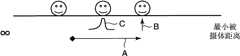
图6是用于说明在所选择的焦点检测区域中进行调焦控制的情况下的操作的图。在图中,横轴表示照相机到被摄体的距离,并且在镜向下状态下的AF单元聚焦于所选择的被摄体之后的镜向上之后,在焦点位置前后进行焦点扫描以检测对比度峰值。在图中,箭头A表示透镜的移动,箭头B所表示的位置处的面部是目标焦点位置,并且波形C表示对比度评价值的峰值(PTL(专利文献)1)。FIG. 6 is a diagram for explaining operations in the case of performing focus control in a selected focus detection area. In the figure, the horizontal axis represents the distance from the camera to the subject, and after the mirror-up after the AF unit in the mirror-down state focuses on the selected subject, focus scanning is performed before and after the focus position to detect contrast peaks . In the figure, arrow A indicates movement of the lens, the face at the position indicated by arrow B is the target focus position, and waveform C indicates the peak value of the contrast evaluation value (PTL (Patent Document) 1).
而且,提出了以下技术:摄像装置的部分像素设置有与其它像素不同的光学特性并且用于焦点检测,以省略传统的用于焦点检测的二次光学系统(PTL(专利文献)2)。Also, a technique has been proposed in which some pixels of an imaging device are provided with different optical characteristics from other pixels and used for focus detection to omit a conventional secondary optical system for focus detection (PTL (Patent Document) 2).
引用列表reference list
专利文献patent documents
PTL 1:日本特开2006-350188PTL 1 : Japanese Patent Laid-Open No. 2006-350188
PTL 2:日本专利3592147PTL 2 : Japanese patent 3592147
发明内容Contents of the invention
技术问题technical problem
然而,在上述PTL 1和PTL 2中,当在多个区域中、即多个点处进行焦点检测时,在焦点检测区域外获得的未选择的焦点检测结果未有效率地用于调焦控制。此外,当进行调焦控制以使得相互接近的多个被摄体进入景深时,可能存在以下情况:目标焦点位置处不存在被摄体并且不能进行基于对比度的焦点检测,或者需要针对多个被摄体中的各被摄体进行基于对比度的焦点检测。However, in the above-mentioned PTL 1 and PTL 2, when focus detection is performed in a plurality of areas, that is, at a plurality of points, non-selected focus detection results obtained outside the focus detection area are not efficiently used for focus control . In addition, when focusing control is performed so that multiple subjects close to each other enter the depth of field, there may be cases where there is no subject at the target focus position and focus detection based on contrast cannot be performed, or it is necessary to focus on multiple subjects. Contrast-based focus detection is performed on each of the subjects.
本发明提供一种可以通过使用多个点处的基于相位差的焦点检测的结果来有效率地获得在基于相位差的焦点检测和基于对比度的焦点检测中获得的焦点位置之间的偏移的摄像设备和用于摄像设备的控制方法。The present invention provides a method that can efficiently obtain a shift between focus positions obtained in phase-difference-based focus detection and contrast-based focus detection by using results of phase-difference-based focus detection at a plurality of points. An imaging device and a control method for the imaging device.
问题的解决方案problem solution
因此,在本发明的第一方面中,提供一种摄像设备,包括:摄像装置,其包括摄像像素组和焦点检测像素组;第一焦点检测单元,用于基于所述焦点检测像素组从不同光瞳获得的一对图像信号,获得多个区域中的焦点位置;第二焦点检测单元,用于检测来自所述摄像像素组的图像信号的对比度处于峰值的、调焦透镜的焦点位置;判断单元,用于从所述第一焦点检测单元获得的多个焦点位置判断目标焦点位置;以及计算单元,用于在当前的焦点位置与所述目标焦点位置之间存在所述第一焦点检测单元所检测到的其它焦点位置的情况下,计算在所述调焦透镜正在移动时所述第二焦点检测单元在所述其它焦点位置处检测到的对比度处于峰值的、所述调焦透镜的焦点位置与所述其它焦点位置之间的偏移。Therefore, in the first aspect of the present invention, an imaging device is provided, including: an imaging device including an imaging pixel group and a focus detection pixel group; A pair of image signals obtained by the pupil to obtain focus positions in a plurality of regions; a second focus detection unit for detecting the focus position of the focus lens at which the contrast of the image signals from the camera pixel group is at a peak value; judging a unit for judging a target focus position from a plurality of focus positions obtained by the first focus detection unit; and a calculation unit for having the first focus detection unit between a current focus position and the target focus position In the case of other detected focus positions, calculating the focus of the focus lens at which the contrast detected by the second focus detection unit at the other focus positions is at a peak when the focus lens is moving The offset between the position and the other focus positions.
因此,在本发明的第二方面中,提供一种用于摄像设备的控制方法,所述摄像设备包括具有摄像像素组和焦点检测像素组的摄像装置,所述控制方法包括:第一焦点检测步骤,用于基于所述焦点检测像素组从不同光瞳获得的一对图像信号,获得多个区域中的焦点位置;第二焦点检测步骤,用于检测来自所述摄像像素组的图像信号的对比度处于峰值的、调焦透镜的焦点位置;第一判断步骤,用于从在所述第一焦点检测步骤中获得的多个焦点位置判断目标焦点位置;第二判断步骤,用于判断在当前的焦点位置与所述目标焦点位置之间是否存在其它焦点位置;以及计算步骤,用于在所述第二判断步骤中判断为存在所述其它焦点位置的情况下,基于如下两个焦点位置来计算焦点位置偏移:基于在所述调焦透镜正在移动时在所述第二焦点检测步骤中在所述其它焦点位置处检测到的对比度的峰值位置所获得的焦点位置;以及根据在所述第一焦点检测步骤中的散焦量所获得的焦点位置。Therefore, in a second aspect of the present invention, there is provided a control method for an imaging device including an imaging device having an imaging pixel group and a focus detection pixel group, the control method comprising: a first focus detection a step of obtaining focus positions in a plurality of regions based on a pair of image signals obtained by the focus detection pixel group from different pupils; a second focus detection step of detecting the position of the image signal from the imaging pixel group The focus position of the focus lens where the contrast is at a peak value; the first judging step is used to judge the target focus position from a plurality of focus positions obtained in the first focus detection step; the second judging step is used to judge the current Whether there are other focus positions between the focus position of the target focus position and the target focus position; and a calculating step, for determining in the second judging step that there are other focus positions, based on the following two focus positions calculating a focus position shift based on the focus position obtained based on the peak position of the contrast detected at the other focus position in the second focus detection step while the focus lens is moving; The focus position obtained by the amount of defocus in the first focus detection step.
发明的有益效果Beneficial Effects of the Invention
根据本发明,可以通过使用多个点处的基于相位差的焦点检测的结果来有效率地获得在基于相位差的焦点检测和基于对比度的焦点检测中获得的焦点位置之间的偏移。According to the present invention, a shift between focus positions obtained in phase difference-based focus detection and contrast-based focus detection can be efficiently obtained by using the results of phase difference-based focus detection at a plurality of points.
通过以下结合附图的详细说明,本发明的特征和优点将变得更加明显。The features and advantages of the present invention will become more apparent through the following detailed description in conjunction with the accompanying drawings.
附图说明Description of drawings
图1是用于说明根据本发明实施例的摄像设备的典型示意结构的框图。FIG. 1 is a block diagram for explaining a typical schematic configuration of an imaging apparatus according to an embodiment of the present invention.
图2A和2B是用于说明摄像设备中的典型自动调焦控制的流程图。2A and 2B are flowcharts for explaining typical autofocus control in an imaging apparatus.
图3是示出在显示单元上显示的9个AF区域中各自的焦点位置的典型布局的图。FIG. 3 is a diagram showing a typical layout of respective focus positions in nine AF areas displayed on the display unit.
图4A~4C是用于说明目标焦点位置判断处理的图。4A to 4C are diagrams for explaining target focus position determination processing.
图5A~5C是用于说明目标焦点位置判断处理的图。5A to 5C are diagrams for explaining target focus position determination processing.
图6是用于说明根据现有技术的在仅在所选择的焦点检测区域中进行调焦控制的情况下的操作的图。FIG. 6 is a diagram for explaining an operation in a case where focus control is performed only in a selected focus detection area according to the related art.
图7是示出在特定的行中包括焦点检测传感器的摄像装置的典型像素配置的图。FIG. 7 is a diagram showing a typical pixel configuration of an imaging device including a focus detection sensor in a specific row.
图8是示意性示出焦点检测传感器S 1的结构的图。FIG. 8 is a diagram schematically showing the structure of the focus detection sensor S1.
图9是示意性示出焦点检测传感器S2的结构的图。FIG. 9 is a diagram schematically showing the structure of the focus detection sensor S2.
图10A和10B是用于说明由于聚焦偏移而引起的图像的相位偏移的图。10A and 10B are diagrams for explaining a phase shift of an image due to a focus shift.
具体实施方式Detailed ways
现在将参考附图详细说明本发明的实施例。Embodiments of the present invention will now be described in detail with reference to the accompanying drawings.
图1是用于说明根据本发明实施例的摄像设备的典型示意结构的框图。FIG. 1 is a block diagram for explaining a typical schematic configuration of an imaging apparatus according to an embodiment of the present invention.
参考图1,根据本实施例的摄像设备100具有用于对被摄体聚焦的调焦透镜101、用于控制调焦透镜101的焦点位置的透镜控制单元102、和用于控制入射光量的光圈103。摄像设备100还具有包括CMOS或CCD等的摄像装置104。Referring to FIG. 1 , an
摄像装置104具有摄像像素组105、焦点检测像素组106和光瞳分割光学系统107。The
摄像像素组105具有在光接收面上设置有R、G和B的颜色滤波器的并且用于获得摄像用的图像信号的多个像素。焦点检测像素组106具有位于多个焦点检测区域、关于光轴对称设置并且具有不同光学特性的多对焦点检测传感器(参见图7~10B)。焦点检测像素组106的视野由遮光层503和603限制(参见图8和9)。光瞳分割光学系统107限制入射光线以使得可以针对焦点检测像素组106的一对焦点检测传感器而关于光轴对称地分割光瞳。The
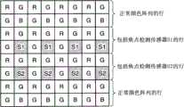
更具体地,可以将至少一对焦点检测传感器设置在摄像装置104的部分像素中。图7是示出在特定的行中包括焦点检测传感器的摄像装置的典型像素配置的图。参考图7,符号R、G和B表示在光线入射至的摄像装置的入射面上分别设置有红色滤波器、绿色滤波器和蓝色滤波器的像素。符号S1和S2表示具有不同光学特性的焦点检测传感器。More specifically, at least one pair of focus detection sensors may be provided in some pixels of the
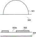
图8是示意性示出焦点检测传感器S1的结构的图。参考图8,焦点检测传感器S1具有微透镜501、平滑层502、遮光层503和光电转换元件504。将微透镜501设置在顶部,并且平滑层502构成形成微透镜501的平面。遮光层503具有相对于像素的光电转换区域的中心偏心至一侧的开口503a,并且具有减少入射光线的功能。FIG. 8 is a diagram schematically showing the structure of the focus detection sensor S1. Referring to FIG. 8 , the focus detection sensor S1 has a
图9是示意性示出焦点检测传感器S2的结构的图。参考图9,焦点检测传感器S2与焦点检测传感器S1一样具有微透镜601、平滑层602、遮光层603和光电转换元件604。焦点检测传感器S2与焦点检测传感器S1的不同之处在于遮光层603的开口603a相对于像素的光电转换区域的中心偏心至另一侧。FIG. 9 is a diagram schematically showing the structure of the focus detection sensor S2. Referring to FIG. 9 , the focus detection sensor S2 has a
参考图7,将包括焦点检测传感器S1的行和包括焦点检测传感器S2的行设置得相互接近,并且它们形成基本上相同的图像信号。当经由摄像光学系统将被摄体光聚焦在像素上时,来自包括焦点检测传感器S1的行的图像信号和来自包括焦点检测传感器S2的行的图像信号相互一致。Referring to FIG. 7, the row including the focus detection sensor S1 and the row including the focus detection sensor S2 are arranged close to each other, and they form substantially the same image signal. When subject light is focused on the pixels via the imaging optical system, image signals from the row including the focus detection sensor S1 and image signals from the row including the focus detection sensor S2 agree with each other.
在被摄体光失焦的情况下,在来自包括焦点检测传感器S1的行的图像信号和来自包括焦点检测传感器S 2的行的图像信号之间生成相位差。前方聚焦状态和后方聚焦状态下的相位差的方向相反。In the case where the subject light is out of focus, a phase difference is generated between the image signal from the row including the focus detection sensor S1 and the image signal from the row including the focus detection sensor S2. The direction of the phase difference in the front focus state and the rear focus state is opposite.
当从焦点检测传感器S1和焦点检测传感器S2观看摄像光学系统时,光瞳看上去关于光学中心被对称分割。When viewing the imaging optical system from the focus detection sensor S1 and the focus detection sensor S2 , the pupil appears to be divided symmetrically about the optical center.
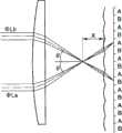
图10A和10B是用于说明由于聚焦偏移而引起的图像的相位偏移的图。在图10A和10B中,由符号A和B分别表示与图7中出现的焦点检测传感器S1和焦点检测传感器S2相对应的部分,并且为了便于说明,未示出用于摄像的RGB像素,并且并列排列焦点检测传感器。10A and 10B are diagrams for explaining a phase shift of an image due to a focus shift. In FIGS. 10A and 10B , parts corresponding to the focus detection sensor S1 and the focus detection sensor S2 appearing in FIG. 7 are denoted by symbols A and B, respectively, and for convenience of explanation, RGB pixels for imaging are not shown, and Focus detection sensors are arranged side by side.
将来自被摄体上的特定点的光分割成通过与部分A相对应的光瞳而入射到部分A的光线束(ΦLa)和通过与部分B相对应的光瞳而入射到部分B的光线束(ΦLb)。因为这两个光线束来自同一个点,因此只要将摄像光学系统聚焦在摄像装置上就能到达同一微透镜上的一个点(图10A)。然而,例如,当摄像光学系统的焦点在摄像装置之前的x处时,两个光线束偏移了光线的入射角的变化(图10B),并且当摄像光学系统的焦点在摄像装置之后的x处时,两个光线束在反方向上偏移。Divides light from a specific point on the subject into a ray bundle (ΦLa) that enters part A through the pupil corresponding to part A and light that enters part B through the pupil corresponding to part B Harness (ΦLb). Because the two light beams come from the same point, they can reach a point on the same microlens as long as the imaging optical system is focused on the imaging device (FIG. 10A). However, for example, when the focal point of the imaging optical system is at x in front of the imaging device, the two ray bundles are offset by the change in the incident angle of the light rays (Fig. 10B), and when the focal point of the imaging optical system is at x behind the imaging device At , the two beams of light are shifted in opposite directions.
由此,当摄像光学系统聚焦时,在行A中形成的图像信号和在行B中形成的图像信号相互一致,并且当摄像光学系统失焦时,在行A中形成的图像信号和在行B中形成的图像信号相互不一致。Thus, when the imaging optical system is in focus, the image signal formed in line A and the image signal formed in line B coincide with each other, and when the imaging optical system is out of focus, the image signal formed in line A and the image signal formed in line B coincide with each other. The image signals formed in B do not agree with each other.
根据本实施例的摄像设备100还具有焦点检测单元108、对比度检测单元109、像素插值单元110、图像处理单元111、显示单元112、记录单元113、操作单元114和照相机控制单元115。The
焦点检测单元108通过进行相关计算来计算焦点检测像素组106中的一对焦点检测传感器S1和S2的像素行之间的图像偏移量,以检测焦点位置。对比度检测单元109使用来自摄像像素组105的图像信号来输出对比度评价值。像素插值单元110根据附近的像素组对与焦点检测像素组106中的像素的位置相对应的摄像用的图像数据进行插值。The
图像处理单元111对从摄像像素组105输出的图像信号进行伽玛校正、白平衡调节、再采样、预定图像压缩编码。显示单元112显示从图像处理单元111输出的图像数据,并且记录单元113记录从图像处理单元111输出的图像数据。操作单元114接收用户的操作输入。照相机控制单元115控制摄像设备100的整体操作,并且例如控制透镜控制单元102移动透镜,并且根据来自对比度检测单元109的输出来进行基于对比度的AF。The
接着参考图2A和2B,将说明根据本实施例的摄像设备100中的典型自动调焦控制。通过照相机控制单元115的CPU等根据存储在未示出的ROM或HDD等中的并且载入RAM中的程序来执行图2A和2B中的各处理。Referring next to FIGS. 2A and 2B , typical autofocus control in the
在步骤S11中,照相机控制单元115从焦点检测像素组106读取信号,并且进入步骤S12。In step S11, the
在步骤S12中,照相机控制单元115使得焦点检测单元108对如参考图10A和10B所述焦点检测像素组106的一对焦点检测传感器S1和S2从不同光瞳获得的两个图像信号进行相关计算。结果,照相机控制单元115获得焦点位置,并且进入步骤S13。In step S12, the
在该情况下,例如,如图3所示,照相机控制单元115在显示单元112上显示9个AF区域中各自的焦点位置。在图3所示的例子中,在左上、中心和右中处存在人脸,并且获得其焦点位置。In this case, for example, the
在步骤S13中,照相机控制单元115基于步骤S12中获得的多个AF区域的焦点位置的信息来判断目标焦点位置,并且进入步骤S14。In step S13, the
现在将参考图4A~4C说明目标焦点位置判断处理。图4A~4C示出画面上存在的三个人之间的位置关系的典型的三个图案,其中横轴表示照相机到被摄体的距离,左边表示无限距离,并且右边表示最小被摄体距离。而且,箭头A表示调焦透镜101的移动,箭头B所表示的位置处的面部是目标焦点位置,并且波形C表示对比度评价值的峰值。The target focus position determination processing will now be described with reference to FIGS. 4A to 4C . 4A to 4C show typical three patterns of the positional relationship between three people present on the screen, where the horizontal axis represents the distance from the camera to the subject, the left represents the infinite distance, and the right represents the minimum subject distance. Also, arrow A indicates the movement of the
参考图4A,因为三个人相距基本上相等的距离,因而判断为这三个人是不相关的人,并且将最近的人或位于中间的人判断为目标焦点位置。在该示例中,选择最近的人。Referring to FIG. 4A , since three people are separated by substantially equal distances, it is judged that the three people are unrelated people, and the closest person or a person in the middle is judged as a target focus position. In this example, nearest people is selected.
参考图4B,因为三个人相对地相互靠近,因而可以判断为这是集体照相,并且在该情况下,将全部三个人的焦点位置位于景深内的位置判断为目标焦点位置。Referring to FIG. 4B , since the three people are relatively close to each other, it can be judged that this is group photography, and in this case, a position where the focus positions of all three people are within the depth of field is judged as the target focus position.
参考图4C,因为两个人相互靠近,因而判断为他们是相关的人,并且因为另一个人远离这两个人,因而判断为他/她是不相关的人。在该情况下,将相互靠近的两个人位于景深内的位置判断为目标焦点位置。Referring to FIG. 4C , two persons are judged to be related persons because they are close to each other, and another person is judged to be an unrelated person because he/she is far away from the two persons. In this case, a position where two persons approaching each other are located within the depth of field is determined as the target focus position.
在步骤S14中,照相机控制单元115判断当前的焦点位置Dn和目标焦点位置Dt之间是否存在其它焦点位置Dm,并且当焦点位置Dm存在时,照相机控制单元115进入步骤S19,并且当焦点位置Dm不存在时,照相机控制单元115进入步骤S15。In step S14, the
在步骤S19中,照相机控制单元115使得透镜控制单元102沿着光轴移动调焦透镜并且偏移焦点位置,并且进入步骤S20。In step S19, the
在步骤S20中,照相机控制单元115使得对比度检测单元109获得在调焦透镜101正在移动时存在的焦点位置Dm处的被摄体的峰值位置,并且通过对峰值位置进行插值来获得焦点位置Dmc,并且进入步骤S21。In step S20, the
在步骤S21中,照相机控制单元115在焦点位置Dm处从焦点检测像素组106读取信号,并且以与上述方式相同的方式使得焦点检测单元108再次获得被摄体的焦点位置Dmp,然后进入步骤S22。步骤S20和步骤S21中获得的焦点位置必须仅处于在当前的焦点位置Dn和目标焦点位置Dt之间存在的焦点位置Dm的附近。而且,在步骤S21中,从基于相位差的AF的散焦量获得焦点位置Dmp。In step S21, the
在步骤S22中,照相机控制单元115使得焦点检测单元108以与上述方式相同的方式在目标焦点位置Dt之前再次获得被摄体的焦点位置Dt’,然后进入步骤S23。因为在目标焦点位置Dt的附近获得焦点位置Dt’的值,因而可以进一步提高精确度。In step S22, the
在步骤S23中,照相机控制单元115根据从步骤S20和步骤S21中获得的焦点位置Dmc和Dmp计算偏移,校正步骤S22中获得的焦点位置Dt’以获得焦点位置Dt”,然后进入步骤S24。In step S23, the
在步骤S24中,照相机控制单元115控制透镜控制单元102在步骤S23中获得的焦点位置Dt”处停止移动调焦透镜101,并且结束处理。应当注意,可以在步骤S21和步骤S24之间将步骤S22和步骤S23中的处理重复进行预定次数。步骤S19~S24中的操作与图4A、4C和5B相对应。In step S24, the
另一方面,在步骤S15中,照相机控制单元115使得透镜控制单元102沿着光轴移动调焦透镜101并且移动焦点位置,并且进入步骤S16。On the other hand, in step S15, the
在步骤S16中,照相机控制单元115通过根据目标焦点位置Dt处的对比度检测单元109的输出而检测峰值位置来获得焦点位置Dc,并且进入步骤S17。In step S16, the
在步骤S17中,照相机控制单元115使得透镜控制单元102反转调焦透镜101的移动方向,并且进入步骤S18。In step S17, the
在步骤S18中,照相机控制单元115使得透镜控制单元102在步骤S16中获得的焦点位置Dc处停止移动调焦透镜101,并且结束处理。应当注意,步骤S15~S18中的操作与图4B、5A和5C相对应。图4B和5C示出目标焦点位置被设置为使得多个被摄体可以位于景深内的状态,但是可以通过从一个被摄体获得偏移来提供控制。In step S18, the
如上所述,根据本实施例,使用多个点处的基于相位差的AF的结果来确定目标焦点位置,在移动透镜的同时在存在被摄体的区域中进行基于对比度的AF,并且获得焦点位置偏移。由此,可以省略用于在目标焦点位置处检测峰值位置的调焦控制,并且可以节省在峰值的检测之后反转透镜移动方向的时间。结果,可以通过使用多个点处的基于相位差的AF的结果来有效率地获得基于相位差的AF的焦点位置和基于对比度的AF的焦点位置之间的偏移。As described above, according to the present embodiment, the target focus position is determined using the results of phase difference-based AF at a plurality of points, contrast-based AF is performed in an area where a subject exists while moving the lens, and focus is obtained position offset. Thereby, focus control for detecting the peak position at the target focus position can be omitted, and time for reversing the lens moving direction after detection of the peak can be saved. As a result, the shift between the focus position of phase difference based AF and the focus position of contrast based AF can be efficiently obtained by using the results of phase difference based AF at a plurality of points.
此外,即使在将不同距离处的多个被摄体控制在景深内时的目标焦点位置处不能进行基于对比度的AF的情况下,也可以使用目标焦点位置的附近的焦点位置,因此可以以高精度进行调焦控制。Also, even in the case where contrast-based AF cannot be performed at the target focus position when controlling multiple subjects at different distances within the depth of field, a focus position near the target focus position can be used, so it is possible to achieve a high Accurate focus control.
应当注意,本发明不限于上述实施例,但可以在不背离本发明的精神的情况下对上述实施例做出各种改变。It should be noted that the present invention is not limited to the above-described embodiments, but various changes can be made to the above-described embodiments without departing from the spirit of the invention.
其它实施例other embodiments
还可以利用读出并且执行记录在存储器装置上的程序以进行上述实施例的功能的系统或设备的计算机(或者CPU或MPU等装置)和通过下面的方法实现本发明的方面,其中,利用系统或设备的计算机通过例如读出并且执行记录在存储器装置上的程序以进行上述实施例的功能来进行上述方法的步骤。为此,例如,通过网络或者通过用作存储器装置的各种类型的记录介质(例如,计算机可读介质)将该程序提供给计算机。It is also possible to use a computer (or a device such as a CPU or an MPU) of a system or device that reads and executes a program recorded on a memory device to perform the functions of the above-mentioned embodiments and implement the aspects of the present invention by the following method, wherein, using the system Or the computer of the device performs the steps of the above method by, for example, reading and executing the program recorded on the memory device to perform the functions of the above embodiments. For this purpose, the program is supplied to the computer via a network or via various types of recording media (for example, computer-readable media) serving as memory means, for example.
尽管已经参考典型实施例说明了本发明,但是应该理解,本发明不限于所公开的典型实施例。所附权利要求书的范围符合最宽的解释,以包含所有这类修改、等同结构和功能。While the present invention has been described with reference to exemplary embodiments, it is to be understood that the invention is not limited to the disclosed exemplary embodiments. The scope of the appended claims is to be accorded the broadest interpretation to encompass all such modifications and equivalent structures and functions.
附图标记列表List of reference signs
100 摄像设备100 camera equipment
101 调焦透镜101 focus lens
102 透镜控制单元102 Lens control unit
105 摄像像素组105 camera pixel groups
106 焦点检测像素组106 focus detection pixel groups
107 光瞳分割光学系统107 pupil split optical system
108 焦点检测单元108 focus detection unit
109 对比度检测单元109 contrast detection unit
110 像素插值单元110 pixel interpolation unit
111 图像处理单元111 image processing unit
115 照相机控制单元115 Camera control unit
Claims (4)
Translated fromChineseApplications Claiming Priority (3)
| Application Number | Priority Date | Filing Date | Title |
|---|---|---|---|
| JP2009-174444 | 2009-07-27 | ||
| JP2009174444AJP5448621B2 (en) | 2009-07-27 | 2009-07-27 | IMAGING DEVICE AND IMAGING DEVICE CONTROL METHOD |
| PCT/JP2010/062736WO2011013725A1 (en) | 2009-07-27 | 2010-07-22 | Image pickup apparatus that performs automatic focus control and control method for the image pickup apparatus |
Publications (2)
| Publication Number | Publication Date |
|---|---|
| CN102472882A CN102472882A (en) | 2012-05-23 |
| CN102472882Btrue CN102472882B (en) | 2014-02-26 |
Family
ID=43529377
Family Applications (1)
| Application Number | Title | Priority Date | Filing Date |
|---|---|---|---|
| CN201080033778.2AExpired - Fee RelatedCN102472882B (en) | 2009-07-27 | 2010-07-22 | Imaging device for performing automatic focus control and method for controlling the imaging device |
Country Status (4)
| Country | Link |
|---|---|
| US (1) | US8736742B2 (en) |
| JP (1) | JP5448621B2 (en) |
| CN (1) | CN102472882B (en) |
| WO (1) | WO2011013725A1 (en) |
Families Citing this family (10)
| Publication number | Priority date | Publication date | Assignee | Title |
|---|---|---|---|---|
| JP5808124B2 (en)* | 2011-03-24 | 2015-11-10 | キヤノン株式会社 | FOCUS DETECTION DEVICE, ITS CONTROL METHOD, AND IMAGING DEVICE HAVING FOCUS DETECTION DEVICE |
| JP5904714B2 (en)* | 2011-03-25 | 2016-04-20 | キヤノン株式会社 | FOCUS DETECTION DEVICE, ITS CONTROL METHOD, AND IMAGING DEVICE HAVING FOCUS DETECTION DEVICE |
| JP2014085608A (en)* | 2012-10-26 | 2014-05-12 | Nikon Corp | Imaging device |
| JP6239862B2 (en)* | 2013-05-20 | 2017-11-29 | キヤノン株式会社 | Focus adjustment apparatus, focus adjustment method and program, and imaging apparatus |
| CN103808733A (en)* | 2014-03-04 | 2014-05-21 | 致茂电子(苏州)有限公司 | Focusing method of automatic optical detection device |
| JP6346793B2 (en)* | 2014-06-03 | 2018-06-20 | オリンパス株式会社 | IMAGING DEVICE, IMAGING DEVICE CONTROL METHOD, AND PROGRAM |
| US9681038B2 (en)* | 2014-09-15 | 2017-06-13 | Lg Electronics Inc. | Mobile terminal and method for setting a focal point value |
| JP6646676B2 (en)* | 2015-09-08 | 2020-02-14 | ギガフォトン株式会社 | Extreme ultraviolet light generator |
| JP6637155B2 (en)* | 2016-02-26 | 2020-01-29 | ギガフォトン株式会社 | Extreme ultraviolet light generator |
| CN106791119B (en)* | 2016-12-27 | 2020-03-27 | 努比亚技术有限公司 | Photo processing method and device and terminal |
Citations (3)
| Publication number | Priority date | Publication date | Assignee | Title |
|---|---|---|---|---|
| JP2006171381A (en)* | 2004-12-16 | 2006-06-29 | Canon Inc | camera |
| JP2007148242A (en)* | 2005-11-30 | 2007-06-14 | Konica Minolta Photo Imaging Inc | Focusing controller, and imaging apparatus |
| CN101126833A (en)* | 2006-08-16 | 2008-02-20 | 佳能株式会社 | Automatic focusing apparatus and image pickup apparatus |
Family Cites Families (9)
| Publication number | Priority date | Publication date | Assignee | Title |
|---|---|---|---|---|
| DE19710753C2 (en)* | 1996-03-15 | 2000-11-23 | Asahi Optical Co Ltd | Automatic focusing device |
| JP3592147B2 (en) | 1998-08-20 | 2004-11-24 | キヤノン株式会社 | Solid-state imaging device |
| JP2003295047A (en)* | 2002-04-05 | 2003-10-15 | Canon Inc | Imaging device and imaging system |
| EP1684503B1 (en)* | 2005-01-25 | 2016-01-13 | Canon Kabushiki Kaisha | Camera and autofocus control method therefor |
| JP2006350188A (en) | 2005-06-20 | 2006-12-28 | Nikon Corp | Autofocus device |
| WO2008001575A1 (en)* | 2006-06-28 | 2008-01-03 | Nikon Corporation | Tracking device, automatic focusing device, and camera |
| JP5094068B2 (en)* | 2006-07-25 | 2012-12-12 | キヤノン株式会社 | Imaging apparatus and focus control method |
| JP5247044B2 (en)* | 2007-02-16 | 2013-07-24 | キヤノン株式会社 | Imaging device |
| JP2009115893A (en)* | 2007-11-02 | 2009-05-28 | Canon Inc | Imaging device |
- 2009
- 2009-07-27JPJP2009174444Apatent/JP5448621B2/ennot_activeExpired - Fee Related
- 2010
- 2010-07-22CNCN201080033778.2Apatent/CN102472882B/ennot_activeExpired - Fee Related
- 2010-07-22WOPCT/JP2010/062736patent/WO2011013725A1/enactiveApplication Filing
- 2010-07-22USUS13/319,888patent/US8736742B2/ennot_activeExpired - Fee Related
Patent Citations (3)
| Publication number | Priority date | Publication date | Assignee | Title |
|---|---|---|---|---|
| JP2006171381A (en)* | 2004-12-16 | 2006-06-29 | Canon Inc | camera |
| JP2007148242A (en)* | 2005-11-30 | 2007-06-14 | Konica Minolta Photo Imaging Inc | Focusing controller, and imaging apparatus |
| CN101126833A (en)* | 2006-08-16 | 2008-02-20 | 佳能株式会社 | Automatic focusing apparatus and image pickup apparatus |
Also Published As
| Publication number | Publication date |
|---|---|
| JP5448621B2 (en) | 2014-03-19 |
| CN102472882A (en) | 2012-05-23 |
| US8736742B2 (en) | 2014-05-27 |
| US20120113313A1 (en) | 2012-05-10 |
| JP2011028048A (en) | 2011-02-10 |
| WO2011013725A1 (en) | 2011-02-03 |
Similar Documents
| Publication | Publication Date | Title |
|---|---|---|
| CN102472882B (en) | Imaging device for performing automatic focus control and method for controlling the imaging device | |
| US8730373B2 (en) | Image forming apparatus | |
| US9742984B2 (en) | Image capturing apparatus and method of controlling the same | |
| JP5361535B2 (en) | Imaging device | |
| KR101917403B1 (en) | Image pickup apparatus, image pickup device, image processing method, aperture control method, and program | |
| JP5753371B2 (en) | Imaging apparatus and control method thereof | |
| JP6506560B2 (en) | Focus control device and method therefor, program, storage medium | |
| KR20130011424A (en) | Apparatus and method for controlling focus by image sensor for outputting phase difference signal | |
| JP6045214B2 (en) | Focus adjustment apparatus and control method thereof | |
| JP6548435B2 (en) | Display control apparatus, control method therefor, and imaging apparatus | |
| JP6952222B2 (en) | Imaging device | |
| US20120099006A1 (en) | Image pickup apparatus | |
| US9602716B2 (en) | Focus-detection device, method for controlling the same, and image capture apparatus | |
| JP6486041B2 (en) | Imaging apparatus and control method thereof | |
| JP2017032646A (en) | Imaging apparatus and control method thereof | |
| JPWO2019202984A1 (en) | Imaging device and distance measurement method, distance measurement program and recording medium | |
| US20240171855A1 (en) | Accuracy estimation apparatus, image capturing apparatus, accuracy estimation method, control method, and storage medium that provide a notification based on an accuracy | |
| JP6854619B2 (en) | Focus detection device and method, imaging device, lens unit and imaging system | |
| JP2020008415A (en) | Distance measuring camera | |
| JP5207893B2 (en) | Imaging apparatus and control method thereof | |
| JP6257201B2 (en) | FOCUS DETECTION DEVICE, ITS CONTROL METHOD, CONTROL PROGRAM, AND IMAGING DEVICE | |
| JP2016051084A (en) | Imaging device and image pick-up element | |
| JP7019442B2 (en) | Image pickup device and its control method | |
| JP7207874B2 (en) | CONTROL DEVICE, IMAGING DEVICE, CONTROL METHOD, PROGRAM, AND STORAGE MEDIUM | |
| JP2020101723A (en) | Imaging apparatus |
Legal Events
| Date | Code | Title | Description |
|---|---|---|---|
| C06 | Publication | ||
| PB01 | Publication | ||
| C10 | Entry into substantive examination | ||
| SE01 | Entry into force of request for substantive examination | ||
| C14 | Grant of patent or utility model | ||
| GR01 | Patent grant | ||
| CF01 | Termination of patent right due to non-payment of annual fee | Granted publication date:20140226 | |
| CF01 | Termination of patent right due to non-payment of annual fee |