CN102472589A - Compact evaporator for chillers - Google Patents
Compact evaporator for chillersDownload PDFInfo
- Publication number
- CN102472589A CN102472589ACN2010800300468ACN201080030046ACN102472589ACN 102472589 ACN102472589 ACN 102472589ACN 2010800300468 ACN2010800300468 ACN 2010800300468ACN 201080030046 ACN201080030046 ACN 201080030046ACN 102472589 ACN102472589 ACN 102472589A
- Authority
- CN
- China
- Prior art keywords
- suction
- housing
- inlet
- tube
- wall
- Prior art date
- Legal status (The legal status is an assumption and is not a legal conclusion. Google has not performed a legal analysis and makes no representation as to the accuracy of the status listed.)
- Granted
Links
Images


Classifications
- F—MECHANICAL ENGINEERING; LIGHTING; HEATING; WEAPONS; BLASTING
- F28—HEAT EXCHANGE IN GENERAL
- F28D—HEAT-EXCHANGE APPARATUS, NOT PROVIDED FOR IN ANOTHER SUBCLASS, IN WHICH THE HEAT-EXCHANGE MEDIA DO NOT COME INTO DIRECT CONTACT
- F28D7/00—Heat-exchange apparatus having stationary tubular conduit assemblies for both heat-exchange media, the media being in contact with different sides of a conduit wall
- F28D7/16—Heat-exchange apparatus having stationary tubular conduit assemblies for both heat-exchange media, the media being in contact with different sides of a conduit wall the conduits being arranged in parallel spaced relation
- F—MECHANICAL ENGINEERING; LIGHTING; HEATING; WEAPONS; BLASTING
- F25—REFRIGERATION OR COOLING; COMBINED HEATING AND REFRIGERATION SYSTEMS; HEAT PUMP SYSTEMS; MANUFACTURE OR STORAGE OF ICE; LIQUEFACTION SOLIDIFICATION OF GASES
- F25B—REFRIGERATION MACHINES, PLANTS OR SYSTEMS; COMBINED HEATING AND REFRIGERATION SYSTEMS; HEAT PUMP SYSTEMS
- F25B39/00—Evaporators; Condensers
- F25B39/02—Evaporators
- F—MECHANICAL ENGINEERING; LIGHTING; HEATING; WEAPONS; BLASTING
- F28—HEAT EXCHANGE IN GENERAL
- F28D—HEAT-EXCHANGE APPARATUS, NOT PROVIDED FOR IN ANOTHER SUBCLASS, IN WHICH THE HEAT-EXCHANGE MEDIA DO NOT COME INTO DIRECT CONTACT
- F28D21/00—Heat-exchange apparatus not covered by any of the groups F28D1/00 - F28D20/00
- F28D21/0017—Flooded core heat exchangers
- F—MECHANICAL ENGINEERING; LIGHTING; HEATING; WEAPONS; BLASTING
- F28—HEAT EXCHANGE IN GENERAL
- F28D—HEAT-EXCHANGE APPARATUS, NOT PROVIDED FOR IN ANOTHER SUBCLASS, IN WHICH THE HEAT-EXCHANGE MEDIA DO NOT COME INTO DIRECT CONTACT
- F28D3/00—Heat-exchange apparatus having stationary conduit assemblies for one heat-exchange medium only, the media being in contact with different sides of the conduit wall, in which the other heat-exchange medium flows in a continuous film, or trickles freely, over the conduits
- F28D3/02—Heat-exchange apparatus having stationary conduit assemblies for one heat-exchange medium only, the media being in contact with different sides of the conduit wall, in which the other heat-exchange medium flows in a continuous film, or trickles freely, over the conduits with tubular conduits
- F—MECHANICAL ENGINEERING; LIGHTING; HEATING; WEAPONS; BLASTING
- F28—HEAT EXCHANGE IN GENERAL
- F28F—DETAILS OF HEAT-EXCHANGE AND HEAT-TRANSFER APPARATUS, OF GENERAL APPLICATION
- F28F9/00—Casings; Header boxes; Auxiliary supports for elements; Auxiliary members within casings
- F28F9/005—Other auxiliary members within casings, e.g. internal filling means or sealing means
- F—MECHANICAL ENGINEERING; LIGHTING; HEATING; WEAPONS; BLASTING
- F28—HEAT EXCHANGE IN GENERAL
- F28F—DETAILS OF HEAT-EXCHANGE AND HEAT-TRANSFER APPARATUS, OF GENERAL APPLICATION
- F28F9/00—Casings; Header boxes; Auxiliary supports for elements; Auxiliary members within casings
- F28F9/22—Arrangements for directing heat-exchange media into successive compartments, e.g. arrangements of guide plates
- F—MECHANICAL ENGINEERING; LIGHTING; HEATING; WEAPONS; BLASTING
- F25—REFRIGERATION OR COOLING; COMBINED HEATING AND REFRIGERATION SYSTEMS; HEAT PUMP SYSTEMS; MANUFACTURE OR STORAGE OF ICE; LIQUEFACTION SOLIDIFICATION OF GASES
- F25B—REFRIGERATION MACHINES, PLANTS OR SYSTEMS; COMBINED HEATING AND REFRIGERATION SYSTEMS; HEAT PUMP SYSTEMS
- F25B2339/00—Details of evaporators; Details of condensers
- F25B2339/02—Details of evaporators
- F25B2339/024—Evaporators with refrigerant in a vessel in which is situated a heat exchanger
- F25B2339/0242—Evaporators with refrigerant in a vessel in which is situated a heat exchanger having tubular elements
- F—MECHANICAL ENGINEERING; LIGHTING; HEATING; WEAPONS; BLASTING
- F25—REFRIGERATION OR COOLING; COMBINED HEATING AND REFRIGERATION SYSTEMS; HEAT PUMP SYSTEMS; MANUFACTURE OR STORAGE OF ICE; LIQUEFACTION SOLIDIFICATION OF GASES
- F25B—REFRIGERATION MACHINES, PLANTS OR SYSTEMS; COMBINED HEATING AND REFRIGERATION SYSTEMS; HEAT PUMP SYSTEMS
- F25B2500/00—Problems to be solved
- F25B2500/28—Means for preventing liquid refrigerant entering into the compressor
- F—MECHANICAL ENGINEERING; LIGHTING; HEATING; WEAPONS; BLASTING
- F28—HEAT EXCHANGE IN GENERAL
- F28D—HEAT-EXCHANGE APPARATUS, NOT PROVIDED FOR IN ANOTHER SUBCLASS, IN WHICH THE HEAT-EXCHANGE MEDIA DO NOT COME INTO DIRECT CONTACT
- F28D21/00—Heat-exchange apparatus not covered by any of the groups F28D1/00 - F28D20/00
- F28D2021/0019—Other heat exchangers for particular applications; Heat exchange systems not otherwise provided for
- F28D2021/0068—Other heat exchangers for particular applications; Heat exchange systems not otherwise provided for for refrigerant cycles
- F28D2021/0071—Evaporators
- F—MECHANICAL ENGINEERING; LIGHTING; HEATING; WEAPONS; BLASTING
- F28—HEAT EXCHANGE IN GENERAL
- F28F—DETAILS OF HEAT-EXCHANGE AND HEAT-TRANSFER APPARATUS, OF GENERAL APPLICATION
- F28F9/00—Casings; Header boxes; Auxiliary supports for elements; Auxiliary members within casings
- F28F9/22—Arrangements for directing heat-exchange media into successive compartments, e.g. arrangements of guide plates
- F28F2009/222—Particular guide plates, baffles or deflectors, e.g. having particular orientation relative to an elongated casing or conduit
Landscapes
- Engineering & Computer Science (AREA)
- Physics & Mathematics (AREA)
- Thermal Sciences (AREA)
- Mechanical Engineering (AREA)
- General Engineering & Computer Science (AREA)
- Heat-Exchange Devices With Radiators And Conduit Assemblies (AREA)
Abstract
Translated fromChinese
Description
Translated fromChinese相关专利申请的相互参引Cross-references to related patent applications
本申请要求于2009年7月22日提交的标题为“EVAPORATOR(蒸发器)”的第61/227,640号美国临时申请的优先权和权益,该美国临时申请以参引的方式纳入本文。This application claims priority to and benefit of US Provisional Application No. 61/227,640, filed July 22, 2009, entitled "EVAPORATOR," which is incorporated herein by reference.
背景技术Background technique
蒸发器可被用在各种系统中,包括蒸气压缩冷冻机系统中,该蒸气压缩冷冻机系统的基本部件包括压缩机、冷凝器、膨胀装置和蒸发器。冷冻机系统的主要部件被相互连接,以形成常规闭环制冷回路。Evaporators can be used in a variety of systems, including vapor compression refrigerator systems, the basic components of which include a compressor, condenser, expansion device, and evaporator. The main components of the freezer system are interconnected to form a conventional closed-loop refrigeration circuit.
在蒸气压缩冷冻机系统的基本运作中,压缩机通过排放管线将已压缩的气态制冷剂排放至冷凝器,在所述冷凝器中冷却流体冷却和冷凝该制冷剂。已冷凝的制冷剂从冷凝器传递至膨胀装置,在该膨胀装置中,通过膨胀来冷却所述制冷剂,之后所述制冷剂作为液体和蒸气制冷剂的两相混合物进入蒸发器的蒸发器入口。所述两相制冷剂混合物被分布掠过(across)设置在蒸发器的壳体(shell)内的管束。所述制冷剂在多个管之间流动,并且附带掠过所述管束的多个管的外部,冷却穿过所述管束的多个管的内部的热吸收流体。所述热吸收流体通常是水或水/乙二醇混合物。出于本文讨论的目的,假设所述流体是水。针对各种冷却目的,已变冷的水可随后被泵送至远方位置。In basic operation of a vapor compression refrigerator system, a compressor discharges compressed gaseous refrigerant through a discharge line to a condenser where a cooling fluid cools and condenses the refrigerant. The condensed refrigerant is passed from the condenser to an expansion device where it is cooled by expansion before it enters the evaporator inlet of the evaporator as a two-phase mixture of liquid and vapor refrigerant . The two-phase refrigerant mixture is distributed across a bundle of tubes disposed within the shell of the evaporator. The refrigerant flows between the plurality of tubes and incidentally skims the exterior of the plurality of tubes of the tube bundle, cooling the heat absorbing fluid passing through the interior of the plurality of tubes of the tube bundle. The heat absorbing fluid is typically water or a water/glycol mixture. For the purposes of this discussion, it is assumed that the fluid is water. The chilled water can then be pumped to remote locations for various cooling purposes.
该已变冷的水使经过并掠过管束的制冷剂混合物的液体部分蒸发。通过压力差将蒸气制冷剂抽向附接至蒸发器壳体的抽吸入口或蒸发器出口。蒸发器中的隔板有助于确保主要仅制冷剂的蒸气部分被传送至抽吸管的抽吸入口。抽吸管线或管道从该抽吸管将蒸气制冷剂传送至压缩机的入口,使得压缩机可再压缩该制冷剂,以维持该制冷剂循环。This chilled water evaporates the liquid portion of the refrigerant mixture passing over and over the tube bundle. Vapor refrigerant is drawn by a pressure differential towards a suction inlet or evaporator outlet attached to the evaporator shell. Baffles in the evaporator help to ensure that mainly only the vapor portion of the refrigerant is delivered to the suction inlet of the suction pipe. A suction line or pipe carries vapor refrigerant from the suction pipe to the inlet of the compressor so that the compressor can recompress the refrigerant to maintain the refrigerant cycle.
留在蒸发器壳体中的液体制冷剂积在蒸发器的底部。使得液体制冷剂与该管束的浸没在该液体中的部分进行热交换。泵或一些其他常规设备可将液体返回至与蒸发器相关联的任何合适的入口。Liquid refrigerant left in the evaporator shell pools at the bottom of the evaporator. The liquid refrigerant is brought into heat exchange with the portion of the tube bundle submerged in the liquid. A pump or some other conventional device may return the liquid to any suitable inlet associated with the evaporator.
在冷冻机系统中使用的典型蒸发器在抽吸管的入口附近具有抽吸隔板。蒸发器中的抽吸隔板的作用是在冷冻机运作期间使得携带(carry-over)进入抽吸管或抽吸管线中的液体制冷剂最小化。由于该设计约束,常规蒸发器中的抽吸入口和抽吸管被附接在蒸发器的顶部附近,通常直接在抽吸隔板上方,从而增大了蒸发器的高度。A typical evaporator used in a freezer system has a suction baffle near the inlet of the suction tube. The function of the suction baffle in the evaporator is to minimize carry-over of liquid refrigerant into the suction tube or suction line during operation of the refrigerator. Due to this design constraint, the suction inlet and suction pipe in conventional evaporators are attached near the top of the evaporator, usually directly above the suction bulkhead, increasing the height of the evaporator.
典型的蒸发器设计在管束和抽吸隔板之间还包括一个区域,用于使制冷剂微滴(droplet)与蒸气流分离。所述区域(名为微滴脱离区域)还被设计为使得进入抽吸管的液体制冷剂的量最小化。Typical evaporator designs also include an area between the tube bundle and the suction baffle to separate refrigerant droplets from the vapor stream. The zone, named droplet break-off zone, is also designed to minimize the amount of liquid refrigerant entering the suction tube.
小尺寸和小容量的蒸发器所呈现的一个问题是抽吸管的入口相对大,且如果抽吸管的位置太过远离顶部,则将侵入抽吸隔板下方的空间中或微滴脱离区域中。在小尺寸和小容量的蒸发器中,如果抽吸管的入口侵入抽吸隔板下方的空间中,则由于提供了一个直接路径使制冷剂流入该抽吸管入口而导致液体携带进入抽吸管,从而降低或消除了抽吸隔板的有效性。在该有问题的设计中,抽吸管入口绕过抽吸隔板,允许液体和蒸气制冷剂的组合进入通向压缩机的抽吸管或抽吸管线,从而降低了制冷系统的总体效率,并且具有损坏压缩机的风险。用在蒸发器设计中的设计原理约束了抽吸隔板设计,并且使得难于避免抽吸管入口突出进入抽吸隔板下方的蒸气空间中,尤其是对于小容量蒸发器。One problem presented by the small size and capacity of the evaporator is that the inlet of the suction tube is relatively large and if the suction tube is positioned too far from the top, it will intrude into the space below the suction partition or droplet break-off area middle. In small size and capacity evaporators, if the inlet of the suction pipe invades into the space below the suction partition, it will cause liquid carryover into the suction by providing a direct path for the refrigerant to flow into the suction pipe inlet. tubes, thereby reducing or eliminating the effectiveness of the suction diaphragm. In this problematic design, the suction tube inlet bypasses the suction bulkhead, allowing a combination of liquid and vapor refrigerant to enter the suction tube or suction line leading to the compressor, reducing the overall efficiency of the refrigeration system, And there is a risk of damaging the compressor. The design principles used in evaporator design constrain the suction bulkhead design and make it difficult to avoid the suction pipe inlet protruding into the vapor space below the suction bulkhead, especially for small capacity evaporators.
因而,需要如下一种蒸发器设计,该种蒸发器设计阻止了蒸气制冷剂直接流入抽吸管入口,并且允许抽吸管的水平或切向放置。另一需要是一种允许抽吸管入口被局部置于抽吸隔板下方微滴脱离区域中的蒸发器设计,从而允许更紧凑的蒸发器设计和更高效的制冷系统。Thus, there is a need for an evaporator design that prevents direct flow of vapor refrigerant into the suction tube inlet and allows horizontal or tangential placement of the suction tube. Another need is an evaporator design that allows the suction tube inlet to be locally located in the droplet break-off area below the suction partition, allowing for a more compact evaporator design and a more efficient refrigeration system.
发明内容Contents of the invention
本公开内容涉及一种蒸发器,该蒸发器包括:一个具有下部和内壁的壳体;以及,一个管束,具有在所述壳体中基本水平延伸的多个管。一个抽吸隔板系统被定位在所述壳体中且位于所述管束上方。所述抽吸隔板系统包括一个抽吸隔板和一个通道。所述抽吸隔板包括朝向所述壳体的内壁延伸的多个壁。所述通道在所述抽吸隔板的至少一个壁下方朝向所述壳体的下部并且邻近于所述内壁延伸。一个抽吸管被附接至所述蒸发器壳体,其中所述抽吸管的入口邻近于所述通道。The present disclosure relates to an evaporator comprising: a housing having a lower portion and inner walls; and a tube bundle having a plurality of tubes extending substantially horizontally within the housing. A suction baffle system is positioned in the housing above the tube bundle. The suction baffle system includes a suction baffle and a channel. The suction baffle includes a plurality of walls extending toward the inner wall of the housing. The channel extends below at least one wall of the suction partition towards a lower portion of the housing and adjacent to the inner wall. A suction pipe is attached to the evaporator housing, wherein the suction pipe has an inlet adjacent to the channel.
本公开内容还涉及一种用在制冷系统中的降膜蒸发器(fallingfilm evaporator),包括:一个具有上部和下部的壳体;以及,一个管束,具有在所述壳体中基本上水平延伸的多个管。一个罩(hood)被布置盖(over)在所述管束上。一个制冷剂分布器被布置在所述罩下方以及所述管束上方,且所述制冷剂分布器被配置为使得来自蒸发器入口的液体制冷剂或者液体和蒸气制冷剂分配到所述管束上。一个具有入口的抽吸管被附接至所述蒸发器壳体。一个抽吸隔板系统被定位在所述壳体中在所述管束上方并邻近于所述罩。所述抽吸隔板系统包括一个抽吸隔板和一个通道。所述抽吸隔板包括朝向所述壳体的内壁延伸的多个壁。所述通道延伸进入微滴脱离区域。所述通道适于接收所述抽吸管的入口的一部分。The present disclosure also relates to a falling film evaporator for use in a refrigeration system, comprising: a shell having an upper portion and a lower portion; and a tube bundle having substantially horizontally extending multiple tubes. A hood is arranged over the tube bundle. A refrigerant distributor is arranged below the hood and above the tube bundle, and the refrigerant distributor is configured such that liquid refrigerant or liquid and vapor refrigerant from the evaporator inlet is distributed onto the tube bundle. A suction pipe with an inlet is attached to the evaporator housing. A suction baffle system is positioned in the housing above the tube bundle and adjacent to the shroud. The suction baffle system includes a suction baffle and a channel. The suction baffle includes a plurality of walls extending toward the inner wall of the housing. The channel extends into the droplet detachment region. The channel is adapted to receive a portion of the inlet of the suction tube.
本公开内容还涉及一种用在制冷系统中的混合降膜蒸发器,包括一个具有上部、下部和内壁的壳体。一个下管束与一个上管束流体连通,所述下管束和所述上管束各自包括在所述壳体中基本上水平延伸的多个管,且所述下管束被所述壳体的下部中的制冷剂至少部分浸没。一个罩被布置盖在所述上管束上,以及所述罩包括一个封闭端以及一个与所述封闭端相对的开口端。所述罩的封闭端邻近于所述上管束上方的所述壳体的上部。所述罩还包括从所述封闭端朝向邻近于所述壳体的下部的开口端延伸的相对的壁。一个制冷剂分布器至被放置于所述上管束上方,并且将制冷剂分配到所述上管束上。所述罩的相对的壁基本上阻止了制冷剂在所述上管束的多个管之间的交叉流动(crossflow)。一个具有入口的抽吸管被附接至所述蒸发器壳体。一个抽吸隔板系统被定位在所述壳体中位于所述管束上方且邻近于所述罩。所述抽吸隔板系统包括一个抽吸隔板和一个通道。所述抽吸隔板包括朝向所述壳体的内壁延伸的多个壁,并且包括在所述多个壁中形成的多个槽。所述通道在所述抽吸隔板的至少一个壁下方朝向所述壳体的下部并且邻近于所述壳体的内壁延伸。所述通道适于接收所述抽吸管的入口的一部分。The present disclosure also relates to a hybrid falling film evaporator for use in a refrigeration system, comprising a housing having an upper portion, a lower portion, and an inner wall. a lower tube bundle in fluid communication with an upper tube bundle, the lower tube bundle and the upper tube bundle each comprising a plurality of tubes extending substantially horizontally in the shell, the lower tube bundle being enclosed by a The refrigerant is at least partially submerged. A shroud is arranged over the upper tube bundle, and the shroud includes a closed end and an open end opposite the closed end. The closed end of the shroud is adjacent to the upper portion of the shell above the upper tube bundle. The cover also includes opposing walls extending from the closed end toward an open end adjacent to the lower portion of the housing. A refrigerant distributor is positioned above the upper tube bundle and distributes refrigerant onto the upper tube bundle. The opposing walls of the shroud substantially prevent crossflow of refrigerant between the tubes of the upper tube bundle. A suction pipe with an inlet is attached to the evaporator housing. A suction baffle system is positioned in the housing above the tube bundle and adjacent to the shroud. The suction baffle system includes a suction baffle and a channel. The suction baffle includes a plurality of walls extending toward an inner wall of the housing, and includes a plurality of grooves formed in the plurality of walls. The channel extends below at least one wall of the suction partition towards a lower portion of the housing and adjacent to an inner wall of the housing. The channel is adapted to receive a portion of the inlet of the suction tube.
结合附图,从下面对优选实施方案的更加详细的描述,将明了本公开内容的其他特征和优势,所述附图通过实施例的方式示出了本公开内容的原理。本领域普通技术人员应理解,出于简洁和清楚的目的示出了附图中的元件,并且这些元件未必按比例进行绘制。例如,图中的一些元件的尺寸可相对于其他元件被夸大,以有助于提高对本公开内容的各种实施方案的理解。此外,通常未描绘那些在商业可行实施方案中有用或必要的常规但是容易理解的元件,从而避免模糊对本公开内容的这些不同实施方案的理解。Other features and advantages of the present disclosure will become apparent from the following more detailed description of the preferred embodiments, taken in conjunction with the accompanying drawings, illustrating by way of example the principles of the disclosure. Those of ordinary skill in the art will appreciate that elements in the figures are illustrated for simplicity and clarity and have not necessarily been drawn to scale. For example, the dimensions of some of the elements in the figures may be exaggerated relative to other elements to help to improve understanding of various embodiments of this disclosure. Furthermore, conventional but well-understood elements that are useful or necessary in a commercially viable embodiment are often not depicted in order to avoid obscuring the understanding of these various embodiments of the present disclosure.
附图说明Description of drawings
图1是本公开内容的制冷系统的一个示意图。FIG. 1 is a schematic diagram of a refrigeration system of the present disclosure.
图2是现有技术的泛滥式蒸发器(flooded evaporator)的示意图,所述泛滥式蒸发器具有附接至所述蒸发器壳体的上部、在所述抽吸隔板上方的抽吸管。Figure 2 is a schematic diagram of a prior art flooded evaporator having a suction tube attached to the upper portion of the evaporator housing above the suction baffle.
图3是本公开内容的泛滥式蒸发器的示意图,所述泛滥式蒸发器具有切向地附接至所述蒸发器壳体的抽吸管。3 is a schematic diagram of a flooded evaporator of the present disclosure having a suction tube attached tangentially to the evaporator housing.
图4A是本公开内容的降膜蒸发器的示意图,所述降膜蒸发器具有附接至所述蒸发器壳体的抽吸管入口。4A is a schematic diagram of a falling film evaporator of the present disclosure having a suction pipe inlet attached to the evaporator housing.
图4B是本公开内容的降膜蒸发器的立体图,所述降膜蒸发器具有附接至所述蒸发器壳体的抽吸管入口。4B is a perspective view of a falling film evaporator of the present disclosure having a suction tube inlet attached to the evaporator housing.
图5是本公开内容的一种紧凑型混合降膜蒸发器的立体图。Figure 5 is a perspective view of a compact hybrid falling film evaporator of the present disclosure.
图6是沿图5的线6-6所取的该紧凑型混合降膜蒸发器的横截面。FIG. 6 is a cross-section of the compact mixing falling film evaporator taken along line 6-6 of FIG. 5 .
图7是本公开内容的紧凑型混合降膜蒸发器的示意图。7 is a schematic diagram of a compact hybrid falling film evaporator of the present disclosure.
图8是本公开内容的紧凑型混合降膜蒸发器的俯视立体图。8 is a top perspective view of a compact hybrid falling film evaporator of the present disclosure.
只要有可能,在所有附图中使用的相同参考数字指的是相同或相似零件。Wherever possible, the same reference numbers will be used throughout the drawings to refer to the same or like parts.
具体实施方式Detailed ways
图1总体示出了本发明的一个系统配置。制冷系统或冷冻机系统10包括:AC电源20,其为变速驱动器(VSD)30和电源/控制面板(Power/Control Panel)35的组合供电,变速驱动器(VSD)30和电源/控制面板35的组合为驱动压缩机60的电机40供电且被位于所述电源/控制面板35内的控制器所控制。应理解,术语“制冷系统”可包括替代结构,例如热泵。在本发明的一个实施方案中,VSD 30的所有部件被包含在所述电源/控制面板35中。所述AC电源20从存在于一个位置的AC电力网或配电系统向VSD 30提供单相或多相(例如,三相)、固定电压和固定频率的AC功率。应理解,本发明还可应用至未使用VSD的制冷系统。在具有这些替代实施方案的制冷系统中,压缩机可被直接连接至不具有VSD的电源或者其他类型的动力源(例如涡轮机)。压缩机60压缩制冷剂蒸气,并且通过排放管线将该蒸气递送至冷凝器70。压缩机60可以是任何合适类型的压缩机,例如离心式压缩机、往复式压缩机、螺杆式压缩机、涡旋式压缩机等。由压缩机60递送至冷凝器70的制冷剂蒸气进入与流过连接至冷却塔50的热交换盘管或管束55的流体(优选地,水)的热交换关系中。然而,应理解,冷凝器70可以是风冷式的,或者可使用任何其他冷凝器技术。由于与热交换盘管55中的液体的热交换关系,冷凝器70中的制冷剂蒸气经历了到制冷剂液体的相变。来自冷凝器70的已冷凝的液体制冷剂流动至膨胀装置75,该膨胀装置75大大地降低了制冷剂的温度和压力,之后所述制冷剂进入蒸发器80。然后,以与蒸发器80成热交换关系循环的流体可为内部空间提供冷却。Fig. 1 generally shows a system configuration of the present invention. Refrigeration system or
蒸发器80可包括热交换器盘管85,该热交换器盘管85具有连接至冷却负载90的供应管线85S和返回管线85R。热交换器盘管85可包括所述蒸发器80内的多个热交换器管束132。水或任何其他合适的二次制冷剂(secondary refrigerant)(例如,乙烯、乙二醇或氯化钙液)经由返回管线85R行进到蒸发器80中,以及经由供应管线85S离开蒸发器80。蒸发器80中的液体制冷剂进入与热交换器盘管85中的水的热交换关系,以使得热交换器盘管85中的二次制冷剂的温度变冷。由于与热交换器盘管85中的液体的热交换关系,蒸发器80中的制冷剂液体经历了至制冷剂蒸气的相变。然后蒸发器80中的蒸气制冷剂返回至压缩机60,以完成所述循环。应注意,本发明的冷冻机系统10可使用多个以下部件:VSD 30、电机40、压缩机60、冷凝器70和蒸发器80的任意组合。The
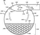
参考图2,示出了现有技术的泛滥式蒸发器80的示意图。该泛滥式蒸发器80包括基本圆柱形的蒸发器壳体114,该蒸发器壳体114具有顶部或上部146以及底部或下部148,所述底部或下部148具有形成热交换器管束132的多个管133。合适的流体(例如,水、乙烯、乙二醇或氯化钙液)流过管束132的管133。管束132在该泛滥式蒸发器80的整个长度上延伸(run),并且被液体制冷剂158覆盖或局部覆盖。抽吸隔板150在该泛滥式蒸发器80的整个长度上延伸,并且位于管束132上方以及所述泛滥式蒸发器80的上部146的下方。抽吸隔板150贴近于蒸发器壳体114,这在抽吸隔板150和蒸发器壳体114之间产生空间160。抽吸管115被附接至所述泛滥式蒸发器80的蒸发器壳体114的上部146。抽吸管115被附接至蒸发器壳体114,并且置于所述抽吸隔板150上方以及微滴脱离区域130上方,以减少携带进入压缩机60的液体。抽吸隔板150和蒸发器壳体114之间的空间160提供了一个区域,以允许蒸气制冷剂140从微滴脱离区域130流入抽吸渠道154中,然后进入将蒸气制冷剂140递送至压缩机60的抽吸管115中,以完成所述循环。应理解,所使用的术语“微滴脱离区域”的特征在于,在管束132和抽吸隔板150之间的区域,用于使制冷剂微滴与蒸气流分开。Referring to FIG. 2 , a schematic diagram of a prior art flooded
参考图3,根据一个示例实施方案示出了一个紧凑型泛滥式蒸发器180的示意图。泛滥式蒸发器180包括:抽吸隔板系统116;蒸发器壳体114;以及,在管束132中形成的多个热交换器管或多个管133。所述管束132在泛滥式蒸发器180的长度上延伸,并且局部或完全地被制冷剂158覆盖。抽吸隔板系统116包括一个抽吸隔板150和一个通道120。所述抽吸隔板150基本在泛滥式蒸发器180的长度上延伸,并且置于管束132上方以及泛滥式蒸发器180的上部146的下方。抽吸隔板150贴近于蒸发器壳体114,并且包括形成用于蒸气制冷剂140的空间160的多个槽118(参看图8)。通道120贴近于抽吸隔板150,或者从抽吸隔板150突出。在另一实施方案中,可通过一种合适的方法(例如,焊接或其他接合方法)将通道120附接至抽吸隔板150。在又一实施方案中,通道120可与抽吸隔板150整体成型为一个连续件。在又一实施方案中,抽吸隔板150和通道120可由单个基底整体成型,所述基底例如但是不限于碳钢或其他不锈(non-corroding)材料。通道120被配置为:当入口111被附接至蒸发器壳体114的外壁157时,其大体围绕地接收或包围抽吸管113的入口111的至少一部分。应理解,抽吸管113的入口111被附接至蒸发器壳体114的外部,并且通常不插入蒸发器壳体114的内部平面。通道120邻近于蒸发器壳体114的内壁156,并且通常不插入蒸发器壳体114的外部平面。在一个实施方案中,通道120包括一个底部表面142和至少两个通道侧壁144。如图3中所示,通道120的底部表面142从抽吸隔板150向下延伸,进入微滴脱离区域130,允许抽吸管113的入口111位于微滴脱离区域130中。通道侧壁144在朝向蒸发器壳体114的上部146和隔板150的方向上从底部表面142延伸,以限定通道120。通道侧壁144的尺寸被设置为允许附接至蒸发器壳体114的抽吸管113的入口111被定位在通道侧壁144和底部表面142之间。通道120的底部表面142和通道侧壁144被放在与蒸发器壳体114的内壁156处于极为贴近或邻接的关系中。抽吸隔板150和通道120的布置要求制冷剂在朝向抽吸管113的入口111的曲折路径中行进,使得在进入抽吸管113的入口111之前,被夹带在蒸气制冷剂140中的液体微滴与蒸发器壳体114的内壁156、抽吸隔板150或通道120碰撞。Referring to FIG. 3 , a schematic diagram of a compact flooded
如图3中进一步示出的,通道120阻止了微滴脱离区域130中的蒸气制冷剂140直接流入抽吸管113的入口111。通道120迫使蒸气制冷剂140流经抽吸渠道154,以减少携带的液体进入抽吸管113的入口111中。此外,通道120允许抽吸管113被切向或水平地附接至泛滥式蒸发器180,这减小了蒸发器高度,从而提供一个紧凑型泛滥式蒸发器180。应理解,术语“切向”被用于表征抽吸管113和蒸发器壳体114之间的取向,并且不要求抽吸管113和蒸发器壳体114的相应部分一致,例如图6中所示。换句话说,抽吸管线113和入口111可被定位为相对于蒸发器壳体114为非竖直取向,不与蒸发器壳体114的中心对准。在一个实施方案中,非竖直取向可被布置为使得抽吸管113的入口111和蒸发器壳体114之间的连接竖直地低于抽吸管113的相对端。As further shown in FIG. 3 ,
参考图4A和图4B,示出了根据另一示例实施方案的一种紧凑型降膜蒸发器280。该紧凑型降膜蒸发器280包括一个基本圆柱形蒸发器壳体114,该蒸发器壳体114具有上部146和下部148,所述下部具有形成管束132的多个管133沿着蒸发器壳体114的长度基本上水平延伸。一种合适的流体(例如,水、乙烯、乙二醇或氯化钙液)流过管束132的管133。放置在管束132上方的制冷剂分布器134将接收自冷凝器70的制冷剂138(例如,R134a)分布至管束132的上部管,所述制冷剂138处于液体状态或两相的液体和蒸气状态。换句话说,制冷剂流体138可以是两相状态,即液体和蒸气制冷剂。主要通过重力在管束132的管133之间所引导的且未改变为蒸气状态的液体制冷剂138在邻近于蒸发器280的下部148聚集,所述聚集的液体制冷剂被标示为液体制冷剂158。Referring to FIGS. 4A and 4B , a compact falling
再次参考图4B,罩124被定位盖在管束132上,基本上横向围绕管束132的基本所有管133,以基本上阻止管束132的管133之间的蒸气制冷剂140的交叉流动或液体和蒸气制冷剂的交叉流动。罩124包括上端或封闭端129,该上端或封闭端129在管束132上方和制冷剂分布器134上方邻近于蒸发器壳体114的上部146。在另一实施方案中,分布器134可被包括在罩124中。在又一实施方案中,分布器134的部分可在罩124的外部,只要基本上阻止了从分布器134初始分散并邻近于分布器134的制冷剂流过罩124。罩124从封闭端129的相对端朝向蒸发器壳体114的下部148延伸,并且包括多个相对的基本平行的壁125。在一个实施方案中,罩124的壁125在轮廓上既非平行的也非平面的。罩124的壁125朝向开口端127延伸且终止于开口端127处,所述开口端127基本上与罩124的封闭端129相对。优选地,封闭端129和壁125被放置为极为邻近于管束132的管133,且壁125朝向蒸发器壳体114的下部148充分延伸,以致基本上横向围绕管束132的管133。然而,不要求壁125竖直延伸超过管束132的下部管,也不要求壁125是平面的,尽管在管束132的轮廓线内形成的蒸气制冷剂140在壁125的约束中被基本上竖直引导,并穿过罩124的开口端127。罩124迫使壁125之间的蒸气制冷剂140朝下,并且穿过开口端127,然后在蒸发器壳体114和壁125之间的空间或微滴脱离区域130中从蒸发器壳体114的下部148朝上至蒸发器壳体114的上部146。然后蒸气制冷剂140流过邻近于蒸发器壳体114的上部146突出的隔板系统116,并且进入抽吸渠道154。蒸气制冷剂140通过多个槽118进入抽吸渠道154,所述多个槽118是隔板150的端部和蒸发器壳体114的内壁156之间的多个空间。在蒸气制冷剂140通过槽118进入抽吸渠道154之后,蒸气制冷剂140流过抽吸隔板系统116。抽吸隔板系统116包括一个抽吸隔板150和一个通道120。Referring again to FIG. 4B ,
如图4A中所示,通道120的底部表面142从抽吸隔板150朝下延伸进入微滴脱离区域130,从而允许抽吸管113的入口111置于微滴脱离区域130中。通道侧壁144在朝向蒸发器壳体114的上部146和抽吸隔板150的方向上从底部表面142延伸,以限定通道120。通道侧壁144的尺寸被设置为允许附接至蒸发器壳体114的抽吸管113的入口111被定位在通道侧壁144和底部表面142之间。通道120的底部表面142和通道侧壁144被放置为处于与蒸发器壳体114的内壁156极为贴近或邻接关系。As shown in FIG. 4A ,
如图4B中所示,通道120邻近于罩124的壁125,并且邻近于隔板150的隔板壁152。通道120包括一个底部表面142、多个通道侧壁144和一个连接器壁143。连接器壁143邻接罩124的壁125,且连接器壁143从壁125朝下延伸进入微滴脱离区域130至底部表面142。通道120的底部表面142从连接器壁143朝下延伸,进入微滴脱离区域130,允许抽吸管113的入口111位于微滴脱离区域130中。通道侧壁144在朝向蒸发器壳体146的内壁156的方向上从连接器壁143朝外延伸。通道侧壁144还在朝向蒸发器壳体114的上部146和抽吸隔板150的方向上从底部表面142延伸,以限定通道120。通道侧壁144的尺寸被设置为允许附接至蒸发器壳体114的抽吸管113的入口111定位在通道侧壁144和底部表面142之间。通道120的底部表面142、连接器壁143和通道侧壁144处于与蒸发器壳体114的内壁极为接近或邻接关系。As shown in FIG. 4B ,
在图4A和图4B中,抽吸隔板150和通道120的布置要求制冷剂在朝向抽吸管113的入口111的曲折路径上行进,使得在进入抽吸管113的入口111之前,夹带在蒸气制冷剂140中的液体微滴与蒸发器壳体114的内壁156、抽吸隔板150或通道120碰撞。在一个实施方案中,通道120邻接罩的壁125,并且被定位在隔板150的下方。在一个实施方案中,通道120可被焊接至壁125和抽吸隔板150。在另一实施方案中,通道120与壁125和抽吸隔板150整体形成。在又一实施方案中,通道120、壁125和抽吸隔板150可由单个连续材料形成。在图4A和图4B中,蒸气制冷剂140流经抽吸隔板150且进入通道120,之后在连接至压缩机60的抽吸管113的入口111处离开蒸发器280。In FIGS. 4A and 4B , the arrangement of the
参考图5-图8,示出了根据另一示例实施方案的紧凑型混合降膜蒸发器380。该紧凑型混合降膜蒸发器380包括:蒸发器壳体114;与上管束174流体连通的下管束172;罩124;制冷剂分布器134;抽吸隔板系统116;以及切向地附接至所述蒸发器壳体114的抽吸管113的入口111。蒸发器壳体114包括:上部146;下部148;内壁156;以及,外壁157。下管束172和上管束174各自具有在蒸发器壳体114中基本上水平延伸的多个管133。下管束172被蒸发器壳体114的下部148中的液体制冷剂158至少部分浸没。罩124被定位盖在上管束174上,并且包括一个封闭端129以及一个与所述封闭端129相对的开口端127。所述罩124的封闭端129在所述上管束174上方邻近于蒸发器壳体114的上部146。罩124还包括从封闭端129朝向邻近于蒸发器壳体114的下部148的开口端127延伸的多个相对壁125。制冷剂分布器134被定位在上管束174上方,并且通过多个喷嘴136将制冷剂分配至上管束174。抽吸隔板系统116被定位在蒸发器壳体114的上部146和上管束174之间,且抽吸隔板系统116位于罩124附近。抽吸隔板系统116包括一个抽吸隔板150和一个通道120。抽吸隔板150邻近于罩124,并且包括多个抽吸隔板壁152,所述抽吸隔板壁152具有在其中形成的多个槽118。抽吸隔板壁152从罩124的斜壁128延伸。通道120在至少一个抽吸隔板壁152下方朝向蒸发器壳体的下部148延伸,并且邻近于蒸发器壳体114的内壁156。通道120延伸进入微滴脱离区域130,并且适于接收抽吸管113的入口111的一部分。Referring to FIGS. 5-8 , a compact mixed falling
参考图5,示出的紧凑型混合降膜蒸发器380具有通道120,该通道120适于接收抽吸管113的入口111的一部分。入口111通常不突出进入或者穿过蒸发器壳体114的内壁156;然而,入口111被附接至蒸发器壳体的外壁157。通道120贴近于或邻接蒸发器壳体114的内壁156。尽管蒸发器壳体114将通道120与抽吸管道113的入口111物理地分隔开,但是通道120接收入口111的附接至蒸发器壳体114的外壁157的部分。Referring to FIG. 5 , a compact mixed falling
图6示出了沿线6-6所取的图5的横截面。示出了紧凑型蒸发器380的罩124和抽吸隔板系统116。抽吸隔板系统116包括具有多个抽吸槽118的抽吸隔板150以及通道120。通道120由碳钢或任何其他合适的材料构成。通道120包括一个底部表面142和多个通道侧壁144。在另一实施方案中,通道120还包括连接器壁143(参看图4B)。通道120的底部表面142在附接至蒸发器壳体114的抽吸管113的开口或入口111下方延伸。通道侧壁144在朝向蒸发器壳体114的上部146的方向上从通道120的底部表面142延伸,并且接触至少一个所述抽吸隔板壁152。通道侧壁144的尺寸被设置为允许抽吸管133的开口或入口111被定位其间。底部表面142和通道侧壁144被放置为处于与蒸发器壳体114的内壁156极为贴近或邻接关系,以阻止来自抽吸管113的吸力将蒸气制冷剂140流动流中的夹带液体直接从微滴脱离区域130或抽吸隔板150下方的区域抽到入口111中。Fig. 6 shows a cross-section of Fig. 5 taken along line 6-6. The
如图6和图7中所示,蒸发器入口122延伸穿过该紧凑型蒸发器壳体114的顶部并且穿过罩124,以将制冷剂递送至分布器134。在另一实施方案中,蒸发器入口122可延伸穿过蒸发器壳体114的其他部分。罩124被布置盖在所述上管束174上。所述罩124包括:中心部分126,其基本上在所述罩124的长度上延伸;以及,斜壁128,其从中心部分126的任一侧延伸。斜壁128进一步包括从斜壁128朝向蒸发器壳体114的下部148延伸的多个相对壁125。在一个实施方案中,相对壁125基本上是平面的,并且彼此平行。罩124的中心部分126、斜壁128和壁125在蒸发器壳体114的上部146附近形成封闭端129,以及在蒸发器壳体114的下部148附近形成开口端127。As shown in FIGS. 6 and 7 , the
参考图6和图7,抽吸隔板系统116被定位在蒸发器壳体114的上部146和上管束174的上方之间,并且抽吸隔板系统116邻近于罩124的多个斜壁128。抽吸隔板系统116包括一个抽吸隔板150、多个抽吸隔板壁152、多个槽118和一个通道120。抽吸隔板150包括多个槽118,所述槽118被抽吸隔板壁152的端部和蒸发器壳体114的内壁156之间的间隔限定。抽吸隔板壁152从罩124的斜壁128延伸,以形成一个抽吸渠道154。抽吸渠道154阻止蒸气制冷剂140绕罩124以及穿过微滴脱离区域130到达通向压缩机60(参看图1)的抽吸管113的入口111的流动的直接路径。Referring to FIGS. 6 and 7 , the
参考图7-图8,更好地示出了紧凑型蒸发器380的罩124和抽吸隔板系统116。罩124和抽吸隔板系统116基本上从该紧凑型蒸发器380的一个端部延伸至另一端部,并且基本上阻止了所施加的蒸气和雾形式的制冷剂流在上管束处直接流动进入抽吸管113的入口111。相反,通过将制冷剂引导为具有朝下方向的流动,蒸气制冷剂140必须向下行进穿过罩124的壁125的长度,之后制冷剂可穿过蒸发器380的开口端127或者抽吸隔板150的槽118。罩124的壁125基本上阻止了微滴脱离区域130中已提取的蒸气制冷剂140的交叉流动与行进穿过上管束174的多个管133的液体和蒸气制冷剂140混合。即,在蒸气制冷剂在相对壁125之间被引导然后经过所述相对壁125之前,流过上管束174的蒸气制冷剂或者液体和蒸气制冷剂混合物仅能通过开口端127离开罩124。Referring to FIGS. 7-8 , the
在蒸气制冷剂140经过罩124的开口端127(包括在方向上的急剧改变)之后,蒸气制冷剂140被迫在微滴脱离区域130中在罩124的壁125的外部、蒸发器壳体114的内壁156和抽吸隔板壁152之间行进。所述在罩124的壁125的端部处的急剧的方向改变造成任何携带的制冷剂微滴的绝大部分与液体制冷剂或蒸发器壳体114或罩124碰撞,从该蒸气制冷剂流140移除那些微滴。此外,沿基本上斜的抽吸隔板壁152的长度行进的制冷剂雾结合为较大的滴,所述较大的滴更容易通过重力而被分离,或通过热交换器管束132上的热传递而被蒸发。由于滴的尺寸增大,由重力导致的液体分离的效率提高,允许蒸气制冷剂140流过蒸发器380的向上速度增加。After vapor refrigerant 140 passes through
如图7和图8所示,抽吸隔板150贴近于平行壁125的顶部并且延伸进入抽吸渠道154中,以阻止蒸气制冷剂140至抽吸管113的一个直接路径。抽吸隔板150(邻近于罩124的壁125的上部端部突出)包括多个槽118,所述槽118被抽吸隔板壁152的端部和蒸发器壳体114的内壁156之间的间隔限定。蒸气制冷剂140通过抽吸隔板150的多个槽118进入抽吸渠道154,之后通过基本上围绕连接至压缩机60的抽吸管113的入口111的通道120离开蒸发器380。换句话说,罩124和抽吸隔板系统116的布置基本上将所有液体从蒸气制冷剂中移除,之后蒸气制冷剂140到达抽吸管113的入口111,且液体部分被排至蒸发器壳体114的下部148。通道120被设置为贴近于抽吸管113的入口111,以阻止携带在蒸气制冷剂140流动流中的液体被抽入抽吸管113。通过定位罩124、抽吸隔板150和通道120,使得携带液体进入口111和抽吸管113内的可能性最小化。由于包括通道120,蒸气制冷剂140仍需要流过由罩124和抽吸隔板壁152所形成的抽吸渠道154,之后进入抽吸管113的入口111,这使得携带液体进压缩机60中的可能性最小化。As shown in FIGS. 7 and 8 , the
如图3-图8所示,与当前系统不同,附接至抽吸隔板150的通道120基本上阻止了在管束132的顶部处携带蒸气和雾形式的蒸气制冷剂140流直接流至抽吸管113的入口111,所述抽吸管113的入口111被供给至压缩机60。与现有系统不同,入口111被部分定位在抽吸隔板150下方,或者定位在抽吸隔板150下方,并且大体上在微滴脱离区域130中。此外,还与现有系统不同,由于入口111的定位,抽吸管113相对于蒸发器壳体114基本上水平或切向地定位。切向的抽吸管113形成了一个更紧凑的蒸发器180、280、380,并且允许在对蒸发器的总高度有约束的冷冻机中更容易且更廉价的安装。切向抽吸管113还减小了被要求将该紧凑的蒸发器180、280、380连接至压缩机60的管路和接管的长度。抽吸管113的切向布置还使得成本降低和性能提高,并且容易制造和安装。As shown in FIGS. 3-8 , unlike current systems, the
尽管参考优选实施方案描述了本发明,但是本领域普通技术人员应理解,在不背离本发明的范围的前提下,可做出许多改变,并且等价物可替代其中的元件。此外,在不背离本发明本质范围的前提下,可做出许多改型,从而将具体情况或材料适配于本发明的教导。因而,意图是,本发明不局限于用于执行本发明所预期的最佳模式所公开的具体实施方案,而是本发明将包括落在随附权利要求书的范围内的所有实施方案。While the invention has been described with reference to a preferred embodiment, it will be understood by those skilled in the art that various changes may be made and equivalents may be substituted for elements thereof without departing from the scope of the invention. In addition, many modifications may be made to adapt a particular situation or material to the teachings of the invention without departing from the essential scope thereof. Therefore, it is intended that the invention not be limited to the particular embodiment disclosed as the best mode contemplated for carrying out this invention, but that the invention will include all embodiments falling within the scope of the appended claims.
Claims (20)
Applications Claiming Priority (3)
| Application Number | Priority Date | Filing Date | Title |
|---|---|---|---|
| US22764009P | 2009-07-22 | 2009-07-22 | |
| US61/227,640 | 2009-07-22 | ||
| PCT/US2010/042617WO2011011421A2 (en) | 2009-07-22 | 2010-07-20 | Compact evaporator for chillers |
Publications (2)
| Publication Number | Publication Date |
|---|---|
| CN102472589Atrue CN102472589A (en) | 2012-05-23 |
| CN102472589B CN102472589B (en) | 2014-01-22 |
Family
ID=43479466
Family Applications (1)
| Application Number | Title | Priority Date | Filing Date |
|---|---|---|---|
| CN201080030046.8AActiveCN102472589B (en) | 2009-07-22 | 2010-07-20 | Compact evaporator for chillers |
Country Status (4)
| Country | Link |
|---|---|
| US (1) | US8944152B2 (en) |
| EP (1) | EP2457051A2 (en) |
| CN (1) | CN102472589B (en) |
| WO (1) | WO2011011421A2 (en) |
Cited By (18)
| Publication number | Priority date | Publication date | Assignee | Title |
|---|---|---|---|---|
| CN104406334A (en)* | 2014-11-13 | 2015-03-11 | 广东申菱空调设备有限公司 | Sprinkling falling film type evaporator and liquid level control method thereof |
| CN104567053A (en)* | 2013-10-24 | 2015-04-29 | 松下知识产权经营株式会社 | Refrigeration-cycle equipment |
| CN105509371A (en)* | 2014-09-23 | 2016-04-20 | 博世热力技术(山东)有限公司 | Integrated unit for water chilling unit and water chilling unit |
| CN105593625A (en)* | 2013-08-23 | 2016-05-18 | 大金应用美国股份有限公司 | Heat exchanger |
| CN106512454A (en)* | 2016-11-18 | 2017-03-22 | 重庆美的通用制冷设备有限公司 | Tube shell type falling-film evaporator and water chilling unit |
| CN106907950A (en)* | 2013-03-15 | 2017-06-30 | 特灵国际有限公司 | The side-mounted input channel of side-mounted refrigerant distributor and distributor in flooded evaporator |
| CN107726886A (en)* | 2017-10-12 | 2018-02-23 | 江苏万节能科技股份有限公司 | A kind of heat exchanger |
| CN108603718A (en)* | 2015-12-11 | 2018-09-28 | 可口可乐公司 | The system and method for phase-change material panel and filling unit for providing the cabinet for cooling down vending machine |
| CN108709339A (en)* | 2018-07-02 | 2018-10-26 | 珠海格力电器股份有限公司 | Liquid distributor, falling film evaporator and air conditioner |
| CN108779968A (en)* | 2016-03-07 | 2018-11-09 | 大金应用美国股份有限公司 | Heat exchanger |
| CN109357441A (en)* | 2018-12-14 | 2019-02-19 | 珠海格力电器股份有限公司 | Falling film evaporator and air conditioner |
| CN110662936A (en)* | 2017-05-22 | 2020-01-07 | 大金应用美国股份有限公司 | Heat exchanger |
| WO2020034937A1 (en)* | 2018-08-14 | 2020-02-20 | 约克(无锡)空调冷冻设备有限公司 | Falling film evaporator |
| CN113195997A (en)* | 2018-12-19 | 2021-07-30 | 大金应用美国股份有限公司 | heat exchanger |
| CN113227698A (en)* | 2018-12-19 | 2021-08-06 | 大金应用美国股份有限公司 | Heat exchanger |
| CN113994165A (en)* | 2019-05-31 | 2022-01-28 | 鲁姆斯科技有限责任公司 | Spiral baffle heat exchanger |
| CN114076424A (en)* | 2020-08-14 | 2022-02-22 | 约克(无锡)空调冷冻设备有限公司 | Evaporator and refrigeration system |
| CN114076425A (en)* | 2020-08-14 | 2022-02-22 | 约克(无锡)空调冷冻设备有限公司 | Evaporator and refrigerating system |
Families Citing this family (38)
| Publication number | Priority date | Publication date | Assignee | Title |
|---|---|---|---|---|
| DE102007044658B3 (en)* | 2007-09-18 | 2008-12-04 | Gea Energietechnik Gmbh | Air-cooled dry radiator for condensing turbine steam, has suction chamber with troughs into which condensate enters and collected to be discharged into heat exchanger pipe over gas barrier in siphon form |
| EP2232167A1 (en)* | 2008-01-11 | 2010-09-29 | Johnson Controls Technology Company | Heat exchanger |
| EP2769161A4 (en)* | 2011-09-26 | 2015-08-05 | Ingersoll Rand Co | REFRIGERANT EVAPORATOR |
| EP2780650B1 (en) | 2011-11-18 | 2019-01-23 | Carrier Corporation | Shell and tube heat exchanger |
| WO2013112818A1 (en)* | 2012-01-27 | 2013-08-01 | Carrier Corporation | Evaporator and liquid distributor |
| US9541314B2 (en)* | 2012-04-23 | 2017-01-10 | Daikin Applied Americas Inc. | Heat exchanger |
| US9915452B2 (en)* | 2013-04-23 | 2018-03-13 | Carrier Corporation | Support sheet arrangement for falling film evaporator |
| US20160108762A1 (en)* | 2013-05-01 | 2016-04-21 | United Technologies Corporation | Falling film evaporator for power generation systems |
| EP3008299B1 (en)* | 2013-05-01 | 2020-05-13 | Nanjing TICA Thermal Technology Co., Ltd. | Falling film evaporator for mixed refrigerants |
| CN103727707A (en)* | 2013-12-30 | 2014-04-16 | 麦克维尔空调制冷(武汉)有限公司 | Full-falling-film evaporator with double refrigerant distribution devices |
| JP2016014495A (en)* | 2014-07-01 | 2016-01-28 | ダイキン工業株式会社 | Flowing film evaporator |
| FR3038037B1 (en)* | 2015-06-29 | 2018-04-20 | Trane International Inc. | SUCTION DUCT AND DUAL SUCTION DUCT FOR AN IMMERSION EVAPORATOR |
| CN104457040B (en)* | 2014-11-13 | 2017-09-22 | 广东申菱环境系统股份有限公司 | One kind spray downward film evaporator and its liquid level controlling method |
| WO2016102046A1 (en)* | 2014-12-23 | 2016-06-30 | Linde Aktiengesellschaft | Conducting device for controlling the flow of liquid when feeding two-phase flows in block-in-shell heat exchangers |
| FR3042858B1 (en)* | 2015-10-21 | 2018-01-12 | Technip France | THERMAL EXCHANGE DEVICE BETWEEN A FIRST FLUID FOR SPRAYING AND A SECOND FLUID FOR COOLING AND / OR CONDENSING, INSTALLATION AND METHOD THEREOF |
| US20170191718A1 (en)* | 2016-01-06 | 2017-07-06 | Johnson Controls Technology Company | Vapor compression system |
| WO2018039532A1 (en) | 2016-08-26 | 2018-03-01 | Carrier Corporation | Refrigerant distributor for falling film evaporator |
| CN106642845A (en)* | 2016-11-16 | 2017-05-10 | 珠海格力电器股份有限公司 | Refrigerating device, evaporator and liquid baffle plate thereof |
| EP3555542A4 (en)* | 2016-12-13 | 2020-12-02 | The Texas A&M University System | SENSITIVE AND LATENTARY HEAT EXCHANGERS WITH SPECIAL APPLICATION FOR STEAM COMPRESSION DESALINATION |
| CN108662812B (en) | 2017-03-31 | 2022-02-18 | 开利公司 | Flow balancer and evaporator having the same |
| JP6944337B2 (en)* | 2017-10-17 | 2021-10-06 | 三菱重工サーマルシステムズ株式会社 | Evaporator and freezing system |
| CN208332761U (en) | 2018-01-16 | 2019-01-04 | 开利公司 | Deflector for condenser, the condenser with it and refrigeration system |
| EP4350254A1 (en) | 2018-04-06 | 2024-04-10 | Carrier Corporation | Integrated separator and distributor |
| EP3640575B1 (en)* | 2018-10-15 | 2022-12-07 | Wieland Provides S.r.l. | Vertical heat exchanger |
| US11029094B2 (en)* | 2018-12-19 | 2021-06-08 | Daikin Applied Americas Inc. | Heat exchanger |
| EP3748272B1 (en)* | 2019-06-05 | 2022-08-17 | Mitsubishi Electric Hydronics & IT Cooling Systems S.p.A. | A hybrid tube bundle evaporator |
| EP3748270B1 (en)* | 2019-06-05 | 2022-08-17 | Mitsubishi Electric Hydronics & IT Cooling Systems S.p.A. | Hybrid tube bundle evaporator |
| FR3097307B1 (en)* | 2019-06-17 | 2021-05-14 | Naval Energies | Evaporator of a working fluid for an ETM plant comprising a cover |
| FR3097308B1 (en)* | 2019-06-17 | 2021-11-05 | Naval Energies | Evaporator of a working fluid for an ETM plant comprising a suitable sprinkler system |
| ES2957327T3 (en) | 2019-12-03 | 2024-01-17 | Carrier Corp | Flooded evaporator |
| KR102292397B1 (en) | 2020-02-13 | 2021-08-20 | 엘지전자 주식회사 | Evaporator |
| KR102292395B1 (en)* | 2020-02-13 | 2021-08-20 | 엘지전자 주식회사 | Evaporator |
| KR102292396B1 (en) | 2020-02-13 | 2021-08-20 | 엘지전자 주식회사 | Evaporator |
| JP7098680B2 (en)* | 2020-04-03 | 2022-07-11 | 三菱重工サーマルシステムズ株式会社 | Evaporator |
| JP6880277B1 (en) | 2020-04-08 | 2021-06-02 | 三菱重工サーマルシステムズ株式会社 | Evaporator |
| CN113513931B (en)* | 2020-04-09 | 2025-09-09 | 开利公司 | Heat exchanger |
| US12066224B2 (en)* | 2022-06-03 | 2024-08-20 | Trane International Inc. | Evaporator charge management and method for controlling the same |
| WO2025024250A1 (en)* | 2023-07-21 | 2025-01-30 | Trane International Inc. | Evaporator with liquid phase distribution |
Citations (5)
| Publication number | Priority date | Publication date | Assignee | Title |
|---|---|---|---|---|
| US2012183A (en)* | 1934-03-09 | 1935-08-20 | Carrier Engineering Corp | Shell and tube evaporator |
| CN1409810A (en)* | 1999-12-17 | 2003-04-09 | 美国标准公司 | Falling film evaporator for vapor compression refrigeration chiller |
| US6868695B1 (en)* | 2004-04-13 | 2005-03-22 | American Standard International Inc. | Flow distributor and baffle system for a falling film evaporator |
| CN101052854A (en)* | 2004-10-13 | 2007-10-10 | 约克国际公司 | Falling film evaporator |
| US20080148767A1 (en)* | 2006-12-21 | 2008-06-26 | Johnson Controls Technology Company | Falling film evaporator |
Family Cites Families (19)
| Publication number | Priority date | Publication date | Assignee | Title |
|---|---|---|---|---|
| US2059725A (en)* | 1934-03-09 | 1936-11-03 | Carrier Engineering Corp | Shell and tube evaporator |
| US2354497A (en)* | 1943-06-12 | 1944-07-25 | Robert T Brizzolara | Refrigeration apparatus |
| US2453662A (en)* | 1944-03-02 | 1948-11-09 | Graham Mfg Co Inc | Condenser |
| US2504710A (en)* | 1947-08-18 | 1950-04-18 | Westinghouse Electric Corp | Evaporator apparatus |
| US2986377A (en)* | 1956-04-17 | 1961-05-30 | Ingersoll Rand Co | Condenser |
| US3240265A (en)* | 1962-10-03 | 1966-03-15 | American Radiator & Standard | Refrigeration evaporator system of the flooded type |
| US3141311A (en)* | 1963-01-14 | 1964-07-21 | Carrier Corp | Refrigeration system and apparatus for operating at partial loads |
| US3197387A (en)* | 1963-05-20 | 1965-07-27 | Baldwin Lima Hamilton Corp | Multi-stage flash evaporators |
| US3267693A (en)* | 1965-06-29 | 1966-08-23 | Westinghouse Electric Corp | Shell-and-tube type liquid chillers |
| US3412569A (en)* | 1966-02-21 | 1968-11-26 | Carrier Corp | Refrigeration apparatus |
| DE1751489A1 (en)* | 1968-06-07 | 1971-07-08 | Aluminium U Metallwarenfabrik | Heat exchanger for the liquefaction or evaporation of refrigerants |
| US5246541A (en)* | 1991-05-14 | 1993-09-21 | A. Ahlstrom Corporation | Evaporator for liquid solutions |
| JP3368326B2 (en)* | 1994-04-04 | 2003-01-20 | 日揮株式会社 | Heat exchange device and multi-stage heat exchange device |
| US5588596A (en)* | 1995-05-25 | 1996-12-31 | American Standard Inc. | Falling film evaporator with refrigerant distribution system |
| US6516627B2 (en)* | 2001-05-04 | 2003-02-11 | American Standard International Inc. | Flowing pool shell and tube evaporator |
| KR101327679B1 (en)* | 2005-03-21 | 2013-11-08 | 비피 코포레이션 노쓰 아메리카 인코포레이티드 | Process and apparatus for manufacturing pure forms of aromatic carboxylic acids |
| TWI320094B (en)* | 2006-12-21 | 2010-02-01 | Spray type heat exchang device | |
| US7707850B2 (en)* | 2007-06-07 | 2010-05-04 | Johnson Controls Technology Company | Drainage mechanism for a flooded evaporator |
| US20090165497A1 (en)* | 2007-12-31 | 2009-07-02 | Johnson Controls Technology Company | Heat exchanger |
- 2010
- 2010-07-20USUS12/839,658patent/US8944152B2/enactiveActive
- 2010-07-20WOPCT/US2010/042617patent/WO2011011421A2/enactiveApplication Filing
- 2010-07-20EPEP10737197Apatent/EP2457051A2/ennot_activeWithdrawn
- 2010-07-20CNCN201080030046.8Apatent/CN102472589B/enactiveActive
Patent Citations (5)
| Publication number | Priority date | Publication date | Assignee | Title |
|---|---|---|---|---|
| US2012183A (en)* | 1934-03-09 | 1935-08-20 | Carrier Engineering Corp | Shell and tube evaporator |
| CN1409810A (en)* | 1999-12-17 | 2003-04-09 | 美国标准公司 | Falling film evaporator for vapor compression refrigeration chiller |
| US6868695B1 (en)* | 2004-04-13 | 2005-03-22 | American Standard International Inc. | Flow distributor and baffle system for a falling film evaporator |
| CN101052854A (en)* | 2004-10-13 | 2007-10-10 | 约克国际公司 | Falling film evaporator |
| US20080148767A1 (en)* | 2006-12-21 | 2008-06-26 | Johnson Controls Technology Company | Falling film evaporator |
Cited By (29)
| Publication number | Priority date | Publication date | Assignee | Title |
|---|---|---|---|---|
| US10914525B2 (en) | 2013-03-15 | 2021-02-09 | Trane International Inc. | Side mounted refrigerant distributor in a flooded evaporator and side mounted inlet pipe to the distributor |
| CN106907950A (en)* | 2013-03-15 | 2017-06-30 | 特灵国际有限公司 | The side-mounted input channel of side-mounted refrigerant distributor and distributor in flooded evaporator |
| CN106907950B (en)* | 2013-03-15 | 2019-06-21 | 特灵国际有限公司 | The side-mounted input channel of side-mounted refrigerant distributor and distributor in flooded evaporator |
| US10126066B2 (en) | 2013-03-15 | 2018-11-13 | Trane International Inc. | Side mounted refrigerant distributor in a flooded evaporator and side mounted inlet pipe to the distributor |
| CN105593625A (en)* | 2013-08-23 | 2016-05-18 | 大金应用美国股份有限公司 | Heat exchanger |
| CN104567053A (en)* | 2013-10-24 | 2015-04-29 | 松下知识产权经营株式会社 | Refrigeration-cycle equipment |
| CN105509371A (en)* | 2014-09-23 | 2016-04-20 | 博世热力技术(山东)有限公司 | Integrated unit for water chilling unit and water chilling unit |
| CN104406334B (en)* | 2014-11-13 | 2017-08-11 | 广东申菱环境系统股份有限公司 | One kind spray downward film evaporator and its liquid level controlling method |
| CN104406334A (en)* | 2014-11-13 | 2015-03-11 | 广东申菱空调设备有限公司 | Sprinkling falling film type evaporator and liquid level control method thereof |
| CN108603718A (en)* | 2015-12-11 | 2018-09-28 | 可口可乐公司 | The system and method for phase-change material panel and filling unit for providing the cabinet for cooling down vending machine |
| CN108779968B (en)* | 2016-03-07 | 2021-03-12 | 大金应用美国股份有限公司 | heat exchanger |
| CN108779968A (en)* | 2016-03-07 | 2018-11-09 | 大金应用美国股份有限公司 | Heat exchanger |
| CN106512454A (en)* | 2016-11-18 | 2017-03-22 | 重庆美的通用制冷设备有限公司 | Tube shell type falling-film evaporator and water chilling unit |
| CN106512454B (en)* | 2016-11-18 | 2018-11-23 | 重庆美的通用制冷设备有限公司 | A kind of shell-and-tube type falling film evaporator and water cooler |
| CN110662936B (en)* | 2017-05-22 | 2021-06-01 | 大金应用美国股份有限公司 | Heat exchanger |
| CN110662936A (en)* | 2017-05-22 | 2020-01-07 | 大金应用美国股份有限公司 | Heat exchanger |
| CN107726886A (en)* | 2017-10-12 | 2018-02-23 | 江苏万节能科技股份有限公司 | A kind of heat exchanger |
| CN108709339A (en)* | 2018-07-02 | 2018-10-26 | 珠海格力电器股份有限公司 | Liquid distributor, falling film evaporator and air conditioner |
| WO2020034937A1 (en)* | 2018-08-14 | 2020-02-20 | 约克(无锡)空调冷冻设备有限公司 | Falling film evaporator |
| US11644223B2 (en) | 2018-08-14 | 2023-05-09 | Johnson Controls Tyco IP Holdings LLP | Falling film evaporator |
| CN109357441A (en)* | 2018-12-14 | 2019-02-19 | 珠海格力电器股份有限公司 | Falling film evaporator and air conditioner |
| CN109357441B (en)* | 2018-12-14 | 2024-05-03 | 珠海格力电器股份有限公司 | Falling film evaporator and air conditioner |
| CN113195997A (en)* | 2018-12-19 | 2021-07-30 | 大金应用美国股份有限公司 | heat exchanger |
| CN113227698A (en)* | 2018-12-19 | 2021-08-06 | 大金应用美国股份有限公司 | Heat exchanger |
| CN113227698B (en)* | 2018-12-19 | 2023-07-14 | 大金工业株式会社 | heat exchanger |
| CN113195997B (en)* | 2018-12-19 | 2023-08-01 | 大金工业株式会社 | heat exchanger |
| CN113994165A (en)* | 2019-05-31 | 2022-01-28 | 鲁姆斯科技有限责任公司 | Spiral baffle heat exchanger |
| CN114076424A (en)* | 2020-08-14 | 2022-02-22 | 约克(无锡)空调冷冻设备有限公司 | Evaporator and refrigeration system |
| CN114076425A (en)* | 2020-08-14 | 2022-02-22 | 约克(无锡)空调冷冻设备有限公司 | Evaporator and refrigerating system |
Also Published As
| Publication number | Publication date |
|---|---|
| US8944152B2 (en) | 2015-02-03 |
| US20110017432A1 (en) | 2011-01-27 |
| WO2011011421A2 (en) | 2011-01-27 |
| WO2011011421A3 (en) | 2011-03-31 |
| CN102472589B (en) | 2014-01-22 |
| EP2457051A2 (en) | 2012-05-30 |
Similar Documents
| Publication | Publication Date | Title |
|---|---|---|
| CN102472589B (en) | Compact evaporator for chillers | |
| CN102788451B (en) | Vapor compression system | |
| CN108779968B (en) | heat exchanger | |
| US10132537B1 (en) | Heat exchanger | |
| CN101052854B (en) | Falling film evaporator | |
| CN113227698B (en) | heat exchanger | |
| JP2005502016A (en) | Flowing pool shell and tubular evaporator | |
| US11029094B2 (en) | Heat exchanger | |
| US11959671B2 (en) | Refrigerant distributor and evaporator comprising the refrigerant distributor | |
| EP3842728B1 (en) | Heat exchanger and air conditioner | |
| US9903659B2 (en) | Low pressure chiller | |
| US20070107886A1 (en) | Evaporator for a refrigeration system | |
| KR101379214B1 (en) | Apparatus and method for separating droplets from vaporized refrigerant | |
| KR20140073124A (en) | Evaporator and Turbo chiller comprising the same | |
| KR890004394B1 (en) | Compressed Refrigerator with Gas-liquid Separator | |
| CN113195997B (en) | heat exchanger | |
| KR102047688B1 (en) | Evaporator and Turbo chiller comprising the same | |
| KR200303998Y1 (en) | Oil-separator of cooling unit |
Legal Events
| Date | Code | Title | Description |
|---|---|---|---|
| C06 | Publication | ||
| PB01 | Publication | ||
| C10 | Entry into substantive examination | ||
| SE01 | Entry into force of request for substantive examination | ||
| C14 | Grant of patent or utility model | ||
| GR01 | Patent grant | ||
| TR01 | Transfer of patent right | Effective date of registration:20230221 Address after:Wisconsin Patentee after:Johnson Controls Tyco intellectual property holdings limited liability partnership Address before:Michigan, USA Patentee before:JOHNSON CONTROLS TECHNOLOGY Co. | |
| TR01 | Transfer of patent right | ||
| TR01 | Transfer of patent right | Effective date of registration:20250205 Address after:Switzerland Rhine falls Neuhausen Patentee after:TYCO FIRE & SECURITY GmbH Country or region after:Switzerland Address before:Wisconsin Patentee before:Johnson Controls Tyco intellectual property holdings limited liability partnership Country or region before:U.S.A. | |
| TR01 | Transfer of patent right |