CN102465725A - The barring assembly that drives the shaft rotation of the turbo alternator set - Google Patents
The barring assembly that drives the shaft rotation of the turbo alternator setDownload PDFInfo
- Publication number
- CN102465725A CN102465725ACN201110103919XACN201110103919ACN102465725ACN 102465725 ACN102465725 ACN 102465725ACN 201110103919X ACN201110103919X ACN 201110103919XACN 201110103919 ACN201110103919 ACN 201110103919ACN 102465725 ACN102465725 ACN 102465725A
- Authority
- CN
- China
- Prior art keywords
- jiggering
- shaft
- module
- gear
- barring
- Prior art date
- Legal status (The legal status is an assumption and is not a legal conclusion. Google has not performed a legal analysis and makes no representation as to the accuracy of the status listed.)
- Granted
Links
Images

Classifications
- F—MECHANICAL ENGINEERING; LIGHTING; HEATING; WEAPONS; BLASTING
- F01—MACHINES OR ENGINES IN GENERAL; ENGINE PLANTS IN GENERAL; STEAM ENGINES
- F01D—NON-POSITIVE DISPLACEMENT MACHINES OR ENGINES, e.g. STEAM TURBINES
- F01D25/00—Component parts, details, or accessories, not provided for in, or of interest apart from, other groups
- F01D25/34—Turning or inching gear
- F01D25/36—Turning or inching gear using electric motors
- F—MECHANICAL ENGINEERING; LIGHTING; HEATING; WEAPONS; BLASTING
- F05—INDEXING SCHEMES RELATING TO ENGINES OR PUMPS IN VARIOUS SUBCLASSES OF CLASSES F01-F04
- F05D—INDEXING SCHEME FOR ASPECTS RELATING TO NON-POSITIVE-DISPLACEMENT MACHINES OR ENGINES, GAS-TURBINES OR JET-PROPULSION PLANTS
- F05D2220/00—Application
- F05D2220/30—Application in turbines
- F05D2220/31—Application in turbines in steam turbines
- F—MECHANICAL ENGINEERING; LIGHTING; HEATING; WEAPONS; BLASTING
- F05—INDEXING SCHEMES RELATING TO ENGINES OR PUMPS IN VARIOUS SUBCLASSES OF CLASSES F01-F04
- F05D—INDEXING SCHEME FOR ASPECTS RELATING TO NON-POSITIVE-DISPLACEMENT MACHINES OR ENGINES, GAS-TURBINES OR JET-PROPULSION PLANTS
- F05D2260/00—Function
- F05D2260/40—Transmission of power
- F05D2260/403—Transmission of power through the shape of the drive components
- F05D2260/4031—Transmission of power through the shape of the drive components as in toothed gearing
Landscapes
- Engineering & Computer Science (AREA)
- Mechanical Engineering (AREA)
- General Engineering & Computer Science (AREA)
- Gear Transmission (AREA)
- Connection Of Motors, Electrical Generators, Mechanical Devices, And The Like (AREA)
Abstract
Description
Translated fromChinese技术领域technical field
本发明涉及汽轮交流发电机组(汽轮交流发电机组)领域。其特别聚焦于蒸汽汽轮机,但可以应用于燃气汽轮机。这些汽轮机被在发电厂使用,每个汽轮机驱动发电机发电。这可以是操作化石型能源或非传统能源的工厂。The invention relates to the field of steam turbine alternator set (steam turbine alternator set). It is specifically focused on steam turbines, but can be applied to gas turbines. These turbines are used in power plants, each driving a generator to generate electricity. This can be a plant operating on fossil-based or non-conventional energy sources.
背景技术Background technique
更特别地,本发明涉及用于驱动包括每个汽轮机模块的转子以及发电机转子的轴进行旋转的盘车组件(barring gear assembly)。旋转借助于能够克服轴的阻抗性连接的辅助电机而发生。转动周期发生在汽轮交流发电机组发电周期之前或之后的阶段期间。根据均匀转子温度并且因此避免轴在热非对称的作用下发生任何弯曲,在汽轮交流发电机组的启动和停止周期期间必须使轴旋转。在蒸汽注射到汽轮机内之前的启动阶段期间盘车组件还启动轴的旋转。转动阶段期间轴的转速很低并且是恒定的。根据汽轮交流发电机组,该转速从每分钟几转到每分钟几十转变化。More particularly, the present invention relates to a barring gear assembly for driving in rotation a shaft including the rotor of each steam turbine module and the generator rotor. The rotation takes place by means of an auxiliary motor capable of overcoming the resistive connection of the shaft. A turning cycle occurs during a phase preceding or following a turbo-alternator generating cycle. It is necessary to rotate the shaft during the start and stop cycles of the turbo-alternator unit in terms of uniform rotor temperature and thus avoiding any bending of the shaft under the effect of thermal asymmetry. The barring assembly also initiates shaft rotation during the start-up phase prior to steam injection into the turbine. The rotational speed of the shaft is low and constant during the turning phase. Depending on the turbo-alternator unit, this rotational speed varies from several to tens of revolutions per minute.
根据现有技术的盘车组件,转动功能通过借助于液压联接器驱动第一齿轮的电机执行。此初始减小通过安装在轴电机上的小齿轮和固定在第二轴上的被引导齿轮而实现。第二轴通过第二齿轮连接到轴上,在第二齿轮处一个齿轮被固定在离合器上。离合器从轴上断开盘车组件。所有部件被容纳在箱体内,除电机和液压联接器外。这种布置具有许多缺点:According to prior art barring assemblies, the turning function is performed by an electric motor driving the first gear by means of a hydraulic coupling. This initial reduction is achieved by a pinion mounted on the shaft motor and a piloted gear fixed on the second shaft. The second shaft is connected to the shaft by a second gear where a gear is secured to the clutch. The clutch disconnects the barring assembly from the shaft. All components are housed in the box, except the motor and hydraulic coupling. This arrangement has a number of disadvantages:
-轴上的离合器的存在使得盘车组件的维修操作高度复杂。拆卸盘车组件需要拆卸此离合器和轴最近端之间的部件。这尤其意味着,在重新装配每个部件时要进行非常长时间和复杂的调整操作。特别地,轴上的离合器的存在不允许盘车组件放置在轴的两个电机之间。- The presence of the clutch on the shaft makes the maintenance operations of the barring assembly highly complicated. Removal of the barring assembly requires removal of components between this clutch and the nearest end of the shaft. This means, inter alia, very long and complicated adjustment operations when reassembling each component. In particular, the presence of the clutch on the shaft does not allow the barring assembly to be placed between the two motors of the shaft.
-被置于箱体内部的液压联接器和蜗杆之间的挠性联接遭遇油喷射和油蒸发产生的空气。因此,严重缩短了其保质期限。- The flexible coupling between the hydraulic coupling and the worm, which is placed inside the case, encounters air from oil injection and oil evaporation. Therefore, its shelf life is seriously shortened.
-离合器的可触及性非常差,- the clutch is very poorly accessible,
-布置不是最佳的。轴上的离合器的存在必须使所述轴延长。因此增大了汽轮交流发电机组的总体积。- The layout is not optimal. The presence of the clutch on the shaft must lengthen the shaft. Therefore, the overall volume of the turbo-alternator unit is increased.
发明内容Contents of the invention
本发明的目的是通过改善可触及性而消除这些缺点,使维修容易,减小体积并且简化设备。The object of the present invention is to eliminate these disadvantages by improving accessibility, facilitating maintenance, reducing volume and simplifying equipment.
本发明涉及例如在权利要求中限定的盘车组件和汽轮交流发电机组。The invention relates to a barring assembly and a turbo-alternator unit such as those defined in the claims.
根据本发明的盘车组件被设计成用于驱动汽轮交流发电机组的具有旋转轴线(A)的轴旋转。所述盘车组件包括主齿轮,其被固定于所述轴上并且具有位于旋转轴线每侧的侧边,盘车模块,其具有支撑件,其所述支撑件上安装有离合器系统,用于将第二轴连接至所述主齿轮和从其上面脱开。所述第二轴通过辅助马达驱动。所述盘车模块被定位于所述旋转轴线的其中一个所述侧边上。这样简化了部件的布置结构并且组件更紧凑。特别地,减小了轴的轴向体积,其反过来减小了机械车间的轴向体积并且减小了汽轮交流发电机组的混凝土承重结构的尺寸。简化了盘车模块的干涉,因为不再需要干涉汽轮机轴,而是相对于汽轮机轴后退了。而且盘车模块可以在整个设备之外制备。而且,本发明可以将盘车组件放置在轴上的任何点处并且不必须放置于轴的端部:因此,主齿轮可以被置于两个汽轮机转子之间,并且盘车组件可以被置于该位置上。The barring assembly according to the invention is designed for driving in rotation a shaft of a turbo-alternator unit having an axis of rotation (A). The barring assembly includes a main gear fixed to the shaft and having sides on each side of the axis of rotation, a barring module having a support on which is mounted a clutch system for Connect and disconnect the secondary shaft to the main gear. The second shaft is driven by an auxiliary motor. The barring module is positioned on one of the sides of the axis of rotation. This simplifies the arrangement of components and makes the assembly more compact. In particular, the axial volume of the shaft is reduced, which in turn reduces the axial volume of the machine shop and reduces the size of the concrete load-bearing structure of the turbo-alternator unit. The interfering of the barring module is simplified, since it is no longer necessary to interfere with the turbine shaft, but instead it is set back relative to the turbine shaft. Furthermore, the barring module can be produced outside the entire plant. Furthermore, the invention allows the barring assembly to be placed at any point on the shaft and not necessarily at the end of the shaft: thus, the main gear can be placed between the two turbine rotors and the barring assembly can be placed at the end of the shaft. on the position.
根据另一方面,离合器系统被安装于比汽轮机的旋转轴线低的水平,这增强了盘车组件的支撑体的刚性和稳定性。优选地,第二轴位于分割线下面。支撑体因为比较低所以刚性好很多。According to another aspect, the clutch system is mounted at a lower level than the axis of rotation of the steam turbine, which enhances the rigidity and stability of the support body of the barring assembly. Preferably, the second axis is located below the dividing line. The support body is much more rigid because it is relatively low.
根据优选的特征,离合器系统安装在适于在所述支撑件上旋转的所述第二轴上。此特征在于能够实现具有良好稳定性的盘车装置的模块式结构。因此,在脱开的位置上,特别是在产能过程中,第二轴不转动。第二轴只在电机旋转时的转动阶段期间转动。According to a preferred feature, the clutch system is mounted on said second shaft adapted to rotate on said support. This is characterized by a modular structure enabling a barring device with good stability. Therefore, in the disengaged position, in particular during the production process, the second shaft does not rotate. The second shaft turns only during the turn phase when the motor turns.
根据另一特别优选的特征,离合器系统包括被安装成可沿所述第二轴移动的小齿轮,所述小齿轮的移动能够使所述电机通过所述第二轴连接至所述主齿轮和从其上面脱开。此特征在于使得更容易对离合器进行视觉控制。例如,在离合器上出现问题的情况下,很容易对离合器进行初始视觉控制。According to another particularly preferred feature, the clutch system comprises a pinion mounted displaceable along said second shaft, movement of said pinion enabling said motor to be connected via said second shaft to said main gear and detach from it. This feature allows for easier visual control of the clutch. For example, it is easy to have initial visual control of the clutch in the event of a problem on the clutch.
根据另一优选的特征,盘车模块包括驱动所述第二轴的齿轮减速器,所述齿轮减速器被安装于所述支撑件上。此特征在于给出了适当的减速比并且保持盘车的模块式结构。According to another preferred feature, the barring module comprises a gear reducer driving said second shaft, said gear reducer being mounted on said support. This feature is given the appropriate reduction ratio and maintains the modular structure of the barring.
根据另一优选的特征,齿轮减速器包括减速齿轮和蜗杆,所述齿轮被与所述离合器系统并肩地安装。这种结构实现了盘车的模块式结构。According to another preferred feature, the gear reducer comprises a reduction gear and a worm, said gear being mounted alongside said clutch system. This structure realizes the modular structure of the barring.
根据另一优选的特征,盘车模块被安装在所述箱体内并且所述蜗杆延长形成穿过所述箱体的轴。此特征在于将电机、液压联接器和挠性联接置于箱体外面。According to another preferred feature, the barring module is mounted in said box and said worm is extended to form a shaft passing through said box. This feature places the motor, hydraulic coupling and flexible coupling outside the box.
优选地,蜗杆轴经过可拆除的挡板穿过所述箱体。这将在箱体内连续地安装和移除盘车模块。Preferably, the worm shaft passes through the housing via a removable baffle. This will sequentially install and remove the barring modules within the box.
根据实施例,蜗杆轴具有位于箱体外面的端部,所述端部通过液压联接器和挠性联接连接至所述电机。箱体外面的挠性联接不再遭遇箱体内的腐蚀性空气。According to an embodiment, the worm shaft has an end located outside the housing, said end being connected to said motor by means of a hydraulic coupling and a flexible coupling. The flexible connection outside the box no longer encounters the corrosive air inside the box.
本发明还涉及用于发电的汽轮交流发电机组,包括至少一个汽轮机模块和被蒸汽驱动的轴,所述轴被构造成适于通过盘车组件驱动。The invention also relates to a turbo-alternator unit for generating electricity, comprising at least one steam turbine module and a steam-driven shaft configured to be driven by a barring assembly.
附图说明Description of drawings
从下面通过示例并且参照附图给出的描述中将更好地理解本发明,其中:The invention will be better understood from the following description given by way of example and with reference to the accompanying drawings, in which:
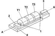
图1示意了根据本发明的发电汽轮交流发电机组的透视图;Figure 1 illustrates a perspective view of a power generating turbo-alternator unit according to the present invention;
图2示意了根据本发明的盘车组件从上面看的透视图;Figure 2 illustrates a perspective view from above of a barring assembly according to the invention;
图3示意了根据本发明的盘车组件从上面看的视图;Figure 3 illustrates a view from above of the barring assembly according to the invention;
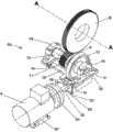
图4示意了根据本发明的盘车模块的视图。Figure 4 illustrates a view of the barring module according to the invention.
具体实施方式Detailed ways
图1示意了用于发电的汽轮交流发电机组,其包括驱动蒸汽发电机3的汽轮机模块的组件,在本实例中,是三个汽轮机模块T1、T2、T3。本汽轮交流发电机组位于通常由混凝土制成的刚性结构框架5上。在本实例中,发电的功率在500MW和2000MW之间。汽轮机模块的转子驱动发电机3绕轴线A旋转。发电机位于汽轮交流发电机组的后面。轴被延伸至前面,在发电机3相反的一端,直至盘车组件(barring gear assembly)2。借助于辅助马达4,盘车组件2通过离合器系统6驱动轴1旋转,离合器系统6连接轴1与马达4或断开轴1与马达4的连接。在发电过程中,汽轮机不与马达连接。马达4优选是电动机。根据本发明,盘车组件还可以被置于两个汽轮机模块(T1、T2、T3)之间或最后一个汽轮机模块(这里是T3)和发电机3之间。Figure 1 schematically illustrates a turbo-alternator plant for power generation comprising an assembly of steam turbine modules driving a
图2和3更精确地示意了盘车组件2。盘车模块10被安装在箱体7内,盖(图中未示意出)已经从箱体7上拆下以显示内部机构。此盖在此箱体的分割线36的水平被固定在箱体上。箱体7具有在轴的每一侧延伸出箱体的基部38。箱体7具有位于汽轮机的轴线A的任一侧的两个侧壁32、33,后壁34和前壁35。在操作中,箱体7被封闭并密封,通过盖封闭。箱体具有接收轴1的旋转端部的轴承8。轴承8抵靠着箱体的前壁35放置。主齿轮9固定在轴1上,这里固定在端部。由于本发明的特征,齿轮9可以具有优势地被固定在轴上不同于所述上述端部的位置:优选地,主齿轮9可以被设置于两个汽轮机模块之间或最后一个汽轮机模块和发电机之间。位于所述主齿轮9的外围侧的是盘车模块10。更确切地说,主齿轮9限定出位于旋转轴线A的任一侧上的侧边C1、C2,并且盘车模块10被定位于旋转轴线A的其中一个侧边上,这里是C1。2 and 3 illustrate the barring
盘车模块10包括离合器系统6,离合器系统6包括安装在第二轴12上的小齿轮11。小齿轮11可以沿所述第二轴12移动,但被相对于第二轴12旋转地连接到第二轴12上。图2和3示出了从主齿轮9上脱开的小齿轮11,并且然后盘车模块10从轴1上脱开。移动距离D将使小齿轮11啮合在主齿轮9上,然后盘车模块10被接合至汽轮机的轴1。主齿轮9和小齿轮11的齿是直齿,以使小齿轮很容易地接合在齿轮上。The barring
第二轴12被安装成在位于小齿轮11每一侧的两个上轴承13、14上旋转。这两个上轴承被安装在靠在箱体7的接收表面上的支撑件15上面。第二轴12可以设置成通过安装在支撑件15上的减速齿轮17和蜗杆18旋转。减速器的齿轮17布置于小齿轮11旁边和第二轴12的两个上轴承13、14之间。蜗杆18被置于齿轮17下面并且位于比第二轴12低的水平。安装成在第二轴上运动的小齿轮11构成离合器系统6。The
盘车组件2的减速比相对于关于现有技术描述的减小了:马达4以750rpm(以前是1500rpm)转动。这种马达转速的降低减小了与减速齿轮17和蜗杆18的减速比以及齿轮9和小齿轮11的减速比相对应的总减速比。The reduction ratio of the barring
通过液压联接器(hydraulic coupler)和液压联接器和蜗杆之间的挠性联接,蜗杆18延长形成连接到马达4上的轴20。通过支撑马达4的中间件37,马达被固定在箱体的底板21上。蜗杆的轴20穿过箱体的壁。为实现此目的,必须在侧壁32上制造开口。此开口从轴20通过的位置开始延伸直至箱体7的分割线36。此开口通过可拆除的挡板22封闭,这里通过箱体7的侧壁32上的螺栓固定。The
图3示出了由于将离合器系统6定位于主齿轮9一侧上侧挡板32和所述主齿轮之间而获得的组件的紧密性。第二轴12布置于汽轮机轴1的横向侧并且平行于汽轮机的轴1。这种紧密性可以进一步通过使离合器系统6位于比轴1低的水平上而得到增强。图2示出了第二轴12相对于汽轮机轴线A的相对位置。第二轴12布置于汽轮机轴线A横向侧并且位于其下面。盘车模块10优选布置于比箱体7的分割线低的水平。而且,轴20布置成垂直于汽轮机的轴1。FIG. 3 shows the compactness of the assembly obtained due to the positioning of the
将第二轴12放置在齿轮9的侧面获得了长度并且减小轴20的长度并且使对正错误引起的问题最少。而且,将第二轴12置于旋转轴线A下面获得了宽度。Placing the
将盘车模块10固定在箱体7内比旋转轴线A低的高度水平向取消了长的非刚性支撑脚而导致可能振动的设备提供了稳定性。而且,因为马达被固定在更刚性的支撑上,所以对正位于蜗杆轴20上的所有部件(马达4、液压联接器24、蜗杆18)更稳定。Fixing the barring
蜗杆18延长形成突伸到箱体7外面的轴20。轴20位于比第二轴12低的水平。与轴20并且与蜗杆18共用的旋转轴线是水平的。The
轴20的端部通过液压联接器24和挠性联接25连接至马达4上,液压联接器24和挠性联接25都被置于箱体7外面以最小化箱体内的油喷射和油蒸发。挠性联接25容许马达4和轴20之间的轻微对正错误。液压联接器24利用被传递的逐渐增加的转矩逐渐启动。联接器24还减弱旋转中的任何可能的振动。其还在由于过渡摩擦导致的轴1锁定的情况下保护马达。轴20通过挡板22穿过箱体。通过帮助安装和拆除以在图4中示意的单元式子组件的形式的盘车模块10的螺丝,可拆卸此挡板。很显然的,第二轴12位于轴的侧面,使轴20在箱体7内更短。因此,减轻了对正不良的后果。The end of the
很明显的,盘车模块10的基部件15在下面27上具有四个支撑表面S1、S2、S3、S4,它们形成在箱体7内的四个大体水平的接收表面R1、R2、R3、R4上。这种布置使得盘车模块10很容易安装和拆卸。盘车模块10通过下述顺序被放入箱体7内的位置:Obviously, the
-首先,将盘车模块10放在箱体内的其部位上方,- firstly, place the
-在蜗杆轴20下降到箱体的开口内的过程中,降低盘车模块10,- lowering the barring
-将盘车模块10的基部件15放置在箱体7的接收表面R1、R2、R3、R4上,- placing the
-朝向轴1滑动盘车模块10,并且调整两个轴1、20的相对位置,以实现小齿轮11和主齿轮9的齿之间的正确对正,- slide the barring
-将盘车模块10固定在箱体7的接收表面R1、R2、R3、R4上,例如通过止动螺钉,- fixing the barring
-将具有孔的挡板22螺纹连接到轴马达20上,然后固定到箱体7上,- screw the
-将马达4固定到底板21上,并且通过液压联接器24和挠性联接连接马达到蜗杆轴20。- Fix the motor 4 on the
反过来进行拆卸操作。盘车模块和箱体之间接触的表面可以制成滑道、滑块或等效物的形式,以在调整过程中提高盘车模块10的位置精度。具有优势地,支撑表面S1、S2、S3、S4被水平布置以使盘车模块10在调整过程中更好地滑动。中间件15具有与接收表面R1、R2、R3、R4接触的支撑表面S1、S2、S3、S4。支撑表面位于第二轴12的上轴承13、14附近。支撑件15具有矩形形状,并且支撑表面S1、S2、S3、S4被制造在下面27上矩形的四个角处。具有优势地,支撑件15被制成板的形式。这种布置使得安装和调整更容易。在调整过程中,可以将调整垫片插入支撑板15的支撑表面S1、S2、S3、S4和箱体的接收表面R1、R2、R3、R4之间。这些垫片通过作用于盘车模块10的竖直位置而对正小齿轮11和主齿轮9的齿。Reverse the removal operation. The surface in contact between the turning module and the box can be made in the form of a slideway, a slide block or an equivalent, so as to improve the positional accuracy of the
图4示出了盘车模块10,齿轮9被示出只是为了示意模块10相对于旋转轴线A的位置。盘车模块10被制成为单一件的预装模块的形式。对此,使用了支撑不同组件的支撑件15。很明显的,支撑件是板的形式,其在两端支撑接收旋转的第二轴12的两个上轴承13、14。第二轴在轴承13、14之间支撑重量,在一侧第二齿轮17被固定安装在此轴上,而在另一侧小齿轮11被运动地安装成在第二轴12上移动。小齿轮11可以通过任何适宜的装置移动。支撑件15在下面上还接收两个下轴承30、31,它们支撑通过轴20延伸的蜗杆18旋转。蜗杆18设置于下轴承30、31之间。使盘车模块10制成为预装模块的形式实现组成它的部件的调整(离合器连接,轴承13、14、30、31的定位,齿轮减速器16的调整)以及车间内和电能生产线下的正确操作测试。由于此原因,箱体7内的盘车模块10的安装程序被大大简化,因为只剩下调整小齿轮11相对于主齿轮9的位置并且连接到马达4了,其他调整已经完成了。总而言之,在安装过程中,要进行的两个主要调整是:Figure 4 shows the barring
-借助于定位在板15下面的可调垫片对正小齿轮11和齿轮9之间的齿,- alignment of the teeth between
-对正马达4与蜗杆18的轴线。- Align the axes of the motor 4 and the
Claims (10)
Applications Claiming Priority (2)
| Application Number | Priority Date | Filing Date | Title |
|---|---|---|---|
| FR1059175 | 2010-11-05 | ||
| FR1059175AFR2967208A1 (en) | 2010-11-05 | 2010-11-05 | VIBRATOR ASSEMBLY FOR ROTATING A LINE OF TREE OF A TURBO-ALTERNATOR GROUP. |
Publications (2)
| Publication Number | Publication Date |
|---|---|
| CN102465725Atrue CN102465725A (en) | 2012-05-23 |
| CN102465725B CN102465725B (en) | 2016-01-20 |
Family
ID=43969401
Family Applications (4)
| Application Number | Title | Priority Date | Filing Date |
|---|---|---|---|
| CN2011200620896UExpired - LifetimeCN202165133U (en) | 2010-11-05 | 2011-03-09 | Turning gear component and turbine-AC generating set |
| CN201110059361XAPendingCN102465724A (en) | 2010-11-05 | 2011-03-09 | Turning gear assembly for rotationally driving a shaft of a turbo-alternator set |
| CN201110103919.XAActiveCN102465725B (en) | 2010-11-05 | 2011-04-21 | Drive the barring component that turbo-alternator generator unit shaft rotates |
| CN2011201225339UExpired - Fee RelatedCN202081924U (en) | 2010-11-05 | 2011-04-21 | Barring component and steamship alternating-current generator set |
Family Applications Before (2)
| Application Number | Title | Priority Date | Filing Date |
|---|---|---|---|
| CN2011200620896UExpired - LifetimeCN202165133U (en) | 2010-11-05 | 2011-03-09 | Turning gear component and turbine-AC generating set |
| CN201110059361XAPendingCN102465724A (en) | 2010-11-05 | 2011-03-09 | Turning gear assembly for rotationally driving a shaft of a turbo-alternator set |
Family Applications After (1)
| Application Number | Title | Priority Date | Filing Date |
|---|---|---|---|
| CN2011201225339UExpired - Fee RelatedCN202081924U (en) | 2010-11-05 | 2011-04-21 | Barring component and steamship alternating-current generator set |
Country Status (6)
| Country | Link |
|---|---|
| US (1) | US9810100B2 (en) |
| EP (1) | EP2635774B1 (en) |
| CN (4) | CN202165133U (en) |
| FR (1) | FR2967208A1 (en) |
| RU (1) | RU112272U1 (en) |
| WO (1) | WO2012059471A1 (en) |
Families Citing this family (12)
| Publication number | Priority date | Publication date | Assignee | Title |
|---|---|---|---|---|
| FR2967208A1 (en) | 2010-11-05 | 2012-05-11 | Alstom Technology Ltd | VIBRATOR ASSEMBLY FOR ROTATING A LINE OF TREE OF A TURBO-ALTERNATOR GROUP. |
| FR2985285A1 (en)* | 2011-12-29 | 2013-07-05 | Alstom Technology Ltd | DEVICE FOR ACTUATING ROTATION OF A TURBINE SHAFT LINE. |
| ITFI20120194A1 (en)* | 2012-10-01 | 2014-04-02 | Nuovo Pignone Srl | "A TURBINE-DRIVEN RECIPROCATING COMPRESSOR AND METHOD" |
| CN104100311B (en)* | 2014-07-22 | 2015-07-08 | 哈尔滨广瀚新能动力有限公司 | Hydraulic planetary drive type turning gear |
| WO2018124893A1 (en)* | 2016-12-27 | 2018-07-05 | General Electric Company | Adjustable locking block assembly for a toothed gear and methods of using same |
| CN109386322A (en)* | 2018-10-15 | 2019-02-26 | 青岛捷能汽轮机集团股份有限公司 | A kind of automatic barring gear and control method |
| CN109339876B (en)* | 2018-12-10 | 2025-05-16 | 上海风雷阀门集团有限公司 | High speed and high torque radial meshing gear type fully automatic turning device |
| CN110454245A (en)* | 2019-08-30 | 2019-11-15 | 福建福清核电有限公司 | A master cranking device equipped with a quick exhaust valve |
| US11260516B1 (en) | 2020-02-18 | 2022-03-01 | Ryan Roberts | Barring device attachment for providing engine maintenance |
| CN113738459B (en)* | 2020-05-29 | 2024-07-19 | 上海梅山钢铁股份有限公司 | Intelligent jigger control device and control method |
| CN113187566B (en)* | 2021-05-11 | 2022-10-21 | 中国船舶重工集团公司第七0三研究所 | Gear box barring gear |
| CN116007485B (en)* | 2022-12-14 | 2025-09-16 | 国能大渡河检修安装有限公司 | Jigger device |
Citations (7)
| Publication number | Priority date | Publication date | Assignee | Title |
|---|---|---|---|---|
| GB1024895A (en)* | 1964-02-13 | 1966-04-06 | Ass Elect Ind | Improved rotor-turning reciprocating mechanism |
| DE2422011A1 (en)* | 1974-05-07 | 1975-11-20 | Kraftwerk Union Ag | Starting system for turbo generators under load - using a power transmission system operating hydro-dynamically capable of replacing a transmission gear box |
| DE2732036A1 (en)* | 1977-06-24 | 1979-01-18 | Bbc Brown Boveri & Cie | ROTATING DEVICE |
| US4507926A (en)* | 1983-05-06 | 1985-04-02 | Aeg-Kanis Turbinenfabrik Gmbh | Rotor rotating device for driving or driven machines |
| CN101144510A (en)* | 2007-10-18 | 2008-03-19 | 东方电气集团东方汽轮机有限公司 | Automatic synchronizing clutch and water supply pump steam turbine high speed jigger device with the same |
| CN201588661U (en)* | 2009-12-29 | 2010-09-22 | 上海电气电站设备有限公司 | Front mounted approach type variable frequency speed control high-speed turning gear for steam turbine |
| CN202081924U (en)* | 2010-11-05 | 2011-12-21 | 阿尔斯通技术有限公司 | Barring component and steamship alternating-current generator set |
Family Cites Families (7)
| Publication number | Priority date | Publication date | Assignee | Title |
|---|---|---|---|---|
| DE524329C (en)* | 1928-08-31 | 1931-05-13 | Siemens Schuckertwerke Akt Ges | Device for slowly rotating a steam turbine shaft |
| FR1059175A (en) | 1952-06-24 | 1954-03-23 | Papeteries Du Sentier Herve Et | Method of joining together the bands constituting a continuous bundle and bundle thus constituted |
| US3485041A (en)* | 1967-12-07 | 1969-12-23 | Westinghouse Electric Corp | Cranking system for a gas turbine |
| US3919894A (en) | 1974-09-30 | 1975-11-18 | Gen Electric | Pre-engagement turning gear |
| US5088341A (en)* | 1990-02-09 | 1992-02-18 | Westinghouse Electric Corp. | Engaging lever lock for rotor turning gear |
| US5056989A (en) | 1990-10-01 | 1991-10-15 | Westinghouse Electric Corp. | Stage replacement blade ring flow guide |
| US7309208B2 (en)* | 2005-02-22 | 2007-12-18 | General Electric Company | Turning gear drive system |
- 2010
- 2010-11-05FRFR1059175Apatent/FR2967208A1/ennot_activeWithdrawn
- 2011
- 2011-03-09CNCN2011200620896Upatent/CN202165133U/ennot_activeExpired - Lifetime
- 2011-03-09CNCN201110059361XApatent/CN102465724A/enactivePending
- 2011-04-12RURU2011114269/28Upatent/RU112272U1/enactive
- 2011-04-21CNCN201110103919.XApatent/CN102465725B/enactiveActive
- 2011-04-21CNCN2011201225339Upatent/CN202081924U/ennot_activeExpired - Fee Related
- 2011-10-31EPEP11776211.2Apatent/EP2635774B1/enactiveActive
- 2011-10-31WOPCT/EP2011/069140patent/WO2012059471A1/enactiveApplication Filing
- 2013
- 2013-05-02USUS13/875,460patent/US9810100B2/enactiveActive
Patent Citations (7)
| Publication number | Priority date | Publication date | Assignee | Title |
|---|---|---|---|---|
| GB1024895A (en)* | 1964-02-13 | 1966-04-06 | Ass Elect Ind | Improved rotor-turning reciprocating mechanism |
| DE2422011A1 (en)* | 1974-05-07 | 1975-11-20 | Kraftwerk Union Ag | Starting system for turbo generators under load - using a power transmission system operating hydro-dynamically capable of replacing a transmission gear box |
| DE2732036A1 (en)* | 1977-06-24 | 1979-01-18 | Bbc Brown Boveri & Cie | ROTATING DEVICE |
| US4507926A (en)* | 1983-05-06 | 1985-04-02 | Aeg-Kanis Turbinenfabrik Gmbh | Rotor rotating device for driving or driven machines |
| CN101144510A (en)* | 2007-10-18 | 2008-03-19 | 东方电气集团东方汽轮机有限公司 | Automatic synchronizing clutch and water supply pump steam turbine high speed jigger device with the same |
| CN201588661U (en)* | 2009-12-29 | 2010-09-22 | 上海电气电站设备有限公司 | Front mounted approach type variable frequency speed control high-speed turning gear for steam turbine |
| CN202081924U (en)* | 2010-11-05 | 2011-12-21 | 阿尔斯通技术有限公司 | Barring component and steamship alternating-current generator set |
Also Published As
| Publication number | Publication date |
|---|---|
| CN102465725B (en) | 2016-01-20 |
| EP2635774A1 (en) | 2013-09-11 |
| RU112272U1 (en) | 2012-01-10 |
| FR2967208A1 (en) | 2012-05-11 |
| EP2635774B1 (en) | 2015-04-22 |
| CN202081924U (en) | 2011-12-21 |
| US9810100B2 (en) | 2017-11-07 |
| WO2012059471A1 (en) | 2012-05-10 |
| CN202165133U (en) | 2012-03-14 |
| US20130243579A1 (en) | 2013-09-19 |
| CN102465724A (en) | 2012-05-23 |
Similar Documents
| Publication | Publication Date | Title |
|---|---|---|
| CN102465725B (en) | Drive the barring component that turbo-alternator generator unit shaft rotates | |
| JP6856695B2 (en) | Overhang turbine and generator system with turbine cartridge | |
| RU2538394C1 (en) | Geared engine for mill drive | |
| CN104838157B (en) | Rotating electric machine with improved bearing lubrication and related method | |
| KR101364435B1 (en) | Safety lifting device for turbine inner case | |
| US10465769B2 (en) | Transmission and transmission turbomachine | |
| JPS5934851B2 (en) | Turbine cover support device assembly for gas turbine engine | |
| RU2556730C2 (en) | Driving device for turbine shafting rotation and turbine-generator set | |
| KR101363051B1 (en) | Turbine case lifting device for powergeneration | |
| KR101363050B1 (en) | Lifting device for turbine inner case | |
| JP3907719B2 (en) | Combination device | |
| JP6383458B1 (en) | Rotating electric machine | |
| RU84645U1 (en) | TURBOELECTRIC INSTALLATION (OPTIONS) | |
| CN205370836U (en) | Electronic barring of hydraulic generator | |
| KR101307761B1 (en) | Rotational turbine rotor stand worktable | |
| WO2012134459A1 (en) | Dual-generator arrangement for a wind power plant | |
| EP2495438A2 (en) | Turbine drive-train apparatus | |
| CN210724400U (en) | Automatic mounting bracket of motor | |
| CN208797803U (en) | A kind of adjustable vibration motor | |
| JP2006034096A (en) | System and method for aligning a collector to replace a brushless exciter in a turbine generator drivetrain | |
| CN102468706A (en) | Box type linear vibration motor | |
| RU2840962C1 (en) | Integrated electric machine with detachable parameters control system | |
| JP2007215295A (en) | Wind power generating apparatus | |
| RU2377706C1 (en) | Turbo generator stator | |
| CN206917352U (en) | A kind of folding diesel generating set electricity room |
Legal Events
| Date | Code | Title | Description |
|---|---|---|---|
| C06 | Publication | ||
| PB01 | Publication | ||
| C10 | Entry into substantive examination | ||
| SE01 | Entry into force of request for substantive examination | ||
| C14 | Grant of patent or utility model | ||
| GR01 | Patent grant | ||
| C56 | Change in the name or address of the patentee | ||
| CP01 | Change in the name or title of a patent holder | Address after:Baden, Switzerland Patentee after:ALSTOM TECHNOLOGY LTD Address before:Baden, Switzerland Patentee before:Alstom Technology Ltd. |