CN102465692B - Method for obtaining fuel air region shape in real time in coal underground gasification process - Google Patents
Method for obtaining fuel air region shape in real time in coal underground gasification processDownload PDFInfo
- Publication number
- CN102465692B CN102465692BCN 201010531358CN201010531358ACN102465692BCN 102465692 BCN102465692 BCN 102465692BCN 201010531358CN201010531358CN 201010531358CN 201010531358 ACN201010531358 ACN 201010531358ACN 102465692 BCN102465692 BCN 102465692B
- Authority
- CN
- China
- Prior art keywords
- plane
- temperature
- obtains
- coal
- coal seam
- Prior art date
- Legal status (The legal status is an assumption and is not a legal conclusion. Google has not performed a legal analysis and makes no representation as to the accuracy of the status listed.)
- Active
Links
- 239000003245coalSubstances0.000titleclaimsabstractdescription204
- 238000000034methodMethods0.000titleclaimsabstractdescription116
- 238000002309gasificationMethods0.000titleclaimsabstractdescription82
- 230000008569processEffects0.000titleclaimsabstractdescription68
- 239000000446fuelSubstances0.000title1
- 238000002485combustion reactionMethods0.000claimsdescription52
- OKTJSMMVPCPJKN-UHFFFAOYSA-NCarbonChemical compound[C]OKTJSMMVPCPJKN-UHFFFAOYSA-N0.000claimsdescription9
- 229910052799carbonInorganic materials0.000claimsdescription9
- 239000003034coal gasSubstances0.000claimsdescription4
- 238000012937correctionMethods0.000claimsdescription3
- 239000000284extractSubstances0.000claimsdescription3
- JTJMJGYZQZDUJJ-UHFFFAOYSA-NphencyclidineChemical groupC1CCCCN1C1(C=2C=CC=CC=2)CCCCC1JTJMJGYZQZDUJJ-UHFFFAOYSA-N0.000claimsdescription3
- 238000010304firingMethods0.000claims1
- 238000009529body temperature measurementMethods0.000abstractdescription28
- 238000009826distributionMethods0.000abstractdescription26
- 239000007789gasSubstances0.000description19
- 238000010586diagramMethods0.000description14
- 239000011435rockSubstances0.000description10
- 229910052704radonInorganic materials0.000description8
- SYUHGPGVQRZVTB-UHFFFAOYSA-Nradon atomChemical compound[Rn]SYUHGPGVQRZVTB-UHFFFAOYSA-N0.000description8
- 230000008859changeEffects0.000description6
- 238000005259measurementMethods0.000description6
- 239000011800void materialSubstances0.000description6
- 238000001514detection methodMethods0.000description4
- 238000011161developmentMethods0.000description3
- 238000005516engineering processMethods0.000description3
- 238000013508migrationMethods0.000description3
- 230000005012migrationEffects0.000description3
- 230000009471actionEffects0.000description2
- 230000015572biosynthetic processEffects0.000description2
- 239000003795chemical substances by applicationSubstances0.000description2
- 230000007423decreaseEffects0.000description2
- 238000005755formation reactionMethods0.000description2
- 238000004519manufacturing processMethods0.000description2
- 230000003647oxidationEffects0.000description2
- 238000007254oxidation reactionMethods0.000description2
- 238000001556precipitationMethods0.000description2
- 238000004364calculation methodMethods0.000description1
- 239000004568cementSubstances0.000description1
- 238000006243chemical reactionMethods0.000description1
- 238000010276constructionMethods0.000description1
- 238000005336crackingMethods0.000description1
- 230000018044dehydrationEffects0.000description1
- 238000006297dehydration reactionMethods0.000description1
- 230000005672electromagnetic fieldEffects0.000description1
- 230000007613environmental effectEffects0.000description1
- 230000005284excitationEffects0.000description1
- 239000000383hazardous chemicalSubstances0.000description1
- 238000010438heat treatmentMethods0.000description1
- 239000011261inert gasSubstances0.000description1
- 230000001788irregularEffects0.000description1
- 238000005065miningMethods0.000description1
- 230000004048modificationEffects0.000description1
- 238000012986modificationMethods0.000description1
- 230000035699permeabilityEffects0.000description1
- 230000000704physical effectEffects0.000description1
- 238000012545processingMethods0.000description1
- 239000011819refractory materialSubstances0.000description1
- 238000011160researchMethods0.000description1
- 230000000717retained effectEffects0.000description1
- 239000000523sampleSubstances0.000description1
- 238000003860storageMethods0.000description1
- 238000012360testing methodMethods0.000description1
Images


Landscapes
- Investigating Or Analyzing Materials Using Thermal Means (AREA)
Abstract
Translated fromChinese
Description
Translated fromChinese技术领域technical field
本发明涉及煤炭地下气化生产过程,尤其涉及一种在煤炭地下气化过程中实时获得燃空区形状的方法。The invention relates to an underground coal gasification production process, in particular to a method for obtaining the shape of a combustion void zone in real time during the underground coal gasification process.
背景技术Background technique
在煤炭地下气化过程中,由于煤的不断被燃烧和气化而形成燃空区。燃空区的不断扩大,给气化过程带来两方面的影响:第一,在气化剂注入量不变的情况下,随着燃空区的扩大,单位面积的煤所接触的气化剂的量减少,导致燃烧反应的强度降低;第二,在气化过程中,燃空区上方及两侧的煤在高温作用下,将不断烧掉或受热软化,从而使燃空区不断上移与扩大。而燃空区上方的岩层在高温和地应力作用下也将逐步丧失稳定而冒落,从而影响炉内温度。甚至可能引起燃空区上方煤岩层的过量移动、开裂破坏和地表沉陷,造成燃空区内煤气漏失或溢出地表污染环境,使煤炭地下气化不能正常进行。由此可知,煤炭气化所形成的燃空区的范围及发展状况是影响煤炭地下气化生产过程连续稳定进行的关键因素;同时,又是诱导岩层移动、地表沉陷等环境问题的主要因素。另外,气化工艺技术方案的实施,取决于燃空区的位置、形态及范围,所以,准确地了解燃空区的移动状况,是保证气化过程顺利进行的技术关键。鉴于此,需要随时了解和监测燃空区的形态及范围。In the process of underground coal gasification, the combustion space is formed due to the continuous combustion and gasification of coal. The continuous expansion of the burn-off zone has two impacts on the gasification process: first, with the expansion of the burn-off zone, the amount of gasification gas contacted by coal per unit area remains the same. Second, during the gasification process, the coal above and on both sides of the burn-off zone will be continuously burned or softened by heat under the action of high temperature, so that the burn-off zone will continue to rise. Move and expand. The rock formation above the burnout area will gradually lose its stability and fall under the action of high temperature and ground stress, thereby affecting the temperature in the furnace. It may even cause excessive movement, cracking and damage, and surface subsidence of the coal strata above the burn-out area, resulting in gas leakage in the burn-out area or overflowing the surface to pollute the environment, making underground coal gasification impossible. It can be seen that the scope and development of the burn-out zone formed by coal gasification are the key factors affecting the continuous and stable production process of underground coal gasification; at the same time, they are also the main factors that induce environmental problems such as rock movement and surface subsidence. In addition, the implementation of the technical scheme of the gasification process depends on the location, shape and scope of the burn-out zone. Therefore, accurately understanding the movement of the burn-out zone is the technical key to ensure the smooth progress of the gasification process. In view of this, it is necessary to know and monitor the shape and scope of the burn-out zone at any time.
另外,地下废弃燃空区对于公众、政府机构、开发商和采矿公司而言,都存在相当大的环境危害。更严重的威胁在于,由于自然和人为的原因,废弃燃空区会坍塌、下陷、乃至发展到地表。要解决此问题,首先必须对这些燃空区的形态及范围进行精确的勘查。In addition, underground decommissioned gas burnout areas present considerable environmental hazards to the public, government agencies, developers, and mining companies. A more serious threat is that, due to natural and man-made causes, the decommissioned combustion void area will collapse, subside, and even grow to the surface. To solve this problem, the shape and scope of these burn-up areas must be accurately investigated first.
固定煤层或者大尺度煤块气化的环境一般在一个密闭式的气化炉内,煤层周围一般是耐火材料组成的炉壁,当煤层被燃烧气化到一定程度,内部会出现燃空区。该燃空区处于一个高温(500~1300℃)和承压(压力从常压到1.0MPa)的环境,目前没有办法进入气化炉揭露这个燃空区的真实三维形态,并且随着气化工况的改变,燃空区的形态都会发生一定的变化,没有固定的燃空区形状,所以需要利用相关的技术来确定燃空区的形状。The environment for fixed coal seam or large-scale coal gasification is generally in a closed gasifier, and the coal seam is usually surrounded by a furnace wall composed of refractory materials. When the coal seam is burned and gasified to a certain extent, a burnout area will appear inside. The burn-off zone is in a high-temperature (500-1300°C) and pressure-bearing environment (pressure ranges from normal pressure to 1.0 MPa). Currently, there is no way to enter the gasifier to reveal the true three-dimensional shape of the burn-off zone, and with the gasification As the working conditions change, the shape of the burn-off zone will change to a certain extent. There is no fixed shape of the burn-off zone, so it is necessary to use related technologies to determine the shape of the burn-off zone.
为得到燃空区的形状,已提出一种空腔激光自动扫描系统,这种空腔激光自动扫描系统是一种微型的3D激光扫描系统,仪器探头直径仅为50mm,可以通过直径不低于65mm的钻孔深入到难以接近的空穴、地下空间以及空腔内。利用微型激光扫描仪,测量空腔的三维形状以及表面反射特性。可以安全、快速、精确地实现空穴和空腔扫描。但是其只适用于干燥的废弃地下采空区或空腔,对于潮湿及高温的地下空腔不适合,因此不适合于煤层气化过程中实时的空腔形状变化情况的测量。In order to obtain the shape of the burn-up area, a cavity laser automatic scanning system has been proposed. This cavity laser automatic scanning system is a miniature 3D laser scanning system. The diameter of the instrument probe is only 50mm, and it can pass through 65mm boreholes penetrate deep into inaccessible cavities, subterranean spaces and cavities. Using a miniature laser scanner, the three-dimensional shape of the cavity and the reflective properties of the surface are measured. Cavitation and cavity scanning can be realized safely, quickly and precisely. However, it is only suitable for dry abandoned underground goafs or cavities, and is not suitable for humid and high-temperature underground cavities, so it is not suitable for the measurement of real-time cavity shape changes in the process of coalbed gasification.
另外提出了一种音频检测物体空腔容积的方法,该方法在进行物体空腔容积测试时,是将物体纵向放置,在一端给予脉冲激励使其产生自由振动,通过测定物体振动的音频参数,就可以预测物体空腔容积的大小。这种方法,对测量不同形状,但外形较为规则的空腔,特别是对难于实现人工测量的内腔,如农机中的贮油箱、油罐等容器的检测具有重要意义,而对于形状复杂的空腔容积,该预测技术还不成熟。而煤层气化过程中形成的空腔形状十分复杂不规则,因此这种方法很难应用于其中。In addition, a method for detecting the cavity volume of an object by audio frequency is proposed. When testing the cavity volume of an object, the method is to place the object vertically and give pulse excitation at one end to make it vibrate freely. By measuring the audio frequency parameters of the vibration of the object, The size of the cavity volume of the object can be predicted. This method is of great significance for the measurement of cavities with different shapes but relatively regular shapes, especially for the detection of cavities that are difficult to achieve manual measurement, such as the detection of containers such as oil storage tanks and oil tanks in agricultural machinery. Cavity volume, the prediction technology is not yet mature. However, the shape of the cavities formed in the coalbed gasification process is very complex and irregular, so this method is difficult to apply to it.
专利公开文献CN101482401A(基于图像的三维物体不连续空洞体积的测定方法)是将原始图像载入图像处理装置中并对原始图像进行预处理;根据预处理后图像的灰度级确定边界;撷取图像目的区域数据载入内存,在内存中构造空间八叉树,通过遍历八叉树节点累积确定不连续空洞体积。但是如果应用该技术用来测定煤层气化过程中空腔的实时动态,就需要对整个煤层不同方位所形成的空腔图像进行拍摄,对于连续高温气化过程这一点是很难实现的,因此不适用于高温下煤层气化过程空腔体积的测量。The patent publication CN101482401A (method for measuring discontinuous void volume of three-dimensional objects based on image) is to load the original image into the image processing device and preprocess the original image; determine the boundary according to the gray level of the preprocessed image; extract The image target area data is loaded into the memory, and the spatial octree is constructed in the memory, and the discontinuous void volume is determined by traversing the octree nodes and accumulating. However, if this technology is used to measure the real-time dynamics of the cavity in the coalbed gasification process, it is necessary to take pictures of the cavity images formed in different directions of the entire coal seam, which is difficult to achieve in the continuous high-temperature gasification process, so it is not necessary It is suitable for measuring the cavity volume of the coal bed gasification process at high temperature.
另外提出了一种测氡法监测煤炭地下气化燃空区的方法,其利用氡的析出与温度之间有一定的相关关系,即随温度的升高,氡的析出量在逐渐增大。煤层燃烧产生的温度和压力梯度,形成了从火焰面方向而向上运移氡气,温度和压力梯度越大,氡气向上运移的速度越快。且氡是惰性气体,在从地下向上迁移过程中不参与任何化学反应,因此,通过测量氡气的浓度,可以在地表确定地下空腔的位置和范围。但是这种方法受环境影响较大,需要附加的氡气测量步骤,增加了成本和工作量。In addition, a method of measuring radon to monitor the burn-out area of underground coal gasification is proposed, which uses a certain correlation between the precipitation of radon and the temperature, that is, the amount of precipitation of radon increases gradually with the increase of temperature. The temperature and pressure gradients generated by coal seam combustion form the upward migration of radon gas from the direction of the flame surface. The larger the temperature and pressure gradient, the faster the upward migration speed of radon gas. Moreover, radon is an inert gas and does not participate in any chemical reactions during its upward migration from underground. Therefore, by measuring the concentration of radon, the location and range of underground cavities can be determined on the surface. However, this method is greatly affected by the environment, and additional radon gas measurement steps are required, which increases the cost and workload.
另外提出了一种电磁法测量煤炭地下气化燃空区形状的方法,该方法是以煤在由低温氧化至燃烧过程中电阻率急剧降低及燃空区与围岩相比呈高阻的特征为物性基础的。利用煤和岩层的电子导电性,各种煤岩的电阻率与温度的关系是相同的,即随温度的增高煤岩的电阻率有规律地降低。根据电磁关系,也可以说随温度的增高煤岩的感应电磁场有规律地增强,而地下气化炉从原始煤层到低温氧化至高温燃烧,有着显著地温度变化特点,并影响到周围煤岩及上覆煤岩乃至地面。因此,完全可以在地下气化炉的地面相对区域,通过测量煤岩层电阻率或感应磁场的大小变化来确定地下气化炉燃空区的形状和大小。但是需要专门的施工设备,且仪器延迟等因素的影响使其不具备定量解释的条件。In addition, an electromagnetic method is proposed to measure the shape of the gasification void area of underground coal gasification. This method is based on the characteristics that the resistivity of coal decreases sharply during the low-temperature oxidation to combustion process and the gas void area is characterized by high resistance compared with surrounding rocks. based on physical properties. Using the electronic conductivity of coal and rock formations, the relationship between resistivity and temperature of various coal rocks is the same, that is, the resistivity of coal rocks decreases regularly with the increase of temperature. According to the electromagnetic relationship, it can also be said that the induced electromagnetic field of coal rocks increases regularly with the increase of temperature, and the underground gasifier has a significant temperature change characteristic from the original coal seam to low-temperature oxidation to high-temperature combustion, and affects the surrounding coal rocks and Overlying coal rock and even the ground. Therefore, it is entirely possible to determine the shape and size of the burnout area of the underground gasifier by measuring the resistivity of the coal rock layer or the size change of the induced magnetic field in the area opposite to the ground of the underground gasifier. However, special construction equipment is required, and the influence of factors such as instrument delay makes it unsuitable for quantitative interpretation.
另外还提出了一种依据测出的温度场分布,以300℃为界,得到不同时刻煤层燃空区扩展变化的结果。其只简单地利用了300℃温度点为界限来确定空腔的边界,没有结合热影响范围进行空腔边界的分析及用燃煤量对空腔形状和体积进行校正。In addition, a method based on the measured temperature field distribution is proposed, with 300°C as the boundary, to obtain the results of the expansion and change of the coal seam burn-out zone at different times. It simply uses the 300°C temperature point as the boundary to determine the boundary of the cavity, without analyzing the cavity boundary in combination with the heat-affected range and correcting the shape and volume of the cavity with the amount of coal burned.
发明内容Contents of the invention
考虑到上述问题,本发明提供了一种在煤炭地下气化过程中实时获得燃空区形状的方法。本发明通过实时测量煤层中各个测温点的温度,获得气化过程实时的温度场分布,据此推导出实时的燃空区形状。该方法简单易行,不需昂贵的仪器和检测手段,成本低。Considering the above problems, the present invention provides a method for obtaining the shape of the burn-off zone in real time during the underground coal gasification process. The invention obtains the real-time temperature field distribution of the gasification process by measuring the temperature of each temperature-measuring point in the coal seam in real time, and deduces the real-time shape of the burn-out zone accordingly. The method is simple and easy, does not need expensive instruments and detection means, and has low cost.
本发明的在煤炭地下气化过程中实时获得燃空区形状的方法,包括以下步骤:The method for obtaining the shape of the burn-out zone in real time during the underground coal gasification process of the present invention comprises the following steps:
确定多个煤层平面,在每个煤层平面中确定多个测温点,并确定每个测温点的坐标数据;Determine multiple coal seam planes, determine multiple temperature measurement points in each coal seam plane, and determine the coordinate data of each temperature measurement point;
在煤炭地下气化过程中实时测量各个测温点的温度数据;Real-time measurement of temperature data at each temperature measurement point during the underground coal gasification process;
根据不同煤层平面中的各个测温点的坐标数据和温度数据获得各个煤层平面的温度分布图;Obtain the temperature distribution map of each coal seam plane according to the coordinate data and temperature data of each temperature measuring point in different coal seam planes;
根据各个煤层平面的温度分布图获得各个煤层平面的燃空区平面轮廓图;According to the temperature distribution map of each coal seam plane, the plane outline map of the burn-out area of each coal seam plane is obtained;
根据各个煤层平面的燃空区平面轮廓图获得燃空区的立体图。The three-dimensional map of the burn-up zone is obtained according to the plane profile of the burn-up zone in each coal seam plane.
根据本发明的一个实施例,所述的在煤炭地下气化过程中实时获得燃空区形状的方法,还包括对获得的燃空区的立体图进行修正的步骤。According to an embodiment of the present invention, the method for obtaining the shape of the burn-out zone in real time during the underground coal gasification process further includes a step of correcting the obtained stereogram of the burn-out zone.
其中,对获得的燃空区的立体图进行修正的步骤包括:根据各个测温点的坐标数据计算所获得的燃空区的体积V计,并根据在煤炭地下气化过程中实际燃烧的煤的体积计算燃空区的体积V空,将获得的燃空区的立体图等比缩小或放大V空/V计的比例,从而获得修正的燃空区立体图。Wherein, the step of correcting the obtained stereogram of the burn-off zone includes:calculating the obtained volume V of the burn-off zone according to the coordinate data of each temperature measurement point, and calculating The volume calculates the volumeV of the burn-off zone, and the obtained stereogram of the burn-off zone is proportionally reduced or enlarged by the ratio of V-space /Vgauge , so as to obtain a corrected stereogram of the burn-off zone.
其中,根据在煤炭地下气化过程中实际燃烧的煤的体积计算燃空区的体积V空采用以下公式:Among them, according to the volume of coal actually burned in the underground coal gasification process, the volume V of the burn-up zone is calculated using the following formula:

其中,V空为燃空区的体积且单位为Nm3,V煤气为生产的煤气体积且单位为Nm3;XCO%、XCO2%、XCH4%、X其它%为煤气中各含碳组分的体积百分含量,ρ为煤的密度且单位为kg/Nm3,Cad%为煤的碳的质量百分比,Aad%为煤中灰分的体积含量。Among them, Vempty is the volume of the burn-out area and the unit is Nm3 , Vgas is the volume of gas produced and the unit is Nm3 ; XCO %, XCO2 %, XCH4 %, Xother % are the carbon content in the gas The volume percentage of components, ρ is the density of coal and the unit is kg/Nm3 , Cad % is the mass percentage of carbon in coal, and Aad % is the volume content of ash in coal.
根据本发明的一个实施例,根据不同煤层平面中的各个测温点的坐标数据和温度数据获得各个煤层平面的温度分布图的步骤包括:According to an embodiment of the present invention, the step of obtaining the temperature distribution map of each coal seam plane according to the coordinate data and temperature data of each temperature measuring point in different coal seam planes includes:
将各个测温点的坐标数据和温度数据输入计算机,通过计算机数据处理软件绘制出煤层平面的温度分布图。Input the coordinate data and temperature data of each temperature measuring point into the computer, and draw the temperature distribution map of the coal seam plane through the computer data processing software.
其中,所述计算机数据处理软件选自Surfer、MATLAB。Wherein, the computer data processing software is selected from Surfer, MATLAB.
根据本发明的一个实施例,根据各个煤层平面的温度分布图获得各个煤层平面的燃空区平面轮廓图的步骤包括:从煤层平面的温度分布图中提取出预定温度的数据点,绘出等温曲线图,作为燃空区平面轮廓图。According to an embodiment of the present invention, the step of obtaining the plane profile of the burn-out area of each coal seam plane according to the temperature distribution diagram of each coal seam plane includes: extracting data points of predetermined temperatures from the temperature distribution diagram of the coal seam plane, and drawing isothermal Graph, as a planar profile of the burn-out zone.
根据本发明的一个实施例,所述预定温度为100℃。According to an embodiment of the present invention, the predetermined temperature is 100°C.
根据本发明的一个实施例,所述的在煤炭地下气化过程中实时获得燃空区形状的方法,还包括以下步骤:将燃空区平面轮廓图的边界沿切线方向向内缩小热影响区域的长度y,获得修正的燃空区平面轮廓图。According to an embodiment of the present invention, the method for obtaining the shape of the burn-off zone in real time during the underground coal gasification process further includes the following steps: shrinking the heat-affected area from the boundary of the plane outline map of the burn-off zone inward along the tangential direction The length y of , to obtain the revised planar contour map of the burn-off zone.
其中,计算热影响区域的长度y的公式为:Among them, the formula for calculating the length y of the heat-affected zone is:
y=0.15088x-19.9578y=0.15088x-19.9578
其中,y为热影响区域的长度,x为煤气出口与初略的燃空区平面轮廓图的边界上的测温点的水平距离。Among them, y is the length of the heat-affected zone, and x is the horizontal distance between the gas outlet and the temperature-measuring point on the boundary of the outline map of the burn-out area.
根据本发明的一个实施例,根据各个煤层平面的燃空区平面轮廓图获得燃空区的立体图的步骤包括:利用计算机绘图软件对各个煤层平面的燃空区平面轮廓图进行处理,得到燃空区的立体图。According to an embodiment of the present invention, the step of obtaining the three-dimensional view of the burn-up area according to the outline map of the burn-up area of each coal seam plane includes: using computer drawing software to process the plane outline map of the burn-up area of each coal seam plane to obtain the burn-up area 3D map of the area.
其中,所述计算机绘图软件选自Catia、SolidWorks、PRO/E、3Dmax。Wherein, the computer drawing software is selected from Catia, SolidWorks, PRO/E, 3Dmax.
根据本发明的一个实施例,其中,所述煤层平面为水平面。According to an embodiment of the present invention, wherein, the coal seam plane is a horizontal plane.
根据本发明的一个实施例,其中,所述煤层平面为垂直面。According to an embodiment of the present invention, wherein, the plane of the coal seam is a vertical plane.
根据本发明的一个实施例,所述的在煤炭地下气化过程中实时获得燃空区形状的方法,还包括以下步骤:在各个测温点处分别布置温度测定仪,用于测量各个测温点的温度数据。According to an embodiment of the present invention, the method for obtaining the shape of the burn-out zone in real time during the underground coal gasification process further includes the following steps: respectively arranging temperature measuring instruments at each temperature measuring point for measuring the temperature of each temperature measuring point. point temperature data.
根据本发明的一个实施例,所述的在煤炭地下气化过程中实时获得燃空区形状的方法,还包括以下步骤:对在气化过程中后一时刻获得的燃空区形状用前一时刻获得的燃空区形状进行修正,所述修正包括:保留前一时刻获得的燃空区形状,将后一时刻获得的燃空区形状叠加在前一时刻获得的燃空区形状上,将叠加后的整体燃空区形状作为后一时刻的实际燃空区形状。According to an embodiment of the present invention, the method for obtaining the shape of the burn-off zone in real time during the underground coal gasification process further includes the following steps: using the previous one for the shape of the burn-off zone obtained at a later moment in the gasification process The shape of the fuel-empty zone obtained at the moment is corrected, and the correction includes: retaining the shape of the fuel-vacuum zone obtained at the previous moment, superimposing the shape of the fuel-vacuum zone obtained at the next moment on the shape of the fuel-vacuum zone obtained at the previous moment, and The superimposed shape of the overall burn-off zone is used as the actual shape of the burn-off zone at the next moment.
为了使本发明的目的、特征及优点能更加明显易懂,下面结合附图和具体实施例对本发明作进一步说明。In order to make the purpose, features and advantages of the present invention more obvious and understandable, the present invention will be further described below in conjunction with the accompanying drawings and specific embodiments.
附图说明Description of drawings
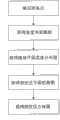
图1是根据本发明的一个实施例的在煤炭地下气化过程中实时获得燃空区形状的方法的步骤的流程图;Fig. 1 is a flow chart of the steps of the method for obtaining the shape of the burn-off zone in real time during the underground coal gasification process according to an embodiment of the present invention;
图2是根据本发明的一个实施例的在煤层中布置热电偶的示意图;Fig. 2 is a schematic diagram of arranging thermocouples in a coal seam according to an embodiment of the present invention;
图3是一个煤层平面中的热电偶测温点的分布及温度的图示;Fig. 3 is the diagram of distribution and temperature of thermocouple temperature measuring points in a coal seam plane;
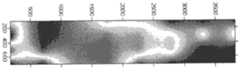
图4是对附图3中的数据进行计算机软件处理后获得的水平煤层平面的平面温度场的图示;Fig. 4 is the graphic representation of the plane temperature field of the horizontal coal seam plane obtained after computer software processing is carried out to the data in accompanying drawing 3;
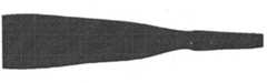
图5是根据图4的水平煤层平面的温度分布图获得的水平煤层平面的燃空区平面轮廓图;Fig. 5 is the plane profile diagram of the burn-out area of the horizontal coal seam plane obtained according to the temperature distribution diagram of the horizontal coal seam plane of Fig. 4;
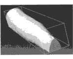
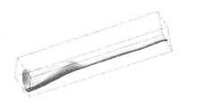
图6是对多个如图5所示的水平煤层平面的燃空区平面轮廓图进行计算机软件处理后获得的燃空区的立体图;Fig. 6 is the three-dimensional view of the burnt-out zone obtained after computer software processing is carried out to the burn-up-out zone plane profile diagram of a plurality of horizontal coal seam planes as shown in Fig. 5;
图7是根据燃煤体积对图6修正后得到的燃空区的立体图;Fig. 7 is a perspective view of the burnt-out zone obtained after correcting Fig. 6 according to the coal-burning volume;
图8类似于图4,但是为垂直煤层平面的平面温度场的图示;Figure 8 is similar to Figure 4, but is an illustration of the plane temperature field perpendicular to the plane of the coal seam;
图9类似于图5,但是为垂直煤层平面的燃空区平面轮廓图;Fig. 9 is similar to Fig. 5, but is a plane profile diagram of the burn-out zone vertical to the coal seam plane;
图10是对多个如图9所示的垂直煤层平面的燃空区平面轮廓图进行计算机软件处理后获得的燃空区的立体图;以及Fig. 10 is a perspective view of the burn-up zone obtained after computer software processing of a plurality of burn-up zone plane outlines of the vertical coal seam plane as shown in Fig. 9; and
图11是根据燃煤体积对图10修正后得到的燃空区的立体图。Fig. 11 is a perspective view of the burn-out zone obtained after correcting Fig. 10 according to the coal-burning volume.
具体实施方式Detailed ways
以下仅通过例子说明本发明的具体实施方式。本发明亦可通过其它不同的方式加以施行或应用,本说明书中的各项细节亦可在不悖离本发明的总体构思的情况下进行各种调整与变更。再者,附图仅以示意方式说明本发明的基本构想,而非用于限制本发明。The specific implementation manners of the present invention are described below only by way of example. The present invention can also be implemented or applied in other different ways, and various adjustments and changes can be made to the details in this specification without departing from the general concept of the present invention. Furthermore, the accompanying drawings illustrate the basic idea of the present invention only in a schematic manner, and are not intended to limit the present invention.
图1是根据本发明的一个实施例的在煤炭地下气化过程中实时获得燃空区形状的方法的步骤的流程图。如图1所示,本发明的在煤炭地下气化过程中实时获得燃空区形状的方法,包括以下步骤:第一步:确定多个煤层平面,在每个煤层平面中确定多个测温点,并确定每个测温点的坐标数据;第二步:在煤炭地下气化过程中实时测量各个测温点的温度数据;第三步:根据不同煤层平面中的各个测温点的坐标数据和温度数据获得各个煤层平面的温度分布图;第四步:根据各个煤层平面的温度分布图获得各个煤层平面的燃空区平面轮廓图;以及第五步:根据各个煤层平面的燃空区平面轮廓图获得燃空区的立体图。Fig. 1 is a flow chart of the steps of the method for obtaining the shape of the burn-off zone in real time during the underground coal gasification process according to an embodiment of the present invention. As shown in Fig. 1, the method for obtaining the shape of the burn-out zone in real time during the underground coal gasification process of the present invention includes the following steps: the first step: determine a plurality of coal seam planes, and determine a plurality of temperature measurements in each coal seam plane point, and determine the coordinate data of each temperature measurement point; the second step: measure the temperature data of each temperature measurement point in real time during the underground coal gasification process; the third step: according to the coordinates of each temperature measurement point in different coal seam planes Data and temperature data to obtain the temperature distribution map of each coal seam plane; the fourth step: according to the temperature distribution map of each coal seam plane to obtain the plane outline map of the burn-up area of each coal seam plane; and the fifth step: according to the burn-up area of each coal seam plane Plane contour plots obtain a stereoscopic view of the burnout zone.
以下参照图2-7并结合煤炭气化过程详细说明根据本发明的一个实施例的实时获得燃空区形状的方法。The method for obtaining the shape of the burn-off zone in real time according to an embodiment of the present invention will be described in detail below with reference to FIGS. 2-7 and in conjunction with the coal gasification process.
首先,在气化过程开始之前,在煤炭气化炉的炉膛中布置煤层及其外围的水泥层和黄土,填满整个炉膛,并且在煤层1中预置热电偶2,如图2所示。可以确定多个煤层平面,在每个煤层平面中确定多个测温点,在每个测温点处布置热电偶,用于在煤炭气化过程中实时地对各个测温点的温度进行测量,以便对炉内气化工况进行监测和调整。热电偶或测温点可以均匀分布或不均匀分布,但是需要有一定的密度,最少需0.5m间距上有一测温点。热电偶可以连接到气化炉外的数显仪表上,在该数显仪表上可显示各个测温点的位置分布及其温度。当然,热电偶只是温度测量仪器的一个例子,可以采用其它的耐高温和高压的温度测量仪器进行温度测量。First, before the gasification process starts, the coal seam and its surrounding cement layer and loess are arranged in the furnace of the coal gasifier to fill the entire furnace, and a
在煤层中布置好热电偶后,设定固定的笛卡尔三维坐标系,并参照该坐标系确定各个测温点的坐标数据。热电偶或测温点可以被预先编号。After the thermocouples are arranged in the coal seam, a fixed Cartesian three-dimensional coordinate system is set, and the coordinate data of each temperature measurement point is determined by referring to the coordinate system. Thermocouples or measuring points can be pre-numbered.
然后,密封炉膛,点燃煤层,通过进气孔注入气化剂,使煤层燃烧并气化,并通过排气孔排出生成的煤气。在此过程中,一部分煤燃烧气化,形成燃空区。Then, the furnace is sealed, the coal seam is ignited, the gasification agent is injected through the air inlet hole, the coal seam is burned and gasified, and the generated coal gas is discharged through the exhaust hole. During this process, part of the coal is combusted and gasified, forming a burn-out zone.
在上述煤炭气化过程中,通过预先布置在煤层中的热电偶实时地测量各个测温点处的温度数据,并显示在数显仪表上,如图3所示。图3显示了一个煤层平面中的测温点的实际分布位置及其温度。图中每一个数据点代表一个测温点,在数据点旁边标注了其编号和温度。During the above-mentioned coal gasification process, the temperature data at each temperature measurement point is measured in real time by the thermocouples pre-arranged in the coal seam, and displayed on the digital display instrument, as shown in Figure 3. Figure 3 shows the actual distribution position and temperature of temperature measuring points in a coal seam plane. Each data point in the figure represents a temperature measurement point, and its number and temperature are marked next to the data point.
然后,根据如图3所示的各个测温点的坐标数据和温度数据,可以获得整个煤层平面的温度分布图。关于这一点,可以根据最小二乘法原理,采用各种数据拟合方法对各个观测数据点进行拟合,以得出整个煤层平面的温度分布图,如图4所示。图4显示的是一个煤层平面的温度分布图,其中的横坐标和纵坐标分别代表煤层平面的长度方向和宽度方向上的坐标。根据本发明的一个实施例,采用计算机数据处理软件来绘制各个煤层平面的温度分布图,即,将各个测温点的坐标数据和温度数据输入计算机,通过计算机数据处理软件绘制出煤层平面的温度分布图。所采用的计算机数据处理软件可以是Surfer、MATLAB等。但是不限于此,其它的能够对测量数据进行拟合的软件也可以使用。Then, according to the coordinate data and temperature data of each temperature measuring point as shown in Figure 3, the temperature distribution map of the entire coal seam plane can be obtained. Regarding this point, according to the principle of the least square method, various data fitting methods can be used to fit each observed data point to obtain the temperature distribution map of the entire coal seam plane, as shown in Figure 4. Figure 4 shows a temperature distribution map of a coal seam plane, where the abscissa and ordinate represent the coordinates in the length direction and width direction of the coal seam plane, respectively. According to one embodiment of the present invention, computer data processing software is used to draw the temperature distribution map of each coal seam plane, that is, the coordinate data and temperature data of each temperature measuring point are input into the computer, and the temperature of the coal seam plane is drawn by computer data processing software Distribution. The computer data processing software used can be Surfer, MATLAB, etc. But it is not limited thereto, and other software that can fit the measurement data can also be used.
在获得如图4所示的煤层平面的温度分布图之后,可以根据该温度分布图,获得一个煤层平面的燃空区平面轮廓图。其原理是:假设煤的燃烧温度为一预定温度,如800℃(不同煤种燃烧温度不同),则可以认为800℃对应的测温点处的煤大致处于气化和非气化的边界点,因此,800℃的等温线对应燃空区的边界。因此,从如图4所示的煤层平面的温度分布图中提取出800℃的数据点(或者去除800℃以上或以下的数据点),绘出等温曲线图,可作为燃空区的平面轮廓图。图5显示了去除例如800℃以下的数据点后得到的燃空区的平面轮廓图。After the temperature distribution diagram of the coal seam plane as shown in FIG. 4 is obtained, a plane profile diagram of the burn-out area of the coal seam plane can be obtained according to the temperature distribution diagram. The principle is: assuming that the combustion temperature of coal is a predetermined temperature, such as 800°C (different coal types have different combustion temperatures), it can be considered that the coal at the temperature measurement point corresponding to 800°C is roughly at the boundary point of gasification and non-gasification , so the 800°C isotherm corresponds to the boundary of the burn-out zone. Therefore, extract the data points at 800°C (or remove the data points above or below 800°C) from the temperature distribution diagram of the coal seam plane as shown in Figure 4, and draw the isothermal curve, which can be used as the plane profile of the burn-out zone picture. Figure 5 shows a planar profile of the burn-out region obtained after removing data points, eg, below 800°C.
但是,上述方法比较粗略,没有考虑热影响区的影响。实际上,由于煤炭燃烧具有一定的热影响区,处于热影响区中的煤可能达到了燃烧温度,但并没有接触气化剂而燃烧。并且,处于煤层不同位置处的热影响区的范围不同。However, the above method is relatively rough and does not consider the influence of the heat-affected zone. In fact, because coal combustion has a certain heat-affected zone, the coal in the heat-affected zone may reach the combustion temperature, but it does not burn without contacting the gasification agent. Moreover, the range of the heat-affected zone at different positions of the coal seam is different.
为克服上述问题,本发明优选采用100℃作为分界点,从温度分布图中去除0~100℃的温度,绘出100℃的等温曲线图,作为粗略的燃空区平面轮廓图,如图5所示。之所以采用100℃为界,是考虑到煤层失水一般是在大于100℃时,即温度大于100℃煤内水分才会向外散失,导致煤体性质开始发生变化,与原煤区别开来,因此认为煤层温度场中处于100℃的边界为热影响区域的边界。在此基础上,估算出煤层热影响区域的长度,将根据100℃绘制的燃空区平面轮廓图的边界沿切线方向向内缩小热影响区域的长度,获得修正的燃空区平面轮廓图,该修正的燃空区平面轮廓图更接近于实际的燃空区形状。In order to overcome the above-mentioned problems, the present invention preferably adopts 100°C as the cut-off point, removes the temperature of 0-100°C from the temperature distribution diagram, and draws an isothermal curve at 100°C as a rough plane profile of the burn-out zone, as shown in Figure 5 shown. The reason why 100°C is used as the boundary is that the dehydration of coal seams generally occurs when the temperature is greater than 100°C, that is, the moisture in the coal will lose outward when the temperature is greater than 100°C, which will cause the properties of the coal body to change, which is different from the original coal. Therefore, it is considered that the boundary at 100°C in the coal seam temperature field is the boundary of the heat-affected zone. On this basis, the length of the heat-affected zone of the coal seam is estimated, and the length of the heat-affected zone is reduced inward along the tangential direction according to the boundary of the planar outline map of the burn-up zone drawn at 100°C, and the corrected planar outline map of the burn-up zone is obtained. The modified planar profile of the burn-off zone is closer to the actual shape of the burn-off zone.
影响热影响区长度的因素很多,比如煤层渗透性、煤层性质、温度和受热时间等。其中,本发明的发明人发现,测温点与煤气出口间的水平距离对热影响区长度的影响较大,因此作为估算煤层热影响区域长度y的主要因素。本发明经过实验研究得出的计算热影响区域的长度y的经验公式为:There are many factors that affect the length of heat-affected zone, such as coal seam permeability, coal seam properties, temperature and heating time, etc. Among them, the inventors of the present invention found that the horizontal distance between the temperature measuring point and the gas outlet has a great influence on the length of the heat-affected zone, so it is used as the main factor for estimating the length y of the heat-affected zone of the coal seam. The empirical formula for calculating the length y of the heat-affected zone obtained through experimental research in the present invention is:
y=0.15088x-19.9578y=0.15088x-19.9578
其中,y为热影响区域的长度,x为煤气出口与燃空区平面轮廓图的边界上的测温点的水平距离。Among them, y is the length of the heat-affected zone, and x is the horizontal distance between the gas outlet and the temperature measuring point on the boundary of the plane outline map of the burn-out zone.
以上是获得一个煤层平面的燃空区平面轮廓图的过程。重复以上过程,可获得其它煤层平面的燃空区平面轮廓图。The above is the process of obtaining a plane outline map of the burn-up area of a coal seam plane. By repeating the above process, the plane contour map of the burn-up area of other coal seam planes can be obtained.
在获得了各个煤层平面的燃空区平面轮廓图之后,将各个煤层平面的燃空区平面轮廓图叠加,即可以得到燃空区的立体图,如图6所示。关于这一点,可以利用计算机绘图软件对各个煤层平面的燃空区平面轮廓图进行处理,得到燃空区的立体图。所采用的计算机绘图软件可以是CATIA、PRO/E、SolidWorks等。After obtaining the plane outlines of the burn-up area of each coal seam plane, the plane outline maps of the burn-up area of each coal seam plane can be superimposed to obtain a three-dimensional view of the burn-up area, as shown in Figure 6. Regarding this point, computer graphics software can be used to process the planar outlines of the burn-up zone of each coal seam plane to obtain a three-dimensional view of the burn-up zone. The computer drawing software used can be CATIA, PRO/E, SolidWorks, etc.
受各种因素的影响,采用如上方法获得的燃空区立体图与实际的燃空区立体图可能仍然存在差别。考虑到这一点,本发明优选对采用上述方法获得的燃空区立体图进行修正,以期更符合实际的燃空区形状。本发明采用的修正方法为:根据各个测温点的坐标数据计算所获得的上述燃空区的体积V计,并根据在煤炭地下气化过程中实际燃烧的煤的体积计算燃空区的体积V空,将获得的燃空区的立体图等比缩小或放大V空/V计的比例,从而获得修正的燃空区立体图,如图7所示。Affected by various factors, there may still be differences between the three-dimensional view of the burn-off area obtained by the above method and the actual three-dimensional view of the burn-out area. Considering this point, the present invention preferably corrects the three-dimensional view of the fuel-empty zone obtained by the above method, in order to better conform to the actual shape of the fuel-empty zone. The correction method adopted in the present invention is:calculate the volume V meter of the above-mentioned burnt-out zone obtained according to the coordinate data of each temperature measuring point, and calculate the volume of the burnt-up zone according to the volume of coal actually burned in the underground coal gasification process Vair , the obtained stereogram of the fuel-empty area is scaled down or the ratio of V-air /Vmeter is enlarged, so as to obtain the corrected stereogram of the fuel-empty area, as shown in Figure 7.
其中,根据本发明的一个实施例,燃空区的体积V空可采用如下方法计算:Wherein, according to an embodiment of the present invention, the volumeV of the burn-out zone can be calculated by the following method:
测量生产的煤气体积V煤气(单位:Nm3)、煤气中各含碳组分的体积百分含量(XCO%、XCO2%、XCH4%、X其它)、煤的含碳量Cdaf%(质量百分比)和煤的密度ρ(单位:kg/Nm3),根据碳平衡原理,计算燃烧煤的体积V煤,减去燃烧残留灰分的体积即为燃空区的体积V空(单位:Nm3)。具体如下:Measure the produced gas volume Vgas (unit: Nm3), the volume percentage of each carbon-containing component in the gas (XCO %, XCO2 %, XCH4 %, Xothers ), and the carbon content of coal Cdaf % (mass percentage) and the density ρ (unit: kg/Nm3) of coal, according to the principle of carbon balance, calculate the volume Vcoal of burning coal, subtract the volume of burning residual ash and be the volume Vempty (unit: Nm3) ). details as follows:
根据碳平衡:According to carbon balance:

推导燃空区体积:Derive the volume of the burn-off zone:

其中,Aad%为煤中灰分的体积含量。Wherein, Aad % is the volume content of ash in coal.
其中,V空为燃空区的体积且单位为Nm3,V煤气为生产的煤气体积且单位为Nm3;XCO%、XCO2%、XCH4%、X其它%为煤气中各含碳组分的体积百分含量,ρ为煤的密度且单位为kg/Nm3,Cad%为煤的碳的质量百分比,Aad%为煤中灰分的体积含量。Among them, V empty is the volume of the burn-out area and the unit is Nm3 , V gas is the volume of gas produced and the unit is Nm3 ; XCO %, XCO2 %, XCH4 %, Xother % are the carbon content in the gas The volume percentage of components, ρ is the density of coal and the unit is kg/Nm3 , Cad % is the mass percentage of carbon in coal, and Aad % is the volume content of ash in coal.
以上描述了根据水平煤层平面的测温点的坐标数据和温度测量数据得到燃空区立体图的过程。类似地,根据本发明的另一个实施例,上述过程可以应用于垂直煤层平面。具体过程如图8-11所示。图8类似于图4,但是为若干垂直煤层平面的平面温度场的图示。图9类似于图5,但是为若干垂直煤层平面的燃空区平面轮廓图。图10是对多个如图9所示的垂直煤层平面的燃空区平面轮廓图进行计算机软件处理后获得的燃空区的立体图。图11是根据燃煤体积对图10修正后得到的燃空区的立体图。关于根据垂直煤层平面的测温点的坐标数据和温度测量数据得到燃空区立体图的步骤类似于以下描述的根据水平煤层平面的测温点的坐标数据和温度测量数据得到燃空区立体图的过程,因此这里省略其说明。The above describes the process of obtaining the three-dimensional map of the burn-up area according to the coordinate data and temperature measurement data of the temperature measurement points on the horizontal coal seam plane. Similarly, according to another embodiment of the present invention, the above process can be applied to vertical coal seam planes. The specific process is shown in Figure 8-11. Figure 8 is similar to Figure 4 but is a graphical representation of the planar temperature field for several vertical coal seam planes. Figure 9 is similar to Figure 5, but is a plane profile of the burnout zone for several vertical coal seam planes. FIG. 10 is a perspective view of the burn-up zone obtained after computer software processing of the plane outlines of the burn-up zone in the vertical coal seam plane as shown in FIG. 9 . Fig. 11 is a perspective view of the burn-out zone obtained after correcting Fig. 10 according to the coal-burning volume. The steps of obtaining the three-dimensional map of the burn-up area according to the coordinate data and temperature measurement data of the temperature-measuring points on the vertical coal seam plane are similar to the process of obtaining the three-dimensional map of the burn-up area according to the coordinate data and temperature measurement data of the temperature-measuring points on the horizontal coal seam plane as described below , so its description is omitted here.
由于水平煤层平面的数量较少,根据水平煤层平面的测温点的坐标数据和温度测量数据只能得到较少的水平燃空区平面轮廓图,而垂直煤层平面的数量相对较多,可以得到较多的垂直燃空区平面轮廓图,因此,根据垂直煤层平面的测温点的坐标数据和温度测量数据得到的燃空区立体图更为精确。另外,利用水平煤层平面获得的燃空区形状可以和利用垂直煤层平面获得的燃空区形状相互参照和修正。Due to the small number of horizontal coal seam planes, according to the coordinate data and temperature measurement data of the temperature measurement points on the horizontal coal seam plane, only a small number of horizontal coal seam plane contour maps can be obtained, while the number of vertical coal seam planes is relatively large, which can be obtained There are more plane contour maps of the vertical burn-up zone, so the three-dimensional map of the burn-up zone obtained according to the coordinate data and temperature measurement data of the temperature measurement points on the vertical coal seam plane is more accurate. In addition, the shape of the burn-up zone obtained by using the horizontal coal seam plane can be cross-referenced and corrected with the shape of the burn-up zone obtained by using the vertical coal seam plane.
另外,根据本发明的一个方面,考虑到在气化过程后期,由于气化区后移,造成先前气化的区域温度下降,利用温度分布图获得燃空区形状会出现前一时刻已经确认了是燃空区的位置不再是燃空区,所以,对于气化过程中后一时刻根据温度测量数据获得的燃空区形状,需要根据气化过程中前一时刻的燃空区形状进行修正。即,在后一时刻取得燃空区的形状(例如图5所示的平面轮廓图)之后,保留前一时刻获得的燃空区形状,将后一时刻获得的燃空区形状叠加在前一时刻获得的燃空区形状上,将叠加后的整体燃空区形状作为后一时刻的实际燃空区形状,从而可获得在一段时间内连续形成的燃空区的形状,因此能够了解燃空区的发展趋势。In addition, according to one aspect of the present invention, considering that at the later stage of the gasification process, the temperature of the previous gasification area will drop due to the backward movement of the gasification area, and it has been confirmed at the previous moment that the shape of the burn-out area can be obtained by using the temperature distribution map. The location of the fuel-air zone is no longer the fuel-empty zone, so the shape of the fuel-empty zone obtained from the temperature measurement data at a later moment in the gasification process needs to be corrected according to the shape of the fuel-empty zone at the previous moment in the gasification process . That is, after obtaining the shape of the fuel-empty zone at a later moment (for example, the plane profile shown in Figure 5), the shape of the fuel-empty zone obtained at the previous moment is retained, and the shape of the fuel-empty zone obtained at the later moment is superimposed on the previous one. Based on the shape of the fuel-empty zone obtained at any time, the superimposed overall shape of the fuel-empty zone is used as the actual shape of the fuel-empty zone at the next moment, so that the shape of the fuel-empty zone formed continuously within a period of time can be obtained, so it is possible to understand the development trends in the region.
另外,根据本发明的一个方面,考虑到在气化刚开始的一段时间内,虽然煤层中处于气化区后端的测温点的温度不高,但是由于存在预设的气化通道,并且该气化通道有一定的半径,因此,绘制燃空区立体图时应将气化通道空间计算在内。In addition, according to one aspect of the present invention, it is considered that during the period of time when the gasification begins, although the temperature of the temperature measuring point at the rear end of the gasification zone in the coal seam is not high, due to the existence of the preset gasification channel and the The gasification channel has a certain radius, so the space of the gasification channel should be included in the calculation of the three-dimensional diagram of the burn-out zone.
如上所述,根据本发明的实时获得燃空区形状的方法,利用的是预置在煤层内部用来测量煤层温度的热电偶取得数据,进而预测燃空区的形状。因此,不需要附加的仪器和检测手段,易于实现,成本较低,而且不会破坏炉膛内部构造且不影响煤炭气化过程的正常进行。并且,本发明利用气化过程实时的温度场分布情况,结合热影响区域变化,推导出实时的燃空区形状,再利用实时燃煤量校正燃空区体积的大小,可以准确地得出实时燃空区的发展情况。As mentioned above, according to the method for obtaining the shape of the burn-off zone in real time according to the present invention, the thermocouples preset inside the coal seam to measure the temperature of the coal seam are used to obtain data, and then predict the shape of the burn-off zone. Therefore, no additional instruments and detection means are needed, easy to implement, low cost, and will not damage the internal structure of the furnace and will not affect the normal progress of the coal gasification process. Moreover, the present invention uses the real-time temperature field distribution of the gasification process, combined with the changes in the heat-affected zone, to deduce the real-time shape of the burn-off zone, and then uses the real-time coal consumption to correct the volume of the burn-off zone, so that the real-time Development of the burnout zone.
以上描述仅示例性地说明了本发明的实施例,而非用于限制本发明,熟知本领域的技术人员应明白,在不偏离本发明的实质的情况下,对本发明所作的任何变形都在本发明的范围内。各个附图只是对本发明的示意性说明,并且各个附图可以相互参照或组合。The above descriptions are only exemplary embodiments of the present invention, rather than limiting the present invention, those skilled in the art should understand that without departing from the essence of the present invention, any modification made to the present invention is within within the scope of the present invention. Each drawing is only a schematic illustration of the present invention, and each drawing can refer to or be combined with each other.
Claims (16)

Priority Applications (1)
| Application Number | Priority Date | Filing Date | Title |
|---|---|---|---|
| CN 201010531358CN102465692B (en) | 2010-10-29 | 2010-10-29 | Method for obtaining fuel air region shape in real time in coal underground gasification process |
Applications Claiming Priority (1)
| Application Number | Priority Date | Filing Date | Title |
|---|---|---|---|
| CN 201010531358CN102465692B (en) | 2010-10-29 | 2010-10-29 | Method for obtaining fuel air region shape in real time in coal underground gasification process |
Publications (2)
| Publication Number | Publication Date |
|---|---|
| CN102465692A CN102465692A (en) | 2012-05-23 |
| CN102465692Btrue CN102465692B (en) | 2013-11-06 |
Family
ID=46069772
Family Applications (1)
| Application Number | Title | Priority Date | Filing Date |
|---|---|---|---|
| CN 201010531358ActiveCN102465692B (en) | 2010-10-29 | 2010-10-29 | Method for obtaining fuel air region shape in real time in coal underground gasification process |
Country Status (1)
| Country | Link |
|---|---|
| CN (1) | CN102465692B (en) |
Families Citing this family (11)
| Publication number | Priority date | Publication date | Assignee | Title |
|---|---|---|---|---|
| CN102721485B (en)* | 2012-06-29 | 2014-05-28 | 新奥气化采煤有限公司 | Real-time monitoring method for two-dimensional planar temperature field of underground coal gasification furnace |
| CN103603646B (en)* | 2013-11-27 | 2016-05-18 | 新奥气化采煤有限公司 | Determine method, the Apparatus and system of coal underground gasifying furnace internal combustion dead zone |
| CN104563992B (en)* | 2014-12-22 | 2018-05-15 | 新奥科技发展有限公司 | Underground coal gasification system and control method |
| CN105804717B (en)* | 2016-03-10 | 2018-12-04 | 新奥科技发展有限公司 | The control method of underground gasification |
| WO2018170830A1 (en)* | 2017-03-23 | 2018-09-27 | 陈信平 | Method for increasing production of coal bed gas by injecting high temperature air |
| CN107462222A (en)* | 2017-07-25 | 2017-12-12 | 新疆国利衡清洁能源科技有限公司 | Mapping system and mapping method for underground coal gasification combustion space area |
| CN107630694B (en)* | 2017-08-22 | 2020-06-16 | 新疆国利衡清洁能源科技有限公司 | Method for obtaining volume of underground coal gasification combustion space area |
| CN115539009B (en)* | 2022-10-17 | 2024-05-31 | 安徽理工大学 | A test system and method for measuring underground coal gasification efficiency |
| CN115577555B (en)* | 2022-10-28 | 2025-08-19 | 中国矿业大学 | Method for estimating loss amount of coal caused by underground coal fire |
| CN116804361B (en)* | 2023-06-26 | 2023-12-12 | 中国矿业大学(北京) | Overlying rock layer temperature monitoring method, system, electronic equipment and storage medium |
| CN120537534B (en)* | 2025-07-25 | 2025-09-30 | 贵州大学 | A stability monitoring and evaluation method for underground coal gasification process |
Citations (4)
| Publication number | Priority date | Publication date | Assignee | Title |
|---|---|---|---|---|
| US4199026A (en)* | 1978-07-17 | 1980-04-22 | Standard Oil Company | Method for detecting underground conditions |
| US6991045B2 (en)* | 2001-10-24 | 2006-01-31 | Shell Oil Company | Forming openings in a hydrocarbon containing formation using magnetic tracking |
| CN101113670A (en)* | 2007-09-04 | 2008-01-30 | 新奥能源研究院有限公司 | An underground coal gasification process |
| CN101649735A (en)* | 2009-06-24 | 2010-02-17 | 新奥科技发展有限公司 | Method, system and device for identifying combustion state of underground coal gasification furnace |
- 2010
- 2010-10-29CNCN 201010531358patent/CN102465692B/enactiveActive
Patent Citations (4)
| Publication number | Priority date | Publication date | Assignee | Title |
|---|---|---|---|---|
| US4199026A (en)* | 1978-07-17 | 1980-04-22 | Standard Oil Company | Method for detecting underground conditions |
| US6991045B2 (en)* | 2001-10-24 | 2006-01-31 | Shell Oil Company | Forming openings in a hydrocarbon containing formation using magnetic tracking |
| CN101113670A (en)* | 2007-09-04 | 2008-01-30 | 新奥能源研究院有限公司 | An underground coal gasification process |
| CN101649735A (en)* | 2009-06-24 | 2010-02-17 | 新奥科技发展有限公司 | Method, system and device for identifying combustion state of underground coal gasification furnace |
Also Published As
| Publication number | Publication date |
|---|---|
| CN102465692A (en) | 2012-05-23 |
Similar Documents
| Publication | Publication Date | Title |
|---|---|---|
| CN102465692B (en) | Method for obtaining fuel air region shape in real time in coal underground gasification process | |
| CN104504755B (en) | Method for stimulating temperature fields of distributed underground facility in mountain body | |
| AU2015345707B2 (en) | Method for determining earth surface interpenetrated crack distribution and air leakage characteristics in shallow burial coal mining | |
| Schoonman et al. | Radial viscous fingering of hot asthenosphere within the Icelandic plume beneath the North Atlantic Ocean | |
| CN102109513B (en) | An experimental device for detecting physical properties of natural gas hydrate in three-dimensional production | |
| CN102721485B (en) | Real-time monitoring method for two-dimensional planar temperature field of underground coal gasification furnace | |
| Okoroafor et al. | Numerical investigation of the impact of fracture aperture anisotropy on EGS thermal performance | |
| CN103603646B (en) | Determine method, the Apparatus and system of coal underground gasifying furnace internal combustion dead zone | |
| Black et al. | Transparent soil to model thermal processes: an energy pile example | |
| Han et al. | Response properties of geometries of coal penetrating fracture on seepage behavior | |
| Xu et al. | Characterization of carbon dioxide leakage process along faults in the laboratory | |
| CN118443564A (en) | A method for determining rock fracture dissolution pattern | |
| Wang et al. | Applicability analysis of thermosyphon for thermally stabilizing pipeline foundation permafrost and its layout optimization | |
| Chang et al. | Diffusion characterization of hydrogen-blended natural gas leakage for buried pipeline based on simulation | |
| Ren et al. | A non-Darcy gas flow model for coalbed methane in mine gobs | |
| Mohanty et al. | CFD modelling of methane dispersion from buried pipeline leaks: Experimental validation and hazard distance estimation | |
| CN104793260A (en) | Method for determining the influence of spontaneous combustion of residual coal on the slope stability of open-pit mine | |
| Shen et al. | Numerical simulation of frost heaving deformation of fractured rocks considering heat-force coupling | |
| Chen et al. | Investigation of nonlinear flow behavior along a rough-walled limestone fracture with acid dissolution | |
| CN108303512A (en) | A kind of method of in-situ test soil-water characteristic curve | |
| CN102567649A (en) | Volume modeling method for coal bed underground combustion space areas | |
| CN102419158B (en) | Method for acquiring shape of combustion space area in underground coal gasification model test furnace | |
| Gao et al. | The relationship between ion current and temperature at the electrode gap | |
| Zhang et al. | Experimental study on the effect of initial water content and temperature gradient on soil column segregation frost heave | |
| CN108087027A (en) | Underground coalfield fire monitoring warning information acquisition and method for early warning |
Legal Events
| Date | Code | Title | Description |
|---|---|---|---|
| C06 | Publication | ||
| PB01 | Publication | ||
| C10 | Entry into substantive examination | ||
| SE01 | Entry into force of request for substantive examination | ||
| C14 | Grant of patent or utility model | ||
| GR01 | Patent grant | ||
| TR01 | Transfer of patent right | ||
| TR01 | Transfer of patent right | Effective date of registration:20170329 Address after:065001 Hebei economic and Technological Development Zone, Langfang science and Technology Park in the Southern District of B building, room 522 Patentee after:ENN SCIENCE & TECHNOLOGY DEVELOPMENT Co.,Ltd. Address before:The 065001 Hebei economic and Technological Development Zone of Langfang Huaxiang new Austrian industrial park south block B Patentee before:ENN SCIENCE & TECHNOLOGY DEVELOPMENT Co.,Ltd. Patentee before:Wulanchabu Xinao Coal Aerification Technology Co., Ltd. |