CN102463907A - Tension balancer - Google Patents
Tension balancerDownload PDFInfo
- Publication number
- CN102463907A CN102463907ACN2011102813987ACN201110281398ACN102463907ACN 102463907 ACN102463907 ACN 102463907ACN 2011102813987 ACN2011102813987 ACN 2011102813987ACN 201110281398 ACN201110281398 ACN 201110281398ACN 102463907 ACN102463907 ACN 102463907A
- Authority
- CN
- China
- Prior art keywords
- frame body
- movable part
- side frame
- coil spring
- tension balancer
- Prior art date
- Legal status (The legal status is an assumption and is not a legal conclusion. Google has not performed a legal analysis and makes no representation as to the accuracy of the status listed.)
- Granted
Links
- 238000009434installationMethods0.000claimsdescription2
- 230000007306turnoverEffects0.000claims2
- 238000003780insertionMethods0.000description8
- 230000037431insertionEffects0.000description8
- 230000008602contractionEffects0.000description4
- 230000002159abnormal effectEffects0.000description3
- 230000008878couplingEffects0.000description2
- 238000010168coupling processMethods0.000description2
- 238000005859coupling reactionMethods0.000description2
- 230000000694effectsEffects0.000description2
- 238000000034methodMethods0.000description1
Images


Classifications
- B—PERFORMING OPERATIONS; TRANSPORTING
- B60—VEHICLES IN GENERAL
- B60M—POWER SUPPLY LINES, AND DEVICES ALONG RAILS, FOR ELECTRICALLY- PROPELLED VEHICLES
- B60M1/00—Power supply lines for contact with collector on vehicle
- B60M1/12—Trolley lines; Accessories therefor
- B60M1/26—Compensation means for variation in length
- B—PERFORMING OPERATIONS; TRANSPORTING
- B60—VEHICLES IN GENERAL
- B60M—POWER SUPPLY LINES, AND DEVICES ALONG RAILS, FOR ELECTRICALLY- PROPELLED VEHICLES
- B60M1/00—Power supply lines for contact with collector on vehicle
- B60M1/12—Trolley lines; Accessories therefor
- B60M1/20—Arrangements for supporting or suspending trolley wires, e.g. from buildings
- B60M1/225—Arrangements for fixing trolley wires to supporting-lines which are under tension
Landscapes
- Engineering & Computer Science (AREA)
- Mechanical Engineering (AREA)
- Suspension Of Electric Lines Or Cables (AREA)
- Springs (AREA)
- Current-Collector Devices For Electrically Propelled Vehicles (AREA)
Abstract
Translated fromChineseDescription
Translated fromChinese技术领域technical field
本发明的实施方式涉及维持架空线的张力的张力平衡器。Embodiment of this invention relates to the tension balancer which maintains the tension|tensile_strength of an overhead wire.
背景技术Background technique
电车经由集电弓(Pantograph)等集电装置从电车线接受电力供给。当由于电车线伴随温度变化而伸缩等,导致电车线的张力变化时,电车线与集电装置之间的接触恶化,有碍于稳定地供给电力。因此,在支柱与电车线之间夹装有用于维持电车线的张力的张力平衡器。The electric train receives power supply from the electric train line via a current collecting device such as a pantograph. When the tension of the trolley wire changes due to the expansion and contraction of the trolley wire due to temperature changes, etc., the contact between the trolley wire and the current collector deteriorates, preventing stable power supply. Therefore, a tension balancer for maintaining the tension of the trolley wire is interposed between the support and the trolley wire.
如图7所示,以往的张力平衡器101具备弹簧盒120、连杆132、螺旋弹簧140、转动臂168、以及框架190等(例如参照专利文献1)。As shown in FIG. 7 , a
弹簧盒120与支柱103并列地沿着铅直方向延伸,通过固定带103a固定于支柱103。连杆132从弹簧盒120的内部插通形成于盖部126的杆插通孔126a而延伸至弹簧盒120的外部。连杆132的下端能旋转地与弹簧承接部134连结,连杆132的上端与转动臂168连结。The
在弹簧盒120的内部收纳有螺旋弹簧140。螺旋弹簧140夹持在盖部126与弹簧承接部134之间,以被压缩的状态收纳于弹簧盒120内。A
框架190固定于弹簧盒120的上端。框架190通过固定带103b固定于支柱103。转动臂168由形成为近似L字状的板构成。转动臂168的角部轴支承于框架190,并且一端与连杆132的上端连结,另一端与电车线102连结。The
张力平衡器101利用螺旋弹簧140的弹力向使连杆132没入弹簧盒120内的方向施力,经由以能够转动的方式被轴支承的转动臂168,向电车线102施加基本恒定的张力。The
专利文献1:日本特开2009-166583号公报Patent Document 1: Japanese Patent Laid-Open No. 2009-166583
在以往的张力平衡器101中,当转动臂168因电车线102的伸缩而以支点182为中心转动时,连杆132一边以自身与弹簧承接部134的连结点138为中心转动,一边相对于弹簧盒120沿进出方向移动。但是,由于弹簧盒120固定于支柱103,因此连杆132的轴向与弹簧盒120的轴向总是不一致,连杆132无法沿着弹簧盒120的轴拉提弹簧承接部134。In the conventional tension balancer 101, when the rotating
因此,弹簧承接部134无法在弹簧盒120内顺畅地滑动,张力平衡器101的功能可能会降低,或者可能会产生异响。并且,由于向螺旋弹簧140施加偏离轴向的力,因此螺旋弹簧140的耐久性可能会降低。Therefore, the
发明内容Contents of the invention
因此,本发明是为了解决上述课题而完成的,其目的在于提供功能、品质良好的张力平衡器。Therefore, this invention was made|formed in order to solve the said subject, and it aims at providing the tension balancer with high function and quality.
为了达到上述目的,本发明的实施方式所涉及的张力平衡器夹装在架空线与支柱之间来维持架空线的张力,上述张力平衡器具有:外侧框体,该外侧框体形成为筒状,其下端轴支承于支柱从而该外侧框体能够倒置设置;内侧可动部,该内侧可动部插通在上述外侧框体内且从上述外侧框体的上端突出,该内侧可动部设置为能够沿上述外侧框体的轴向进出;螺旋弹簧,该螺旋弹簧收纳于上述外侧框体内,对上述内侧可动部朝向进入上述外侧框体内的方向施力;以及转动连结部,该转动连结部具有轴支承于支柱的支点、连结上述内侧可动部的上端的可动部连结点、以及连结架空线的架空线连结点,并且该转动连结部被设置为能够以上述支点为中心转动。In order to achieve the above object, the tension balancer according to the embodiment of the present invention is interposed between the trolley wire and the support to maintain the tension of the trolley wire. The tension balancer has an outer frame formed in a cylindrical shape, Its lower end is pivotally supported on the pillar so that the outer frame can be set upside down; the inner movable part is inserted into the outer frame and protrudes from the upper end of the outer frame, and the inner movable part is configured to be able to In and out along the axial direction of the above-mentioned outer frame body; a coil spring, which is housed in the above-mentioned outer frame body, applies force to the above-mentioned inner movable part toward the direction entering the above-mentioned outer frame body; and a rotating connection part, which has The pivot is supported by the fulcrum of the pillar, the movable part connecting point connecting the upper end of the inner movable part, and the trolley wire connecting point connecting the trolley wire, and the rotation connecting part is provided so as to be rotatable around the fulcrum.
此外,本发明的实施方式所涉及的张力平衡器夹装在架空线与支柱之间来维持架空线的张力,上述张力平衡器具有:外侧框体,该外侧框体形成为筒状;内侧可动部,该内侧可动部插通在上述外侧框体内且从上述外侧框体的下端突出,该内侧可动部的下端轴支承于支柱从而该内侧可动部能够倒置安装,且被设置为能够沿上述外侧框体的轴向进出;螺旋弹簧,该螺旋弹簧收纳于上述外侧框体内,对上述内侧可动部朝向进入上述外侧框体内的方向施力;以及转动连结部,该转动连结部具有轴支承于支柱的支点、连结上述外侧框体的上端的可动部连结点、以及连结架空线的架空线连结点,并且该转动连结部被设置为能够以上述支点为中心转动。In addition, the tension balancer according to the embodiment of the present invention is interposed between the trolley wire and the support to maintain the tension of the trolley wire. The tension balancer includes: an outer frame formed in a cylindrical shape; part, the inner movable part is inserted into the outer frame and protrudes from the lower end of the outer frame, the lower end of the inner movable part is pivotally supported on the pillar so that the inner movable part can be installed upside down, and is arranged to be able to In and out along the axial direction of the above-mentioned outer frame body; a coil spring, which is housed in the above-mentioned outer frame body, applies force to the above-mentioned inner movable part toward the direction entering the above-mentioned outer frame body; and a rotating connection part, which has The pivot is supported by the fulcrum of the pillar, the movable part connection point connected to the upper end of the outer frame, and the trolley wire connection point connected to the trolley wire, and the rotation connection part is provided so as to be rotatable around the fulcrum.
根据本发明,能够提供功能、品质良好的张力平衡器。According to the present invention, it is possible to provide a tension balancer with good functions and high quality.
附图说明Description of drawings
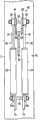
图1是示出本发明第一实施方式所涉及的张力平衡器的安装状态的正视图。FIG. 1 is a front view showing an installed state of a tension balancer according to a first embodiment of the present invention.
图2是沿着图1的箭头II-II方向所见的剖视图。Fig. 2 is a sectional view seen along the arrow II-II direction of Fig. 1 .
图3是本发明第一实施方式所涉及的张力平衡器的平衡器主体的纵剖视图。3 is a longitudinal sectional view of a balancer main body of the tension balancer according to the first embodiment of the present invention.
图4是示出本发明第二实施方式所涉及的张力平衡器的安装状态的正视图。Fig. 4 is a front view showing an installed state of a tension balancer according to a second embodiment of the present invention.
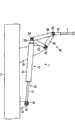
图5是示出本发明第三实施方式所涉及的张力平衡器的安装状态的正视图。Fig. 5 is a front view showing an installed state of a tension balancer according to a third embodiment of the present invention.
图6是本发明第四实施方式所涉及的张力平衡器的平衡器主体的纵剖视图。6 is a longitudinal sectional view of a balancer main body of a tension balancer according to a fourth embodiment of the present invention.
图7是示出以往的张力平衡器的安装状态的正视图。Fig. 7 is a front view showing a conventional tension balancer in an attached state.
图中标号说明:Explanation of symbols in the figure:
1:张力平衡器;2:电车线;2a:连接件;3:支柱;3a:第一支承板;3b:第二支承板;10:平衡器主体;20:外侧框体;22:筒部;24:第一盖部;24a:安装板;26:第二盖部;26a:杆插通孔;30:内侧可动部;32:杆部;34:弹簧承接部;36:安装部;40:螺旋弹簧;42:中间弹簧支承体;60:转动连结部;62:第一长板;64:第二长板;66:第三长板;68:转动臂;80、82、84、86:双头螺栓。1: tension balancer; 2: trolley wire; 2a: connector; 3: pillar; 3a: first support plate; 3b: second support plate; 10: balancer main body; 20: outer frame; 22: cylinder ;24: first cover; 24a: mounting plate; 26: second cover; 26a: rod insertion hole; 30: inner movable part; 32: rod; 34: spring receiving part; 36: installation part; 40: coil spring; 42: intermediate spring support body; 60: rotating joint; 62: first long plate; 64: second long plate; 66: third long plate; 68: rotating arm; 80, 82, 84, 86: Stud bolts.
具体实施方式Detailed ways
[第一实施方式][first embodiment]
使用图1~图3对本发明第一实施方式所涉及的张力平衡器进行说明。图1是示出张力平衡器的安装状态的正视图。图2是沿着图1的箭头II-II方向所见的剖视图。图3是平衡器主体的纵剖视图。The tension balancer which concerns on 1st Embodiment of this invention is demonstrated using FIGS. 1-3. FIG. 1 is a front view showing an installed state of a tension balancer. Fig. 2 is a sectional view seen along the arrow II-II direction of Fig. 1 . Fig. 3 is a longitudinal sectional view of the balancer main body.
本实施方式所涉及的张力平衡器1是电车线用张力平衡器1。张力平衡器1夹装在支柱3等支承体与电车线2之间,由此将电车线2的张力保持为恒定。The tension balancer 1 according to the present embodiment is a
首先,对本实施方式所涉及的张力平衡器1的结构进行说明。First, the structure of the tension balancer 1 which concerns on this embodiment is demonstrated.
如图1以及图2所示,张力平衡器1具备相互平行地配置的两个平衡器主体10、以及两组转动连结部60。As shown in FIGS. 1 and 2 , the
如图3所示,各平衡器主体10具备外侧框体20、内侧可动部30、以及螺旋弹簧40。As shown in FIG. 3 , each balancer
外侧框体20的下端轴支承于支柱3,且能够倒置设置。如图3所示,外侧框体20具有形成为筒状的筒部22、第一盖部24、以及第二盖部26。The lower end of the
第一盖部24封闭筒部22的下端。在第一盖部24一体地设置有从该第一盖部24的下表面突出的安装板24a。在安装板24a形成有贯通孔。The
在支柱3形成有向电车线2延伸的方向突出的两张第一支承板3a。在两张第一支承板3a形成有贯通孔。如图2所示,一个双头螺栓80插通于两个外侧框体20的安装板24a的贯通孔和两张第一支承板3a的贯通孔,由此,外侧框体20被轴支承为能够以双头螺栓80为支点相对于支柱3转动。Two
第二盖部26封闭筒部22的上端,成为螺旋弹簧40的弹簧座。在第二盖部26形成有供后述内侧可动部30的杆部32插通的杆插通孔26a。The
内侧可动部30插通在外侧框体20内,并且被设置成从外侧框体20的上端突出并能够沿外侧框体20的轴向进出。内侧可动部30具有杆部32、弹簧承接部34、以及安装部36。The inner
杆部32形成为棒状,沿外侧框体20的轴中心延伸。杆部32从外侧框体20的内部插通第二盖部26的杆插通孔26a,并从外侧框体20的上端突出。The
弹簧承接部34固定于杆部32的下端,成为螺旋弹簧40的弹簧座。安装部36设置于杆部32的上端。The
螺旋弹簧40被收纳于外侧框体20内。螺旋弹簧40沿外侧框体20的轴向以螺旋状延伸。螺旋弹簧40夹持在外侧框体20的第二盖部26与内侧可动部30的弹簧承接部34之间,以被压缩的状态收纳于外侧框体20内。即,螺旋弹簧40向使内侧可动部30没入外侧框体20内的方向施力。The
如图1所示,一组转动连结部60具有三张长板(第一长板62、第第二长板64、第三长板66)。在三张长板62、64、66的两端部分别形成有贯通孔。后述的双头螺栓82插通于第一长板62的第二端部与第二长板64的第一端部,双头螺栓84插通于第二长板64的第二端部与第三长板66的第一端部、双头螺栓86插通于第三长板66的第二端部与第一长板62的第一端部,由此,三张长板62、64、66组成三角形状。As shown in FIG. 1 , one set of
在支柱3形成有向电车线2延伸的方向突出的一张第二支承板3b。第二支承板3b形成在比第一支承板3a高的位置。在第二支承板3b形成有贯通孔。如图2所示,一个双头螺栓82插通于两组转动连结部60的第一长板62的贯通孔和第二长板64的贯通空以及第二支承板3b的贯通孔,由此,转动连结部60被轴支承为能够以双头螺栓82为支点相对于支柱3转动。One sheet of
一个双头螺栓84插通于两个内侧可动部30的安装部36的贯通孔、和两组转动连结部60的第一长板62的贯通孔以及第三长板66的贯通孔,由此,内侧可动部30与转动连结部60连结。One
在电车线2的端部固定有连接件2a。在连接件2a形成有贯通孔。一个双头螺栓86插通于电车线2的连接件2a的贯通孔、和两组转动连结部60的第二长板64的贯通孔以及第三长板66的贯通孔,由此电车线2与内侧可动部30连接。
接下来,对本实施方式所涉及的张力平衡器1的作用、效果进行说明。Next, the action and effect of the
对于张力平衡器1,当电车线2伸缩时,转动连结部60以支点82为中心转动,伴随与此,内侧可动部30沿着外侧框体20的轴移动,将电车线2的张力保持为基本恒定。In the
在此,如上述那样,在以往的张力平衡器101中,当转动臂168因电车线102的伸缩而以支点182为中心转动时,连杆132一边以自身与弹簧承接部134的连结点138为中心转动,一边相对于弹簧盒120沿进出方向移动。但是,由于弹簧盒120固定于支柱103,因此连杆132的轴向与弹簧盒120的轴向总是不一致,连杆132无法沿弹簧盒120的轴拉提弹簧承接部134。Here, as described above, in the
因此,弹簧承接部134无法在弹簧盒120内顺畅地滑动,张力平衡器101的功能可能会降低,或者可能会产生异响。并且,由于对螺旋弹簧140施加有偏离轴向的力,因此螺旋弹簧140的寿命可能会变短。Therefore, the
另一方面,在本实施方式所涉及的张力平衡器1中,外侧框体20的安装板24a以双头螺栓80为中心轴支承于第一支承板3a,平衡器主体10被安装成能相对于支柱3转动。因此,当转动连结部60因电车线2的伸缩而以支点82为中心转动,转动连结部60与内侧可动部30的连结点84转动时,伴随与此,平衡器主体10以双头螺栓80为中心转动。进而,内侧可动部30总是沿着外侧框体20的轴移动。On the other hand, in the
因此,根据本实施方式所涉及的张力平衡器1,与以往的张力平衡器101相比,弹簧承接部34能够在外侧框体20内顺畅地滑动,更容易发挥张力平衡器1的功能,不容易产生因弹簧承接部34的滑动导致的异响。此外,根据本实施方式,由于相对于螺旋弹簧40总是施加轴向的力,因此能够提高螺旋弹簧40的耐久性。Therefore, according to the
并且,在以往的张力平衡器101中,连杆132以自身与弹簧承接部134的连结点138为中心转动。因此,需要在弹簧盒120的盖部126形成容许连杆132转动的足够的尺寸的杆插通孔126a。其结果是,雨水等容易从间隙进入弹簧盒120内,螺旋弹簧140容易劣化。Furthermore, in the
另一方面,在本实施方式所涉及的张力平衡器1中,由于杆部32的轴向与外侧框体20的轴向总是一致,因此只要将第二盖部26的杆插通孔26a的直径设计为比杆部32的直径略大就够了,由此能够尽可能地减小杆部32与杆插通孔26a之间的间隙。因此,根据本实施方式所涉及的张力平衡器1,与以往的张力平衡器101相比较,雨水等不容易从间隙进入外侧框体20内,螺旋弹簧40不易劣化。On the other hand, in the
此外,在外侧框体20相对于支柱3倾斜的情况下,由于对拉伸电车线2的力加上外侧框体20因自重而倾倒的力(转矩),因此能够将螺旋弹簧40的弹性力设计小一些。因此,能够减小螺旋弹簧40的尺寸,或者放低螺旋弹簧40的材质要求,能够使张力平衡器1小型化、低成本化。In addition, when the
[第二实施方式][Second Embodiment]
使用图4对本发明的第二实施方式所涉及的张力平衡器进行说明。图4是示出张力平衡器的安装状态的正视图。另外,由于本实施方式是第一实施方式的变形例,因此对重复部分标注相同符号,省略上述重复部分的结构的说明。A tension balancer according to a second embodiment of the present invention will be described using FIG. 4 . Fig. 4 is a front view showing an installed state of the tension balancer. In addition, since this embodiment is a modified example of the first embodiment, the same reference numerals are assigned to overlapping portions, and the description of the configuration of the above overlapping portions will be omitted.
在本实施方式中,如图4所示,平衡器主体10以与第一实施方式中的方向上下相反的方式安装。具体地说,外侧框体20的安装板24a与转动连结部60连结,内侧可动部30的安装部36轴支承于支柱3的第一支承板3a。In the present embodiment, as shown in FIG. 4 , the balancer
根据本实施方式,由于第二盖部26的杆插通孔26a配置于下方,因此与第一实施方式相比较,雨水等不容易从杆部32与杆插通孔26a之间的间隙进入外侧框体20内,螺旋弹簧40不容易劣化。According to this embodiment, since the
此外,由于对拉伸电车线2的张力加上外侧框体20的载荷,因此能够将螺旋弹簧40的弹性力设计小一些。因此,能够减小螺旋弹簧40的尺寸,或者放低螺旋弹簧40的材质要求,能够使张力平衡器1小型化、低成本化。In addition, since the load of the
[第三实施方式][Third Embodiment]
使用图5对本发明的第三实施方式所涉及的张力平衡器进行说明。图5是示出张力平衡器的安装状态的正视图。另外,由于本实施方式是第一实施方式的变形例,因此对重复部分标注相同符号,省略该重复部分的结构的说明。A tension balancer according to a third embodiment of the present invention will be described using FIG. 5 . Fig. 5 is a front view showing an installed state of the tension balancer. In addition, since this embodiment is a modified example of the first embodiment, the same reference numerals are assigned to overlapping portions, and the description of the configuration of the overlapping portions will be omitted.
在本实施方式中,如图5所示,使用两个转动臂68作为转动连结部60。转动臂68由形成为大致L字状的板构成。在转动臂68的角部以及两端部分别形成有贯通孔。In the present embodiment, as shown in FIG. 5 , two pivot arms 68 are used as the
一个双头螺栓82插通于两个转动臂68的角部的贯通孔与第二支承板3b的贯通孔,由此,转动臂68被轴支承为能够以双头螺栓82为支点相对于支柱3转动。一个双头螺栓84插通于两个内侧可动部30的安装部36的贯通孔和两个转动臂68的一端部的贯通孔,由此,内侧可动部30与转动臂68连结。一个双头螺栓86插通于电车线2的连接件2a的贯通孔和两个转动臂68的另一端部的贯通孔,由此电车线2与转动臂68连接。One
根据本实施方式,也能够获得与第一实施方式同样的效果。According to this embodiment as well, the same effect as that of the first embodiment can be obtained.
[第四实施方式][Fourth embodiment]
使用图6对本发明的第四实施方式所涉及的张力平衡器进行说明。图6是平衡器主体的纵剖视图。另外,由于本实施方式是第一实施方式的变形例,因此对重复部分标注相同符号,省略该重复部分的结构的说明。A tension balancer according to a fourth embodiment of the present invention will be described using FIG. 6 . Fig. 6 is a longitudinal sectional view of the balancer main body. In addition, since this embodiment is a modified example of the first embodiment, the same reference numerals are assigned to overlapping portions, and the description of the configuration of the overlapping portions will be omitted.
在本实施方式中,如图6所示,在外侧框体20内以串联的方式配置有两个螺旋弹簧40。在两个螺旋弹簧40之间配置有中间弹簧承接体42。另外,两个螺旋弹簧40以相互反向卷绕的方式配置。In this embodiment, as shown in FIG. 6 , two
根据本实施方式,与第一实施方式相比,能够对电车线2施加更大的张力。According to the present embodiment, a larger tension can be applied to the
[其他实施方式][Other implementations]
上述实施方式仅是示例,本发明并不限定于此。并且,也可以组合上述实施方式的特征部分。例如,也可以在第二实施方式中采用转动臂68。The above-mentioned embodiments are merely examples, and the present invention is not limited thereto. Furthermore, the characteristic parts of the above-described embodiments may be combined. For example, the pivot arm 68 may also be employed in the second embodiment.
虽然在第一实施方式中使用了两个平衡器主体10,但也可以使用一个或者多个平衡器主体10。并且,虽然使用了两组转动连结部60,但也可以使用一组或者多组转动连结部60。Although two
在第四实施方式中,虽然在外侧框体20内以串联的方式配置有两个螺旋弹簧40,但是也可以使用三个以上螺旋弹簧40。并且,也可以在外侧框体内以并联的方式配置多个螺旋弹簧40。In the fourth embodiment, two
在上述实施方式中,虽然以电车线2为例进行了说明,但本发明也可以使用电车线2以外的架空线,例如电力线。In the above-mentioned embodiment, although the
Claims (4)
Applications Claiming Priority (2)
| Application Number | Priority Date | Filing Date | Title |
|---|---|---|---|
| JP2010251507AJP5432877B2 (en) | 2010-11-10 | 2010-11-10 | Tension balancer |
| JP2010-251507 | 2010-11-10 |
Publications (2)
| Publication Number | Publication Date |
|---|---|
| CN102463907Atrue CN102463907A (en) | 2012-05-23 |
| CN102463907B CN102463907B (en) | 2016-09-14 |
Family
ID=46050558
Family Applications (2)
| Application Number | Title | Priority Date | Filing Date |
|---|---|---|---|
| CN2011203509477UExpired - LifetimeCN202480904U (en) | 2010-11-10 | 2011-09-14 | Tension balancer |
| CN201110281398.7AActiveCN102463907B (en) | 2010-11-10 | 2011-09-14 | Tension balancer |
Family Applications Before (1)
| Application Number | Title | Priority Date | Filing Date |
|---|---|---|---|
| CN2011203509477UExpired - LifetimeCN202480904U (en) | 2010-11-10 | 2011-09-14 | Tension balancer |
Country Status (6)
| Country | Link |
|---|---|
| US (1) | US20130214117A1 (en) |
| EP (1) | EP2639100A4 (en) |
| JP (1) | JP5432877B2 (en) |
| KR (1) | KR101451750B1 (en) |
| CN (2) | CN202480904U (en) |
| WO (1) | WO2012063384A1 (en) |
Cited By (3)
| Publication number | Priority date | Publication date | Assignee | Title |
|---|---|---|---|---|
| CN109888702A (en)* | 2018-12-26 | 2019-06-14 | 金华八达集团有限公司科技信息分公司 | A device for preventing sagging of a cross cable at an important intersection and a method of using the same |
| CN110789404A (en)* | 2019-10-30 | 2020-02-14 | 徐州中能电力科技有限公司 | Supporting mechanism of electrified railway contact net |
| CN113401010A (en)* | 2021-06-16 | 2021-09-17 | 中铁电气化勘测设计研究院有限公司 | Flexible sectional type movable contact net device |
Families Citing this family (4)
| Publication number | Priority date | Publication date | Assignee | Title |
|---|---|---|---|---|
| JP5432877B2 (en)* | 2010-11-10 | 2014-03-05 | 日本発條株式会社 | Tension balancer |
| JP6552214B2 (en)* | 2015-02-20 | 2019-07-31 | 三和テッキ株式会社 | Train line tension balancer |
| EP3061494A1 (en)* | 2015-02-27 | 2016-08-31 | Nihon Kohden Corporation | Link mechanism for arm portion |
| JP7607067B2 (en)* | 2023-03-22 | 2024-12-26 | 株式会社Nippo | Slope work equipment |
Citations (5)
| Publication number | Priority date | Publication date | Assignee | Title |
|---|---|---|---|---|
| US4592697A (en)* | 1983-04-26 | 1986-06-03 | Kabushiki Kaisha Kobe Seiko Sho | Gravity balancing device for rocking arm |
| CN1289904A (en)* | 1999-09-28 | 2001-04-04 | 毛新悦 | Active constant-force disc spring electrified railway contact net tension compensator |
| JP2008075818A (en)* | 2006-09-22 | 2008-04-03 | Nhk Spring Co Ltd | Tensile gas spring and tension gas spring device for railway overhead lines |
| JP2009166583A (en)* | 2008-01-15 | 2009-07-30 | Sanwa Tekki Corp | Tension balancer of trolley wire |
| CN202480904U (en)* | 2010-11-10 | 2012-10-10 | 日本发条株式会社 | Tension balancer |
Family Cites Families (13)
| Publication number | Priority date | Publication date | Assignee | Title |
|---|---|---|---|---|
| GB1226440A (en)* | 1968-12-13 | 1971-03-31 | ||
| US4249585A (en)* | 1979-04-19 | 1981-02-10 | Mellott Hayes R | Log debarking apparatus |
| JPS5651641U (en)* | 1979-09-28 | 1981-05-07 | ||
| US4341335A (en)* | 1980-10-07 | 1982-07-27 | Sistig Corporation | Method and apparatus for controlling tension in a moving material |
| JPS604008B2 (en)* | 1984-03-19 | 1985-02-01 | 日本発条株式会社 | contact line support device |
| FR2597784B1 (en)* | 1986-04-25 | 1990-10-26 | Michelin & Cie | PROCESS AND APPARATUS FOR MANUFACTURING REINFORCEMENTS FOR TIRES |
| US5101735A (en)* | 1990-08-27 | 1992-04-07 | Williams Matti I | Constant tension apparatus and method with eccentric cam to regulate tension |
| WO1999012762A1 (en)* | 1996-03-04 | 1999-03-18 | Central Japan Railway Company | An aerial line tensioning device |
| US6138964A (en)* | 1999-03-22 | 2000-10-31 | E & E Engineering, Inc. | Material handling unit with readily-removable bearing assembly |
| JP4628941B2 (en)* | 2005-12-08 | 2011-02-09 | 本田技研工業株式会社 | Electric motor control device |
| JP4462634B2 (en)* | 2007-06-20 | 2010-05-12 | 生 西村 | Tension balancer for overhead wire |
| JP5036063B2 (en)* | 2008-06-10 | 2012-09-26 | 日本発條株式会社 | Tension balancer device for overhead wire and tension balancer waterproof cover for overhead wire |
| US9133762B2 (en)* | 2009-09-18 | 2015-09-15 | GM Global Technology Operations LLC | Drive belt tensioner for motor generator unit |
- 2010
- 2010-11-10JPJP2010251507Apatent/JP5432877B2/enactiveActive
- 2011
- 2011-08-03KRKR1020137008709Apatent/KR101451750B1/ennot_activeExpired - Fee Related
- 2011-08-03WOPCT/JP2011/004392patent/WO2012063384A1/enactiveApplication Filing
- 2011-08-03EPEP20110839583patent/EP2639100A4/ennot_activeWithdrawn
- 2011-09-14CNCN2011203509477Upatent/CN202480904U/ennot_activeExpired - Lifetime
- 2011-09-14CNCN201110281398.7Apatent/CN102463907B/enactiveActive
- 2013
- 2013-04-01USUS13/854,485patent/US20130214117A1/ennot_activeAbandoned
Patent Citations (5)
| Publication number | Priority date | Publication date | Assignee | Title |
|---|---|---|---|---|
| US4592697A (en)* | 1983-04-26 | 1986-06-03 | Kabushiki Kaisha Kobe Seiko Sho | Gravity balancing device for rocking arm |
| CN1289904A (en)* | 1999-09-28 | 2001-04-04 | 毛新悦 | Active constant-force disc spring electrified railway contact net tension compensator |
| JP2008075818A (en)* | 2006-09-22 | 2008-04-03 | Nhk Spring Co Ltd | Tensile gas spring and tension gas spring device for railway overhead lines |
| JP2009166583A (en)* | 2008-01-15 | 2009-07-30 | Sanwa Tekki Corp | Tension balancer of trolley wire |
| CN202480904U (en)* | 2010-11-10 | 2012-10-10 | 日本发条株式会社 | Tension balancer |
Cited By (4)
| Publication number | Priority date | Publication date | Assignee | Title |
|---|---|---|---|---|
| CN109888702A (en)* | 2018-12-26 | 2019-06-14 | 金华八达集团有限公司科技信息分公司 | A device for preventing sagging of a cross cable at an important intersection and a method of using the same |
| CN109888702B (en)* | 2018-12-26 | 2020-07-24 | 金华八达集团有限公司科技信息分公司 | Important intersection cross cable anti-sagging device and using method thereof |
| CN110789404A (en)* | 2019-10-30 | 2020-02-14 | 徐州中能电力科技有限公司 | Supporting mechanism of electrified railway contact net |
| CN113401010A (en)* | 2021-06-16 | 2021-09-17 | 中铁电气化勘测设计研究院有限公司 | Flexible sectional type movable contact net device |
Also Published As
| Publication number | Publication date |
|---|---|
| EP2639100A1 (en) | 2013-09-18 |
| EP2639100A4 (en) | 2014-08-06 |
| JP5432877B2 (en) | 2014-03-05 |
| WO2012063384A1 (en) | 2012-05-18 |
| CN202480904U (en) | 2012-10-10 |
| US20130214117A1 (en) | 2013-08-22 |
| CN102463907B (en) | 2016-09-14 |
| KR20130051496A (en) | 2013-05-20 |
| KR101451750B1 (en) | 2014-10-16 |
| JP2012101667A (en) | 2012-05-31 |
Similar Documents
| Publication | Publication Date | Title |
|---|---|---|
| CN102463907B (en) | Tension balancer | |
| TW201739651A (en) | Bearing temperature detection device for railway vehicle bogies | |
| EP2814685A1 (en) | Segmented collector shoe assembly | |
| CN201151409Y (en) | Integrated axle box body of axle box and rotating arm | |
| CN104840155A (en) | Motor noise reduction structure applied to dust collector | |
| CN102738654A (en) | Rubber flexible electrical connector | |
| CN101183767B (en) | Brush holder | |
| CN212195092U (en) | Intermediate support structure of automobile transmission shaft and automobile | |
| CN113328313A (en) | Current collector and sorting device | |
| CN204333550U (en) | Current collector for trolley line | |
| CN210724117U (en) | Wiring device at deformation joint in suspended ceiling of building | |
| JP6605841B2 (en) | Single arm pantograph for railway vehicles | |
| JP4271004B2 (en) | Pantograph device | |
| JP6875901B2 (en) | Tension balancer | |
| CN100511877C (en) | Carbon brush for an electric machine | |
| WO2020021607A1 (en) | Pantograph | |
| CN209240888U (en) | Current collectors for rail vehicles and rail vehicles | |
| JP4270966B2 (en) | Pantograph device | |
| JP2004147494A (en) | Pantograph device | |
| CN111099256A (en) | A conveying device with detection function for bearing processing | |
| JP4973318B2 (en) | Insulated trolley wire current collector | |
| CN211944936U (en) | Conveying device with detection function for bearing processing | |
| CN110962612B (en) | Current collector for rail vehicle and rail vehicle | |
| US6474821B2 (en) | Adjusting device for motor vehicle outside mirrors | |
| CN219917672U (en) | Elastic sheet structure for electronic and electric contact connection |
Legal Events
| Date | Code | Title | Description |
|---|---|---|---|
| C06 | Publication | ||
| PB01 | Publication | ||
| C10 | Entry into substantive examination | ||
| SE01 | Entry into force of request for substantive examination | ||
| C14 | Grant of patent or utility model | ||
| GR01 | Patent grant |