CN102459667A - Composite cemented carbide rotary cutting tools and rotary cutting tool blanks - Google Patents
Composite cemented carbide rotary cutting tools and rotary cutting tool blanksDownload PDFInfo
- Publication number
- CN102459667A CN102459667ACN2010800313720ACN201080031372ACN102459667ACN 102459667 ACN102459667 ACN 102459667ACN 2010800313720 ACN2010800313720 ACN 2010800313720ACN 201080031372 ACN201080031372 ACN 201080031372ACN 102459667 ACN102459667 ACN 102459667A
- Authority
- CN
- China
- Prior art keywords
- carbide
- sintered
- mixed sintering
- area
- grade
- Prior art date
- Legal status (The legal status is an assumption and is not a legal conclusion. Google has not performed a legal analysis and makes no representation as to the accuracy of the status listed.)
- Granted
Links
- 238000005520cutting processMethods0.000titleclaimsabstractdescription188
- 239000002131composite materialSubstances0.000titleclaimsabstractdescription91
- 239000000203mixtureSubstances0.000claimsabstractdescription84
- 238000004519manufacturing processMethods0.000claimsabstractdescription8
- 238000005245sinteringMethods0.000claimsdescription307
- 238000000034methodMethods0.000claimsdescription68
- 239000002245particleSubstances0.000claimsdescription67
- 239000000843powderSubstances0.000claimsdescription48
- 239000000463materialSubstances0.000claimsdescription42
- XEEYBQQBJWHFJM-UHFFFAOYSA-NIronChemical compound[Fe]XEEYBQQBJWHFJM-UHFFFAOYSA-N0.000claimsdescription38
- 238000002156mixingMethods0.000claimsdescription38
- WFKWXMTUELFFGS-UHFFFAOYSA-NtungstenChemical compound[W]WFKWXMTUELFFGS-UHFFFAOYSA-N0.000claimsdescription37
- 239000000126substanceSubstances0.000claimsdescription32
- 229910052751metalInorganic materials0.000claimsdescription24
- 239000002184metalSubstances0.000claimsdescription24
- 229910045601alloyInorganic materials0.000claimsdescription19
- 239000000956alloySubstances0.000claimsdescription19
- 229910052742ironInorganic materials0.000claimsdescription17
- 150000003624transition metalsChemical class0.000claimsdescription16
- 239000010941cobaltSubstances0.000claimsdescription15
- 229910017052cobaltInorganic materials0.000claimsdescription15
- GUTLYIVDDKVIGB-UHFFFAOYSA-Ncobalt atomChemical group[Co]GUTLYIVDDKVIGB-UHFFFAOYSA-N0.000claimsdescription15
- 229910052723transition metalInorganic materials0.000claimsdescription15
- PXHVJJICTQNCMI-UHFFFAOYSA-NNickelChemical compound[Ni]PXHVJJICTQNCMI-UHFFFAOYSA-N0.000claimsdescription13
- UONOETXJSWQNOL-UHFFFAOYSA-Ntungsten carbideChemical compound[W+]#[C-]UONOETXJSWQNOL-UHFFFAOYSA-N0.000claimsdescription12
- 229910003468tantalcarbideInorganic materials0.000claimsdescription11
- 229910052721tungstenInorganic materials0.000claimsdescription11
- 239000010937tungstenSubstances0.000claimsdescription10
- 229910052804chromiumInorganic materials0.000claimsdescription9
- 239000011651chromiumSubstances0.000claimsdescription9
- 229910052750molybdenumInorganic materials0.000claimsdescription9
- 238000002360preparation methodMethods0.000claimsdescription9
- ZOKXTWBITQBERF-UHFFFAOYSA-NMolybdenumChemical compound[Mo]ZOKXTWBITQBERF-UHFFFAOYSA-N0.000claimsdescription8
- 239000011733molybdenumSubstances0.000claimsdescription8
- VYZAMTAEIAYCRO-UHFFFAOYSA-NChromiumChemical compound[Cr]VYZAMTAEIAYCRO-UHFFFAOYSA-N0.000claimsdescription7
- 229910000640Fe alloyInorganic materials0.000claimsdescription7
- 229910000990Ni alloyInorganic materials0.000claimsdescription7
- 229910052782aluminiumInorganic materials0.000claimsdescription7
- 229910052799carbonInorganic materials0.000claimsdescription7
- 229910052802copperInorganic materials0.000claimsdescription7
- 239000010949copperSubstances0.000claimsdescription7
- UNASZPQZIFZUSI-UHFFFAOYSA-NmethylidyneniobiumChemical compound[Nb]#CUNASZPQZIFZUSI-UHFFFAOYSA-N0.000claimsdescription7
- NFFIWVVINABMKP-UHFFFAOYSA-NmethylidynetantalumChemical compound[Ta]#CNFFIWVVINABMKP-UHFFFAOYSA-N0.000claimsdescription7
- 229910052707rutheniumInorganic materials0.000claimsdescription7
- 229910052709silverInorganic materials0.000claimsdescription7
- MTPVUVINMAGMJL-UHFFFAOYSA-Ntrimethyl(1,1,2,2,2-pentafluoroethyl)silaneChemical compoundC[Si](C)(C)C(F)(F)C(F)(F)FMTPVUVINMAGMJL-UHFFFAOYSA-N0.000claimsdescription7
- ZOXJGFHDIHLPTG-UHFFFAOYSA-NBoronChemical compound[B]ZOXJGFHDIHLPTG-UHFFFAOYSA-N0.000claimsdescription6
- OKTJSMMVPCPJKN-UHFFFAOYSA-NCarbonChemical compound[C]OKTJSMMVPCPJKN-UHFFFAOYSA-N0.000claimsdescription6
- RYGMFSIKBFXOCR-UHFFFAOYSA-NCopperChemical compound[Cu]RYGMFSIKBFXOCR-UHFFFAOYSA-N0.000claimsdescription6
- KJTLSVCANCCWHF-UHFFFAOYSA-NRutheniumChemical compound[Ru]KJTLSVCANCCWHF-UHFFFAOYSA-N0.000claimsdescription6
- XUIMIQQOPSSXEZ-UHFFFAOYSA-NSiliconChemical compound[Si]XUIMIQQOPSSXEZ-UHFFFAOYSA-N0.000claimsdescription6
- BQCADISMDOOEFD-UHFFFAOYSA-NSilverChemical compound[Ag]BQCADISMDOOEFD-UHFFFAOYSA-N0.000claimsdescription6
- 229910026551ZrCInorganic materials0.000claimsdescription6
- OTCHGXYCWNXDOA-UHFFFAOYSA-N[C].[Zr]Chemical compound[C].[Zr]OTCHGXYCWNXDOA-UHFFFAOYSA-N0.000claimsdescription6
- 239000004411aluminiumSubstances0.000claimsdescription6
- XAGFODPZIPBFFR-UHFFFAOYSA-NaluminiumChemical compound[Al]XAGFODPZIPBFFR-UHFFFAOYSA-N0.000claimsdescription6
- 229910052796boronInorganic materials0.000claimsdescription6
- WPBNNNQJVZRUHP-UHFFFAOYSA-Lmanganese(2+);methyl n-[[2-(methoxycarbonylcarbamothioylamino)phenyl]carbamothioyl]carbamate;n-[2-(sulfidocarbothioylamino)ethyl]carbamodithioateChemical compound[Mn+2].[S-]C(=S)NCCNC([S-])=S.COC(=O)NC(=S)NC1=CC=CC=C1NC(=S)NC(=O)OCWPBNNNQJVZRUHP-UHFFFAOYSA-L0.000claimsdescription6
- 229910052759nickelInorganic materials0.000claimsdescription6
- 229910052710siliconInorganic materials0.000claimsdescription6
- 239000010703siliconSubstances0.000claimsdescription6
- 239000004332silverSubstances0.000claimsdescription6
- INZDTEICWPZYJM-UHFFFAOYSA-N1-(chloromethyl)-4-[4-(chloromethyl)phenyl]benzeneChemical compoundC1=CC(CCl)=CC=C1C1=CC=C(CCl)C=C1INZDTEICWPZYJM-UHFFFAOYSA-N0.000claimsdescription5
- WHJFNYXPKGDKBB-UHFFFAOYSA-Nhafnium;methaneChemical compoundC.[Hf]WHJFNYXPKGDKBB-UHFFFAOYSA-N0.000claimsdescription5
- 238000000462isostatic pressingMethods0.000claimsdescription5
- 239000008188pelletSubstances0.000claimsdescription5
- 239000004033plasticSubstances0.000claimsdescription5
- 229920003023plasticPolymers0.000claimsdescription5
- QIJNJJZPYXGIQM-UHFFFAOYSA-N1lambda4,2lambda4-dimolybdacyclopropa-1,2,3-trieneChemical compound[Mo]=C=[Mo]QIJNJJZPYXGIQM-UHFFFAOYSA-N0.000claimsdescription4
- 229910039444MoCInorganic materials0.000claimsdescription4
- UFGZSIPAQKLCGR-UHFFFAOYSA-Nchromium carbideChemical compound[Cr]#C[Cr]C#[Cr]UFGZSIPAQKLCGR-UHFFFAOYSA-N0.000claimsdescription4
- 238000000926separation methodMethods0.000claimsdescription4
- 229910003470tongbaiteInorganic materials0.000claimsdescription4
- 238000010438heat treatmentMethods0.000claimsdescription2
- 239000000123paperSubstances0.000claimsdescription2
- 239000011236particulate materialSubstances0.000claims1
- 150000001247metal acetylidesChemical class0.000abstractdescription14
- 229910000831SteelInorganic materials0.000description21
- 239000010959steelSubstances0.000description21
- 239000000919ceramicSubstances0.000description16
- 238000010276constructionMethods0.000description11
- 230000008569processEffects0.000description11
- 239000004567concreteSubstances0.000description10
- 238000005299abrasionMethods0.000description9
- 150000001875compoundsChemical group0.000description9
- 238000005516engineering processMethods0.000description9
- 230000009467reductionEffects0.000description9
- 239000011230binding agentSubstances0.000description7
- 230000008859changeEffects0.000description7
- 238000005553drillingMethods0.000description7
- 239000011159matrix materialSubstances0.000description7
- 230000015572biosynthetic processEffects0.000description6
- 239000006185dispersionSubstances0.000description6
- 238000005056compactionMethods0.000description5
- 239000000853adhesiveSubstances0.000description4
- 230000001070adhesive effectEffects0.000description4
- 238000006243chemical reactionMethods0.000description4
- 229910052715tantalumInorganic materials0.000description4
- 229910052719titaniumInorganic materials0.000description4
- 239000010936titaniumSubstances0.000description4
- 229910009043WC-CoInorganic materials0.000description3
- 238000005275alloyingMethods0.000description3
- 230000008901benefitEffects0.000description3
- 239000004566building materialSubstances0.000description3
- 239000013078crystalSubstances0.000description3
- 238000000280densificationMethods0.000description3
- 238000013461designMethods0.000description3
- 239000010410layerSubstances0.000description3
- 229910052758niobiumInorganic materials0.000description3
- 239000010955niobiumSubstances0.000description3
- 230000000737periodic effectEffects0.000description3
- 238000012545processingMethods0.000description3
- 238000010079rubber tappingMethods0.000description3
- 230000003068static effectEffects0.000description3
- 229910052720vanadiumInorganic materials0.000description3
- 229910052726zirconiumInorganic materials0.000description3
- 229910000531Co alloyInorganic materials0.000description2
- 208000037656Respiratory SoundsDiseases0.000description2
- RTAQQCXQSZGOHL-UHFFFAOYSA-NTitaniumChemical compound[Ti]RTAQQCXQSZGOHL-UHFFFAOYSA-N0.000description2
- 238000007596consolidation processMethods0.000description2
- 230000000694effectsEffects0.000description2
- 238000003487electrochemical reactionMethods0.000description2
- 230000003628erosive effectEffects0.000description2
- 230000014509gene expressionEffects0.000description2
- 238000000227grindingMethods0.000description2
- 229910052735hafniumInorganic materials0.000description2
- 229910001092metal group alloyInorganic materials0.000description2
- 230000005012migrationEffects0.000description2
- 238000013508migrationMethods0.000description2
- 238000012986modificationMethods0.000description2
- 230000004048modificationEffects0.000description2
- 230000002093peripheral effectEffects0.000description2
- 239000002344surface layerSubstances0.000description2
- GUVRBAGPIYLISA-UHFFFAOYSA-Ntantalum atomChemical compound[Ta]GUVRBAGPIYLISA-UHFFFAOYSA-N0.000description2
- UFHFLCQGNIYNRP-UHFFFAOYSA-NHydrogenChemical compound[H][H]UFHFLCQGNIYNRP-UHFFFAOYSA-N0.000description1
- 101100400378Mus musculus Marveld2 geneProteins0.000description1
- FAPWRFPIFSIZLT-UHFFFAOYSA-MSodium chlorideChemical compound[Na+].[Cl-]FAPWRFPIFSIZLT-UHFFFAOYSA-M0.000description1
- QCWXUUIWCKQGHC-UHFFFAOYSA-NZirconiumChemical compound[Zr]QCWXUUIWCKQGHC-UHFFFAOYSA-N0.000description1
- 230000009471actionEffects0.000description1
- ORILYTVJVMAKLC-UHFFFAOYSA-NadamantaneChemical compoundC1C(C2)CC3CC1CC2C3ORILYTVJVMAKLC-UHFFFAOYSA-N0.000description1
- 229910001573adamantineInorganic materials0.000description1
- 230000006978adaptationEffects0.000description1
- 238000004026adhesive bondingMethods0.000description1
- 235000015895biscuitsNutrition0.000description1
- 239000011449brickSubstances0.000description1
- 239000004568cementSubstances0.000description1
- 229910001567cementiteInorganic materials0.000description1
- JPNWDVUTVSTKMV-UHFFFAOYSA-Ncobalt tungstenChemical compound[Co].[W]JPNWDVUTVSTKMV-UHFFFAOYSA-N0.000description1
- 230000006835compressionEffects0.000description1
- 238000007906compressionMethods0.000description1
- 238000005336crackingMethods0.000description1
- 238000005262decarbonizationMethods0.000description1
- 238000005261decarburizationMethods0.000description1
- 230000002950deficientEffects0.000description1
- 238000011161developmentMethods0.000description1
- 238000009792diffusion processMethods0.000description1
- 238000009826distributionMethods0.000description1
- 239000000428dustSubstances0.000description1
- 229910001651emeryInorganic materials0.000description1
- 238000002474experimental methodMethods0.000description1
- 239000000945fillerSubstances0.000description1
- 230000004907fluxEffects0.000description1
- 238000013467fragmentationMethods0.000description1
- 238000006062fragmentation reactionMethods0.000description1
- VBJZVLUMGGDVMO-UHFFFAOYSA-Nhafnium atomChemical compound[Hf]VBJZVLUMGGDVMO-UHFFFAOYSA-N0.000description1
- 238000005552hardfacingMethods0.000description1
- 229910052739hydrogenInorganic materials0.000description1
- 239000001257hydrogenSubstances0.000description1
- 230000006872improvementEffects0.000description1
- 238000003780insertionMethods0.000description1
- 230000037431insertionEffects0.000description1
- 230000003993interactionEffects0.000description1
- 229910021402lonsdaleiteInorganic materials0.000description1
- 239000000314lubricantSubstances0.000description1
- 238000003754machiningMethods0.000description1
- 229910052748manganeseInorganic materials0.000description1
- 239000011572manganeseSubstances0.000description1
- 238000007734materials engineeringMethods0.000description1
- 238000005088metallographyMethods0.000description1
- 150000002739metalsChemical class0.000description1
- 238000000386microscopyMethods0.000description1
- 238000000465mouldingMethods0.000description1
- GUCVJGMIXFAOAE-UHFFFAOYSA-Nniobium atomChemical compound[Nb]GUCVJGMIXFAOAE-UHFFFAOYSA-N0.000description1
- 239000004482other powderSubstances0.000description1
- 239000005022packaging materialSubstances0.000description1
- 238000012856packingMethods0.000description1
- 230000000149penetrating effectEffects0.000description1
- 230000005501phase interfaceEffects0.000description1
- 230000000704physical effectEffects0.000description1
- 238000007639printingMethods0.000description1
- 230000002035prolonged effectEffects0.000description1
- 230000003014reinforcing effectEffects0.000description1
- 230000003252repetitive effectEffects0.000description1
- 238000007493shaping processMethods0.000description1
- 230000008698shear stressEffects0.000description1
- 239000010944silver (metal)Substances0.000description1
- 235000002639sodium chlorideNutrition0.000description1
- 239000011780sodium chlorideSubstances0.000description1
- 239000007787solidSubstances0.000description1
- 238000003860storageMethods0.000description1
- 238000006467substitution reactionMethods0.000description1
- 238000007514turningMethods0.000description1
- GPPXJZIENCGNKB-UHFFFAOYSA-NvanadiumChemical compound[V]#[V]GPPXJZIENCGNKB-UHFFFAOYSA-N0.000description1
- 239000011800void materialSubstances0.000description1
Images


Classifications
- C—CHEMISTRY; METALLURGY
- C22—METALLURGY; FERROUS OR NON-FERROUS ALLOYS; TREATMENT OF ALLOYS OR NON-FERROUS METALS
- C22C—ALLOYS
- C22C1/00—Making non-ferrous alloys
- C22C1/04—Making non-ferrous alloys by powder metallurgy
- C22C1/05—Mixtures of metal powder with non-metallic powder
- C22C1/051—Making hard metals based on borides, carbides, nitrides, oxides or silicides; Preparation of the powder mixture used as the starting material therefor
- C22C1/053—Making hard metals based on borides, carbides, nitrides, oxides or silicides; Preparation of the powder mixture used as the starting material therefor with in situ formation of hard compounds
- C22C1/055—Making hard metals based on borides, carbides, nitrides, oxides or silicides; Preparation of the powder mixture used as the starting material therefor with in situ formation of hard compounds using carbon
- B—PERFORMING OPERATIONS; TRANSPORTING
- B22—CASTING; POWDER METALLURGY
- B22F—WORKING METALLIC POWDER; MANUFACTURE OF ARTICLES FROM METALLIC POWDER; MAKING METALLIC POWDER; APPARATUS OR DEVICES SPECIALLY ADAPTED FOR METALLIC POWDER
- B22F7/00—Manufacture of composite layers, workpieces, or articles, comprising metallic powder, by sintering the powder, with or without compacting wherein at least one part is obtained by sintering or compression
- B22F7/06—Manufacture of composite layers, workpieces, or articles, comprising metallic powder, by sintering the powder, with or without compacting wherein at least one part is obtained by sintering or compression of composite workpieces or articles from parts, e.g. to form tipped tools
- B22F7/062—Manufacture of composite layers, workpieces, or articles, comprising metallic powder, by sintering the powder, with or without compacting wherein at least one part is obtained by sintering or compression of composite workpieces or articles from parts, e.g. to form tipped tools involving the connection or repairing of preformed parts
- B—PERFORMING OPERATIONS; TRANSPORTING
- B23—MACHINE TOOLS; METAL-WORKING NOT OTHERWISE PROVIDED FOR
- B23B—TURNING; BORING
- B23B27/00—Tools for turning or boring machines; Tools of a similar kind in general; Accessories therefor
- B23B27/14—Cutting tools of which the bits or tips or cutting inserts are of special material
- B—PERFORMING OPERATIONS; TRANSPORTING
- B23—MACHINE TOOLS; METAL-WORKING NOT OTHERWISE PROVIDED FOR
- B23B—TURNING; BORING
- B23B51/00—Tools for drilling machines
- C—CHEMISTRY; METALLURGY
- C22—METALLURGY; FERROUS OR NON-FERROUS ALLOYS; TREATMENT OF ALLOYS OR NON-FERROUS METALS
- C22C—ALLOYS
- C22C29/00—Alloys based on carbides, oxides, nitrides, borides, or silicides, e.g. cermets, or other metal compounds, e.g. oxynitrides, sulfides
- C22C29/02—Alloys based on carbides, oxides, nitrides, borides, or silicides, e.g. cermets, or other metal compounds, e.g. oxynitrides, sulfides based on carbides or carbonitrides
- C22C29/06—Alloys based on carbides, oxides, nitrides, borides, or silicides, e.g. cermets, or other metal compounds, e.g. oxynitrides, sulfides based on carbides or carbonitrides based on carbides, but not containing other metal compounds
- B—PERFORMING OPERATIONS; TRANSPORTING
- B22—CASTING; POWDER METALLURGY
- B22F—WORKING METALLIC POWDER; MANUFACTURE OF ARTICLES FROM METALLIC POWDER; MAKING METALLIC POWDER; APPARATUS OR DEVICES SPECIALLY ADAPTED FOR METALLIC POWDER
- B22F5/00—Manufacture of workpieces or articles from metallic powder characterised by the special shape of the product
- B22F2005/001—Cutting tools, earth boring or grinding tool other than table ware
- Y—GENERAL TAGGING OF NEW TECHNOLOGICAL DEVELOPMENTS; GENERAL TAGGING OF CROSS-SECTIONAL TECHNOLOGIES SPANNING OVER SEVERAL SECTIONS OF THE IPC; TECHNICAL SUBJECTS COVERED BY FORMER USPC CROSS-REFERENCE ART COLLECTIONS [XRACs] AND DIGESTS
- Y10—TECHNICAL SUBJECTS COVERED BY FORMER USPC
- Y10T—TECHNICAL SUBJECTS COVERED BY FORMER US CLASSIFICATION
- Y10T407/00—Cutters, for shaping
- Y10T407/19—Rotary cutting tool
- Y10T407/1946—Face or end mill
- Y—GENERAL TAGGING OF NEW TECHNOLOGICAL DEVELOPMENTS; GENERAL TAGGING OF CROSS-SECTIONAL TECHNOLOGIES SPANNING OVER SEVERAL SECTIONS OF THE IPC; TECHNICAL SUBJECTS COVERED BY FORMER USPC CROSS-REFERENCE ART COLLECTIONS [XRACs] AND DIGESTS
- Y10—TECHNICAL SUBJECTS COVERED BY FORMER USPC
- Y10T—TECHNICAL SUBJECTS COVERED BY FORMER US CLASSIFICATION
- Y10T407/00—Cutters, for shaping
- Y10T407/26—Cutters, for shaping comprising cutting edge bonded to tool shank
- Y—GENERAL TAGGING OF NEW TECHNOLOGICAL DEVELOPMENTS; GENERAL TAGGING OF CROSS-SECTIONAL TECHNOLOGIES SPANNING OVER SEVERAL SECTIONS OF THE IPC; TECHNICAL SUBJECTS COVERED BY FORMER USPC CROSS-REFERENCE ART COLLECTIONS [XRACs] AND DIGESTS
- Y10—TECHNICAL SUBJECTS COVERED BY FORMER USPC
- Y10T—TECHNICAL SUBJECTS COVERED BY FORMER US CLASSIFICATION
- Y10T407/00—Cutters, for shaping
- Y10T407/27—Cutters, for shaping comprising tool of specific chemical composition
- Y—GENERAL TAGGING OF NEW TECHNOLOGICAL DEVELOPMENTS; GENERAL TAGGING OF CROSS-SECTIONAL TECHNOLOGIES SPANNING OVER SEVERAL SECTIONS OF THE IPC; TECHNICAL SUBJECTS COVERED BY FORMER USPC CROSS-REFERENCE ART COLLECTIONS [XRACs] AND DIGESTS
- Y10—TECHNICAL SUBJECTS COVERED BY FORMER USPC
- Y10T—TECHNICAL SUBJECTS COVERED BY FORMER US CLASSIFICATION
- Y10T408/00—Cutting by use of rotating axially moving tool
- Y10T408/78—Tool of specific diverse material
- Y—GENERAL TAGGING OF NEW TECHNOLOGICAL DEVELOPMENTS; GENERAL TAGGING OF CROSS-SECTIONAL TECHNOLOGIES SPANNING OVER SEVERAL SECTIONS OF THE IPC; TECHNICAL SUBJECTS COVERED BY FORMER USPC CROSS-REFERENCE ART COLLECTIONS [XRACs] AND DIGESTS
- Y10—TECHNICAL SUBJECTS COVERED BY FORMER USPC
- Y10T—TECHNICAL SUBJECTS COVERED BY FORMER US CLASSIFICATION
- Y10T408/00—Cutting by use of rotating axially moving tool
- Y10T408/89—Tool or Tool with support
- Y10T408/909—Having peripherally spaced cutting edges
- Y10T408/9095—Having peripherally spaced cutting edges with axially extending relief channel
- Y10T408/9097—Spiral channel
Landscapes
- Chemical & Material Sciences (AREA)
- Engineering & Computer Science (AREA)
- Mechanical Engineering (AREA)
- Materials Engineering (AREA)
- Metallurgy (AREA)
- Organic Chemistry (AREA)
- Composite Materials (AREA)
- Manufacturing & Machinery (AREA)
- Powder Metallurgy (AREA)
- Drilling Tools (AREA)
- Pressure Welding/Diffusion-Bonding (AREA)
Abstract
Translated fromChinese
Description
Technical field
The present invention relates generally to rotary cutting tool and rotary cutting tool blank (blank), it has compound structure, and this compound structure comprises the different compositions and/or the zone of microstructure, the invention still further relates to method involving.The present invention relates more specifically to have multistage sintered carbide (wimet) rotary cutting tool and the blank that is used for rotary cutting tool of compound structure; Wherein at least one zone comprises mixing (hybrid) sintered carbide; This sintered carbide (cemented carbide) comprises cubic carbide (cubic carbide), and the present invention more specifically also relates to the method for making rotary cutting tool and rotary cutting tool blank.Rotary cutting tool of the present invention is applicable to multiple common application, for example, is applicable to boring, fraising (reaming), countersinking (countersinking), counterbore (counterboring) and end mill.
Background technology
Sintered carbide rotary cutting tool (that is, the cutting tool of driven in rotation) uses in cut usually, for example, and boring, fraising, countersinking, counterbore, end mill and tapping (tapping).Traditionally, said instrument is to utilize non-mixing closely knit (solid) monolithic construction (monolithic construction) to make.The production technique of this instrument comprises that fixed metallurgical powder (being made up of granular pottery and metal adhesive) is to process a briquet.This briquet receives sintering has monolithic construction with formation cylindrical tool blank then.As used herein, term " monolithic construction " refers to, and instrument is made up of compact material, and such as sintered carbide, its any working volume place in tool interior has same basically characteristic.After sintering, this instrument blank through suitable cut with the cutting edge of processing rotary cutting tool and the characteristic of other geometry in particular.Rotary cutting tool comprises such as drill bit, end mill, reamer and screw tap.
The rotary cutting tool that is made up of sintered carbide is suitable for many industrial applications, comprises cutting and shaping such as structured materials such as metal, timber and plastics.The instrument of sintered carbide preparation is very important in industry, because tensile strength, wearability and flexible combination, it is these properties of materials.As well known in the art, cemented carbide material comprises at least two phases: at least a hard ceramics component and a kind of softer metal adhesive matrix.Hard ceramics component can be such as the carbide that is the element of IVB within the group vib in the periodictable.Example commonly used is a wolfram varbide.Sticker can be a metal or metal alloy, and the typical case is the alloy of cobalt, nickel, iron or these metals.In the matrix that sticker interconnects on three-dimensional with the zone of ceramics component " glued (cements) ".Sintered carbide can be made through the metallurgical powder mixture (blend) of fixed at least a powdered ceramic composition and at least a powdery metal sticker.
The physics of sintered carbide and chemical property depend in part on each composition of the metallurgical powder that is used for manufactured materials.The character of sintered carbide is by confirming such as the chemical constitution of ceramics component, the particle size of ceramics component, the chemical constitution of sticker and the ratio of sticker and ceramics component.Through changing composition and the component proportions in the metallurgical powder mixture, can prepare, such as drill bit and the such sintered carbide rotary cutting tool of end mill, make it have the peculiar property that meets concrete application.
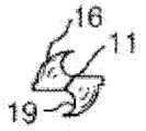
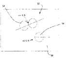
Performance and the range of application of the monolithic construction of rotary cutting tool from having limited cutting tool in essence.As an example, Fig. 1 (a) and 1 (b) illustrate the side-looking and the end view of auger bit 20 respectively, and this drill bit has and is used for generating such as the building material of timber, metal and plastics and the modular design of refine (finishing) eyelet.Auger bit 20 comprises chisel edge (chisel edge) 21, and it is used to realize initial incision workpiece.The cutting torch of drill bit 20 (cutting tip) 24 is with creeping into and remove most materials after chisel edge 21 and along with eyelet.The periphery 26 refine eyelets of cutting torch 24.During working angles, peripheral from the bit central to the drill bit, the cutting speed noticeable change.This phenomenon is shown among Fig. 2 (a) and Fig. 2 (b), and this figure has compared on the cutting torch of typical auger bit the cutting speed of locating at internal diameter (D1), external diameter (D3) and middle footpath (D2) with graphics mode.In Fig. 2 (a), external diameter (D3) is that 1.00 inches and diameter D1 and D2 are respectively 0.25 and 0.50 inch.Fig. 2 (b) shows when auger bit changes operation with PM 200 cutting speed at three different diameter places.Like Fig. 2 (a) with (b), the cutting speed that the difference place measures on the rotary cutting tool cutting edge will increase along with the distance of the turning axle that leaves instrument.
Because these variations on the cutting speed; Drill bit with monolithic construction will can not stand uniform wear at the center of the cutting surface of instrument to the difference place in the outer peripheral scope with other rotary cutting tool, and the fragmentation (chipping) and/or the cracking of this instrument cutting edge also may take place.In addition, when the case-hardened material of drilling, chisel edge is generally in order to penetrating the top layer, and the rest part of drill main body is removed material from the softer core of hardfacing materials.Therefore, the wear rate of chisel edge of conventional non-Mixed drilling bit that is used for the monolithic construction of the case-hardened material of drilling will be much faster than the rest part of cutting edge, cause the working life of this drill bit shorter.Under two kinds of situation because the monolithic construction of conventional non-mixed sintering carbide drill bit, must be often grinding cutting sword again, so just the working life to drill bit has applied tangible restriction.Often grind again and the variation of instrument also can cause too much stoppage time of lathe of using.
The rotary cutting tool with monolithic construction of other type also has similar defective.For example, more custom-designed drill bits are generally used for carrying out simultaneously several work.The instance of this drill bit comprises step drill (step drill) and stepped bit (subland drill).Step drill is processed through on bit diameter, grinding one or more step.This drill bit is used to get out many diameters eyelet.Stepped bit can be in order to accomplish such as several work such as drilling, countersinking and/or counterbore.Like common auger bit, having the classification of common non-mixing monobloc(k)type sintered carbide structure and the service life of stepped bit possibly receive serious limitation owing to the huge difference of the cutting speed that stands in the different cutting edge diameter of drill bit place.
The limitation of monobloc(k)type rotary cutting tool also illustrates aspect end mill.Usually, because the end of cutting tool do not supported, and the length-to-diameter ratio of end mill big (usually greater than 2: 1) usually, so end mill is considered to a kind of invalid metal removal technology.This causes the overbending of end mill and produces serious limit for depth of cut that possibly adopt and rate of feed.
In order to handle the problem relevant, attempt being prepared in the different sites place always and have rotary cutting tool of different nature with the monolithic construction rotary cutting tool.Set forth in USP No. 5609447 and No. 5628837 such as, the sintered carbide drill bit with decarburization surface.In the method among being disclosed in these patents, the carbide drill bit of monobloc(k)type sintered carbide structure is heated between 600-1100 ℃ in the protectiveness environment.This method for preparing the drill bit that hardens has significant limitation.At first, the hardened surface layer of drill bit as thin as a wafer and is quite ground off and is exposed following softer sintered carbide in piece ground.Secondly, in case redressed (redress) when drill bit, hardened surface layer has just completely lost.The 3rd, decarbonization process, it is a kind of additional processing operation, has increased the cost of finished product drill bit widely.
Through using " compound " structure, reduced the relevant limitation of monobloc(k)type sintered carbide rotary cutting tool, for example USP 6511265 (" ' 265 patents ") is disclosed, and it is incorporated herein by reference at this in full.Should ' 265 patent disclose and comprised the composite rotating cutting tool of first area and second area at least.The instrument that is somebody's turn to do ' 265 patent can be processed by sintered carbide; Wherein, The first area of this composite rotating cutting tool comprises first sintered carbide, and it is bonded to the second area of (autogenously bonded to) this instrument from body, and wherein second area comprises second sintered carbide.This first sintered carbide and second sintered carbide be difference to some extent at least a characteristic.This characteristic can for, for example, Young's modulus, hardness, wear resistance, fracture toughness property, tensile strength, erosion resistance, thermal expansivity, perhaps heat-conduction coefficient.The cemented carbide regions in this instrument can be with the coaxial manner setting or is provided with otherwise that thereby can advantageously locate should the zone, thereby can utilize its special nature.
Although invention disclosed has solved some limitation of monobloc(k)type sintered carbide rotary cutting tool in the patent of ' 265, the embodiment that is somebody's turn to do ' 265 patent mainly comprises wolfram varbide.Owing to when in boring, end mill and a type adaptation are used, using rotary cutting tool, generally can run into higher shear-stress, advantageously use sintered carbide grade (grade) with very high strength level, for example, use the sintered carbide of wolfram varbide.Yet these grades possibly not be suitable for the cut Steel Alloy, and this is owing to may react between iron in steel workpiece and the wolfram varbide in the rotary cutting tool.The instrument that is used for the cut steel can contain 0.5% or higher cubic carbide at the conventional grade sintered carbide of monobloc(k)type.Yet, in this instrument, add the reduction that cubic carbide can cause instrument intensity usually.
Thereby, exist in and have the drill bit of different qualities and the needs of other rotary cutting tool on the cutting tool different zones, this characteristic for example be HS and hardness, and its with workpiece generation chemical reaction.
Summary of the invention
According to the present invention, some nonrestrictive embodiments are provided, it relates to a kind of composite product (article), and it can be selected from composite rotating cutting tool and rotary cutting tool blank.This composite product can comprise elongated portion (elongate portion).This elongated portion can comprise first area and second area, and wherein the first area comprises first sintered carbide, and second area is bonded to the first area and comprises second sintered carbide from body.In first sintered carbide and second sintered carbide at least one is the mixed sintering carbide.This mixed sintering carbide comprises cemented dispersed phase and sintered carbide external phase.In cemented dispersed phase and the sintered carbide external phase at least one comprises at least 0.5 weight % cubic carbide, based on the weight of the phase that comprises cubic carbide.
Disclosed some other the unrestriced embodiment of this paper relates to composite product, and it is one of drill bit, drill bit blank, end mill, screw tap and screw tap blank of comprising elongated portion.This elongated portion can comprise first area and second area, and wherein the first area comprises first sintered carbide, and second area is bonded to the first area and comprises second sintered carbide from body.In first sintered carbide and second sintered carbide at least one is the mixed sintering carbide; This mixed sintering carbide comprises sintered carbide discontinuous phase and sintered carbide external phase; Wherein at least one in cemented dispersed phase and the sintered carbide external phase comprises at least 0.5 weight % cubic carbide, based on the gross weight of the phase of the mixed sintering carbide that comprises cubic carbide.In some embodiments, the chemical wear resistance of first sintered carbide is different with the chemical wear resistance of second sintered carbide.
Additional nonrestrictive embodiments more of the present invention relate to a kind of method of article of manufacture, and these goods are selected from composite rotating cutting tool and composite rotating cutting tool blank, and wherein this method comprises, preparation mixed sintering carbide mixture.This mixed sintering carbide mixture can comprise the sintered particles of the first sintered carbide grade and the not sintered particles of the second sintered carbide grade.In one embodiment, at least a in the first sintered carbide grade and the second sintered carbide grade can comprise at least 0.5 weight % cubic carbide, based on the gross weight of this concrete sintered carbide grade.This mixed sintering carbide mixture can be placed in the first area in mould space, and different metallurgical powders can be placed in the second area in space.In one embodiment, at least a portion of this mixed sintering carbide mixture can contact with metallurgical powder.Thereby the embodiment of this method can comprise fixed this mixed sintering carbide mixture and this metallurgical powder and form briquet (compact), this briquet of overvoltage sintering then.
Description of drawings
In conjunction with the drawings, can better understand the disclosed alloy of this paper, the feature and advantage of goods and method, wherein:
The side-view of the auger bit that Fig. 1 (a) illustrates, this fried dough twist brick has common design, and it is used for generating and the refine hole at building material, and this building material for example is a timber, metal and plastics;
Fig. 1 (b) illustrate shown in Fig. 1 (a) the end view of auger bit;
Fig. 2 (a) is a legend, and it illustrates three diameter D1, D2 and D3 along the cutting edge of the non-mixing auger bit of routine;
Fig. 2 (b) is a chart, and it illustrates the cutting speed of conventional non-mixing auger bit at diameter D1, D2 and D3 place;
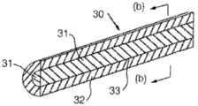
Fig. 3 (a)-(d) is the cross section view of some novel blanks; This blank is used to prepare the composite rotating cutting tool that constructs according to the present invention; And wherein Fig. 3 (a) and 3 (b) illustrate first embodiment, and Fig. 3 (b) is the section end view that the mode with skeleton view is illustrated in the blank among Fig. 3 (a);
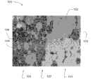
Fig. 4 is the Photomicrograph of the conventional non-mixed sintering carbide grade of prior art, based on carbide and cobalt, and does not have cubic carbide;
Fig. 5 is the Photomicrograph of the conventional non-mixed sintering carbide grade of prior art, based on carbide and cobalt, comprising cubic carbide;
Fig. 6 schematically illustrates the step in abutting connection with rate (contiguity ratio) that is used for confirming mixed sintering carbide disperse phase;
Fig. 7 is the Photomicrograph of mixed sintering carbide, and wherein disperse phase comprises cubic carbide, and external phase does not comprise cubic carbide relatively simultaneously;
Fig. 8 is the Photomicrograph of mixed sintering carbide, and wherein disperse phase does not comprise cubic carbide relatively, and external phase comprises cubic carbide simultaneously;
Fig. 9 is the Photomicrograph in cross section of a kind of embodiment of complex sintered carbide rotary cutting tool; This cutting tool comprises first area and second area; Wherein the first area comprises conventional non-mixed sintering carbide; Second area comprises the mixed sintering carbide, and this mixed sintering carbide comprises that cubic carbide is as disperse phase;
Figure 10 is the Photomicrograph in cross section of a kind of embodiment of complex sintered carbide rotary cutting tool; This cutting tool comprises first area and second area; Wherein the first area comprises the mixed sintering carbide; This mixed sintering carbide comprises cubic carbide as external phase, and second area comprises conventional non-mixed sintering carbide grade;
Figure 11 is the Photomicrograph in cross section of a kind of embodiment of complex sintered carbide rotary cutting tool; This cutting tool comprises first area and second area; Wherein the first area comprises the mixed sintering carbide; This mixed sintering carbide comprises cubic carbide as external phase, and second area comprises the mixed sintering carbide, and this mixed sintering carbide comprises that cubic carbide is as disperse phase; With
Figure 12 is the Photomicrograph in cross section of a kind of embodiment of complex sintered carbide rotary cutting tool; This cutting tool comprises first area and second area; Wherein the first area comprises the conventional non-mixed sintering carbide grade based on wolfram varbide, cubic carbide and cobalt; Second area comprises the mixed sintering carbide, and this mixed sintering carbide comprises cubic carbide in disperse phase, and in external phase, does not have the cubic carbide inclusion basically;
Based on the detailed description of hereinafter to some non-limiting embodiments of the present invention, the reader will be understood that above-mentioned details and other problems.
Detailed Description Of The Invention
In the nonrestrictive embodiment of the present invention, except in practical embodiments or other place that particularly points out, the quantity of all digitized representations and characteristic all should be understood to be in all examples and modify through term " approximately ".Thus, unless otherwise indicated, all digital parameters that provide hereinafter are approximation, and it can change according to the required character that people want in instrument of the present invention, instrument blank and method, to obtain.At least, and be not to attempt to limit the application that is equal to the claim scope, it is to obtain according to the significant figure of being reported and through using conventional choice method that each digital parameters should be interpreted as at least.
Any patent, publication, perhaps other open source information in full or part, as long as it does not conflict with existing definition, summary or other the open material that this paper proposes mutually, is hereby incorporated by.Therefore, and reach required degree, content as herein described can replace any conflict material that is incorporated herein.Any material that this paper is incorporated herein by reference; Perhaps its part, it conflicts with definition as herein described, summary or other open material mutually, in this article; Only wherein a part of scope is introduced, this scope is for introducing the part that does not have conflict between material and the existing open material.
The invention provides rotary cutting tool and cutting tool blank with compound structure, rather than the non-mixing rotary cutting tool of the routine of monolithic construction.As described herein, rotary cutting tool is the cutting tool with at least one cutting edge, removes material thereby it is driven in rotation and contacts from workpiece with workpiece.As described herein, the rotary cutting tool with " compound " structure is meant the rotary cutting tool with at least two zones, and these two zones are different on chemical constitution and/or microstructure, and different at least a characteristic or material character.This characteristic or material character can be selected from, for example, and chemical wear resistance, erosion resistance, hardness, tensile strength, mechanical endurance, fracture toughness property, Young's modulus, thermal expansivity and heat-conduction coefficient.The embodiment of composite rotating cutting tool that can be constructed according to the invention comprises, drill bit and end mill, and for example can be used in other rotary cutting tool of the boring of material, fraising, countersinking, counterbore, end mill and tapping.
According to some embodiments, the invention provides a kind of composite rotating cutting tool, it has at least one cutting edge; Like the directed cutting edge of spiral; And comprise at least two cemented carbide regions, they combine from body, and different each other at least one characteristic or material character.As described herein, " combining " from body be meant below in conjunction with, it takes place between the zone of sintered carbide or another material and does not add filler metal or other flux.
In the embodiment of disclosed composite rotating cutting tool of this paper and composite rotating cutting tool blank, at least one zone of these instruments or blank comprises the mixed sintering carbide.A kind of mixed sintering carbide comprises sintered carbide external phase and cemented dispersed phase.In some embodiments, the sintered carbide external phase of mixed sintering carbide and at least one in the cemented dispersed phase comprise at least 0.5 weight % cubic carbide, based on the gross weight of the phase that comprises this cubic carbide.
The transition metal that belongs to the IVB to VIB of family in the periodic table of elements is that stronger relatively carbide forms thing.The carbide of some formation in these transition metal be characterized as cubic crystal structure, and the carbide that other transition metal forms be characterized as structure of hexagonal crystal.This cubic carbide is compared firmer with the lonsdaleite thing.The transition metal that forms the IVB to VIB of family of cubic carbide is Ti, V, Cr, Zr, Nb, HF and Ta.The carbide of tungsten and molybdenum has structure of hexagonal crystal, and wherein tungsten is the most weak in the carbide formation thing.This cubic carbide is soluble each other and in the compositing range of broad, forms sosoloid each other.In addition, cubic carbide is for WC and Mo2C has significant solvability.On the other hand, WC does not have solvability for any cubic carbide usually.
The best of breed of intensity, wear resistance and fracture toughness property is provided as metal bonding sintered carbide mutually with Co with dispersive based on the WC conduct firmly mutually.During utilizing the cut of WC/Co sintered carbide instrument to Steel Alloy, the Steel Chips that is produced by the cut steel keeps contacting with the WC/Co sintered carbide.When at high temperature contacting with iron, WC is unsettled relatively, thereby during the cut of steel, the depression hole (cratering) and the reduction of WC/Co throw may take place.
Have realized that and add the WC and the interaction of the Fe in the steel that can reduce in cubic carbide to the sintered carbide of WC/Co monobloc(k)type rotary cutting tool in the throw, so when being used for the cut Steel Alloy, prolonged the life-span of instrument.Yet cubic carbide is added the reduction that can cause instrument intensity in these instruments equally to, thereby can cause this instrument to be not suitable for some cut application.
In the embodiment of composite rotating instrument of the present invention or throw blank, the providing of mixed sintering carbide that comprises cubic carbide improved chemical wear resistance, can obviously not reduce the intensity of instrument simultaneously.As described herein, refer to corrosive wear and be meant following wearing and tearing to " chemical abrasion " interchangeableness, tangible chemistry or electrochemical reaction promptly wherein take place between material and workpiece and/or environment, caused the wearing and tearing of material.For example, when this instrument was used for the cut Steel Alloy, because the diffusion and the chemical reaction of wolfram varbide and iron smear metal, chemical abrasion can be observed on rotary cutting tool.
In one embodiment, two of rotary cutting tool can comprise conventional non-mixing grade sintered carbide from one of body bonded cemented carbide regions.The non-mixing grade of a kind of routine sintered carbide can comprise transition metal carbide particle and the matrix metal or the metal alloy of one or more types.In a kind of non-restrictive example, conventional non-mixing grade sintered carbide can comprise the wolfram varbide hard particles, and this wolfram varbide hard particles is embedded in the co binder.A kind of instance of conventional non-mixing grade tungsten-cobalt carbide (being WC-Co) sintered carbide as shown in Figure 4.Sintered carbide shown in this Fig. 4 is through compacting and the preparation of sintering Firth Grade 248 cemented carbide mixtures, and this mixture can be from ATI Firth Sterling, Madison, and Alabama obtains.Firth Grade 248 cemented carbide mixtures comprise about 11 weight % cobalt dusts and 89 weight % tungsten carbide particles (or powder).Sintered carbide through compacting and sintering Firth Grade 248 powdered mixture productions comprises the discontinuous phase that is embedded in the tungsten carbide particle of continuous cobalt binder in mutually.Another kind of conventional non-mixing grade sintered carbide is as shown in Figure 5.Sintered carbide among Fig. 5 is produced (can pass through ATI Firth Sterling equally, Madison, Alabama company obtains) by Firth Grade T-04 cemented carbide mixture.Firth Grade T-04 cemented carbide mixture comprises: the cobalt dust of 12 weight %; Total amount is the titanium carbide of 6 weight %, tantalum carbide, and particles of niobium carbide; And the tungsten carbide particle of 82 weight %.Sintered carbide through compacting and the production of sintering Firth Grade T-04 powdered mixture comprises and is embedded in the discontinuous phase of continuous cobalt binder in mutually that this discontinuous phase comprises tungsten carbide particle and titanium carbide, tantalum carbide and niobium carbide sosoloid.
As indicated above; One embodiment of the present invention relate to a kind of mixture; It comprises the first area of containing the mixed sintering carbide; This mixed sintering carbide comprises the cubic carbide of at least 0.5 weight %, and based on the weight of the phase that comprises this cubic carbide, this first area is bonded to the second area that contains conventional non-mixed sintering carbide from body.In another embodiment; Two each in body bonded cemented carbide regions all contain the mixed sintering carbide; In while two mixed sintering carbide each includes the cubic carbide of at least 0.5 weight %, based on the weight of the mixed sintering carbide phase that comprises this cubic carbide.Only based on the sintered carbide of wolfram varbide and cobalt, each mixed sintering carbide can have the chemical wearability of improvement with respect to for example, and said mixed sintering carbide comprises the phase (based on the gross weight of this phase) that contains at least 0.5% cubic carbide.For example; Comprise the zone that contacts with workpiece when instrument; This zone comprises the mixed sintering carbide; This mixed sintering carbide comprises continuously and/or discontinuous phase, when this comprises at least 0.5% cubic carbide (based on the gross weight of the phase that contains this cubic carbide) mutually, can occur when contact with steel workpiece, since the generation in the depression hole of the sintered carbide instrument that chemical abrasion causes by significantly minimizing.Therefore, in the mixed sintering carbide, contain the chemical wear resistance that cubic carbide can improve the instrument that comprises the zone of containing the mixed sintering carbide.Equally, compare with the instrument of for example being processed by the non-mixing grade of routine WC-Co sintered carbide, the intensity in the mixed sintering carbide zone of this instrument is owing to the existence of cubic carbide can significantly not reduce yet.
Some aspects of embodiments more of the present invention can through with reference to figure 3 (a) and the rotary cutting tool blank 30 (b) be better understood.Fig. 3 (a) is a cross sectional view, and wherein rotary cutting tool blank 30 is cut into section along the plane that comprises the blank hub.Fig. 3 (b) is a cross sectional view, and wherein rotary cutting tool blank 30 is cut into section transverse to the tool focus axle.Rotary cutting tool blank 30 is sintered compacts of general cylindrical, have two coaxial settings, from body bonded cemented carbide regions.Yet, for present technique field personnel, obviously be that the following discussion of embodiment of the present invention also can be suitable for making and has complex geometric shapes more and/or more than the composite rotating cutting tool and the rotary cutting tool blank in two zones.Thereby below discussing is not to be intended to limit the present invention, and is some non-limiting embodiments of illustration the present invention.
Rotary cutting tool blank 30 can comprisefirst area 31, and it can be for comprising the core area of first sintered carbide.In a kind of nonrestrictive embodiment, core area can comprise the conventional non-mixing grade WC-Co sintered carbide that the highest possible intensity is provided.First sintered carbide of thisfirst area 31 combines with the second area that comprisessecond carbide 32, and this second area can be the external region.This external region can comprise the mixed sintering carbide; Wherein continuously with disperse phase at least a at least 0.5% cubic carbide (based on the concrete weight mutually that comprises this cubic carbide) that comprises; Thereby enhanced chemistry wear resistance is provided; Compare with the same sintered carbide that does not contain cubic carbide simultaneously, can not lose intensity and mechanical endurance significantly.Shown in Fig. 3 (a) and 3 (b),first area 31 can coaxially be provided with second area 32.This first andsecond zone
As indicated above, the disclosed embodiment of this paper comprises one or more zones of containing the mixed sintering carbide.Although conventional non-mixed sintering carbide is a kind of matrix material; It generally includes to spread all over and disperses and be embedded in the transition metal carbide particle of continuous bonding in mutually; The zone that the mixed sintering carbide can comprise the non-mixed sintering carbide of at least a routine grade (perhaps; This paper can interchangeability use, " phase "), the non-mixed sintering carbide of this routine grade spreads all over to be disperseed or is embedded in the external phase of the second conventional non-mixed sintering carbide grade; Therefore formed a kind of mixture, it comprises the first sintered carbide discontinuous phase and the second sintered carbide external phase.The mixed sintering carbide is for example open at USP NO.7384443 (" ' 433 patents "), and it is incorporated herein by reference at this in full.The discontinuous sintered carbide of every kind of mixed sintering carbide is mutually common with the stoking carbide mutually; And independently; The carbide particle that comprises one or more transition metal, this transition metal for example is: titanium, vanadium, chromium, zirconium, hafnium, molybdenum, niobium, tantalum and tungsten.Two of mixed sintering carbide also comprises mutually continuous metal bonding phase (or, more simply, continuous metal sticker) respectively, and it will be bonded to together or gluing at concrete all carbide particles in mutually of mixed sintering carbide.The continuous metal bonding of every kind of sintered carbide of mixed sintering carbide can comprise cobalt, cobalt-base alloy, nickel, nickelalloy, iron or iron alloy mutually.Randomly; Alloying element for example; For instance; The bonding that tungsten, chromium, molybdenum, carbon, boron, silicon, copper, manganese, ruthenium, aluminium and silver may reside in the mixed sintering carbide mutually in or be present in two sintered carbides of mixed sintering carbide, strengthen different performances with less relatively concentration.When relating to mixed sintering carbide as herein described, term " disperse phase " and " discontinuous phase " trans-substitution mutually use.
As indicated above; An aspect that can be included in the mixed sintering carbide in the zone of the disclosed composite product of this paper is; The sintered carbide external phase of mixed sintering carbide and at least one among the sintered carbide discontinuous phase comprise the cubic carbide of at least 0.5 weight %, and wherein this weight percent is based on the gross weight of the phase of the mixed sintering carbide that comprises this cubic carbide.
In some embodiments of composite tool of the present invention and blank, it is low in abutting connection with rate that the sintered carbide that is used for some mixed sintering carbide of mixture disperses (discontinuous) to have mutually.Disperse phase in the composite structure in abutting connection with degree can be rule of thumb by in abutting connection with rate CtCharacterize.CtCan confirm that it is described in Underwood through using the quantitative metallography photo technology, Quantitative Microscopy, 279-290 (1968) is incorporated herein by reference this its.Be used to measure CtTechnology exist fully openly in the patent of ' 443, it is incorporated herein by reference at this in full.As known in those skilled in the art; This technology is made up of following: the quantity of intersecting (intersection) of confirming that line and the specific structural features of the random orienting of known length constitute, the line of the random orienting of this known length places on the Photomicrograph of material microstructure.Count this line and disperse phase/disperse phase and intersect the sum (N that intersects that constitutesL α α), likewise calculate the number of crossovers (N at disperse phase/external phase interfaceL α β).Fig. 6 schematically illustrates step, promptly obtains N through these stepsL α αAnd NL α βValue.In Fig. 6,52 ordinary representation mixtures, it comprises thedisperse phase 54 of α phase in continuous β phase 56.In abutting connection with rate CtThrough formula Ct=2NL α α/ (NL α β+ 2NL α α) calculate.
In abutting connection with rate the measuring of average percent of the surface area that contacts of discontinuous (dispersion) region discontinuous with other (dispersion) region.In the distribution of discrete areas from disperseing (C fullyt=0) to assembling (C fullytWhen=1) changing, this ratio can be changed to 1 from 0.This in abutting connection with rate described the volume(tric)fraction of not considering disperse phase area or the size situation under disperse phase in abutting connection with degree.Yet, generally speaking, for comparatively large vol fractional disperse phase, disperse phase also may be higher in abutting connection with rate.
Under the situation of mixed sintering carbide with hard cemented dispersed phase, disperse phase low more in abutting connection with rate, the possibility of hard phase regions that crackle will diffuse through adjacency is low more.This crackle process can be repetitive process, thereby has the reduction that storage effect causes the overall flexibility of complex sintered carbide throw.In a kind of embodiment of complex sintered carbide rotary cutting tool of the present invention or rotary cutting tool blank; The mixed sintering carbide that comprises in this instrument or the biscuit area can comprise cemented dispersed phase; Measure through aforesaid method, its have be not higher than 0.48 in abutting connection with rate.
In some embodiments of complex sintered carbide rotary cutting tool of the present invention or rotary cutting tool blank, the mixed sintering carbide that comprises in the mixture zone can comprise the sintered carbide grade of about 2 to about 40 volume % disperse phase.In another embodiment, this cemented dispersed phase can be 2 to 50% of mixed sintering carbide volume.In another embodiment, this cemented dispersed phase can be 2 to 30% of mixed sintering carbide volume.In other embodiments, possibly desirably be that the cemented dispersed phase of this mixed sintering carbide is 6 to 25% of a mixed sintering carbide volume.
In one embodiment; Sintered carbide in sintered carbide in thefirst area 31 and the second area 32 (the dispersion sintered carbide that comprises the mixed sintering carbide mutually with stoking carbide mutually); Can comprise ceramic composition, this ceramic composition is made up of to the carbide of one or more elements of group vib IVB in the periodic table of elements.
This ceramic composition preferably accounts for about 60 to about 98 weight % of sintered carbide gross weight in each zone.The ceramic composition particle is embedded within the matrix of metal bonding material, and this metal bonding matrix of materials preferably accounts in each zone and always about 2 of sintered carbide arrives about 40 weight %.Sticker is preferably one or more in Co, Co alloy, Ni, Ni alloy, Fe and the Fe alloy.Sticker randomly can also contain such as such as these elements of W, Cr, Ti, Ta, V, Mo, Nb, Zr, Hf and C, and content can be up to the solubility limit of these elements in sticker.In addition, sticker can contain the element such as Cu, Mn, Ag, Al and Ru up to 5 weight percents.In a kind of embodiment of composite rotating cutting tool or rotary cutting tool blank; The sticker of the sticker of first sintered carbide and second sintered carbide can further comprise at least a alloy addition independently, and it is selected from tungsten, chromium, molybdenum, carbon, boron, silicon, copper, manganese, ruthenium, aluminium and silver.The perhaps whole arbitrarily components that those skilled in the art will recognize that sintered carbide can add with element form, compound and/or master alloy.The character of the sintered carbide that uses in the embodiment of the present invention can customize to application-specific, a kind of or its arbitrary combination in the weight ratio of the particle size of its chemical constitution through the change ceramic composition, ceramic composition, the chemical constitution of sticker and binder content and ceramic composition content.
In some embodiments; The disperse phase of the mixed sintering carbide that in the zone of the disclosed composite product of this paper, comprises and at least one in the external phase comprise at least 0.5 weight % cubic carbide; Gross weight based on the phase of the mixed sintering carbide that comprises cubic carbide; Perhaps in other words, based on the weight of the phase that comprises this cubic carbide.In some other embodiments; The disperse phase of the mixed sintering carbide that in the zone of the disclosed composite product of this paper, comprises and at least one in the external phase comprise at least 1.0 weight % cubic carbide, based on the weight of the phase of the mixed sintering carbide that comprises cubic carbide.In one embodiment, the disperse phase of mixed sintering carbide and at least one in the external phase comprise 5% or more cubic carbide, based on the gross weight of the phase that comprises cubic carbide.In other embodiment; The disperse phase of mixed sintering carbide and at least one in the external phase comprise 0.5% to 30%, 1% to 25%, 5% to 25% or the cubic carbide of about 6% weight, based on the gross weight of the phase of the mixed sintering carbide that comprises cubic carbide.
As described herein, " cubic carbide " is meant transition metal carbide, and it has the cubic close packing crystalline structure.This crystalline structure also can be meant face-centered cubic lattice and have cF8Pearson Symbol and the rock salt crystalline structure of B1Strukturbericht sign.In one embodiment, the cubic carbide inclusion of the mixed sintering carbide in the composite product of the present invention zone can comprise that the carbide of one or more transition metal, this transition metal are selected from IV and the V family in the periodic table of elements.In another embodiment, this cubic carbide inclusion can comprise one or more of TiC, TaC, NbC, VC, HfC and ZrC.In another embodiment, this cubic carbide inclusion can comprise one or more of TiC, TaC and NbC.In another embodiment, this cubic carbide inclusion can comprise TiC.In another embodiment, this cubic carbide inclusion can comprise the sosoloid of different cubic carbide.
As indicated above, in embodiments of the present invention, complex sintered carbide rotary cutting tool or rotary cutting tool blank can comprise first area and second area at least.The first area of composite rotating cutting tool or blank comprises first sintered carbide, and it is bonded to the second area that comprises second sintered carbide from body.In some embodiments; At least a mixed sintering carbide that comprises in first sintered carbide and second sintered carbide; This mixed sintering carbide comprises the cubic carbide of at least 0.5 weight %, based on the weight of the phase of the mixed sintering carbide that comprises cubic carbide.In another embodiment, the first area can be substantially devoid of cubic carbide and second area comprises the mixed sintering carbide, and this mixed sintering carbide comprises at least 0.5% cubic carbide, based on the weight of the phase that contains cubic carbide.In another embodiment; The surpassing a zone and can comprise the mixed sintering carbide of composite rotating cutting tool or blank; This mixed sintering carbide comprises the cubic carbide of at least 0.5 weight %, and the content of each cubic carbide is based on the weight of the phase of the mixed sintering carbide that comprises cubic carbide.
As indicated above, the mixed sintering carbide comprises the disperse phase of sintered carbide first grade and the external phase of sintered carbide second grade.In a kind of embodiment of the complex sintered carbide rotary cutting tool of this paper or rotary cutting tool blank; The cubic carbide of all basically mixed sintering carbide can be arranged in the external phase of mixed sintering carbide; Wherein said cutting tool or blank comprise the zone of containing the mixed sintering carbide; This mixed sintering carbide comprises at least 0.5% cubic carbide, based on the weight of the phase that comprises cubic carbide.In another embodiment, the cubic carbide of all basically mixed sintering carbide can be positioned at the mixed sintering carbide discontinuous (dispersion) mutually in.In another embodiment, the disperse phase of mixed sintering carbide and external phase all comprise at least 0.5 weight % cubic carbide, based on the weight of every kind of independent phase.Zone about complex sintered carbide rotary cutting tool of the present invention or blank; Thereby the composition of mixed sintering carbide and/or character can customize as required complex sintered carbide rotary cutting tool or the blank with required mechanical property is provided; Said rotary cutting tool of the present invention or blank comprise the mixed sintering carbide; Wherein this mixed sintering carbide comprises at least 0.5% cubic carbide, based on the weight of the phase that contains this cubic carbide.
Well known in the art, exist cubic carbide can cause the moderate of sintered carbide intensity to reduce in the sintered carbide.In addition, as stated, the strongest sintered carbide grade, it might not be suitable for the cut steel based on WC and Co.This is that this cutting contacts with the sintered carbide of instrument because steel generally produces long continuous chip when cut.Iron in the steel is the potential carbide forming element, and contacting between cutting and carbide can cause WC to be diffused into from instrument in the surface of firm smear metal and with iron generation chemical action.WC can cause the cutting tool reduction and cause the formation of depression at the cutting tool cutting surface from the migration of sintered carbide cutting tool.The interpolation of cubic carbide in the sintered carbide instrument alleviated the migration and the dishing effect of carbide, but the moderate that does not cause instrument intensity reduces.Yet; As teaching herein,, the intensity that the existence of cubic carbide causes in the instrument can minimize through in instrument, comprising the mixed sintering carbide and (disposing) all or part of cubic carbide being set in mixed sintering carbide microstructure because reducing.Cubic carbide through comprising at least 0.5 weight % mixed sintering carbide microstructure mutually in; Can improve the chemical wear resistance of rotary cutting tool; Compare with following rotary cutting tool simultaneously; Can not reduce instrument intensity significantly, said rotary cutting tool is based on only comprising the sintered carbide of wolfram varbide grit as disperse phase.
Through in the mixed sintering carbide of instrument, cubic carbide being set, the reduction on the instrument intensity will be minimized, and the depression of instrument will reduce and cuts when being used for the cut steel simultaneously.Though the embodiment of the composite rotating cutting tool that this paper provides has the individual zone that comprises sintered carbide of limited quantity; But it should be understood that; The rotary cutting tool of this paper can comprise the zone of the sintered carbide of any amount; Comprise the include mixed sintered carbide zone of (containing cubic carbide), and each zone can be configured to and has required character.
Refer again to Fig. 3 (a) and (b), first or thecore area 31 of rotary cutting tool blank 30 can be bonded to (autogenously bonded to) second orexternal region 32 from body in 33 places at theinterface.Interface 33 is at Fig. 3 (a) and be shown columniformly (b), but it should be understood that the interface shape of the cemented carbide regions in composite rotating cutting tool of the present invention and the blank is not limited to cylindrical configuration.Be atinterface 33 zone between 31 and 32 from body combine can be through, for example 32 extend in three-dimensional that the binder matrix of (vice versa) form to the external region from core area 31.Sticker can be identical or different to the ratio of ceramics component in two zones, can between the zone, change the relative nature with the range of influence, and can between the external phase of mixed sintering carbide and disperse phase, change.Only as example, sticker can have the difference of 1 to 10 weight percent among composite tool blank 30 adjacent areas to the ratio of ceramics component.The characteristic of sintered carbide can be directed against concrete applied customization in the different zones of composite rotating cutting tool of the present invention and instrument blank.
Those skilled in the art; Will be understood that after having considered specification sheets of the present invention the improved rotary cutting tool of the present invention and instrument blank can be constructed to have a plurality of zones or the layer of different sintered carbides so that form stagewise progress of the value of one or more characteristic to its periphery from the central zone of instrument.Thereby, such as, auger bit can be furnished with the zone of a plurality of coaxial settings of sintered carbide, and wherein each such zone has the hardness and/or the chemical wear resistance of continuous increase than zone adjacent, that be provided with near the center more.In one embodiment; At least the first or external region of composite rotating cutting tool or instrument blank can comprise the mixed sintering carbide, and this mixed sintering carbide comprises the cubic carbide of at least 0.5 weight %, based on the weight of the phase of the mixed sintering carbide that comprises this cubic carbide; Interior region can comprise conventional non-mixed sintering carbide simultaneously; This non-mixed sintering carbide based on, such as but not limited to, be dispersed in the tungsten carbide particle in the continuous co binder.Perhaps, the non-limiting embodiment of rotary cutting tool disclosed herein and instrument blank can be designed as has other compound configurations, and wherein the different zones of instrument or blank has different concrete properties each other.The non-limiting example of the replaceable configuration of other is shown among Fig. 3 (c) and 3 (d).It should be understood that according to the present invention special bite type for example, but is not limited to step drill and stepped bit will be benefited from compound structure of the present invention, it carries out example through the disclosed nonrestrictive auger bit structure of this paper.
Fig. 3 (c) representes one embodiment of the present invention, and it is useful especially as cylinder blank, and this cylinder blank can be used for processing the drill bit that is used for the drilling surface hardened material.For the drilling surface hardened material, generally in order to penetrate the top layer, drill main body is then removed material from softer core to apex point.In this non-limiting embodiment, first area 34 is located with first and second ends that second area 35 is arranged on blank.First end will become the tip of drill bit, and the second end will become the end that can be fixed tightly among the machine chuck (chuck).In order to cut steel, in one embodiment, first area 34 can comprise the mixed sintering carbide, and this mixed sintering carbide comprises at least 0.5 weight % cubic carbide, based on the gross weight of the phase of the mixed sintering carbide that contains this cubic carbide.When being used for the drilling steel workpiece, the existence of cubic carbide has improved the chemical wear resistance of drill bit.This at least 0.5 weight % cubic carbide may reside in the dispersion and/or external phase of the mixed sintering carbide that is included in the first area 34.
Refer again to Fig. 3 (c), in a kind of embodiment of composite rotating cutting tool of the present invention or blank, this at least 0.5 weight % cubic carbide is comprised in the disperse phase of mixed sintering carbide, and this mixed sintering carbide is included in the first area 34.The external phase of the mixed sintering carbide that comprises in the first area 34 comprise hard and mechanical attrition resistant sintered carbide as, for instance, be dispersed in the tungsten carbide particle in the cobalt-base alloy sticker with average particle size particle size 0.3-1.5 μ m.In this embodiment, in first area 34, the cobalt-base alloy sticker is about 6-15 weight % of mixed sintering carbide external phase.The second area 35 of this blank can comprise conventional non-mixed sintering carbide; The non-mixed sintering carbide of this routine for example is made up of the tungsten carbide particle in the cobalt-base alloy sticker (1.0-10 μ m average particle size particle size), and wherein sticker is about 2-6 weight % of conventional non-mixed sintering carbide in second area 35.This first area 34 is bonded to second area 35 from body.Second area 35 is compared with first area 34, has the enhanced Young's modulus, thus opposing deflection when drill bit is exerted pressure, and this drill bit is processed by the blank shown in Fig. 3 (c).
Be shown in the characteristic that embodiment among Fig. 3 (d) has combined the embodiment of Fig. 3 (a) and 3 (c).Cutting torch 36 comprises two zones, core area 37 and external region 38, and wherein each zone comprises the sintered carbide of different grades.Core and external region 37 and 38 coaxial settings and from body be bonded to the 3rd the zone 39.Zone 38 can be similar to the zone 34 of blank shown in Fig. 3 (c) on forming; And comprise the mixed sintering carbide (based on the weight of the phase that comprises this cubic carbide) that contains at least 0.5 weight % cubic carbide, thereby, the instrument of being processed by this blank reduces depression when being used for the cut steel.Yet because the cubic carbide inclusion is arranged in the mixed sintering carbide, the existence of cubic carbide can't reduce the intensity or the mechanical endurance of the rotary cutting tool of being processed by this instrument blank significantly.Zone 37 can comprise conventional non-mixing grade sintered carbide; It provides HS and for example in the cobalt-base alloy sticker, (for example comprises tungsten carbide particle; 0.3-1.5 μ m average particle size particle size), wherein this sticker is about 6-15 weight % of sintered carbide in the core area 37.Zone 39 can be similar to the zone 35 of Fig. 3 (c) on forming, thus opposing deflection when the boring bar tool of being processed by the instrument blank is exerted pressure.
In one embodiment; Composite product of the present invention can comprise the zone of wherein containing the non-mixed sintering carbide of at least a routine; The zone of wherein containing at least a mixed sintering carbide, this mixed sintering carbide comprises cemented dispersed phase and sintered carbide external phase.As long as one of the mixed sintering carbide of composite product comprises at least 0.5% cubic carbide (based on the weight of phase) mutually; Each non-mixed sintering carbide; And each sintered carbide of the mixed sintering carbide of composite product disperses and external phase; Can independently comprise: at least a transition metal carbide, it is selected from titanium carbide, chromium carbide, vanadium carbide, zirconium carbide, hafnium carbide, tantalum carbide, molybdenum carbide, niobium carbide and wolfram varbide; And sticker, it comprises at least a material that is selected from cobalt, cobalt-base alloy, nickel, nickelalloy, iron and iron alloy.In a kind of embodiment of composite product, this at least a transition metal carbide comprises wolfram varbide.In other embodiments, wolfram varbide has the average particle size particle size of 0.3-10 micron.In other embodiments, the difference of composite product bonding phase one or more comprise at least a alloy addition, and it is selected from tungsten, chromium, molybdenum, carbon, boron, silicon, copper, manganese, ruthenium, aluminium and silver.In other embodiment of composite product of the present invention; Conventional non-mixed sintering carbide grade, the cemented dispersed phase of mixed sintering carbide and the sintered carbide external phase of mixed sintering carbide contain the sticker of 2-40 weight % and the metallic carbide of 60-98 weight % respectively separately.
In the embodiment of the disclosed composite product of this paper; At least one of first area and second area is substantially devoid of cubic carbide; Yet another of first and second zones contains the mixed sintering carbide; This mixed sintering carbide comprises the cubic carbide of at least 0.5 weight %, based on the weight of the phase of the mixed sintering carbide that contains this cubic carbide.In other embodiments, all cubic carbide in the mixed sintering carbide are included in the cemented dispersed phase of mixed sintering carbide basically.In other embodiments, all cubic carbide in the mixed sintering carbide are included in the sintered carbide external phase of mixed sintering carbide basically.In other embodiments, cubic carbide can be included in continuously and in the disperse phase of mixed carbide simultaneously, and its concentration is at least 0.5%, based on the weight of each independent phase of mixed sintering carbide.
An advantage of complex sintered carbide rotary cutting tool of the present invention and instrument blank is to make the characteristic in the zone of instrument and blank satisfy the handiness of different application occasion.Another advantage is chemical abrasion and/or the depression that reduces, and this is owing in composite product, exist mixed sintering carbide, this mixed sintering carbide to comprise at least 0.5 weight % cubic carbide.When instrument of the present invention is used for the cut steel, chemical abrasion that is reduced and/or depression.In addition, intensity or the mechanical endurance that whole or whole basically cubic carbide can not reduce instrument significantly is set in the mixed sintering carbide.The thickness of specific each cemented carbide regions of composite blank of the present invention, geometrical shape and/or various physical properties can be selected to adapt to the concrete application of the rotary cutting tool of being processed by blank.Thereby, such as, can improve the Young's modulus that experiences one or more cemented carbide regions of significantly crooked rotary cutting tool during use; Can improve and have cutting surface and bear hardness and/or mechanical endurance greater than one or more cemented carbide regions of the cutting speed of other cutting edge region; And/or can strengthen receiving during use the chemical wear resistance in zone of the sintered carbide of chemical abrasion.
With reference now to the non-limiting embodiment of auger bit among Fig. 1,, rotary cutting tool or rotary cutting tool blank 20 can comprise elongated portion 22.In a kind of non-limiting embodiment, elongated portion 22 can limit cutting edge 25.In another non-limiting embodiment, the cutting edge 25 on the elongated portion 22 can be directed around surface 28 spirals of elongated portion.
A kind of non-limiting embodiment of complex sintered carbide rotary cutting tool of the present invention or rotary cutting tool blank comprises elongated portion; Wherein one of first area and second area are core area; In first area and the second area another is the external region, the wherein first and second regional coaxial settings simultaneously.In one embodiment, the external region can comprise the mixed sintering carbide, and this mixed sintering carbide comprises the cubic carbide of at least 0.5 weight %, based on the gross weight of the phase of the mixed sintering carbide that comprises this cubic carbide.In another embodiment; The first area can cover at least a portion of second area; This first area can comprise the mixed sintering carbide simultaneously; This mixed sintering carbide comprises the cubic carbide of at least 0.5 weight %, with respect to the gross weight of the phase of the mixed sintering carbide that comprises this cubic carbide.
In some embodiments; Wherein complex sintered carbide rotary cutting tool is used for the cut steel; The external region of rotary cutting tool can comprise mixed sintering carbide microstructure; This microstructure comprises the cubic carbide of at least 0.5 weight %, based on the gross weight of the phase of the mixed sintering carbide that comprises this cubic carbide.In a kind of non-limiting embodiment; Wherein the external region comprises mixed sintering carbide microstructure; This microstructure comprises the cubic carbide of at least 0.5 weight %, and interior region can be the conventional non-mixing grade of the sintered carbide that is substantially devoid of cubic carbide.In one embodiment, comprise cubic carbide or do not comprise that basically the conventional non-mixing grade of the sintered carbide of cubic carbide can be following grade that it comprises the wolfram varbide grit that is dispersed in the co binder.Yet; It should be understood that; The use of any other conventional non-mixing grade of sintered carbide is included in the scope of claims of the present invention, thereby it can be selected in each zone of rotary cutting tool of the present invention or rotary cutting tool blank by those skilled in the art and reaches specific character.Yet; In any said embodiment; At least one zone of this instrument or blank comprises the mixed sintering carbide, and this mixed sintering carbide comprises at least 0.5 weight % cubic carbide continuously and/or in the disperse phase at it, based on the weight of the concrete phase that comprises cubic carbide.
As indicated above, disclosed complex sintered carbide rotary cutting tool of this paper and rotary cutting tool blank comprise elongated portion.Said instrument and blank include, but not limited to drill bit, drill bit blank, end mill, end mill blank, screw tap and screw tap blank.In some embodiments, drill bit, the drill bit blank, end mill, the end mill blank, a kind of in screw tap and the screw tap blank can comprise first sintered carbide and in second area, comprise second sintered carbide in the first area.At least a in first sintered carbide and second sintered carbide is the mixed sintering carbide.This mixed sintering carbide comprises sintered carbide discontinuous phase and sintered carbide external phase; Wherein the sintered carbide discontinuous phase of mixed sintering carbide and sintered carbide external phase comprise one of at least the cubic carbide of at least 0.5 weight %; Gross weight based on the phase that comprises this cubic carbide; Simultaneously wherein, the chemical wear resistance of first sintered carbide is different with second sintered carbide.
Relate to the character of chemical wear resistance, chemical abrasion is considered to corrosive wear usually, and it is defined as " wearing and tearing significantly with the chemistry or the electrochemical reaction of environment ".Referring to ASM, Materials Engineering Dictionary, J.R.Davis, Ed., ASM international, Fifth printing (in January, 2006), the 98th page.When the conventional non-mixed sintering carbide rotary cutting tool cut steel that uses based on wolfram varbide and cobalt; The chemical abrasion of meeting generation instrument; This is because WC has the trend in the steel cutting swarf that is diffused into tool in contact, and carbide reacts (iron is carbide forming element) with iron in the steel simultaneously.The adding of the cubic carbide in the mixing microstructure of mixed sintering carbide has reduced the chemical abrasion of instrument; And when being used for the cut steel; Reduce or eliminated the depression of instrument, this mixed sintering carbide is comprised at least one in first and second zones of complex sintered carbide tool and blank of this paper.Yet because the cubic carbide inclusion is present in the microstructure of mixed sintering carbide, the intensity of instrument can not reduce significantly.
Do not hope by any concrete scientific theory restriction, think that interpolation at least 0.5% cubic carbide (based on the weight of the phase that comprises cubic carbide) can cave in through changing the stability of wolfram varbide for iron, reducing or eliminate.Titanium and tantalum are the carbide forming elements that is better than tungsten.Iron in the Steel Alloy also is carbide forming element.When the throw with the sintered carbide grade that only contains wolfram varbide was used for boring or cut steel, iron and wolfram varbide reaction formed iron carbide, thereby cause the depression of instrument.Think, through with the alloying of wolfram varbide, cubic carbide has changed the stability of wolfram varbide with respect to iron.After wolfram varbide and cubic carbide alloying, iron has the reaction trend lower with this wolfram varbide, even when the low levels of embodiment of the present invention, the depression of the composite rotating instrument of this paper is reduced subsequently and eliminated.
In addition, when cubic carbide was present in the mixing microstructure of sintered carbide of the disclosed throw of this paper, the reduction of the intensity of composite rotating instrument was minimized.In a kind of nonrestrictive embodiment; When cubic carbide is present in the disperse phase of mixed sintering carbide; Compare with the throw that in non-mixed sintering carbide grade, comprises cubic carbide of prior art, the reduction of instrument intensity has been minimized.Yet; It should be understood that; In the disclosed embodiment of this paper, when disperse phase, external phase or two that cubic carbide is present in the mixed sintering carbide mutually in the time, the reduction that in mixed sintering carbide microstructure, comprises the composite rotating instrument intensity of cubic carbide is minimum; Simultaneously, the required character in position of composite rotating instrument is depended in the position of the cubic carbide in this mixing microstructure.Under the situation of having considered specification sheets of the present invention; Need be through too much experiment, those skilled in the art just should know the design variable that perhaps persons skilled in the art just can confirm to reach in the embodiment of the disclosed composite rotating instrument of this paper local property.
The embodiment of composite rotating cutting tool of the present invention and cutting tool blank can be processed through suitable process method known in the art, but preferred adopt as below the static pressure methods such as dry bag (dry bag isostatic method) that further describe.This dry bag method is suitable especially, because it allows to make composite rotating cutting tool and instrument blank with many not isomorphism types, its non-limiting example has been provided among Fig. 3 (a)-(d).Be shown in Fig. 3 (c) and (d) among configuration be very difficult to adopt following method to make (if being not impossible words), said method be other powder consolidation techniques, such as static pressure such as mould compacting, extruding and the bags that wets.
Be used for the embodiment of the method for production composite rotating cutting tool in the present invention, prepared the mixed sintering carbide mixture.A kind of method for preparing the mixed sintering carbide mixture can comprise with the partly or completely agglomerating particulate of the first sintered carbide grade one of at least with being untreated (green) and mixing one of at least of sintered particles not of the second sintered carbide grade; Wherein the first sintered carbide grade is as the disperse phase of the mixed sintering carbide portion of sintered compact, and the second sintered carbide grade is as the external phase of the mixed sintering carbide portion of sintered compact.Be used to form the first sintered carbide grade of mixed sintering carbide and at least one of the second sintered carbide grade and comprise the cubic carbide of at least 0.5 weight %; As indicated above, based on the gross weight of the component of the sintered carbide grade that comprises this cubic carbide.
In another embodiment; The first sintered carbide grade of mixed sintering carbide and at least one in the second sintered carbide grade comprise the cubic carbide of at least 1.0 weight %, based on the gross weight of the component of the carbide grade that comprises this cubic carbide.This mixed sintering carbide mixture places the first area of mould cavity (void).Metallurgical powder can be positioned in the second area of cavity, and wherein at least a portion of mixed sintering carbide mixture contacts with metallurgical powder.This metallurgical powder can be the cemented carbide mixture, and it comprises the grit with metal adhesive particle or powder, and this grit for example; But be not limited to, tungsten carbide particle, this metal adhesive particle or powder are for example; But be not limited to cobalt or cobalt-base alloy powder.Thereby this mixed sintering carbide mixture and this metallurgical powder can fixed formation briquets, and this briquet can use the ordinary method sintering.In a kind of nonrestrictive embodiment, this briquet uses the overvoltage sintering to carry out sintering.
As the particulate of mixed sintering carbide disperse phase partly or completely sintering cause particulate to strengthen (comparing) with " being untreated " particle.The reinforcing particle of disperse phase will have the enhanced resistance at mixture to break (collapse) in the fixed process of briquet.Based on the desirable strength of disperse phase, the particle of disperse phase can be in the about 1300 ℃ of TRs of about 400-part or tight burning.This particle can pass through the diverse ways sintering, as, but be not limited to hydrogen sintering and vacuum sintering.The particulate sintering can cause removing of lubricant, redox, densification and microstructure development.Before the mixing, the partially or completely sintering of dispersion particle can cause in mixing consolidation process, and the disperse phase disruptive reduces.The embodiment of producing this method of mixed sintering carbide allows to form has the mixed sintering carbide of low disperse phase in abutting connection with rate.When the particle of at least a sintered carbide when mixing fore portion or tight burning, this sintered particles can not break in fixed process after the mixing, and the adjacency of gained mixed sintering carbide is also low relatively.Generally speaking, disperse phase sintered carbide pellets size is bigger and stoking carbide phase particle size is more little, the hard grade of arbitrary volume fractional just low more in abutting connection with rate.
In a kind of nonrestrictive embodiment; The method that forms complex sintered carbide cutting tool or instrument blank comprises; The mixed sintering carbide mixture is put in the first area of mould, wherein this mixture contains at least 0.5% cubic carbide (based on the gross weight of the mixed sintering carbide phase that contains this cubic carbide).This mould can for, for example, dry bag rubber mold (dry-bag rubber mold).The metallurgical powder that is used to form the normal sintering carbide can be put into the second area of mould cavity.Be based on the quantity in the zone of required different sintered carbides in the rotary cutting tool; This mould can be separated out extra zone; Wherein put into special metallurgical powder and/or mixed sintering carbide mixture; This mixture comprises at least 0.5% cubic carbide, based on the weight of the phase that contains this cubic carbide.It should be understood that; In order to obtain other characteristic; The mixed sintering carbide that does not contain cubic carbide can be contained in the mould and be incorporated into instrument or the instrument blank in; As long as a zone of rotary cutting tool or rotary cutting tool blank comprises the mixed sintering carbide that contains at least 0.5% cubic carbide, based on the weight of the phase of the mixed sintering carbide that comprises this cubic carbide.This mould can be divided into a plurality of zones, and it is through placing the physics dividing plate to limit this two or more zones in the cavity of mould.These one or more mixed sintering carbide mixtures comprise the phase that contains at least 0.5% cubic carbide; One or more metallurgical powders that are included in simultaneously in the different zones of mould are selected to realize the desired properties of rotary cutting tool respective regions, and are as indicated above.The part of the material in first area and second area is in contact with one another, thereby this mould is made the metallurgical powder densification form the briquet of consolidated powder by isostatic pressing simultaneously.Thereby this briquet is further this briquet of densification of sintering then, fixed this powder, and first, second and, if exist, form between other zone and combine from body.This sintered compact provides a kind of blank, thereby this blank can be comprised the physical features of cutting edge and/or other concrete rotary cutting tool geometrical shape by machining.Said characteristic it is known to the person skilled in the art that at this not to have been specifically noted.
In a kind of nonrestrictive embodiment, after the step of this briquet of overvoltage sintering, this briquet comprises the mixed sintering carbide, and this mixed sintering carbide comprises cemented dispersed phase and sintered carbide external phase.In one embodiment, the cemented dispersed phase in the mixed sintering carbide is to be no more than 0.48 in abutting connection with rate.
In a kind of nonrestrictive embodiment, after the step of this briquet of overvoltage sintering, all basically cubic carbide in the mixed sintering carbide all are present in the cemented dispersed phase of mixed sintering carbide.In another embodiment, after the step of this briquet of overvoltage sintering, all basically cubic carbide in the mixed sintering carbide all are present in the sintered carbide external phase of mixed sintering carbide.In other embodiments, after the step of this briquet of overvoltage sintering, cemented dispersed phase is the 2-50 volume % of mixed sintering carbide.
In a kind of nonrestrictive embodiment; The sintered particles of the first sintered carbide grade can be for partially sintering at least a in particle and the tight burning particle; And the preparation of this mixed sintering carbide mixture comprises; To comprise 2 to the sintered particles of the first sintered carbide grade that is lower than 40 volume % and the material mixing of the not sintered carbide pellets of the second sintered carbide grade that is higher than 60 to 98 volume %, wherein this weight percent is based on the gross weight of sintered carbide mixture.In another embodiment, thus sintering mix comprises cemented metal carbide and sticker forms the sintered particles of the first sintered carbide grade.In one embodiment, this mixture of sintering can be included in 400 ℃ to 1300 ℃ these metallic carbide of sintering and sticker.
A kind of nonrestrictive embodiment that is used to prepare the mixed sintering carbide mixture comprises; To comprise the material mixing of not sintered particles of the second sintered carbide grade of sintered particles and 70 to 98 volume % of the first sintered carbide grade of 2 to 30 volume %, wherein this weight percent is based on the gross weight of sintered carbide mixture.
In the disclosed a kind of non-limiting embodiment of this paper; The first sintered carbide grade, the second sintered carbide grade and metallurgical powder independently comprise separately and are selected from following metallic carbide: titanium carbide, chromium carbide, vanadium carbide, zirconium carbide, hafnium carbide, tantalum carbide, molybdenum carbide, niobium carbide and wolfram varbide and be selected from following sticker: cobalt, cobalt-base alloy, nickel, nickelalloy, iron and iron alloy.Some embodiments also comprise, in sticker, comprise at least a alloy addition, and wherein this alloy addition is selected from tungsten, chromium, molybdenum, carbon, boron, silicon, copper, manganese, ruthenium, aluminium and silver.
A kind of non-limiting method of making according to the composite rotating cutting tool of embodiment of the present invention can also comprise from sintered compact (that is blank) thus on remove material at least one cutting edge be provided.Thereby a kind of non-limiting embodiment of removing the method for material from briquet can comprise this briquet of cut and form the directed groove of at least one spiral that this groove limits the directed cutting edge of at least one spiral.In one embodiment, can use and well known by persons skilled in the artly grind based on adamantine emery wheel and form spiral groove.Other the method that on throw, forms groove, no matter it be now or known by those skilled in the art in the future, all should be in the scope of the embodiment of composite rotating instrument disclosed by the invention.
Form in a kind of non-limiting embodiment of composite product in the present invention; This mould can comprise dry bag rubber mold (dry-bag rubber mold), thereby and further comprises that to form briquet this dry bag rubber mold of isostatic pressing forms briquet with sintered carbide mixture and metallurgical powder are fixed.A kind of non-limiting method embodiment can comprise the cavity physical separation of this dry bag rubber mold is first area and second area at least.In one embodiment, this cavity of physical separation comprises insertion sleeve pipe (sleeve) thereby to cavity, cavity is divided into first area and second area.In some embodiments, this sleeve pipe comprises plastics, metal or paper.In the non-limiting embodiment of another kind, in the cavity that sintered carbide mixture and metallurgical powder is placed into mould after, through sleeve pipe is shifted out from cavity, thereby at least a portion of sintered carbide mixture contacts with metallurgical powder.In another embodiment, thus at least a portion of sintered carbide mixture and contacting of metallurgical powder comprised a kind of in sintered carbide mixture and the metallurgical powder be placed in the cavity along interface and sintered carbide mixture to be contacted with another kind in the metallurgical powder.
Be selected from some embodiment of method of goods of composite rotating cutting tool and composite rotating cutting tool blank in preparation, the first sintered carbide grade, the second sintered carbide grade and metallurgical powder can independently contain the sticker of 2-40 weight % and the transition metal carbide of 60-98 weight % separately.In another embodiment, at least a tungsten carbide particle that comprises in the first sintered carbide grade, the second sintered carbide grade and the metallurgical powder, this tungsten carbide particle has the average particle size particle size of 0.3-10 μ m.In these embodiments, at least a at least 0.5% cubic carbide that comprises in the first sintered carbide grade and the second sintered carbide grade is based on the gross weight of this grade.
A kind of non-limiting embodiment can comprise through at the inferior static pressure molding jig of the pressure of 5000-50000psi and thereby fixed this sintered carbide mixture and metallurgical powder form briquet.In a kind of nonrestrictive embodiment, this briquet of overvoltage sintering is included under the pressure of 300-2000psi at 1350 ℃ to 1500 ℃ these briquets of heating.
Hereinafter provides the non-limiting embodiment of the working method of composite rotating cutting tool of the present invention and rotary cutting tool blank.
Embodiment 1
Fig. 7 is the Photomicrograph in the zone 60 of throw blank of the present invention, and this blank comprises the mixed sintering carbide, and this mixed sintering carbide contains cubic carbide.Zone shown in Fig. 7 comprises mixed sintering carbide grade, and this mixed sintering carbide grade comprises that the Firth Grade T-04 sintered carbide of 20 volume % is as disperse phase 62.Firth Grade T-04 sintered carbide comprises the sosoloid of cubic carbide TiC, TaC and the NbC of 6 weight %, the Co of the WC of 82 weight % and 12 weight %.The mixed sintering carbide zone of the blank of rotary cutting tool shown in Fig. 7 comprises that Firth Grade 248 sintered carbides of 80 volume % are as external phase 64.Firth Grade 248 sintered carbides comprise the WC of 89 weight % and the Co of 11 weight %.Disperse phase 62 what measure is 0.26 in abutting connection with rate, and therefore be lower than 0.48.All cemented carbide all are from ATI Firth Sterling, Madison, and Alabama obtains.
Embodiment 2
The mixed sintering carbide zone 60 of the throw blank shown in Fig. 7 of embodiment 1 is through presintering Firth Grade T-04 sintered carbide pellets (or powder) preparation under 800 ℃ of temperature in a vacuum.The Firth Grade T-04 sintered carbide pellets of this presintering comprises the disperse phase 62 in the carbide of mixed sintering shown in Fig. 7 zone.Thereby this presintering particle mixes formation mixed sintering carbide mixture with the particle that is untreated of Firth Grade 248.This mixed sintering carbide mixture is placed in the cavity of mould and through the pressure compression of mechanical compaction at 137.9MPa (20000psi).It should be understood that isostatic pressing can be used to obtain identical result.This mixed sintering carbide briquet at sintering heat isostatic (in the stove of sintering-HIP) at 1400 ℃ of overvoltage sintering.
Embodiment 3
In the Photomicrograph of Fig. 8, observe thezone 70 that the present invention contains the instrument blank of mixed sintering carbide, this mixed sintering carbide comprises cubic carbide.ATI Firth Sterling Grade 248 sintered carbides that mixed sintering carbide shown in Fig. 8 comprises 20 volume % as the ATI Firth Sterling Grade T-04 sintered carbide (comprising 6 weight % cubic carbide) of dispersephase 72 and 80 volume % as external phase 74.Disperse phase be 0.40 in abutting connection with rate.Method and the condition preparation that is similar to embodiment 2 used in the mixed sintering carbide zone of this instrument blank.
Embodiment 4
Mixed sintering carbide mixture and conventional non-mixing grade sintered carbide metallurgical powder are placed on the separate areas of the mould cavity that is used for producing the rotary cutting tool blank, and are in contact with one another along the interface.Be similar to embodiment 2 disclosed technologies; Implement conventional non-mixed compaction and sintering process and be used to provide complex sintered carbide rotary cutting tool blank; This blank comprises the first area of mixed sintering carbide, and this mixed sintering carbide comprises cubic carbide, simultaneously wherein this first area metallurgical binding to second area; This second area is made up of the non-mixed sintering carbide of routine, and the non-mixed sintering carbide of this routine does not comprise the cubic carbide of any essence content.The microstructure 80 of complex sintered carbide is shown among Fig. 9.Firth Grade 248 sintered carbides are shown in the left-hand side of Photomicrograph, with 82 expressions.The mixed sintering carbide is shown in the right-hand side of Photomicrograph, with 84 expressions.This mixed sintering carbide comprises Firth Grade 248 sintered carbides of 80 volume % as external phase 86, and the Firth Grade T-04 sintered carbide that contains 6% cubic carbide of 20 volume % is as disperse phase 88.Interface zone 89 is tangible between the non-mixing grade of routine microstructure 82 and mixing grade microstructure 84 in Fig. 9.
Embodiment 5
Mixed sintering carbide mixture and conventional non-mixed sintering carbide metallurgical powder are positioned in the separate areas that is applicable to the mould cavity of producing the rotary cutting tool blank, and are in contact with one another along the interface.Be similar to embodiment 2 disclosed technologies; Implement conventional non-mixed compaction and sintering process and be used to provide complex sintered carbide; This complex sintered carbide comprises the first area of mixed sintering carbide; This mixed sintering carbide comprises cubic carbide, and the second area of this first area metallurgical binding to conventional non-mixed sintering carbide.Themicrostructure 90 of complex sintered carbide is shown among Figure 10.Firth Grade 248 conventional non-mixing grade sinteredcarbide microstructures 92 are shown in the right-hand side of Photomicrograph.Mix grade microstructure 94 and be shown in the left-hand side of Photomicrograph, and Firth Grade 248 sintered carbides that comprise 20 volume % are as dispersephase 96, and the Firth Grade T-04 sintered carbide of 80 volume % is as external phase 98.The Firth Grade T-04 cemented carbide of in the preparation sample, using comprises cubic carbide TiC, TaC and the NbC of total amount 6 weight %.Interface zone 99 between the non-mixing grade ofroutine microstructure 92 and mixinggrade microstructure 94 is tangible.
Embodiment 6
The first mixed sintering carbide mixture and the second mixed sintering carbide mixture are placed on the separate areas of the mould cavity that is used for preparing composite rotating cutting tool blank, and are in contact with one another along the interface.Be similar to embodiment 2 disclosed technologies; Implement conventional non-mixed compaction and sintering process and be used to provide complex sintered carbide rotary cutting tool blank; This blank comprises the first area of mixed sintering carbide, and this first area is bonded to the second area of mixed sintering carbide from body.The microstructure 100 in the first and second mixed sintering carbide zone of complex sintered carbide rotary cutting tool blank is shown in figure 11.The right-hand side of microstructure 100 is the first mixed sintering carbide microstructure 101, and the left-hand side of microstructure 100 is the second mixed sintering carbide microstructure 104 simultaneously.Firth Grade 248 sintered carbides that this first mixed sintering carbide comprises 80 volume % as the Firth Grade T-04 sintered carbide that comprises cubic carbide of external phase 102 and 20 volume % as disperse phase 103.Firth Grade 248 sintered carbides that this second mixed sintering carbide comprises 20 volume % as the Firth Grade T-04 sintered carbide that comprises cubic carbide of disperse phase 105 and 80 volume % as external phase 106.Interface zone 107 among Figure 11 between the first mixing grade sintered carbide microstructure 101 and the second mixed sintering carbide grade microstructure 104 is tangible.
Embodiment 7
Metallurgical powder and mixed sintering carbide mixture are placed on the separate areas of the mould cavity that is used for preparing composite rotating cutting tool blank, and are in contact with one another along the interface.Be similar to embodiment 2 disclosed technologies; Implement conventional non-mixed compaction and sintering process and be used to provide complex sintered carbide rotary cutting tool blank; This blank comprises the first area of containing conventional non-mixed sintering carbide grade; This first area is bonded to second area from body, and this second area comprises the mixed sintering carbide.The microstructure 110 at the conventional non-mixed sintering carbide grade of complex sintered carbide rotary cutting tool blank and the interface of mixed sintering carbide is shown among Figure 12.The left-hand side of microstructure 110 is conventional non-mixed sintering carbide microstructure 112, and the right-hand side of microstructure 110 is a mixed sintering carbide microstructure 114.Conventional non-mixed sintering carbide is a Grade T-04 sintered carbide, contains the cubic carbide of 6 weight %.The Grade T-04 sintered carbide that this mixed sintering carbide contains 20 volume % as Grade 248 sintered carbides of disperse phase 116 and 80 volume % as external phase 118.Interface zone 119 between the non-mixing grade of routine microstructure 112 and mixing grade microstructure 114 is tangible.
It should be understood that the of the present invention various aspects that this specification sheets provides only are for the clearer the present invention of understanding of ability.To those skilled in the art, some aspect is conspicuous, and it can more not help understanding the present invention, thereby it also is in order to make this specification sheets easy to be understandable that these aspects do not provide.Though the present invention has combined some embodiment to be described, general skilled person in the art will recognize before the examination above stated specification can adopt many modifications of the present invention and change.All such modifications of the present invention with the change all be intended for above stated specification with the back with each item claim comprise.
Claims (50)
1. goods that are selected from composite rotating cutting tool and composite rotating cutting tool blank, this system comprises:
Elongated portion, this elongated portion comprises:
The first area, this first area comprises first sintered carbide; With
Second area, this second area is bonded to the first area from body, and comprises second sintered carbide;
Wherein at least one in first sintered carbide and second sintered carbide comprises the mixed sintering carbide, and this mixed sintering carbide comprises:
Cemented dispersed phase; With
Sintered carbide external phase; And
Wherein at least one in cemented dispersed phase and the sintered carbide external phase comprises the cubic carbide of at least 0.5 weight %, based on the weight of the phase that comprises this cubic carbide.
2. composite product as claimed in claim 1, wherein, at least one in cemented dispersed phase and the sintered carbide external phase comprises the cubic carbide of at least 1.0 weight %, based on the weight of the phase that contains this cubic carbide.
3. composite product as claimed in claim 1, wherein, said cubic carbide comprises at least a in titanium carbide, vanadium carbide, zirconium carbide, niobium carbide, hafnium carbide and the tantalum carbide.
4. composite product as claimed in claim 1, wherein, at least one of first area and second area is substantially devoid of cubic carbide.
5. composite product as claimed in claim 1, wherein, the cemented dispersed phase in the mixed sintering carbide in abutting connection with rate for not being higher than 0.48.
6. composite product as claimed in claim 1, wherein, all basically cubic carbide are included in the cemented dispersed phase of mixed sintering carbide in the mixed sintering carbide.
7. composite product as claimed in claim 1, wherein, all basically cubic carbide are included in the sintered carbide external phase of mixed sintering carbide in the mixed sintering carbide.
8. composite product as claimed in claim 1, wherein, cemented dispersed phase is the 2-50 volume % of mixed sintering carbide.
9. composite product as claimed in claim 1, wherein, a kind of in first sintered carbide and second sintered carbide is non-mixed sintering carbide.
10. composite product as claimed in claim 9, wherein, the cemented dispersed phase of this non-mixed sintering carbide, mixed sintering carbide and the sintered carbide external phase of mixed sintering carbide independently comprise separately:
At least a transition metal carbide, it is selected from titanium carbide, chromium carbide, vanadium carbide, zirconium carbide, hafnium carbide, tantalum carbide, molybdenum carbide, niobium carbide and wolfram varbide; With
Sticker, it comprises at least a material that is selected from cobalt, cobalt-base alloy, nickel, nickelalloy, iron and iron alloy.
11. composite product as claimed in claim 10, wherein, at least a transition metal carbide comprises wolfram varbide.
12. composite product as claimed in claim 11, wherein, wolfram varbide has the average particle size particle size of 0.3-10 micron.
13. composite product as claimed in claim 10, wherein, this sticker comprises at least a alloy addition, and it is selected from tungsten, chromium, molybdenum, carbon, boron, silicon, copper, manganese, ruthenium, aluminium and silver.
14. composite product as claimed in claim 10; Wherein, The cemented dispersed phase of non-mixed sintering carbide, mixed sintering carbide and the sintered carbide external phase of mixed sintering carbide independently contain the sticker of 2-40 weight % and the metallic carbide of 60-98 weight % separately.
15. composite product as claimed in claim 1, wherein these goods are rotary cutting tool, and the surface of elongated portion defines cutting edge.
16. composite product as claimed in claim 15, wherein, this cutting edge is directed around the surperficial spiral of elongated portion.
17. composite product as claimed in claim 1, wherein, the coaxial setting of first area and second area.
18. composite product as claimed in claim 17, wherein, one in first area and the second area is core area, and in first area and the second area another is the external region.
19. composite product as claimed in claim 18, wherein, the external region comprises the mixed sintering carbide.
20. composite product as claimed in claim 17, wherein, the first area covers at least a portion of second area.
21. composite product as claimed in claim 1, wherein, this composite product is a drill bit, drill bit blank, end mill, end mill blank, a kind of in screw tap and the screw tap blank.
22. composite product as claimed in claim 1, wherein, the chemical wear resistance of first sintered carbide is different with the chemical wear resistance of second sintered carbide.
23. composite product as claimed in claim 1, wherein, at least a different in the hardness of first sintered carbide and the wear resistance with second sintered carbide.
24. composite product as claimed in claim 1, wherein, the Young's modulus of first sintered carbide is different with the Young's modulus of second sintered carbide.
25. composite product as claimed in claim 1, wherein:
This composite product is a drill bit, drill bit blank, end mill, a kind of in screw tap and the screw tap blank; With
Wherein the chemical wear resistance of first sintered carbide is different with the chemical wear resistance of second sintered carbide.
26. the method for an article of manufacture, these goods are selected from composite rotating cutting tool and composite rotating cutting tool blank, this method comprises:
Preparation mixed sintering carbide mixture, this mixture comprises
The sintered particles of the first sintered carbide grade and
The not sintered particles of the second sintered carbide grade,
At least a cubic carbide that comprises at least 0.5 weight % in the first sintered carbide grade and the second sintered carbide grade wherein;
This mixed sintering carbide mixture is placed in the first area of cavity of mould;
Metallurgical powder is put in the second area of cavity;
At least a portion of this mixed sintering carbide mixture is contacted with metallurgical powder;
Thereby fixed this mixed sintering carbide mixture and metallurgical powder form briquet; With
This briquet of overvoltage sintering.
27. method as claimed in claim 26, the wherein at least a cubic carbide that comprises at least 1.0 weight % in the first sintered carbide grade and the second sintered carbide grade.
28. method as claimed in claim 26, wherein after overvoltage sintered compact step, this briquet comprises the mixed sintering carbide, and this mixed sintering carbide comprises:
Cemented dispersed phase; With
Sintered carbide external phase;
Wherein the cemented dispersed phase in the mixed sintering carbide is no more than 0.48 in abutting connection with rate.
29. method as claimed in claim 28, wherein, cubic carbide all basically in the mixed sintering carbide all are present in the cemented dispersed phase of mixed sintering carbide.
30. method as claimed in claim 28, wherein, all basically cubic carbide all are present in the sintered carbide external phase of mixed sintering carbide in the mixed sintering carbide.
31. method as claimed in claim 28, wherein, cemented dispersed phase is the 2-50 volume % of mixed sintering carbide.
32. method as claimed in claim 26, wherein, the sintered particles of the first sintered carbide grade is to partially sinter at least a in particle and the tight burning particle.
33. method as claimed in claim 26; Wherein, Prepare this mixed sintering carbide mixture and comprise the following material of mixing; This material comprises 2 agglomerating particles and the unsintered sintered carbide pellets that is higher than the second sintered carbide grade of 60 to 98 volume % to the first sintered carbide grade that is lower than 40 volume %, and wherein this weight percent is based on the gross weight of mixed sintering carbide mixture.
34. method as claimed in claim 26, thereby its mixture that comprises that further sintering comprises metallic carbide and sticker forms the sintered particles of the first sintered carbide grade.
35. method as claimed in claim 34, wherein, this mixture that comprises metallic carbide and sticker of sintering is included in 400 ℃ to 1300 ℃ sintering.
36. method as claimed in claim 26; Wherein prepare this sintered carbide mixture and comprise that wherein this weight percent is based on the gross weight of sintered carbide mixture with the unsintered particulate material mixing of the second sintered carbide grade of the agglomerating particle of the first sintered carbide grade that comprises 2 to 30 volume % and 70 to 98 volume %.
37. method as claimed in claim 26, wherein the first sintered carbide grade, the second sintered carbide grade and metallurgical powder independently comprise separately:
Metallic carbide, it is selected from titanium carbide, chromium carbide, vanadium carbide, zirconium carbide, hafnium carbide, tantalum carbide, molybdenum carbide, niobium carbide and wolfram varbide; With
Sticker, it is selected from cobalt, cobalt-base alloy, nickel, nickelalloy, iron and iron alloy.
38. method as claimed in claim 37, wherein this sticker further comprises alloy addition, and this alloy addition is selected from tungsten, chromium, molybdenum, carbon, boron, silicon, copper, manganese, ruthenium, aluminium and silver.
39. method as claimed in claim 26, wherein these goods are the composite rotating cutting tool, thereby and this method comprise that further removing material from briquet provides at least one cutting edge.
40. method as claimed in claim 39 comprises that this briquet of cut forms the directed groove of at least one spiral thereby wherein remove material from briquet, this groove limits the directed cutting edge of at least one spiral.
41. method as claimed in claim 26, wherein this mould is the dry bag rubber mold, and further wherein fixed this sintered carbide mixture and metallurgical powder comprise to form briquet, thereby this dry bag rubber mold of isostatic pressing forms briquet.
42. method as claimed in claim 41 further comprises:
The cavity physical separation of this dry bag rubber mold is first area and second area at least.
43. method as claimed in claim 42, thereby wherein this cavity of physical separation comprises inserting in sleeve pipe to the cavity cavity is divided into first area and second area.
44. method as claimed in claim 43, wherein this sleeve pipe comprises the material that is selected from plastics, metal and paper.
45. method as claimed in claim 43, wherein at least a portion of sintered carbide mixture comprises with contacting of metallurgical powder, in the cavity that sintered carbide mixture and metallurgical powder is placed into mould after, from cavity, remove sleeve pipe.
46. method as claimed in claim 36, wherein, the first sintered carbide grade, the second sintered carbide grade and metallurgical powder independently contain the sticker of 2-40 weight % and the sintered carbide of 60-98 weight % separately.
47. method as claimed in claim 26, wherein, at least a tungsten carbide particle that comprises in the first sintered carbide grade, the second sintered carbide grade and the metallurgical powder, this particle has the average particle size particle size of 0.3-10 μ m.
48. method as claimed in claim 26, wherein this briquet of overvoltage sintering is included under the pressure of 300-2000psi at 1350 ℃ to 1500 ℃ these briquets of heating.
49. method as claimed in claim 26; Wherein at least a portion of sintered carbide mixture is contacted with metallurgical powder and comprise; One of sintered carbide mixture and metallurgical powder are placed in the cavity, thereby contact with another kind in the metallurgical powder along interface and sintered carbide mixture.
50. method as claimed in claim 26, wherein fixed this sintered carbide mixture and metallurgical powder comprise this mould of isostatic pressing under the pressure of 5000-50000psi to form briquet.
Applications Claiming Priority (3)
| Application Number | Priority Date | Filing Date | Title |
|---|---|---|---|
| US12/464,607 | 2009-05-12 | ||
| US12/464,607US8272816B2 (en) | 2009-05-12 | 2009-05-12 | Composite cemented carbide rotary cutting tools and rotary cutting tool blanks |
| PCT/US2010/032002WO2010132185A1 (en) | 2009-05-12 | 2010-04-22 | Composite cemented carbide rotary cutting tools and rotary cutting tool blanks |
Publications (2)
| Publication Number | Publication Date |
|---|---|
| CN102459667Atrue CN102459667A (en) | 2012-05-16 |
| CN102459667B CN102459667B (en) | 2014-10-29 |
Family
ID=42335214
Family Applications (1)
| Application Number | Title | Priority Date | Filing Date |
|---|---|---|---|
| CN201080031372.0AActiveCN102459667B (en) | 2009-05-12 | 2010-04-22 | Composite cemented carbide rotary cutting tool and rotary cutting tool blank |
Country Status (14)
| Country | Link |
|---|---|
| US (3) | US8272816B2 (en) |
| EP (2) | EP2430203B1 (en) |
| JP (1) | JP5753532B2 (en) |
| KR (1) | KR20120016643A (en) |
| CN (1) | CN102459667B (en) |
| AU (1) | AU2010248039A1 (en) |
| BR (1) | BRPI1010542A8 (en) |
| CA (1) | CA2759259A1 (en) |
| IL (1) | IL215948A0 (en) |
| MX (1) | MX2011011601A (en) |
| RU (1) | RU2536015C2 (en) |
| SG (1) | SG176007A1 (en) |
| TW (1) | TW201102442A (en) |
| WO (1) | WO2010132185A1 (en) |
Cited By (9)
| Publication number | Priority date | Publication date | Assignee | Title |
|---|---|---|---|---|
| CN102974871A (en)* | 2012-11-27 | 2013-03-20 | 深圳市金洲精工科技股份有限公司 | Substrate for processing cutter and manufacturing method of substrate and drill bit using substrate |
| CN105246629A (en)* | 2013-05-29 | 2016-01-13 | 梅卡奇罗梅法国公司 | Rotary cutting tool having a cutting edge made of multiple materials |
| CN106834809A (en)* | 2015-12-04 | 2017-06-13 | 南京理工大学 | A kind of high-performance carbide using cobalt-base alloys as Binder Phase |
| CN109055847A (en)* | 2018-10-25 | 2018-12-21 | 湖南山力泰机电科技有限公司 | A kind of tungsten alloy material based on tungsten carbide application |
| CN109112338A (en)* | 2018-10-17 | 2019-01-01 | 四川铭泰顺硬质合金有限公司 | A kind of preparation method of cemented carbide body |
| CN110229989A (en)* | 2019-05-09 | 2019-09-13 | 陕西理工大学 | A kind of polynary hard alloy and preparation method thereof |
| CN110614362A (en)* | 2019-10-30 | 2019-12-27 | 扬州苏沃工具有限公司 | Manufacturing method of powder metallurgy composite screw tap |
| CN111215631A (en)* | 2020-03-16 | 2020-06-02 | 济南市冶金科学研究所有限责任公司 | Tungsten-cobalt hard alloy product thermal connection method |
| CN117286380A (en)* | 2023-06-02 | 2023-12-26 | 株洲钻石切削刀具股份有限公司 | Hard alloy and preparation method thereof |
Families Citing this family (53)
| Publication number | Priority date | Publication date | Assignee | Title |
|---|---|---|---|---|
| US8637127B2 (en) | 2005-06-27 | 2014-01-28 | Kennametal Inc. | Composite article with coolant channels and tool fabrication method |
| US7687156B2 (en) | 2005-08-18 | 2010-03-30 | Tdy Industries, Inc. | Composite cutting inserts and methods of making the same |
| EP1932609B1 (en)* | 2005-10-03 | 2014-12-31 | Mitsubishi Materials Corporation | Boring tool |
| ATE512278T1 (en) | 2006-04-27 | 2011-06-15 | Tdy Ind Inc | MODULAR EARTH DRILLING BIT WITH FIXED CUTTER AND MODULAR EARTH DRILLING BIT BODY WITH FIXED CUTTER |
| CN102764893B (en) | 2006-10-25 | 2015-06-17 | 肯纳金属公司 | Articles having improved resistance to thermal cracking |
| US8512882B2 (en) | 2007-02-19 | 2013-08-20 | TDY Industries, LLC | Carbide cutting insert |
| US7846551B2 (en) | 2007-03-16 | 2010-12-07 | Tdy Industries, Inc. | Composite articles |
| WO2009084081A1 (en)* | 2007-12-27 | 2009-07-09 | Osg Corporation | Carbide rotating tool |
| US8790439B2 (en) | 2008-06-02 | 2014-07-29 | Kennametal Inc. | Composite sintered powder metal articles |
| UA103620C2 (en) | 2008-06-02 | 2013-11-11 | ТИ ДИ УАЙ ИНДАСТРИЗ, ЭлЭлСи | Composite sintered powder metal article and method for its production |
| US8322465B2 (en)* | 2008-08-22 | 2012-12-04 | TDY Industries, LLC | Earth-boring bit parts including hybrid cemented carbides and methods of making the same |
| US8025112B2 (en) | 2008-08-22 | 2011-09-27 | Tdy Industries, Inc. | Earth-boring bits and other parts including cemented carbide |
| US8272816B2 (en) | 2009-05-12 | 2012-09-25 | TDY Industries, LLC | Composite cemented carbide rotary cutting tools and rotary cutting tool blanks |
| DE102009029715A1 (en)* | 2009-06-16 | 2010-12-23 | Komet Group Gmbh | Tool for machining workpieces |
| US8308096B2 (en)* | 2009-07-14 | 2012-11-13 | TDY Industries, LLC | Reinforced roll and method of making same |
| US8440314B2 (en) | 2009-08-25 | 2013-05-14 | TDY Industries, LLC | Coated cutting tools having a platinum group metal concentration gradient and related processes |
| US9643236B2 (en) | 2009-11-11 | 2017-05-09 | Landis Solutions Llc | Thread rolling die and method of making same |
| EP2457678B1 (en)* | 2010-11-29 | 2016-03-30 | Techspace Aero S.A. | Bi-material one-piece cutting tool |
| US8800848B2 (en) | 2011-08-31 | 2014-08-12 | Kennametal Inc. | Methods of forming wear resistant layers on metallic surfaces |
| DE102011081948B4 (en)* | 2011-09-01 | 2013-05-23 | Hilti Aktiengesellschaft | Drill and manufacturing process for a drill |
| US9016406B2 (en)* | 2011-09-22 | 2015-04-28 | Kennametal Inc. | Cutting inserts for earth-boring bits |
| EP2607512B1 (en)* | 2011-12-21 | 2017-02-22 | Sandvik Intellectual Property AB | Method of making a cemented carbide |
| DE102012010916A1 (en)* | 2012-06-04 | 2013-12-05 | Eads Deutschland Gmbh | Welding tool and method for producing the same |
| CN103790520B (en)* | 2012-11-02 | 2018-03-20 | 喜利得股份公司 | Drill bit and the manufacture method for drill bit |
| WO2014141174A1 (en)* | 2013-03-15 | 2014-09-18 | Sandvik Intellectual Property Ab | Method of joining sintered parts of different sizes and shapes |
| KR20160037194A (en) | 2013-08-05 | 2016-04-05 | 그린라이트 바이오사이언시스, 아이엔씨. | Engineered proteins with a protease cleavage site |
| DE102014207502B4 (en)* | 2014-04-17 | 2022-11-24 | Kennametal Inc. | rotary tool and tool head |
| US10480288B2 (en)* | 2014-10-15 | 2019-11-19 | Baker Hughes, A Ge Company, Llc | Articles containing carbon composites and methods of manufacture |
| US9962903B2 (en) | 2014-11-13 | 2018-05-08 | Baker Hughes, A Ge Company, Llc | Reinforced composites, methods of manufacture, and articles therefrom |
| US10300627B2 (en) | 2014-11-25 | 2019-05-28 | Baker Hughes, A Ge Company, Llc | Method of forming a flexible carbon composite self-lubricating seal |
| AT14442U1 (en) | 2015-01-23 | 2015-11-15 | Ceratizit Austria Gmbh | Cemented carbide composite material and process for its production |
| US20160263665A1 (en)* | 2015-03-11 | 2016-09-15 | Kennametal lnc. | Composite blanks and tooling for cutting applications |
| US20160263666A1 (en)* | 2015-03-12 | 2016-09-15 | Kennametal Inc. | Cutting member with coolant delivery |
| AU2016243623B2 (en) | 2015-03-30 | 2022-04-14 | Greenlight Biosciences, Inc. | Cell-free production of ribonucleic acid |
| CN107683342B (en) | 2015-06-29 | 2019-07-02 | 京瓷株式会社 | Rods and Cutting Tools |
| WO2017052509A1 (en)* | 2015-09-22 | 2017-03-30 | Halliburton Energy Services, Inc. | Magnetic positioning of reinforcing particles when forming metal matrix composites |
| US10486121B2 (en) | 2016-03-04 | 2019-11-26 | Shorefield Holdings, LLC | Mixing assembly for mixing a product |
| US10506897B2 (en) | 2016-03-04 | 2019-12-17 | Shorefield Holdings, LLC | Mixing assembly for mixing a product |
| USD814850S1 (en)* | 2016-03-04 | 2018-04-10 | Shorefield Holdings, LLC | Mixer |
| US10836557B2 (en) | 2016-04-23 | 2020-11-17 | Shorefield Holdings Llc | Insulated bottle |
| JP2017217715A (en)* | 2016-06-06 | 2017-12-14 | 住友電工ハードメタル株式会社 | Rod stock, drill tip, rod stock manufacturing method, and drill manufacturing method |
| WO2018066231A1 (en)* | 2016-10-07 | 2018-04-12 | 住友電工ハードメタル株式会社 | Material for rotary cutting edge and production method therefor |
| US11434549B2 (en) | 2016-11-10 | 2022-09-06 | The United States Of America As Represented By The Secretary Of The Army | Cemented carbide containing tungsten carbide and finegrained iron alloy binder |
| US10293411B2 (en)* | 2016-11-15 | 2019-05-21 | Sumitomo Electric Hardmetal Corp. | Cutting tool |
| EP3375554B1 (en)* | 2016-11-15 | 2021-05-19 | Sumitomo Electric Hardmetal Corp. | Cutting tool |
| BR112019013853A2 (en) | 2017-01-06 | 2020-01-28 | Greenlight Biosciences Inc | production of cell-free sugars |
| USD822730S1 (en) | 2017-04-07 | 2018-07-10 | Shorefield Holdings, LLC | Mixing structure |
| CA3078726A1 (en) | 2017-10-11 | 2019-04-18 | Greenlight Biosciences, Inc. | Methods and compositions for nucleoside triphosphate and ribonucleic acid production |
| EP3533545A1 (en)* | 2018-03-01 | 2019-09-04 | AB Sandvik Coromant | Modular cutting tool body and method for manufacturing the same |
| AT16369U1 (en)* | 2018-03-12 | 2019-07-15 | Ceratizit Austria Gmbh | Process for producing a sintered composite body |
| CN112272607B (en) | 2018-04-30 | 2023-02-03 | 惠普发展公司,有限责任合伙企业 | Manufacture of objects with regions of different degrees of solidification |
| CN110625121B (en)* | 2019-10-30 | 2022-06-10 | 扬州苏沃工具有限公司 | Manufacturing method of stepped drill bit for powder metallurgy |
| CN117840436B (en)* | 2024-03-08 | 2024-05-28 | 赣州澳克泰工具技术有限公司 | Hard alloy double-material bar and preparation method thereof |
Citations (6)
| Publication number | Priority date | Publication date | Assignee | Title |
|---|---|---|---|---|
| CN1379704A (en)* | 1999-10-14 | 2002-11-13 | 塞科机床公司 | Tool for rotary chip removal, tool tip and method for manufacturing tool tip |
| US6511265B1 (en)* | 1999-12-14 | 2003-01-28 | Ati Properties, Inc. | Composite rotary tool and tool fabrication method |
| US20040187638A1 (en)* | 2001-07-23 | 2004-09-30 | Hans-Wilm Heinrich | Fine grained sintered cemented carbide, process for manufacturing and use thereof |
| US7384443B2 (en)* | 2003-12-12 | 2008-06-10 | Tdy Industries, Inc. | Hybrid cemented carbide composites |
| CN101222994A (en)* | 2005-08-18 | 2008-07-16 | Tdy工业公司 | Composite cutting insert and method of making same |
| WO2008098636A1 (en)* | 2007-02-13 | 2008-08-21 | Robert Bosch Gmbh | Cutting element for a rock drill and method for producing a cutting element for a rock drill |
Family Cites Families (481)
| Publication number | Priority date | Publication date | Assignee | Title |
|---|---|---|---|---|
| US1509438A (en) | 1922-06-06 | 1924-09-23 | George E Miller | Means for cutting undercut threads |
| US1530293A (en) | 1923-05-08 | 1925-03-17 | Geometric Tool Co | Rotary collapsing tap |
| US1811802A (en) | 1927-04-25 | 1931-06-23 | Landis Machine Co | Collapsible tap |
| US1808138A (en) | 1928-01-19 | 1931-06-02 | Nat Acme Co | Collapsible tap |
| US1912298A (en) | 1930-12-16 | 1933-05-30 | Landis Machine Co | Collapsible tap |
| US2093742A (en) | 1934-05-07 | 1937-09-21 | Evans M Staples | Circular cutting tool |
| US2054028A (en) | 1934-09-13 | 1936-09-08 | William L Benninghoff | Machine for cutting threads |
| US2093507A (en) | 1936-07-30 | 1937-09-21 | Cons Machine Tool Corp | Tap structure |
| US2093986A (en) | 1936-10-07 | 1937-09-21 | Evans M Staples | Circular cutting tool |
| US2240840A (en)* | 1939-10-13 | 1941-05-06 | Gordon H Fischer | Tap construction |
| US2246237A (en) | 1939-12-26 | 1941-06-17 | William L Benninghoff | Apparatus for cutting threads |
| US2283280A (en) | 1940-04-03 | 1942-05-19 | Landis Machine Co | Collapsible tap |
| US2299207A (en) | 1941-02-18 | 1942-10-20 | Bevil Corp | Method of making cutting tools |
| US2351827A (en)* | 1942-11-09 | 1944-06-20 | Joseph S Mcallister | Cutting tool |
| US2422994A (en) | 1944-01-03 | 1947-06-24 | Carboloy Company Inc | Twist drill |
| GB622041A (en) | 1946-04-22 | 1949-04-26 | Mallory Metallurg Prod Ltd | Improvements in and relating to hard metal compositions |
| US2906654A (en) | 1954-09-23 | 1959-09-29 | Abkowitz Stanley | Heat treated titanium-aluminumvanadium alloy |
| US2819958A (en) | 1955-08-16 | 1958-01-14 | Mallory Sharon Titanium Corp | Titanium base alloys |
| US2819959A (en) | 1956-06-19 | 1958-01-14 | Mallory Sharon Titanium Corp | Titanium base vanadium-iron-aluminum alloys |
| US2954570A (en) | 1957-10-07 | 1960-10-04 | Couch Ace | Holder for plural thread chasing tools including tool clamping block with lubrication passageway |
| US3041641A (en) | 1959-09-24 | 1962-07-03 | Nat Acme Co | Threading machine with collapsible tap having means to permit replacement of cutter bits |
| US3093850A (en) | 1959-10-30 | 1963-06-18 | United States Steel Corp | Thread chasers having the last tooth free of flank contact rearwardly of the thread crest cut thereby |
| NL275996A (en) | 1961-09-06 | |||
| GB1042711A (en) | 1964-02-10 | |||
| US3368861A (en)* | 1964-05-04 | 1968-02-13 | Bell Telephone Labor Inc | Faraday rotator utilizing terbium aluminum garnet and dysprosium aluminum garnet |
| DE1233147B (en) | 1964-05-16 | 1967-01-26 | Philips Nv | Process for the production of shaped bodies from carbides or mixed carbides |
| US3368881A (en) | 1965-04-12 | 1968-02-13 | Nuclear Metals Division Of Tex | Titanium bi-alloy composites and manufacture thereof |
| US3471921A (en) | 1965-12-23 | 1969-10-14 | Shell Oil Co | Method of connecting a steel blank to a tungsten bit body |
| US3490901A (en) | 1966-10-24 | 1970-01-20 | Fujikoshi Kk | Method of producing a titanium carbide-containing hard metallic composition of high toughness |
| USRE28645E (en) | 1968-11-18 | 1975-12-09 | Method of heat-treating low temperature tough steel | |
| GB1309634A (en) | 1969-03-10 | 1973-03-14 | Production Tool Alloy Co Ltd | Cutting tools |
| US3581835A (en) | 1969-05-08 | 1971-06-01 | Frank E Stebley | Insert for drill bit and manufacture thereof |
| US3660050A (en) | 1969-06-23 | 1972-05-02 | Du Pont | Heterogeneous cobalt-bonded tungsten carbide |
| US3629887A (en) | 1969-12-22 | 1971-12-28 | Pipe Machinery Co The | Carbide thread chaser set |
| US3776655A (en) | 1969-12-22 | 1973-12-04 | Pipe Machinery Co | Carbide thread chaser set and method of cutting threads therewith |
| BE791741Q (en) | 1970-01-05 | 1973-03-16 | Deutsche Edelstahlwerke Ag | |
| GB1349033A (en) | 1971-03-22 | 1974-03-27 | English Electric Co Ltd | Drills |
| US3757879A (en) | 1972-08-24 | 1973-09-11 | Christensen Diamond Prod Co | Drill bits and methods of producing drill bits |
| US3782848A (en) | 1972-11-20 | 1974-01-01 | J Pfeifer | Combination expandable cutting and seating tool |
| US3812548A (en) | 1972-12-14 | 1974-05-28 | Pipe Machining Co | Tool head with differential motion recede mechanism |
| DE2328700C2 (en) | 1973-06-06 | 1975-07-17 | Jurid Werke Gmbh, 2056 Glinde | Device for filling molds for multi-layer compacts |
| US4097275A (en) | 1973-07-05 | 1978-06-27 | Erich Horvath | Cemented carbide metal alloy containing auxiliary metal, and process for its manufacture |
| US3987859A (en) | 1973-10-24 | 1976-10-26 | Dresser Industries, Inc. | Unitized rotary rock bit |
| US3889516A (en) | 1973-12-03 | 1975-06-17 | Colt Ind Operating Corp | Hardening coating for thread rolling dies |
| US4017480A (en) | 1974-08-20 | 1977-04-12 | Permanence Corporation | High density composite structure of hard metallic material in a matrix |
| GB1491044A (en) | 1974-11-21 | 1977-11-09 | Inst Material An Uk Ssr | Alloy for metallization and brazing of abrasive materials |
| US4009027A (en) | 1974-11-21 | 1977-02-22 | Jury Vladimirovich Naidich | Alloy for metallization and brazing of abrasive materials |
| US4229638A (en) | 1975-04-01 | 1980-10-21 | Dresser Industries, Inc. | Unitized rotary rock bit |
| JPS51124876A (en) | 1975-04-24 | 1976-10-30 | Hitoshi Nakai | Chaser |
| GB1535471A (en) | 1976-02-26 | 1978-12-13 | Toyo Boseki | Process for preparation of a metal carbide-containing moulded product |
| US4047828A (en) | 1976-03-31 | 1977-09-13 | Makely Joseph E | Core drill |
| DE2623339C2 (en) | 1976-05-25 | 1982-02-25 | Ernst Prof. Dr.-Ing. 2106 Bendestorf Salje | Circular saw blade |
| US4094709A (en) | 1977-02-10 | 1978-06-13 | Kelsey-Hayes Company | Method of forming and subsequently heat treating articles of near net shaped from powder metal |
| US4097180A (en) | 1977-02-10 | 1978-06-27 | Trw Inc. | Chaser cutting apparatus |
| NL7703234A (en) | 1977-03-25 | 1978-09-27 | Skf Ind Trading & Dev | METHOD FOR MANUFACTURING A DRILL CHUCK INCLUDING HARD WEAR-RESISTANT ELEMENTS, AND DRILL CHAPTER MADE ACCORDING TO THE METHOD |
| DE2722271C3 (en) | 1977-05-17 | 1979-12-06 | Thyssen Edelstahlwerke Ag, 4000 Duesseldorf | Process for the production of tools by composite sintering |
| JPS5413518A (en) | 1977-07-01 | 1979-02-01 | Yoshinobu Kobayashi | Method of making titaniummcarbide and tungstenncarbide base powder for super alloy use |
| US4170499A (en) | 1977-08-24 | 1979-10-09 | The Regents Of The University Of California | Method of making high strength, tough alloy steel |
| US4128136A (en) | 1977-12-09 | 1978-12-05 | Lamage Limited | Drill bit |
| US4396321A (en) | 1978-02-10 | 1983-08-02 | Holmes Horace D | Tapping tool for making vibration resistant prevailing torque fastener |
| US4351401A (en) | 1978-06-08 | 1982-09-28 | Christensen, Inc. | Earth-boring drill bits |
| US4233720A (en) | 1978-11-30 | 1980-11-18 | Kelsey-Hayes Company | Method of forming and ultrasonic testing articles of near net shape from powder metal |
| US4221270A (en) | 1978-12-18 | 1980-09-09 | Smith International, Inc. | Drag bit |
| US4255165A (en) | 1978-12-22 | 1981-03-10 | General Electric Company | Composite compact of interleaved polycrystalline particles and cemented carbide masses |
| JPS5937717B2 (en) | 1978-12-28 | 1984-09-11 | 石川島播磨重工業株式会社 | Cemented carbide welding method |
| US4341557A (en) | 1979-09-10 | 1982-07-27 | Kelsey-Hayes Company | Method of hot consolidating powder with a recyclable container material |
| US4277106A (en) | 1979-10-22 | 1981-07-07 | Syndrill Carbide Diamond Company | Self renewing working tip mining pick |
| DE3071257D1 (en) | 1979-12-29 | 1986-01-02 | Ebara Corp | Coating metal for preventing the crevice corrosion of austenitic stainless steel |
| US4327156A (en) | 1980-05-12 | 1982-04-27 | Minnesota Mining And Manufacturing Company | Infiltrated powdered metal composite article |
| US4526748A (en) | 1980-05-22 | 1985-07-02 | Kelsey-Hayes Company | Hot consolidation of powder metal-floating shaping inserts |
| CH646475A5 (en) | 1980-06-30 | 1984-11-30 | Gegauf Fritz Ag | ADDITIONAL DEVICE ON SEWING MACHINE FOR TRIMMING MATERIAL EDGES. |
| US4340327A (en) | 1980-07-01 | 1982-07-20 | Gulf & Western Manufacturing Co. | Tool support and drilling tool |
| US4398952A (en) | 1980-09-10 | 1983-08-16 | Reed Rock Bit Company | Methods of manufacturing gradient composite metallic structures |
| US4662461A (en) | 1980-09-15 | 1987-05-05 | Garrett William R | Fixed-contact stabilizer |
| US4311490A (en) | 1980-12-22 | 1982-01-19 | General Electric Company | Diamond and cubic boron nitride abrasive compacts using size selective abrasive particle layers |
| US4423646A (en) | 1981-03-30 | 1984-01-03 | N.C. Securities Holding, Inc. | Process for producing a rotary drilling bit |
| SU967786A1 (en) | 1981-04-21 | 1982-10-23 | Научно-Исследовательский Институт Камня И Силикатов Мпсм Армсср | Metallic binder for diamond tool |
| US4547104A (en) | 1981-04-27 | 1985-10-15 | Holmes Horace D | Tap |
| SU975369A1 (en) | 1981-07-31 | 1982-11-23 | Ордена Трудового Красного Знамени Институт Проблем Материаловедения Ан Усср | Charge for producing abrasive material |
| US4376793A (en) | 1981-08-28 | 1983-03-15 | Metallurgical Industries, Inc. | Process for forming a hardfacing surface including particulate refractory metal |
| SU990423A1 (en) | 1981-09-15 | 1983-01-23 | Ордена Трудового Красного Знамени Институт Сверхтвердых Материалов Ан Усср | Method of producing diamond tool |
| CA1216158A (en) | 1981-11-09 | 1987-01-06 | Akio Hara | Composite compact component and a process for the production of the same |
| NO830532L (en) | 1982-02-20 | 1983-08-22 | Nl Industries Inc | Bit. |
| US4547337A (en) | 1982-04-28 | 1985-10-15 | Kelsey-Hayes Company | Pressure-transmitting medium and method for utilizing same to densify material |
| US4597730A (en) | 1982-09-20 | 1986-07-01 | Kelsey-Hayes Company | Assembly for hot consolidating materials |
| US4596694A (en) | 1982-09-20 | 1986-06-24 | Kelsey-Hayes Company | Method for hot consolidating materials |
| JPS5956501A (en) | 1982-09-22 | 1984-04-02 | Sumitomo Electric Ind Ltd | Molding method of composite powder |
| JPS5954510A (en) | 1982-09-24 | 1984-03-29 | Yoshitsuka Seiki:Kk | Method and apparatus for charging raw material powder in powder molding press for two-layer molding |
| FR2734188B1 (en) | 1982-09-28 | 1997-07-18 | Snecma | PROCESS FOR MANUFACTURING MONOCRYSTALLINE PARTS |
| US4478297A (en) | 1982-09-30 | 1984-10-23 | Strata Bit Corporation | Drill bit having cutting elements with heat removal cores |
| JPS5967333A (en) | 1982-10-06 | 1984-04-17 | Seiko Instr & Electronics Ltd | Manufacture of sintered hard alloy |
| KR890004490B1 (en) | 1982-12-24 | 1989-11-06 | 미쯔비시긴조구 가부시기가이샤 | Tungsten cermet |
| US4499048A (en) | 1983-02-23 | 1985-02-12 | Metal Alloys, Inc. | Method of consolidating a metallic body |
| JPS59169707A (en)* | 1983-03-14 | 1984-09-25 | Sumitomo Electric Ind Ltd | Drill |
| CH653204GA3 (en) | 1983-03-15 | 1985-12-31 | ||
| JPS59175912A (en) | 1983-03-25 | 1984-10-05 | Sumitomo Electric Ind Ltd | Carbide drill |
| US4562990A (en) | 1983-06-06 | 1986-01-07 | Rose Robert H | Die venting apparatus in molding of thermoset plastic compounds |
| JPS6039408U (en) | 1983-08-24 | 1985-03-19 | 三菱マテリアル株式会社 | Some non-grinding carbide drills |
| JPS6048207A (en)* | 1983-08-25 | 1985-03-15 | Mitsubishi Metal Corp | Manufacturing method of carbide drill |
| US4499795A (en) | 1983-09-23 | 1985-02-19 | Strata Bit Corporation | Method of drill bit manufacture |
| GB8327581D0 (en) | 1983-10-14 | 1983-11-16 | Stellram Ltd | Thread cutting |
| US4550532A (en) | 1983-11-29 | 1985-11-05 | Tungsten Industries, Inc. | Automated machining method |
| GB8332342D0 (en) | 1983-12-03 | 1984-01-11 | Nl Petroleum Prod | Rotary drill bits |
| US4780274A (en) | 1983-12-03 | 1988-10-25 | Reed Tool Company, Ltd. | Manufacture of rotary drill bits |
| US4592685A (en) | 1984-01-20 | 1986-06-03 | Beere Richard F | Deburring machine |
| JPS60172403A (en) | 1984-02-17 | 1985-09-05 | Nippon Kokan Kk <Nkk> | Coated cemented carbide chaser |
| CA1248519A (en) | 1984-04-03 | 1989-01-10 | Tetsuo Nakai | Composite tool and a process for the production of the same |
| US4525178A (en) | 1984-04-16 | 1985-06-25 | Megadiamond Industries, Inc. | Composite polycrystalline diamond |
| US4539018A (en) | 1984-05-07 | 1985-09-03 | Hughes Tool Company--USA | Method of manufacturing cutter elements for drill bits |
| US4552232A (en) | 1984-06-29 | 1985-11-12 | Spiral Drilling Systems, Inc. | Drill-bit with full offset cutter bodies |
| US4991670A (en) | 1984-07-19 | 1991-02-12 | Reed Tool Company, Ltd. | Rotary drill bit for use in drilling holes in subsurface earth formations |
| US4889017A (en) | 1984-07-19 | 1989-12-26 | Reed Tool Co., Ltd. | Rotary drill bit for use in drilling holes in subsurface earth formations |
| US4554130A (en) | 1984-10-01 | 1985-11-19 | Cdp, Ltd. | Consolidation of a part from separate metallic components |
| US4597456A (en) | 1984-07-23 | 1986-07-01 | Cdp, Ltd. | Conical cutters for drill bits, and processes to produce same |
| US4605343A (en) | 1984-09-20 | 1986-08-12 | General Electric Company | Sintered polycrystalline diamond compact construction with integral heat sink |
| JPS61110024A (en) | 1984-11-02 | 1986-05-28 | Mitsubishi Heavy Ind Ltd | Air direction control for diffusion air tunnel experiment |
| DE3574738D1 (en) | 1984-11-13 | 1990-01-18 | Santrade Ltd | SINDERED HARD METAL ALLOY FOR STONE DRILLING AND CUTTING MINERALS. |
| SU1269922A1 (en)* | 1985-01-02 | 1986-11-15 | Ленинградский Ордена Ленина И Ордена Красного Знамени Механический Институт | Tool for machining holes |
| US4609577A (en) | 1985-01-10 | 1986-09-02 | Armco Inc. | Method of producing weld overlay of austenitic stainless steel |
| GB8501702D0 (en) | 1985-01-23 | 1985-02-27 | Nl Petroleum Prod | Rotary drill bits |
| US4649086A (en) | 1985-02-21 | 1987-03-10 | The United States Of America As Represented By The United States Department Of Energy | Low friction and galling resistant coatings and processes for coating |
| US4630693A (en) | 1985-04-15 | 1986-12-23 | Goodfellow Robert D | Rotary cutter assembly |
| US4708542A (en) | 1985-04-19 | 1987-11-24 | Greenfield Industries, Inc. | Threading tap |
| JPS61243103A (en) | 1985-04-19 | 1986-10-29 | Yoshinobu Kobayashi | Production of tool tip of composite material consisting of hard poor conductor material powder and metallic powder |
| US4579713A (en) | 1985-04-25 | 1986-04-01 | Ultra-Temp Corporation | Method for carbon control of carbide preforms |
| SU1292917A1 (en) | 1985-07-19 | 1987-02-28 | Производственное объединение "Уралмаш" | Method of producing two-layer articles |
| AU577958B2 (en) | 1985-08-22 | 1988-10-06 | De Beers Industrial Diamond Division (Proprietary) Limited | Abrasive compact |
| JPS6263005A (en) | 1985-09-11 | 1987-03-19 | Nachi Fujikoshi Corp | Drill |
| US4656002A (en) | 1985-10-03 | 1987-04-07 | Roc-Tec, Inc. | Self-sealing fluid die |
| US4686156A (en) | 1985-10-11 | 1987-08-11 | Gte Service Corporation | Coated cemented carbide cutting tool |
| DE3600681A1 (en) | 1985-10-31 | 1987-05-07 | Krupp Gmbh | HARD METAL OR CERAMIC DRILL BLANK AND METHOD AND EXTRACTION TOOL FOR ITS PRODUCTION |
| SU1350322A1 (en) | 1985-11-20 | 1987-11-07 | Читинский политехнический институт | Drilling bit |
| DE3601385A1 (en)* | 1986-01-18 | 1987-07-23 | Krupp Gmbh | METHOD FOR PRODUCING SINTER BODIES WITH INNER CHANNELS, EXTRACTION TOOL FOR IMPLEMENTING THE METHOD, AND DRILLING TOOL |
| US4749053A (en) | 1986-02-24 | 1988-06-07 | Baker International Corporation | Drill bit having a thrust bearing heat sink |
| US4752159A (en) | 1986-03-10 | 1988-06-21 | Howlett Machine Works | Tapered thread forming apparatus and method |
| MX161668A (en) | 1986-03-13 | 1990-12-07 | Detroit Tool Ind | IMPROVEMENTS IN APPARATUS FOR DRILLING PARTS WITH THREADED STRAWBERRIES |
| IT1219414B (en) | 1986-03-17 | 1990-05-11 | Centro Speriment Metallurg | AUSTENITIC STEEL WITH IMPROVED MECHANICAL RESISTANCE AND AGGRESSIVE AGENTS AT HIGH TEMPERATURES |
| US4761844A (en) | 1986-03-17 | 1988-08-09 | Turchan Manuel C | Combined hole making and threading tool |
| US5413438A (en) | 1986-03-17 | 1995-05-09 | Turchan; Manuel C. | Combined hole making and threading tool |
| JPS62218010A (en)* | 1986-03-19 | 1987-09-25 | Mitsubishi Metal Corp | carbide drill |
| USRE35538E (en) | 1986-05-12 | 1997-06-17 | Santrade Limited | Sintered body for chip forming machine |
| US4667756A (en) | 1986-05-23 | 1987-05-26 | Hughes Tool Company-Usa | Matrix bit with extended blades |
| JPS62278250A (en) | 1986-05-26 | 1987-12-03 | Mitsubishi Metal Corp | Thread rolling dies made of dispersion-strengthened-type sintered alloy steel |
| US4934040A (en) | 1986-07-10 | 1990-06-19 | Turchan Manuel C | Spindle driver for machine tools |
| JPS6234710A (en)* | 1986-07-18 | 1987-02-14 | Mitsubishi Metal Corp | carbide drill |
| US4871377A (en) | 1986-07-30 | 1989-10-03 | Frushour Robert H | Composite abrasive compact having high thermal stability and transverse rupture strength |
| US5266415A (en) | 1986-08-13 | 1993-11-30 | Lanxide Technology Company, Lp | Ceramic articles with a modified metal-containing component and methods of making same |
| US4722405A (en) | 1986-10-01 | 1988-02-02 | Dresser Industries, Inc. | Wear compensating rock bit insert |
| EP0264674B1 (en) | 1986-10-20 | 1995-09-06 | Baker Hughes Incorporated | Low pressure bonding of PCD bodies and method |
| FR2627541B2 (en) | 1986-11-04 | 1991-04-05 | Vennin Henri | ROTARY MONOBLOCK DRILLING TOOL |
| US4809903A (en) | 1986-11-26 | 1989-03-07 | United States Of America As Represented By The Secretary Of The Air Force | Method to produce metal matrix composite articles from rich metastable-beta titanium alloys |
| US4744943A (en) | 1986-12-08 | 1988-05-17 | The Dow Chemical Company | Process for the densification of material preforms |
| US4752164A (en) | 1986-12-12 | 1988-06-21 | Teledyne Industries, Inc. | Thread cutting tools |
| JPS63162801A (en) | 1986-12-26 | 1988-07-06 | Toyo Kohan Co Ltd | Manufacture of screw for resin processing machine |
| SE456408B (en) | 1987-02-10 | 1988-10-03 | Sandvik Ab | DRILLING AND GEAR TOOLS |
| SE457334B (en)* | 1987-04-10 | 1988-12-19 | Ekerot Sven Torbjoern | DRILL |
| US5090491A (en) | 1987-10-13 | 1992-02-25 | Eastman Christensen Company | Earth boring drill bit with matrix displacing material |
| JPH01171725A (en) | 1987-12-23 | 1989-07-06 | O S G Kk | Spiral fluted tap with chip curler |
| US4884477A (en) | 1988-03-31 | 1989-12-05 | Eastman Christensen Company | Rotary drill bit with abrasion and erosion resistant facing |
| US4968348A (en) | 1988-07-29 | 1990-11-06 | Dynamet Technology, Inc. | Titanium diboride/titanium alloy metal matrix microcomposite material and process for powder metal cladding |
| US5593474A (en) | 1988-08-04 | 1997-01-14 | Smith International, Inc. | Composite cemented carbide |
| JP2599972B2 (en) | 1988-08-05 | 1997-04-16 | 株式会社 チップトン | Deburring method |
| DE3828780A1 (en) | 1988-08-25 | 1990-03-01 | Schmitt M Norbert Dipl Kaufm D | DRILLING THREAD MILLER |
| US4838366A (en) | 1988-08-30 | 1989-06-13 | Jones A Raymond | Drill bit |
| US4919013A (en) | 1988-09-14 | 1990-04-24 | Eastman Christensen Company | Preformed elements for a rotary drill bit |
| JPH0295506A (en)* | 1988-09-27 | 1990-04-06 | Mitsubishi Metal Corp | Carbide drill and its manufacturing method |
| US4956012A (en) | 1988-10-03 | 1990-09-11 | Newcomer Products, Inc. | Dispersion alloyed hard metal composites |
| US5010945A (en) | 1988-11-10 | 1991-04-30 | Lanxide Technology Company, Lp | Investment casting technique for the formation of metal matrix composite bodies and products produced thereby |
| US4899838A (en) | 1988-11-29 | 1990-02-13 | Hughes Tool Company | Earth boring bit with convergent cutter bearing |
| JP2890592B2 (en)* | 1989-01-26 | 1999-05-17 | 住友電気工業株式会社 | Carbide alloy drill |
| EP0417302B1 (en) | 1989-02-22 | 1997-07-02 | Sumitomo Electric Industries, Ltd. | Nitrogen-containing cermet |
| US4923512A (en) | 1989-04-07 | 1990-05-08 | The Dow Chemical Company | Cobalt-bound tungsten carbide metal matrix composites and cutting tools formed therefrom |
| JPH0373210A (en)* | 1989-05-25 | 1991-03-28 | G N Tool Kk | High hardness cutting tool and manufacture and use thereof |
| JPH0343112A (en)* | 1989-07-07 | 1991-02-25 | Sumitomo Electric Ind Ltd | Drill made of sintered hard alloy |
| FR2649630B1 (en) | 1989-07-12 | 1994-10-28 | Commissariat Energie Atomique | DEVICE FOR BYPASSING BLOCKING FLAPS FOR A DEBURRING TOOL |
| JPH0643100B2 (en) | 1989-07-21 | 1994-06-08 | 株式会社神戸製鋼所 | Composite member |
| DE3939795A1 (en) | 1989-12-01 | 1991-06-06 | Schmitt M Norbert Dipl Kaufm D | METHOD FOR PRODUCING A THREADED HOLE |
| AT400687B (en) | 1989-12-04 | 1996-02-26 | Plansee Tizit Gmbh | METHOD AND EXTRACTION TOOL FOR PRODUCING A BLANK WITH INNER BORE |
| US5359772A (en) | 1989-12-13 | 1994-11-01 | Sandvik Ab | Method for manufacture of a roll ring comprising cemented carbide and cast iron |
| US5000273A (en) | 1990-01-05 | 1991-03-19 | Norton Company | Low melting point copper-manganese-zinc alloy for infiltration binder in matrix body rock drill bits |
| DE4001483C2 (en) | 1990-01-19 | 1996-02-15 | Glimpel Emuge Werk | Taps with a tapered thread |
| DE4001481A1 (en) | 1990-01-19 | 1991-07-25 | Glimpel Emuge Werk | TAPPED DRILL DRILL |
| DE4036040C2 (en) | 1990-02-22 | 2000-11-23 | Deutz Ag | Wear-resistant surface armor for the rollers of roller machines, especially high-pressure roller presses |
| JPH02269515A (en) | 1990-02-28 | 1990-11-02 | Sumitomo Electric Ind Ltd | Carbide cutting tool |
| JP2574917B2 (en) | 1990-03-14 | 1997-01-22 | 株式会社日立製作所 | Austenitic steel excellent in stress corrosion cracking resistance and its use |
| US5126206A (en) | 1990-03-20 | 1992-06-30 | Diamonex, Incorporated | Diamond-on-a-substrate for electronic applications |
| JPH03119090U (en) | 1990-03-22 | 1991-12-09 | ||
| SE9001409D0 (en) | 1990-04-20 | 1990-04-20 | Sandvik Ab | METHOD FOR MANUFACTURING OF CARBON METAL BODY FOR MOUNTAIN DRILLING TOOLS AND WEARING PARTS |
| US5049450A (en) | 1990-05-10 | 1991-09-17 | The Perkin-Elmer Corporation | Aluminum and boron nitride thermal spray powder |
| SE9002136D0 (en) | 1990-06-15 | 1990-06-15 | Sandvik Ab | CEMENT CARBIDE BODY FOR ROCK DRILLING, MINERAL CUTTING AND HIGHWAY ENGINEERING |
| US5030598A (en) | 1990-06-22 | 1991-07-09 | Gte Products Corporation | Silicon aluminum oxynitride material containing boron nitride |
| DE4120165C2 (en) | 1990-07-05 | 1995-01-26 | Friedrichs Konrad Kg | Extrusion tool for producing a hard metal or ceramic rod |
| US5041261A (en) | 1990-08-31 | 1991-08-20 | Gte Laboratories Incorporated | Method for manufacturing ceramic-metal articles |
| US5250367A (en) | 1990-09-17 | 1993-10-05 | Kennametal Inc. | Binder enriched CVD and PVD coated cutting tool |
| US5032352A (en) | 1990-09-21 | 1991-07-16 | Ceracon, Inc. | Composite body formation of consolidated powder metal part |
| US5286685A (en) | 1990-10-24 | 1994-02-15 | Savoie Refractaires | Refractory materials consisting of grains bonded by a binding phase based on aluminum nitride containing boron nitride and/or graphite particles and process for their production |
| DE9014962U1 (en) | 1990-10-30 | 1991-01-10 | Plakoma Planungen und Konstruktionen von maschinellen Einrichtungen GmbH, 6638 Dillingen | Device for removing torch burrs from flame cutting edges of metal parts |
| US5092412A (en) | 1990-11-29 | 1992-03-03 | Baker Hughes Incorporated | Earth boring bit with recessed roller bearing |
| US5112162A (en) | 1990-12-20 | 1992-05-12 | Advent Tool And Manufacturing, Inc. | Thread milling cutter assembly |
| US5338135A (en) | 1991-04-11 | 1994-08-16 | Sumitomo Electric Industries, Ltd. | Drill and lock screw employed for fastening the same |
| DE4120166C2 (en) | 1991-06-19 | 1994-10-06 | Friedrichs Konrad Kg | Extrusion tool for producing a hard metal or ceramic rod with twisted inner holes |
| US5161898A (en) | 1991-07-05 | 1992-11-10 | Camco International Inc. | Aluminide coated bearing elements for roller cutter drill bits |
| JP3331220B2 (en) | 1991-08-23 | 2002-10-07 | エムエムシーコベルコツール株式会社 | Materials for shaft cutting tools |
| JPH05209247A (en) | 1991-09-21 | 1993-08-20 | Hitachi Metals Ltd | Cermet alloy and its production |
| RU2094173C1 (en)* | 1991-09-25 | 1997-10-27 | Акционерное общество Научно-производственное объединение "НЭВЗ" | Method for manufacture of bimetallic disk cutters |
| JPH0592329A (en)* | 1991-09-30 | 1993-04-16 | Yoshinobu Kobayashi | Manufacture of drill material |
| US5232522A (en) | 1991-10-17 | 1993-08-03 | The Dow Chemical Company | Rapid omnidirectional compaction process for producing metal nitride, carbide, or carbonitride coating on ceramic substrate |
| JP2593936Y2 (en) | 1992-01-31 | 1999-04-19 | 東芝タンガロイ株式会社 | Cutter bit |
| SE9200530D0 (en)* | 1992-02-21 | 1992-02-21 | Sandvik Ab | HARD METAL WITH BINDING PHASE ENRICHED SURFACE |
| US5281260A (en) | 1992-02-28 | 1994-01-25 | Baker Hughes Incorporated | High-strength tungsten carbide material for use in earth-boring bits |
| US5273380A (en) | 1992-07-31 | 1993-12-28 | Musacchia James E | Drill bit point |
| US5305840A (en) | 1992-09-14 | 1994-04-26 | Smith International, Inc. | Rock bit with cobalt alloy cemented tungsten carbide inserts |
| US5311958A (en) | 1992-09-23 | 1994-05-17 | Baker Hughes Incorporated | Earth-boring bit with an advantageous cutting structure |
| US5376329A (en) | 1992-11-16 | 1994-12-27 | Gte Products Corporation | Method of making composite orifice for melting furnace |
| US5382273A (en) | 1993-01-15 | 1995-01-17 | Kennametal Inc. | Silicon nitride ceramic and cutting tool made thereof |
| US5373907A (en) | 1993-01-26 | 1994-12-20 | Dresser Industries, Inc. | Method and apparatus for manufacturing and inspecting the quality of a matrix body drill bit |
| SE9300376L (en) | 1993-02-05 | 1994-08-06 | Sandvik Ab | Carbide metal with binder phase-oriented surface zone and improved egg toughness behavior |
| US5560440A (en) | 1993-02-12 | 1996-10-01 | Baker Hughes Incorporated | Bit for subterranean drilling fabricated from separately-formed major components |
| US6068070A (en) | 1997-09-03 | 2000-05-30 | Baker Hughes Incorporated | Diamond enhanced bearing for earth-boring bit |
| US5563107A (en) | 1993-04-30 | 1996-10-08 | The Dow Chemical Company | Densified micrograin refractory metal or solid solution solution (mixed metal) carbide ceramics |
| US5467669A (en) | 1993-05-03 | 1995-11-21 | American National Carbide Company | Cutting tool insert |
| EP0625395B1 (en) | 1993-05-10 | 1995-04-19 | STELLRAM GmbH | Boring tool for metallic materials |
| WO1994027763A1 (en) | 1993-05-21 | 1994-12-08 | Warman International Limited | Microstructurally refined multiphase castings |
| ZA943646B (en) | 1993-05-27 | 1995-01-27 | De Beers Ind Diamond | A method of making an abrasive compact |
| US5326196A (en) | 1993-06-21 | 1994-07-05 | Noll Robert R | Pilot drill bit |
| UA6742C2 (en) | 1993-06-28 | 1994-12-29 | Мале Підприємство "Композит" | Hard-alloy insert |
| US5443337A (en) | 1993-07-02 | 1995-08-22 | Katayama; Ichiro | Sintered diamond drill bits and method of making |
| US5351768A (en) | 1993-07-08 | 1994-10-04 | Baker Hughes Incorporated | Earth-boring bit with improved cutting structure |
| US5423899A (en) | 1993-07-16 | 1995-06-13 | Newcomer Products, Inc. | Dispersion alloyed hard metal composites and method for producing same |
| DE59407047D1 (en) | 1993-07-20 | 1998-11-12 | Koeppern & Co Kg Maschf | ROLL PRESSES, IN PARTICULAR FOR THE CRUSHING OF STRONG ABRASIVE SUBSTANCES |
| IL106697A (en) | 1993-08-15 | 1996-10-16 | Iscar Ltd | Cutting insert with integral clamping means |
| SE505742C2 (en) | 1993-09-07 | 1997-10-06 | Sandvik Ab | Threaded taps |
| US5609447A (en) | 1993-11-15 | 1997-03-11 | Rogers Tool Works, Inc. | Surface decarburization of a drill bit |
| US5628837A (en) | 1993-11-15 | 1997-05-13 | Rogers Tool Works, Inc. | Surface decarburization of a drill bit having a refined primary cutting edge |
| US5354155A (en) | 1993-11-23 | 1994-10-11 | Storage Technology Corporation | Drill and reamer for composite material |
| US5590729A (en) | 1993-12-09 | 1997-01-07 | Baker Hughes Incorporated | Superhard cutting structures for earth boring with enhanced stiffness and heat transfer capabilities |
| US5441121A (en) | 1993-12-22 | 1995-08-15 | Baker Hughes, Inc. | Earth boring drill bit with shell supporting an external drilling surface |
| US6209420B1 (en) | 1994-03-16 | 2001-04-03 | Baker Hughes Incorporated | Method of manufacturing bits, bit components and other articles of manufacture |
| US5433280A (en) | 1994-03-16 | 1995-07-18 | Baker Hughes Incorporated | Fabrication method for rotary bits and bit components and bits and components produced thereby |
| US6073518A (en) | 1996-09-24 | 2000-06-13 | Baker Hughes Incorporated | Bit manufacturing method |
| US5452771A (en) | 1994-03-31 | 1995-09-26 | Dresser Industries, Inc. | Rotary drill bit with improved cutter and seal protection |
| US5543235A (en) | 1994-04-26 | 1996-08-06 | Sintermet | Multiple grade cemented carbide articles and a method of making the same |
| US5480272A (en) | 1994-05-03 | 1996-01-02 | Power House Tool, Inc. | Chasing tap with replaceable chasers |
| US5482670A (en) | 1994-05-20 | 1996-01-09 | Hong; Joonpyo | Cemented carbide |
| US5778301A (en) | 1994-05-20 | 1998-07-07 | Hong; Joonpyo | Cemented carbide |
| US5893204A (en) | 1996-11-12 | 1999-04-13 | Dresser Industries, Inc. | Production process for casting steel-bodied bits |
| US5506055A (en) | 1994-07-08 | 1996-04-09 | Sulzer Metco (Us) Inc. | Boron nitride and aluminum thermal spray powder |
| DE4424885A1 (en) | 1994-07-14 | 1996-01-18 | Cerasiv Gmbh | All-ceramic drill |
| SE509218C2 (en) | 1994-08-29 | 1998-12-21 | Sandvik Ab | shaft Tools |
| US6051171A (en) | 1994-10-19 | 2000-04-18 | Ngk Insulators, Ltd. | Method for controlling firing shrinkage of ceramic green body |
| US5753160A (en) | 1994-10-19 | 1998-05-19 | Ngk Insulators, Ltd. | Method for controlling firing shrinkage of ceramic green body |
| JPH08120308A (en) | 1994-10-26 | 1996-05-14 | Makotoroi Kogyo Kk | Composite cemented carbide and its production |
| JPH08209284A (en)* | 1994-10-31 | 1996-08-13 | Hitachi Metals Ltd | Cemented carbide and its production |
| US5570978A (en) | 1994-12-05 | 1996-11-05 | Rees; John X. | High performance cutting tools |
| US5762843A (en) | 1994-12-23 | 1998-06-09 | Kennametal Inc. | Method of making composite cermet articles |
| US5541006A (en) | 1994-12-23 | 1996-07-30 | Kennametal Inc. | Method of making composite cermet articles and the articles |
| US5679445A (en) | 1994-12-23 | 1997-10-21 | Kennametal Inc. | Composite cermet articles and method of making |
| US5791833A (en) | 1994-12-29 | 1998-08-11 | Kennametal Inc. | Cutting insert having a chipbreaker for thin chips |
| GB9500659D0 (en) | 1995-01-13 | 1995-03-08 | Camco Drilling Group Ltd | Improvements in or relating to rotary drill bits |
| US5580666A (en) | 1995-01-20 | 1996-12-03 | The Dow Chemical Company | Cemented ceramic article made from ultrafine solid solution powders, method of making same, and the material thereof |
| US5586612A (en) | 1995-01-26 | 1996-12-24 | Baker Hughes Incorporated | Roller cone bit with positive and negative offset and smooth running configuration |
| US5589268A (en) | 1995-02-01 | 1996-12-31 | Kennametal Inc. | Matrix for a hard composite |
| US5603075A (en) | 1995-03-03 | 1997-02-11 | Kennametal Inc. | Corrosion resistant cermet wear parts |
| DE19512146A1 (en) | 1995-03-31 | 1996-10-02 | Inst Neue Mat Gemein Gmbh | Process for the production of shrink-adapted ceramic composites |
| JPH08294805A (en) | 1995-04-25 | 1996-11-12 | Toshiba Tungaloy Co Ltd | Tip for cutting tool |
| SE509207C2 (en) | 1995-05-04 | 1998-12-14 | Seco Tools Ab | Tools for cutting machining |
| US5830256A (en) | 1995-05-11 | 1998-11-03 | Northrop; Ian Thomas | Cemented carbide |
| US6374932B1 (en) | 2000-04-06 | 2002-04-23 | William J. Brady | Heat management drilling system and method |
| US6453899B1 (en) | 1995-06-07 | 2002-09-24 | Ultimate Abrasive Systems, L.L.C. | Method for making a sintered article and products produced thereby |
| US5704736A (en) | 1995-06-08 | 1998-01-06 | Giannetti; Enrico R. | Dove-tail end mill having replaceable cutter inserts |
| US5697462A (en) | 1995-06-30 | 1997-12-16 | Baker Hughes Inc. | Earth-boring bit having improved cutting structure |
| SE9502687D0 (en) | 1995-07-24 | 1995-07-24 | Sandvik Ab | CVD coated titanium based carbonitride cutting tool insert |
| US6214134B1 (en) | 1995-07-24 | 2001-04-10 | The United States Of America As Represented By The Secretary Of The Air Force | Method to produce high temperature oxidation resistant metal matrix composites by fiber density grading |
| RU2167262C2 (en) | 1995-08-03 | 2001-05-20 | Дрессер Индастриз, Инк. | Process of surfacing with hard alloy with coated diamond particles ( versions ), filler rod for surfacing with hard alloy, cone drill bit for rotary drilling |
| US5755299A (en) | 1995-08-03 | 1998-05-26 | Dresser Industries, Inc. | Hardfacing with coated diamond particles |
| US5662183A (en) | 1995-08-15 | 1997-09-02 | Smith International, Inc. | High strength matrix material for PDC drag bits |
| US5641921A (en) | 1995-08-22 | 1997-06-24 | Dennis Tool Company | Low temperature, low pressure, ductile, bonded cermet for enhanced abrasion and erosion performance |
| EP0759480B1 (en) | 1995-08-23 | 2002-01-30 | Toshiba Tungaloy Co. Ltd. | Plate-crystalline tungsten carbide-containing hard alloy, composition for forming plate-crystalline tungsten carbide and process for preparing said hard alloy |
| US6012882A (en) | 1995-09-12 | 2000-01-11 | Turchan; Manuel C. | Combined hole making, threading, and chamfering tool with staggered thread cutting teeth |
| CA2191662C (en) | 1995-12-05 | 2001-01-30 | Zhigang Fang | Pressure molded powder metal milled tooth rock bit cone |
| SE513740C2 (en) | 1995-12-22 | 2000-10-30 | Sandvik Ab | Durable hair metal body mainly for use in rock drilling and mineral mining |
| JPH09192930A (en) | 1996-01-11 | 1997-07-29 | Hitachi Tool Eng Ltd | Thread cutter |
| US5750247A (en) | 1996-03-15 | 1998-05-12 | Kennametal, Inc. | Coated cutting tool having an outer layer of TiC |
| US5664915A (en) | 1996-03-22 | 1997-09-09 | Hawke; Terrence C. | Tap and method of making a tap with selected size limits |
| JP2777104B2 (en) | 1996-03-25 | 1998-07-16 | 株式会社ヤマナカゴーキン | Rolling dies |
| US6390210B1 (en) | 1996-04-10 | 2002-05-21 | Smith International, Inc. | Rolling cone bit with gage and off-gage cutter elements positioned to separate sidewall and bottom hole cutting duty |
| EP1178123B1 (en) | 1996-04-26 | 2015-08-19 | Denso Corporation | Method of stress inducing transformation of austenite stainless steel and method of producing composite magnetic members |
| US5733078A (en) | 1996-06-18 | 1998-03-31 | Osg Corporation | Drilling and threading tool |
| SE511395C2 (en)* | 1996-07-08 | 1999-09-20 | Sandvik Ab | Lathe boom, method of manufacturing a lathe boom and use of the same |
| US6353771B1 (en) | 1996-07-22 | 2002-03-05 | Smith International, Inc. | Rapid manufacturing of molds for forming drill bits |
| US5880382A (en) | 1996-08-01 | 1999-03-09 | Smith International, Inc. | Double cemented carbide composites |
| CA2212197C (en) | 1996-08-01 | 2000-10-17 | Smith International, Inc. | Double cemented carbide inserts |
| US5765095A (en) | 1996-08-19 | 1998-06-09 | Smith International, Inc. | Polycrystalline diamond bit manufacturing |
| SE511429C2 (en) | 1996-09-13 | 1999-09-27 | Seco Tools Ab | Tools, cutting part, tool body for cutting machining and method of mounting cutting part to tool body |
| US5976707A (en) | 1996-09-26 | 1999-11-02 | Kennametal Inc. | Cutting insert and method of making the same |
| US6063333A (en) | 1996-10-15 | 2000-05-16 | Penn State Research Foundation | Method and apparatus for fabrication of cobalt alloy composite inserts |
| DE19644447C2 (en) | 1996-10-25 | 2001-10-18 | Friedrichs Konrad Kg | Method and device for the continuous extrusion of rods made of plastic raw material equipped with a helical inner channel |
| JPH10138033A (en) | 1996-11-11 | 1998-05-26 | Toshiba Tungaloy Co Ltd | Throw away tip |
| SE510628C2 (en) | 1996-12-03 | 1999-06-07 | Seco Tools Ab | Tools for cutting machining |
| SE507542C2 (en) | 1996-12-04 | 1998-06-22 | Seco Tools Ab | Milling tools and cutting part for the tool |
| US5897830A (en) | 1996-12-06 | 1999-04-27 | Dynamet Technology | P/M titanium composite casting |
| DE69739311D1 (en) | 1996-12-16 | 2009-04-30 | Sumitomo Electric Industries | SINTER CARBIDE, METHOD FOR THE PRODUCTION THEREOF AND SINTER CARBIDE TOOLS |
| SE510763C2 (en) | 1996-12-20 | 1999-06-21 | Sandvik Ab | Topic for a drill or a metal cutter for machining |
| JPH10219385A (en)* | 1997-02-03 | 1998-08-18 | Mitsubishi Materials Corp | Cutting tool made of composite cermet, excellent in wear resistance |
| US5967249A (en) | 1997-02-03 | 1999-10-19 | Baker Hughes Incorporated | Superabrasive cutters with structure aligned to loading and method of drilling |
| EP0966550B1 (en) | 1997-03-10 | 2001-10-04 | Widia GmbH | Hard metal or cermet sintered body and method for the production thereof |
| US5873684A (en) | 1997-03-29 | 1999-02-23 | Tool Flo Manufacturing, Inc. | Thread mill having multiple thread cutters |
| GB9708596D0 (en) | 1997-04-29 | 1997-06-18 | Richard Lloyd Limited | Tap tools |
| AU725818B2 (en) | 1997-05-13 | 2000-10-19 | Allomet Corporation | Tough-coated hard powders and sintered articles thereof |
| US5865571A (en) | 1997-06-17 | 1999-02-02 | Norton Company | Non-metallic body cutting tools |
| US6109377A (en) | 1997-07-15 | 2000-08-29 | Kennametal Inc. | Rotatable cutting bit assembly with cutting inserts |
| US6607835B2 (en) | 1997-07-31 | 2003-08-19 | Smith International, Inc. | Composite constructions with ordered microstructure |
| US6022175A (en) | 1997-08-27 | 2000-02-08 | Kennametal Inc. | Elongate rotary tool comprising a cermet having a Co-Ni-Fe binder |
| SE9703204L (en) | 1997-09-05 | 1999-03-06 | Sandvik Ab | Tools for drilling / milling circuit board material |
| US5890852A (en) | 1998-03-17 | 1999-04-06 | Emerson Electric Company | Thread cutting die and method of manufacturing same |
| DE19806864A1 (en) | 1998-02-19 | 1999-08-26 | Beck August Gmbh Co | Reaming tool and method for its production |
| JP4425465B2 (en) | 1998-03-23 | 2010-03-03 | エラン コーポレーション ピーエルシー | Drug delivery device |
| JPH11300516A (en) | 1998-04-22 | 1999-11-02 | Mitsubishi Materials Corp | Cemented carbide end mill with excellent wear resistance |
| JP3457178B2 (en) | 1998-04-30 | 2003-10-14 | 株式会社田野井製作所 | Cutting tap |
| US6109677A (en) | 1998-05-28 | 2000-08-29 | Sez North America, Inc. | Apparatus for handling and transporting plate like substrates |
| US6395108B2 (en) | 1998-07-08 | 2002-05-28 | Recherche Et Developpement Du Groupe Cockerill Sambre | Flat product, such as sheet, made of steel having a high yield strength and exhibiting good ductility and process for manufacturing this product |
| US6220117B1 (en) | 1998-08-18 | 2001-04-24 | Baker Hughes Incorporated | Methods of high temperature infiltration of drill bits and infiltrating binder |
| US6241036B1 (en) | 1998-09-16 | 2001-06-05 | Baker Hughes Incorporated | Reinforced abrasive-impregnated cutting elements, drill bits including same |
| US6287360B1 (en) | 1998-09-18 | 2001-09-11 | Smith International, Inc. | High-strength matrix body |
| GB9822979D0 (en) | 1998-10-22 | 1998-12-16 | Camco Int Uk Ltd | Methods of manufacturing rotary drill bits |
| JP3559717B2 (en) | 1998-10-29 | 2004-09-02 | トヨタ自動車株式会社 | Manufacturing method of engine valve |
| US6651757B2 (en) | 1998-12-07 | 2003-11-25 | Smith International, Inc. | Toughness optimized insert for rock and hammer bits |
| GB2385351B (en) | 1999-01-12 | 2003-10-01 | Baker Hughes Inc | Rotary drag drilling device with variable depth of cut |
| US6454030B1 (en) | 1999-01-25 | 2002-09-24 | Baker Hughes Incorporated | Drill bits and other articles of manufacture including a layer-manufactured shell integrally secured to a cast structure and methods of fabricating same |
| US6260636B1 (en) | 1999-01-25 | 2001-07-17 | Baker Hughes Incorporated | Rotary-type earth boring drill bit, modular bearing pads therefor and methods |
| US6200514B1 (en) | 1999-02-09 | 2001-03-13 | Baker Hughes Incorporated | Process of making a bit body and mold therefor |
| DE19907118C1 (en) | 1999-02-19 | 2000-05-25 | Krauss Maffei Kunststofftech | Injection molding apparatus for producing molded metal parts with dendritic properties comprises an extruder with screw system |
| DE19907749A1 (en) | 1999-02-23 | 2000-08-24 | Kennametal Inc | Sintered hard metal body useful as cutter insert or throwaway cutter tip has concentration gradient of stress-induced phase transformation-free face-centered cubic cobalt-nickel-iron binder |
| US6254658B1 (en) | 1999-02-24 | 2001-07-03 | Mitsubishi Materials Corporation | Cemented carbide cutting tool |
| SE9900738D0 (en) | 1999-03-02 | 1999-03-02 | Sandvik Ab | Tool for wood working |
| EP1165929A1 (en) | 1999-03-03 | 2002-01-02 | Earth Tool Company L.L.C. | Method and apparatus for directional boring |
| US6135218A (en) | 1999-03-09 | 2000-10-24 | Camco International Inc. | Fixed cutter drill bits with thin, integrally formed wear and erosion resistant surfaces |
| SE519106C2 (en) | 1999-04-06 | 2003-01-14 | Sandvik Ab | Ways to manufacture submicron cemented carbide with increased toughness |
| JP2000296403A (en) | 1999-04-12 | 2000-10-24 | Sumitomo Electric Ind Ltd | Composite polycrystalline cutting tool and method of manufacturing the same |
| SE516071C2 (en) | 1999-04-26 | 2001-11-12 | Sandvik Ab | Carbide inserts coated with a durable coating |
| SE519603C2 (en) | 1999-05-04 | 2003-03-18 | Sandvik Ab | Ways to make cemented carbide of powder WC and Co alloy with grain growth inhibitors |
| US6248149B1 (en) | 1999-05-11 | 2001-06-19 | Baker Hughes Incorporated | Hardfacing composition for earth-boring bits using macrocrystalline tungsten carbide and spherical cast carbide |
| US6302224B1 (en) | 1999-05-13 | 2001-10-16 | Halliburton Energy Services, Inc. | Drag-bit drilling with multi-axial tooth inserts |
| DE60030246T2 (en) | 1999-06-11 | 2007-07-12 | Kabushiki Kaisha Toyota Chuo Kenkyusho | TITANIUM ALLOY AND METHOD FOR THE PRODUCTION THEREOF |
| JP2000355725A (en)* | 1999-06-16 | 2000-12-26 | Mitsubishi Materials Corp | Drill made of cemented carbide in which facial wear of tip cutting edge face is uniform |
| SE517447C2 (en) | 1999-06-29 | 2002-06-04 | Seco Tools Ab | Thread mill with cutter |
| SE519135C2 (en)* | 1999-07-02 | 2003-01-21 | Seco Tools Ab | Chip separation machining tools comprising a relatively tough core connected to a relatively durable periphery |
| SE514558C2 (en) | 1999-07-02 | 2001-03-12 | Seco Tools Ab | Method and apparatus for manufacturing a tool |
| US6461401B1 (en) | 1999-08-12 | 2002-10-08 | Smith International, Inc. | Composition for binder material particularly for drill bit bodies |
| US6375706B2 (en) | 1999-08-12 | 2002-04-23 | Smith International, Inc. | Composition for binder material particularly for drill bit bodies |
| AT407393B (en) | 1999-09-22 | 2001-02-26 | Electrovac | Process for producing a metal matrix composite (MMC) component |
| JP2001131713A (en) | 1999-11-05 | 2001-05-15 | Nisshin Steel Co Ltd | Ti-CONTAINING ULTRAHIGH STRENGTH METASTABLE AUSTENITIC STAINLESS STEEL AND PRODUCING METHOD THEREFOR |
| WO2001045882A2 (en) | 1999-11-16 | 2001-06-28 | Triton Systems, Inc. | Laser fabrication of discontinuously reinforced metal matrix composites |
| ZA200007090B (en) | 1999-12-03 | 2001-06-06 | Sumitomo Electric Industries | Coated PCBN cutting tools. |
| US6345941B1 (en) | 2000-02-23 | 2002-02-12 | Ati Properties, Inc. | Thread milling tool having helical flutes |
| JP3457248B2 (en) | 2000-03-09 | 2003-10-14 | 株式会社田野井製作所 | Forming tap and screw processing method |
| US6454027B1 (en) | 2000-03-09 | 2002-09-24 | Smith International, Inc. | Polycrystalline diamond carbide composites |
| US6425716B1 (en) | 2000-04-13 | 2002-07-30 | Harold D. Cook | Heavy metal burr tool |
| WO2002004153A1 (en) | 2000-07-12 | 2002-01-17 | Utron Inc. | Dynamic consolidation of powders using a pulsed energy source |
| DE10034742A1 (en) | 2000-07-17 | 2002-01-31 | Hilti Ag | Tool with assigned impact tool |
| US6474425B1 (en) | 2000-07-19 | 2002-11-05 | Smith International, Inc. | Asymmetric diamond impregnated drill bit |
| DE60129993T2 (en) | 2000-09-05 | 2008-05-21 | Dainippon Ink & Chemicals, Inc. | Unsaturated polyester resin composition |
| US6592985B2 (en) | 2000-09-20 | 2003-07-15 | Camco International (Uk) Limited | Polycrystalline diamond partially depleted of catalyzing material |
| SE520412C2 (en) | 2000-10-24 | 2003-07-08 | Sandvik Ab | Rotatable tool with interchangeable cutting part at the tool's cutting end free end |
| SE522845C2 (en) | 2000-11-22 | 2004-03-09 | Sandvik Ab | Ways to make a cutter composed of different types of cemented carbide |
| JP2002166326A (en) | 2000-12-01 | 2002-06-11 | Kinichi Miyagawa | Tap for pipe and tip used for tap for pipe |
| JP2002173742A (en) | 2000-12-04 | 2002-06-21 | Nisshin Steel Co Ltd | High strength austenitic stainless steel strip having excellent shape flatness and its production method |
| CN1302135C (en) | 2000-12-20 | 2007-02-28 | 株式会社丰田中央研究所 | Titanium alloy having high elastic deformation capacity and method for production thereof |
| US6454028B1 (en) | 2001-01-04 | 2002-09-24 | Camco International (U.K.) Limited | Wear resistant drill bit |
| US7090731B2 (en) | 2001-01-31 | 2006-08-15 | Kabushiki Kaisha Kobe Seiko Sho (Kobe Steel, Ltd.) | High strength steel sheet having excellent formability and method for production thereof |
| JP3648205B2 (en) | 2001-03-23 | 2005-05-18 | 独立行政法人石油天然ガス・金属鉱物資源機構 | Oil drilling tricone bit insert chip, manufacturing method thereof, and oil digging tricon bit |
| JP4485705B2 (en) | 2001-04-20 | 2010-06-23 | 株式会社タンガロイ | Drill bit and casing cutter |
| EP1407877B1 (en) | 2001-04-27 | 2007-02-14 | Toyota Jidosha Kabushiki Kaisha | Composite powder filling method and composite powder filling device and composite powder molding method and composite powder molding device |
| GB2382833B (en) | 2001-04-27 | 2004-02-11 | Smith International | Application of hardfacing to a shirttail portion of a roller cone using a high pressure/high temperature oxygen fuel torch |
| US7014719B2 (en) | 2001-05-15 | 2006-03-21 | Nisshin Steel Co., Ltd. | Austenitic stainless steel excellent in fine blankability |
| ITRM20010320A1 (en) | 2001-06-08 | 2002-12-09 | Ct Sviluppo Materiali Spa | PROCEDURE FOR THE PRODUCTION OF A TITANIUM ALLOY COMPOSITE REINFORCED WITH TITANIUM CARBIDE, AND REINFORCED COMPOSITE SO OCT |
| JP2003089831A (en) | 2001-07-12 | 2003-03-28 | Komatsu Ltd | Copper-based sintered sliding material and multi-layer sintered sliding member |
| DE10136293B4 (en) | 2001-07-25 | 2006-03-09 | Wilhelm Fette Gmbh | Thread former or drill |
| JP2003041341A (en) | 2001-08-02 | 2003-02-13 | Sumitomo Metal Ind Ltd | Steel material having high toughness and method for manufacturing steel pipe using the same |
| JP2003073799A (en) | 2001-09-03 | 2003-03-12 | Fuji Oozx Inc | Surface treatment method for titanium-based materials |
| ATE352413T1 (en) | 2001-09-05 | 2007-02-15 | Courtoy N V | ROTARY TABLET PRESS AND METHOD FOR CLEANING A PRESS |
| EP1308528B1 (en) | 2001-10-22 | 2005-04-06 | Kabushiki Kaisha Kobe Seiko Sho (Kobe Steel, Ltd.) | Alfa-beta type titanium alloy |
| SE0103752L (en) | 2001-11-13 | 2003-05-14 | Sandvik Ab | Rotatable tool for chip separating machining and cutting part herewith |
| US20030094730A1 (en) | 2001-11-16 | 2003-05-22 | Varel International, Inc. | Method and fabricating tools for earth boring |
| DE10157487C1 (en) | 2001-11-23 | 2003-06-18 | Sgl Carbon Ag | Fiber-reinforced composite body for protective armor, its manufacture and uses |
| ATE517708T1 (en) | 2001-12-05 | 2011-08-15 | Baker Hughes Inc | CONSOLIDATED HARD MATERIAL AND APPLICATIONS |
| KR20030052618A (en) | 2001-12-21 | 2003-06-27 | 대우종합기계 주식회사 | Method for joining cemented carbide to base metal |
| WO2003068503A1 (en) | 2002-02-14 | 2003-08-21 | Iowa State University Research Foundation, Inc. | Novel friction and wear-resistant coatings for tools, dies and microelectromechanical systems |
| US7381283B2 (en) | 2002-03-07 | 2008-06-03 | Yageo Corporation | Method for reducing shrinkage during sintering low-temperature-cofired ceramics |
| JP3632672B2 (en) | 2002-03-08 | 2005-03-23 | 住友金属工業株式会社 | Austenitic stainless steel pipe excellent in steam oxidation resistance and manufacturing method thereof |
| US6782958B2 (en) | 2002-03-28 | 2004-08-31 | Smith International, Inc. | Hardfacing for milled tooth drill bits |
| JP2003306739A (en) | 2002-04-19 | 2003-10-31 | Hitachi Tool Engineering Ltd | Cemented carbide, and tool using the cemented carbide |
| SE526171C2 (en) | 2002-04-25 | 2005-07-19 | Sandvik Ab | Tools and cutting heads included in the tool which are secured against rotation |
| US6688988B2 (en) | 2002-06-04 | 2004-02-10 | Balax, Inc. | Looking thread cold forming tool |
| JP4280539B2 (en) | 2002-06-07 | 2009-06-17 | 東邦チタニウム株式会社 | Method for producing titanium alloy |
| US7410610B2 (en) | 2002-06-14 | 2008-08-12 | General Electric Company | Method for producing a titanium metallic composition having titanium boride particles dispersed therein |
| JP3945455B2 (en) | 2002-07-17 | 2007-07-18 | 株式会社豊田中央研究所 | Powder molded body, powder molding method, sintered metal body and method for producing the same |
| US6766870B2 (en) | 2002-08-21 | 2004-07-27 | Baker Hughes Incorporated | Mechanically shaped hardfacing cutting/wear structures |
| US6799648B2 (en) | 2002-08-27 | 2004-10-05 | Applied Process, Inc. | Method of producing downhole drill bits with integral carbide studs |
| CN100398672C (en) | 2002-09-04 | 2008-07-02 | 英特米特公司 | Austempered cast iron article and method of making same |
| US7250069B2 (en) | 2002-09-27 | 2007-07-31 | Smith International, Inc. | High-strength, high-toughness matrix bit bodies |
| US6742608B2 (en) | 2002-10-04 | 2004-06-01 | Henry W. Murdoch | Rotary mine drilling bit for making blast holes |
| US20050103404A1 (en) | 2003-01-28 | 2005-05-19 | Yieh United Steel Corp. | Low nickel containing chromim-nickel-mananese-copper austenitic stainless steel |
| JP2004160591A (en)* | 2002-11-12 | 2004-06-10 | Sumitomo Electric Ind Ltd | Rotary tool |
| JP3834544B2 (en) | 2002-11-29 | 2006-10-18 | オーエスジー株式会社 | Tap and manufacturing method thereof |
| JP4028368B2 (en) | 2002-12-06 | 2007-12-26 | 日立ツール株式会社 | Surface coated cemented carbide cutting tool |
| AU2003298021A1 (en) | 2002-12-06 | 2004-06-30 | Ikonics Corporation | Metal engraving method, article, and apparatus |
| JP4221569B2 (en) | 2002-12-12 | 2009-02-12 | 住友金属工業株式会社 | Austenitic stainless steel |
| MX256798B (en) | 2002-12-12 | 2008-05-02 | Oreal | Dispersions of polymers in organic medium, and compositions comprising them. |
| US20040228695A1 (en) | 2003-01-01 | 2004-11-18 | Clauson Luke W. | Methods and devices for adjusting the shape of a rotary bit |
| US6892793B2 (en) | 2003-01-08 | 2005-05-17 | Alcoa Inc. | Caster roll |
| US7044243B2 (en) | 2003-01-31 | 2006-05-16 | Smith International, Inc. | High-strength/high-toughness alloy steel drill bit blank |
| US20060032677A1 (en) | 2003-02-12 | 2006-02-16 | Smith International, Inc. | Novel bits and cutting structures |
| US7147413B2 (en) | 2003-02-27 | 2006-12-12 | Kennametal Inc. | Precision cemented carbide threading tap |
| UA63469C2 (en) | 2003-04-23 | 2006-01-16 | V M Bakul Inst For Superhard M | Diamond-hard-alloy plate |
| GB2401114B (en) | 2003-05-02 | 2005-10-19 | Smith International | Compositions having enhanced wear resistance |
| SE526387C2 (en) | 2003-05-08 | 2005-09-06 | Seco Tools Ab | Drill bit for chip removal machining with all parts made of a material and with enclosed coil channel |
| US20040234820A1 (en) | 2003-05-23 | 2004-11-25 | Kennametal Inc. | Wear-resistant member having a hard composite comprising hard constituents held in an infiltrant matrix |
| US7048081B2 (en) | 2003-05-28 | 2006-05-23 | Baker Hughes Incorporated | Superabrasive cutting element having an asperital cutting face and drill bit so equipped |
| US7270679B2 (en) | 2003-05-30 | 2007-09-18 | Warsaw Orthopedic, Inc. | Implants based on engineered metal matrix composite materials having enhanced imaging and wear resistance |
| US20040244540A1 (en) | 2003-06-05 | 2004-12-09 | Oldham Thomas W. | Drill bit body with multiple binders |
| US7625521B2 (en) | 2003-06-05 | 2009-12-01 | Smith International, Inc. | Bonding of cutters in drill bits |
| US20040245024A1 (en) | 2003-06-05 | 2004-12-09 | Kembaiyan Kumar T. | Bit body formed of multiple matrix materials and method for making the same |
| SE526567C2 (en) | 2003-07-16 | 2005-10-11 | Sandvik Intellectual Property | Support bar for long hole drill with wear surface in different color |
| US20050084407A1 (en) | 2003-08-07 | 2005-04-21 | Myrick James J. | Titanium group powder metallurgy |
| JP2005111581A (en) | 2003-10-03 | 2005-04-28 | Mitsubishi Materials Corp | Boring tool |
| JP4498847B2 (en) | 2003-11-07 | 2010-07-07 | 新日鐵住金ステンレス株式会社 | Austenitic high Mn stainless steel with excellent workability |
| DE10354679A1 (en) | 2003-11-22 | 2005-06-30 | Khd Humboldt Wedag Ag | Grinding roller for the crushing of granular material |
| DE10356470B4 (en) | 2003-12-03 | 2009-07-30 | Kennametal Inc. | Zirconium and niobium-containing cemented carbide bodies and process for its preparation and its use |
| KR20050055268A (en) | 2003-12-06 | 2005-06-13 | 한국오에스지 주식회사 | Manufacture method and hard metal screw rolling dies of thread rolling dice that use hard metal |
| EP1715073B1 (en) | 2004-01-29 | 2014-10-22 | JFE Steel Corporation | Austenitic-ferritic stainless steel |
| JP2005281855A (en) | 2004-03-04 | 2005-10-13 | Daido Steel Co Ltd | Heat resistant austenitic stainless steel and method for producing the same |
| US20050268746A1 (en) | 2004-04-19 | 2005-12-08 | Stanley Abkowitz | Titanium tungsten alloys produced by additions of tungsten nanopowder |
| US7267543B2 (en) | 2004-04-27 | 2007-09-11 | Concurrent Technologies Corporation | Gated feed shoe |
| US20050211475A1 (en) | 2004-04-28 | 2005-09-29 | Mirchandani Prakash K | Earth-boring bits |
| US20080101977A1 (en) | 2005-04-28 | 2008-05-01 | Eason Jimmy W | Sintered bodies for earth-boring rotary drill bits and methods of forming the same |
| SE527475C2 (en) | 2004-05-04 | 2006-03-21 | Sandvik Intellectual Property | Method and apparatus for manufacturing a drill bit or milling blank |
| US20060016521A1 (en) | 2004-07-22 | 2006-01-26 | Hanusiak William M | Method for manufacturing titanium alloy wire with enhanced properties |
| US7125207B2 (en) | 2004-08-06 | 2006-10-24 | Kennametal Inc. | Tool holder with integral coolant channel and locking screw therefor |
| US7244519B2 (en) | 2004-08-20 | 2007-07-17 | Tdy Industries, Inc. | PVD coated ruthenium featured cutting tools |
| KR20070036188A (en) | 2004-08-25 | 2007-04-02 | 가부시끼가이샤 도시바 | Image display device and manufacturing method thereof |
| JP4468767B2 (en) | 2004-08-26 | 2010-05-26 | 日本碍子株式会社 | Control method of ceramic molded product |
| US7754333B2 (en) | 2004-09-21 | 2010-07-13 | Smith International, Inc. | Thermally stable diamond polycrystalline diamond constructions |
| US7524351B2 (en) | 2004-09-30 | 2009-04-28 | Intel Corporation | Nano-sized metals and alloys, and methods of assembling packages containing same |
| US7513320B2 (en) | 2004-12-16 | 2009-04-07 | Tdy Industries, Inc. | Cemented carbide inserts for earth-boring bits |
| SE528008C2 (en) | 2004-12-28 | 2006-08-01 | Outokumpu Stainless Ab | Austenitic stainless steel and steel product |
| SE528671C2 (en) | 2005-01-31 | 2007-01-16 | Sandvik Intellectual Property | Cemented carbide inserts for toughness requiring short-hole drilling and process for making the same |
| DE112006000769C5 (en) | 2005-03-28 | 2022-08-18 | Kyocera Corporation | Carbide and cutting tool |
| US8637127B2 (en) | 2005-06-27 | 2014-01-28 | Kennametal Inc. | Composite article with coolant channels and tool fabrication method |
| US7703555B2 (en) | 2005-09-09 | 2010-04-27 | Baker Hughes Incorporated | Drilling tools having hardfacing with nickel-based matrix materials and hard particles |
| US7776256B2 (en) | 2005-11-10 | 2010-08-17 | Baker Huges Incorporated | Earth-boring rotary drill bits and methods of manufacturing earth-boring rotary drill bits having particle-matrix composite bit bodies |
| US7887747B2 (en) | 2005-09-12 | 2011-02-15 | Sanalloy Industry Co., Ltd. | High strength hard alloy and method of preparing the same |
| US7604073B2 (en) | 2005-10-11 | 2009-10-20 | Us Synthetic Corporation | Cutting element apparatuses, drill bits including same, methods of cutting, and methods of rotating a cutting element |
| US20070082229A1 (en) | 2005-10-11 | 2007-04-12 | Mirchandani Rajini P | Biocompatible cemented carbide articles and methods of making the same |
| US7784567B2 (en) | 2005-11-10 | 2010-08-31 | Baker Hughes Incorporated | Earth-boring rotary drill bits including bit bodies comprising reinforced titanium or titanium-based alloy matrix materials, and methods for forming such bits |
| US7913779B2 (en) | 2005-11-10 | 2011-03-29 | Baker Hughes Incorporated | Earth-boring rotary drill bits including bit bodies having boron carbide particles in aluminum or aluminum-based alloy matrix materials, and methods for forming such bits |
| US7802495B2 (en) | 2005-11-10 | 2010-09-28 | Baker Hughes Incorporated | Methods of forming earth-boring rotary drill bits |
| US20070151769A1 (en) | 2005-11-23 | 2007-07-05 | Smith International, Inc. | Microwave sintering |
| US8141665B2 (en) | 2005-12-14 | 2012-03-27 | Baker Hughes Incorporated | Drill bits with bearing elements for reducing exposure of cutters |
| ATE512278T1 (en) | 2006-04-27 | 2011-06-15 | Tdy Ind Inc | MODULAR EARTH DRILLING BIT WITH FIXED CUTTER AND MODULAR EARTH DRILLING BIT BODY WITH FIXED CUTTER |
| WO2007127899A2 (en) | 2006-04-28 | 2007-11-08 | Halliburton Energy Services, Inc. | Molds and methods of forming molds associated with manufacture of rotary drill bits and other downhole tools |
| US7575620B2 (en) | 2006-06-05 | 2009-08-18 | Kennametal Inc. | Infiltrant matrix powder and product using such powder |
| DE102006030661B4 (en) | 2006-07-04 | 2009-02-05 | Profiroll Technologies Gmbh | Hard metallic profile rolling tool |
| US20080011519A1 (en) | 2006-07-17 | 2008-01-17 | Baker Hughes Incorporated | Cemented tungsten carbide rock bit cone |
| CN102764893B (en) | 2006-10-25 | 2015-06-17 | 肯纳金属公司 | Articles having improved resistance to thermal cracking |
| UA23749U (en) | 2006-12-18 | 2007-06-11 | Volodymyr Dal East Ukrainian N | Sludge shutter |
| US7625157B2 (en) | 2007-01-18 | 2009-12-01 | Kennametal Inc. | Milling cutter and milling insert with coolant delivery |
| US8512882B2 (en) | 2007-02-19 | 2013-08-20 | TDY Industries, LLC | Carbide cutting insert |
| US7846551B2 (en) | 2007-03-16 | 2010-12-07 | Tdy Industries, Inc. | Composite articles |
| US20090136308A1 (en) | 2007-11-27 | 2009-05-28 | Tdy Industries, Inc. | Rotary Burr Comprising Cemented Carbide |
| UA103620C2 (en) | 2008-06-02 | 2013-11-11 | ТИ ДИ УАЙ ИНДАСТРИЗ, ЭлЭлСи | Composite sintered powder metal article and method for its production |
| US20090301788A1 (en) | 2008-06-10 | 2009-12-10 | Stevens John H | Composite metal, cemented carbide bit construction |
| US8025112B2 (en) | 2008-08-22 | 2011-09-27 | Tdy Industries, Inc. | Earth-boring bits and other parts including cemented carbide |
| US8322465B2 (en)* | 2008-08-22 | 2012-12-04 | TDY Industries, LLC | Earth-boring bit parts including hybrid cemented carbides and methods of making the same |
| US8827606B2 (en)* | 2009-02-10 | 2014-09-09 | Kennametal Inc. | Multi-piece drill head and drill including the same |
| US8272816B2 (en) | 2009-05-12 | 2012-09-25 | TDY Industries, LLC | Composite cemented carbide rotary cutting tools and rotary cutting tool blanks |
| US8308096B2 (en) | 2009-07-14 | 2012-11-13 | TDY Industries, LLC | Reinforced roll and method of making same |
| US9643236B2 (en) | 2009-11-11 | 2017-05-09 | Landis Solutions Llc | Thread rolling die and method of making same |
| CN103003010A (en) | 2010-05-20 | 2013-03-27 | 贝克休斯公司 | Methods of forming at least a portion of earth-boring tools, and articles formed by such methods |
| EP2571648A4 (en) | 2010-05-20 | 2016-10-05 | Baker Hughes Inc | Methods of forming at least a portion of earth-boring tools, and articles formed by such methods |
| CA2799987A1 (en) | 2010-05-20 | 2011-11-24 | Baker Hugues Incorporated | Methods of forming at least a portion of earth-boring tools |
- 2009
- 2009-05-12USUS12/464,607patent/US8272816B2/enactiveActive
- 2010
- 2010-04-22KRKR1020117029334Apatent/KR20120016643A/ennot_activeWithdrawn
- 2010-04-22RURU2011150215/02Apatent/RU2536015C2/ennot_activeIP Right Cessation
- 2010-04-22SGSG2011083078Apatent/SG176007A1/enunknown
- 2010-04-22WOPCT/US2010/032002patent/WO2010132185A1/enactiveApplication Filing
- 2010-04-22JPJP2012510820Apatent/JP5753532B2/enactiveActive
- 2010-04-22EPEP10719474.8Apatent/EP2430203B1/enactiveActive
- 2010-04-22EPEP15182600.5Apatent/EP3072983A1/ennot_activeWithdrawn
- 2010-04-22BRBRPI1010542Apatent/BRPI1010542A8/ennot_activeIP Right Cessation
- 2010-04-22CNCN201080031372.0Apatent/CN102459667B/enactiveActive
- 2010-04-22CACA2759259Apatent/CA2759259A1/ennot_activeAbandoned
- 2010-04-22MXMX2011011601Apatent/MX2011011601A/ennot_activeApplication Discontinuation
- 2010-04-22AUAU2010248039Apatent/AU2010248039A1/ennot_activeAbandoned
- 2010-05-12TWTW099115145Apatent/TW201102442A/enunknown
- 2011
- 2011-10-26ILIL215948Apatent/IL215948A0/enactiveIP Right Grant
- 2012
- 2012-07-17USUS13/550,690patent/US8876443B2/enactiveActive
- 2012-08-22USUS13/591,282patent/US9435010B2/enactiveActive
Patent Citations (7)
| Publication number | Priority date | Publication date | Assignee | Title |
|---|---|---|---|---|
| CN1379704A (en)* | 1999-10-14 | 2002-11-13 | 塞科机床公司 | Tool for rotary chip removal, tool tip and method for manufacturing tool tip |
| US6511265B1 (en)* | 1999-12-14 | 2003-01-28 | Ati Properties, Inc. | Composite rotary tool and tool fabrication method |
| CN1423586A (en)* | 1999-12-14 | 2003-06-11 | Tdy工业公司 | Composite rotary tool and tool fabrication method |
| US20040187638A1 (en)* | 2001-07-23 | 2004-09-30 | Hans-Wilm Heinrich | Fine grained sintered cemented carbide, process for manufacturing and use thereof |
| US7384443B2 (en)* | 2003-12-12 | 2008-06-10 | Tdy Industries, Inc. | Hybrid cemented carbide composites |
| CN101222994A (en)* | 2005-08-18 | 2008-07-16 | Tdy工业公司 | Composite cutting insert and method of making same |
| WO2008098636A1 (en)* | 2007-02-13 | 2008-08-21 | Robert Bosch Gmbh | Cutting element for a rock drill and method for producing a cutting element for a rock drill |
Cited By (11)
| Publication number | Priority date | Publication date | Assignee | Title |
|---|---|---|---|---|
| CN102974871A (en)* | 2012-11-27 | 2013-03-20 | 深圳市金洲精工科技股份有限公司 | Substrate for processing cutter and manufacturing method of substrate and drill bit using substrate |
| CN105246629A (en)* | 2013-05-29 | 2016-01-13 | 梅卡奇罗梅法国公司 | Rotary cutting tool having a cutting edge made of multiple materials |
| CN105246629B (en)* | 2013-05-29 | 2018-09-11 | 梅卡奇罗梅法国公司 | The rotary cutting tool of cutting edge with multiple material |
| CN106834809A (en)* | 2015-12-04 | 2017-06-13 | 南京理工大学 | A kind of high-performance carbide using cobalt-base alloys as Binder Phase |
| CN109112338A (en)* | 2018-10-17 | 2019-01-01 | 四川铭泰顺硬质合金有限公司 | A kind of preparation method of cemented carbide body |
| CN109055847A (en)* | 2018-10-25 | 2018-12-21 | 湖南山力泰机电科技有限公司 | A kind of tungsten alloy material based on tungsten carbide application |
| CN110229989A (en)* | 2019-05-09 | 2019-09-13 | 陕西理工大学 | A kind of polynary hard alloy and preparation method thereof |
| CN110229989B (en)* | 2019-05-09 | 2021-04-23 | 陕西理工大学 | A kind of multi-component cemented carbide and preparation method thereof |
| CN110614362A (en)* | 2019-10-30 | 2019-12-27 | 扬州苏沃工具有限公司 | Manufacturing method of powder metallurgy composite screw tap |
| CN111215631A (en)* | 2020-03-16 | 2020-06-02 | 济南市冶金科学研究所有限责任公司 | Tungsten-cobalt hard alloy product thermal connection method |
| CN117286380A (en)* | 2023-06-02 | 2023-12-26 | 株洲钻石切削刀具股份有限公司 | Hard alloy and preparation method thereof |
Also Published As
| Publication number | Publication date |
|---|---|
| US9435010B2 (en) | 2016-09-06 |
| BRPI1010542A8 (en) | 2016-09-13 |
| JP2012526664A (en) | 2012-11-01 |
| EP3072983A1 (en) | 2016-09-28 |
| US20120282051A1 (en) | 2012-11-08 |
| IL215948A0 (en) | 2012-01-31 |
| TW201102442A (en) | 2011-01-16 |
| MX2011011601A (en) | 2011-12-06 |
| RU2536015C2 (en) | 2014-12-20 |
| WO2010132185A1 (en) | 2010-11-18 |
| JP5753532B2 (en) | 2015-07-22 |
| EP2430203A1 (en) | 2012-03-21 |
| KR20120016643A (en) | 2012-02-24 |
| US8876443B2 (en) | 2014-11-04 |
| EP2430203B1 (en) | 2015-10-28 |
| SG176007A1 (en) | 2011-12-29 |
| AU2010248039A1 (en) | 2011-11-03 |
| CA2759259A1 (en) | 2010-11-18 |
| RU2011150215A (en) | 2013-06-20 |
| US20100290849A1 (en) | 2010-11-18 |
| US8272816B2 (en) | 2012-09-25 |
| BRPI1010542A2 (en) | 2016-03-15 |
| CN102459667B (en) | 2014-10-29 |
| US20120321498A1 (en) | 2012-12-20 |
Similar Documents
| Publication | Publication Date | Title |
|---|---|---|
| CN102459667B (en) | Composite cemented carbide rotary cutting tool and rotary cutting tool blank | |
| EP1244531B1 (en) | Composite rotary tool and tool fabrication method | |
| EP1915227B1 (en) | Composite cutting inserts | |
| US6908688B1 (en) | Graded composite hardmetals | |
| US9468980B2 (en) | Contoured PCD and PCBN segments for cutting tools containing such segments | |
| EP2049306B1 (en) | Abrasive compacts | |
| JP3046336B2 (en) | Sintered alloy with graded composition and method for producing the same | |
| HK1054712A (en) | Composite rotary tool and tool fabrication method |
Legal Events
| Date | Code | Title | Description |
|---|---|---|---|
| C06 | Publication | ||
| PB01 | Publication | ||
| C10 | Entry into substantive examination | ||
| SE01 | Entry into force of request for substantive examination | ||
| C53 | Correction of patent of invention or patent application | ||
| CB02 | Change of applicant information | Address after:American Pennsylvania Applicant after:TDY INDUSTRIES, LLC Address before:American Pennsylvania Applicant before:TDY Industries Inc | |
| COR | Change of bibliographic data | Free format text:CORRECT: APPLICANT; FROM: TDY INDUSTRIES INC TO: TDY INDUSTRY CO., LTD. | |
| ASS | Succession or assignment of patent right | Owner name:KENNAMETAL INC. Free format text:FORMER OWNER: TDY INDUSTRY CO., LTD. Effective date:20140926 | |
| C41 | Transfer of patent application or patent right or utility model | ||
| TA01 | Transfer of patent application right | Effective date of registration:20140926 Address after:American Pennsylvania Applicant after:Kennametal Inc. Address before:American Pennsylvania Applicant before:TDY INDUSTRIES, LLC | |
| C14 | Grant of patent or utility model | ||
| GR01 | Patent grant |