CN102457712A - System and method for identifying and tracking suspicious target - Google Patents
System and method for identifying and tracking suspicious targetDownload PDFInfo
- Publication number
- CN102457712A CN102457712ACN2010105234074ACN201010523407ACN102457712ACN 102457712 ACN102457712 ACN 102457712ACN 2010105234074 ACN2010105234074 ACN 2010105234074ACN 201010523407 ACN201010523407 ACN 201010523407ACN 102457712 ACN102457712 ACN 102457712A
- Authority
- CN
- China
- Prior art keywords
- target
- tracking
- camera
- suspicious
- infrared
- Prior art date
- Legal status (The legal status is an assumption and is not a legal conclusion. Google has not performed a legal analysis and makes no representation as to the accuracy of the status listed.)
- Pending
Links
Images


Classifications
- H—ELECTRICITY
- H04—ELECTRIC COMMUNICATION TECHNIQUE
- H04N—PICTORIAL COMMUNICATION, e.g. TELEVISION
- H04N7/00—Television systems
- H04N7/18—Closed-circuit television [CCTV] systems, i.e. systems in which the video signal is not broadcast
- H04N7/183—Closed-circuit television [CCTV] systems, i.e. systems in which the video signal is not broadcast for receiving images from a single remote source
- G—PHYSICS
- G06—COMPUTING OR CALCULATING; COUNTING
- G06T—IMAGE DATA PROCESSING OR GENERATION, IN GENERAL
- G06T7/00—Image analysis
- G06T7/20—Analysis of motion
- G06T7/246—Analysis of motion using feature-based methods, e.g. the tracking of corners or segments
- G—PHYSICS
- G08—SIGNALLING
- G08B—SIGNALLING OR CALLING SYSTEMS; ORDER TELEGRAPHS; ALARM SYSTEMS
- G08B13/00—Burglar, theft or intruder alarms
- G08B13/18—Actuation by interference with heat, light, or radiation of shorter wavelength; Actuation by intruding sources of heat, light, or radiation of shorter wavelength
- G08B13/189—Actuation by interference with heat, light, or radiation of shorter wavelength; Actuation by intruding sources of heat, light, or radiation of shorter wavelength using passive radiation detection systems
- G08B13/194—Actuation by interference with heat, light, or radiation of shorter wavelength; Actuation by intruding sources of heat, light, or radiation of shorter wavelength using passive radiation detection systems using image scanning and comparing systems
- G08B13/196—Actuation by interference with heat, light, or radiation of shorter wavelength; Actuation by intruding sources of heat, light, or radiation of shorter wavelength using passive radiation detection systems using image scanning and comparing systems using television cameras
- G08B13/19602—Image analysis to detect motion of the intruder, e.g. by frame subtraction
- G08B13/19608—Tracking movement of a target, e.g. by detecting an object predefined as a target, using target direction and or velocity to predict its new position
- G—PHYSICS
- G06—COMPUTING OR CALCULATING; COUNTING
- G06T—IMAGE DATA PROCESSING OR GENERATION, IN GENERAL
- G06T2207/00—Indexing scheme for image analysis or image enhancement
- G06T2207/10—Image acquisition modality
- G06T2207/10016—Video; Image sequence
- G—PHYSICS
- G06—COMPUTING OR CALCULATING; COUNTING
- G06T—IMAGE DATA PROCESSING OR GENERATION, IN GENERAL
- G06T2207/00—Indexing scheme for image analysis or image enhancement
- G06T2207/10—Image acquisition modality
- G06T2207/10024—Color image
- G—PHYSICS
- G06—COMPUTING OR CALCULATING; COUNTING
- G06T—IMAGE DATA PROCESSING OR GENERATION, IN GENERAL
- G06T2207/00—Indexing scheme for image analysis or image enhancement
- G06T2207/30—Subject of image; Context of image processing
- G06T2207/30196—Human being; Person
- G—PHYSICS
- G06—COMPUTING OR CALCULATING; COUNTING
- G06T—IMAGE DATA PROCESSING OR GENERATION, IN GENERAL
- G06T2207/00—Indexing scheme for image analysis or image enhancement
- G06T2207/30—Subject of image; Context of image processing
- G06T2207/30232—Surveillance
Landscapes
- Engineering & Computer Science (AREA)
- Computer Vision & Pattern Recognition (AREA)
- Physics & Mathematics (AREA)
- General Physics & Mathematics (AREA)
- Multimedia (AREA)
- Signal Processing (AREA)
- Theoretical Computer Science (AREA)
- Closed-Circuit Television Systems (AREA)
- Burglar Alarm Systems (AREA)
- Alarm Systems (AREA)
- Measuring Pulse, Heart Rate, Blood Pressure Or Blood Flow (AREA)
- Measurement Of The Respiration, Hearing Ability, Form, And Blood Characteristics Of Living Organisms (AREA)
- Image Analysis (AREA)
Abstract
Description
Translated fromChinese技术领域technical field
本发明涉及一种监控系统及方法,尤其是关于一种可疑目标识别及追踪系统及方法。The invention relates to a monitoring system and method, in particular to a suspicious target identification and tracking system and method.
背景技术Background technique
随着计算机系统的应用、普及和网络技术的迅速发展,通过电子数码产品如摄像头及计算机网络实现远程监控已被越来越多的行业所采用。其中,尤其是带自动追踪功能的摄像头倍受欢迎。目前,带自动追踪功能的摄像头一般是根据可疑目标的形体特征对可疑目标进行识别、追踪。然而,若可疑目标混入拥挤的人群,由于其他人物的干扰,摄像头不易根据形体特征对可疑目标进行识别、追踪。With the application and popularization of computer systems and the rapid development of network technology, remote monitoring through electronic digital products such as cameras and computer networks has been adopted by more and more industries. Among them, cameras with automatic tracking function are especially popular. At present, cameras with automatic tracking function generally identify and track suspicious targets based on their physical characteristics. However, if a suspicious target is mixed into a crowded crowd, due to the interference of other people, it is difficult for the camera to identify and track the suspicious target based on its physical characteristics.
发明内容Contents of the invention
鉴于以上内容,有必要提供一种可疑目标识别及追踪系统及方法,可以排除监控区域内其他人物的干扰,对可疑目标进行识别及追踪。In view of the above, it is necessary to provide a suspicious target identification and tracking system and method, which can eliminate the interference of other people in the monitoring area and identify and track suspicious targets.
一种可疑目标识别及追踪系统,应用于计算机。该计算机通过信号线与云台控制器相连接,该云台控制器通过信号线分别与红外发光二极管、摄像头及红外光电管相连接。该系统包括接收模块、选择模块、目标追踪模块、命令生成模块及判断模块。接收模块,用于接收摄像头,采集的监控区域不同时刻的视频图像。选择模块,用于在一张视频图像中选择一个运动的人物作为追踪目标。目标追踪模块,用于根据可疑目标追踪演算法确定该追踪目标在不同时刻视频图像中的位置,根据该追踪目标在不同时刻视频图像中的位置计算该追踪目标在监控区域的移动方向及移动距离。命令生成模块,用于根据上述计算结果产生控制命令,控制云台控制器驱动摄像头向相应方向移动相应距离,使得该追踪目标始终处于摄像头的视角范围内,并控制云台控制器驱动红外发光二极管产生红外线照射该追踪目标。所述红外光电管感测所述红外线穿透追踪目标后的光强度变化,根据光强度变化产生脉冲电信号,并通过信号线将该脉冲电信号传送给云台控制器,云台控制器将该脉冲电信号转换为数字信号后回传给所述计算机。所述判断模块,用于判断该数字信号的频率是否超过人的正常心跳频率范围,若超过人的正常心跳频率范围,则认定该追踪目标为可疑目标,利用所述目标追踪模块及命令生成模块的功能继续追踪该追踪目标。A suspicious target identification and tracking system is applied to computers. The computer is connected with the pan-tilt controller through the signal line, and the pan-tilt controller is respectively connected with the infrared light-emitting diode, the camera and the infrared photoelectric cell through the signal line. The system includes a receiving module, a selecting module, a target tracking module, a command generating module and a judging module. The receiving module is used to receive video images collected by the camera at different moments in the monitoring area. The selection module is used for selecting a moving figure in a video image as a tracking target. The target tracking module is used to determine the position of the tracking target in the video image at different times according to the suspicious target tracking algorithm, and calculate the moving direction and moving distance of the tracking target in the monitoring area according to the position of the tracking target in the video image at different times . The command generation module is used to generate control commands according to the above calculation results, and controls the pan-tilt controller to drive the camera to move the corresponding distance in the corresponding direction, so that the tracking target is always within the viewing angle of the camera, and controls the pan-tilt controller to drive the infrared light-emitting diode Infrared rays are generated to irradiate the tracking target. The infrared photocell senses the light intensity change after the infrared rays penetrate the tracking target, generates a pulse electric signal according to the light intensity change, and transmits the pulse electric signal to the pan-tilt controller through the signal line, and the pan-tilt controller will The pulse electrical signal is converted into a digital signal and then sent back to the computer. The judging module is used to judge whether the frequency of the digital signal exceeds the normal heartbeat frequency range of a person. If it exceeds the normal heartbeat frequency range of a person, the tracking target is determined to be a suspicious target. Using the target tracking module and the command generation module The function of continues to track the tracking target.
一种可疑目标识别及追踪方法,应用于计算机。该计算机通过信号线与云台控制器相连接,该云台控制器通过信号线分别与红外发光二极管、摄像头及红外光电管相连接。该方法包括:(a)接收摄像头采集的监控区域的一张视频图像,在该视频图像中选择一个运动的人物作为追踪目标;(b)根据可疑目标追踪演算法确定该追踪目标在该视频图像中的位置;(c)根据可疑目标追踪演算法确定该追踪目标在下一张视频图像中的位置;(d)根据该追踪目标在该两张视频图像中的位置计算该追踪目标在监控区域的移动方向及移动距离;(e)根据上述计算结果产生控制命令,根据该控制命令控制云台控制器驱动摄像头向相应方向移动相应距离,使得该追踪目标始终处于摄像头的视角范围内;(f)控制云台控制器驱动红外发光二极管产生红外线照射该追踪目标,所述红外光电管感测所述红外线穿透追踪目标后的光强度变化,根据光强度变化产生脉冲电信号,并通过信号线将该脉冲电信号传送给云台控制器,云台控制器将该脉冲电信号转换为数字信号后回传给计算机;及(g)判断该数字信号的频率是否超过人的正常心跳频率范围,若未超过人的正常心跳频率范围,则停止追踪该追踪目标,流程结束,若超过人的正常心跳频率范围,则认定该追踪目标为可疑目标,流程返回步骤(c),继续追踪该追踪目标。A suspicious target identification and tracking method is applied to computers. The computer is connected with the pan-tilt controller through the signal line, and the pan-tilt controller is respectively connected with the infrared light-emitting diode, the camera and the infrared photoelectric cell through the signal line. The method includes: (a) receiving a video image of a monitoring area collected by a camera, and selecting a moving person in the video image as a tracking target; (b) determining the tracking target in the video image according to a suspicious target tracking algorithm (c) determine the position of the tracking target in the next video image according to the suspicious target tracking algorithm; (d) calculate the position of the tracking target in the monitoring area according to the position of the tracking target in the two video images Moving direction and moving distance; (e) Generate a control command according to the above calculation results, and control the pan-tilt controller to drive the camera to move the corresponding distance in the corresponding direction according to the control command, so that the tracking target is always within the viewing angle of the camera; (f) Control the pan/tilt controller to drive the infrared light-emitting diode to generate infrared rays to irradiate the tracking target. The infrared photoelectric tube senses the light intensity change after the infrared light penetrates the tracking target, generates a pulse electrical signal according to the light intensity change, and transmits the signal through the signal line. This pulse electrical signal is transmitted to the cloud platform controller, and the cloud platform controller converts the pulse electrical signal into a digital signal and sends it back to the computer; and (g) judge whether the frequency of the digital signal exceeds the normal heartbeat frequency range of a person, if If it does not exceed the normal heartbeat frequency range of a person, stop tracking the tracking target, and the process ends. If it exceeds the normal heartbeat frequency range of a person, the tracking target is determined to be a suspicious target, and the process returns to step (c) to continue tracking the tracking target.
相较于现有技术,本发明提供的可疑目标识别及追踪系统及方法,可以排除监控区域内其他人物的干扰,对可疑目标进行识别及追踪。Compared with the prior art, the suspicious target identification and tracking system and method provided by the present invention can eliminate the interference of other persons in the monitoring area, and identify and track suspicious targets.
附图说明Description of drawings
图1是本发明可疑目标识别及追踪系统较佳实施例的应用环境图。FIG. 1 is an application environment diagram of a preferred embodiment of the suspicious target identification and tracking system of the present invention.
图2是本发明可疑目标识别及追踪系统较佳实施例的功能模块图。Fig. 2 is a functional block diagram of a preferred embodiment of the suspicious target identification and tracking system of the present invention.
图3是本发明可疑目标识别及追踪方法较佳实施例的流程图。Fig. 3 is a flow chart of a preferred embodiment of the suspicious target identification and tracking method of the present invention.
主要元件符号说明Description of main component symbols
具体实施方式Detailed ways
参阅图1所示,是本发明可疑目标识别及追踪系统100(以下简称“系统100”)较佳实施例的应用环境图。该系统100应用于计算机10,该计算机10通过信号线与云台控制器20相连接。该云台控制器20通过信号线分别与红外发光二极管30、摄像头40及红外光电管50相连接。需要指出的是,图1仅表示上述各电子装置之间的电连接关系,并不代表各电子装置的空间位置关系。在本实施例中,红外发光二极管30可以安装于摄像头40正上方并与摄像头40绑定,云台控制器20驱动摄像头40运动时,红外发光二极管30作与摄像头40相同的运动。Referring to FIG. 1 , it is an application environment diagram of a preferred embodiment of a suspicious target identification and tracking system 100 (hereinafter referred to as "
摄像头40采集监控区域的视频图像,并通过云台控制器20将采集得到的视频图像传送至计算机10。系统100分析所述视频图像,根据一个追踪目标(如图1中人物70)在不同视频图像中的位置,计算该追踪目标在监控区域的位移信息,并根据该位移信息发送控制命令至云台控制器20,云台控制器20根据控制命令驱动摄像头40运动对该追踪目标进行追踪,使得该追踪目标始终处于摄像头40的视角范围之内。The
在驱动摄像头40运动的同时,云台控制器20驱动红外发光二极管30产生红外线(如图1中虚线所示)照射该追踪目标。红外光电管50感测强红外线穿透追踪目标后的光强度变化,根据光强度变化产生脉冲电信号,并通过信号线将该脉冲电信号传送给云台控制器20。在本实施例中,红外光电管50安装在监控区域内的地板60下方。在其他实施例中,红外光电管50也可以安装在监控区域内的侧面墙壁内。While driving the
随着人体心脏的波动,人体组织的半透明度会发生改变,进而会引起穿过人体某一部位(例如耳垂)的红外线的光强度发生变化。人体组织的半透明度变化频率与心跳频率一致,而穿过人体的红外线的光强度变化频率又与人体组织的半透明度变化频率一致。故通过穿过人体的红外线的光强度变化频率可以得知运动人物的心跳频率。As the human heart fluctuates, the translucency of human tissue will change, which in turn will cause the light intensity of infrared rays passing through a certain part of the human body (such as the earlobe) to change. The translucency change frequency of human tissue is consistent with the heartbeat frequency, and the light intensity change frequency of infrared rays passing through the human body is consistent with the translucency change frequency of human tissue. Therefore, the heartbeat frequency of sports figures can be known through the frequency of changes in the light intensity of infrared rays passing through the human body.
红外光电管50感测穿过人体的红外线的光强变化,并根据光强变化产生脉冲电信号。云台控制器20将该脉冲电信号转换为数字信号后传送给计算机10。系统100判断该数字信号的频率是否超过人的正常心跳频率范围,若超过人的正常心跳频率范围,则认定该追踪目标为可疑目标,继续追踪该追踪目标。The infrared
参阅图2所示,是系统100较佳实施例的功能模块图。该系统100包括接收模块110、选择模块120、目标追踪模块130、命令生成模块140、判断模块150及报警模块160。Referring to FIG. 2 , it is a functional block diagram of a preferred embodiment of the
接收模块110用于接收摄像头40采集的监控区域不同时刻的视频图像。The receiving
选择模块120用于在一张视频图像中选择一个运动的人物作为追踪目标。例如,选择模块120在t=1s时刻对应的视频图像中选择一个运动的人物作为追踪目标。The
目标追踪模块130用于根据可疑目标追踪演算法确定该追踪目标在不同时刻视频图像中的位置pn(xn,yn,zn)。在本实施例中,该可疑目标追踪演算法为连续自适应平均值迁移算法(ContinuouslyApative Mean-Shift,CamShift)。该算法根据追踪目标的颜色特征在视频图像中搜索追踪目标,确定追踪目标在视频图像中的位置和大小。例如,在本实施例中,假设追踪目标着装的主要颜色为深红色,则目标追踪模块130以包含所述深红色范围的最小矩形为追踪目标在t=1s时刻视频图像中的大小,以该最小矩形的中心点的位置为追踪目标在t=1时刻视频图像中的位置p1(x1,y1,z1)。The
目标追踪模块130还用于根据该追踪目标在不同时刻视频图像中的位置计算该追踪目标在监控区域的移动方向及移动距离。例如,假设该追踪目标在t=2s时刻视频图像中的位置为p2(x2,y2,z2),则目标追踪模块130计算p2(x2,y2,z2)与p1(x1,y1,z1)的差值,得到该追踪目标在监控区域的移动方向及移动距离。The
命令生成模块140用于根据上述计算结果产生控制命令,并发送该控制命令至云台控制器20,云台控制器20根据该控制命令控制摄像头40向相应方向移动相应距离,使得该追踪目标始终处于摄像头40的视角范围内。例如,云台控制器20根据该控制命令控制摄像头40向X轴方向移动(x2-x1)的距离,Y轴方向移动(y2-y1)的距离,Z轴方向移动(z2-z1)的距离。同时,云台控制器20驱动红外发光二极管30产生红外线照射该追踪目标。红外光电管50感测红外线穿透追踪目标后的光强度变化,根据光强度变化产生脉冲电信号,并通过信号线将该脉冲电信号传送给云台控制器20。云台控制器20将该脉冲电信号转换为数字信号。The
接收模块110还用于接收云台控制器20回传的数字信号。The receiving
判断模块150判断该数字信号的频率是否超过人的正常心跳频率范围,例如60~100次/每分钟。若该数字信号的频率超过人的正常心跳频率范围,则认定该追踪目标为可疑目标,继续追踪该追踪目标。The judging
报警模块160用于当该数字信号的频率超过人的正常心跳频率范围,开启计算机的报警装置,例如LED警示灯,以通知监控人员监控区域有可疑目标出现。The
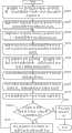
参阅图3所示,是本发明可疑目标识别及追踪方法较佳实施例的流程图。Referring to FIG. 3 , it is a flow chart of a preferred embodiment of the suspicious target identification and tracking method of the present invention.
步骤S101,接收模块110接收摄像头40采集的监控区域的一张视频图像(例如t=1s时刻的一张视频图像),选择模块120在该视频图像中选择一个运动的人物作为追踪目标。Step S101 , the receiving
步骤S103,目标追踪模块130根据可疑目标追踪演算法确定该追踪目标在该视频图像中的位置p1(x1,y1,z1)。在本实施例中,该可疑目标追踪演算法为连续自适应平均值迁移算法(ContinuouslyApative Mean-Shift,CamShift)。该算法根据追踪目标的颜色特征在视频图像中搜索追踪目标,确定追踪目标在视频图像中的位置和大小。例如,在本实施例中,假设追踪目标着装的主要颜色为深红色,则目标追踪模块130以包含所述深红色范围的最小矩形为追踪目标在t=s1时刻视频图像中的大小,以该最小矩形的中心点的位置为追踪目标在t=s1时刻视频图像中的位置p1(x1,y1,z1)。In step S103 , the
步骤S105,目标追踪模块130根据可疑目标追踪演算法确定该追踪目标在下一张视频图像(例如t=2s时刻的一张视频图像)中的位置p2(x2,y2,z2)。具体方法与步骤S103类似,在此不再赘述。Step S105 , the
步骤S107,目标追踪模块130根据该追踪目标在该两张视频图像中的位置计算该追踪目标在监控区域的移动方向及移动距离。例如,目标追踪模块130计算p2(x2,y2,z2)与p1(x1,y1,z1)的差值,得到该追踪目标在t=1s至t=2s时间内在监控区域的移动方向及移动距离。Step S107 , the
步骤S109,命令生成模块140根据上述计算结果产生控制命令,并发送该控制命令至云台控制器20,云台控制器20根据该控制命令控制摄像头40向相应方向移动相应距离,使得该追踪目标始终处于摄像头40的视角范围内。例如,云台控制器20根据该控制命令控制摄像头40向X轴方向移动(x2-x1)的距离,Y轴方向移动(y2-y1)的距离,Z轴方向移动(z2-z1)的距离。Step S109, the
步骤S111,云台控制器20驱动红外发光二极管30产生红外线照射该追踪目标。Step S111 , the pan/
步骤S113,红外光电管50感测红外线穿透追踪目标后的光强度变化,根据光强度变化产生脉冲电信号,并通过信号线将该脉冲电信号传送给云台控制器20。Step S113 , the
步骤S115,云台控制器20将该脉冲电信号转换为数字信号,并通过信号线将该数字信号发送给计算机10。Step S115 , the pan/
步骤S117,判断模块150判断该数字信号的频率是否超过人的正常心跳频率范围,例如60~100次/每分钟。若该数字信号的频率超过人的正常心跳频率范围,则流程进入步骤S119。若该数字信号的频率未超过人的正常心跳频率范围,则流程进入步骤S121。In step S117, the judging
步骤S119,判断模块150认定该追踪目标为可疑目标,报警模块160开启计算机的报警装置,例如LED警示灯,以通知监控人员监控区域有可疑目标出现。之后,流程自步骤S105开始重复,以继续追踪该追踪目标。In step S119, the judging
步骤S121,目标追踪模块130停止追踪该追踪目标。之后,流程结束。In step S121, the
最后应说明的是,以上实施例仅用以说明本发明的技术方案而非限制,尽管参照较佳实施例对本发明进行了详细说明,本领域的普通技术人员应当理解,可以对本发明的技术方案进行修改或等同替换,而不脱离本发明技术方案的精神和范围。Finally, it should be noted that the above embodiments are only used to illustrate the technical solutions of the present invention without limitation. Although the present invention has been described in detail with reference to the preferred embodiments, those of ordinary skill in the art should understand that the technical solutions of the present invention can be Modifications or equivalent replacements can be made without departing from the spirit and scope of the technical solutions of the present invention.
Claims (10)
Translated fromChinesePriority Applications (3)
| Application Number | Priority Date | Filing Date | Title |
|---|---|---|---|
| CN2010105234074ACN102457712A (en) | 2010-10-28 | 2010-10-28 | System and method for identifying and tracking suspicious target |
| US13/115,076US20120105630A1 (en) | 2010-10-28 | 2011-05-24 | Electronic device and method for recognizing and tracking suspects |
| JP2011224741AJP2012095292A (en) | 2010-10-28 | 2011-10-12 | System for identifying and tracking suspects and method therefor |
Applications Claiming Priority (1)
| Application Number | Priority Date | Filing Date | Title |
|---|---|---|---|
| CN2010105234074ACN102457712A (en) | 2010-10-28 | 2010-10-28 | System and method for identifying and tracking suspicious target |
Publications (1)
| Publication Number | Publication Date |
|---|---|
| CN102457712Atrue CN102457712A (en) | 2012-05-16 |
Family
ID=45996284
Family Applications (1)
| Application Number | Title | Priority Date | Filing Date |
|---|---|---|---|
| CN2010105234074APendingCN102457712A (en) | 2010-10-28 | 2010-10-28 | System and method for identifying and tracking suspicious target |
Country Status (3)
| Country | Link |
|---|---|
| US (1) | US20120105630A1 (en) |
| JP (1) | JP2012095292A (en) |
| CN (1) | CN102457712A (en) |
Cited By (19)
| Publication number | Priority date | Publication date | Assignee | Title |
|---|---|---|---|---|
| CN103634509A (en)* | 2012-08-30 | 2014-03-12 | 苏州翔合智能科技有限公司 | Automatic tracking recording method and system |
| CN103679197A (en)* | 2013-12-09 | 2014-03-26 | 华为技术有限公司 | Remote help seeking method, terminal device and remote help seeking system |
| CN105354956A (en)* | 2015-11-10 | 2016-02-24 | 成都智慧数联信息技术有限公司 | Cloud calculation and method based on data mining and large data analysis |
| CN105427518A (en)* | 2015-11-10 | 2016-03-23 | 成都智慧数联信息技术有限公司 | Digitalized risk decision system and method |
| CN106331890A (en)* | 2015-06-24 | 2017-01-11 | 中兴通讯股份有限公司 | Processing method and device for video communication image |
| CN106534682A (en)* | 2016-11-10 | 2017-03-22 | 上海大学 | Portable monitoring alarm device |
| CN107277345A (en)* | 2013-01-17 | 2017-10-20 | 佳能株式会社 | Camera device and its control method, remote control and its control method |
| CN108401140A (en)* | 2018-04-07 | 2018-08-14 | 深圳供电局有限公司 | Intelligent video monitoring system and method based on multilayer visual processing |
| CN108810505A (en)* | 2018-06-06 | 2018-11-13 | 合肥康之恒机械科技有限公司 | A kind of dynamic object efficiently tracks the data-optimized transmission method of image and system |
| CN108806146A (en)* | 2018-06-06 | 2018-11-13 | 合肥嘉仕诚能源科技有限公司 | A kind of safety monitoring dynamic object track lock method and system |
| CN108876848A (en)* | 2017-05-12 | 2018-11-23 | 宏达国际电子股份有限公司 | tracking system and tracking method thereof |
| CN109696926A (en)* | 2019-02-26 | 2019-04-30 | 穆树亮 | A kind of mobile object tracking irradiation unit of band time projection function |
| CN111537884A (en)* | 2020-04-17 | 2020-08-14 | 中国科学院深圳先进技术研究院 | Method and device for acquiring service life data of power battery, computer equipment and medium |
| CN111750736A (en)* | 2020-07-24 | 2020-10-09 | 陈喜春 | Method for identifying tracking target and laser countermeasure device |
| CN112668436A (en)* | 2020-12-23 | 2021-04-16 | 广州辰创科技发展有限公司 | Method, equipment and storage medium for tracking key control articles based on video analysis |
| CN113179387A (en)* | 2021-03-31 | 2021-07-27 | 深圳市紫光照明技术股份有限公司 | Intelligent monitoring system and method |
| CN114827464A (en)* | 2022-04-19 | 2022-07-29 | 北京拙河科技有限公司 | Target tracking method and system based on mobile camera |
| CN115225852A (en)* | 2021-04-21 | 2022-10-21 | 中国石油天然气股份有限公司 | Oil and gas pipeline monitoring method, monitoring component and computer storage medium |
| CN116503814A (en)* | 2023-05-24 | 2023-07-28 | 北京安录国际技术有限公司 | Personnel tracking method and system for analysis |
Families Citing this family (19)
| Publication number | Priority date | Publication date | Assignee | Title |
|---|---|---|---|---|
| CN103945234A (en)* | 2014-03-27 | 2014-07-23 | 百度在线网络技术(北京)有限公司 | Video-related information providing method and device |
| DE102014220042B4 (en)* | 2014-10-02 | 2018-01-04 | Volkswagen Ag | Access system for a vehicle |
| JP6310093B2 (en)* | 2014-11-12 | 2018-04-11 | エスゼット ディージェイアイ テクノロジー カンパニー リミテッドSz Dji Technology Co.,Ltd | Target object detection method, detection apparatus, and robot |
| EP3273672B1 (en)* | 2015-03-17 | 2020-12-30 | Nec Corporation | Monitoring device, monitoring method, monitoring program, and monitoring system |
| CN104777778A (en)* | 2015-04-19 | 2015-07-15 | 苏州市博群生物科技有限公司 | Monitoring system based on retina recognition and password confirmation |
| CN104751587A (en)* | 2015-04-19 | 2015-07-01 | 苏州市博群生物科技有限公司 | Safety monitoring system based on internet of things and retina recognition |
| CN104767820A (en)* | 2015-04-19 | 2015-07-08 | 苏州市博群生物科技有限公司 | Safety monitoring system based on Internet of Things and fingerprint recognition |
| JP6642568B2 (en)* | 2015-04-20 | 2020-02-05 | 日本電気株式会社 | Target identification system, target identification method and program |
| CN105120225A (en)* | 2015-09-10 | 2015-12-02 | 深圳市格视智能科技有限公司 | Intelligent visible behavioral intervention cradle head system |
| CN105450996A (en)* | 2015-12-07 | 2016-03-30 | 成都比善科技开发有限公司 | Intelligent cat eye system for automatically starting doorbell call |
| CN105430346B (en)* | 2015-12-07 | 2019-04-09 | 成都比善科技开发有限公司 | Multifunctional intellectual opal system |
| CN105306912B (en)* | 2015-12-07 | 2018-06-26 | 成都比善科技开发有限公司 | Intelligent peephole system based on luminous intensity and apart from detection triggering camera shooting |
| CN105516559A (en)* | 2015-12-07 | 2016-04-20 | 成都比善科技开发有限公司 | Multifunctional smart cat-eye system capable of adaptively rotating lens |
| US10701244B2 (en)* | 2016-09-30 | 2020-06-30 | Microsoft Technology Licensing, Llc | Recolorization of infrared image streams |
| CN106791643A (en)* | 2016-12-16 | 2017-05-31 | 合肥寰景信息技术有限公司 | A kind of traffic lights analysis detecting system based on video analysis |
| EP3340104B1 (en) | 2016-12-21 | 2023-11-29 | Axis AB | A method for generating alerts in a video surveillance system |
| WO2018156970A1 (en)* | 2017-02-24 | 2018-08-30 | Flir Systems, Inc. | Real-time detection of periodic motion systems and methods |
| CN111867206A (en)* | 2019-04-24 | 2020-10-30 | 厦门赢科光电有限公司 | Lighting device control method and system and terminal equipment |
| US12380487B2 (en) | 2022-03-15 | 2025-08-05 | Toshiba Global Commerce Solutions Holdings Corporation | Method, system, and non-transitory computer readable medium for frictionless shopping using emitted light signals |
Citations (5)
| Publication number | Priority date | Publication date | Assignee | Title |
|---|---|---|---|---|
| US4100536A (en)* | 1976-10-07 | 1978-07-11 | Thomas S. Ball | Bio-alarm security system |
| CN1447130A (en)* | 2003-03-21 | 2003-10-08 | 孔鹏 | Infrared self direction system |
| US20040193063A1 (en)* | 2003-02-28 | 2004-09-30 | Teiyuu Kimura | Method and apparatus for measuring biological condition |
| US20050128291A1 (en)* | 2002-04-17 | 2005-06-16 | Yoshishige Murakami | Video surveillance system |
| US20060129276A1 (en)* | 2004-12-14 | 2006-06-15 | Honda Motor Co., Ltd. | Autonomous mobile robot |
Family Cites Families (3)
| Publication number | Priority date | Publication date | Assignee | Title |
|---|---|---|---|---|
| US6363160B1 (en)* | 1999-01-22 | 2002-03-26 | Intel Corporation | Interface using pattern recognition and tracking |
| US7542592B2 (en)* | 2004-03-29 | 2009-06-02 | Siemesn Corporate Research, Inc. | Systems and methods for face detection and recognition using infrared imaging |
| US7346378B2 (en)* | 2005-05-02 | 2008-03-18 | Pronk Technologies Inc. | Light transmission simulator for pulse oximeter |
- 2010
- 2010-10-28CNCN2010105234074Apatent/CN102457712A/enactivePending
- 2011
- 2011-05-24USUS13/115,076patent/US20120105630A1/ennot_activeAbandoned
- 2011-10-12JPJP2011224741Apatent/JP2012095292A/enactivePending
Patent Citations (5)
| Publication number | Priority date | Publication date | Assignee | Title |
|---|---|---|---|---|
| US4100536A (en)* | 1976-10-07 | 1978-07-11 | Thomas S. Ball | Bio-alarm security system |
| US20050128291A1 (en)* | 2002-04-17 | 2005-06-16 | Yoshishige Murakami | Video surveillance system |
| US20040193063A1 (en)* | 2003-02-28 | 2004-09-30 | Teiyuu Kimura | Method and apparatus for measuring biological condition |
| CN1447130A (en)* | 2003-03-21 | 2003-10-08 | 孔鹏 | Infrared self direction system |
| US20060129276A1 (en)* | 2004-12-14 | 2006-06-15 | Honda Motor Co., Ltd. | Autonomous mobile robot |
Cited By (26)
| Publication number | Priority date | Publication date | Assignee | Title |
|---|---|---|---|---|
| CN103634509A (en)* | 2012-08-30 | 2014-03-12 | 苏州翔合智能科技有限公司 | Automatic tracking recording method and system |
| CN107277345A (en)* | 2013-01-17 | 2017-10-20 | 佳能株式会社 | Camera device and its control method, remote control and its control method |
| CN107277345B (en)* | 2013-01-17 | 2020-12-01 | 佳能株式会社 | Image pickup apparatus, control method thereof, remote control apparatus, and control method thereof |
| CN103679197A (en)* | 2013-12-09 | 2014-03-26 | 华为技术有限公司 | Remote help seeking method, terminal device and remote help seeking system |
| CN106331890A (en)* | 2015-06-24 | 2017-01-11 | 中兴通讯股份有限公司 | Processing method and device for video communication image |
| CN105354956A (en)* | 2015-11-10 | 2016-02-24 | 成都智慧数联信息技术有限公司 | Cloud calculation and method based on data mining and large data analysis |
| CN105427518A (en)* | 2015-11-10 | 2016-03-23 | 成都智慧数联信息技术有限公司 | Digitalized risk decision system and method |
| CN105354956B (en)* | 2015-11-10 | 2017-06-23 | 成都智慧数联信息技术有限公司 | The cloud computing platform and method analyzed based on data mining and big data |
| CN105427518B (en)* | 2015-11-10 | 2017-08-01 | 成都智慧数联信息技术有限公司 | A kind of dangerous decision system of digitization and method |
| CN106534682A (en)* | 2016-11-10 | 2017-03-22 | 上海大学 | Portable monitoring alarm device |
| CN108876848A (en)* | 2017-05-12 | 2018-11-23 | 宏达国际电子股份有限公司 | tracking system and tracking method thereof |
| CN108401140A (en)* | 2018-04-07 | 2018-08-14 | 深圳供电局有限公司 | Intelligent video monitoring system and method based on multilayer visual processing |
| CN108810505A (en)* | 2018-06-06 | 2018-11-13 | 合肥康之恒机械科技有限公司 | A kind of dynamic object efficiently tracks the data-optimized transmission method of image and system |
| CN108806146A (en)* | 2018-06-06 | 2018-11-13 | 合肥嘉仕诚能源科技有限公司 | A kind of safety monitoring dynamic object track lock method and system |
| CN109696926A (en)* | 2019-02-26 | 2019-04-30 | 穆树亮 | A kind of mobile object tracking irradiation unit of band time projection function |
| CN111537884B (en)* | 2020-04-17 | 2022-04-29 | 中国科学院深圳先进技术研究院 | Method, device, computer equipment and medium for obtaining power battery life data |
| CN111537884A (en)* | 2020-04-17 | 2020-08-14 | 中国科学院深圳先进技术研究院 | Method and device for acquiring service life data of power battery, computer equipment and medium |
| CN111750736A (en)* | 2020-07-24 | 2020-10-09 | 陈喜春 | Method for identifying tracking target and laser countermeasure device |
| CN112668436A (en)* | 2020-12-23 | 2021-04-16 | 广州辰创科技发展有限公司 | Method, equipment and storage medium for tracking key control articles based on video analysis |
| CN113179387A (en)* | 2021-03-31 | 2021-07-27 | 深圳市紫光照明技术股份有限公司 | Intelligent monitoring system and method |
| CN113179387B (en)* | 2021-03-31 | 2022-07-26 | 深圳市紫光照明技术股份有限公司 | Intelligent monitoring system and method |
| CN115225852A (en)* | 2021-04-21 | 2022-10-21 | 中国石油天然气股份有限公司 | Oil and gas pipeline monitoring method, monitoring component and computer storage medium |
| CN114827464A (en)* | 2022-04-19 | 2022-07-29 | 北京拙河科技有限公司 | Target tracking method and system based on mobile camera |
| CN114827464B (en)* | 2022-04-19 | 2023-03-03 | 北京拙河科技有限公司 | Target tracking method and system based on mobile camera |
| CN116503814A (en)* | 2023-05-24 | 2023-07-28 | 北京安录国际技术有限公司 | Personnel tracking method and system for analysis |
| CN116503814B (en)* | 2023-05-24 | 2023-10-24 | 北京安录国际技术有限公司 | Personnel tracking method and system for analysis |
Also Published As
| Publication number | Publication date |
|---|---|
| JP2012095292A (en) | 2012-05-17 |
| US20120105630A1 (en) | 2012-05-03 |
Similar Documents
| Publication | Publication Date | Title |
|---|---|---|
| CN102457712A (en) | System and method for identifying and tracking suspicious target | |
| US8427324B2 (en) | Method and system for detecting a fallen person using a range imaging device | |
| US20130338525A1 (en) | Mobile Human Interface Robot | |
| US9002511B1 (en) | Methods and systems for obstacle detection using structured light | |
| JP5963372B2 (en) | How to make a mobile robot follow people | |
| US6801637B2 (en) | Optical body tracker | |
| EP3192330B1 (en) | Lighting preference arbitration. | |
| US20090198374A1 (en) | Nursing system | |
| US8918209B2 (en) | Mobile human interface robot | |
| US9055226B2 (en) | System and method for controlling fixtures based on tracking data | |
| KR101593187B1 (en) | Device and method surveiling innormal behavior using 3d image information | |
| JP2018018829A (en) | Sensing lighting system and method for characterizing an illumination space | |
| WO2011146259A2 (en) | Mobile human interface robot | |
| US11967183B2 (en) | Notification system and notification device | |
| Hunter et al. | Visible light communication using a digital camera and an LED flashlight | |
| CN108802762A (en) | A kind of obstacle avoidance apparatus and barrier-avoiding method of Intelligent luggage carrier | |
| Naser et al. | Shadowcam: Real-time detection of moving obstacles behind a corner for autonomous vehicles | |
| CN111736596A (en) | Vehicle with gesture control function, gesture control method of vehicle, and storage medium | |
| WO2012002904A1 (en) | Device and method for detection of abnormal spatial states of a human body | |
| TW201220215A (en) | Suspicious object recognizing and tracking system and method | |
| JP4448249B2 (en) | Image recognition device | |
| JP6129475B2 (en) | Monitoring device and monitoring method | |
| CN212781269U (en) | An anti-trailing detection system for self-service inspection channels based on human body induction | |
| JP2024521918A (en) | System and method for determining occupant configuration in a space using sensors having single pixel thermopiles - Patents.com | |
| WO2024203895A1 (en) | Monitoring device and monitoring system |
Legal Events
| Date | Code | Title | Description |
|---|---|---|---|
| C06 | Publication | ||
| PB01 | Publication | ||
| C10 | Entry into substantive examination | ||
| SE01 | Entry into force of request for substantive examination | ||
| C41 | Transfer of patent application or patent right or utility model | ||
| TA01 | Transfer of patent application right | Effective date of registration:20151026 Address after:518109 Guangdong province Shenzhen city Longhua District Dragon Road No. 83 wing group building 11 floor Applicant after:SCIENBIZIP CONSULTING (SHEN ZHEN) CO., LTD. Address before:518109 Guangdong city of Shenzhen province Baoan District Longhua Town Industrial Zone tabulaeformis tenth East Ring Road No. 2 two Applicant before:Hongfujin Precise Industry (Shenzhen) Co., Ltd. Applicant before:Hon Hai Precision Industry Co., Ltd. | |
| C02 | Deemed withdrawal of patent application after publication (patent law 2001) | ||
| WD01 | Invention patent application deemed withdrawn after publication | Application publication date:20120516 |