CN102449841A - Passivation film for solid electrolyte interface of three dimensional copper containing electrode in energy storage device - Google Patents
Passivation film for solid electrolyte interface of three dimensional copper containing electrode in energy storage deviceDownload PDFInfo
- Publication number
- CN102449841A CN102449841ACN2010800250647ACN201080025064ACN102449841ACN 102449841 ACN102449841 ACN 102449841ACN 2010800250647 ACN2010800250647 ACN 2010800250647ACN 201080025064 ACN201080025064 ACN 201080025064ACN 102449841 ACN102449841 ACN 102449841A
- Authority
- CN
- China
- Prior art keywords
- copper
- chamber
- lithium
- oxide
- cobalt
- Prior art date
- Legal status (The legal status is an assumption and is not a legal conclusion. Google has not performed a legal analysis and makes no representation as to the accuracy of the status listed.)
- Pending
Links
Images


Classifications
- H—ELECTRICITY
- H01—ELECTRIC ELEMENTS
- H01M—PROCESSES OR MEANS, e.g. BATTERIES, FOR THE DIRECT CONVERSION OF CHEMICAL ENERGY INTO ELECTRICAL ENERGY
- H01M4/00—Electrodes
- H01M4/02—Electrodes composed of, or comprising, active material
- H01M4/04—Processes of manufacture in general
- H01M4/0438—Processes of manufacture in general by electrochemical processing
- H—ELECTRICITY
- H01—ELECTRIC ELEMENTS
- H01M—PROCESSES OR MEANS, e.g. BATTERIES, FOR THE DIRECT CONVERSION OF CHEMICAL ENERGY INTO ELECTRICAL ENERGY
- H01M4/00—Electrodes
- H01M4/02—Electrodes composed of, or comprising, active material
- H01M4/64—Carriers or collectors
- H01M4/66—Selection of materials
- C—CHEMISTRY; METALLURGY
- C25—ELECTROLYTIC OR ELECTROPHORETIC PROCESSES; APPARATUS THEREFOR
- C25D—PROCESSES FOR THE ELECTROLYTIC OR ELECTROPHORETIC PRODUCTION OF COATINGS; ELECTROFORMING; APPARATUS THEREFOR
- C25D17/00—Constructional parts, or assemblies thereof, of cells for electrolytic coating
- C—CHEMISTRY; METALLURGY
- C25—ELECTROLYTIC OR ELECTROPHORETIC PROCESSES; APPARATUS THEREFOR
- C25D—PROCESSES FOR THE ELECTROLYTIC OR ELECTROPHORETIC PRODUCTION OF COATINGS; ELECTROFORMING; APPARATUS THEREFOR
- C25D3/00—Electroplating: Baths therefor
- C25D3/02—Electroplating: Baths therefor from solutions
- C25D3/38—Electroplating: Baths therefor from solutions of copper
- C—CHEMISTRY; METALLURGY
- C25—ELECTROLYTIC OR ELECTROPHORETIC PROCESSES; APPARATUS THEREFOR
- C25D—PROCESSES FOR THE ELECTROLYTIC OR ELECTROPHORETIC PRODUCTION OF COATINGS; ELECTROFORMING; APPARATUS THEREFOR
- C25D7/00—Electroplating characterised by the article coated
- C25D7/06—Wires; Strips; Foils
- C25D7/0614—Strips or foils
- H—ELECTRICITY
- H01—ELECTRIC ELEMENTS
- H01B—CABLES; CONDUCTORS; INSULATORS; SELECTION OF MATERIALS FOR THEIR CONDUCTIVE, INSULATING OR DIELECTRIC PROPERTIES
- H01B1/00—Conductors or conductive bodies characterised by the conductive materials; Selection of materials as conductors
- H01B1/02—Conductors or conductive bodies characterised by the conductive materials; Selection of materials as conductors mainly consisting of metals or alloys
- H—ELECTRICITY
- H01—ELECTRIC ELEMENTS
- H01G—CAPACITORS; CAPACITORS, RECTIFIERS, DETECTORS, SWITCHING DEVICES, LIGHT-SENSITIVE OR TEMPERATURE-SENSITIVE DEVICES OF THE ELECTROLYTIC TYPE
- H01G9/00—Electrolytic capacitors, rectifiers, detectors, switching devices, light-sensitive or temperature-sensitive devices; Processes of their manufacture
- H01G9/004—Details
- H01G9/04—Electrodes or formation of dielectric layers thereon
- H—ELECTRICITY
- H01—ELECTRIC ELEMENTS
- H01M—PROCESSES OR MEANS, e.g. BATTERIES, FOR THE DIRECT CONVERSION OF CHEMICAL ENERGY INTO ELECTRICAL ENERGY
- H01M4/00—Electrodes
- H01M4/02—Electrodes composed of, or comprising, active material
- H01M4/04—Processes of manufacture in general
- H01M4/0438—Processes of manufacture in general by electrochemical processing
- H01M4/045—Electrochemical coating; Electrochemical impregnation
- H01M4/0452—Electrochemical coating; Electrochemical impregnation from solutions
- H—ELECTRICITY
- H01—ELECTRIC ELEMENTS
- H01M—PROCESSES OR MEANS, e.g. BATTERIES, FOR THE DIRECT CONVERSION OF CHEMICAL ENERGY INTO ELECTRICAL ENERGY
- H01M4/00—Electrodes
- H01M4/02—Electrodes composed of, or comprising, active material
- H01M4/13—Electrodes for accumulators with non-aqueous electrolyte, e.g. for lithium-accumulators; Processes of manufacture thereof
- H01M4/133—Electrodes based on carbonaceous material, e.g. graphite-intercalation compounds or CFx
- H—ELECTRICITY
- H01—ELECTRIC ELEMENTS
- H01M—PROCESSES OR MEANS, e.g. BATTERIES, FOR THE DIRECT CONVERSION OF CHEMICAL ENERGY INTO ELECTRICAL ENERGY
- H01M4/00—Electrodes
- H01M4/02—Electrodes composed of, or comprising, active material
- H01M4/13—Electrodes for accumulators with non-aqueous electrolyte, e.g. for lithium-accumulators; Processes of manufacture thereof
- H01M4/139—Processes of manufacture
- H01M4/1393—Processes of manufacture of electrodes based on carbonaceous material, e.g. graphite-intercalation compounds or CFx
- H—ELECTRICITY
- H01—ELECTRIC ELEMENTS
- H01M—PROCESSES OR MEANS, e.g. BATTERIES, FOR THE DIRECT CONVERSION OF CHEMICAL ENERGY INTO ELECTRICAL ENERGY
- H01M4/00—Electrodes
- H01M4/02—Electrodes composed of, or comprising, active material
- H01M4/62—Selection of inactive substances as ingredients for active masses, e.g. binders, fillers
- H—ELECTRICITY
- H01—ELECTRIC ELEMENTS
- H01M—PROCESSES OR MEANS, e.g. BATTERIES, FOR THE DIRECT CONVERSION OF CHEMICAL ENERGY INTO ELECTRICAL ENERGY
- H01M4/00—Electrodes
- H01M4/02—Electrodes composed of, or comprising, active material
- H01M4/64—Carriers or collectors
- H01M4/66—Selection of materials
- H01M4/661—Metal or alloys, e.g. alloy coatings
- H—ELECTRICITY
- H01—ELECTRIC ELEMENTS
- H01M—PROCESSES OR MEANS, e.g. BATTERIES, FOR THE DIRECT CONVERSION OF CHEMICAL ENERGY INTO ELECTRICAL ENERGY
- H01M4/00—Electrodes
- H01M4/02—Electrodes composed of, or comprising, active material
- H01M4/64—Carriers or collectors
- H01M4/66—Selection of materials
- H01M4/664—Ceramic materials
- H—ELECTRICITY
- H01—ELECTRIC ELEMENTS
- H01M—PROCESSES OR MEANS, e.g. BATTERIES, FOR THE DIRECT CONVERSION OF CHEMICAL ENERGY INTO ELECTRICAL ENERGY
- H01M4/00—Electrodes
- H01M4/02—Electrodes composed of, or comprising, active material
- H01M4/64—Carriers or collectors
- H01M4/66—Selection of materials
- H01M4/665—Composites
- H01M4/667—Composites in the form of layers, e.g. coatings
- H—ELECTRICITY
- H01—ELECTRIC ELEMENTS
- H01M—PROCESSES OR MEANS, e.g. BATTERIES, FOR THE DIRECT CONVERSION OF CHEMICAL ENERGY INTO ELECTRICAL ENERGY
- H01M50/00—Constructional details or processes of manufacture of the non-active parts of electrochemical cells other than fuel cells, e.g. hybrid cells
- H01M50/40—Separators; Membranes; Diaphragms; Spacing elements inside cells
- H01M50/409—Separators, membranes or diaphragms characterised by the material
- H01M50/411—Organic material
- H—ELECTRICITY
- H01—ELECTRIC ELEMENTS
- H01M—PROCESSES OR MEANS, e.g. BATTERIES, FOR THE DIRECT CONVERSION OF CHEMICAL ENERGY INTO ELECTRICAL ENERGY
- H01M50/00—Constructional details or processes of manufacture of the non-active parts of electrochemical cells other than fuel cells, e.g. hybrid cells
- H01M50/40—Separators; Membranes; Diaphragms; Spacing elements inside cells
- H01M50/46—Separators, membranes or diaphragms characterised by their combination with electrodes
- H—ELECTRICITY
- H01—ELECTRIC ELEMENTS
- H01M—PROCESSES OR MEANS, e.g. BATTERIES, FOR THE DIRECT CONVERSION OF CHEMICAL ENERGY INTO ELECTRICAL ENERGY
- H01M50/00—Constructional details or processes of manufacture of the non-active parts of electrochemical cells other than fuel cells, e.g. hybrid cells
- H01M50/40—Separators; Membranes; Diaphragms; Spacing elements inside cells
- H01M50/409—Separators, membranes or diaphragms characterised by the material
- H01M50/411—Organic material
- H01M50/414—Synthetic resins, e.g. thermoplastics or thermosetting resins
- H01M50/417—Polyolefins
- Y—GENERAL TAGGING OF NEW TECHNOLOGICAL DEVELOPMENTS; GENERAL TAGGING OF CROSS-SECTIONAL TECHNOLOGIES SPANNING OVER SEVERAL SECTIONS OF THE IPC; TECHNICAL SUBJECTS COVERED BY FORMER USPC CROSS-REFERENCE ART COLLECTIONS [XRACs] AND DIGESTS
- Y02—TECHNOLOGIES OR APPLICATIONS FOR MITIGATION OR ADAPTATION AGAINST CLIMATE CHANGE
- Y02E—REDUCTION OF GREENHOUSE GAS [GHG] EMISSIONS, RELATED TO ENERGY GENERATION, TRANSMISSION OR DISTRIBUTION
- Y02E60/00—Enabling technologies; Technologies with a potential or indirect contribution to GHG emissions mitigation
- Y02E60/10—Energy storage using batteries
- Y—GENERAL TAGGING OF NEW TECHNOLOGICAL DEVELOPMENTS; GENERAL TAGGING OF CROSS-SECTIONAL TECHNOLOGIES SPANNING OVER SEVERAL SECTIONS OF THE IPC; TECHNICAL SUBJECTS COVERED BY FORMER USPC CROSS-REFERENCE ART COLLECTIONS [XRACs] AND DIGESTS
- Y02—TECHNOLOGIES OR APPLICATIONS FOR MITIGATION OR ADAPTATION AGAINST CLIMATE CHANGE
- Y02E—REDUCTION OF GREENHOUSE GAS [GHG] EMISSIONS, RELATED TO ENERGY GENERATION, TRANSMISSION OR DISTRIBUTION
- Y02E60/00—Enabling technologies; Technologies with a potential or indirect contribution to GHG emissions mitigation
- Y02E60/13—Energy storage using capacitors
- Y—GENERAL TAGGING OF NEW TECHNOLOGICAL DEVELOPMENTS; GENERAL TAGGING OF CROSS-SECTIONAL TECHNOLOGIES SPANNING OVER SEVERAL SECTIONS OF THE IPC; TECHNICAL SUBJECTS COVERED BY FORMER USPC CROSS-REFERENCE ART COLLECTIONS [XRACs] AND DIGESTS
- Y02—TECHNOLOGIES OR APPLICATIONS FOR MITIGATION OR ADAPTATION AGAINST CLIMATE CHANGE
- Y02P—CLIMATE CHANGE MITIGATION TECHNOLOGIES IN THE PRODUCTION OR PROCESSING OF GOODS
- Y02P20/00—Technologies relating to chemical industry
- Y02P20/10—Process efficiency
- Y02P20/133—Renewable energy sources, e.g. sunlight
Landscapes
- Chemical & Material Sciences (AREA)
- Engineering & Computer Science (AREA)
- Chemical Kinetics & Catalysis (AREA)
- Electrochemistry (AREA)
- General Chemical & Material Sciences (AREA)
- Materials Engineering (AREA)
- Manufacturing & Machinery (AREA)
- Organic Chemistry (AREA)
- Metallurgy (AREA)
- Composite Materials (AREA)
- Ceramic Engineering (AREA)
- Power Engineering (AREA)
- Microelectronics & Electronic Packaging (AREA)
- Battery Electrode And Active Subsutance (AREA)
- Secondary Cells (AREA)
- Cell Electrode Carriers And Collectors (AREA)
- Cell Separators (AREA)
Abstract
Translated fromChinese
Description
Translated fromChinese背景background
技术领域technical field
本发明实施例大致关于锂-离子电池,更明确地关于利用形成三维结构的薄膜沉积处理制造上述电池的系统与方法。Embodiments of the present invention relate generally to lithium-ion batteries, and more specifically to systems and methods for fabricating such batteries using thin film deposition processes that form three-dimensional structures.
相关技术描述Related technical description
快速充电、高容量的能量储存装置(诸如,超级电容器与锂-离子(Li+)电池)用于越来越多种应用中,应用包括便携式电子、医疗、运输、并网型大能量储存器、可再生能量储存器与不间断电源供应器(UPS)。在现代可充电能量储存装置中,集电器由导电体所制成。用于正集电器(阴极)的材料实例包括铝、不锈钢与镍。用于负集电器(阳极)的材料实例包括铜(Cu)、不锈钢与镍(Ni)。上述集电器形状可为箔、膜或薄板,其厚度通常在约6至50μm之间。Fast-charging, high-capacity energy storage devices such as supercapacitors and lithium-ion (Li+ ) batteries are used in a growing variety of applications including portable electronics, medical, transportation, grid-connected large energy storage , Renewable energy storage and uninterruptible power supply (UPS). In modern rechargeable energy storage devices, the current collectors are made of electrical conductors. Examples of materials for the positive current collector (cathode) include aluminum, stainless steel, and nickel. Examples of materials for the negative current collector (anode) include copper (Cu), stainless steel, and nickel (Ni). The above-mentioned current collector may be in the form of a foil, film or sheet, and its thickness is usually between about 6 and 50 μm.
Li-离子电池的正电极中的活性电极材料通常选自锂过渡金属氧化物(诸如,LiMn2O4、LiCoO2与/或LiNiO2),且包括导电微粒(诸如,碳或石墨)与接合材料。上述正电极材料被视为锂-嵌入化合物,其中导电材料的数量在重量百分比0.1%至15%之间。The active electrode material in the positive electrode of a Li-ion battery is usually selected from lithium transition metal oxides such as LiMn2 O4 , LiCoO2 and/or LiNiO2 , and includes conductive particles such as carbon or graphite and bonded Material. The aforementioned positive electrode materials are considered as lithium-intercalation compounds in which the amount of conductive material is between 0.1% and 15% by weight.
通常将石墨作为负电极的活性电极材料,且其形态可为锂-嵌入中间相碳微球(MCMB)粉末,所述粉末由直径约10μm的MCMB所构成。将锂-嵌入MCMB粉末分散于聚合接合物基质中。接合物基质的聚合物由热塑性聚合物(包括具有橡胶弹性的聚合物)所构成。聚合接合物用以将MCMB材料粉末接合在一起,以排除破裂形成并避免MCMB粉末在集电器表面上瓦解。聚合接合物的数量为重量百分比2%至30%之间。Graphite is generally used as the active electrode material of the negative electrode, and its form can be lithium-intercalated mesocarbon microsphere (MCMB) powder, which is composed of MCMB with a diameter of about 10 μm. Lithium-intercalated MCMB powder is dispersed in a polymeric conjugate matrix. The polymer of the binder matrix is composed of thermoplastic polymers, including rubber-elastic polymers. A polymeric binder is used to bond the MCMB material powder together to preclude crack formation and avoid disintegration of the MCMB powder on the current collector surface. The amount of polymer binder is between 2% and 30% by weight.
Li-离子电池的隔离器通常由微-多孔聚乙烯与聚烯烃所构成,且在单独的制造步骤中加以应用。Separators for Li-ion batteries are usually composed of micro-porous polyethylene and polyolefin and are applied in a separate manufacturing step.
对于大部分能量储存应用而言,能量储存装置的充电时间与容量系重要的参数。此外,上述能量储存装置的尺寸、重量和/或成本亦为重要的限制因素。For most energy storage applications, the charging time and capacity of the energy storage device are important parameters. In addition, the size, weight and/or cost of the aforementioned energy storage devices are also important limiting factors.
因此,本领域中需要更快速充电、更高容量、较小且较轻且可更具成本效应地加以制造的能量储存装置。Accordingly, there is a need in the art for energy storage devices that charge faster, have higher capacity, are smaller and lighter, and can be manufactured more cost-effectively.
发明内容Contents of the invention
本发明实施例大致关于锂-离子电池,且更明确地关于利用形成三维结构的薄膜沉积处理制造上述电池的系统与方法。在一个实施例中,提供用来形成能量储存装置的阳极结构。所述阳极结构包括导电基板、形成于基板上的多个导电微结构、形成于导电微结构上的钝化膜、以及形成于导电微结构上的绝缘分隔层,其中导电微结构包括柱状凸出部。Embodiments of the present invention relate generally to lithium-ion batteries, and more specifically to systems and methods for fabricating such batteries using thin film deposition processes that form three-dimensional structures. In one embodiment, an anode structure for forming an energy storage device is provided. The anode structure includes a conductive substrate, a plurality of conductive microstructures formed on the substrate, a passivation film formed on the conductive microstructures, and an insulating separation layer formed on the conductive microstructures, wherein the conductive microstructures include columnar protrusions department.
在另一实施例中,提供形成阳极结构的方法。该方法包括在导电基板上沉积多个导电微结构并在导电微结构上形成钝化膜。In another embodiment, a method of forming an anode structure is provided. The method includes depositing a plurality of conductive microstructures on a conductive substrate and forming a passivation film on the conductive microstructures.
在又一实施例中,提供处理挠性基板的基板处理系统。所述处理系统包括:第一镀覆腔室,所述第一镀覆腔室经配置以在挠性基板的一部分上镀覆包括第一导电材料的导电微结构;第一清洗腔室,所述第一清洗腔室邻近第一镀覆腔室而设置,所述第一清洗腔室经配置以利用清洗流体从挠性基板的所述部分上清洗且移除任何残余镀覆溶液;第二镀覆腔室,所述第二镀覆腔室邻近第一清洗腔室而设置,所述第二镀覆腔室经配置以在导电微结构上沉积第二导电材料;第二清洗腔室,第二清洗腔室邻近第二镀覆腔室而设置,所述第二清洗腔室经配置以从挠性基板的所述部分清洗且移除任何残余镀覆溶液;表面改性腔室,所述表面改性腔室经配置以在挠性基板的所述部分上形成钝化膜;基板传送机构,所述基板传送机构经配置以在腔室之间传送挠性基板,所述基板传送机构包括经配置以保留挠性基板的一部分的进料辊以及经配置以保留挠性基板的一部分的卷绕辊,其中基板传送机构经配置以激活进料辊与卷绕辊,以将挠性基板移动进出各个腔室,并将挠性基板固持在各个腔室的处理空间中。In yet another embodiment, a substrate processing system for processing flexible substrates is provided. The processing system includes: a first plating chamber configured to plate a conductive microstructure comprising a first conductive material on a portion of a flexible substrate; a first cleaning chamber, the the first cleaning chamber is disposed adjacent to the first plating chamber, the first cleaning chamber configured to clean and remove any residual plating solution from the portion of the flexible substrate with a cleaning fluid; the second a plating chamber, the second plating chamber disposed adjacent to the first cleaning chamber, the second plating chamber configured to deposit a second conductive material on the conductive microstructures; the second cleaning chamber, A second cleaning chamber is disposed adjacent to the second plating chamber, the second cleaning chamber configured to clean and remove any residual plating solution from the portion of the flexible substrate; the surface modification chamber, the The surface modification chamber configured to form a passivation film on the portion of the flexible substrate; a substrate transfer mechanism configured to transfer the flexible substrate between chambers, the substrate transfer mechanism including a feed roller configured to retain a portion of the flexible substrate and a take-up roller configured to retain a portion of the flexible substrate, wherein the substrate transport mechanism is configured to activate the feed roller and the take-up roller to place the flexible substrate Moving in and out of each chamber and holding the flexible substrate in the processing volume of each chamber.
在又一实施例中,提供制造电池单元的方法。所述方法包括:在基板的导电表面上形成导电微结构;在导电微结构上形成钝化膜;在钝化膜上沉积流体可穿透的电绝缘分隔层;在电绝缘分隔层上沉积活性阴极材料;利用薄膜金属沉积处理在活性阴极材料上沉积集电器;并在集电器上沉积介电层,其中导电微结构包括电镀处理形成的柱状凸出部。In yet another embodiment, a method of manufacturing a battery cell is provided. The method includes: forming a conductive microstructure on a conductive surface of a substrate; forming a passivation film on the conductive microstructure; depositing a fluid-permeable electrically insulating spacer layer on the passivation film; depositing an active active film on the electrically insulating spacer layer. a cathode material; depositing a current collector on the active cathode material using a thin film metal deposition process; and depositing a dielectric layer on the current collector, wherein the conductive microstructure includes columnar protrusions formed by the electroplating process.
在又一实施例中,提供制造电池单元的方法。所述方法包括藉由第一薄膜沉积处理形成阳极结构,第一薄膜沉积处理包括在第一基板的导电表面上形成导电微结构、在导电微结构上沉积钝化膜、在钝化膜上沉积流体可穿透的电绝缘分隔层、并在电绝缘分隔层上沉积活性阴极材料;藉由第二薄膜沉积处理形成阴极结构,第二薄膜沉积处理包括在基板的导电表面上形成导电微结构、在导电微结构上沉积活性阴极材料;并使阳极结构与阴极结构结合在一起。In yet another embodiment, a method of manufacturing a battery cell is provided. The method includes forming an anode structure by a first thin film deposition process comprising forming a conductive microstructure on a conductive surface of a first substrate, depositing a passivation film on the conductive microstructure, depositing a passivation film on the passivation film a fluid-permeable electrically insulating separator layer, and depositing an active cathode material on the electrically insulating separator layer; forming the cathode structure by a second thin film deposition process comprising forming conductive microstructures on the conductive surface of the substrate, depositing an active cathode material on the conductive microstructure; and bonding the anodic and cathodic structures together.
附图说明Description of drawings
因此,通过参照多个实施例可获得详细理解本发明的上述特征的方式以及以上概述的本发明的更具体描述,多个实施例中的一些在附图中示出。然而,需注意附图仅描绘本发明的典型实施例而因此不被视为对本发明范围的限制,因为本发明可允许其他等效实施例。Thus, the manner in which a detailed understanding of the above recited features of the invention, and a more particular description of the invention summarized above, may be had by reference to various embodiments, some of which are illustrated in the accompanying drawings. It is to be noted, however, that the appended drawings depict only typical embodiments of this invention and are therefore not to be considered limiting of its scope, for the invention may admit to other equally effective embodiments.
图1是根据本文所述实施例电耦接至负载的Li-离子电池的示意图;1 is a schematic diagram of a Li-ion battery electrically coupled to a load according to embodiments described herein;
图2A-2G是根据本文所述实施例形成的阳极结构的示意横剖面图;2A-2G are schematic cross-sectional views of anode structures formed according to embodiments described herein;
图3示意性描绘根据本文所述实施例的处理系统;Figure 3 schematically depicts a processing system according to embodiments described herein;
图4是概括根据本文所述实施例形成阳极结构的方法的处理流程图;4 is a process flow diagram outlining a method of forming an anode structure according to embodiments described herein;
图5是概括根据本文所述实施例形成阳极结构的方法的处理流程图;5 is a process flow diagram outlining a method of forming an anode structure according to embodiments described herein;
图6是概括根据本文所述实施例形成阳极结构的方法的处理流程图;以及6 is a process flow diagram outlining a method of forming an anode structure according to embodiments described herein; and
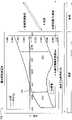
图7是证实根据本文所述实施例形成的钝化膜对能量储存装置的储存容量的影响的曲线图。7 is a graph demonstrating the effect of a passivation film formed according to embodiments described herein on the storage capacity of an energy storage device.
凸出部具体实施方式The specific embodiment of the protruding part
虽然可实践本文所述实施例的特定设备并未受限,但将所述实施例执行于Applied Materials,Inc.(Santa Clara,Calif.)所出售的网式辊-对-辊系统中是也别有利的。可执行本文所述实施例的示范性辊-对-辊和分立的基板系统描述于此,且进一步详细描述于共同受让的标题为“APPARATUS ANDMETHODS FOR FORMING ENERGY STORAGE OR PV DEVICES IN ALINEAR SYSTEM(用于在线性系统中形成能量储存或PV装置的设备和方法)”的美国专利临时申请61/243,813及Lopatin等人2009年11月18日申请且共同受让的标题为“APPARATUS AND METHOD FOR FORMING3D NANOSTRUCTURE ELECTRODE FOR ELECTROCHEMICALBATTERY AND CAPACITOR(用于形成电化学电池和电容器的3D纳米结构电极的设备和方法)”的美国专利申请12/620,788(公开案号为US2010-0126849),上述两篇专利文献的全文通过引用整体结合于此。其他处理腔室与系统(包括可从其他制造商取得的腔室与系统)亦可用来执行本文所述的实施例。一个示范性处理系统包括本文所述的辊-对-辊处理系统。While the particular equipment on which embodiments described herein may be practiced is not limited, the embodiments may also be implemented in a mesh roll-to-roll system sold by Applied Materials, Inc. (Santa Clara, Calif.). Do not benefit. Exemplary roll-to-roll and discrete substrate systems that may implement embodiments described herein are described herein, and are described in further detail in the commonly assigned application titled "APPARATUS ANDMETHODS FOR FORMING ENERGY STORAGE OR PV DEVICES IN ALINEAR SYSTEM (with APPARATUS AND METHOD FOR FORMING 3D NANOSTRUCTURE FOR APPARATUS AND METHOD FOR FORMING 3D NANOSTRUCTURE IN A LINEAR SYSTEM)" U.S. Patent Provisional Application 61/243,813 and Lopatin et al., filed November 18, 2009 and commonly assigned ELECTRODE FOR ELECTROCHEMICAL BATTERY AND CAPACITOR (apparatus and method for forming 3D nanostructured electrodes for electrochemical batteries and capacitors)" U.S. patent application 12/620,788 (published case number US2010-0126849), the full text of the above two patent documents is adopted This reference is hereby incorporated in its entirety. Other processing chambers and systems, including those available from other manufacturers, may also be used to perform the embodiments described herein. An exemplary handling system includes the roll-to-roll handling system described herein.
本文所述实施例构想利用薄膜沉积处理与其他形成电化学装置的方法来形成电化学装置(诸如,电池或超级电容器)。本文所述实施例包括在导电三维阳极结构上形成钝化膜。可通过电化学电镀处理、无电镀覆处理、化学气相沉积处理、物理气相沉积处理以及以上的组合来形成钝化膜。钝化膜有助于形成并维持固态电解质界面(SEI),且提供高容量及使用寿命长的电极。在一个实施例中,接着在钝化膜与导电三维阳极结构上形成多孔介电分隔层以形成能量储存装置的半-单元,诸如Li-离子电池的阳极结构或超级电容器的一半。在一个实施例中,分别形成电池的第二半-单元或超级电容器的一半并接着接合至分隔层。在另一实施例中,通过在分隔层上沉积额外的薄膜来形成电池的第二半单元或超级电容器的一半。Embodiments described herein contemplate forming electrochemical devices, such as batteries or supercapacitors, using thin film deposition processes and other methods of forming electrochemical devices. Embodiments described herein include forming a passivation film on a conductive three-dimensional anode structure. The passivation film may be formed by electrochemical plating treatment, electroless plating treatment, chemical vapor deposition treatment, physical vapor deposition treatment, and combinations thereof. The passivation film helps to form and maintain the solid electrolyte interface (SEI) and provides high capacity and long life electrodes. In one embodiment, a porous dielectric separator layer is then formed over the passivation film and the conductive three-dimensional anode structure to form a half-cell of an energy storage device, such as the anode structure of a Li-ion battery or one half of a supercapacitor. In one embodiment, the second half-cell of the battery or half of the supercapacitor is formed separately and then bonded to the separator layer. In another embodiment, the second half-cell of the battery or half of the supercapacitor is formed by depositing an additional thin film on the separator layer.
图1是根据本文所述实施例的电连接至负载101的Li-离子电池100的示意图。亦应当理解,虽然图1中绘示单层的Li-离子电池单元,但本文所述实施例并不限于单层Li-离子电池单元结构,例如,本文所述实施例亦适用于多层Li-离子电池单元,例如双层Li-离子电池单元。Li-离子电池100的基本功能部件包括阳极结构102、阴极结构103、分隔层104及电解质(未显示),所述电解质设置于相对集电器111与113之间的区域。可利用多种材料作为电解质,例如有机溶剂中的锂盐。锂盐可包括诸如LiPF6,LiBF4或LiClO4,而有机溶剂可包括诸如乙醚与环氧乙烷(ethylene Oxide)。当电池传递电流通过外部电路时,电解质传导锂离子,从而电解质作为阳极结构102与阴极结构103之间的载体。电解质被包含在集电器111与113之间形成的区域中的阳极结构102、阴极结构103与流体可穿透的分隔层104中。FIG. 1 is a schematic diagram of a Li-
阳极结构102与阴极结构103各自作为Li-离子电池100的半单元,并一起形成Li-离子电池100的完整运作单元。阳极结构102与阴极结构103两者包括锂离子可迁移进入与离开的材料。阳极结构102包括集电器111与导电微结构110,所述导电微结构110作为保留锂离子的嵌入宿主材料。同样地,阴极结构103包括集电器113与保留锂离子的嵌入宿主材料112(例如,金属氧化物)。分隔层104是介电、多孔、流体可穿透的层,所述分隔层104避免阳极结构102与阴极结构103中的部件之间的直接电接触。形成Li-离子电池100以及组成Li-离子电池100的组成部分(即,阳极结构102、阴极结构103与分隔层104)的材料的方法参照图2A-G图描述于下。The
不像传统备用电池的传统氧化还原产生电流(galvanic)作用,Li-离子备用电池化学作用取决于可完全逆转的嵌入机制,其中将锂离子嵌入各个电极的嵌入宿主材料的晶格中而不改变嵌入宿主材料的晶体结构。因此,上述Li-离子电池的电极中的嵌入宿主材料必须具有开放晶体结构,以允许嵌入或取出锂离子并具有同时接受补偿电子的能力。在Li-离子电池100中,阳极或负电极基于导电微结构110。所述导电微结构可为选自包含下列的群组的金属:铜、锌、镍、钴、钯、铂、锡、钌、以上金属的合金和组合。Unlike the traditional redox-generating (galvanic) action of conventional backup batteries, Li-ion backup battery chemistry depends on a fully reversible intercalation mechanism in which lithium ions are intercalated into the lattice of the intercalation host material of each electrode without changing the Embedded in the crystal structure of the host material. Therefore, the intercalation host materials in the electrodes of the above-mentioned Li-ion batteries must have an open crystal structure to allow intercalation or extraction of Li ions and have the ability to simultaneously accept compensating electrons. In Li-
阴极结构103或正电极由金属氧化物所构成,诸如锂钴二氧化物(LiCoO2)或锂锰二氧化物(LiMnO2)。阴极结构103可由分层的氧化物(例如,锂钴氧化物)、聚阴离子(例如,锂铁磷酸盐)、尖晶石(诸如,锂锰氧化物或二硫化钛(TiS2))组成。示范性氧化物可为分层的锂钴氧化物、或混合金属氧化物,诸如LiNixCo1-2x MnO2、LiMn2O4。示范性磷酸盐可为铁橄榄石(LiFePO4)与其变体(例如,LiFe1-xMgPO4)、LiMoPO4、LiCoPO4、Li3V2(PO4)3、LiVOPO4、LiMP2O7或LiFe1.5P2O7。示范性氟磷酸盐可为LiVPO4F、LiAlPO4F、Li5V(PO4)2F2、Li5Cr(PO4)2F2、Li2CoPO4F、Li2NiPO4F或Na5V2(PO4)2F3。示范性硅酸盐可为Li2FeSiO4、Li2MnSiO4或Li2VOSiO4。The
分隔层104被配置以提供离子通道以供离子在阳极结构102与阴极结构103之间进行移动,同时保持阳极结构102在物理上与阴极结构103分隔开以避免短路。在一个实施例中,分隔层104可形成为导电微结构110的上层。或者,分隔层104沉积于导电微结构110的表面上并可为固体聚合物,诸如聚烯烃、聚丙烯、聚乙烯与其组合。
在运作中,当阳极结构102与阴极结构103如图1图所示地电耦接至负载101时,Li-离子电池100提供电能,即释出能量。源自导电微结构110的电子从阳极结构102的集电器111流过负载101与集电器113而至阴极结构103的嵌入宿主材料112。同时,从阳极结构102的导电微结构110解离或提取锂离子,并使锂离子移动通过分隔层104而进入阴极结构103的嵌入宿主材料112,并使锂离子嵌入嵌入宿主材料112的晶体结构。存在于导电微结构110、嵌入宿主材料112与分隔层104中的电解质可通过离子传导而允许锂离子从导电微结构110移动至嵌入宿主材料112。可通过将适当极性的电动势取代负载101耦接至阳极结构102与阴极结构103而对Li-离子电池100充电。接着,电子从阴极结构103的集电器113流至阳极结构102的集电器111,且锂离子从阴极结构103中的嵌入宿主材料112移动通过分隔层104并进入阳极结构102的导电微结构110。因此,在Li-离子电池100放电时,使锂离子嵌入阴极结构103中,在Li-离子电池100处于充电状态时使锂离子嵌入阳极结构102中。In operation, when the
当在阳极结构102上建立足够强的电势并以适当有机溶剂作为电解质时,溶剂在第一次充电时将分解并形成称为固态电解质界面(SEI)的固体层,所述固体层是电绝缘的但仍足以传导锂离子。所述SEI避免第二次充电后电解质的分解。可将SEI视为具有两个重要界面的三层系统。在传统电化学研究中,通常将其称为双电层。在最简单的形式中,SEI涂覆的阳极在充电时将经历三个步骤:阳极(M)与SEI之间的电子传输(M0-ne→Mn+M/SEI);阳离子从阳极-SEI界面移动至SEI-电解质(E)界面(Mn+M/SEI→Mn+SEI/E);以及阳离子在SEI/电解质界面处从SEI传输至电解质(E(solv)+Mn+SEI/E→Mn+E(solv))。When a sufficiently strong potential is established across the
电池的功率密度与充电速度取决于阳极释放与取得电荷有多快。也就是说,取决于阳极与电解质透过SEI交换Li+有多快。如上所述,SEI处的Li+交换是多步骤过程,且与大部分的多步骤过程一样,整个过程的速度取决于最慢的步骤。研究已经显示阳离子移动是大部分系统的瓶颈。亦发现溶剂的散布特性支配着阳极-SEI界面与SEI-电解质(E)界面之间移动速度。因此,最好的溶剂具有最少的质量以使扩散速度最大化。A battery's power density and charge rate depend on how quickly the anode can release and acquire charge. That is, it depends on how fast the anode and electrolyte exchange Li+ through the SEI. As mentioned above, Li+ exchange at SEI is a multi-step process, and like most multi-step processes, the speed of the whole process depends on the slowest step. Studies have shown that cation mobility is the bottleneck in most systems. It was also found that the dispersion properties of the solvent dominate the movement speed between the anode-SEI interface and the SEI-electrolyte (E) interface. Therefore, the best solvents have the least mass to maximize the rate of diffusion.
虽然尚未清楚了解SEI的特性与发生在SEI的反应,但已知这些特性与反应对阳极结构的循环能力与容量具有深刻的影响。认为在循环时SEI会变厚,这造成从电极/SEI界面至SEI/电解质界面的扩散更久。也就是说,这接着造成电池具有更低的功率密度。再者,SEI的变厚会损坏纳米材料的微结构的高表面区域的精细微结构。Although the properties of the SEI and the reactions that occur in the SEI are not well understood, they are known to have a profound impact on the cycleability and capacity of the anode structure. It is believed that upon cycling the SEI thickens, which results in longer diffusion from the electrode/SEI interface to the SEI/electrolyte interface. That is, this in turn results in the battery having a lower power density. Furthermore, the thickening of the SEI can damage the fine microstructure of the high surface area of the microstructure of the nanomaterial.
图2A-2G是根据本文所述实施例形成的阳极结构的示意横剖面图。在图2A中,示意性地描绘在导电微结构206与钝化层或膜210形成之前的集电器111。集电器111可包括设置于基板上的相对薄的导电层或仅为导电基板(诸如,箔、片或板),所述导电层或导电基板包括一种或多种材料,诸如金属、塑胶、石墨、聚合物、含碳聚合物、复合物或其他适当材料。可构成集电器111的金属示例包括铜(Cu)、锌(Zn)、镍(Ni)、钴(Co)、钯(Pd)、铂(Pt)、锡(Sn)、钌(Ru)、不锈钢、这些金属的合金与组合。在一个实施例中,集电器111为金属箔,并具有配置于金属箔上的绝缘涂层。或者,集电器111可包括不导电的主基板(诸如,玻璃、硅、塑胶或聚合物基板),所述不导电的主基板具有藉由本领域公知的手段形成于其上的导电层,所述手段包括物理气相沈积(PVD)、电化学电镀、无电镀覆等等。在一个实施例中,集电器111由挠性主基板所形成。挠性主基板可为具有导电层形成于其上的重量轻且便宜的塑胶材料,诸如聚乙烯、聚丙烯或其他适当塑胶或聚合物材料。适合作为上述挠性基板的材料包括聚酰亚胺(例如,DuPontCorporation的KAPTONTM)、聚对苯二甲酸乙二醇酯(PET)、聚丙烯酸酯、聚碳酸酯、硅酮、环氧树脂、硅酮-官能基化环氧树脂、聚酯类(例如,E.I.duPont de Nemours & Co.的MYLARTM)、Kanegaftigi Chemical IndustryCompany制造的APICAL AV、UBE Industries,Ltd.制造的UPILEX、Sumitomo制造的聚醚砜(PES)、聚醚酰亚胺(例如,General Electric Company的ULTEM)及聚萘二甲酸乙二醇酯(PEN)。或者,可由以聚合涂层强化的非常薄的玻璃建构挠性基板。2A-2G are schematic cross-sectional views of anode structures formed according to embodiments described herein. In FIG. 2A ,
如第2B图所示,可在集电器111上沉积可选的阻障层202或粘着层。阻障层202可用来避免或抑制阻障层上随后沉积的材料扩散进入下方的基板。在一个实施例中,阻障层包括多层,诸如阻障-粘着层或粘着-释放层。阻障层材料的实例包括耐火金属与耐火金属氮化物,诸如铬、钽(Ta)、氮化钽(TaNx)、钛(Ti)、氮化钛(TiNx)、钨(W)、氮化钨(WNx)、以上的合金与其组合。阻障层材料的其他实例包括以氮填充的PVD钛、掺杂硅、铝、氧化铝、氮化硅钛、氮化硅钨以及它们的组合。示范的阻障层与阻障层沉积技术在2002年1月28日申请的共同受让的标题为“Method of Depositing ACatalytic Seed Layer(沉积电解籽层的方法)”的美国专利申请2003/0143837中有进一步描述,将其与本文所述实施例不一致的地方通过引用并入本文中。可藉由CVD技术、PVD技术、无电镀覆沉积技术、蒸镀或分子束外延技术来沉积阻障层。An
如图2C所示,为了有助于柱状凸出部211的沉积,可选择性在集电器111上沉积导电晶种层204。导电晶种层204包括有助于其上材料的随后沉积的导电金属。导电晶种层204可包括铜晶种层或其合金。亦可应用其他金属(特别是贵金属)作为晶种层。可藉由本领域中公知的技术在阻障层上沉积导电晶种层204,所述技术包括物理气相沉积技术、化学气相沉积技术与无电镀覆沉积技术。或者,可通过直接在集电器111(即,不具有导电晶种层204)上电化学电镀处理来形成柱状凸出部211。As shown in FIG. 2C , to facilitate the deposition of the
如图2D与图2E所示,包括柱状凸出部211与树状结构208的导电微结构206形成在晶种层204上。导电微结构206的形成包括建立处理条件,在所述处理条件下氢的放出可造成多孔金属膜的形成。在一个实施例中,藉由执行下列的至少一个来获得上述处理条件:藉由减少扩散边界层来提高阴极附近(例如,晶种层表面)的金属离子浓度;和藉由提高电解质浴中的金属离子浓度。应当注意扩散边界层与流体动力边界层密切相关。若所需镀覆速度下的金属离子浓度太低与/或扩散边界层太大,将会达到限制性电流(iL)。当达到限制性电流时,会造成扩散受限的镀覆处理,这阻止了藉由对阴极(例如,金属化基板表面)应用更高功率(例如,电压)来提高镀覆速度。当达到限制性电流时,由于气体排出而产生低密度柱状凸出部211且由于质量输运受限的处理而造成树状膜生长。As shown in FIG. 2D and FIG. 2E , a
虽然讨论为镀覆处理,但应当理解可利用其他处理(例如,热压(embossing)处理)来形成柱状凸出部。While a plating process is discussed, it should be understood that other processes, such as an embossing process, may be utilized to form the stud protrusions.
接下来,可如图2E所示在柱状凸出部211上形成三维多孔金属结构或树状结构208。可藉由从柱状微结构206的沉积开始提高电压与对应的电流密度而在柱状凸出部211上形成树状结构208。在一个实施例中,藉由电化学电镀处理来形成树状结构,其中用来形成树状结构208的过电压(overpotential)或施加的电压明显大于用来形成柱状凸出部211的电压,藉此在柱状凸出部211上产生三微低密度金属树状结构208。在一个实施例中,利用无电镀覆处理来形成树状结构208。在一个实施例中,沉积偏压通常具有约10A/cm2或更低的电流密度。在另一实施例中,沉积偏压通常具有约5A/cm2或更低的电流密度。在又一实施例中,沉积偏压通常具有约3A/cm2或更低的电流密度。在一个实施例中,沉积偏压的电流密度范围在约0.3A/cm2至约3.0A/cm2。另一实施例中,沉积偏压的电流密度范围在约1A/cm2与约2A/cm2之间。在另一实施例中,沉积偏压的电流密度范围在约0.5A/cm2与约2A/cm2之间。在又一实施例中,沉积偏压的电流密度范围在约0.3A/cm2与约1A/cm2之间。在又一实施例中,沉积偏压的电流密度范围在约0.3A/cm2与约2A/cm2之间。在一个实施例中,树状结构208具有整体表面积的30%与70%(例如,约50%)之间的孔隙度。Next, a three-dimensional porous metal structure or
在一个实施例中,导电微结构206可包括一个或多个不同形式的孔隙。在一个实施例中,导电微结构206包括大-多孔(macro-porous)结构,所述大-多孔结构具有直径约100微米或更小的大孔。在一个实施例中,大孔213A尺寸在约5与约100微米(μm)之间的范围。在另一实施例中,大孔的平均大小为约30微米的尺寸。导电微结构206亦包括第二类型或种类的多孔结构,所述多孔结构形成于柱状凸出部211与/或树状结构208的中央主体之间,通常称为中度-多孔(meso-porous)结构。中度-多孔结构可具有多个中孔,所述多个中孔的尺寸或直径小于约1微米。在另一实施例中,所述中度-多孔结构可具有多个中孔213B,所述多个中孔213B的尺寸或直径在约100nm至约1,000nm之间。在一个实施例中,中孔的直径在约2nm至约50nm之间。此外,导电微结构206亦可包括第三类型或种类的多孔结构,所述多孔结构形成于树状结构之间,通常称为纳米-多孔(nano-porous)结构。在一个实施例中,纳米-多孔结构可具有多个纳米孔,所述纳米孔的尺寸经配置而直径小于约100nm。在另一实施例中,纳米-多孔结构可具有多个纳米孔,所述纳米孔尺寸或直径小于约20nm。大-多孔、中度-多孔与纳米-多孔结构的组合产生导电微结构206的表面积明显的增加。In one embodiment,
在一个实施例中,可由单一材料(诸如,铜、锌、镍、钴、钯、铂、锡、钌与其他适当材料)形成树状结构208。在另一实施例中,树状结构208可包括铜、锌、镍、钴、钯、铂、锡、钌的合金、组合、组合物的合金或其他适当材料。In one embodiment, the
如图2F所示,在导电微结构206上形成钝化膜210。可藉由选自包含下列的群组的处理来形成钝化膜210:电化学电镀处理(ECP)、化学气相沉积处理(CVD)、物理气相沉积处理(PVD)、无电镀覆处理及其组合。认为钝化膜210有助于形成固态电解质界面(SEI)并对即将形成的电极提供高容量与长的使用寿命。在一个实施例中,钝化膜210的厚度在约1nm与约1,000nm之间。在另一实施例中,钝化膜210的厚度在约200nm与约800nm之间。在又一实施例中,钝化膜210的厚度在约400nm与约600nm之间。As shown in FIG. 2F , a
在一个实施例中,钝化膜210是选自包括下列的群组的含铜膜:氧化铜(Cu2O、CuO、Cu2O-CuO)、铜-氯化物(CuCl)、铜-硫化物(Cu2S、CuS、Cu2S-CuS)、铜-腈、铜-碳酸盐、铜-磷化物、铜-锡氧化物、铜-钴-锡氧化物、铜-钴-锡-钛氧化物、铜-硅氧化物、铜-镍氧化物、铜-钴氧化物、铜-钴-锡-钛氧化物、铜-钴-镍-铝氧化物、铜-钛氧化物、铜-锰氧化物与铜-铁磷酸盐。在一个实施例中,钝化膜210是含铝膜,例如铝-硅膜。在一个实施例中,钝化膜210是选自包括下列的群组的含锂膜:锂-铜-磷-氧氮化物(P-O-N)、锂-铜-硼-氧氮化物(B-O-N)、锂-铜-氧化物、锂-铜-硅氧化物、锂-铜-镍氧化物、锂-铜-锡氧化物、锂-铜-钴氧化物、锂-铜-钴-锡-钛氧化物、锂-铜-钴-镍-铝氧化物、锂-铜-钛氧化物、锂-铝-硅、锂-铜-锰氧化物与锂-铜-铁-磷化物。在一个实施例中,在第一次充电后使锂嵌入含锂膜。In one embodiment,
在另一实施例中,含锂膜经“预锂化”,在所述“预锂化”过程中藉由将钝化膜暴露于含锂溶液而使锂嵌入钝化膜。在一个实施例中,可藉由添加锂源至上述镀覆溶液来执行预锂化处理。适当的锂源包括(但不限于)LiH2PO4、LiOH、LiNO3、LiCH3COO、LiCl、Li2SO4、Li3PO4、Li(C5H8O2)、Li2CO3、锂表面稳定微粒(例如,碳涂覆锂微粒)及其组合。预锂化处理还可包括向镀覆溶液中添加络合剂(诸如,柠檬酸与其盐类)。在一个实施例中,预锂化处理造成电极包含约1-40原子百分比的锂。在另一实施例中,预锂化处理造成电极包含约10-25原子百分比的锂。In another embodiment, the lithium-containing film is "pre-lithiated," in which lithium is intercalated into the passivation film by exposing the passivation film to a lithium-containing solution. In one embodiment, the pre-lithiation process may be performed by adding a lithium source to the above-mentioned plating solution. Suitable lithium sources include, but are not limited to, LiH2 PO4 , LiOH, LiNO3 , LiCH3 COO, LiCl, Li2 SO4 , Li3 PO4 , Li(C5 H8 O2 ), Li2 CO3 , Lithium surface stabilizing particles (eg, carbon-coated lithium particles) and combinations thereof. The pre-lithiation treatment may also include adding complexing agents (such as citric acid and its salts) to the plating solution. In one embodiment, the pre-lithiation treatment results in the electrode comprising about 1-40 atomic percent lithium. In another embodiment, the pre-lithiation process results in the electrode comprising about 10-25 atomic percent lithium.
在某些实施例中,可藉由利用粉末施加技术以微粒形式施加锂至电极来执行预锂化处理,施加技术包括(但不限于)筛选技术、静电喷洒技术、热或火焰喷洒技术、流体化层涂布技术、狭缝涂布技术、辊涂布技术及其组合,上述技术均为本领域技术人员所公知。在一个实施例中,利用等离子体喷洒处理来沉积锂。在一个实施例中,可藉由将基板浸置于用于镀覆钝化膜210的新的镀覆浴槽来形成钝化膜210。In certain embodiments, pre-lithiation may be performed by applying lithium to the electrode in particulate form using powder application techniques including, but not limited to, screening techniques, electrostatic spray techniques, thermal or flame spray techniques, fluid Layer coating technology, slot coating technology, roll coating technology and combinations thereof, the above technologies are well known to those skilled in the art. In one embodiment, lithium is deposited using a plasma spray process. In one embodiment, the
在一个实施例中,在将基板浸置于新的镀覆浴槽之前执行清洗步骤。在一个实施例中,将钝化膜210暴露于后沉积退火处理。In one embodiment, the cleaning step is performed prior to immersing the substrate in a new plating bath. In one embodiment,
在一个实施例中,藉由处理腔室中的电镀处理来形成钝化层,处理腔室可适于其中执行本文所述的一个或多个处理步骤,处理腔室例如从Applied Materials,Inc.(Santa Clara,California)取得的SLIMCELL
处理腔室包括适当的镀覆溶液。可用于上述处理的适当镀覆溶液包括含有金属离子源、酸性溶液与可选的添加物的电解质溶液。The processing chamber contains a suitable plating solution. Suitable plating solutions that can be used for the above treatments include electrolyte solutions containing a source of metal ions, an acidic solution and optional additives.
镀覆溶液:Plating solution:
在一个实施例中,镀覆溶液包含金属离子源与至少一种或多种酸性溶液。适当的酸性溶液包括例如无机酸(诸如,硫酸、磷酸、焦磷酸、过氯酸、醋酸、柠檬酸、及其组合)以及酸的电解质衍生物(包括所述酸的铵盐与钾盐)。In one embodiment, the plating solution includes a source of metal ions and at least one or more acidic solutions. Suitable acidic solutions include, for example, mineral acids such as sulfuric acid, phosphoric acid, pyrophosphoric acid, perchloric acid, acetic acid, citric acid, and combinations thereof, and electrolyte derivatives of acids, including ammonium and potassium salts of the acids.
在一个实施例中,用于形成钝化膜210的镀覆溶液中的金属离子源是铜离子源。有用的铜源包括硫酸铜(CuSO4)、硫化铜(I)(Cu2S)、硫化铜(II)(CuS)、氯化铜(I)(CuCl)、氯化铜(II)(CuCl2)、醋酸铜(Cu(CO2CH3)2)、焦磷酸铜(Cu2P2O7)、氟硼酸铜(Cu(BF4)2)、醋酸铜((CH3CO2)2Cu)、乙酰丙酮铜((C5H7O2)2Cu)、磷酸铜、硝酸铜、碳酸铜、氨基磺酸铜(coppersulfamate)、磺酸铜(copper sulfonate)、焦磷酸铜、氰化铜、及其衍生物、其水合物或其组合。一些铜源通常可得为水合物衍生物,诸如CuSO45H2O、CuCl22H2O与(CH3CO2)2CuH2O。电解质组成亦可以碱性铜镀覆浴作为基础(诸如,氰化物、甘油、氨等等)。在一个实施例中,电解质中的铜离子浓度范围在约0.1M至约1.1M之间。在一个实施例中,电解质中的铜离子浓度范围在约0.4M至约0.9M之间。In one embodiment, the source of metal ions in the plating solution used to form the
可选地,镀覆溶液可包括一种或多种添加化合物。在某些实施例中,镀覆溶液包含氧化剂。本文所用的氧化剂可用来将金属层氧化成对应的氧化物,例如将铜氧化成氧化铜。适当氧化剂的示例包括过氧化物,例如可通过氢氧根解离的化合物,诸如过氧化氢物与其加合物,包括尿素过氧化氢、过碳酸盐与有机过氧化物,包括诸如烷基过氧化物、环或芳香基过氧化物、过氧化苯甲酰、过醋酸盐与双-叔丁基过氧化物。亦可应用硫酸盐与硫酸盐衍生物,诸如单过硫酸盐与过二硫酸盐,包括诸如过二硫酸铵、过二硫酸钾、过硫酸铵与过硫酸钾。亦可应用过氧化物的盐类,诸如过碳酸钠与过氧化钠。在一个实施例中,氧化剂可以约0.001%与约90%体积或重量百分比范围之间的量存在于镀覆溶液中。在另一实施例中,氧化剂可以约0.01%与约20%体积或重量百分比范围之间的数量存在于镀覆溶液中。在又一实施例中,氧化剂可以约0.1%与约15%体积或重量百分比范围之间的数量存在于镀覆溶液中。Optionally, the plating solution may include one or more additional compounds. In certain embodiments, the plating solution includes an oxidizing agent. As used herein, the oxidizing agent can be used to oxidize a metal layer to a corresponding oxide, for example to oxidize copper to copper oxide. Examples of suitable oxidizing agents include peroxides, such as compounds dissociated by hydroxide, such as hydroperoxides and their adducts, including urea hydroperoxide, percarbonates, and organic peroxides, including such as alkyl Peroxides, cyclic or aryl peroxides, benzoyl peroxide, peracetate and bis-tert-butyl peroxide. Sulfates and sulfate derivatives may also be used, such as monopersulfates and peroxodisulfates, including, for example, ammonium peroxodisulfate, potassium peroxodisulfate, ammonium peroxodisulfate, and potassium peroxodisulfate. Salts of peroxides, such as sodium percarbonate and sodium peroxide, may also be used. In one embodiment, the oxidizing agent may be present in the plating solution in an amount ranging between about 0.001% and about 90% by volume or weight. In another embodiment, the oxidizing agent may be present in the plating solution in an amount ranging between about 0.01% and about 20% by volume or weight. In yet another embodiment, the oxidizing agent may be present in the plating solution in an amount ranging between about 0.1% and about 15% by volume or weight.
在某些实施例中,添加低成本pH调节剂(诸如,氢氧化钾(KOH)或氢氧化钠(NaOH))以形成具有所需pH值的便宜电解质是合乎需要的,以减少形成能量装置所需的拥有成本。在一些情况下,利用氢氧化四甲铵(TMAH)来调整pH是合乎需要的。In certain embodiments, it is desirable to add a low-cost pH adjuster such as potassium hydroxide (KOH) or sodium hydroxide (NaOH) to form an inexpensive electrolyte with the desired pH to reduce the formation of energy devices required cost of ownership. In some cases, it is desirable to use tetramethylammonium hydroxide (TMAH) to adjust the pH.
在一个实施例中,添加第二金属离子至含有基本金属离子的电解质浴(例如,含铜离子浴)是合乎需要的,所述第二金属离子将被镀覆或并入生成的电化学沉积层中或电化学沉积层的晶粒边界上。包含一部分比例的第二元素的金属层形成可用于减少形成层的内部应力和/或改善所形成层的电子与电移动特性。在一个实例中,电解质溶液的金属离子源选自包括下列的群组的离子源:银、锡、锌、钴、镍离子源及其组合。在一个实施例中,电解质中的银(Ag)、锡(Sn)、锌(Zn)、钴(Co)或镍(Ni)离子浓度范围在约0.1M至约0.4M之间。In one embodiment, it may be desirable to add a second metal ion to the electrolyte bath (e.g., a copper ion-containing bath) containing the base metal ion that will be plated or incorporated into the resulting electrochemical deposition layer or on the grain boundaries of the electrochemically deposited layer. Formation of the metal layer comprising a proportion of the second element can be used to reduce the internal stress of the formed layer and/or improve the electron and electromobility properties of the formed layer. In one example, the source of metal ions of the electrolyte solution is an ion source selected from the group consisting of silver, tin, zinc, cobalt, nickel ion sources, and combinations thereof. In one embodiment, the concentration of silver (Ag), tin (Sn), zinc (Zn), cobalt (Co), or nickel (Ni) ions in the electrolyte ranges from about 0.1M to about 0.4M.
适当镍源的实例包括硫酸镍、氯化镍、醋酸镍、磷酸镍、其衍生物、其水合物或其组合。Examples of suitable nickel sources include nickel sulfate, nickel chloride, nickel acetate, nickel phosphate, derivatives thereof, hydrates thereof, or combinations thereof.
适当锡源的实例包括可溶的锡化合物。可溶的锡化合物可为四价锡或二价锡盐。四价锡或二价锡盐可为硫酸盐、烷烃磺酸盐或烷醇磺酸盐。例如,可溶的锡化合物浴可为一种或多种具有下式的二价锡烷烃磺酸盐:Examples of suitable tin sources include soluble tin compounds. Soluble tin compounds can be tetravalent tin or divalent tin salts. The tetravalent tin or divalent tin salts may be sulfates, alkanesulfonates or alkanolsulfonates. For example, the bath of soluble tin compounds may be one or more tin alkane sulfonates having the formula:
(RSO3)2Sn(RSO3 )2 Sn
其中R是包括一个至十二个碳原子的烷基。二价锡烷烃磺酸盐可为具有下式的二价锡甲烷磺酸盐:错误!不能通过编辑域代码创建对象。错误!不能通过编辑域代码创建对象。,而可溶的锡化合物浴亦可为具有下式的二价锡硫酸盐:SnSO4。wherein R is an alkyl group comprising one to twelve carbon atoms. The tin alkane sulfonate may be a tin methane sulfonate having the formula: Error! Objects cannot be created by editing field codes. mistake! Objects cannot be created by editing field codes. , and the soluble tin compound bath may also be divalent tin sulfate having the following formula: SnSO4 .
可溶的锡化合物实例亦可包括有机磺酸(甲烷磺酸、乙烷磺酸、2-丙醇磺酸、p-酚磺酸等)的锡(II)盐、硼氟化锡(II)、磺基琥珀酸锡(II)、硫酸锡(II)、氧化锡(II)、氯化锡(II)等等。可单独或可组合两种或更多种类的这些可溶锡(II)化合物。Examples of soluble tin compounds may also include tin(II) salts of organic sulfonic acids (methanesulfonic acid, ethanesulfonic acid, 2-propanolsulfonic acid, p-phenolsulfonic acid, etc.), tin(II) borofluoride , tin(II) sulfosuccinate, tin(II) sulfate, tin(II) oxide, tin(II) chloride, etc. These soluble tin(II) compounds may be used alone or in combination of two or more kinds.
适当钴源实例可包括选自下列的钴盐:硫酸钴、硝酸钴、氯化钴、溴化钴、碳酸钴、醋酸钴、乙二胺四乙酸钴、乙酰丙酮钴(II)、乙酰丙酮钴(III)、甘氨酸钴(III)、焦磷酸钴与其的组合。Examples of suitable cobalt sources may include cobalt salts selected from the group consisting of cobalt sulfate, cobalt nitrate, cobalt chloride, cobalt bromide, cobalt carbonate, cobalt acetate, cobalt edetate, cobalt(II) acetylacetonate, cobalt acetylacetonate (III), cobalt(III) glycinate, cobalt pyrophosphate and combinations thereof.
镀覆溶液亦可包含浓度范围在约20ppb至约600ppm之间的锰或铁。另一实施例中,镀覆溶液可包含浓度范围在约100ppm至约400ppm间的锰或铁。可能的铁源包括含水合物的氯化铁(II)(FeCl2)、氯化铁(III)(FeCl3)、氧化铁(II)(FeO)、氧化铁(II、III)(Fe3O4)与氧化铁(III)(Fe2O3)。可能的锰源包括氧化锰(IV)(MnO2)、硫酸锰(II)盐单水合物(MnSO4·H2O)、氯化锰(II)(MnCl2)、氯化锰(III)(MnCl3)、氟化锰(MnF4)与磷酸锰(Mn3(PO4)2)。The plating solution may also contain manganese or iron at concentrations ranging from about 20 ppb to about 600 ppm. In another embodiment, the plating solution may contain manganese or iron at a concentration ranging from about 100 ppm to about 400 ppm. Possible iron sources include hydrated iron (II) chloride (FeCl2 ), iron (III) chloride (FeCl3 ), iron (II) oxide (FeO), iron (II, III) oxide (Fe3 O4 ) and iron(III) oxide (Fe2 O3 ). Possible sources of manganese include manganese(IV) oxide (MnO2 ), manganese(II) sulfate salt monohydrate (MnSO4 ·H2 O), manganese(II) chloride (MnCl2 ), manganese(III) chloride (MnCl3 ), manganese fluoride (MnF4 ) and manganese phosphate (Mn3 (PO4 )2 ).
在一个实施例中,镀覆溶液包含取代铜源化合物与络合铜离子的自由铜离子。In one embodiment, the plating solution contains free copper ions replacing the copper source compound and complexed copper ions.
在某些实施例中,镀覆溶液还可包括至少一种络合剂或螯合剂,以与铜离子形成络合物,同时在沉积处理过程中提供稳定性与控制。络合剂亦提供缓冲特性给无电镀覆铜溶液。络合剂通常具有下列的官能基:诸如羧酸、二羧酸、聚羧酸、胺基酸、胺、二胺或聚胺类。无电镀覆铜溶液所用的络合剂的特定实例包括乙二胺四醋酸(EDTA)、乙二胺(EDA)、柠檬酸、柠檬酸盐、乙醛酸盐、甘氨酸、氨基酸、其衍生物、其盐类或其组合。在一个实施例中,镀覆溶液可具有浓度在约50mM至约500mM之间的络合剂。在另一实施例中,镀覆溶液可具有浓度在约75mM至约400mM之间的络合剂。在又一实施例中,镀覆溶液可具有浓度在约100mM至约300mM(例如,200mM)间的络合剂。在一个实施例中,EDTA源是镀覆溶液中的较佳络合剂。在一个实例中,镀覆溶液包含约205mM的EDTA源。EDTA源可包括EDTA、乙烯二胺四醋酸、其盐类、其衍生物或其组合。In certain embodiments, the plating solution may also include at least one complexing or chelating agent to form complexes with copper ions while providing stability and control during the deposition process. Complexing agents also provide buffering properties to electroless copper plating solutions. Complexing agents generally have functional groups such as carboxylic acids, dicarboxylic acids, polycarboxylic acids, amino acids, amines, diamines or polyamines. Specific examples of complexing agents for electroless copper plating solutions include ethylenediaminetetraacetic acid (EDTA), ethylenediamine (EDA), citric acid, citrates, glyoxylates, glycine, amino acids, derivatives thereof, its salts or combinations thereof. In one embodiment, the plating solution may have a complexing agent at a concentration between about 50 mM and about 500 mM. In another embodiment, the plating solution may have a complexing agent at a concentration between about 75 mM and about 400 mM. In yet another embodiment, the plating solution may have a complexing agent at a concentration between about 100 mM and about 300 mM (eg, 200 mM). In one embodiment, a source of EDTA is the preferred complexing agent in the plating solution. In one example, the plating solution includes a source of EDTA at about 205 mM. The EDTA source may include EDTA, ethylenediaminetetraacetic acid, salts thereof, derivatives thereof, or combinations thereof.
在某些实施例中,镀覆溶液包含至少一种还原剂。还原剂提供电子以在本文所述的形成与沉积铜材料时引发铜离子的化学还原反应。还原剂包括有机还原剂(诸如,乙醛酸或甲醛)、肼(hydrazine)、有机肼类(诸如,甲基肼)、次磷酸盐源(诸如,次磷酸(H3PO2)、次磷酸铵((NH4)4-xHxPO2)或其盐类)、硼烷源(诸如,二甲基胺硼烷复合物((CH3)2NHBH3),DMAB)、三甲基胺硼烷复合物((CH3)3NBH3),TMAB)、叔-丁基胺硼烷复合物(tBuNH2BH3)、四氢呋喃硼烷复合物(THFBH3)、吡啶硼烷复合物(C5H5NBH3)、氨硼烷复合物(NH3BH3)、硼烷(BH3)、二硼烷(B2H6)、其衍生物、其复合物、其水合物或其组合。在一个实施例中,镀覆溶液具有浓度范围在约20mM至约500mM之间的还原剂。在另一实施例中,镀覆溶液具有浓度范围在约100mM至约400mM之间的还原剂。在又一实施例中,镀覆溶液具有浓度范围在约150mM至约300mM之间(例如,约220mM)的还原剂。优选在镀覆溶液中使用有机还原剂或含有机物的还原剂,诸如乙醛酸或乙醛酸源。乙醛酸源可包括乙醛酸、乙醛酸盐、其盐类、其复合物、其衍生物或其组合。在较佳实例中,乙醛酸单水合物(HCOCO2H·H2O)被包含于无电镀覆铜溶液中的浓度约为217mM。In certain embodiments, the plating solution includes at least one reducing agent. The reducing agent donates electrons to initiate the chemical reduction of copper ions in forming and depositing copper materials as described herein. Reducing agents include organic reducing agents such as glyoxylic acid or formaldehyde, hydrazine, organic hydrazines such as methylhydrazine, hypophosphite sources such as hypophosphorous acid (H3 PO2 ), hypophosphorous acid Ammonium ((NH4 )4-x Hx PO2 ) or its salts), borane source (such as dimethylamine borane complex ((CH3 )2 NHBH3 ), DMAB), trimethyl Amine borane complex ((CH3 )3 NBH3 ), TMAB), tert-butylamine borane complex (tBuNH2 BH3 ), tetrahydrofuran borane complex (THFBH3 ), pyridine borane complex ( C5 H5 NBH3 ), ammonia borane complex (NH3 BH3 ), borane (BH3 ), diborane (B2 H6 ), their derivatives, their complexes, their hydrates or combination. In one embodiment, the plating solution has a reducing agent in a concentration ranging from about 20 mM to about 500 mM. In another embodiment, the plating solution has a reducing agent in a concentration ranging from about 100 mM to about 400 mM. In yet another embodiment, the plating solution has a reducing agent at a concentration ranging from about 150 mM to about 300 mM (eg, about 220 mM). Preferably an organic reducing agent or an organic-containing reducing agent is used in the plating solution, such as glyoxylic acid or a source of glyoxylic acid. The source of glyoxylic acid may include glyoxylic acid, glyoxylate salts, salts thereof, complexes thereof, derivatives thereof, or combinations thereof. In a preferred embodiment, glyoxylic acid monohydrate (HCOCO2 H·H2 O) is included in the electroless copper plating solution at a concentration of about 217 mM.
其他添加化合物包括电解质添加物以改善镀覆溶液将金属(即,铜)沉积至基板表面的有效性,电解质添加物包括但不限于抑制剂、增强剂、平整剂、光亮剂与稳定剂。有用的抑制剂通常包括聚醚类(诸如聚乙二醇、聚丙二醇)或其他聚合物(例如,聚丙烯氧化物),所述抑制剂吸附在基板表面上而减缓吸附区域中的铜沉积。Other additive compounds include electrolyte additives to improve the effectiveness of the plating solution in depositing metal (ie, copper) onto the substrate surface, electrolyte additives include but are not limited to inhibitors, enhancers, levelers, brighteners and stabilizers. Useful inhibitors typically include polyethers (such as polyethylene glycol, polypropylene glycol) or other polymers (eg, polypropylene oxide), which adsorb on the substrate surface to slow copper deposition in the adsorbed regions.
镀覆溶液中的抑制剂系首先藉由吸附于位于下方的表面(诸如,基板表面)上并因此阻碍接近表面而用来抑制铜沉积。镀覆溶液中的一种或多个抑制剂的预定浓度可经改变以控制阻碍下表面的量,并因此提供铜材料沉积的额外控制。Inhibitors in the plating solution first serve to inhibit copper deposition by adsorbing on the underlying surface, such as the substrate surface, and thus hindering access to the surface. The predetermined concentration of one or more inhibitors in the plating solution can be varied to control the amount of hindrance to the underlying surface and thus provide additional control of copper material deposition.
镀覆溶液的有用抑制剂的特定实例包括2,2′-联吡啶(dipyridyl)、二甲基联吡啶、聚乙二醇(PEG)、聚丙二醇(PPG)、聚氧乙烯-聚氧丙烯共聚物(POCP)、苯并三唑(BTA)、苯甲酸钠、亚硫酸钠、其衍生物或其组合。在一个实施例中,镀覆溶液的抑制剂浓度在约20ppb至约600ppm范围之间。在另一实施例中,镀覆溶液的抑制剂浓度在约100ppb至约200ppm范围之间。在又一实施例中,镀覆溶液的抑制剂浓度在约10ppm至约100ppm范围之间。在一实例中,聚氧乙烯-聚氧丙烯共聚物作为不同重量比例(诸如,80∶20、50∶50或20∶80)的聚氧乙烯与聚氧丙烯的混合物。在另一实例中,PEG-PPG溶液可包含不同重量比例(诸如,80∶20、50∶50专利或20∶80)的PEG与PPG的混合物。在一个实施例中,可单独或搭配应用PEG、PPG或2,2′-联吡啶作为无电镀覆铜溶液中的抑制剂源。在一个实施例中,无电镀覆铜溶液包含浓度在约0.1g/L至约1.0g/L范围之间的PEG或PPG。在另一实施例中,无电镀覆铜溶液包含浓度约0.5g/L的PEG或PPG。在一个实施例中,镀覆溶液包含浓度在约10ppm至约100ppm范围之间的2,2′-联吡啶。另一实施例中,镀覆溶液包含浓度约约25ppm的2,2′-联吡啶。另一实施例中,镀覆溶液包含浓度在约0.1g/L至约1.0g/L范围(例如,约0.5g/L)之间的PEG或PPG,且亦包含浓度在约10ppm至约100ppm范围之间(例如,约25ppm)的2,2′-联吡啶。Specific examples of useful inhibitors for plating solutions include 2,2'-dipyridyl, dimethylbipyridine, polyethylene glycol (PEG), polypropylene glycol (PPG), polyoxyethylene-polyoxypropylene copolymer (POCP), benzotriazole (BTA), sodium benzoate, sodium sulfite, their derivatives or combinations thereof. In one embodiment, the inhibitor concentration of the plating solution ranges from about 20 ppb to about 600 ppm. In another embodiment, the plating solution has an inhibitor concentration ranging from about 100 ppb to about 200 ppm. In yet another embodiment, the plating solution has an inhibitor concentration ranging from about 10 ppm to about 100 ppm. In one example, the polyoxyethylene-polyoxypropylene copolymer is a mixture of polyoxyethylene and polyoxypropylene in different weight ratios, such as 80:20, 50:50 or 20:80. In another example, the PEG-PPG solution may comprise a mixture of PEG and PPG in different weight ratios, such as 80:20, 50:50 patent, or 20:80. In one embodiment, PEG, PPG or 2,2'-bipyridine can be used alone or in combination as the inhibitor source in the electroless copper plating solution. In one embodiment, the electroless copper plating solution includes PEG or PPG at a concentration ranging from about 0.1 g/L to about 1.0 g/L. In another embodiment, the electroless copper plating solution includes PEG or PPG at a concentration of about 0.5 g/L. In one embodiment, the plating solution includes 2,2'-bipyridyl at a concentration ranging from about 10 ppm to about 100 ppm. In another embodiment, the plating solution includes 2,2'-bipyridyl at a concentration of about 25 ppm. In another embodiment, the plating solution includes PEG or PPG at a concentration ranging from about 0.1 g/L to about 1.0 g/L (e.g., about 0.5 g/L), and also includes PEG or PPG at a concentration ranging from about 10 ppm to about 100 ppm 2,2'-bipyridine in between ranges (eg, about 25 ppm).
镀覆溶液可包含其他添加剂以有助于促进沉积处理。有用的促进剂一般包括硫化物或二硫化物(例如,双(3-磺酸丙基)二硫化物)(bis(3-sulfopropyl)disulfide),硫化物或二硫化物与抑制剂竞争吸附位置而促进吸附区域中的铜沉积。The plating solution may contain other additives to help facilitate the deposition process. Useful accelerators typically include sulfides or disulfides (e.g., bis(3-sulfopropyl)disulfide), which compete with inhibitors for adsorption sites Instead, copper deposition in the adsorption area is promoted.
镀覆溶液中的平整剂用来在沉积铜材料时达成不同的沉积厚度(取决于平整剂浓度与特征几何结构)。在一个实施例中,镀覆溶液的平整剂浓度在约20ppb至约600ppm范围之间。在另一实施例中,镀覆溶液的平整剂浓度在约100ppb至约100ppm范围之间。可用于镀覆溶液中的平整剂示例包括(但不限于)烷基聚亚胺类与有机磺酸类,诸如1-(2-羟乙基)-2-咪唑啶巯(HIT)、4-巯吡啶、2-巯噻唑啉、乙烯硫脲、硫脲、噻二唑、咪唑;以及其他含氮有机物有机酸酰胺与胺化合物,诸如乙酰胺、丙基酰胺、苯甲酰胺、丙烯酰胺、甲基丙烯酰胺、N,N-二甲基丙烯酰胺、N,N-二乙基甲基丙烯酰胺、N,N-二乙基丙烯酰胺、N,N-二甲基甲基丙烯酰胺、N-(羟甲基)丙烯酰胺、聚丙烯酸酰胺、聚丙烯酸酰胺的水解产物、硫磺素(thioflavine)、番红素(safranine)与其的组合。The leveler in the plating solution is used to achieve different deposit thicknesses (depending on leveler concentration and feature geometry) when depositing copper material. In one embodiment, the leveler concentration of the plating solution ranges from about 20 ppb to about 600 ppm. In another embodiment, the leveler concentration of the plating solution ranges from about 100 ppb to about 100 ppm. Examples of levelers that can be used in plating solutions include, but are not limited to, alkylpolyimines and organic sulfonic acids such as 1-(2-hydroxyethyl)-2-imidazolidinethiol (HIT), 4- Mercaptopyridine, 2-mercaptothiazoline, ethylenethiourea, thiourea, thiadiazole, imidazole; and other nitrogen-containing organic organic acid amides and amine compounds, such as acetamide, propylamide, benzamide, acrylamide, formamide N,N-dimethylacrylamide, N,N-diethylmethacrylamide, N,N-diethylacrylamide, N,N-dimethylmethacrylamide, N- (Methylol)acrylamide, polyacrylamide, hydrolyzate of polyacrylamide, thioflavine, safranine and combinations thereof.
可在无电镀覆铜溶液中包含光亮剂作为添加剂以提供沉积处理的进一步控制。光亮剂的作用用来达成沉积铜材料的平滑表面。在一个实施例中,镀覆溶液的添加剂(诸如,光亮剂)浓度在约20ppb至约600ppm范围之间。在另一实施例中,镀覆溶液的添加剂浓度在约100ppb至约100ppm范围之间。用于沉积铜材料的镀覆溶液中有用的添加剂可包括硫-基化合物,诸如双(3-磺酸丙基)二硫化物(SPS)、3-巯-1-丙烷磺酸(MPSA)、氨基乙磺酸(aminoethane sulfonic acids)、硫脲、其衍生物或其组合。Brighteners may be included as additives in the electroless copper plating solution to provide further control of the deposition process. The brightener acts to achieve a smooth surface for the deposited copper material. In one embodiment, the concentration of additives such as brighteners in the plating solution ranges from about 20 ppb to about 600 ppm. In another embodiment, the plating solution has an additive concentration ranging from about 100 ppb to about 100 ppm. Useful additives in plating solutions for depositing copper materials may include sulfur-based compounds such as bis(3-sulfopropyl)disulfide (SPS), 3-mercapto-1-propanesulfonic acid (MPSA), Aminoethanesulfonic acids, thiourea, derivatives thereof, or combinations thereof.
镀覆溶液亦可具有界面活性剂。界面活性剂作为湿润剂以减少无电镀覆铜溶液与基板表面之间的表面张力。在一个实施例中,镀覆溶液通常包含浓度约1,000ppm或更少的界面活性剂。在另一实施例中,镀覆溶液通常包含浓度约500ppm或更少(例如,约100ppm至约300ppm范围之间)的界面活性剂。界面活性剂可具有离子性或非-离子性特征。较佳的界面活性剂包括醇醚类界面活性剂,诸如聚乙二醇(PEG)、聚丙二醇(PPG)等等。由于其有利的特性,PEG与PPG可作为界面活性剂、抑制剂与/或压抑剂。在一个实例中,醇醚类界面活性剂可包含聚氧乙烯单元,例如自Dow ChemicalCompany取得的TRITON100。可用于无电镀覆铜溶液中的其他界面活性剂包括十二烷基硫酸盐,例如十二烷基硫酸钠(SDS)。界面活性剂可为单一化合物或化合物的混合物,所述混合物具有包含不同长度的氢碳链的分子。The plating solution may also have a surfactant. The surfactant acts as a wetting agent to reduce the surface tension between the electroless copper plating solution and the substrate surface. In one embodiment, the plating solution typically includes a surfactant at a concentration of about 1,000 ppm or less. In another embodiment, the plating solution typically includes a surfactant at a concentration of about 500 ppm or less (eg, ranging from about 100 ppm to about 300 ppm). Surfactants can be of ionic or non-ionic character. Preferred surfactants include alcohol ether surfactants, such as polyethylene glycol (PEG), polypropylene glycol (PPG) and the like. Due to their favorable properties, PEG and PPG can act as surfactants, inhibitors and/or depressants. In one example, the alcohol ether surfactant may comprise polyoxyethylene units, such as TRITON® available from the
上述镀覆溶液的剩余部分或残余物可为溶剂,诸如极性溶剂(包括水(例如,去离子水))与有机溶剂(诸如,醇类或乙二醇类)。The remainder or residue of the above-mentioned plating solution may be solvents such as polar solvents (including water (eg, deionized water)) and organic solvents (such as alcohols or glycols).
硅沉积:Silicon deposition:
某些实施例中,钝化膜210中包括硅,可利用化学气相沉积或等离子体辅助化学气相沉积技术来沉积硅。在一个实施例中,以约5sccm至约500sccm范围中的速率提供硅源进入处理腔室。在另一实施例中,以约10sccm至约300sccm范围中的速率提供硅源进入处理腔室。在又一实施例中,以约50sccm至约200sccm范围中(例如,约100sccm)的速率提供硅源进入处理腔室。用以沉积含硅化合物的沉积气体中有用的硅源包括硅烷类、卤化硅烷类与有机硅烷类。硅烷类包括硅烷(SiH4)与具有实验式SixH(2x+2)的更高阶硅烷,诸如二硅烷(Si2H6)、三硅烷(Si3H8)与四硅烷(Si4H10)等等。卤化硅烷类包括具有实验式X’ySixH(2x+2-y)的化合物,其中X’=F、Cl、Br或I,诸如六氯二硅烷(Si2Cl6)、四氯硅烷(SiCl4)、二氯硅烷(Cl2SiH2)与三氯硅烷(Cl3SiH)。有机硅烷类包括具有实验式RySixH(2x+2-y)的化合物,其中R=甲基、乙基、丙基或丁基,诸如甲基硅烷((CH3)SiH3)、二甲基硅烷((CH3)2SiH2)、乙基硅烷((CH3CH2)SiH3)、甲基二硅烷((CH3)Si2H5)、二甲基二硅烷((CH3)2Si2H4)与六甲基二硅烷((CH3)6Si2)。在沉积的含硅化合物中并入碳的实施例中,已经发现有机硅烷化合物可为有利的硅源及碳源。In some embodiments, the
铝沉积:Aluminum deposition:
某些实施例中,钝化膜210中包括铝,可利用公知的PVD技术来沉积铝。In some embodiments, the
图2G描绘在可选的含碳材料114上形成分隔层104后的阳极结构102。在一个实施例中,含碳材料114包括中度多孔碳材料114。在一个实施例中,中度多孔含碳材料114由碳纳米管(CNT)连接的CVD-沉积的富勒烯(fullerene)洋葱碳所构成,所述中度多孔含碳材料114以三维、高-表面-区域晶格沉积于钝化膜210上。中度多孔含碳材料进一步描述于共同受让且在2009年6月30日申请的美国专利申请案12/459,313,名称为“THINFILM ELECTROCHEMICAL ENERGY STORAGE DEVICE WITHTHREE-DIMENSIONAL ANODIC STRUCTURE”,所述专利申请全文通过引用并入本文中。在一个实施例中,可预锂化含碳材料。在一个实施例中,藉由将钝化膜暴露于含锂溶液或微粒而将锂嵌入活性含碳材料中,含锂溶液或微粒诸如氢氧化锂(LiOH)、氯化锂(LiCl)、硫酸锂(Li2SO4)、碳酸锂(Li2CO3)、LiH2PO4、硝酸锂(LiNO3)、LiCH3COO、磷酸锂(Li3PO4)、Li(C5H8O2)、锂表面稳定微粒(例如,碳涂覆锂微粒)或其组合。FIG. 2G depicts
聚合碳层104A包括中度多孔碳材料114的密集化层,在所述中度多孔碳材料114的密集化层上可沉积或附着介电层104B。聚合碳层104A的密度明显高于中度多孔碳材料114,藉此提供结构上结实表面,以在所述结构上结实表面上沉积或附着下一层以形成阳极结构102。在一个实施例中,聚合碳层104A的密度大于中度多孔碳材料114的密度约2至5倍。在一个实施例中,以聚合处理处置中度多孔碳材料114的表面以在中度多孔碳材料114上形成聚合碳层104A。在上述实施例中,可应用任何已知聚合处理来形成聚合碳层104A,包括中度多孔碳材料的114表面上的直接紫外线与/或红外线辐射。在另一实施例中,原位沉积聚合碳层104A作为形成中度多孔碳材料114中的最终步骤。在上述实施例中,在中度多孔碳材料114的沉积的最终阶段中改变一个或多个处理参数(诸如,碳氢化合物前驱物气体温度),以便如图示般在中度多孔碳材料114上形成聚合碳层104A。The polymeric carbon layer 104A includes a dense layer of moderately porous carbon material 114 on which a dielectric layer 104B may be deposited or attached. The polymeric carbon layer 104A has a significantly higher density than the moderately porous carbon material 114 , thereby providing a structurally strong surface on which to deposit or attach the next layer to form the
介电层104B包括聚合材料,并可作为额外的聚合层沉积于聚合碳层104A上。可沉积于聚合碳层104A上而形成介电层104B的介电聚合物已参照图1进行了描述。或者,在一个实施例中,聚合碳层104A亦可作为分隔层104的介电部分,在此情况下分隔层104基本上由单一聚合材料(即,聚合碳层104A)所构成。The dielectric layer 104B includes a polymeric material and may be deposited as an additional polymeric layer on the polymeric carbon layer 104A. Dielectric polymers that may be deposited on polymeric carbon layer 104A to form dielectric layer 104B have been described with reference to FIG. 1 . Alternatively, in one embodiment, the polymeric carbon layer 104A may also serve as a dielectric portion of the
处理系统:Processing system:
图3示意性描绘处理系统300,所述处理系统300包括可用来沉积本文所述的钝化膜210的表面改性腔室307。处理系统300通常包括多个配置成一行的处理腔室,各个所述处理腔室被配置以对连续挠性基板310的一部分上形成的基板执行一个处理步骤。FIG. 3 schematically depicts a
在一个实施例中,处理系统300包括预清洗腔室301,所述预清洗腔室301被配置以预清洗挠性基板310的一部分。In one embodiment, the
处理系统300还包括第一镀覆腔室302,第一镀覆腔室302被配置以在挠性基板310的一部分上执行第一镀覆处理。在一个实施例中,第一镀覆腔室302通常设置于清洁预清洗台隔壁。在一实施例中,第一镀覆处理可以是在挠性基板310的所述部分上形成的晶种层上镀覆柱状铜层。The
在一个实施例中,处理系统300还包括第二镀覆腔室303,所述第二镀覆腔室303被配置以执行第二镀覆处理。在一个实施例中,第二镀覆腔室303设置于第一镀覆腔室302隔壁。在一个实施例中,第二镀覆处理是在柱状铜层上形成铜或合金的多孔层。In one embodiment, the
在一个实施例中,处理系统300还包括清洗台304,所述清洗台304被配置以从由第二镀覆腔室303处理的挠性基板310的所述部分清洗与移除任何残余镀覆溶液。在一个实施例中,清洗台304设置于第二镀覆腔室303隔壁。In one embodiment, the
在一个实施例中,处理系统300还包括第三镀覆腔室305,所述第三镀覆腔室305被配置以执行第三镀覆处理。在一个实施例中,第三镀覆腔室305设置于清洗台304隔壁。在一个实施例中,第三镀覆处理是在多孔层上形成薄膜。在一个实施例中,在第三镀覆腔室305中沉积的薄膜包括本文所述的钝化膜210。在另一实施例中,第三镀覆腔室305中沉积的薄膜可包括多孔结构208上形成的额外导电膜,例如锡膜。In one embodiment, the
在一个实施例中,处理系统300还包括清洗-干燥台306,所述清洗—干燥台306被配置以在镀覆处理后清洗与干燥挠性基板310的所述部分。在一个实施例中,清洗-干燥台306设置于第三镀覆腔室305隔壁。在一个实施例中,清洗-干燥台306可包括一个或多个蒸汽喷嘴,所述一个或多个蒸汽喷嘴被配置以在挠性基板310离开清洗-干燥台306时引导干燥蒸汽朝向挠性基板310。In one embodiment, the
镀覆系统还包括表面改性腔室307,所述表面改性腔室307被配置以根据本文所述实施例在挠性基板310的所述部分上形成钝化膜210。在一个实施例中,表面改性腔室310设置于清洗-干燥台306隔壁。虽然示出表面改性腔室307为镀覆腔室,但应理解表面改性腔室307可包括另一选自包括下列群组的处理腔室:电化学电镀腔室、无电沉积腔室、化学气相沉积腔室、等离子体增强化学气相沉积腔室、原子层沉积腔室、清洗腔室、退火腔室与其组合。亦应当理解可在线上处理系统中包括额外的表面改性腔室。举例而言,在某些实施例中,利用电镀技术沉积钝化膜210的一部分并接着利用CVD或PVD处理膜的其余部分是合乎需要的。在其他实施例中,首先利用CVD或PVD处理来沉积钝化膜210的一部分并利用电镀技术沉积钝化膜210的其余部分是合乎需要的。在某些实施例中,利用PVD处理来形成钝化膜210的一部分并利用CVD处理来形成钝化膜210的其余部分是合乎需要的。在某些实施例中,在钝化膜210形成后执行后沉积退火处理是合乎需要的。The plating system also includes a
处理腔室301-307通常配置成一列,以致可通过各个腔室的进料辊3091-7与卷绕辊3081-7将挠性基板310的多个部分流线式通过各个腔室。在一个实施例中,可在基板传送步骤过程中同时激活进料辊3091-7与卷绕辊3081-7以移动挠性基板310的各个部分朝向下一腔室。可用于本文所述实施例的处理系统的细节在共同受让且在2009年11月18日申请的Lopatin等人的标题为“APPARATUS AND METHOD FOR FORMING 3DNANOSTRUCTURE ELECTRODE FOR ELECTROCHEMICAL BATTERYAND CAPACITOR(形成用于电化学电池和电容器的3D纳米结构电极的设备和方法)”的美国专利申请12/620,788(公开号为US2010-0126849)中揭示,将其中的第5A-5C图、第6A-6E图、第7A-7C图与第8A-8D图及对应上述图式的文字通过引用并入本文中。还应当理解,虽然描述为处理水平基板的处理系统,但相同处理可执行于不同方向的基板上,例如垂直方向的基板。在某些实施例中,处理腔室301-307可被配置以在挠性基板的相反面上同时形成本文所述的结构。The processing chambers 301-307 are typically arranged in a row such that portions of the
图4是概括根据本文所述实施例的形成阳极结构的方法400的处理流程图,所述阳极结构相似于图1与图2A-2G的阳极结构102。在框402中,提供与图1中的集电器111基本相似的基板。如上详述,所述基板可为导电基板(例如,金属箔)或具有导电层形成于其上的非-导电基板(例如,具有金属涂布的挠性聚合物或塑胶)。4 is a process flow diagram outlining a
在框404中,在基板111的导电表面上形成与图2D中的柱状凸出部211基本相似的导电柱状凸出部。在一个实施例中,柱状凸出部211的高度为5至10微米且/或具有约10微米的测量表面粗糙度。在另一实施例中,柱状凸出部211的高度为15至30微米且/或具有约20微米的测量表面粗糙度。扩散限制的电化学电镀处理用来形成柱状凸出部211。在一个实施例中,利用在高于限制电流(iL)的电流密度下执行的高镀覆速率电镀处理来执行柱状凸出部211的三维成长。柱状凸出部211的形成包括建立放出氢的处理条件,藉此形成多孔金属膜。在一个实施例中,藉由执行下列至少一个来达成上述处理条件:减少镀覆处理的表面附近的金属离子浓度;增加扩散边界层;及减少电解质浴中的有机添加剂浓度。应当注意的是扩散边界层与流体动力条件强烈相关。In
柱状凸出部211的形成可发生于处理腔室中。适于执行一个或多个本文所述的处理步骤的处理腔室可包括电镀腔室,例如取自Applied Materials,Inc.(Santa Clara,California)的SLIMCELL
处理腔室包括适当镀覆溶液。可用于本文所述的处理的适当镀覆溶液包括电解质溶液,所述电解质溶液含有金属离子源、酸性溶液与可选的添加剂。适当镀覆溶液描述于2010年1月29日提交的标题为“POROUSTHREE DIMENSIONAL COPPER,TIN,COPPER-TIN,COPPER-TIN-COBALT,AND COPPER-TIN-COBALT-TITANIUMELECTRODES FOR BATTERIES AND ULTRACAPACITORS(用于电池和超级电容器的多孔三维铜、锡、铜-锡、铜-锡-钴以及铜-锡-钴-钛电极)”的美国专利申请12/696,422,将其与本文揭露不一致的部分通过引用并入本文中。The processing chamber contains a suitable plating solution. Suitable plating solutions that may be used in the treatments described herein include electrolyte solutions containing a source of metal ions, an acidic solution, and optional additives. A description of suitable plating solutions was filed on January 29, 2010, entitled "POROUSTHREE DIMENSIONAL COPPER, TIN, COPPER-TIN, COPPER-TIN-COBALT, AND COPPER-TIN-COBALT-TITANIUMELECTRODES FOR BATTERIES AND ULTRACAPACITORS (for batteries and Porous 3D Copper, Tin, Copper-Tin, Copper-Tin-Cobalt, and Copper-Tin-Cobalt-Titanium Electrodes for Supercapacitors), U.S. Patent Application 12/696,422, which is hereby incorporated by reference to the extent it is inconsistent with the disclosure herein middle.
利用扩散限制沉积处理来形成柱状凸出部211。沉积偏压的电流密度经选择,以致电流密度高于限制电流(iL)。由于排出氢气并由于质量传送受限处理而产生树状膜生成,而形成柱状金属膜。在一个实施例中,在柱状凸出部211形成过程中,沉积偏压的电流密度通常为约10A/cm2或更低。在另一实施例中,在柱状凸出部211形成过程中,沉积偏压的电流密度通常为约5A/cm2或更低。在又一实施例中,柱状凸出部211形成过程中,沉积偏压的电流密度通常为约3A/cm2或更低。在一个实施例中,沉积偏压的电流密度在约0.05A/cm2至约3.0A/cm2范围之间。在另一实施例中,沉积偏压的电流密度在约0.1A/cm2至约0.5A/cm2范围之间。在又一实施例中,沉积偏压的电流密度在约0.05A/cm2至约0.3A/cm2范围的间。在又一实施例中,沉积偏压的电流密度在约0.05A/cm2至约0.2A/cm2范围的间。在一个实施例中,这造成约1微米与约300微米之间的柱状凸出部形成于铜晶种层上。在另一实施例中,这造成约10微米与约30微米之间的柱状凸出部的形成。在又一实施例中,这造成约30微米与约100微米之间的柱状凸出部的形成。在又一实施例中,这造成约1微米与约10微米之间(例如,约5微米)的柱状凸出部的形成。The
在框406中,与图2E-G中的树状结构208相似的导电树状结构形成于基板或集电器111上。导电树状结构可形成于框404的柱状凸出部上,或直接形成于基板或集电器111的平坦导电表面上。在一个实施例中,可利用电化学电镀处理来形成导电树状结构,且在另一实施例中,可利用无电镀覆处理。In
形成与树状结构208相似的导电树状结构的电化学电镀处理包括超出镀覆过程中的电镀-镀覆限制电流,以产生更低密度的树状结构(低于框404形成的柱状凸出部211)。或者,所述处理与框404的电镀处理基本相似并可原位执行,因此可在相同腔室中紧随于框404后执行。此步骤过程中阴极处的电位尖峰通常足够大,以致可发生还原反应,氢气泡在阴极处作为还原反应副产物而形成,同时在暴露表面上持续形成树状结构。因为气泡下方不具有电解质-电极接触,形成的树状结构在形成的氢气泡周围生长。在此方式中,这些微型气泡作为树状生长的“模板”。因此,当根据本文所述实施例沉积时,这些阳极具有许多孔。The electrochemical plating process to form conductive dendrites similar to
在一个实施例中,使排出气泡的尺寸最小化可在树状结构208中产生较小的孔。随着气泡上升,气泡可能会与附近气泡结合或接合而形成较大的树状结构模板。此整个处理残余的加工品为树状生长中相当大的孔。为了使树状结构208的表面积最大,优选使上述孔的尺寸最小化。这可藉由添加有机添加物(例如,有机酸)来达成。In one embodiment, minimizing the size of the exiting bubbles can result in smaller pores in the
简言之,当电化学电镀处理用来在柱状凸出部211上形成树状结构208时,可藉由扩散受限沉积处理在第一电流密度下形成柱状微结构,接着在第二电流密度或第二施加电压(大于第一电流密度或第一施加电压)下三维生长树状结构208。In short, when an electrochemical plating process is used to form the
或者,可利用无电镀覆沉积处理来形成树状结构208。在上述实施例中,树状结构208由催化金属纳米-微粒链所构成。已知作为形成碳纳米管的催化剂的金属纳米-微粒包括铁(Fe)、钯(Pd)、铂(Pt)与银(Ag),且本发明实施例考量到形成树状结构208的催化纳米-微粒可包括上述催化材料。根据一个实施例,藉由将基板浸入硝酸银(AgNO3)溶液或其他银盐溶液来达成无电沉积处理。Alternatively, the
在框408中,在基板或集电器111上形成与图2F-G钝化膜210基本相似的钝化膜。可在框406的柱状凸出部与/或树状结构上形成钝化膜。可藉由选自包括下列的群组的处理来形成钝化膜:电化学电镀处理、化学气相沉积处理、等离子体增强化学气相沉积处理、物理气相沉积处理、无电镀覆处理与其组合。在某些实施例中,可利用多步骤处理来形成钝化膜210。钝化膜210有助于形成固态电解质界面(SEI),并提供即将形成电极的高容量与长的使用寿命。In
在一个实施例中,在框406的树状结构的相同镀覆腔室中形成框408的钝化膜。在另一实施例中,在不同腔室中形成框408的钝化膜。在某些实施例中,在框406的树状结构形成之后且在框408的钝化膜形成之前执行可选的清洗步骤。In one embodiment, the passivation film of
在利用电镀技术形成框408的钝化膜的实施例中,沉积偏压的电流密度约为10A/cm2或更低、约6A/cm2或更低、约3A/cm2或更低。在一个实施例中,沉积偏压的电流密度在约0.005A/cm2至约3.0A/cm2的范围之间。在另一实施例中,沉积偏压的电流密度在约0.1A/cm2至约0.5A/cm2范围之间。在又一实施例中,沉积偏压的电流密度在约0.05A/cm2至约0.2A/cm2范围之间。在又一实施例中,沉积偏压的电流密度在约0.05A/cm2至约0.2A/cm2范围之间。在一个实施例中,这造成约1nm与约1,000nm之间厚度的钝化膜形成于树状结构上。在另一实施例中,这造成约50nm与约600nm之间厚度的钝化膜的形成。在又一实施例中,这造成约100nm与约300nm之间厚度的钝化膜的形成。在又一实施例中,这造成约150nm与约200nm之间厚度(例如,约160nm)的钝化膜的形成。在一个实施例中,在钝化层形成过程中施加约0.1与1伏特之间的电压。在一个实施例中,在钝化层形成过程中施加约0.3与0.4伏特之间的电压。或者,可取代或搭配电镀技术来应用化学气相沉积技术(诸如,热化学气相沉积、等离子体增强化学气相沉积、热电线化学气相沉积与开始(initiated)化学气相沉积)。上述实施例中,钝化膜可包括利用CVD技术沉积的含硅材料。In embodiments where the passivation film of
在某些实施例中,框408的钝化膜是含锂钝化膜,可在第一次充电期间或通过预锂化处理将锂加入膜中,其中预锂化处理是藉由使钝化膜暴露于含锂溶液而将锂嵌入钝化膜中。含锂溶液包括但不限于氢氧化锂(LiOH)、氯化锂(LiCl)、硫酸锂(Li2SO4)、碳酸锂(Li2CO4)与其组合。In certain embodiments, the passivation film of
在框408的钝化膜是含硅钝化膜的实施例中,可利用处理气体混合物来形成钝化膜,处理气体混合物包括但不限于选自包括下列群组的含硅气体:硅烷(SiH4)、二硅烷、氯化硅烷、二氯硅烷、三甲基硅烷与四甲基硅烷、四乙氧基硅烷(TEOS)、三乙氧基氟硅烷(TEFS)、1,3,5,7-四甲基环四硅氧烷(TMCTS)、二甲基二乙氧基硅烷(DMDE)、八甲基环四硅氧烷(OMCTS)与其组合。包括含硅气体的处理气体混合物的流率可在每2,000cm3腔室体积中30sccm与3,000sccm之间。对于热CVD处理而言,可在腔室中维持约0.3至3托之间(例如,约0.5托)的腔室压力,并可在腔室中维持150℃与450℃之间的温度。可选地,将载气以约0sccm与约20,000sccm之间的流率导入腔室。载气可为氮气或惰性气体。In embodiments where the passivation film of
对于利用PECVD技术形成的含硅钝化膜而言,可在腔室中维持约0.3至3托之间(例如,约0.5托)的腔室压力,并可在腔室中维持150℃与450℃之间的温度,并可在13.56MHz的频率下对腔室的电极施加30mW/cm2与200mW/cm2之间(例如,约60mW/cm2)的RF功率密度以产生等离子体。或者,可对电极施加低频率RF功率(例如,400kHz)。For silicon-containing passivation films formed by PECVD techniques, a chamber pressure of about 0.3 to 3 Torr (eg, about 0.5 Torr) can be maintained in the chamber, and 150° C. and 450° C. can be maintained in the chamber. °C, and an RF power density of between 30 mW/cm2 and 200 mW/cm2 (eg, about 60 mW/cm2 ) may be applied to the electrodes of the chamber at a frequency of 13.56 MHz to generate a plasma. Alternatively, low frequency RF power (eg, 400 kHz) can be applied to the electrodes.
或者,可使用诸如溅射或蒸镀处理的物理气相沉积处理(PVD)来取代或搭配上述的电镀与化学气相沉积技术,以沉积钝化膜或钝化膜的一部分。Alternatively, a physical vapor deposition (PVD) process such as sputtering or evaporation can be used instead of or in combination with the electroplating and chemical vapor deposition techniques described above to deposit the passivation film or a portion of the passivation film.
可选地,可在形成钝化膜之后退火基板。在退火处理过程中,可将基板加热至约100℃至约250℃范围之间(例如,约150℃与约190℃间)的温度。一般而言,可在包含至少一种退火气体(诸如,O2、N2、NH3、N2H4、NO、N2O或其组合)的气氛下退火基板。在一个实施例中,可在大气环境下退火基板。可在约5托至约100托之间(例如,约50托)的压力下退火基板。在某些实施例中,退火处理用于从孔结构赶出湿气。在某些实施例中,退火处理用以使原子扩散进入铜基底,例如退火基板可让锡原子扩散进入铜基底,而造成更强的铜-锡层键合。Alternatively, the substrate may be annealed after forming the passivation film. During the annealing process, the substrate may be heated to a temperature ranging from about 100°C to about 250°C (eg, between about 150°C and about 190°C). In general, the substrate can be annealed underan atmosphere comprising at least one annealing gas such as O2,N2 ,NH3 ,N2H4 , NO,N2O , or combinations thereof. In one embodiment, the substrate may be annealed in an atmospheric environment. The substrate may be annealed at a pressure between about 5 Torr and about 100 Torr (eg, about 50 Torr). In certain embodiments, annealing is used to drive moisture out of the pore structure. In some embodiments, annealing is used to diffuse atoms into the copper substrate, for example, annealing the substrate allows tin atoms to diffuse into the copper substrate, resulting in stronger copper-tin layer bonding.
在框410中,形成分隔层。在一个实施例中,分隔层是避免阳极结构与阴极结构中部件直接电接触的介电、多孔、流体-可穿透的层。或者,在树状结构的表面上沉积分隔层,且分隔层可为固态聚合物,诸如聚烯烃、聚丙烯、聚乙烯与其组合。在一个实施例中,分隔层包括聚合碳层,所述聚合碳层包括中度多孔碳材料的密化层,在所述密化层上可沉积或附着介电层。In
图5是处理流程图,所述处理流程图概括根据本文所述实施例形成阳极结构的另一方法500。方法500与在框402-410中描述的上述方法400基本相似,除了在框508中形成钝化膜之后且在框512中形成分隔层之前,在框510中沉积石墨材料。5 is a process flow diagram outlining another method 500 of forming an anode structure according to embodiments described herein. Method 500 is substantially similar to
框512中,可在形成分隔层之前在树状结构的孔中沉积石墨材料以形成混合层。石墨通常作为负电极的活性电极材料,且其形态可为锂-嵌入中间相碳微球(MCMB)粉末,所述MCMB粉末由直径约10μm的MCMB所构成。将锂-嵌入MCMB粉末分散于聚合接合物基质中。接合物基质的聚合物由热塑性聚合物(包括具有橡胶弹性的聚合物)所构成。聚合接合物用以将MCMB材料粉末接合在一起以排除破裂形成并避免MCMB粉末在集电器表面上瓦解。聚合接合物的数量为重量百分比2%至30%之间。In block 512, a graphitic material may be deposited in the pores of the dendritic structure to form a mixed layer prior to forming the separation layer. Graphite is usually used as the active electrode material of the negative electrode, and its form can be lithium-intercalated mesocarbon microsphere (MCMB) powder, which is composed of MCMB with a diameter of about 10 μm. Lithium-intercalated MCMB powder is dispersed in a polymeric conjugate matrix. The polymer of the binder matrix is composed of thermoplastic polymers, including rubber-elastic polymers. A polymeric binder is used to bond the MCMB material powder together to preclude crack formation and avoid disintegration of the MCMB powder on the current collector surface. The amount of polymer binder is between 2% and 30% by weight.
在某些实施例中,可在钝化膜形成之前形成石墨材料或中度-多孔结构。In certain embodiments, a graphitic material or meso-porous structure may be formed prior to passivation film formation.
图6是处理流程图,所述处理流程图概括根据本文所述实施例形成阳极结构的方法600。方法600与在框402-410中描述的方法400基本相似,除了在框608中形成钝化膜之后且在框612中形成分隔层之前,在框610中沉积中度-多孔结构。可如上述般沉积中度-多孔结构。FIG. 6 is a process flow diagram outlining a
实例:Example:
提供下列假设性非限制实例以进一步描绘本文所述实施例。然而,实例并非意图包含全部且并非意图用来限制本文所述实施例的范围。含铜钝化膜:The following hypothetical, non-limiting examples are provided to further illustrate the embodiments described herein. The examples, however, are not intended to be all-inclusive and are not intended to limit the scope of the embodiments described herein. Copper-containing passivation film:
铜-氧化物钝化膜Copper-oxide passivation film
如下述般制备铜-氧化物钝化膜:将包括三维多孔铜阳极结构的基板浸入电镀腔室的镀覆溶液中,所述电镀腔室包含表面积约3cm2的Pt(Ti)阳极。镀覆溶液最初包含1.0M硫酸、0.28M硫酸铜与200ppm的柠檬酸。在约1A/cm2的电流密度下在三维多孔阳极结构上形成氧化铜钝化膜。在室温下执行处理。在一个实施例中,镀覆溶液亦包括0.45%体积的氧化剂,例如过氧化氢。Copper-oxide passivation films were prepared as follows: A substrate comprising a three-dimensional porous copper anode structure was immersed in a plating solution in an electroplating chamber containing a Pt(Ti) anode with a surface area of approximately 3 cm2 . The plating solution initially contained 1.0M sulfuric acid, 0.28M copper sulfate and 200 ppm citric acid. A copper oxide passivation film was formed on the three-dimensional porous anode structure at a current density of about 1 A/cm2 . Perform processing at room temperature. In one embodiment, the plating solution also includes 0.45% by volume of an oxidizing agent, such as hydrogen peroxide.
铜-氯化物钝化膜Copper-chloride passivation film
如下述般制备铜-氯化物钝化膜:将包括三维多孔铜阳极结构的基板浸入电镀腔室的镀覆溶液中,所述电镀腔室包含表面积约25cm2的Pt(Ti)阳极。镀覆溶液最初包含1.0M硫酸、0.32M氯化铜与200ppm的柠檬酸。在约2A/cm2的电流密度下在三维多孔阳极结构上形成氯化铜钝化膜。在室温下执行处理。Copper-chloride passivation films were prepared as follows: A substrate comprising a three-dimensional porous copper anode structure was immersed in a plating solution in an electroplating chamber containing a Pt(Ti) anode with a surface area of approximately 25 cm2 . The plating solution initially contained 1.0M sulfuric acid, 0.32M copper chloride and 200 ppm citric acid. A copper chloride passivation film was formed on the three-dimensional porous anode structure at a current density of about 2 A/cm2 . Perform processing at room temperature.
铜-硫化物钝化膜Copper-sulfide passivation film
如下述般制备铜-硫化物钝化膜:将包括三维多孔铜阳极结构的基板浸入电镀腔室的镀覆溶液中,所述电镀腔室包含表面积约1m2的Pt(Ti)阳极。镀覆溶液最初包含1.0M硫酸、0.28M硫酸铜与200ppm的柠檬酸。在约0.5A/cm2的电流密度下在三维多孔阳极结构上形成硫化铜钝化膜。在室温下执行处理。Copper-sulfide passivation films were prepared as follows: A substrate comprising a three-dimensional porous copper anode structure was immersed in a plating solution in an electroplating chamber containing a Pt(Ti) anode with a surface area of about 1 m2 . The plating solution initially contained 1.0M sulfuric acid, 0.28M copper sulfate and 200 ppm citric acid. A copper sulfide passivation film was formed on the three-dimensional porous anode structure at a current density of about 0.5 A/cm2 . Perform processing at room temperature.
铜-腈钝化膜Copper-nitrile passivation film
如下述般制备铜-腈钝化膜:将包括三维多孔铜阳极结构的基板浸入电镀腔室的镀覆溶液中,电镀腔室包含表面积约25cm2的Pt(Ti)阳极。镀覆溶液最初包含1.0M硫酸、0.28M硫酸铜、0.1M氰化铜与200ppm的柠檬酸。在约2A/cm2的电流密度下在三维多孔阳极结构上形成铜腈钝化膜。在室温下执行处理。Copper-nitrile passivation films were prepared as follows: A substrate comprising a three-dimensional porous copper anode structure was immersed in a plating solution in an electroplating chamber containing a Pt(Ti) anode with a surface area of approximately 25 cm2 . The plating solution initially contained 1.0M sulfuric acid, 0.28M copper sulfate, 0.1M copper cyanide and 200 ppm citric acid. A copper nitrile passivation film was formed on the three-dimensional porous anode structure at a current density of about 2 A/cm2 . Perform processing at room temperature.
铜-碳酸盐钝化膜Copper-carbonate passivation film
如下述般制备铜-碳酸盐钝化膜:将包括三维多孔铜阳极结构的基板浸入电镀腔室的镀覆溶液中,电镀腔室包含表面积约25cm2的Pt(Ti)阳极。镀覆溶液最初包含1.0M硫酸、0.30M碳酸铜与200ppm的柠檬酸。在约1A/cm2的电流密度下在三维多孔阳极结构上形成碳酸铜钝化膜。在室温下执行处理。Copper-carbonate passivation films were prepared as follows: A substrate comprising a three-dimensional porous copper anode structure was immersed in a plating solution in an electroplating chamber containing a Pt(Ti) anode with a surface area of approximately 25 cm2 . The plating solution initially contained 1.0M sulfuric acid, 0.30M copper carbonate and 200 ppm citric acid. A copper carbonate passivation film was formed on the three-dimensional porous anode structure at a current density of about 1 A/cm2 . Perform processing at room temperature.
铜-磷化物钝化膜Copper-phosphide passivation film
如下述般制备铜-磷化物钝化膜:将包括三维多孔铜阳极结构的基板浸入电镀腔室的镀覆溶液中,电镀腔室包含表面积约25cm2的Pt(Ti)阳极。镀覆溶液最初包含1.0M硫酸、0.28M焦磷酸铜与200ppm的柠檬酸。在约2A/cm2的电流密度下在三维多孔阳极结构上形成焦磷酸铜钝化膜。在室温下执行处理。Copper-phosphide passivation films were prepared as follows: A substrate comprising a three-dimensional porous copper anode structure was immersed in a plating solution in an electroplating chamber containing a Pt(Ti) anode with a surface area of approximately 25 cm2 . The plating solution initially contained 1.0M sulfuric acid, 0.28M copper pyrophosphate and 200 ppm citric acid. A copper pyrophosphate passivation film was formed on the three-dimensional porous anode structure at a current density of about 2 A/cm2 . Perform processing at room temperature.
铜-锡-氧化物钝化膜Copper-tin-oxide passivation film
如下述般制备铜-锡-氧化物钝化膜:将包括三维多孔铜阳极结构的基板浸入电镀腔室的镀覆溶液中,电镀腔室包含表面积约25cm2的Pt(Ti)阳极。镀覆溶液最初包含1.0M硫酸、0.28M硫酸铜、0.15M硫酸亚锡与200ppm的柠檬酸。在约0.5A/cm2的电流密度下在三维多孔阳极结构上形成铜锡氧化物钝化膜。在室温下执行处理。在一个实施例中,镀覆溶液亦包括0.50%体积百分比的氧化剂,例如过氧化氢。Copper-tin-oxide passivation films were prepared as follows: A substrate comprising a three-dimensional porous copper anode structure was immersed in a plating solution in an electroplating chamber containing a Pt(Ti) anode with a surface area of approximately 25 cm2 . The plating solution initially contained 1.0M sulfuric acid, 0.28M copper sulfate, 0.15M stannous sulfate and 200 ppm citric acid. A copper-tin oxide passivation film was formed on the three-dimensional porous anode structure at a current density of about 0.5 A/cm2 . Perform processing at room temperature. In one embodiment, the plating solution also includes 0.50% by volume of an oxidizing agent, such as hydrogen peroxide.
铜-钴-氧化物钝化膜Copper-cobalt-oxide passivation film
如下述般制备铜-钴-氧化物钝化膜:将包括三维多孔铜阳极结构的基板浸入电镀腔室的镀覆溶液中,电镀腔室包含表面积约3cm2的Pt(Ti)阳极。镀覆溶液最初包含1.0M硫酸、0.28M硫酸铜,0.15M硫酸钴与200ppm的柠檬酸。在约1A/cm2的电流密度下在三维多孔阳极结构上形成铜-钴-氧化物钝化膜。在室温下执行处理。在一个实施例中,镀覆溶液亦包括0.30%体积百分比的氧化剂,例如过氧化氢。Copper-cobalt-oxide passivation films were prepared as follows: A substrate comprising a three-dimensional porous copper anode structure was immersed in a plating solution in an electroplating chamber containing a Pt(Ti) anode with a surface area of approximately 3 cm2 . The plating solution initially contained 1.0M sulfuric acid, 0.28M copper sulfate, 0.15M cobalt sulfate and 200 ppm citric acid. A copper-cobalt-oxide passivation film was formed on the three-dimensional porous anode structure at a current density of about 1 A/cm2 . Perform processing at room temperature. In one embodiment, the plating solution also includes 0.30% by volume of an oxidizing agent, such as hydrogen peroxide.
铜-钴-锡-钛-氧化物钝化膜Copper-cobalt-tin-titanium-oxide passivation film
如下述般制备铜-钴-锡-钛-氧化物钝化膜:将包括三维多孔铜阳极结构(具有钛层沉积于其上)的基板浸入电镀腔室的镀覆溶液中,电镀腔室包含表面积约25cm2的Pt(Ti)阳极。镀覆溶液最初包含1.0M硫酸、0.28M硫酸铜、0.17M硫酸亚锡、0.15硫酸钴与200ppm的柠檬酸。在约1.5A/cm2的电流密度下在三维多孔阳极结构上形成铜-钴-锡-钛-氧化物钝化膜。在室温下执行处理。在一个实施例中,镀覆溶液亦包括0.90%体积百分比的氧化剂,例如过氧化氢。Copper-cobalt-tin-titanium-oxide passivation films were prepared as follows: A substrate comprising a three-dimensional porous copper anode structure with a titanium layer deposited thereon was immersed in a plating solution in an electroplating chamber containing A Pt(Ti) anode with a surface area of about 25 cm2 . The plating solution initially contained 1.0M sulfuric acid, 0.28M copper sulfate, 0.17M stannous sulfate, 0.15 cobalt sulfate and 200 ppm citric acid. A copper-cobalt-tin-titanium-oxide passivation film was formed on the three-dimensional porous anode structure at a current density of about 1.5 A/cm2 . Perform processing at room temperature. In one embodiment, the plating solution also includes 0.90% by volume of an oxidizing agent, such as hydrogen peroxide.
铜-硅-氧化物钝化膜Copper-silicon-oxide passivation film
如下述般制备铜-硅-氧化物钝化膜:将包括三维多孔铜阳极结构的基板浸入电镀腔室的镀覆溶液中,电镀腔室包含表面积约25cm2的Pt(Ti)阳极。镀覆溶液最初包含1.0M硫酸、0.28M硫酸铜与200ppm的柠檬酸。在约0.8A/cm2的电流密度下在三维多孔阳极结构上形成铜-氧化物钝化膜。在室温下执行处理。接着将铜-氧化物钝化膜传送至化学气相沉积腔室并暴露于1,000sccm流率的硅烷气体,在热CVD处理过程中维持约0.5托的腔室压力与250℃的温度以形成铜-硅-氧化物钝化膜。Copper-silicon-oxide passivation films were prepared as follows: A substrate comprising a three-dimensional porous copper anode structure was immersed in a plating solution in an electroplating chamber containing a Pt(Ti) anode with a surface area of approximately 25 cm2 . The plating solution initially contained 1.0M sulfuric acid, 0.28M copper sulfate and 200 ppm citric acid. A copper-oxide passivation film was formed on the three-dimensional porous anode structure at a current density of about 0.8 A/cm2 . Perform processing at room temperature. The copper-oxide passivation film is then transferred to a chemical vapor deposition chamber and exposed to silane gas at a flow rate of 1,000 sccm, maintaining a chamber pressure of about 0.5 Torr and a temperature of 250°C during the thermal CVD process to form copper- Silicon-oxide passivation film.
含锂钝化膜:Lithium-containing passivation film:
锂-铜-P-O-N钝化膜Lithium-copper-P-O-N passivation film
如下述般制备磷氧氮化物钝化膜:将包括三维多孔铜阳极结构且表面积约5cm2的基板置于化学气相沉积(CVD)腔室中。利用公知CVD技术在三维多孔氮化铜上沉积氧氮化物膜。在CVD处理过程中流入磷掺杂物。接着将磷-氧氮化物膜暴露于0.1M LiOH或LiCl水溶液以形成锂磷-氧氮化物钝化膜。Phosphorous oxynitride passivation films were prepared as follows: A substrate comprising a three-dimensional porous copper anode structure with a surface area of approximately 5 cm2 was placed in a chemical vapor deposition (CVD) chamber. Oxynitride films are deposited on three-dimensional porous copper nitride using known CVD techniques. Phosphorous dopants flow in during the CVD process. The phosphorus-oxynitride film is then exposed to a 0.1 M LiOH or LiCl aqueous solution to form a lithium phosphorus-oxynitride passivation film.
锂-铜-B-O-N钝化膜Lithium-copper-B-O-N passivation film
如下述般制备硼氧氮化物钝化膜:将包括三维多孔铜阳极结构且表面积约10cm2的基板置于化学气相沉积(CVD)腔室中。利用公知CVD技术在三维多孔氮化铜上沉积氧氮化物膜。在CVD处理过程中流入硼掺杂物。接着将硼-氧氮化物膜暴露于0.1M LiOH或LiCl水溶液以形成锂硼-氧氮化物钝化膜。Boron oxynitride passivation films were prepared as follows: A substrate comprising a three-dimensional porous copper anode structure with a surface area of about 10 cm2 was placed in a chemical vapor deposition (CVD) chamber. Oxynitride films are deposited on three-dimensional porous copper nitride using known CVD techniques. The boron dopant flows in during the CVD process. The boron-oxynitride film is then exposed to 0.1M LiOH or LiCl aqueous solution to form a lithium boron-oxynitride passivation film.
锂-铜-氧化物钝化膜Lithium-copper-oxide passivation film
如下述般制备锂铜-氧化物钝化膜:将包括三维多孔铜阳极结构的基板浸入电镀腔室的镀覆溶液中,电镀腔室包含表面积约1m2的Pt(Ti)阳极。镀覆溶液最初包含1.0M硫酸、0.28M硫酸铜与200ppm的柠檬酸。在室温下执行处理。在约0.5A/cm2的电流密度下在三维多孔阳极结构上形成氧化铜膜。接着将氧化铜膜暴露于0.1M LiOH或LiCl水溶液以形成锂铜-氧化物钝化膜。在一个实施例中,镀覆溶液亦包括0.70%体积百分比的氧化剂,例如过氧化氢。Lithium copper-oxide passivation films were prepared as follows: A substrate comprising a three-dimensional porous copper anode structure was immersed in a plating solution in an electroplating chamber containing a Pt(Ti) anode with a surface area of about 1 m2 . The plating solution initially contained 1.0M sulfuric acid, 0.28M copper sulfate and 200 ppm citric acid. Perform processing at room temperature. A copper oxide film was formed on the three-dimensional porous anode structure at a current density of about 0.5 A/cm2 . The copper oxide film is then exposed to 0.1M LiOH or LiCl aqueous solution to form a lithium copper-oxide passivation film. In one embodiment, the plating solution also includes 0.70% by volume of an oxidizing agent, such as hydrogen peroxide.
如下述般制备锂铜-氧化物钝化膜:将包括三维多孔铜阳极结构的基板浸入电镀腔室的镀覆溶液中,电镀腔室包含表面积约25cm2的Pt(Ti)阳极。镀覆溶液最初包含1.0M硫酸、0.28M硫酸铜与200ppm的柠檬酸。在室温下执行处理。在约2A/cm2的电流密度下在三维多孔阳极结构上形成氧化铜膜。三维多孔阳极结构氧化铜膜与分隔层及阴极结构耦接以形成电池的运作单元。运作单元包含的电解质包括有LiPF6与环氧乙烷溶剂。在运作单元的第一次充电后,来自锂电解质的锂嵌入氧化铜膜以形成锂-铜-氧化物钝化膜。在一个实施例中,镀覆溶液亦包括0.45%体积百分比的氧化剂,例如过氧化氢。Lithium copper-oxide passivation films were prepared as follows: A substrate comprising a three-dimensional porous copper anode structure was immersed in a plating solution in an electroplating chamber containing a Pt(Ti) anode with a surface area of approximately 25 cm2 . The plating solution initially contained 1.0M sulfuric acid, 0.28M copper sulfate and 200 ppm citric acid. Perform processing at room temperature. A copper oxide film was formed on the three-dimensional porous anode structure at a current density of about 2 A/cm2 . The three-dimensional porous anode structure copper oxide film is coupled with the separation layer and the cathode structure to form the operating unit of the battery. The electrolyte contained in the operating unit consists of LiPF6 and ethylene oxide solvent. After the first charge of an operating cell, lithium from the lithium electrolyte intercalates into the copper oxide film to form a lithium-copper-oxide passivation film. In one embodiment, the plating solution also includes 0.45% by volume of an oxidizing agent, such as hydrogen peroxide.
锂-铜-硅-氧化物钝化膜Lithium-copper-silicon-oxide passivation film
如下述般制备锂-铜-硅-氧化物钝化膜:将包括三维多孔铜阳极结构的基板暴露于电镀腔室的镀覆溶液中,电镀腔室包含表面积约25cm2的Pt(Ti)阳极。镀覆溶液最初包含1.0M硫酸、0.28M硫酸铜与200ppm的柠檬酸。在约3A/cm2的电流密度下在三维多孔阳极结构上形成铜-氧化物膜。在室温下执行处理。接着将铜-氧化物钝化膜传送至化学气相沉积腔室并暴露于1,000sccm流率的硅烷气体,在此热CVD处理过程中维持约0.5托的腔室压力与250℃的温度以形成铜-硅-氧化物膜。三维多孔阳极结构及铜-硅-氧化物膜与分隔层及阴极结构耦接以形成电池的运作单元。运作单元包含的电解质包括有LiPF6与环氧乙烷溶剂。在运作单元的第一次充电后,来自锂电解质的锂嵌入铜-硅-氧化物膜以形成锂-铜-硅-氧化物钝化膜。Lithium-copper-silicon-oxide passivation films were prepared as follows: A substrate comprising a three-dimensional porous copper anode structure was exposed to a plating solution in an electroplating chamber containing a Pt(Ti) anode with a surface area ofapproximately 25 cm . The plating solution initially contained 1.0M sulfuric acid, 0.28M copper sulfate and 200 ppm citric acid. A copper-oxide film was formed on the three-dimensional porous anode structure at a current density of about 3 A/cm2 . Perform processing at room temperature. The copper-oxide passivation film is then transferred to a chemical vapor deposition chamber and exposed to silane gas at a flow rate of 1,000 sccm, maintaining a chamber pressure of approximately 0.5 Torr and a temperature of 250°C during this thermal CVD process to form copper - Silicon-oxide film. The three-dimensional porous anode structure and copper-silicon-oxide film are coupled with the separator and cathode structure to form the operating unit of the battery. The electrolyte contained in the operating unit consists of LiPF6 and ethylene oxide solvent. After the first charge of an operating cell, lithium from the lithium electrolyte intercalates into the copper-silicon-oxide film to form a lithium-copper-silicon-oxide passivation film.
锂-铜-镍氧化物钝化膜Lithium-copper-nickel oxide passivation film
如下述般制备锂铜-镍-氧化物钝化膜:将包括三维多孔铜阳极结构的基板浸入电镀腔室的镀覆溶液中,电镀腔室包含表面积约25cm2的Pt(Ti)阳极。镀覆溶液最初包含1.0M硫酸、0.28M硫酸铜、0.3M硫酸镍与200ppm的柠檬酸。在室温下执行处理。在约1A/cm2的电流密度下在三维多孔阳极结构上形成铜-镍-氧化物膜。接着将铜-镍-氧化物膜暴露于0.1M LiOH或LiCl水溶液以形成锂-铜-镍钝化膜。Lithium copper-nickel-oxide passivation films were prepared as follows: A substrate comprising a three-dimensional porous copper anode structure was immersed in a plating solution in an electroplating chamber containing a Pt(Ti) anode with a surface area of approximately 25 cm2 . The plating solution initially contained 1.0M sulfuric acid, 0.28M copper sulfate, 0.3M nickel sulfate and 200 ppm citric acid. Perform processing at room temperature. A copper-nickel-oxide film was formed on the three-dimensional porous anode structure at a current density of about 1 A/cm2 . The copper-nickel-oxide film is then exposed to 0.1 M LiOH or LiCl aqueous solution to form a lithium-copper-nickel passivation film.
如下述般制备锂铜-镍-氧化物钝化膜:将包括三维多孔铜阳极结构的基板浸入电镀腔室的镀覆溶液中,电镀腔室包含表面积约25cm2的Pt(Ti)阳极。镀覆溶液最初包含1.0M硫酸、0.28M硫酸铜、0.3M硫酸镍与200ppm的柠檬酸。在室温下执行处理。在约0.5A/cm2的电流密度下在三维多孔阳极结构上形成铜-镍-氧化物膜。三维多孔阳极结构及铜-镍-氧化物膜与分隔层及阴极结构耦接以形成电池的运作单元。运作单元包含的电解质包括有LiPF6与环氧乙烷溶剂。在运作单元的第一次充电后,来自锂电解质的锂嵌入铜-硅-氧化物膜以形成锂-铜-硅-氧化物钝化膜。Lithium copper-nickel-oxide passivation films were prepared as follows: A substrate comprising a three-dimensional porous copper anode structure was immersed in a plating solution in an electroplating chamber containing a Pt(Ti) anode with a surface area of approximately 25 cm2 . The plating solution initially contained 1.0M sulfuric acid, 0.28M copper sulfate, 0.3M nickel sulfate and 200 ppm citric acid. Perform processing at room temperature. A copper-nickel-oxide film was formed on the three-dimensional porous anode structure at a current density of about 0.5 A/cm2 . The three-dimensional porous anode structure and copper-nickel-oxide film are coupled with the separator and cathode structure to form the operating unit of the battery. The electrolyte contained in the operating unit consists of LiPF6 and ethylene oxide solvent. After the first charge of an operating cell, lithium from the lithium electrolyte intercalates into the copper-silicon-oxide film to form a lithium-copper-silicon-oxide passivation film.
锂-铜-锡-氧化物钝化膜Lithium-copper-tin-oxide passivation film
如下述般制备锂-铜-锡-氧化物钝化膜:将包括三维多孔铜阳极结构的基板浸入电镀腔室的镀覆溶液中,电镀腔室包含表面积约25cm2的Pt(Ti)阳极。镀覆溶液最初包含1.0M硫酸、0.28M硫酸铜、0.15M硫酸亚锡与200ppm的柠檬酸。在约1A/cm2的电流密度下在三维多孔阳极结构上形成铜-锡-氧化物膜。在室温下执行处理。三维多孔阳极结构及铜-锡-氧化物膜与分隔层及阴极结构耦接以形成电池的运作单元。运作单元装填的电解质包括有LiPF6与环氧乙烷溶剂。在运作单元的第一次充电后,来自锂电解质的锂嵌入铜-锡-氧化物膜以形成锂-铜-锡-氧化物钝化膜。Lithium-copper-tin-oxide passivation films were prepared as follows: A substrate comprising a three-dimensional porous copper anode structure was immersed in a plating solution in an electroplating chamber containing a Pt(Ti) anode with a surface area of approximately 25 cm2 . The plating solution initially contained 1.0M sulfuric acid, 0.28M copper sulfate, 0.15M stannous sulfate and 200 ppm citric acid. A copper-tin-oxide film was formed on the three-dimensional porous anode structure at a current density of about 1 A/cm2 . Perform processing at room temperature. The three-dimensional porous anode structure and copper-tin-oxide film are coupled with the separator layer and the cathode structure to form the operating unit of the battery. The electrolyte packed in the operating unit consisted of LiPF6 and ethylene oxide solvent. After the first charge of an operating cell, lithium from the lithium electrolyte intercalates into the copper-tin-oxide film to form a lithium-copper-tin-oxide passivation film.
如下述般制备锂-铜-锡-氧化物钝化膜:将包括三维多孔铜阳极结构的基板浸入电镀腔室的镀覆溶液中,电镀腔室包含表面积约25cm2的Pt(Ti)阳极。镀覆溶液最初包含1.0M硫酸、0.28M硫酸铜、0.15M硫酸亚锡与200ppm的柠檬酸。在约2A/cm2的电流密度下在三维多孔阳极结构上形成铜-锡-氧化物膜。在室温下执行处理。接着将铜-锡-氧化物膜暴露于0.1MLiOH或LiCl水溶液以形成锂-铜-锡-氧化物钝化膜。Lithium-copper-tin-oxide passivation films were prepared as follows: A substrate comprising a three-dimensional porous copper anode structure was immersed in a plating solution in an electroplating chamber containing a Pt(Ti) anode with a surface area of approximately 25 cm2 . The plating solution initially contained 1.0M sulfuric acid, 0.28M copper sulfate, 0.15M stannous sulfate and 200 ppm citric acid. A copper-tin-oxide film was formed on the three-dimensional porous anode structure at a current density of about 2 A/cm2 . Perform processing at room temperature. The copper-tin-oxide film was then exposed to 0.1 M LiOH or LiCl aqueous solution to form a lithium-copper-tin-oxide passivation film.
锂-铜-钴-氧化物钝化膜Lithium-copper-cobalt-oxide passivation film
如下述般制备铜-钴-氧化物膜:将包括三维多孔铜阳极结构的基板浸入电镀腔室的镀覆溶液中,电镀腔室包含表面积约25cm2的Pt(Ti)阳极。镀覆溶液最初包含1.0M硫酸、0.28M硫酸铜、0.15M硫酸钴与200ppm的柠檬酸。在约1A/cm2的电流密度下在三维多孔阳极结构上形成铜-钴-氧化物膜。在室温下执行处理。三维多孔阳极结构及铜-钴-氧化物膜与分隔层及阴极结构耦接以形成电池的运作单元。运作单元装填的电解质包括有LiPF6与环氧乙烷溶剂。在运作单元的第一次充电后,使来自锂电解质的锂嵌入铜-钴-氧化物膜以形成锂-铜-钴-氧化物钝化膜。Copper-cobalt-oxide films were prepared as follows: A substrate comprising a three-dimensional porous copper anode structure was immersed in a plating solution in an electroplating chamber containing a Pt(Ti) anode with a surface area of approximately 25 cm2 . The plating solution initially contained 1.0M sulfuric acid, 0.28M copper sulfate, 0.15M cobalt sulfate and 200 ppm citric acid. Copper-cobalt-oxide films were formed on the three-dimensional porous anode structure at a current density of about 1 A/cm2 . Perform processing at room temperature. The three-dimensional porous anode structure and copper-cobalt-oxide film are coupled with the separator and cathode structure to form the operating unit of the battery. The electrolyte packed in the operating unit consisted of LiPF6 and ethylene oxide solvent. After the first charge of the operating cell, lithium from the lithium electrolyte was intercalated into the copper-cobalt-oxide film to form a lithium-copper-cobalt-oxide passivation film.
如下述般制备铜-钴-氧化物膜:将包括三维多孔铜阳极结构的基板浸入电镀腔室的镀覆溶液中,电镀腔室包含表面积约3cm2的Pt(Ti)阳极。镀覆溶液最初包含1.0M硫酸、0.28M硫酸铜、0.15M硫酸钴与200ppm的柠檬酸。在约1A/cm2的电流密度下在三维多孔阳极结构上形成铜-钴-氧化物膜。在室温下执行处理。接着将铜-钴-氧化物膜暴露于0.1M LiOH或LiCl水溶液以形成锂-铜-钴-氧化物钝化膜。Copper-cobalt-oxide films were prepared as follows: A substrate comprising a three-dimensional porous copper anode structure was immersed in a plating solution in an electroplating chamber containing a Pt(Ti) anode with a surface area of approximately 3 cm2 . The plating solution initially contained 1.0M sulfuric acid, 0.28M copper sulfate, 0.15M cobalt sulfate and 200 ppm citric acid. Copper-cobalt-oxide films were formed on the three-dimensional porous anode structure at a current density of about 1 A/cm2 . Perform processing at room temperature. The copper-cobalt-oxide film is then exposed to 0.1 M LiOH or LiCl aqueous solution to form a lithium-copper-cobalt-oxide passivation film.
锂-铜-钴-锡-钛-氧化物钝化膜Lithium-copper-cobalt-tin-titanium-oxide passivation film
如下述般制备锂-铜-钴-锡-钛-氧化物钝化膜:将包括三维多孔铜阳极结构(具有钛层沉积于其上)的基板浸入电镀腔室的镀覆溶液中,电镀腔室包含表面积约25cm2的Pt(Ti)阳极。镀覆溶液最初包含1.0M硫酸、0.28M硫酸铜、0.17M硫酸亚锡、0.15硫酸钴与200ppm的柠檬酸。在约1.5A/cm2的电流密度下在三维多孔阳极结构上形成铜-钴-锡-钛-氧化物膜。在室温下执行处理。三维多孔阳极结构及铜-钴-锡-钛-氧化物膜与分隔层及阴极结构耦接以形成电池的运作单元。运作单元装填的电解质包括有LiPF6与环氧乙烷溶剂。在运作单元的第一次充电后,来自锂电解质的锂嵌入铜-钴-锡-钛-氧化物膜以形成锂-铜-钴-锡-钛-氧化物钝化膜。A lithium-copper-cobalt-tin-titanium-oxide passivation film was prepared as follows: a substrate comprising a three-dimensional porous copper anode structure (with a titanium layer deposited thereon) was immersed in the plating solution of an electroplating chamber, the electroplating chamber The chamber contained a Pt(Ti) anode with a surface area of approximately 25 cm2 . The plating solution initially contained 1.0M sulfuric acid, 0.28M copper sulfate, 0.17M stannous sulfate, 0.15 cobalt sulfate and 200 ppm citric acid. A copper-cobalt-tin-titanium-oxide film was formed on the three-dimensional porous anode structure at a current density of about 1.5 A/cm2 . Perform processing at room temperature. The three-dimensional porous anode structure and copper-cobalt-tin-titanium-oxide film are coupled with the separator and cathode structure to form the operating unit of the battery. The electrolyte packed in the operating unit consisted of LiPF6 and ethylene oxide solvent. After the first charge of an operating cell, lithium from the lithium electrolyte intercalates into the copper-cobalt-tin-titanium-oxide film to form a lithium-copper-cobalt-tin-titanium-oxide passivation film.
如下述般制备锂-铜-钴-锡-钛-氧化物钝化膜:将包括三维多孔铜阳极结构(具有钛层沉积于其上)的基板浸入电镀腔室的镀覆溶液中,电镀腔室包含表面积约25cm2的Pt(Ti)阳极。镀覆溶液最初包含1.0M硫酸、0.28M硫酸铜、0.17M硫酸亚锡、0.15硫酸钴与200ppm的柠檬酸。在约6A/cm2的电流密度下在三维多孔阳极结构上形成铜-钴-锡-钛-氧化物膜。在室温下执行处理。接着将铜-锡-氧化物膜暴露于0.1M LiOH或LiCl水溶液以形成锂-铜-钴-锡-钛-氧化物钝化膜。A lithium-copper-cobalt-tin-titanium-oxide passivation film was prepared as follows: a substrate comprising a three-dimensional porous copper anode structure (with a titanium layer deposited thereon) was immersed in the plating solution of an electroplating chamber, the electroplating chamber The chamber contained a Pt(Ti) anode with a surface area of approximately 25 cm2 . The plating solution initially contained 1.0M sulfuric acid, 0.28M copper sulfate, 0.17M stannous sulfate, 0.15 cobalt sulfate and 200 ppm citric acid. A copper-cobalt-tin-titanium-oxide film was formed on the three-dimensional porous anode structure at a current density of about 6 A/cm2 . Perform processing at room temperature. The copper-tin-oxide film is then exposed to 0.1 M LiOH or LiCl aqueous solution to form a lithium-copper-cobalt-tin-titanium-oxide passivation film.
锂-铜-钴-镍-铝-氧化物钝化膜Lithium-copper-cobalt-nickel-aluminum-oxide passivation film
如下述般制备锂-铜-钴-镍-铝-氧化物钝化膜:将包括三维多孔铜阳极结构(具有利用溅射技术沉积于其上的铝层)的基板浸入电镀腔室的镀覆溶液中,电镀腔室包含表面积约1m2的Pt(Ti)阳极。镀覆溶液最初包含1.0M硫酸、0.28M硫酸铜、0.15硫酸钴、0.3M硫酸镍与200ppm的柠檬酸。在约2A/cm2的电流密度下在三维多孔阳极结构上形成铜-钴-镍-铝-氧化物膜。在室温下执行处理。接着将铜-钴-镍-铝-氧化物膜暴露于0.1M LiOH或LiCl水溶液以形成锂-铜-钴-镍-铝-氧化物钝化膜。Lithium-copper-cobalt-nickel-aluminum-oxide passivation films were prepared as follows: plating by immersing a substrate comprising a three-dimensional porous copper anode structure with an aluminum layer deposited thereon using sputtering techniques In solution, the plating chamber contains a Pt(Ti) anode with a surface area of about 1m2 . The plating solution initially contained 1.0M sulfuric acid, 0.28M copper sulfate, 0.15M cobalt sulfate, 0.3M nickel sulfate and 200 ppm citric acid. A copper-cobalt-nickel-aluminum-oxide film was formed on the three-dimensional porous anode structure at a current density of about 2 A/cm2 . Perform processing at room temperature. The copper-cobalt-nickel-aluminum-oxide film is then exposed to 0.1 M LiOH or LiCl aqueous solution to form a lithium-copper-cobalt-nickel-aluminum-oxide passivation film.
如下述般制备锂-铜-钴-镍-铝-氧化物钝化膜:将包括三维多孔铜阳极结构(具有利用溅射技术沉积于其上的铝层)的基板浸入电镀腔室的镀覆溶液中,电镀腔室包含表面积约1m2的Pt(Ti)阳极。镀覆溶液最初包含1.0M硫酸、0.28M硫酸铜、0.15硫酸钴、0.3M硫酸镍与200ppm的柠檬酸。在约2A/cm2的电流密度下在三维多孔阳极结构上形成铜-钴-镍-铝-氧化物膜。在室温下执行处理。三维多孔阳极结构及铜-钴-镍-铝-氧化物膜与分隔层及阴极结构耦接以形成电池的运作单元。运作单元装填的电解质包括有LiPF6与环氧乙烷溶剂。在运作单元的第一次充电后,来自锂电解质的锂嵌入铜-钴-镍-铝-氧化物以形成锂-铜-钴-镍-铝-氧化物钝化膜。Lithium-copper-cobalt-nickel-aluminum-oxide passivation films were prepared as follows: plating by immersing a substrate comprising a three-dimensional porous copper anode structure with an aluminum layer deposited thereon using sputtering techniques In solution, the plating chamber contains a Pt(Ti) anode with a surface area of about 1m2 . The plating solution initially contained 1.0M sulfuric acid, 0.28M copper sulfate, 0.15M cobalt sulfate, 0.3M nickel sulfate and 200 ppm citric acid. A copper-cobalt-nickel-aluminum-oxide film was formed on the three-dimensional porous anode structure at a current density of about 2 A/cm2 . Perform processing at room temperature. The three-dimensional porous anode structure and copper-cobalt-nickel-aluminum-oxide film are coupled with the separator and cathode structure to form the operating unit of the battery. The electrolyte packed in the operating unit consisted of LiPF6 and ethylene oxide solvent. After the first charge of an operating cell, lithium from the lithium electrolyte intercalates into copper-cobalt-nickel-aluminum-oxide to form a lithium-copper-cobalt-nickel-aluminum-oxide passivation film.
锂-铜-钛氧化物钝化膜Lithium-copper-titanium oxide passivation film
如下述般制备锂-铜-钛-氧化物钝化膜:将包括三维多孔铜阳极结构(具有钛层沉积于其上)的基板浸入电镀腔室的镀覆溶液中,电镀腔室包含表面积约25cm2的Pt(Ti)阳极。镀覆溶液最初包含1.0M硫酸、0.28M硫酸铜与200ppm的柠檬酸。在约3A/cm2的电流密度下在三维多孔阳极结构上形成铜-氧化物膜。在室温下执行处理。三维多孔阳极结构及铜-钛-氧化物膜与分隔层及阴极结构耦接以形成电池的运作单元。运作单元装填的电解质包括有LiPF6与环氧乙烷溶剂。在运作单元的第一次充电后,来自锂电解质的锂嵌入铜-钛-氧化物膜以形成锂-铜-钛-氧化物钝化膜。Lithium-copper-titanium-oxide passivation films were prepared as follows: A substrate comprising a three-dimensional porous copper anode structure (with a titanium layer deposited thereon) was immersed in a plating solution in an electroplating chamber containing a surface area of approx. 25 cm2 of Pt(Ti) anode. The plating solution initially contained 1.0M sulfuric acid, 0.28M copper sulfate and 200 ppm citric acid. A copper-oxide film was formed on the three-dimensional porous anode structure at a current density of about 3 A/cm2 . Perform processing at room temperature. The three-dimensional porous anode structure and copper-titanium-oxide film are coupled with the separator and cathode structure to form the operating unit of the battery. The electrolyte packed in the operating unit consisted of LiPF6 and ethylene oxide solvent. After the first charge of an operating cell, lithium from the lithium electrolyte intercalates into the copper-titanium-oxide film to form a lithium-copper-titanium-oxide passivation film.
如下述般制备锂-铜-钛-氧化物钝化膜:将包括三维多孔铜阳极结构(具有钛层沉积于其上)的基板浸入电镀腔室的镀覆溶液中,电镀腔室包含表面积约25cm2的Pt(Ti)阳极。镀覆溶液最初包含1.0M硫酸、0.28M硫酸铜与200ppm的柠檬酸。在约3A/cm2的电流密度下在三维多孔阳极结构上形成铜-氧化物膜。在室温下执行处理。接着将铜-钛-氧化物膜暴露于0.1MLiOH或LiCl水溶液以形成锂-铜-钛-氧化物钝化膜。Lithium-copper-titanium-oxide passivation films were prepared as follows: A substrate comprising a three-dimensional porous copper anode structure (with a titanium layer deposited thereon) was immersed in a plating solution in an electroplating chamber containing a surface area of approx. 25 cm2 of Pt(Ti) anode. The plating solution initially contained 1.0M sulfuric acid, 0.28M copper sulfate and 200 ppm citric acid. A copper-oxide film was formed on the three-dimensional porous anode structure at a current density of about 3 A/cm2 . Perform processing at room temperature. The copper-titanium-oxide film was then exposed to 0.1 M LiOH or LiCl aqueous solution to form a lithium-copper-titanium-oxide passivation film.
锂-铝-硅钝化膜Lithium-aluminum-silicon passivation film
如下述般制备锂-铝-硅钝化膜:将包括三维多孔铜阳极结构(具有利用溅射技术沉积于其上的铝层)的基板置于化学气相沉积腔室中。将带有铝层的三维多孔电极暴露于1,000sccm流率的硅烷气体,在热CVD处理过程中维持约0.5托的腔室压力与250℃的温度以形成铝硅膜。接着将铝-硅膜暴露于0.1M LiOH或LiCl水溶液以形成锂-铝-硅钝化膜。Lithium-aluminum-silicon passivation films were prepared as follows: A substrate comprising a three-dimensional porous copper anode structure with an aluminum layer deposited thereon using sputtering techniques was placed in a chemical vapor deposition chamber. The three-dimensional porous electrode with Al layer was exposed to silane gas at a flow rate of 1,000 sccm, maintaining a chamber pressure of about 0.5 Torr and a temperature of 250° C. during the thermal CVD process to form an Al-Si film. Next, the aluminum-silicon film was exposed to 0.1M LiOH or LiCl aqueous solution to form a lithium-aluminum-silicon passivation film.
如下述般制备锂-铝-硅钝化膜:将包括三维多孔铜阳极结构(具有利用溅射技术沉积于其上的铝层)的基板置于化学气相沉积腔室中。将具有沉积于其上的铝层的三维多孔电极暴露于1,000sccm流率的硅烷气体,在热CVD处理过程中维持约0.5托的腔室压力与250℃的温度以形成铝硅膜。三维多孔阳极结构及铝硅膜与分隔层及阴极结构耦接以形成电池的运作单元。运作单元包含的电解质包括有LiPF6与环氧乙烷溶剂。在运作单元的第一次充电后,来自锂电解质的锂嵌入铝硅膜以形成锂-铝-硅钝化膜。Lithium-aluminum-silicon passivation films were prepared as follows: A substrate comprising a three-dimensional porous copper anode structure with an aluminum layer deposited thereon using sputtering techniques was placed in a chemical vapor deposition chamber. A three-dimensional porous electrode with an aluminum layer deposited thereon was exposed to silane gas at a flow rate of 1,000 seem, maintaining a chamber pressure of about 0.5 Torr and a temperature of 250° C. during a thermal CVD process to form an aluminum silicon film. The three-dimensional porous anode structure and the aluminum-silicon membrane are coupled with the separator layer and the cathode structure to form the operating unit of the battery. The electrolyte contained in the operating unit consists of LiPF6 and ethylene oxide solvent. After the first charge of an operating cell, lithium from the lithium electrolyte intercalates into the aluminum-silicon film to form a lithium-aluminum-silicon passivation film.
锂-铜-锰-氧化物钝化膜Lithium-copper-manganese-oxide passivation film
如下述般制备锂-铜-锰-氧化物钝化膜:将包括三维多孔铜阳极结构的基板浸入电镀腔室的镀覆溶液中,电镀腔室包含表面积约3cm2的Pt(Ti)阳极。镀覆溶液最初包含1.0M硫酸、0.28M硫酸铜、200ppm的柠檬酸及300ppm的锰。在室温下执行处理。在约1.5A/cm2的电流密度下在三维多孔阳极结构上形成铜锰氧化物膜。接着将铜锰氧化物膜暴露于0.1M LiOH或LiCl水溶液以形成锂铜-氧化物钝化膜。Lithium-copper-manganese-oxide passivation films were prepared as follows: A substrate comprising a three-dimensional porous copper anode structure was immersed in a plating solution in an electroplating chamber containing a Pt(Ti) anode with a surface area of about 3 cm2 . The plating solution initially contained 1.0M sulfuric acid, 0.28M copper sulfate, 200 ppm citric acid and 300 ppm manganese. Perform processing at room temperature. Copper manganese oxide films were formed on the three-dimensional porous anode structure at a current density of about 1.5 A/cm2 . The copper manganese oxide film is then exposed to 0.1 M LiOH or LiCl aqueous solution to form a lithium copper-oxide passivation film.
如下述般制备锂铜-锰-氧化物钝化膜:将包括三维多孔铜阳极结构的基板浸入电镀腔室的镀覆溶液中,电镀腔室包含表面积约25cm2的Pt(Ti)阳极。镀覆溶液最初包含1.0M硫酸、0.28M硫酸铜、200ppm的柠檬酸及300ppm的氧化锰。在室温下执行处理。在约3A/cm2的电流密度下在三维多孔阳极结构上形成铜锰氧化物膜。三维多孔阳极结构及铜锰氧化物膜与分隔层及阴极结构耦接以形成电池的运作单元。运作单元包含的电解质包括有LiPF6与环氧乙烷溶剂。在运作单元的第一次充电后,来自锂电解质的锂嵌入氧化铜膜以形成锂-铜-氧化物钝化膜。Lithium copper-manganese-oxide passivation films were prepared as follows: A substrate comprising a three-dimensional porous copper anode structure was immersed in a plating solution in an electroplating chamber containing a Pt(Ti) anode with a surface area of approximately 25 cm2 . The plating solution initially contained 1.0M sulfuric acid, 0.28M copper sulfate, 200 ppm citric acid and 300 ppm manganese oxide. Perform processing at room temperature. Copper manganese oxide films were formed on the three-dimensional porous anode structure at a current density of about 3 A/cm2 . The three-dimensional porous anode structure and copper manganese oxide film are coupled with the separator and cathode structure to form the operating unit of the battery. The electrolyte contained in the operating unit consists of LiPF6 and ethylene oxide solvent. After the first charge of an operating cell, lithium from the lithium electrolyte intercalates into the copper oxide film to form a lithium-copper-oxide passivation film.
锂-铜-铁-磷化物钝化膜Lithium-copper-iron-phosphide passivation film
如下述般制备锂-铜-铁-磷化物钝化膜:将包括三维多孔铜阳极结构的基板浸入电镀腔室的镀覆溶液中,电镀腔室包含表面积约25cm2的Pt(Ti)阳极。镀覆溶液最初包含1.0M硫酸、0.28M焦磷酸铜、200ppm的柠檬酸及300ppm的氧化铁。在约2A/cm2的电流密度下在三维多孔阳极结构上形成铜-铁-磷化物膜。在室温下执行处理。接着将铜-铁-磷化物膜暴露于0.1M LiOH或LiCl水溶液以形成锂-铜-铁-磷化物钝化膜。Lithium-copper-iron-phosphide passivation films were prepared as follows: A substrate comprising a three-dimensional porous copper anode structure was immersed in a plating solution in an electroplating chamber containing a Pt(Ti) anode with a surface area of approximately 25 cm2 . The plating solution initially contained 1.0M sulfuric acid, 0.28M copper pyrophosphate, 200 ppm citric acid and 300 ppm iron oxide. A copper-iron-phosphide film was formed on the three-dimensional porous anode structure at a current density of about 2 A/cm2 . Perform processing at room temperature. The copper-iron-phosphide film is then exposed to 0.1M LiOH or LiCl aqueous solution to form a lithium-copper-iron-phosphide passivation film.
如下述般制备锂-铜-铁-磷化物钝化膜:将包括三维多孔铜阳极结构的基板浸入电镀腔室的镀覆溶液中,电镀腔室包含表面积约1m2的Pt(Ti)阳极。镀覆溶液最初包含1.0M硫酸、0.28M焦磷酸铜、200ppm的柠檬酸及200ppm的氧化铁。在约1A/cm2的电流密度下在三维多孔阳极结构上形成铜-铁-磷化物膜。在室温下执行处理。三维多孔阳极结构及铜-铁-磷化物膜与分隔层及阴极结构耦接以形成电池的运作单元。运作单元包含的电解质包括有LiPF6与环氧乙烷溶剂。在运作单元的第一次充电后,来自锂电解质的锂嵌入铜-铁-磷化物膜以形成锂-铜-铁-磷化物钝化膜。Lithium-copper-iron-phosphide passivation films were prepared as follows: A substrate comprising a three-dimensional porous copper anode structure was immersed in the plating solution of an electroplating chamber containing a Pt(Ti) anode with a surface area of about 1 m2 . The plating solution initially contained 1.0M sulfuric acid, 0.28M copper pyrophosphate, 200 ppm citric acid and 200 ppm iron oxide. A copper-iron-phosphide film was formed on the three-dimensional porous anode structure at a current density of about 1 A/cm2 . Perform processing at room temperature. The three-dimensional porous anode structure and copper-iron-phosphide film are coupled with the separator and cathode structure to form the operating unit of the battery. The electrolyte contained in the operating unit consists of LiPF6 and ethylene oxide solvent. After the first charge of an operating cell, lithium from the lithium electrolyte intercalates into the copper-iron-phosphide film to form a lithium-copper-iron-phosphide passivation film.
图7描绘根据本文所述实施例形成的钝化膜对能量储存装置的储存容量的影响的曲线图700。Y-轴代表以安培(A)表示的测得电流,而X-轴代表以伏特(V)表示的相对于铜的测得电位。利用循环伏安技术取得结果。在铜箔基板上沉积的铜柱状结构上执行测试。示范性循环伏安技术在2009年2月29日申请且共同受让的主题为“METROLOGY METHODS ANDAPPARATUS FOR NANOMATERIAL CHARACTERIZATION OF ENERGYSTORAGE ELECTRODE STRUCTURES(用于能量储存电极结构的纳米材料表征的计量方法和设备)”的美国专利申请12/368,105中描述,将所述申请与本文所述实施例不一致的部分通过引用并入本文中。曲线图700的结果证实在氧化方向上初始电压扫描造成在铜柱状结构的表面上形成铜钝化膜。认为相对于铜箔的电荷储存容量(线710所示)而言,铜钝化膜提高电极的电荷储存容量20倍。然而,若初始电压扫描在还原方向(不形成铜钝化膜),则仅相对于仅有铜箔的储存容量而言提高电极的电荷储存容量10倍。因此,认为在电极上形成钝化膜可导致电极更大的电荷储存容量。进一步认为在三维树状结构与柱状层上沉积铜膜会造成比仅有铜箔的情况多出至少50倍(可能有250倍)的电荷储存容量。7 depicts a
虽然上述针对本发明的实施例,但可在不背离本发明的基本范围下设计出本发明的其他与更多实施例,且本发明的范围由所附权利要求所界定。While the above description is directed to embodiments of the invention, other and further embodiments of the invention can be devised without departing from the essential scope of the invention, which is defined by the appended claims.
Claims (15)
Applications Claiming Priority (3)
| Application Number | Priority Date | Filing Date | Title |
|---|---|---|---|
| US22134209P | 2009-06-29 | 2009-06-29 | |
| US61/221,342 | 2009-06-29 | ||
| PCT/US2010/040385WO2011008539A2 (en) | 2009-06-29 | 2010-06-29 | Passivation film for solid electrolyte interface of three dimensional copper containing electrode in energy storage device |
Publications (1)
| Publication Number | Publication Date |
|---|---|
| CN102449841Atrue CN102449841A (en) | 2012-05-09 |
Family
ID=43381105
Family Applications (1)
| Application Number | Title | Priority Date | Filing Date |
|---|---|---|---|
| CN2010800250647APendingCN102449841A (en) | 2009-06-29 | 2010-06-29 | Passivation film for solid electrolyte interface of three dimensional copper containing electrode in energy storage device |
Country Status (6)
| Country | Link |
|---|---|
| US (1) | US20100330425A1 (en) |
| JP (1) | JP2012532419A (en) |
| KR (1) | KR101732608B1 (en) |
| CN (1) | CN102449841A (en) |
| TW (1) | TW201106524A (en) |
| WO (1) | WO2011008539A2 (en) |
Cited By (7)
| Publication number | Priority date | Publication date | Assignee | Title |
|---|---|---|---|---|
| CN104328464A (en)* | 2014-12-02 | 2015-02-04 | 深圳市博敏电子有限公司 | Circuit board copper plating solution and copper plating method |
| CN104781970A (en)* | 2012-12-25 | 2015-07-15 | 日新电机株式会社 | Electricity-storage battery |
| CN105027346A (en)* | 2013-03-26 | 2015-11-04 | 古河电气工业株式会社 | All-solid-state secondary battery |
| CN106415911A (en)* | 2014-05-29 | 2017-02-15 | 得克萨斯州大学系统董事会 | Electrolyte additives for lithium-sulfur batteries |
| CN114072932A (en)* | 2019-03-11 | 2022-02-18 | 核壳科技公司 | Solution phase electrodeposition of artificial Solid Electrolyte Interface (SEI) layers on battery electrodes |
| CN114525537A (en)* | 2022-02-22 | 2022-05-24 | 哈尔滨工业大学 | A kind of copper metal fast micro-nano reconstruction processing method and its application |
| CN115064654A (en)* | 2016-01-28 | 2022-09-16 | 应用材料公司 | Integrated Lithium Deposition with Protective Layer Tool |
Families Citing this family (58)
| Publication number | Priority date | Publication date | Assignee | Title |
|---|---|---|---|---|
| US8206569B2 (en)* | 2009-02-04 | 2012-06-26 | Applied Materials, Inc. | Porous three dimensional copper, tin, copper-tin, copper-tin-cobalt, and copper-tin-cobalt-titanium electrodes for batteries and ultra capacitors |
| GB2482914A (en)* | 2010-08-20 | 2012-02-22 | Leclanche Sa | Lithium Cell Electrolyte |
| US9178250B2 (en) | 2010-08-20 | 2015-11-03 | Leclanche' Sa | Electrolyte for a battery |
| US20140147748A1 (en)* | 2010-10-12 | 2014-05-29 | Showa Denko K.K. | Negative electrode material for lithium secondary battery |
| US11710854B2 (en)* | 2020-10-30 | 2023-07-25 | Enevate Corporation | Functional epoxides in catalyst-based electrolyte compositions for Li-ion batteries |
| JP6120092B2 (en) | 2011-02-28 | 2017-04-26 | アプライド マテリアルズ インコーポレイテッドApplied Materials,Incorporated | Production of large capacity prism lithium ion alloy anode |
| US9362560B2 (en) | 2011-03-08 | 2016-06-07 | GM Global Technology Operations LLC | Silicate cathode for use in lithium ion batteries |
| US9281515B2 (en)* | 2011-03-08 | 2016-03-08 | Gholam-Abbas Nazri | Lithium battery with silicon-based anode and silicate-based cathode |
| FR2975833B1 (en)* | 2011-05-24 | 2013-06-28 | Ecole Polytech | LI-ION BATTERY ANODES |
| GB2492167C (en) | 2011-06-24 | 2018-12-05 | Nexeon Ltd | Structured particles |
| JP5770553B2 (en) | 2011-07-26 | 2015-08-26 | 日産自動車株式会社 | Bipolar lithium-ion secondary battery current collector |
| GB2500163B (en)* | 2011-08-18 | 2016-02-24 | Nexeon Ltd | Method |
| JP5734793B2 (en)* | 2011-08-31 | 2015-06-17 | 株式会社半導体エネルギー研究所 | Power storage device |
| KR20140128379A (en) | 2012-01-30 | 2014-11-05 | 넥세온 엘티디 | Composition of si/c electro active material |
| GB2499984B (en) | 2012-02-28 | 2014-08-06 | Nexeon Ltd | Composite particles comprising a removable filler |
| WO2014007866A2 (en)* | 2012-03-15 | 2014-01-09 | William Marsh Rice University | Methods of making multilayer energy storage devices |
| US9099252B2 (en)* | 2012-05-18 | 2015-08-04 | Nokia Technologies Oy | Apparatus and associated methods |
| GB2502625B (en) | 2012-06-06 | 2015-07-29 | Nexeon Ltd | Method of forming silicon |
| GB2507535B (en) | 2012-11-02 | 2015-07-15 | Nexeon Ltd | Multilayer electrode |
| US9637827B2 (en) | 2013-10-01 | 2017-05-02 | William Marsh Rice University | Methods of preventing corrosion of surfaces by application of energy storage-conversion devices |
| US9570736B2 (en) | 2013-10-16 | 2017-02-14 | William Marsh Rice University | Electrodes with three dimensional current collectors and methods of making the same |
| KR101567203B1 (en) | 2014-04-09 | 2015-11-09 | (주)오렌지파워 | Negative electrode material for rechargeable battery and method of fabricating the same |
| KR101604352B1 (en) | 2014-04-22 | 2016-03-18 | (주)오렌지파워 | Negative electrode active material and rechargeable battery having the same |
| US20150349380A1 (en)* | 2014-05-29 | 2015-12-03 | Board Of Regents, The University Of Texas System | Electrolyte additives for lithium-sulfur batteries |
| GB2533161C (en) | 2014-12-12 | 2019-07-24 | Nexeon Ltd | Electrodes for metal-ion batteries |
| US10707526B2 (en) | 2015-03-27 | 2020-07-07 | New Dominion Enterprises Inc. | All-inorganic solvents for electrolytes |
| WO2017052905A1 (en)* | 2015-09-22 | 2017-03-30 | Applied Materials, Inc. | Apparatus and method for selective deposition |
| CN105931861B (en)* | 2016-06-14 | 2018-04-03 | 南京工程学院 | A kind of preparation method for the electrode of super capacitor for being covered with active electrode film |
| US10707531B1 (en) | 2016-09-27 | 2020-07-07 | New Dominion Enterprises Inc. | All-inorganic solvents for electrolytes |
| EP3327823A1 (en) | 2016-11-29 | 2018-05-30 | Robert Bosch Gmbh | Electrode assembly for a battery cell and battery cell |
| RU2646415C1 (en)* | 2016-12-01 | 2018-03-05 | Публичное акционерное общество "Нефтяная компания "Роснефть" (ПАО "НК "Роснефть") | Method of obtaining mesoporous nanostructured metal-oxide film by electrostatic spraying method |
| US10446332B2 (en)* | 2017-01-25 | 2019-10-15 | Alexander Graziani Mancevski | Ultrathin asymmetric nanoporous-nickel graphene-copper based supercapacitor |
| US11990609B2 (en) | 2017-06-20 | 2024-05-21 | Coreshell Technologies, Incorporated | Solution-deposited electrode coatings for thermal runaway mitigation in rechargeable batteries |
| US11961991B2 (en) | 2017-06-20 | 2024-04-16 | Coreshell Technologies, Incorporated | Solution-phase deposition of thin films on solid-state electrolytes |
| JP7200143B2 (en) | 2017-06-20 | 2023-01-06 | コアシェル テクノロジーズ インコーポレイテッド | Methods, systems, and compositions for liquid deposition of thin films on surfaces of battery electrodes |
| US10741835B1 (en) | 2017-08-18 | 2020-08-11 | Apple Inc. | Anode structure for a lithium metal battery |
| US11411215B1 (en)* | 2017-08-21 | 2022-08-09 | Advano, Inc. | Engineered solid electrolyte interfaces on anode materials |
| US20190100850A1 (en)* | 2017-10-03 | 2019-04-04 | Xerion Advanced Battery Corporation | Electroplating Transitional Metal Oxides |
| KR102021049B1 (en)* | 2017-10-12 | 2019-09-11 | 국민대학교산학협력단 | Electrode for supercapacitor and manufacturing method thereof |
| CN119181774A (en)* | 2017-11-09 | 2024-12-24 | 应用材料公司 | Modification of the interface of an ex-situ solid electrolyte of a lithium metal anode using chalcogenides |
| CN110970596B (en) | 2018-09-29 | 2021-10-12 | 清华大学 | Lithium ion battery cathode, preparation method thereof and lithium ion battery |
| WO2020117950A1 (en)* | 2018-12-04 | 2020-06-11 | Kozicki Michael N | Dendritic tags |
| TWI678715B (en)* | 2018-12-26 | 2019-12-01 | 國立臺灣大學 | Supercapacitor electrodes with fractal geometric pattern and manufacturing method thereof |
| JP7416819B2 (en) | 2019-03-08 | 2024-01-17 | アルシム エナジー, インコーポレイテッド | Aqueous aluminum ion batteries, battery-capacitor hybrids, compositions of said batteries and battery-capacitors, and related methods of manufacture and use. |
| US20200381710A1 (en)* | 2019-06-03 | 2020-12-03 | Enevate Corporation | Surface modification and engineering of silicon-containing electrodes |
| US11508969B2 (en)* | 2019-08-20 | 2022-11-22 | Graphenix Development, Inc. | Structured anodes for lithium-based energy storage devices |
| US12142479B2 (en)* | 2020-01-17 | 2024-11-12 | Asm Ip Holding B.V. | Formation of SiOCN thin films |
| US12341005B2 (en) | 2020-01-17 | 2025-06-24 | Asm Ip Holding B.V. | Formation of SiCN thin films |
| US11322749B2 (en)* | 2020-03-07 | 2022-05-03 | Slobodan Petrovic | Porous polymer lithium anode |
| CN116601782A (en)* | 2020-12-08 | 2023-08-15 | 应用材料公司 | Pre-lithiated and lithium metal-free anode coatings |
| US20240332535A1 (en)* | 2021-08-27 | 2024-10-03 | Shenzhen Yuansu Optoelectronics Technology Co., Ltd. | Passivation layer, preparation method therefor and application thereof |
| WO2023069471A1 (en) | 2021-10-18 | 2023-04-27 | Arizona Board Of Regents On Behalf Of Arizona State University | Authentication of identifiers by light scattering |
| CN114016053B (en)* | 2021-12-10 | 2023-11-14 | 福州大学 | Method for improving stability of transition metal sulfide catalyst |
| CN114976219A (en)* | 2022-06-14 | 2022-08-30 | 烟台大学 | Solid electrolyte covering aluminum silicon layer and preparation method and application thereof |
| WO2025029664A1 (en)* | 2023-07-28 | 2025-02-06 | Applied Materials, Inc. | Resilient release layer for lithium film transfer and atmospheric plasma assisted removal of residual release layer |
| CN117238781B (en)* | 2023-11-16 | 2024-02-23 | 江苏芯德半导体科技有限公司 | A wafer-level ultra-thin four-sided leadless chip packaging method and chip packaging structure |
| US12412925B1 (en) | 2024-04-30 | 2025-09-09 | Lg Energy Solution, Ltd. | Methods for improving critical current density in a sulfide-based all-solid-state lithium-ion battery |
| US12148880B1 (en) | 2024-04-30 | 2024-11-19 | Lg Energy Solution, Ltd. | Methods for improving critical current density in a sulfide-based all-solid-state lithium-ion battery |
Family Cites Families (16)
| Publication number | Priority date | Publication date | Assignee | Title |
|---|---|---|---|---|
| US6337159B1 (en)* | 1995-03-07 | 2002-01-08 | Ramot University Authority For Applied Research & Industrial Development Ltd. | Lithium anode with solid electrolyte interface |
| JP3438538B2 (en)* | 1997-07-23 | 2003-08-18 | 松下電器産業株式会社 | Manufacturing method of alkaline storage battery and its electrode |
| JP2000017440A (en)* | 1998-07-02 | 2000-01-18 | Sony Corp | Plasma assisted cvd deposition apparatus |
| JP2002170557A (en)* | 2000-12-01 | 2002-06-14 | Toyota Central Res & Dev Lab Inc | Electrode |
| US8980477B2 (en)* | 2000-12-22 | 2015-03-17 | Fmc Corporation | Lithium metal dispersion in secondary battery anodes |
| ATE442181T1 (en)* | 2003-03-03 | 2009-09-15 | Greatbatch Ltd | LOW POLARIZATION COATINGS FOR IMPLANTABLE ELECTRODES |
| AU2003901144A0 (en)* | 2003-03-13 | 2003-03-27 | Monash University School Of Chemistry | Room temperature ionic liquid electrolytes for lithium secondary batteries |
| KR100542213B1 (en)* | 2003-10-31 | 2006-01-10 | 삼성에스디아이 주식회사 | A negative electrode for a lithium metal battery and a lithium metal battery including the same |
| JP4319025B2 (en)* | 2003-12-25 | 2009-08-26 | 三洋電機株式会社 | Non-aqueous electrolyte secondary battery |
| US7598002B2 (en)* | 2005-01-11 | 2009-10-06 | Material Methods Llc | Enhanced electrochemical cells with solid-electrolyte interphase promoters |
| JP2006228651A (en)* | 2005-02-21 | 2006-08-31 | Sanyo Electric Co Ltd | Nonaqueous electrolyte secondary battery and its charging method |
| JP4794180B2 (en)* | 2005-02-24 | 2011-10-19 | 三洋電機株式会社 | Nonaqueous electrolyte secondary battery |
| JP5181413B2 (en)* | 2005-09-13 | 2013-04-10 | 日立電線株式会社 | Electrode for electrochemical device, solid electrolyte / electrode assembly and method for producing the same |
| JP4783168B2 (en)* | 2006-01-26 | 2011-09-28 | 三洋電機株式会社 | Nonaqueous electrolyte secondary battery, nonaqueous electrolyte and charging method thereof |
| JP4948025B2 (en)* | 2006-04-18 | 2012-06-06 | 三洋電機株式会社 | Non-aqueous secondary battery |
| US8486562B2 (en)* | 2009-02-25 | 2013-07-16 | Applied Materials, Inc. | Thin film electrochemical energy storage device with three-dimensional anodic structure |
- 2010
- 2010-06-29CNCN2010800250647Apatent/CN102449841A/enactivePending
- 2010-06-29USUS12/826,204patent/US20100330425A1/ennot_activeAbandoned
- 2010-06-29KRKR1020127002465Apatent/KR101732608B1/ennot_activeExpired - Fee Related
- 2010-06-29WOPCT/US2010/040385patent/WO2011008539A2/enactiveApplication Filing
- 2010-06-29TWTW099121274Apatent/TW201106524A/enunknown
- 2010-06-29JPJP2012517856Apatent/JP2012532419A/ennot_activeWithdrawn
Cited By (10)
| Publication number | Priority date | Publication date | Assignee | Title |
|---|---|---|---|---|
| CN104781970A (en)* | 2012-12-25 | 2015-07-15 | 日新电机株式会社 | Electricity-storage battery |
| CN105027346A (en)* | 2013-03-26 | 2015-11-04 | 古河电气工业株式会社 | All-solid-state secondary battery |
| CN105027346B (en)* | 2013-03-26 | 2017-11-21 | 古河电气工业株式会社 | Solid state secondary battery |
| CN106415911A (en)* | 2014-05-29 | 2017-02-15 | 得克萨斯州大学系统董事会 | Electrolyte additives for lithium-sulfur batteries |
| CN104328464A (en)* | 2014-12-02 | 2015-02-04 | 深圳市博敏电子有限公司 | Circuit board copper plating solution and copper plating method |
| CN115064654A (en)* | 2016-01-28 | 2022-09-16 | 应用材料公司 | Integrated Lithium Deposition with Protective Layer Tool |
| US11817576B2 (en) | 2016-01-28 | 2023-11-14 | Applied Materials, Inc. | Integrated lithium deposition with protective layer tool |
| CN114072932A (en)* | 2019-03-11 | 2022-02-18 | 核壳科技公司 | Solution phase electrodeposition of artificial Solid Electrolyte Interface (SEI) layers on battery electrodes |
| CN114072932B (en)* | 2019-03-11 | 2024-08-09 | 核壳科技公司 | Solution phase electrodeposition of artificial Solid Electrolyte Interface (SEI) layers on battery electrodes |
| CN114525537A (en)* | 2022-02-22 | 2022-05-24 | 哈尔滨工业大学 | A kind of copper metal fast micro-nano reconstruction processing method and its application |
Also Published As
| Publication number | Publication date |
|---|---|
| KR101732608B1 (en) | 2017-05-04 |
| TW201106524A (en) | 2011-02-16 |
| WO2011008539A3 (en) | 2011-06-30 |
| JP2012532419A (en) | 2012-12-13 |
| KR20120050983A (en) | 2012-05-21 |
| US20100330425A1 (en) | 2010-12-30 |
| WO2011008539A2 (en) | 2011-01-20 |
Similar Documents
| Publication | Publication Date | Title |
|---|---|---|
| KR101732608B1 (en) | Passivation film for solid electrolyte interface of three dimensional copper containing electrode in energy storage device | |
| US8546020B2 (en) | Nucleation and growth of tin particles into three dimensional composite active anode for lithium high capacity energy storage device | |
| KR101733134B1 (en) | Porous three dimensional copper, tin, copper-tin, copper-tin-cobalt, and copper-tin-cobalt-titanium electrodes for batteries and ultra capacitors | |
| Zheng et al. | Surface and interface engineering of Zn anodes in aqueous rechargeable Zn‐ion batteries | |
| US8206569B2 (en) | Porous three dimensional copper, tin, copper-tin, copper-tin-cobalt, and copper-tin-cobalt-titanium electrodes for batteries and ultra capacitors | |
| US9761882B2 (en) | Manufacturing of high capacity prismatic lithium-ion alloy anodes | |
| Xie et al. | Stitching h-BN by atomic layer deposition of LiF as a stable interface for lithium metal anode | |
| KR101692687B1 (en) | Thin film electrochemical energy storage device with three-dimensional anodic structure | |
| WO2022005999A1 (en) | Anodes for lithium-based energy storage devices | |
| US20100126849A1 (en) | Apparatus and method for forming 3d nanostructure electrode for electrochemical battery and capacitor | |
| CN116888789A (en) | Artificial solid electrolyte interface layer material and use thereof | |
| KR102821384B1 (en) | Method for manufacturing composite cathode collector | |
| Yang et al. | Synergistic nanoconfinement-capture strategy enabled by aminosilanized halloysite nanotubes for robust Zn anode interfaces | |
| Mauger et al. | Remedies to Avoid Failure Mechanisms of Lithium-Metal Anode in Li-Ion Batteries. Inorganics 2022, 10, 5 |
Legal Events
| Date | Code | Title | Description |
|---|---|---|---|
| C06 | Publication | ||
| PB01 | Publication | ||
| C02 | Deemed withdrawal of patent application after publication (patent law 2001) | ||
| WD01 | Invention patent application deemed withdrawn after publication | Application publication date:20120509 |