CN102449583A - Input device and method with pressure sensitive layer - Google Patents
Input device and method with pressure sensitive layerDownload PDFInfo
- Publication number
- CN102449583A CN102449583ACN201080024918XACN201080024918ACN102449583ACN 102449583 ACN102449583 ACN 102449583ACN 201080024918X ACN201080024918X ACN 201080024918XACN 201080024918 ACN201080024918 ACN 201080024918ACN 102449583 ACN102449583 ACN 102449583A
- Authority
- CN
- China
- Prior art keywords
- admittance
- group
- electrode
- input
- measuring
- Prior art date
- Legal status (The legal status is an assumption and is not a legal conclusion. Google has not performed a legal analysis and makes no representation as to the accuracy of the status listed.)
- Granted
Links
Images


Classifications
- G—PHYSICS
- G06—COMPUTING OR CALCULATING; COUNTING
- G06F—ELECTRIC DIGITAL DATA PROCESSING
- G06F3/00—Input arrangements for transferring data to be processed into a form capable of being handled by the computer; Output arrangements for transferring data from processing unit to output unit, e.g. interface arrangements
- G06F3/01—Input arrangements or combined input and output arrangements for interaction between user and computer
- G06F3/03—Arrangements for converting the position or the displacement of a member into a coded form
- G06F3/041—Digitisers, e.g. for touch screens or touch pads, characterised by the transducing means
- G06F3/045—Digitisers, e.g. for touch screens or touch pads, characterised by the transducing means using resistive elements, e.g. a single continuous surface or two parallel surfaces put in contact
- G—PHYSICS
- G06—COMPUTING OR CALCULATING; COUNTING
- G06F—ELECTRIC DIGITAL DATA PROCESSING
- G06F3/00—Input arrangements for transferring data to be processed into a form capable of being handled by the computer; Output arrangements for transferring data from processing unit to output unit, e.g. interface arrangements
- G06F3/01—Input arrangements or combined input and output arrangements for interaction between user and computer
- G06F3/03—Arrangements for converting the position or the displacement of a member into a coded form
- G06F3/041—Digitisers, e.g. for touch screens or touch pads, characterised by the transducing means
- G06F3/044—Digitisers, e.g. for touch screens or touch pads, characterised by the transducing means by capacitive means
- G06F3/0445—Digitisers, e.g. for touch screens or touch pads, characterised by the transducing means by capacitive means using two or more layers of sensing electrodes, e.g. using two layers of electrodes separated by a dielectric layer
- G—PHYSICS
- G06—COMPUTING OR CALCULATING; COUNTING
- G06F—ELECTRIC DIGITAL DATA PROCESSING
- G06F3/00—Input arrangements for transferring data to be processed into a form capable of being handled by the computer; Output arrangements for transferring data from processing unit to output unit, e.g. interface arrangements
- G06F3/01—Input arrangements or combined input and output arrangements for interaction between user and computer
- G06F3/03—Arrangements for converting the position or the displacement of a member into a coded form
- G06F3/041—Digitisers, e.g. for touch screens or touch pads, characterised by the transducing means
- G06F3/044—Digitisers, e.g. for touch screens or touch pads, characterised by the transducing means by capacitive means
- G06F3/0446—Digitisers, e.g. for touch screens or touch pads, characterised by the transducing means by capacitive means using a grid-like structure of electrodes in at least two directions, e.g. using row and column electrodes
- G—PHYSICS
- G06—COMPUTING OR CALCULATING; COUNTING
- G06F—ELECTRIC DIGITAL DATA PROCESSING
- G06F3/00—Input arrangements for transferring data to be processed into a form capable of being handled by the computer; Output arrangements for transferring data from processing unit to output unit, e.g. interface arrangements
- G06F3/01—Input arrangements or combined input and output arrangements for interaction between user and computer
- G06F3/03—Arrangements for converting the position or the displacement of a member into a coded form
- G06F3/041—Digitisers, e.g. for touch screens or touch pads, characterised by the transducing means
- G06F3/044—Digitisers, e.g. for touch screens or touch pads, characterised by the transducing means by capacitive means
- G06F3/0447—Position sensing using the local deformation of sensor cells
Landscapes
- Engineering & Computer Science (AREA)
- General Engineering & Computer Science (AREA)
- Theoretical Computer Science (AREA)
- Human Computer Interaction (AREA)
- Physics & Mathematics (AREA)
- General Physics & Mathematics (AREA)
- Position Input By Displaying (AREA)
- User Interface Of Digital Computer (AREA)
- Push-Button Switches (AREA)
- Switches That Are Operated By Magnetic Or Electric Fields (AREA)
Abstract
Description
Translated fromChinese优先权数据priority data
本申请要求2010年6月2日提交的美国专利申请序号12/792578以及2009年6月3日提交的美国临时专利申请序号61/183809的优先权益,通过引用将其结合到本文中。This application claims the benefit of priority to US Patent Application Serial No. 12/792578, filed June 2, 2010, and US Provisional Patent Application Serial No. 61/183809, filed June 3, 2009, which are hereby incorporated by reference.
技术领域technical field
一般来说,本发明涉及电子装置,更具体来说,涉及输入装置、如接近传感器装置。The present invention relates generally to electronic devices, and more particularly to input devices, such as proximity sensor devices.
背景技术Background technique
接近传感器装置(通常又称作触摸板或触摸传感器装置)广泛用于各种电子系统中。接近传感器装置通常包括往往通过表面加以区分的感测区,该感测区使用电容、电阻、电感、光、声和/或其它技术来确定一个或多个手指、触控笔和/或其它物体的存在、位置和/或运动。接近传感器装置连同手指和/或其它物体一起可用于向电子系统提供输入。例如,接近传感器装置用作较大计算系统的输入装置,例如笔记本计算机中为整体所需或者作为台式计算机的外设的那些输入装置。接近传感器装置还用于较小系统中,包括诸如个人数字助理(PDA)、遥控器、数码相机、摄像机之类的手持系统、诸如无线电话和文本消息传递系统之类的通信系统。接近传感器装置越来越多地用于媒体系统中,例如CD、DVD、MP3、视频或其它媒体记录器或播放器。Proximity sensor devices (also commonly referred to as touchpads or touch sensor devices) are widely used in various electronic systems. Proximity sensor devices typically include a sensing region, often distinguished by a surface, that uses capacitive, resistive, inductive, optical, acoustic, and/or other techniques to determine the location of one or more fingers, stylus, and/or other objects. presence, location and/or movement of . Proximity sensor devices, along with fingers and/or other objects, may be used to provide input to electronic systems. For example, proximity sensor devices are used as input devices in larger computing systems, such as those required integrally in notebook computers or as peripherals to desktop computers. Proximity sensor devices are also used in smaller systems, including handheld systems such as personal digital assistants (PDAs), remote controls, digital cameras, video cameras, communication systems such as wireless telephones, and text messaging systems. Proximity sensor devices are increasingly used in media systems such as CD, DVD, MP3, video or other media recorders or players.
许多电子装置包括用户界面(UI)以及与UI进行交互的输入装置(例如界面导航)。典型UI包括用于显示图形和/或文本元素的屏幕。这种类型的UI的日益增加的使用已经引起对作为指示装置的接近传感器装置的上升需求。在这些应用中,接近传感器装置可用作值调整装置、光标控制装置、选择装置、滚动装置、图形/字符/手写输入装置、菜单导航装置、游戏输入装置、按钮输入装置、键盘和/或其它输入装置。Many electronic devices include a user interface (UI) and input devices to interact with the UI (eg, interface navigation). A typical UI includes screens for displaying graphical and/or textual elements. The increasing use of this type of UI has led to a rising demand for proximity sensor devices as pointing devices. In these applications, the proximity sensor device can be used as a value adjustment device, cursor control device, selection device, scrolling device, graphic/character/handwriting input device, menu navigation device, game input device, button input device, keyboard and/or other input device.
存在对输入装置的改进的持续需要。具体来说,存在对作为UI应用中的输入装置的接近传感器的性能、功能性和可用性的改进的持续需要。There is a continuing need for improvements to input devices. In particular, there is a continuing need for improvements in the performance, functionality and usability of proximity sensors as input devices in UI applications.
发明内容Contents of the invention
提供便于改进的输入装置性能的装置和方法。具体来说,装置和方法使用压敏层来便于输入,其中压敏层的电导纳率响应施加到触摸表面的压力而发生变化。在一个实施例中,提供一种输入装置,它包括多个传感器电极,其中包括一组主传感器电极和一组辅助传感器电极。每个主传感器电极电耦合到至少一个辅助传感器电极,以便形成一组电导纳。在一个实施例中,压敏层位于传感器电极与触摸表面之间,使得压敏层的导纳率响应触摸表面上的压力而发生的变化引起主与辅助传感器电极之间的导纳的对应变化。Apparatus and methods are provided that facilitate improved input device performance. In particular, devices and methods facilitate input using a pressure sensitive layer whose electrical conductance changes in response to pressure applied to a touch surface. In one embodiment, an input device is provided that includes a plurality of sensor electrodes, including a set of primary sensor electrodes and a set of auxiliary sensor electrodes. Each primary sensor electrode is electrically coupled to at least one secondary sensor electrode to form a set of electrical admittances. In one embodiment, a pressure sensitive layer is positioned between the sensor electrodes and the touch surface such that a change in the admittance of the pressure sensitive layer in response to pressure on the touch surface causes a corresponding change in admittance between the primary and secondary sensor electrodes. .
在一个实施例中,该组导纳包括一组倒介电导纳或倒电容。在这个实施例中,压敏层的倒介电常数响应所施加压力而变化。In one embodiment, the set of admittances includes a set of inverse dielectric admittances or inverse capacitances. In this embodiment, the inverse permittivity of the pressure sensitive layer changes in response to applied pressure.
在对这些实施例的变化中,处理系统耦合到主传感器电极和辅助传感器电极,以便测量导纳,并且从这些测量来确定感测区中的输入物体的位置信息。此外,从这类测量中,处理系统可配置成确定对触摸表面施加压力的输入物体的压力信息。最后,处理系统可配置成基于导纳的至少一个的量度的变化方向(即,增加或减少)来在两种不同类型的物体之间进行区分。这个实施例可用于在导电物体和非导电物体之间进行区分。In variations on these embodiments, a processing system is coupled to the primary and secondary sensor electrodes to measure admittance and to determine position information of an input object in the sensing region from these measurements. Additionally, from such measurements, the processing system may be configured to determine pressure information for an input object exerting pressure on the touch surface. Finally, the processing system may be configured to distinguish between two different types of objects based on a direction of change (ie, increase or decrease) of at least one measure of admittance. This embodiment can be used to distinguish between conductive and non-conductive objects.
在所有这些实施例中,能够采用具有压敏电导纳率(PSEA)的材料或构造来实现压敏层。这类PSEA材料或构造响应压力而改变其导纳率。对于确定对触摸表面施加压力的输入物体的压力信息以及对于确定输入物体的类型,这些实施例特别有用。In all of these embodiments, the pressure sensitive layer can be realized using a material or construction having a pressure sensitive electrical admittance (PSEA). Such PSEA materials or constructions change their admittance in response to pressure. These embodiments are particularly useful for determining pressure information of an input object exerting pressure on a touch surface and for determining the type of input object.
附图说明Description of drawings
下面将结合附图来描述本发明的优选示范实施例,其中,相似的标号表示相似的元件,以及:Preferred exemplary embodiments of the present invention will be described below with reference to the accompanying drawings, wherein like numerals indicate like elements, and:
图1是按照本发明的一个实施例、包括输入装置的示范系统的框图;Figure 1 is a block diagram of an exemplary system including an input device according to one embodiment of the present invention;
图2-12是按照本发明的实施例的输入装置的部分的简图。2-12 are diagrams of portions of input devices according to embodiments of the present invention.
具体实施方式Detailed ways
概述overview
以下具体实施方式实际上只是示范性的,而不是要限制本发明或者本发明的应用和使用。此外,并不是预计由前面的技术领域、背景技术、发明内容或以下具体实施方式中提供的任何表达或暗示的理论进行限制。The following detailed description is merely exemplary in nature, and is not intended to limit the invention or the application and use of the invention. Furthermore, there is no intention to be bound by any expressed or implied theory presented in the preceding technical field, background, brief summary or the following detailed description.
本文所述的实施例涉及称作电导纳的电性质的测量。导纳是关于电流将在两个电极之间流动的顺利程度的量度,并且由下式来定义:Embodiments described herein relate to the measurement of an electrical property known as electrical admittance. Admittance is a measure of how well an electric current will flow between two electrodes and is defined by:
Y=G+jB 等式1Y=G+jB Equation 1
其中,Y是导纳,G是称作电导的电性质,B是称作电纳的电性质,以及j表示复数的虚部。如果电纳B的幅值比电导G小许多,则导纳说成是导电导纳(conductive admittance)或者简称为电导。在电纳B大于零的那些情况下,它称作倒介电电纳。如果电纳B大于零,并且如果B的幅值明显大于电导G,从而使G比较不重要,则导纳被说成是倒介电导纳。倒介电导纳通常又称作倒电容。倒介电导纳的数学倒数称作电容阻抗、电容或跨电容。注意,虽然电容是倒电容的倒数,但是所有这些术语指的是普通物理性质。唯一差别在于数学表示。因此,在本文档通篇中,术语“倒介电导纳”指的是物理性质,术语“倒电容”、“电容阻抗”、“电容”和“跨电容”一般能够互换使用。where Y is admittance, G is an electrical property called conductance, B is an electrical property called susceptance, and j denotes the imaginary part of a complex number. If the magnitude of the susceptance B is much smaller than the conductance G, the admittance is said to be conductive admittance or simply conductance. In those cases where the susceptance B is greater than zero, it is called the inverse dielectric susceptance. If the susceptance B is greater than zero, and if the magnitude of B is significantly greater than the conductance G, making G less important, then the admittance is said to be an inverse dielectric admittance. Inverted dielectric admittance is also commonly called inverted capacitance. The mathematical reciprocal of the reciprocal dielectric admittance is called capacitive impedance, capacitance, or transcapacitance. Note that although capacitance is the inverse of inverse capacitance, all these terms refer to common physical properties. The only difference is in the mathematical representation. Therefore, throughout this document, the term "inverted dielectric admittance" refers to a physical property, and the terms "inverted capacitance", "capacitive impedance", "capacitance" and "transcapacitance" are generally used interchangeably.
当材料位于接近两个电极时,它能够改变那些电极之间的导纳。通常,材料具有称作导纳率的性质,导纳率确定所测量导纳的变化量。如果材料的类型或结构是使得其导纳率响应所施加压力而发生变化,则在两个电极之间所测量的导纳将作为所施加压力的函数发生变化。其导纳率响应压力而变化的这种材料在本文中称作压敏材料或者压敏电导纳率(PSEA)材料。当这种材料设置在作为触摸感测系统的一部分的层中时,在本文中它称作压敏层或PSEA层。When a material is located close to two electrodes, it can change the admittance between those electrodes. Typically, materials have a property called admittance, which determines the amount of change in the measured admittance. If the material is of a type or structure such that its admittance changes in response to applied pressure, the admittance measured between the two electrodes will change as a function of the applied pressure. Such materials whose admittance changes in response to pressure are referred to herein as pressure sensitive materials or pressure sensitive electrical admittance (PSEA) materials. When this material is provided in a layer that is part of a touch sensing system, it is referred to herein as a pressure sensitive layer or PSEA layer.
材料的导纳率能够因诸如材料的介电常数或者其电导率之类的整体物理性质的变化而发生变化。这种材料的一个示例是包含嵌入导电粒子的弹性聚合物。在压力或压缩下,粒子一起移动成略微靠拢,从而改变材料的介电常数或电导率。在其它情况下,材料的应力或应变能够具有相似效果。材料的导纳率还能够因材料的整体几何形状的变化而发生变化,例如当材料在压力下变形或压缩时。The admittance of a material can change due to changes in bulk physical properties such as the material's permittivity or its electrical conductivity. An example of such a material is an elastic polymer containing embedded conductive particles. Under pressure or compression, the particles move together slightly closer, changing the dielectric constant or conductivity of the material. In other cases, stress or strain of the material can have a similar effect. The admittance of a material can also change due to changes in the overall geometry of the material, such as when the material deforms or compresses under pressure.
在一个实施例中,两个电极(主传感器电极与辅助传感器电极)之间的导纳能够按照如下所述来测量。将信号驱动到主传感器电极上,从而通过两个传感器电极之间的电耦合使第二电信号出现在辅助电极上。所产生的第二电信号能够通过适当电路来测量,并且从这个测量能够确定两个电极之间的导纳。在这个配置中,主传感器电极有时称作“发射传感器电极”、“驱动传感器电极”、“发射器”或“驱动器”——至少对于它被驱动时的时长内是这样。也可使用其它名称,包括先前名称的缩写或组合(例如“驱动电极”或“驱动器电极”)。在这个相同配置中,辅助传感器电极有时称作“接收传感器电极”、“接收器电极”或“接收器”——至少对于它在因与主传感器电极的电耦合而接收驱动信号时的时长内是这样。类似地,也可使用其它名称,包括先前名称的缩写或组合。一些实施例可包含能够同时或者在不同时间使用的多个发射传感器电极和/或多个接收传感器电极。In one embodiment, the admittance between two electrodes (primary sensor electrode and auxiliary sensor electrode) can be measured as follows. Driving a signal onto the primary sensor electrode causes a secondary electrical signal to appear on the secondary electrode through electrical coupling between the two sensor electrodes. The generated second electrical signal can be measured by a suitable circuit and from this measurement the admittance between the two electrodes can be determined. In this configuration, the main sensor electrode is sometimes referred to as a "transmitting sensor electrode", "driving sensor electrode", "emitter" or "driver" - at least for the length of time it is being driven. Other names may also be used, including abbreviations or combinations of previous names (eg, "drive electrode" or "driver electrode"). In this same configuration, the auxiliary sensor electrode is sometimes referred to as a "receiving sensor electrode," "receiver electrode," or "receiver"—at least for the length of time it is receiving a drive signal due to electrical coupling to the main sensor electrode. That's right. Similarly, other names, including abbreviations or combinations of previous names, may also be used. Some embodiments may include multiple transmit sensor electrodes and/or multiple receive sensor electrodes that can be used simultaneously or at different times.
在另一个实施例中,单个传感器电极与输入物体之间的导纳能够按照如下所述来测量。将电信号驱动到传感器电极上,并且使用适当电路来测量那个信号的性质。例如,能够将电压信号驱动到传感器电极上,并且能够测量流到那个传感器电极上的所产生电流。当输入物体接近传感器电极时,输入物体电耦合到传感器电极,从而引起传感器电极与输入物体之间的导纳的变化。导纳的变化能够根据所测量信号的变化来确定。In another embodiment, the admittance between a single sensor electrode and an input object can be measured as follows. An electrical signal is driven onto the sensor electrodes, and the properties of that signal are measured using appropriate circuitry. For example, a voltage signal can be driven onto a sensor electrode and the resulting current flowing to that sensor electrode can be measured. When an input object approaches a sensor electrode, the input object electrically couples to the sensor electrode, causing a change in admittance between the sensor electrode and the input object. The change in admittance can be determined from the change in the measured signal.
现在来看附图,图1是与输入装置116配合操作的示范电子系统100的框图。正如下面将更详细论述,能够实现输入装置116以用作电子系统100的接口。输入装置116具有感测区118,并且采用处理系统119来实现。图1中未示出的是一组感测电极,包括至少一个主传感器电极和至少一个辅助传感器电极,它们电耦合以形成用于感测在感测区118中的物体的至少一个导纳。图1中未示出的还有压敏层,压敏层配置成响应施加到触摸表面的压力而改变导纳的至少一个。在一个实施例中,压敏层位于传感器电极与触摸表面之间。Turning now to the drawings, FIG. 1 is a block diagram of an exemplary
输入装置116配置成通过便于响应于感测区中在输入装置116附近的物体的用户输入来提供用户界面功能性。具体来说,处理系统119配置成测量导纳的一个或多个,这可用于确定感测区118中的输入物体的位置信息。这个位置信息能够由系统100用于提供大范围的用户界面功能性。The
另外,处理系统119可配置成基于导纳的量度的至少一个的变化来确定对触摸表面施加压力的输入物体的压力信息。此外,处理系统119可配置成基于导纳的量度的至少一个的变化的符号(方向)来确定输入物体类型,例如在导电和非导电输入物体之间进行区分。压力信息和/或物体类型信息则可由处理系统119或者由电子系统100用作确定输入物体所指示的用户输入的一部分。Additionally, the
所确定的压力信息可由系统100用于提供大范围的用户界面功能性,例如指示什么时候用户已经“按压”以便采用输入装置116来选择特定项。在其它实施例中,位置和压力信息能够共同用于提供用户界面功能性。例如,施加在不同位置的相同压力可引起不同的系统响应。The determined pressure information may be used by the
同样地,所确定物体类型信息可由系统100用于增强用户界面,例如响应导电物体而提供一种类型的功能性,但响应非导电物体而提供不同类型的功能性。Likewise, the determined object type information may be used by the
在所有这些实施例中,能够采用具有压敏导纳率的PSEA材料或PSEA层来实现压敏层。In all of these embodiments, the pressure sensitive layer can be realized using a PSEA material or PSEA layer with a pressure sensitive admittance.
回到图1,电子系统100意在表示任何类型的固定或便携计算机,包括工作站、个人数字助理(PDA)、视频游戏播放器、通信装置(例如无线电话和消息传递装置)、媒体装置记录器和播放器(例如电视机、有线电视盒、音乐播放器和视频播放器)、数码相机、摄像机以及能够接受来自用户的输入和处理信息的其它装置。相应地,系统100的各个实施例可包括任何类型的处理系统、存储器或显示器。另外,系统100的元件可经由协议和连接的任何组合进行通信,包括总线、网络或其它有线或无线互连。它们的非限制性示例包括I2C、SPI、PS/2、通用串行总线(USB)、Bluetooth
输入装置116对位置输入敏感,例如感测区118中的一个或多个输入物体的位置或运动。触控笔114在图1中示为示范输入物体,并且其它示例包括手指(未示出)。本文所使用的“感测区”118预计广义地包含输入装置116上方、周围、之中和/或附近、其中传感器能够检测输入物体的任何空间。在一个常规实施例中,感测区118沿一个或多个方向从输入装置116的表面延伸到空间中,直到噪声和降低的信号阻止准确的物体检测。这个距离可以是大约小于一毫米、数毫米、数厘米或者以上,并且可随所使用的位置感测技术的类型和预期的精度而极大改变。相应地,特定感测区118的平面度、大小、形状和准确位置能够对逐个实施例极为不同。
具有矩形投影形状的感测区是常见的,但是许多其它形状是可能的。例如,取决于传感器图案和周围电路、与任何输入物体的屏蔽等的设计,能够使感测区118具有其它形状的二维投影。类似方式能够用于定义感测区的三维形状。例如,传感器设计、屏蔽、信号操纵等的任何组合能够有效地定义图1中的第三维(出入页面)的感测区。Sensing regions with rectangular projected shapes are common, but many other shapes are possible. For example,
这类传感器已经配置成通过测量导纳的变化来感测物体,它们能够响应附近输入物体的接近性以及这类输入物体施加到感测表面的压力。一些这类传感器能够响应多个输入物体(例如手指、笔)的同时存在,并且这些传感器能够提供每个输入物体施加到感测表面的压力的单独量度。Such sensors have been configured to sense objects by measuring changes in admittance that respond to the proximity of nearby input objects and the pressure such input objects exert on a sensing surface. Some of these sensors are capable of responding to the simultaneous presence of multiple input objects (eg, finger, pen), and these sensors are capable of providing a separate measure of the pressure each input object exerts on the sensing surface.
在一个实施例中,导纳可以是倒介电导纳(即,主与辅助传感器电极之间的电耦合是电容或跨电容)。除了在输入物体与感测表面相接触的同时来确定压力信息之外,这类实施例对于检测接近感测表面的输入物体也是特别有用的。在这些实施例中,输入装置116可通过测量跨电容的变化来确定压力信息,其中跨电容的变化产生于响应由输入物体所施加的压力而发生的压敏层的倒介电导纳的变化。输入装置116还可通过确定所测量跨电容的至少一个的变化的符号(方向),来确定输入物体类型,例如输入物体是导电还是非导电的。In one embodiment, the admittance may be an inverse dielectric admittance (ie, the electrical coupling between the primary and secondary sensor electrodes is capacitive or transcapacitive). In addition to determining pressure information while the input object is in contact with the sensing surface, such embodiments are also particularly useful for detecting an input object approaching the sensing surface. In these embodiments, the
在另一个实施例中,导纳可以是导电导纳,在这种情况下,压敏层主要响应压力而改变其电导率。In another embodiment, the admittance may be conductive, in which case the pressure sensitive layer changes its conductivity primarily in response to pressure.
处理系统119耦合到电子系统100。处理系统119能够对于从传感器所接收的信号执行各种过程,以便实现输入装置116。例如,处理系统119能够选择或连接单独传感器电极,检测存在/接近性,计算位置或运动信息,或者将物体运动解释为手势。
在一些实施例中,输入装置116使用处理系统119向电子系统100提供位置信息的电子标记。系统100适当地处理标记,以便接受来自用户的输入,在显示器上移动光标或其它物体,或者用于任何其它目的。在这类实施例中,处理系统119能够在阈值被达到时或者响应诸如被识别的物体运动的一划之类的某个标准,而不断向电子系统100报告位置信息。在其它实施例中,处理系统119直接处理标记,以便基于任何数量和种类的标准来接受来自用户的输入,在显示器上移动光标或其它物体,或者用于任何其它目的。In some embodiments,
在本说明书中,术语“处理系统”包括适合于执行所述操作的任何数量的处理元件。因此,处理系统119能够包括任何数量的分立组件、任何数量的集成电路、固件代码和/或软件代码——执行所述操作所需的一切。在一些实施例中,组成处理系统119的所有处理元件共同位于输入装置116之中或附近。在其它实施例中,这些元件将是物理分离的,其中处理系统119的一些元件靠近传感器电极,而一些元件在其它位置(例如在电子系统100的其它电路附近)。在这后一个实施例中,少量处理可由传感器附近的元件来执行,而大多数处理可由其它位置的元件来执行。In this specification, the term "processing system" includes any number of processing elements suitable for performing the described operations. Accordingly,
此外,处理系统119能够与电子系统100的某个部分进行通信,并且与电子系统的那个部分物理地分离或者物理地集成。例如,处理系统119能够至少部分驻留在微处理器上,用于执行电子系统100的功能,除了实现输入装置116之外。Furthermore, the
本申请中使用的术语“电子系统”和“电子装置”广义地表示与输入装置116配合操作的任何类型的装置。因此,电子系统100可包括其中能够实现输入装置116或者输入装置116能够与其耦合的任何类型的装置或多个装置。因此,输入装置116可实现为电子系统100的一部分或者使用任何适当技术来耦合到电子系统100。作为非限制性示例,电子系统100因而可包括以上所列的任何类型的计算装置或者另一输入装置(例如物理小键盘或者另一触摸传感器装置)。在一些情况下,电子系统100本身是较大系统的外设。例如,电子系统100可能是诸如遥控器之类的数据输入装置或者诸如显示系统之类的数据输出装置,它使用适当的有线或无线技术来与计算系统进行通信。还应当注意,电子系统100的各种元件(任何处理器、存储器等)可实现为输入装置116的一部分、较大系统的一部分或者实现为它们的组合。另外,电子系统100可以是输入装置116的主机或从机。The terms “electronic system” and “electronic device” are used in this application to broadly refer to any type of device that operates in conjunction with the
在一些实施例中,输入装置116采用感测区118附近的按钮120或其它输入装置来实现。按钮120能够实现成向输入装置116提供附加输入功能性。例如,按钮能够用于便于使用接近传感器装置来选择项。当然,这只是关于能够如何将附加输入功能性加入输入装置116的一个示例,并且在其它实现中,输入装置116可包括备选或附加输入装置,例如物理或虚拟开关或者附加接近感测区。相反,输入装置116能够不采用附加输入装置来实现。In some embodiments, the
同样,处理系统119所确定的位置信息能够是物体存在的任何适当标记。例如,处理系统119能够实现成确定“零维”1比特位置信息(例如近/远或接触/无接触)或者作为标量的“一维”位置信息(例如沿感测区的位置或运动)。处理系统119还能够实现成确定作为值的组合的多维位置信息(例如二维水平/垂直轴、三维水平/垂直/深度轴、角/径向轴或者跨越多个维的轴的任何其它组合)等。处理系统119还能够实现成确定与时间或历史有关的信息。Likewise, the location information determined by processing
此外,本文所使用的术语“位置信息”预计广义地包含绝对和相对位置类型信息,以及还包含诸如速度、加速度等的其它类型的空间域信息,其中包含沿一个或多个方向的运动的测量。各种形式的位置信息还可包括时间历史成分,如同手势识别等的情况中那样。正如下面将更详细描述,来自处理系统119的位置信息便于全系列的界面输入,包括将接近传感器装置用作用于光标控制、滚动和其它功能的指示装置。同样地,本文所使用的术语“压力信息”预计广义地表示所施加压力的任何量度。Furthermore, as used herein, the term "position information" is intended to broadly encompass absolute and relative position type information, as well as other types of spatial domain information such as velocity, acceleration, etc., containing measurements of motion in one or more directions . Various forms of location information may also include a time history component, as in the case of gesture recognition and the like. As will be described in more detail below, positional information from
在一些实施例中,输入装置116适配为触摸屏界面的一部分。具体来说,接近传感器装置与被感测区118的至少一部分重叠的显示屏幕相结合。输入装置116和显示屏幕共同提供用于与电子系统100进行接口的触摸屏。显示屏幕能够是能够向用户显示可视界面的任何类型的电子显示器,并且能够包括任何类型的LED(包括有机LED(OLED))、CRT、LCD、等离子、EL或其它显示技术。当这样实现时,输入装置116能够用于例如通过下列步骤来激活电子系统100上的功能:允许用户通过将输入物体放在感测区中靠近与功能关联或者以其它方式来标识功能的图标或者其它用户界面元素处,来选择该功能。因此,用户放置物体能够对电子系统100标识该功能。同样地,输入装置116能够用于便于用户界面交互,例如按钮功能、滚动、平移、菜单导航、光标控制等等。作为另一个示例,接近传感器装置能够用于例如通过实现对装置参数的变更来便于值调整。装置参数能够包括诸如颜色、色调、亮度和对比度之类的可视参数、诸如音量、音调和强度之类的听觉参数、诸如速度和放大率之类的操作参数。在这些示例中,接近传感器装置用于通常通过使用感测区118中的物体运动来激活功能并且然后执行调整。In some embodiments, the
还应当理解,整个装置的不同部分能够广泛地共享物理元件。例如,一些显示和接近感测技术能够将相同电组件用于显示和感测。作为另一个示例,输入装置能够利用相同电组件的一部分来感测多个不同输入(例如不同输入装置或者在不同位置的输入)或者同一输入的多个方面(例如与同一用户输入关联的压力和位置信息)。It should also be understood that different parts of the overall device can broadly share physical elements. For example, some display and proximity sensing technologies can use the same electrical components for display and sensing. As another example, an input device can utilize a portion of the same electrical component to sense multiple different inputs (such as different input devices or inputs at different locations) or multiple aspects of the same input (such as pressure and input associated with the same user input). location information).
还应当理解,虽然本发明的实施例在本文中将在全功能接近传感器装置(a fully functioning proximity sensor device)的上下文中来描述,但是本发明的元件能够作为各种形式的程序产品来分发。例如,本发明的元件能够作为计算机可读介质上的接近传感器程序来实现和分发。另外,本发明的实施例同样适用,而与用于执行分发的计算机可读介质的特定类型无关。计算机可读介质的示例包括:存储棒/卡/模块和磁盘驱动器,它们可使用flash、光、磁、全息或者任何其它存储技术。It should also be understood that although embodiments of the invention will be described herein in the context of a fully functioning proximity sensor device, elements of the invention can be distributed as various forms of program products. For example, elements of the present invention can be implemented and distributed as a proximity sensor program on a computer readable medium. Additionally, embodiments of the present invention are equally applicable regardless of the particular type of computer-readable media used to perform the distribution. Examples of computer readable media include memory sticks/cards/modules and disk drives which may use flash, optical, magnetic, holographic or any other storage technology.
输入装置116的一些实施例实现对包括手指和触控笔的任何类型的输入装置的压力感测。另外,在一些实施例中,输入装置116通过实质耦合到地的物体(例如手指或者人手持的导电触控笔)以及通过没有实质耦合到地的物体(例如非导电触控笔或者与任何大接地体(ground mass)绝缘的导电物体)来实现输入。在这些实施例中,输入装置116允许采用任何触控笔的笔式输入。在手指和非导电触控笔均可能使用的实施例中,输入装置116还提供在这些导电手指和非导电触控笔之间进行区分的能力。此外,一些实施例实现“全图像感测”。通过“全图像感测”,输入装置116能够生成感测区中的用户输入的二维图像,而不是沿特定轴或其它备选的用户输入的投影。在一个实施例中,二维图像可称作“导纳图像”。“全图像感测”通过同时使用多个输入物体、例如手指和触控笔的任何组合,来帮助便于用户输入。所有这些有益效果能够以优于常规触摸传感器的极小附加成本来得到。Some embodiments of
压敏层pressure sensitive layer
具有压敏导纳率的各种不同的PSEA材料和/或构造可用于形成压敏层。例如,一些这类材料可响应所施加压力而改变其介电常数或电导率。压敏层的其它构造可使用响应压力的厚度的变化引起导纳率的变化的材料来实现。作为一个具体示例,压敏层能够由在压力下变形并且在压力去除时返回其原样的弹性材料来构成。弹性材料可具有设置在其上或其中的导电膜或者其它导电元件,以便增强导纳率的变化。这类弹性材料的示例包括软泡沫(compliant foam)、各种橡胶和硅凝胶。构成压敏层的另一种方法包括使用悬在气隙之上的柔性材料。柔性材料还可具有设置在其上的导电膜或者其它导电元件,以便增强导纳率的变化。来自输入物体的压力使柔性材料偏斜,从而减小气隙的大小,并且按照上述方式来改变所测量导纳。A variety of different PSEA materials and/or configurations with pressure sensitive admittances can be used to form the pressure sensitive layer. For example, some such materials can change their dielectric constant or electrical conductivity in response to applied pressure. Other configurations of pressure sensitive layers can be accomplished using materials that cause a change in admittance in response to a change in thickness in response to pressure. As a specific example, the pressure sensitive layer can be constructed of an elastic material that deforms under pressure and returns to its original shape when the pressure is removed. The elastic material may have a conductive film or other conductive element disposed thereon or in it to enhance the change in admittance. Examples of such resilient materials include compliant foams, various rubbers, and silicone gels. Another method of constructing the pressure sensitive layer involves using a flexible material suspended over an air gap. The flexible material may also have a conductive film or other conductive element disposed thereon to enhance the change in admittance. Pressure from the input object deflects the flexible material, reducing the size of the air gap and changing the measured admittance in the manner described above.
对于响应所施加压力而改变其电导率或倒介电常数的某些材料,因这种压力而引起的厚度的变化属于次于电导率或倒介电常数的变化的考虑因素。实际上,许多这些材料可以是实质刚性的,从而在压力下仅细微地改变厚度。另外,一些材料在被压缩时仅沿一个轴(例如厚度)才是导电的或者在其电导率或倒介电常数方面是各向异性的。作为一个具体示例,由3M公司研制的称作压力感测膜的材料在被压缩时沿Z(厚度)轴是导电的。其它材料可沿所有轴是同样导电的(即,这些材料在被压缩时是各向同性地导电或倒介电(elastive)的)。For some materials that change their electrical conductivity or inverse permittivity in response to applied pressure, the change in thickness due to such pressure is a secondary consideration to the change in conductivity or inverse permittivity. In fact, many of these materials can be substantially rigid, changing thickness only slightly under pressure. Additionally, some materials are conductive only along one axis (eg, thickness) or are anisotropic in their electrical conductivity or inverse permittivity when compressed. As a specific example, a material developed by 3M called a pressure sensing membrane is conductive along the Z (thickness) axis when compressed. Other materials may be equally conductive along all axes (ie, these materials are isotropically conductive or elastic when compressed).
此外,压敏层可具有包括一种或多种不同类型的材料的构造。例如,压敏层可包括设置在表面或者设置在两个表面之间的压敏材料。这类配置可包括各种压敏和非压敏材料段。现在来看图2,示出压敏层构造的若干示例截面。Additionally, the pressure sensitive layer may have a construction that includes one or more different types of materials. For example, a pressure sensitive layer may include a pressure sensitive material disposed on a surface or disposed between two surfaces. Such configurations may include sections of various pressure sensitive and non-pressure sensitive materials. Turning now to FIG. 2, several example cross-sections of pressure sensitive layer configurations are shown.
图2A示出其中压敏层200包括单层压敏材料210的示例。这种实施例可包括具有响应压力而改变的性质、如导纳率的任何适当材料。FIG. 2A shows an example in which the pressure
图2B示出其中压敏层500包括压敏材料212和绝缘体214的示例。在这个实施例中,绝缘体214位于压敏材料212上面。FIG. 2B shows an example in which pressure sensitive layer 500 includes pressure
图2C示出其中压敏层200包括压敏材料216和绝缘体218的第二示例。在这个实施例中,绝缘体218位于压敏材料216下面。FIG. 2C shows a second example in which the pressure
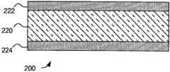
图2D示出其中压敏层200包括压敏材料220和两个绝缘体222、224的示例。在这个实施例中,绝缘体222和224设置在压敏材料220的相对表面上。FIG. 2D shows an example in which the pressure
各种不同材料能够用于图2B-2D的绝缘体。例如,绝缘体能够包括用于将压敏材料附连到输入装置的上或下元件的粘合层,例如包括传感器的其它部分的衬底。A variety of different materials can be used for the insulators of Figures 2B-2D. For example, the insulator can include an adhesive layer for attaching the pressure sensitive material to upper or lower elements of the input device, such as the substrate including other parts of the sensor.
现在来看图2E,示出另一个实施例,其中压敏层200包括多个压敏段228。在一个实施例中,按照直线阵或者另外某种图案来布置段228。在一个实施例中,段228的每个设置在主和辅助传感器电极(未示出)的汇合区(稍后更详细描述)之上。在另一个实施例中,段228的每个设置在至少一个主传感器电极或者至少一个辅助传感器电极之上。在其它示例中,段设置在主和辅助传感器电极附近的其它区域中。Turning now to FIG. 2E , another embodiment is shown in which the pressure
这个实施例的变化如图2F、图2G和图2H所示。在这些实施例的每个中,压敏层包括多个压敏段228和一个或多个绝缘体230。例如,图2F示出一个实施例,其中压敏层200包括在多个压敏段228下面的绝缘体230。作为另一个示例,图2G示出一个实施例,其中压敏层200包括在多个压敏段228上面的绝缘体230。作为另一个示例,图2H示出一个实施例,其中压敏层200包括在多个压敏段228上面和下面的绝缘体230。此外,在前面实施例的任一个中,绝缘体230可由多个绝缘体段组成,其中绝缘体段能够确定大小为相似于、小于或大于压敏段228。Variations of this embodiment are shown in Figures 2F, 2G and 2H. In each of these embodiments, the pressure sensitive layer includes a plurality of pressure
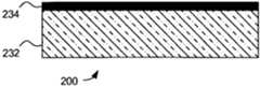
在一些实施例中,为了增强性能,导电元件可包含在压敏层上面、下面或里面。图2I示出一个实施例,其中压敏层200包括位于压敏材料232上面的导电元件234。图2J示出一个实施例,其中压敏层200包括位于压敏材料236下面的导电元件238。图2K示出一个实施例,其中压敏层200包括设置在压敏材料240里面的导电元件242。图2L示出一个实施例,其中压敏层200包括位于压敏材料250上面的多个导电元件252。在另一个实施例中,多个导电元件252位于压敏材料250下面。当压敏层响应所施加压力而改变其导纳率或变形时,导电元件能够增强导纳的变化。In some embodiments, conductive elements may be included on, under or in the pressure sensitive layer for enhanced performance. FIG. 2I shows an embodiment in which the pressure
因此,已经注意到,压敏层能够由大量材料并且采用大量几何形状来构成,并且不是要将本发明限制于本文所述的压敏层的示例。相反,在受到力或压力时引起两个附近传感器电极之间的电导纳的变化的任何材料层包含在本发明的范围之内。Thus, it has been noted that the pressure sensitive layer can be constructed from a wide variety of materials and in a wide variety of geometries, and it is not intended to limit the invention to the examples of pressure sensitive layers described herein. Rather, any layer of material that causes a change in electrical admittance between two nearby sensor electrodes when subjected to force or pressure is within the scope of the present invention.
单结点(node)实施例Single node (node) embodiment
现在来看图3,示出输入装置300的截面侧视图。输入装置300包括衬底层302、主传感器电极304、辅助传感器电极306、压敏层308和保护层310。在图3所示的实施例中,主和辅助传感器电极(例如电极304和306)在同一层上形成并且分隔某个水平距离。相比之下,在下面将论述的其它实施例中,主和辅助传感器电极可在之间有绝缘体层的独立层上形成。应当注意,虽然图3中示出所有这些元件,但是它们的一部分、如保护层310在某些实施例中可能不存在。Turning now to FIG. 3 , a cross-sectional side view of
图3所示的实施例能够按照各种方式来形成。例如,主和辅助传感器电极304、306可设置在衬底层302的一面上。但是,在其它实施例中,电极的一部分可设置在衬底层302的相对面上。在其它实施例中,主和辅助传感器电极304、306可按照重叠方式设置在衬底的同一面上,在它们重叠的位置通过绝缘体来分隔。在一个实施例中,主和辅助传感器电极能够配置成用作接近传感器或者“接近按钮”供用户输入。注意,图3的构造能够扩展成结合多个主传感器电极和/或多个辅助传感器电极,从而实现诸如滚动条、多个接近按钮集合以及能够检测多个物体并且确定多维的位置信息的通用物体检测器之类的输入装置。The embodiment shown in Figure 3 can be formed in various ways. For example, primary and
一般来说,主传感器电极304和辅助传感器电极306经由电导纳来耦合。当诸如手指312之类的输入物体接近输入装置300(即,在输入装置300的感测区之内)时,它们引起电极之间的导纳的变化。导纳的这个变化能够被测量,并且用于生成输入物体的位置信息。In general, the
诸如手指312之类的输入物体还可对输入装置300施加压力。具体来说,手指312能够压在输入装置的保护层310上。手指312压在保护层310上又对压敏层308施加压力(或力)。这个压力改变压敏层308的导纳率,从而引起电极304与306之间的导纳的进一步变化。这种进一步变化的量度可用于确定对保护层310施加压力的物体的压力信息。An input object such as a
在一个具体实现中,主传感器电极304与辅助传感器电极306之间的导纳能够是倒介电导纳或者跨电容。跨电容的变化(例如增加或减小)的方向(符号)将取决于物体的类型,例如物体是导电还是非导电的。因此,跨电容的变化的符号可用于确定对保护层310(或者当保护层310不存在时对压敏层308)施加压力的物体是导电物体还是非导电物体。变化的符号能够用于确定输入物体类型。In one specific implementation, the admittance between the
在一个实施例中,压敏层308选择成响应压力而增加电导率,并且主传感器电极304与辅助传感器电极306之间的导纳是导电导纳或电导。在这种实施例中,压敏层308在没有施加压力时可具有极低电导率,并且因而本质上可以是绝缘体。当施加压力时,电导率在施加压力的区域附近的层的区域中增加。这种电导率增加的速率和范围取决于压敏层308中使用的材料。In one embodiment, pressure
在各个实施例中,为了确定输入物体的压力信息,可使用阈值水平。考虑导电物体触摸保护层310,其中导电物体足够大以完全覆盖主传感器电极304和辅助传感器电极306的汇合区。当这种导电物体没有施加充分压力以引起压敏层308的导纳率的变化时,它产生所测量导纳的幅值的变化的阈值水平。超过这个阈值水平的所测量导纳的幅值的任何进一步变化可能是压敏层308的导纳率的变化结果,并且因此能够用作由导电物体对保护层310所施加的压力的量度。In various embodiments, to determine pressure information for an input object, a threshold level may be used. Consider a conductive object touching the
相反,触摸表面附近但没有施加明显压力的诸如触控笔之类的非导电物体将不会引起所测量导纳的幅值的明显变化,并且因而通常将不是可检测的。但是,当非导电物体对保护层310(并且由此对压敏层308)施加压力时,它引起所测量导纳的幅值的变化。所测量导纳的幅值的变化量是由非导电物体对保护层310所施加的压力的量度。联系在一起,导纳的量度的确定可用于确定感测区中和/或对保护层310施加压力的物体的位置信息、压力信息和/或类型信息。Conversely, a non-conductive object such as a stylus touching the vicinity of the surface without applying appreciable pressure will cause no appreciable change in the magnitude of the measured admittance, and thus will generally not be detectable. However, when a non-conductive object exerts pressure on the protective layer 310 (and thus the pressure sensitive layer 308), it causes a change in the magnitude of the measured admittance. The amount of change in the magnitude of the measured admittance is a measure of the pressure exerted on the
各种不同材料和技术能够用于形成主传感器电极304和辅助传感器电极306。例如,这些电极能够使用诸如ITO(氧化铟锡)、银或碳导电墨水或者铜之类的导电材料来形成图案。此外,可使用任何适当的图案形成过程,包括溅射沉积、印刷和蚀刻。A variety of different materials and techniques can be used to form the
保护层310设置在压敏层308上。通常,保护层310包括允许压力或力被传送到压敏层308的柔性材料。在一个实施例中,镶嵌(applique)用作保护层310。在一个实施例中,保护层310包括触摸表面,并且形成设计成由用户触摸的触摸传感器的一部分。当用作触摸表面时,保护层310优选地具有舒适触觉感或质地。由于这种触摸表面是用户可观看的,所以它优选地还具有舒适视觉质地。保护层310能够由任何适当材料来形成。例如,保护层310能够使用诸如以商标名MYLAR销售之类的一片纹面聚酯材料(textured polyestermaterial)来形成。在使用聚酯的情况下,保护层310能够具有任何适当厚度。在许多实施例中,保护层包括其下侧的粘合剂,用于将其固定到压敏层308的顶部或者固定到包含压敏层308的衬底。A
用于形成保护层310的材料的范围能够从完全不透明到完全透明。保护层310的表面可涂漆或者以其它方式着色,以便提供均匀外观。作为替代或补充,能够(例如经由)丝网印刷涂敷标志、文字、图形、它们的组合或者其它图案,来代替均匀涂漆层。往往将这类装饰嵌入或涂敷在保护层的背面,使得保护它们以避免在使用期间磨损。适合于保护层310的其它材料包括各种塑料,其中包括聚对苯二甲酸乙二醇酯(PET)、聚酰亚胺和聚碳酸酯(有时以商标名LEXAN销售)、它们的组合等等。在采用聚碳酸酯的一个实施例中,保护层的薄板厚度往往在大约0.1mm至大约0.6mm的范围之内。Materials used to form
在一些实施例中,可能希望将压敏层308与传感器电极绝缘,以使得压敏层没有与传感器电极进行欧姆接触。这可采用压敏层308与电极之间的充分分隔来实现。作为替代或补充,绝缘层可设置在压敏层308与传感器电极之间。对于下面将更详细描述的一些明晰的实施例,主传感器电极304和辅助传感器电极306还能够在(离压敏层更远的)底衬底的下侧上形成图案,或者诸如PET片之类的薄绝缘材料能够放置在传感器电极上面(即,在传感器电极与压敏层308之间)。例如,PET片可放置在主和辅助传感器电极之上,在气隙和柔性层之下。In some embodiments, it may be desirable to insulate the pressure
现在来看图4,示出输入装置400的截面侧视图。与输入装置300相似,输入装置400包括衬底层402、主传感器电极404、辅助传感器电极406、压敏层408和保护层410。这个实施例与图3所示实施例的不同之处在于,电极404和406位于压敏层408与保护层410之间。这个实施例可在很大程度上像以上参照图3所述那样操作;但是,在这个实施例中,压力通过主传感器电极404和辅助感测电极406传送到压敏层408。因此,输入装置能够确定位置和压力信息,并且在一些实施例中能够确定施加压力的物体的类型。Turning now to FIG. 4 , a cross-sectional side view of
现在来看图5,示出示范输入装置500的截面侧视图。输入装置500包括绝缘层502、主传感器电极504和辅助传感器电极506。这个实施例与图3所示实施例的不同之处在于,主传感器电极和辅助传感器电极处于不同层上,通过绝缘层来分隔。最后,保护层510覆盖压敏层308。Turning now to FIG. 5 , a cross-sectional side view of an exemplary input device 500 is shown. The input device 500 includes an insulating layer 502 , a main sensor electrode 504 and an auxiliary sensor electrode 506 . This embodiment differs from the embodiment shown in FIG. 3 in that the main and auxiliary sensor electrodes are on different layers, separated by an insulating layer. Finally, a protective layer 510 covers the pressure
多结点实施例multi-node embodiment
图5所示的实施例是仅包括一个主传感器电极504和一个辅助传感器电极506的输入装置500。这种实施例能够确定零维位置信息以及每次确定一个物体的压力和类型信息。其它实现可包括共同设置的多个主和/或多个辅助传感器电极,从而实现同时确定多个输入物体的这种信息的能力。另外,这类装置通常能够确定更大范围的位置信息,例如先前所述的一维和二维位置信息。下面将描述多个这些不同的实施例。The embodiment shown in FIG. 5 is an input device 500 including only one main sensor electrode 504 and one auxiliary sensor electrode 506 . Such an embodiment is capable of determining zero-dimensional position information as well as pressure and type information one object at a time. Other implementations may include multiple primary and/or multiple secondary sensor electrodes co-located, enabling the ability to simultaneously determine such information for multiple input objects. Additionally, such devices are generally capable of determining a larger range of positional information, such as the one-dimensional and two-dimensional positional information previously described. A number of these different embodiments are described below.
现在来看图6,示出示范输入装置600的顶视图。在这个实施例中,输入装置600包括一组主传感器电极604、一组辅助传感器电极606和设置在它们上面的压敏层308。在这类实施例中,存在主和辅助传感器电极在物理上充分接近以便经历实质电耦合的位置。这些位置在本文中称作汇合区,并且表示能够测量独立导纳的位置。在这个实施例中,汇合区位于主和辅助传感器电极的各交叉点周围。每个这种汇合区能够被认为是输入装置600的检测结点。在其它实施例中,汇合区位于主传感器电极和辅助传感器电极在物理上彼此相邻的位置。因此,汇合区和对应检测结点在各个实施例中能够按照许多方式来形成,包括交织、相互交叉、跨接和编结(interwine)至少一个主和至少一个辅助传感器电极。Turning now to FIG. 6 , a top view of an
图6的输入装置600能够被看作是图5所示输入装置500的扩展,其中使用多个主传感器电极和多个辅助传感器电极来形成多个汇合区。因此,输入装置600可配置成确定更大范围的位置信息以及在感测区中同时确定多个物体的位置和压力信息或者感测区中的较大物体的多个部分的位置和压力信息,例如手掌上的多个点。The
在这个所示实施例中,主传感器电极604的集合沿第一方向对齐,而辅助传感器电极606的集合沿第二方向对齐。具体来说,较宽的水平条表示主传感器电极604。同时,窄垂直条(部分被压敏层608遮掩)表示辅助传感器电极606。主和辅助传感器电极均能够制作为印刷电路的一部分,包括柔性或刚性触摸传感器电路板。因此,主和辅助传感器电极能够设置在包括一个或多个衬底并且形成整个电路部件的部分或全部的衬底部件上。在主和辅助传感器电极设置在同一衬底上的情况下,它们能够设置在衬底的同一侧、衬底的相对侧或者它们两者(例如,在部分传感器电极放置于衬底的两侧的情况下)。要理解,图6所示实施例的许多不同变化是可行的。例如,压敏层608能够分割为多段。In this illustrated embodiment, the set of primary sensor electrodes 604 are aligned along a first direction and the set of
现在来看图7,图7示出按照一个相似实施例的输入装置700的截面侧视图。输入装置700包括全部在衬底702上形成的一组主传感器电极704、一组辅助传感器电极706和压敏层708。联系在一起,主传感器电极704和辅助传感器电极706可称作传感器电极。绝缘层712在主传感器电极704的集合与辅助传感器电极706的集合之间形成。在这个取向中,压敏层位于传感器电极“上面”。在这种情况下,“上面”作为取向用于表示“更靠近在装置的正常操作期间预计输入物体所在的位置”。压敏层708配置成重叠至少一个传感器电极的至少一部分。Turning now to FIG. 7, FIG. 7 shows a cross-sectional side view of an
如图7所示,主和辅助传感器电极设置在衬底702上。衬底702能够包括各种不同布置和材料,例如玻璃或塑料(一种常见塑料衬底是聚对苯二甲酸乙二醇酯,缩写为PET)。其它类型的材料的衬底也是可能的。除了这些类型的材料之外,衬底702还可包括多个层,例如导电材料或非导电材料层。这些其它层可提供电屏蔽、物理保护、紧固能力等等。还应当注意,衬底702可以是较大衬底部件的一部分。As shown in FIG. 7 , primary and secondary sensor electrodes are disposed on a
这个实施例中所示的还有位于压敏层708上面的顶部保护层710。如上所述,用户能够按压保护层710,并且由此向压敏层708传送压力。如上所述并且下面将更详细描述,主与辅助传感器电极之间的导纳的所产生变化可用于提供施加到保护层的压力的量度,和/或确定施加压力的物体的类型。Also shown in this embodiment is a top
此外,由于能够对主传感器电极704和辅助传感器电极706的各汇合区确定导纳的量度,所以装置700便于确定一系列位置和压力信息。多个汇合区的所测量导纳的集合能够表示为包含与感测区中的所有物体有关的信息的二维导纳图像。通过检查这个二维图像,“尖峰”和“凹陷”能够定位并且解释为对应于手指或其它物体的位置。这些尖峰的高度和这些凹陷的深度能够提供每个输入物体的压力的单独量度,并且这些尖峰和凹陷的横向广度(lateral extent)能够用于确定物体的大小和形状。物体的存在是产生尖峰还是凹陷取决于物体的电性质,例如其电导率。因此,装置700便于识别不同类型的输入物体。Furthermore, since a measure of admittance can be determined for each junction of
测量输入物体压力的能力能够极大地帮助拒绝无意输入,这在输入物体或手指偶然轻轻地擦过输入装置表面时可能发生。另外,在导电物体和非导电物体之间或者在较大物体和较小物体之间进行区分的能力提供许多优点。例如,它能够用于在触控笔和手均同时存在于感测区时对其加以区分。在本发明的一些实施例中,手在导纳图像中显露为(show up)大“凹陷”,而触控笔显露为锐锋形(sharppeak)。对于本发明之前现有的许多常规输入装置,感测区中存在的手将干预触控笔的可靠检测。The ability to measure the pressure of an input object can greatly assist in rejecting inadvertent input, which can occur when an input object or a finger is accidentally brushed across the surface of the input device. Additionally, the ability to distinguish between conductive and non-conductive objects or between larger and smaller objects provides many advantages. For example, it can be used to distinguish between a stylus and a hand when both are present in the sensing area. In some embodiments of the invention, the hand shows up as a large "dimple" in the admittance image, while the stylus shows up as a sharp peak. With many conventional input devices that existed prior to the present invention, the presence of a hand in the sensing area would interfere with reliable detection of the stylus.
在图6和图7所示的实施例中,主和辅助传感器电极分别以行和列设置。此外,每个主传感器电极与其它主传感器电极平行对齐,而每个辅助传感器电极与其它辅助传感器电极平行对齐。如图6所示,主传感器电极604垂直对齐辅助传感器电极606;但是,对齐无需是90度,而是能够以任何其它角度,例如45度、60度等。此外,不存在关于传感器电极为直线或者相互平行的要求。在一些实施例中,主和辅助传感器电极可设置成使得至少一个主传感器电极与至少一个辅助传感器电极编结在一起,或者使得至少一个主传感器电极与至少一个辅助传感器电极交织在一起。下面将说明和论述这些实施例的更详细示例。In the embodiments shown in Figures 6 and 7, the main and auxiliary sensor electrodes are arranged in rows and columns, respectively. Furthermore, each main sensor electrode is aligned in parallel with other main sensor electrodes, and each auxiliary sensor electrode is aligned in parallel with other auxiliary sensor electrodes. As shown in Figure 6, the primary sensor electrodes 604 are vertically aligned with the
在图7所示的实施例中,绝缘层712设置在各表示独立层的主传感器电极704与辅助传感器电极706之间。在另一个实施例中,主传感器电极的至少一部分能够在与辅助传感器电极的至少一部分相同的层上形成图案。在这种实施例中,如果主传感器电极和辅助传感器电极需要相互交错,则能够适当地在主与辅助传感器电极之间的相交处使用跳线(jumper),以便防止不希望的电接触。同一层上形成的主和辅助传感器电极的电极结构的示例如图3和图4所示。In the embodiment shown in FIG. 7 , insulating
还应当注意,在许多这些实施例中,压敏层能够实现为重叠多个主和辅助传感器电极的单个结构。相反,这类装置还能够采用多个压敏层来实现。在一个具体实施例中,压敏层包括在主传感器电极与辅助传感器电极之间的各汇合区(例如相交位置)之上形成的多个压敏段。It should also be noted that in many of these embodiments, the pressure sensitive layer can be realized as a single structure overlapping multiple primary and secondary sensor electrodes. Instead, such devices can also be realized using multiple pressure sensitive layers. In a specific embodiment, the pressure sensitive layer includes a plurality of pressure sensitive segments formed over each junction region (eg, intersection location) between the primary sensor electrode and the secondary sensor electrode.
现在来看图8,示出输入装置800的截面侧视图。与图7的输入装置相似,这个输入装置800包括衬底层802、一组主传感器电极804、一组辅助传感器电极806、压敏层808和保护层810。在这个实施例中,主传感器电极804和辅助传感器电极806再次处于不同层上,并且通过绝缘体层812来分隔。但是,这个实施例与图7所述实施例的不同之处在于,传感器电极804和806位于压敏层808与保护层810之间。再则,这种实施例在很大程度上将像以上参照图6和图7所述那样操作;但是,在这个实施例中,压力通过主传感器电极804和辅助感测电极806传送到压敏层808。因此,输入装置能够确定位置和压力信息,并且在一些实施例中能够确定施加压力的物体的类型。Turning now to FIG. 8 , a cross-sectional side view of an
现在来看图9,示出输入装置900的截面侧视图。与先前的装置相似,这个输入装置900包括衬底层902、一组主传感器电极904、一组辅助传感器电极906、压敏层908和保护层910。并且此外,在这个实施例中,主传感器电极904和辅助传感器电极906处于不同层上。但是,在这个实施例中,两组传感器电极通过压敏层908来分隔。在这个示例中,当输入物体接近传感器时,主和辅助传感器电极能够用于确定输入物体的位置信息。此外,当输入物体对保护层910施加压力时,压力将被传送到压敏层,并且主与辅助传感器电极之间的导纳将发生变化。此外,这种实施例能够一般像以上参照图6和图7所述那样操作。因此,输入装置能够确定位置和压力信息,并且在一些实施例中能够确定施加压力的物体的类型。Turning now to FIG. 9 , a cross-sectional side view of an
现在来看图10,示出输入装置1000的截面侧视图。该输入装置包括衬底层1002、一组主传感器电极1004、一组辅助传感器电极1006、压敏层1008、压敏材料1016、一组电浮置导电元件(electrically floating conductive element)1014、保护层1010和绝缘层1012。如上所述,在这个实施例中,主传感器电极1004和辅助传感器电极1006处于不同层上,并且位于压敏层1008下面。但是,在这个实施例中,一组电浮置导电元件1014定位在压敏材料1016上面。在另一个实施例中,电浮置导电元件1010定位在辅助传感器电极1006与压敏材料1016之间。Turning now to FIG. 10 , a cross-sectional side view of an
在本文所述的结合了至少一个主传感器电极和至少一个辅助传感器电极的所有实施例中,名称“主”和“辅助”是任意的。另一组同样有用的实施例能够通过在这些实施例的每个中交换标签“主”和“辅助”来得到。In all embodiments described herein that incorporate at least one main sensor electrode and at least one auxiliary sensor electrode, the designations "main" and "auxiliary" are arbitrary. Another set of equally useful embodiments can be obtained by swapping the labels "primary" and "secondary" in each of these embodiments.
自导纳实施例Self Admittance Example
图11示出其中压敏层1108设置在单个传感器电极1104之上的一个实施例的截面图。传感器电极1104设置在衬底1102的表面上。在一个实施例中,传感器电极1104能够配置成用作接近按钮,对诸如用户手指之类的输入物体的存在进行响应。在另一个实施例中,多个传感器电极能够配置成用作多个接近按钮,或者电极阵列能够用作滚动条来确定一维位置信息。传感器1100能够通过测量传感器电极1104与输入物体1112之间的导纳的变化,来检测输入物体的存在。传感器电极1104与输入物体1112之间的这个导纳有时称作“自导纳”。FIG. 11 shows a cross-sectional view of an embodiment in which a pressure
在一个实施例中,为了测量传感器电极与输入物体之间的导纳的变化,将电信号驱动到传感器电极上,并且测量那个信号的性质。例如,能够将电压信号驱动到传感器电极上,并且测量所产生电流。根据所测量性质(例如所测量电流)能够确定导纳的变化。当输入物体1112向保护层1110移动时,所测量自导纳将发生变化,因而提供物体位置的确定。此外,当输入物体1112对保护层1110施加压力时,压敏层1108将改变其导纳率,从而进一步改变所测量自导纳,并且因而提供所施加压力的确定。In one embodiment, to measure the change in admittance between a sensor electrode and an input object, an electrical signal is driven onto the sensor electrode, and properties of that signal are measured. For example, it is possible to drive a voltage signal onto a sensor electrode and measure the resulting current. The change in admittance can be determined from the measured property (eg, the measured current). As the
图12是其中压敏层1208设置在一组主传感器电极1204和一组辅助传感器电极1206上面的一个实施例的截面图。在操作期间,传感器1200配置成通过确定主传感器电极1204的每个与输入物体1212之间以及辅助传感器电极1206的每个与输入物体1212之间的导纳的变化,来检测输入物体1212的位置信息和/或压力信息。能够按照与以上对于图11的传感器电极所述的相同方式,每次一个或者一个或多个编组同时地确定图12中的每个传感器电极的导纳。12 is a cross-sectional view of an embodiment in which a pressure
在这个实施例中,输入物体1212与主和辅助传感器电极(1204和1206)中的至少一个电耦合,从而引起导纳的变化,并且因而提供输入物体的位置信息的确定。当输入物体1212对保护层1210施加压力时,压敏层1208将改变其导纳率,从而进一步改变导纳,并且因而提供所施加压力的确定。In this embodiment, an
此外,由于能够确定输入物体1212与主传感器电极1204和辅助传感器电极1206的每个之间的导纳的量度,所以装置1200便于确定多维位置和压力信息。所测量导纳能够表示为沿传感器装置1200的第一和第二轴的两个一维曲线(profile)。这些一维曲线能够被认为是沿各轴的导纳的变化的轮廓(silhouette)或投影,并且能够用于确定输入物体的位置和/或压力。各曲线能够被解释为表示手指或其它物体的位置。这些曲线的高度能够提供与每个输入物体所施加的压力相关的信息,并且这些曲线的横向广度能够提供与物体的大小和形状相关的信息。在一些实施例中,当一组传感器电极采用电信号来驱动以检测输入物体时,另一组传感器电极可采用保护信号来驱动以降低两组传感器电极之间的寄生耦合的影响。Furthermore, due to the ability to determine a measure of admittance between the
结论in conclusion
因此,本发明的实施例提供通过使用压敏层来便于改进的输入装置性能的装置和方法,其中压敏层配置成响应施加到触摸表面的压力而改变一个或多个电导纳。Accordingly, embodiments of the present invention provide devices and methods that facilitate improved input device performance through the use of pressure sensitive layers configured to change one or more electrical admittances in response to pressure applied to a touch surface.
在一些实施例中,提供一种输入装置,它包括多个传感器电极,其中包括一个或多个主传感器电极的集合和一个或多个辅助传感器电极的集合。主传感器电极电耦合到辅助传感器电极,以便形成一个或多个导纳的集合。在一个这样的实施例中,压敏层位于传感器电极与触摸表面之间。In some embodiments, an input device is provided that includes a plurality of sensor electrodes, including a set of one or more primary sensor electrodes and a set of one or more auxiliary sensor electrodes. The primary sensor electrode is electrically coupled to the secondary sensor electrode so as to form a collection of one or more admittances. In one such embodiment, a pressure sensitive layer is located between the sensor electrodes and the touch surface.
在其它实施例中,提供一种输入装置,它包括与输入物体电耦合以形成一个或多个导纳的集合的一个或多个传感器电极的集合。在一个这样的实施例中,压敏层位于传感器电极与触摸表面之间。In other embodiments, an input device is provided that includes a set of one or more sensor electrodes electrically coupled to an input object to form a set of one or more admittances. In one such embodiment, a pressure sensitive layer is located between the sensor electrodes and the touch surface.
Claims (39)
Applications Claiming Priority (5)
| Application Number | Priority Date | Filing Date | Title |
|---|---|---|---|
| US18380909P | 2009-06-03 | 2009-06-03 | |
| US61/183809 | 2009-06-03 | ||
| US12/792578 | 2010-06-02 | ||
| US12/792,578US9383881B2 (en) | 2009-06-03 | 2010-06-02 | Input device and method with pressure-sensitive layer |
| PCT/US2010/037279WO2010141737A2 (en) | 2009-06-03 | 2010-06-03 | Input device and method with pressure-sensitive layer |
Publications (2)
| Publication Number | Publication Date |
|---|---|
| CN102449583Atrue CN102449583A (en) | 2012-05-09 |
| CN102449583B CN102449583B (en) | 2017-12-19 |
Family
ID=43298523
Family Applications (1)
| Application Number | Title | Priority Date | Filing Date |
|---|---|---|---|
| CN201080024918.XAExpired - Fee RelatedCN102449583B (en) | 2009-06-03 | 2010-06-03 | Input device and method with pressure sensitive layer |
Country Status (5)
| Country | Link |
|---|---|
| US (1) | US9383881B2 (en) |
| EP (1) | EP2438501A4 (en) |
| JP (1) | JP5679235B2 (en) |
| CN (1) | CN102449583B (en) |
| WO (1) | WO2010141737A2 (en) |
Cited By (24)
| Publication number | Priority date | Publication date | Assignee | Title |
|---|---|---|---|---|
| CN104969158A (en)* | 2012-12-14 | 2015-10-07 | 苹果公司 | Force sensing through capacitance changes |
| CN105022541A (en)* | 2013-10-01 | 2015-11-04 | 辛纳普蒂克斯公司 | Display guarding techniques |
| CN105103102A (en)* | 2013-08-16 | 2015-11-25 | 株式会社和冠 | Indicator detection device and indicator detection method |
| CN105278735A (en)* | 2014-06-16 | 2016-01-27 | 辛纳普蒂克斯公司 | Device and method for proximity sensing with force imaging |
| CN105320375A (en)* | 2014-06-03 | 2016-02-10 | 辛纳普蒂克斯公司 | Noise detection and mitigation for capacitive sensing devices |
| CN105446548A (en)* | 2014-09-19 | 2016-03-30 | 希迪普公司 | Touch input device |
| CN106030483A (en)* | 2014-02-18 | 2016-10-12 | 剑桥触控科技有限公司 | Dynamic switching of power modes for touch screens using force touch |
| CN106502481A (en)* | 2015-09-08 | 2017-03-15 | 深圳莱宝高科技股份有限公司 | A kind of touch control display apparatus and preparation method thereof |
| US9671889B1 (en) | 2013-07-25 | 2017-06-06 | Apple Inc. | Input member with capacitive sensor |
| CN106940603A (en)* | 2017-03-15 | 2017-07-11 | 上海大学 | A kind of touch sensing and preparation method |
| US9715301B2 (en) | 2015-08-04 | 2017-07-25 | Apple Inc. | Proximity edge sensing |
| US9851828B2 (en) | 2013-03-15 | 2017-12-26 | Apple Inc. | Touch force deflection sensor |
| CN107787475A (en)* | 2015-09-02 | 2018-03-09 | 希迪普公司 | The touch input device of sensing touch pressure |
| CN107930121A (en)* | 2017-12-12 | 2018-04-20 | 苏州蜗牛数字科技股份有限公司 | A kind of method and device moved according to input equipment Type Control Mission Objective |
| US10007343B2 (en) | 2016-03-31 | 2018-06-26 | Apple Inc. | Force sensor in an input device |
| US10006937B2 (en) | 2015-03-06 | 2018-06-26 | Apple Inc. | Capacitive sensors for electronic devices and methods of forming the same |
| US10048789B2 (en) | 2014-02-12 | 2018-08-14 | Apple Inc. | Force determination employing sheet sensor and capacitive array |
| US10162444B2 (en) | 2012-12-14 | 2018-12-25 | Apple Inc. | Force sensor incorporated into display |
| US10198123B2 (en) | 2014-04-21 | 2019-02-05 | Apple Inc. | Mitigating noise in capacitive sensor |
| CN109690460A (en)* | 2016-09-07 | 2019-04-26 | 触觉实验室股份有限公司 | Pressure and shear sensors |
| US10386970B2 (en) | 2013-02-08 | 2019-08-20 | Apple Inc. | Force determination based on capacitive sensing |
| CN111670013A (en)* | 2017-12-21 | 2020-09-15 | 爱惜康有限责任公司 | Surgical instrument including a display |
| US10866683B2 (en) | 2018-08-27 | 2020-12-15 | Apple Inc. | Force or touch sensing on a mobile device using capacitive or pressure sensing |
| CN113204291A (en)* | 2021-05-18 | 2021-08-03 | 业成科技(成都)有限公司 | Touch control display |
Families Citing this family (482)
| Publication number | Priority date | Publication date | Assignee | Title |
|---|---|---|---|---|
| US20070084897A1 (en) | 2003-05-20 | 2007-04-19 | Shelton Frederick E Iv | Articulating surgical stapling instrument incorporating a two-piece e-beam firing mechanism |
| US9060770B2 (en) | 2003-05-20 | 2015-06-23 | Ethicon Endo-Surgery, Inc. | Robotically-driven surgical instrument with E-beam driver |
| US9072535B2 (en) | 2011-05-27 | 2015-07-07 | Ethicon Endo-Surgery, Inc. | Surgical stapling instruments with rotatable staple deployment arrangements |
| US11890012B2 (en) | 2004-07-28 | 2024-02-06 | Cilag Gmbh International | Staple cartridge comprising cartridge body and attached support |
| US8215531B2 (en) | 2004-07-28 | 2012-07-10 | Ethicon Endo-Surgery, Inc. | Surgical stapling instrument having a medical substance dispenser |
| US11998198B2 (en) | 2004-07-28 | 2024-06-04 | Cilag Gmbh International | Surgical stapling instrument incorporating a two-piece E-beam firing mechanism |
| US11246590B2 (en) | 2005-08-31 | 2022-02-15 | Cilag Gmbh International | Staple cartridge including staple drivers having different unfired heights |
| US10159482B2 (en) | 2005-08-31 | 2018-12-25 | Ethicon Llc | Fastener cartridge assembly comprising a fixed anvil and different staple heights |
| US7934630B2 (en) | 2005-08-31 | 2011-05-03 | Ethicon Endo-Surgery, Inc. | Staple cartridges for forming staples having differing formed staple heights |
| US11484312B2 (en) | 2005-08-31 | 2022-11-01 | Cilag Gmbh International | Staple cartridge comprising a staple driver arrangement |
| US7669746B2 (en) | 2005-08-31 | 2010-03-02 | Ethicon Endo-Surgery, Inc. | Staple cartridges for forming staples having differing formed staple heights |
| US9237891B2 (en) | 2005-08-31 | 2016-01-19 | Ethicon Endo-Surgery, Inc. | Robotically-controlled surgical stapling devices that produce formed staples having different lengths |
| US20070106317A1 (en) | 2005-11-09 | 2007-05-10 | Shelton Frederick E Iv | Hydraulically and electrically actuated articulation joints for surgical instruments |
| US20120292367A1 (en) | 2006-01-31 | 2012-11-22 | Ethicon Endo-Surgery, Inc. | Robotically-controlled end effector |
| US7753904B2 (en) | 2006-01-31 | 2010-07-13 | Ethicon Endo-Surgery, Inc. | Endoscopic surgical instrument with a handle that can articulate with respect to the shaft |
| US8186555B2 (en) | 2006-01-31 | 2012-05-29 | Ethicon Endo-Surgery, Inc. | Motor-driven surgical cutting and fastening instrument with mechanical closure system |
| US11793518B2 (en) | 2006-01-31 | 2023-10-24 | Cilag Gmbh International | Powered surgical instruments with firing system lockout arrangements |
| US20110024477A1 (en) | 2009-02-06 | 2011-02-03 | Hall Steven G | Driven Surgical Stapler Improvements |
| US7845537B2 (en) | 2006-01-31 | 2010-12-07 | Ethicon Endo-Surgery, Inc. | Surgical instrument having recording capabilities |
| US20110295295A1 (en) | 2006-01-31 | 2011-12-01 | Ethicon Endo-Surgery, Inc. | Robotically-controlled surgical instrument having recording capabilities |
| US11224427B2 (en) | 2006-01-31 | 2022-01-18 | Cilag Gmbh International | Surgical stapling system including a console and retraction assembly |
| US8708213B2 (en) | 2006-01-31 | 2014-04-29 | Ethicon Endo-Surgery, Inc. | Surgical instrument having a feedback system |
| US8820603B2 (en) | 2006-01-31 | 2014-09-02 | Ethicon Endo-Surgery, Inc. | Accessing data stored in a memory of a surgical instrument |
| US11278279B2 (en) | 2006-01-31 | 2022-03-22 | Cilag Gmbh International | Surgical instrument assembly |
| US8992422B2 (en) | 2006-03-23 | 2015-03-31 | Ethicon Endo-Surgery, Inc. | Robotically-controlled endoscopic accessory channel |
| US8322455B2 (en) | 2006-06-27 | 2012-12-04 | Ethicon Endo-Surgery, Inc. | Manually driven surgical cutting and fastening instrument |
| US10568652B2 (en) | 2006-09-29 | 2020-02-25 | Ethicon Llc | Surgical staples having attached drivers of different heights and stapling instruments for deploying the same |
| US11980366B2 (en) | 2006-10-03 | 2024-05-14 | Cilag Gmbh International | Surgical instrument |
| US11291441B2 (en) | 2007-01-10 | 2022-04-05 | Cilag Gmbh International | Surgical instrument with wireless communication between control unit and remote sensor |
| US8684253B2 (en) | 2007-01-10 | 2014-04-01 | Ethicon Endo-Surgery, Inc. | Surgical instrument with wireless communication between a control unit of a robotic system and remote sensor |
| US8632535B2 (en) | 2007-01-10 | 2014-01-21 | Ethicon Endo-Surgery, Inc. | Interlock and surgical instrument including same |
| US11039836B2 (en) | 2007-01-11 | 2021-06-22 | Cilag Gmbh International | Staple cartridge for use with a surgical stapling instrument |
| US20080169333A1 (en) | 2007-01-11 | 2008-07-17 | Shelton Frederick E | Surgical stapler end effector with tapered distal end |
| US7673782B2 (en) | 2007-03-15 | 2010-03-09 | Ethicon Endo-Surgery, Inc. | Surgical stapling instrument having a releasable buttress material |
| US8931682B2 (en) | 2007-06-04 | 2015-01-13 | Ethicon Endo-Surgery, Inc. | Robotically-controlled shaft based rotary drive systems for surgical instruments |
| US11564682B2 (en) | 2007-06-04 | 2023-01-31 | Cilag Gmbh International | Surgical stapler device |
| US7753245B2 (en) | 2007-06-22 | 2010-07-13 | Ethicon Endo-Surgery, Inc. | Surgical stapling instruments |
| US11849941B2 (en) | 2007-06-29 | 2023-12-26 | Cilag Gmbh International | Staple cartridge having staple cavities extending at a transverse angle relative to a longitudinal cartridge axis |
| US7819298B2 (en) | 2008-02-14 | 2010-10-26 | Ethicon Endo-Surgery, Inc. | Surgical stapling apparatus with control features operable with one hand |
| US7866527B2 (en) | 2008-02-14 | 2011-01-11 | Ethicon Endo-Surgery, Inc. | Surgical stapling apparatus with interlockable firing system |
| JP5410110B2 (en) | 2008-02-14 | 2014-02-05 | エシコン・エンド−サージェリィ・インコーポレイテッド | Surgical cutting / fixing instrument with RF electrode |
| US8636736B2 (en) | 2008-02-14 | 2014-01-28 | Ethicon Endo-Surgery, Inc. | Motorized surgical cutting and fastening instrument |
| US9179912B2 (en) | 2008-02-14 | 2015-11-10 | Ethicon Endo-Surgery, Inc. | Robotically-controlled motorized surgical cutting and fastening instrument |
| US8758391B2 (en) | 2008-02-14 | 2014-06-24 | Ethicon Endo-Surgery, Inc. | Interchangeable tools for surgical instruments |
| US11986183B2 (en) | 2008-02-14 | 2024-05-21 | Cilag Gmbh International | Surgical cutting and fastening instrument comprising a plurality of sensors to measure an electrical parameter |
| US8573465B2 (en) | 2008-02-14 | 2013-11-05 | Ethicon Endo-Surgery, Inc. | Robotically-controlled surgical end effector system with rotary actuated closure systems |
| US9585657B2 (en) | 2008-02-15 | 2017-03-07 | Ethicon Endo-Surgery, Llc | Actuator for releasing a layer of material from a surgical end effector |
| US9018030B2 (en) | 2008-03-20 | 2015-04-28 | Symbol Technologies, Inc. | Transparent force sensor and method of fabrication |
| US8210411B2 (en) | 2008-09-23 | 2012-07-03 | Ethicon Endo-Surgery, Inc. | Motor-driven surgical cutting instrument |
| US11648005B2 (en) | 2008-09-23 | 2023-05-16 | Cilag Gmbh International | Robotically-controlled motorized surgical instrument with an end effector |
| US9386983B2 (en) | 2008-09-23 | 2016-07-12 | Ethicon Endo-Surgery, Llc | Robotically-controlled motorized surgical instrument |
| US9005230B2 (en) | 2008-09-23 | 2015-04-14 | Ethicon Endo-Surgery, Inc. | Motorized surgical instrument |
| US8608045B2 (en) | 2008-10-10 | 2013-12-17 | Ethicon Endo-Sugery, Inc. | Powered surgical cutting and stapling apparatus with manually retractable firing system |
| US8517239B2 (en) | 2009-02-05 | 2013-08-27 | Ethicon Endo-Surgery, Inc. | Surgical stapling instrument comprising a magnetic element driver |
| RU2525225C2 (en) | 2009-02-06 | 2014-08-10 | Этикон Эндо-Серджери, Инк. | Improvement of drive surgical suturing instrument |
| JP2011017626A (en)* | 2009-07-09 | 2011-01-27 | Sony Corp | Mechanical quantity detection member and mechanical quantity detection apparatus |
| US8988191B2 (en) | 2009-08-27 | 2015-03-24 | Symbol Technologies, Inc. | Systems and methods for pressure-based authentication of an input on a touch screen |
| US9891757B2 (en)* | 2009-12-21 | 2018-02-13 | Synaptics Incorporated | Elastive sensing |
| US8851354B2 (en) | 2009-12-24 | 2014-10-07 | Ethicon Endo-Surgery, Inc. | Surgical cutting instrument that analyzes tissue thickness |
| US8220688B2 (en) | 2009-12-24 | 2012-07-17 | Ethicon Endo-Surgery, Inc. | Motor-driven surgical cutting instrument with electric actuator directional control assembly |
| DE102011006448A1 (en) | 2010-03-31 | 2011-10-06 | Tk Holdings, Inc. | steering wheel sensors |
| US8587422B2 (en) | 2010-03-31 | 2013-11-19 | Tk Holdings, Inc. | Occupant sensing system |
| DE102011006649B4 (en) | 2010-04-02 | 2018-05-03 | Tk Holdings Inc. | Steering wheel with hand sensors |
| US20110273394A1 (en)* | 2010-05-10 | 2011-11-10 | Symbol Technologies, Inc. | Methods and apparatus for a transparent and flexible force-sensitive touch panel |
| US8783543B2 (en) | 2010-07-30 | 2014-07-22 | Ethicon Endo-Surgery, Inc. | Tissue acquisition arrangements and methods for surgical stapling devices |
| EP2598942A4 (en) | 2010-07-30 | 2014-07-23 | Univ Leland Stanford Junior | CONDUCTIVE FILMS |
| US8963874B2 (en) | 2010-07-31 | 2015-02-24 | Symbol Technologies, Inc. | Touch screen rendering system and method of operation thereof |
| US9281415B2 (en) | 2010-09-10 | 2016-03-08 | The Board Of Trustees Of The Leland Stanford Junior University | Pressure sensing apparatuses and methods |
| US9629814B2 (en) | 2010-09-30 | 2017-04-25 | Ethicon Endo-Surgery, Llc | Tissue thickness compensator configured to redistribute compressive forces |
| US10945731B2 (en) | 2010-09-30 | 2021-03-16 | Ethicon Llc | Tissue thickness compensator comprising controlled release and expansion |
| US9386988B2 (en) | 2010-09-30 | 2016-07-12 | Ethicon End-Surgery, LLC | Retainer assembly including a tissue thickness compensator |
| US11298125B2 (en) | 2010-09-30 | 2022-04-12 | Cilag Gmbh International | Tissue stapler having a thickness compensator |
| US11925354B2 (en) | 2010-09-30 | 2024-03-12 | Cilag Gmbh International | Staple cartridge comprising staples positioned within a compressible portion thereof |
| US11812965B2 (en) | 2010-09-30 | 2023-11-14 | Cilag Gmbh International | Layer of material for a surgical end effector |
| US12213666B2 (en) | 2010-09-30 | 2025-02-04 | Cilag Gmbh International | Tissue thickness compensator comprising layers |
| US9351730B2 (en) | 2011-04-29 | 2016-05-31 | Ethicon Endo-Surgery, Llc | Tissue thickness compensator comprising channels |
| US9016542B2 (en) | 2010-09-30 | 2015-04-28 | Ethicon Endo-Surgery, Inc. | Staple cartridge comprising compressible distortion resistant components |
| US9788834B2 (en) | 2010-09-30 | 2017-10-17 | Ethicon Llc | Layer comprising deployable attachment members |
| US8695866B2 (en) | 2010-10-01 | 2014-04-15 | Ethicon Endo-Surgery, Inc. | Surgical instrument having a power control circuit |
| US8618428B2 (en) | 2010-12-14 | 2013-12-31 | Synaptics Incorporated | System and method for determining object information using an estimated rigid motion response |
| US9201185B2 (en) | 2011-02-04 | 2015-12-01 | Microsoft Technology Licensing, Llc | Directional backlighting for display panels |
| JP5689705B2 (en) | 2011-02-10 | 2015-03-25 | 任天堂株式会社 | Information processing system, information processing program, information processing device, input device, and information processing method |
| AU2012250197B2 (en) | 2011-04-29 | 2017-08-10 | Ethicon Endo-Surgery, Inc. | Staple cartridge comprising staples positioned within a compressible portion thereof |
| US11207064B2 (en) | 2011-05-27 | 2021-12-28 | Cilag Gmbh International | Automated end effector component reloading system for use with a robotic system |
| WO2013049816A1 (en) | 2011-09-30 | 2013-04-04 | Sensitronics, LLC | Hybrid capacitive force sensors |
| US9256311B2 (en)* | 2011-10-28 | 2016-02-09 | Atmel Corporation | Flexible touch sensor |
| US9052414B2 (en) | 2012-02-07 | 2015-06-09 | Microsoft Technology Licensing, Llc | Virtual image device |
| US9354748B2 (en) | 2012-02-13 | 2016-05-31 | Microsoft Technology Licensing, Llc | Optical stylus interaction |
| US8749529B2 (en) | 2012-03-01 | 2014-06-10 | Microsoft Corporation | Sensor-in-pixel display system with near infrared filter |
| DE112013001251T5 (en)* | 2012-03-02 | 2014-11-27 | Tokai Rubber Industries, Ltd. | hybrid sensor |
| US9075566B2 (en) | 2012-03-02 | 2015-07-07 | Microsoft Technoogy Licensing, LLC | Flexible hinge spine |
| US8873227B2 (en) | 2012-03-02 | 2014-10-28 | Microsoft Corporation | Flexible hinge support layer |
| US9298236B2 (en) | 2012-03-02 | 2016-03-29 | Microsoft Technology Licensing, Llc | Multi-stage power adapter configured to provide a first power level upon initial connection of the power adapter to the host device and a second power level thereafter upon notification from the host device to the power adapter |
| US9460029B2 (en) | 2012-03-02 | 2016-10-04 | Microsoft Technology Licensing, Llc | Pressure sensitive keys |
| US9360893B2 (en) | 2012-03-02 | 2016-06-07 | Microsoft Technology Licensing, Llc | Input device writing surface |
| US9426905B2 (en) | 2012-03-02 | 2016-08-23 | Microsoft Technology Licensing, Llc | Connection device for computing devices |
| US9064654B2 (en) | 2012-03-02 | 2015-06-23 | Microsoft Technology Licensing, Llc | Method of manufacturing an input device |
| US9870066B2 (en) | 2012-03-02 | 2018-01-16 | Microsoft Technology Licensing, Llc | Method of manufacturing an input device |
| USRE48963E1 (en) | 2012-03-02 | 2022-03-08 | Microsoft Technology Licensing, Llc | Connection device for computing devices |
| BR112014024098B1 (en) | 2012-03-28 | 2021-05-25 | Ethicon Endo-Surgery, Inc. | staple cartridge |
| JP6224070B2 (en) | 2012-03-28 | 2017-11-01 | エシコン・エンド−サージェリィ・インコーポレイテッドEthicon Endo−Surgery,Inc. | Retainer assembly including tissue thickness compensator |
| MX358135B (en) | 2012-03-28 | 2018-08-06 | Ethicon Endo Surgery Inc | Tissue thickness compensator comprising a plurality of layers. |
| US9665214B2 (en)* | 2012-03-29 | 2017-05-30 | Synaptics Incorporated | System and methods for determining object information using selectively floated electrodes |
| WO2013154720A1 (en) | 2012-04-13 | 2013-10-17 | Tk Holdings Inc. | Pressure sensor including a pressure sensitive material for use with control systems and methods of using the same |
| US20130300590A1 (en) | 2012-05-14 | 2013-11-14 | Paul Henry Dietz | Audio Feedback |
| US10031556B2 (en) | 2012-06-08 | 2018-07-24 | Microsoft Technology Licensing, Llc | User experience adaptation |
| US8947353B2 (en) | 2012-06-12 | 2015-02-03 | Microsoft Corporation | Photosensor array gesture detection |
| US9019615B2 (en) | 2012-06-12 | 2015-04-28 | Microsoft Technology Licensing, Llc | Wide field-of-view virtual image projector |
| US9459160B2 (en) | 2012-06-13 | 2016-10-04 | Microsoft Technology Licensing, Llc | Input device sensor configuration |
| US9073123B2 (en) | 2012-06-13 | 2015-07-07 | Microsoft Technology Licensing, Llc | Housing vents |
| US9684382B2 (en) | 2012-06-13 | 2017-06-20 | Microsoft Technology Licensing, Llc | Input device configuration having capacitive and pressure sensors |
| US9256089B2 (en) | 2012-06-15 | 2016-02-09 | Microsoft Technology Licensing, Llc | Object-detecting backlight unit |
| US9101358B2 (en) | 2012-06-15 | 2015-08-11 | Ethicon Endo-Surgery, Inc. | Articulatable surgical instrument comprising a firing drive |
| US9493342B2 (en) | 2012-06-21 | 2016-11-15 | Nextinput, Inc. | Wafer level MEMS force dies |
| US20140001231A1 (en) | 2012-06-28 | 2014-01-02 | Ethicon Endo-Surgery, Inc. | Firing system lockout arrangements for surgical instruments |
| BR112014032776B1 (en) | 2012-06-28 | 2021-09-08 | Ethicon Endo-Surgery, Inc | SURGICAL INSTRUMENT SYSTEM AND SURGICAL KIT FOR USE WITH A SURGICAL INSTRUMENT SYSTEM |
| US11278284B2 (en) | 2012-06-28 | 2022-03-22 | Cilag Gmbh International | Rotary drive arrangements for surgical instruments |
| US9289256B2 (en) | 2012-06-28 | 2016-03-22 | Ethicon Endo-Surgery, Llc | Surgical end effectors having angled tissue-contacting surfaces |
| US9282974B2 (en) | 2012-06-28 | 2016-03-15 | Ethicon Endo-Surgery, Llc | Empty clip cartridge lockout |
| JP6290201B2 (en) | 2012-06-28 | 2018-03-07 | エシコン・エンド−サージェリィ・インコーポレイテッドEthicon Endo−Surgery,Inc. | Lockout for empty clip cartridge |
| US9408606B2 (en) | 2012-06-28 | 2016-08-09 | Ethicon Endo-Surgery, Llc | Robotically powered surgical device with manually-actuatable reversing system |
| US12383267B2 (en) | 2012-06-28 | 2025-08-12 | Cilag Gmbh International | Robotically powered surgical device with manually-actuatable reversing system |
| EP2870445A1 (en) | 2012-07-05 | 2015-05-13 | Ian Campbell | Microelectromechanical load sensor and methods of manufacturing the same |
| US9355345B2 (en) | 2012-07-23 | 2016-05-31 | Microsoft Technology Licensing, Llc | Transparent tags with encoded data |
| US8964379B2 (en) | 2012-08-20 | 2015-02-24 | Microsoft Corporation | Switchable magnetic lock |
| WO2014043664A1 (en) | 2012-09-17 | 2014-03-20 | Tk Holdings Inc. | Single layer force sensor |
| US9152173B2 (en) | 2012-10-09 | 2015-10-06 | Microsoft Technology Licensing, Llc | Transparent display device |
| US8654030B1 (en) | 2012-10-16 | 2014-02-18 | Microsoft Corporation | Antenna placement |
| EP2908970B1 (en) | 2012-10-17 | 2018-01-03 | Microsoft Technology Licensing, LLC | Metal alloy injection molding protrusions |
| WO2014059618A1 (en) | 2012-10-17 | 2014-04-24 | Microsoft Corporation | Graphic formation via material ablation |
| WO2014059625A1 (en) | 2012-10-17 | 2014-04-24 | Microsoft Corporation | Metal alloy injection molding overflows |
| US8952892B2 (en) | 2012-11-01 | 2015-02-10 | Microsoft Corporation | Input location correction tables for input panels |
| US8786767B2 (en) | 2012-11-02 | 2014-07-22 | Microsoft Corporation | Rapid synchronized lighting and shuttering |
| US9513748B2 (en) | 2012-12-13 | 2016-12-06 | Microsoft Technology Licensing, Llc | Combined display panel circuit |
| US9141259B2 (en) | 2013-01-21 | 2015-09-22 | International Business Machines Corporation | Pressure navigation on a touch sensitive user interface |
| US9176538B2 (en) | 2013-02-05 | 2015-11-03 | Microsoft Technology Licensing, Llc | Input device configurations |
| US10578499B2 (en) | 2013-02-17 | 2020-03-03 | Microsoft Technology Licensing, Llc | Piezo-actuated virtual buttons for touch surfaces |
| RU2672520C2 (en) | 2013-03-01 | 2018-11-15 | Этикон Эндо-Серджери, Инк. | Hingedly turnable surgical instruments with conducting ways for signal transfer |
| BR112015021082B1 (en) | 2013-03-01 | 2022-05-10 | Ethicon Endo-Surgery, Inc | surgical instrument |
| US9638835B2 (en) | 2013-03-05 | 2017-05-02 | Microsoft Technology Licensing, Llc | Asymmetric aberration correcting lens |
| US9629629B2 (en) | 2013-03-14 | 2017-04-25 | Ethicon Endo-Surgey, LLC | Control systems for surgical instruments |
| US9808244B2 (en) | 2013-03-14 | 2017-11-07 | Ethicon Llc | Sensor arrangements for absolute positioning system for surgical instruments |
| US9304549B2 (en) | 2013-03-28 | 2016-04-05 | Microsoft Technology Licensing, Llc | Hinge mechanism for rotatable component attachment |
| BR112015026109B1 (en) | 2013-04-16 | 2022-02-22 | Ethicon Endo-Surgery, Inc | surgical instrument |
| US9826976B2 (en) | 2013-04-16 | 2017-11-28 | Ethicon Llc | Motor driven surgical instruments with lockable dual drive shafts |
| US9552777B2 (en) | 2013-05-10 | 2017-01-24 | Microsoft Technology Licensing, Llc | Phase control backlight |
| JP5713479B1 (en) | 2013-08-16 | 2015-05-07 | 株式会社ワコム | Indicator detection sensor and indicator detection apparatus |
| MX369362B (en) | 2013-08-23 | 2019-11-06 | Ethicon Endo Surgery Llc | Firing member retraction devices for powered surgical instruments. |
| US9775609B2 (en) | 2013-08-23 | 2017-10-03 | Ethicon Llc | Tamper proof circuit for surgical instrument battery pack |
| US8823399B1 (en)* | 2013-10-07 | 2014-09-02 | Cypress Semiconductor Corporation | Detect and differentiate touches from different size conductive objects on a capacitive button |
| US9483118B2 (en) | 2013-12-27 | 2016-11-01 | Rovi Guides, Inc. | Methods and systems for selecting media guidance functions based on tactile attributes of a user input |
| US9448631B2 (en) | 2013-12-31 | 2016-09-20 | Microsoft Technology Licensing, Llc | Input device haptics and pressure sensing |
| EP3094950B1 (en) | 2014-01-13 | 2022-12-21 | Nextinput, Inc. | Miniaturized and ruggedized wafer level mems force sensors |
| US9317072B2 (en) | 2014-01-28 | 2016-04-19 | Microsoft Technology Licensing, Llc | Hinge mechanism with preset positions |
| US9962161B2 (en) | 2014-02-12 | 2018-05-08 | Ethicon Llc | Deliverable surgical instrument |
| US9759854B2 (en) | 2014-02-17 | 2017-09-12 | Microsoft Technology Licensing, Llc | Input device outer layer and backlighting |
| US10120420B2 (en) | 2014-03-21 | 2018-11-06 | Microsoft Technology Licensing, Llc | Lockable display and techniques enabling use of lockable displays |
| US10013049B2 (en) | 2014-03-26 | 2018-07-03 | Ethicon Llc | Power management through sleep options of segmented circuit and wake up control |
| US10004497B2 (en) | 2014-03-26 | 2018-06-26 | Ethicon Llc | Interface systems for use with surgical instruments |
| US12232723B2 (en) | 2014-03-26 | 2025-02-25 | Cilag Gmbh International | Systems and methods for controlling a segmented circuit |
| BR112016021943B1 (en) | 2014-03-26 | 2022-06-14 | Ethicon Endo-Surgery, Llc | SURGICAL INSTRUMENT FOR USE BY AN OPERATOR IN A SURGICAL PROCEDURE |
| US20150272580A1 (en) | 2014-03-26 | 2015-10-01 | Ethicon Endo-Surgery, Inc. | Verification of number of battery exchanges/procedure count |
| BR112016023825B1 (en) | 2014-04-16 | 2022-08-02 | Ethicon Endo-Surgery, Llc | STAPLE CARTRIDGE FOR USE WITH A SURGICAL STAPLER AND STAPLE CARTRIDGE FOR USE WITH A SURGICAL INSTRUMENT |
| US20150297225A1 (en) | 2014-04-16 | 2015-10-22 | Ethicon Endo-Surgery, Inc. | Fastener cartridges including extensions having different configurations |
| CN106456176B (en) | 2014-04-16 | 2019-06-28 | 伊西康内外科有限责任公司 | Fastener Cartridge Including Extensions With Different Configurations |
| CN106456159B (en) | 2014-04-16 | 2019-03-08 | 伊西康内外科有限责任公司 | Fastener Cartridge Assembly and Nail Retainer Cover Arrangement |
| US10327764B2 (en) | 2014-09-26 | 2019-06-25 | Ethicon Llc | Method for creating a flexible staple line |
| US10470768B2 (en) | 2014-04-16 | 2019-11-12 | Ethicon Llc | Fastener cartridge including a layer attached thereto |
| US10324733B2 (en) | 2014-07-30 | 2019-06-18 | Microsoft Technology Licensing, Llc | Shutdown notifications |
| US11311294B2 (en) | 2014-09-05 | 2022-04-26 | Cilag Gmbh International | Powered medical device including measurement of closure state of jaws |
| US10135242B2 (en) | 2014-09-05 | 2018-11-20 | Ethicon Llc | Smart cartridge wake up operation and data retention |
| BR112017004361B1 (en) | 2014-09-05 | 2023-04-11 | Ethicon Llc | ELECTRONIC SYSTEM FOR A SURGICAL INSTRUMENT |
| US9424048B2 (en) | 2014-09-15 | 2016-08-23 | Microsoft Technology Licensing, Llc | Inductive peripheral retention device |
| US10105142B2 (en) | 2014-09-18 | 2018-10-23 | Ethicon Llc | Surgical stapler with plurality of cutting elements |
| US11523821B2 (en) | 2014-09-26 | 2022-12-13 | Cilag Gmbh International | Method for creating a flexible staple line |
| CN107427300B (en) | 2014-09-26 | 2020-12-04 | 伊西康有限责任公司 | Surgical suture buttresses and auxiliary materials |
| US9447620B2 (en) | 2014-09-30 | 2016-09-20 | Microsoft Technology Licensing, Llc | Hinge mechanism with multiple preset positions |
| US10076325B2 (en) | 2014-10-13 | 2018-09-18 | Ethicon Llc | Surgical stapling apparatus comprising a tissue stop |
| US9924944B2 (en) | 2014-10-16 | 2018-03-27 | Ethicon Llc | Staple cartridge comprising an adjunct material |
| US9501167B2 (en) | 2014-10-22 | 2016-11-22 | Synaptics Incorporated | Scanned piezoelectric touch sensor device |
| US11141153B2 (en) | 2014-10-29 | 2021-10-12 | Cilag Gmbh International | Staple cartridges comprising driver arrangements |
| US10517594B2 (en) | 2014-10-29 | 2019-12-31 | Ethicon Llc | Cartridge assemblies for surgical staplers |
| US9844376B2 (en) | 2014-11-06 | 2017-12-19 | Ethicon Llc | Staple cartridge comprising a releasable adjunct material |
| US10736636B2 (en) | 2014-12-10 | 2020-08-11 | Ethicon Llc | Articulatable surgical instrument system |
| US9519360B2 (en) | 2014-12-11 | 2016-12-13 | Synaptics Incorporated | Palm rejection visualization for passive stylus |
| MX389118B (en) | 2014-12-18 | 2025-03-20 | Ethicon Llc | SURGICAL INSTRUMENT WITH AN ANVIL THAT CAN BE SELECTIVELY MOVED ON A DISCRETE, NON-MOBILE AXIS RELATIVE TO A STAPLE CARTRIDGE. |
| US9844374B2 (en) | 2014-12-18 | 2017-12-19 | Ethicon Llc | Surgical instrument systems comprising an articulatable end effector and means for adjusting the firing stroke of a firing member |
| US9987000B2 (en) | 2014-12-18 | 2018-06-05 | Ethicon Llc | Surgical instrument assembly comprising a flexible articulation system |
| US9943309B2 (en) | 2014-12-18 | 2018-04-17 | Ethicon Llc | Surgical instruments with articulatable end effectors and movable firing beam support arrangements |
| US10085748B2 (en) | 2014-12-18 | 2018-10-02 | Ethicon Llc | Locking arrangements for detachable shaft assemblies with articulatable surgical end effectors |
| US9844375B2 (en) | 2014-12-18 | 2017-12-19 | Ethicon Llc | Drive arrangements for articulatable surgical instruments |
| US9495052B2 (en) | 2014-12-19 | 2016-11-15 | Synaptics Incorporated | Active input device support for a capacitive sensing device |
| US9791970B2 (en)* | 2014-12-22 | 2017-10-17 | Synaptics Incorporated | Method and system for dual node sensing |
| US11154301B2 (en) | 2015-02-27 | 2021-10-26 | Cilag Gmbh International | Modular stapling assembly |
| US10441279B2 (en) | 2015-03-06 | 2019-10-15 | Ethicon Llc | Multiple level thresholds to modify operation of powered surgical instruments |
| US10245033B2 (en) | 2015-03-06 | 2019-04-02 | Ethicon Llc | Surgical instrument comprising a lockable battery housing |
| US10687806B2 (en) | 2015-03-06 | 2020-06-23 | Ethicon Llc | Adaptive tissue compression techniques to adjust closure rates for multiple tissue types |
| US10617412B2 (en) | 2015-03-06 | 2020-04-14 | Ethicon Llc | System for detecting the mis-insertion of a staple cartridge into a surgical stapler |
| US9901342B2 (en) | 2015-03-06 | 2018-02-27 | Ethicon Endo-Surgery, Llc | Signal and power communication system positioned on a rotatable shaft |
| JP2020121162A (en) | 2015-03-06 | 2020-08-13 | エシコン エルエルシーEthicon LLC | Time dependent evaluation of sensor data to determine stability element, creep element and viscoelastic element of measurement |
| US10548504B2 (en) | 2015-03-06 | 2020-02-04 | Ethicon Llc | Overlaid multi sensor radio frequency (RF) electrode system to measure tissue compression |
| US9993248B2 (en) | 2015-03-06 | 2018-06-12 | Ethicon Endo-Surgery, Llc | Smart sensors with local signal processing |
| US10433844B2 (en) | 2015-03-31 | 2019-10-08 | Ethicon Llc | Surgical instrument with selectively disengageable threaded drive systems |
| US10416799B2 (en) | 2015-06-03 | 2019-09-17 | Microsoft Technology Licensing, Llc | Force sensing and inadvertent input control of an input device |
| US10222889B2 (en) | 2015-06-03 | 2019-03-05 | Microsoft Technology Licensing, Llc | Force inputs and cursor control |
| CN107848788B (en) | 2015-06-10 | 2023-11-24 | 触控解决方案股份有限公司 | Ruggedized wafer-level MEMS force sensor with tolerance trench |
| US9752361B2 (en) | 2015-06-18 | 2017-09-05 | Microsoft Technology Licensing, Llc | Multistage hinge |
| US9864415B2 (en) | 2015-06-30 | 2018-01-09 | Microsoft Technology Licensing, Llc | Multistage friction hinge |
| US10835249B2 (en) | 2015-08-17 | 2020-11-17 | Ethicon Llc | Implantable layers for a surgical instrument |
| US10261619B2 (en) | 2015-08-31 | 2019-04-16 | Synaptics Incorporated | Estimating force applied by an input object to a touch sensor |
| KR20180044877A (en)* | 2015-09-22 | 2018-05-03 | 임머숀 코퍼레이션 | Pressure-based haptics |
| US10238386B2 (en) | 2015-09-23 | 2019-03-26 | Ethicon Llc | Surgical stapler having motor control based on an electrical parameter related to a motor current |
| US10105139B2 (en) | 2015-09-23 | 2018-10-23 | Ethicon Llc | Surgical stapler having downstream current-based motor control |
| US10299878B2 (en) | 2015-09-25 | 2019-05-28 | Ethicon Llc | Implantable adjunct systems for determining adjunct skew |
| US10478188B2 (en) | 2015-09-30 | 2019-11-19 | Ethicon Llc | Implantable layer comprising a constricted configuration |
| US10433846B2 (en) | 2015-09-30 | 2019-10-08 | Ethicon Llc | Compressible adjunct with crossing spacer fibers |
| US10980539B2 (en) | 2015-09-30 | 2021-04-20 | Ethicon Llc | Implantable adjunct comprising bonded layers |
| US10037112B2 (en) | 2015-09-30 | 2018-07-31 | Synaptics Incorporated | Sensing an active device'S transmission using timing interleaved with display updates |
| US11890015B2 (en) | 2015-09-30 | 2024-02-06 | Cilag Gmbh International | Compressible adjunct with crossing spacer fibers |
| US10265068B2 (en) | 2015-12-30 | 2019-04-23 | Ethicon Llc | Surgical instruments with separable motors and motor control circuits |
| US10292704B2 (en) | 2015-12-30 | 2019-05-21 | Ethicon Llc | Mechanisms for compensating for battery pack failure in powered surgical instruments |
| US10368865B2 (en) | 2015-12-30 | 2019-08-06 | Ethicon Llc | Mechanisms for compensating for drivetrain failure in powered surgical instruments |
| US10061385B2 (en) | 2016-01-22 | 2018-08-28 | Microsoft Technology Licensing, Llc | Haptic feedback for a touch input device |
| US11213293B2 (en) | 2016-02-09 | 2022-01-04 | Cilag Gmbh International | Articulatable surgical instruments with single articulation link arrangements |
| BR112018016098B1 (en) | 2016-02-09 | 2023-02-23 | Ethicon Llc | SURGICAL INSTRUMENT |
| US11224426B2 (en) | 2016-02-12 | 2022-01-18 | Cilag Gmbh International | Mechanisms for compensating for drivetrain failure in powered surgical instruments |
| US10448948B2 (en) | 2016-02-12 | 2019-10-22 | Ethicon Llc | Mechanisms for compensating for drivetrain failure in powered surgical instruments |
| US12360662B2 (en)* | 2016-02-23 | 2025-07-15 | Myscript | System and method for multiple input management |
| US10344797B2 (en) | 2016-04-05 | 2019-07-09 | Microsoft Technology Licensing, Llc | Hinge with multiple preset positions |
| US10828028B2 (en) | 2016-04-15 | 2020-11-10 | Ethicon Llc | Surgical instrument with multiple program responses during a firing motion |
| US11179150B2 (en) | 2016-04-15 | 2021-11-23 | Cilag Gmbh International | Systems and methods for controlling a surgical stapling and cutting instrument |
| US10426467B2 (en) | 2016-04-15 | 2019-10-01 | Ethicon Llc | Surgical instrument with detection sensors |
| US10335145B2 (en) | 2016-04-15 | 2019-07-02 | Ethicon Llc | Modular surgical instrument with configurable operating mode |
| US10456137B2 (en) | 2016-04-15 | 2019-10-29 | Ethicon Llc | Staple formation detection mechanisms |
| US10492783B2 (en) | 2016-04-15 | 2019-12-03 | Ethicon, Llc | Surgical instrument with improved stop/start control during a firing motion |
| US10357247B2 (en) | 2016-04-15 | 2019-07-23 | Ethicon Llc | Surgical instrument with multiple program responses during a firing motion |
| US11607239B2 (en) | 2016-04-15 | 2023-03-21 | Cilag Gmbh International | Systems and methods for controlling a surgical stapling and cutting instrument |
| US20170296173A1 (en) | 2016-04-18 | 2017-10-19 | Ethicon Endo-Surgery, Llc | Method for operating a surgical instrument |
| US10363037B2 (en) | 2016-04-18 | 2019-07-30 | Ethicon Llc | Surgical instrument system comprising a magnetic lockout |
| US11317917B2 (en) | 2016-04-18 | 2022-05-03 | Cilag Gmbh International | Surgical stapling system comprising a lockable firing assembly |
| CN106095160A (en)* | 2016-05-26 | 2016-11-09 | 武汉华星光电技术有限公司 | Pressure transducer and pressure touch panel |
| US10500000B2 (en) | 2016-08-16 | 2019-12-10 | Ethicon Llc | Surgical tool with manual control of end effector jaws |
| US10037057B2 (en) | 2016-09-22 | 2018-07-31 | Microsoft Technology Licensing, Llc | Friction hinge |
| KR101958323B1 (en)* | 2016-11-22 | 2019-03-15 | 주식회사 하이딥 | Pressure sensing unit and touch input device including the same |
| US10582928B2 (en) | 2016-12-21 | 2020-03-10 | Ethicon Llc | Articulation lock arrangements for locking an end effector in an articulated position in response to actuation of a jaw closure system |
| US11090048B2 (en) | 2016-12-21 | 2021-08-17 | Cilag Gmbh International | Method for resetting a fuse of a surgical instrument shaft |
| US20180168615A1 (en) | 2016-12-21 | 2018-06-21 | Ethicon Endo-Surgery, Llc | Method of deforming staples from two different types of staple cartridges with the same surgical stapling instrument |
| US10980536B2 (en) | 2016-12-21 | 2021-04-20 | Ethicon Llc | No-cartridge and spent cartridge lockout arrangements for surgical staplers |
| US10813638B2 (en) | 2016-12-21 | 2020-10-27 | Ethicon Llc | Surgical end effectors with expandable tissue stop arrangements |
| US10568625B2 (en) | 2016-12-21 | 2020-02-25 | Ethicon Llc | Staple cartridges and arrangements of staples and staple cavities therein |
| US20180168625A1 (en) | 2016-12-21 | 2018-06-21 | Ethicon Endo-Surgery, Llc | Surgical stapling instruments with smart staple cartridges |
| US11134942B2 (en) | 2016-12-21 | 2021-10-05 | Cilag Gmbh International | Surgical stapling instruments and staple-forming anvils |
| US10898186B2 (en) | 2016-12-21 | 2021-01-26 | Ethicon Llc | Staple forming pocket arrangements comprising primary sidewalls and pocket sidewalls |
| US11419606B2 (en) | 2016-12-21 | 2022-08-23 | Cilag Gmbh International | Shaft assembly comprising a clutch configured to adapt the output of a rotary firing member to two different systems |
| US10973516B2 (en) | 2016-12-21 | 2021-04-13 | Ethicon Llc | Surgical end effectors and adaptable firing members therefor |
| US10695055B2 (en) | 2016-12-21 | 2020-06-30 | Ethicon Llc | Firing assembly comprising a lockout |
| JP7010957B2 (en) | 2016-12-21 | 2022-01-26 | エシコン エルエルシー | Shaft assembly with lockout |
| CN110087565A (en) | 2016-12-21 | 2019-08-02 | 爱惜康有限责任公司 | Surgical stapling system |
| US10758229B2 (en) | 2016-12-21 | 2020-09-01 | Ethicon Llc | Surgical instrument comprising improved jaw control |
| US10542982B2 (en) | 2016-12-21 | 2020-01-28 | Ethicon Llc | Shaft assembly comprising first and second articulation lockouts |
| JP7010956B2 (en) | 2016-12-21 | 2022-01-26 | エシコン エルエルシー | How to staple tissue |
| JP2020501815A (en) | 2016-12-21 | 2020-01-23 | エシコン エルエルシーEthicon LLC | Surgical stapling system |
| US10485543B2 (en) | 2016-12-21 | 2019-11-26 | Ethicon Llc | Anvil having a knife slot width |
| JP6983893B2 (en) | 2016-12-21 | 2021-12-17 | エシコン エルエルシーEthicon LLC | Lockout configuration for surgical end effectors and replaceable tool assemblies |
| MX2019007295A (en) | 2016-12-21 | 2019-10-15 | Ethicon Llc | Surgical instrument system comprising an end effector lockout and a firing assembly lockout. |
| US11243125B2 (en) | 2017-02-09 | 2022-02-08 | Nextinput, Inc. | Integrated piezoresistive and piezoelectric fusion force sensor |
| EP3580539A4 (en) | 2017-02-09 | 2020-11-25 | Nextinput, Inc. | INTEGRATED DIGITAL FORCE SENSORS AND RELATED METHOD OF MANUFACTURING |
| CN108734097B (en)* | 2017-04-14 | 2024-04-02 | 辛纳普蒂克斯公司 | Integrated fingerprint and force sensor |
| US10646220B2 (en) | 2017-06-20 | 2020-05-12 | Ethicon Llc | Systems and methods for controlling displacement member velocity for a surgical instrument |
| US11517325B2 (en) | 2017-06-20 | 2022-12-06 | Cilag Gmbh International | Closed loop feedback control of motor velocity of a surgical stapling and cutting instrument based on measured displacement distance traveled over a specified time interval |
| US10980537B2 (en) | 2017-06-20 | 2021-04-20 | Ethicon Llc | Closed loop feedback control of motor velocity of a surgical stapling and cutting instrument based on measured time over a specified number of shaft rotations |
| USD879809S1 (en) | 2017-06-20 | 2020-03-31 | Ethicon Llc | Display panel with changeable graphical user interface |
| US10779820B2 (en) | 2017-06-20 | 2020-09-22 | Ethicon Llc | Systems and methods for controlling motor speed according to user input for a surgical instrument |
| US11653914B2 (en) | 2017-06-20 | 2023-05-23 | Cilag Gmbh International | Systems and methods for controlling motor velocity of a surgical stapling and cutting instrument according to articulation angle of end effector |
| US10307170B2 (en) | 2017-06-20 | 2019-06-04 | Ethicon Llc | Method for closed loop control of motor velocity of a surgical stapling and cutting instrument |
| US11071554B2 (en) | 2017-06-20 | 2021-07-27 | Cilag Gmbh International | Closed loop feedback control of motor velocity of a surgical stapling and cutting instrument based on magnitude of velocity error measurements |
| USD890784S1 (en) | 2017-06-20 | 2020-07-21 | Ethicon Llc | Display panel with changeable graphical user interface |
| US10881399B2 (en) | 2017-06-20 | 2021-01-05 | Ethicon Llc | Techniques for adaptive control of motor velocity of a surgical stapling and cutting instrument |
| US11090046B2 (en) | 2017-06-20 | 2021-08-17 | Cilag Gmbh International | Systems and methods for controlling displacement member motion of a surgical stapling and cutting instrument |
| US11382638B2 (en) | 2017-06-20 | 2022-07-12 | Cilag Gmbh International | Closed loop feedback control of motor velocity of a surgical stapling and cutting instrument based on measured time over a specified displacement distance |
| US10888321B2 (en) | 2017-06-20 | 2021-01-12 | Ethicon Llc | Systems and methods for controlling velocity of a displacement member of a surgical stapling and cutting instrument |
| US11324503B2 (en) | 2017-06-27 | 2022-05-10 | Cilag Gmbh International | Surgical firing member arrangements |
| US11090049B2 (en) | 2017-06-27 | 2021-08-17 | Cilag Gmbh International | Staple forming pocket arrangements |
| US11266405B2 (en) | 2017-06-27 | 2022-03-08 | Cilag Gmbh International | Surgical anvil manufacturing methods |
| US10856869B2 (en) | 2017-06-27 | 2020-12-08 | Ethicon Llc | Surgical anvil arrangements |
| US10993716B2 (en) | 2017-06-27 | 2021-05-04 | Ethicon Llc | Surgical anvil arrangements |
| US10716614B2 (en) | 2017-06-28 | 2020-07-21 | Ethicon Llc | Surgical shaft assemblies with slip ring assemblies with increased contact pressure |
| US10758232B2 (en) | 2017-06-28 | 2020-09-01 | Ethicon Llc | Surgical instrument with positive jaw opening features |
| US11564686B2 (en) | 2017-06-28 | 2023-01-31 | Cilag Gmbh International | Surgical shaft assemblies with flexible interfaces |
| US11259805B2 (en) | 2017-06-28 | 2022-03-01 | Cilag Gmbh International | Surgical instrument comprising firing member supports |
| USD906355S1 (en) | 2017-06-28 | 2020-12-29 | Ethicon Llc | Display screen or portion thereof with a graphical user interface for a surgical instrument |
| US10903685B2 (en) | 2017-06-28 | 2021-01-26 | Ethicon Llc | Surgical shaft assemblies with slip ring assemblies forming capacitive channels |
| US11484310B2 (en) | 2017-06-28 | 2022-11-01 | Cilag Gmbh International | Surgical instrument comprising a shaft including a closure tube profile |
| US11246592B2 (en) | 2017-06-28 | 2022-02-15 | Cilag Gmbh International | Surgical instrument comprising an articulation system lockable to a frame |
| EP3420947B1 (en) | 2017-06-28 | 2022-05-25 | Cilag GmbH International | Surgical instrument comprising selectively actuatable rotatable couplers |
| US10765427B2 (en) | 2017-06-28 | 2020-09-08 | Ethicon Llc | Method for articulating a surgical instrument |
| US11007022B2 (en) | 2017-06-29 | 2021-05-18 | Ethicon Llc | Closed loop velocity control techniques based on sensed tissue parameters for robotic surgical instrument |
| US10898183B2 (en) | 2017-06-29 | 2021-01-26 | Ethicon Llc | Robotic surgical instrument with closed loop feedback techniques for advancement of closure member during firing |
| US10932772B2 (en) | 2017-06-29 | 2021-03-02 | Ethicon Llc | Methods for closed loop velocity control for robotic surgical instrument |
| KR102357420B1 (en)* | 2017-07-06 | 2022-02-04 | 삼성디스플레이 주식회사 | Touch sensor and display device including the touch sensor |
| US11221263B2 (en) | 2017-07-19 | 2022-01-11 | Nextinput, Inc. | Microelectromechanical force sensor having a strain transfer layer arranged on the sensor die |
| WO2019023309A1 (en) | 2017-07-25 | 2019-01-31 | Nextinput, Inc. | Integrated fingerprint and force sensor |
| WO2019023552A1 (en) | 2017-07-27 | 2019-01-31 | Nextinput, Inc. | A wafer bonded piezoresistive and piezoelectric force sensor and related methods of manufacture |
| US11304695B2 (en) | 2017-08-03 | 2022-04-19 | Cilag Gmbh International | Surgical system shaft interconnection |
| US11944300B2 (en) | 2017-08-03 | 2024-04-02 | Cilag Gmbh International | Method for operating a surgical system bailout |
| US11471155B2 (en) | 2017-08-03 | 2022-10-18 | Cilag Gmbh International | Surgical system bailout |
| US11974742B2 (en) | 2017-08-03 | 2024-05-07 | Cilag Gmbh International | Surgical system comprising an articulation bailout |
| USD907648S1 (en) | 2017-09-29 | 2021-01-12 | Ethicon Llc | Display screen or portion thereof with animated graphical user interface |
| USD907647S1 (en) | 2017-09-29 | 2021-01-12 | Ethicon Llc | Display screen or portion thereof with animated graphical user interface |
| US10765429B2 (en) | 2017-09-29 | 2020-09-08 | Ethicon Llc | Systems and methods for providing alerts according to the operational state of a surgical instrument |
| US10743872B2 (en) | 2017-09-29 | 2020-08-18 | Ethicon Llc | System and methods for controlling a display of a surgical instrument |
| US11399829B2 (en) | 2017-09-29 | 2022-08-02 | Cilag Gmbh International | Systems and methods of initiating a power shutdown mode for a surgical instrument |
| USD917500S1 (en) | 2017-09-29 | 2021-04-27 | Ethicon Llc | Display screen or portion thereof with graphical user interface |
| WO2019079420A1 (en) | 2017-10-17 | 2019-04-25 | Nextinput, Inc. | Temperature coefficient of offset compensation for force sensor and strain gauge |
| US11134944B2 (en) | 2017-10-30 | 2021-10-05 | Cilag Gmbh International | Surgical stapler knife motion controls |
| US11090075B2 (en) | 2017-10-30 | 2021-08-17 | Cilag Gmbh International | Articulation features for surgical end effector |
| US10842490B2 (en) | 2017-10-31 | 2020-11-24 | Ethicon Llc | Cartridge body design with force reduction based on firing completion |
| US10779903B2 (en) | 2017-10-31 | 2020-09-22 | Ethicon Llc | Positive shaft rotation lock activated by jaw closure |
| WO2019090057A1 (en) | 2017-11-02 | 2019-05-09 | Nextinput, Inc. | Sealed force sensor with etch stop layer |
| WO2019099821A1 (en) | 2017-11-16 | 2019-05-23 | Nextinput, Inc. | Force attenuator for force sensor |
| US10743874B2 (en) | 2017-12-15 | 2020-08-18 | Ethicon Llc | Sealed adapters for use with electromechanical surgical instruments |
| US10828033B2 (en) | 2017-12-15 | 2020-11-10 | Ethicon Llc | Handheld electromechanical surgical instruments with improved motor control arrangements for positioning components of an adapter coupled thereto |
| US10743875B2 (en) | 2017-12-15 | 2020-08-18 | Ethicon Llc | Surgical end effectors with jaw stiffener arrangements configured to permit monitoring of firing member |
| US11033267B2 (en) | 2017-12-15 | 2021-06-15 | Ethicon Llc | Systems and methods of controlling a clamping member firing rate of a surgical instrument |
| US10779826B2 (en) | 2017-12-15 | 2020-09-22 | Ethicon Llc | Methods of operating surgical end effectors |
| US10779825B2 (en) | 2017-12-15 | 2020-09-22 | Ethicon Llc | Adapters with end effector position sensing and control arrangements for use in connection with electromechanical surgical instruments |
| US11197670B2 (en) | 2017-12-15 | 2021-12-14 | Cilag Gmbh International | Surgical end effectors with pivotal jaws configured to touch at their respective distal ends when fully closed |
| US10687813B2 (en) | 2017-12-15 | 2020-06-23 | Ethicon Llc | Adapters with firing stroke sensing arrangements for use in connection with electromechanical surgical instruments |
| US10966718B2 (en) | 2017-12-15 | 2021-04-06 | Ethicon Llc | Dynamic clamping assemblies with improved wear characteristics for use in connection with electromechanical surgical instruments |
| US11071543B2 (en) | 2017-12-15 | 2021-07-27 | Cilag Gmbh International | Surgical end effectors with clamping assemblies configured to increase jaw aperture ranges |
| CN108108071B (en)* | 2017-12-15 | 2021-10-01 | 京东方科技集团股份有限公司 | Touch panel and preparation method thereof, touch display screen and preparation method thereof |
| US10869666B2 (en) | 2017-12-15 | 2020-12-22 | Ethicon Llc | Adapters with control systems for controlling multiple motors of an electromechanical surgical instrument |
| US11006955B2 (en) | 2017-12-15 | 2021-05-18 | Ethicon Llc | End effectors with positive jaw opening features for use with adapters for electromechanical surgical instruments |
| US10729509B2 (en) | 2017-12-19 | 2020-08-04 | Ethicon Llc | Surgical instrument comprising closure and firing locking mechanism |
| US11045270B2 (en) | 2017-12-19 | 2021-06-29 | Cilag Gmbh International | Robotic attachment comprising exterior drive actuator |
| US11020112B2 (en) | 2017-12-19 | 2021-06-01 | Ethicon Llc | Surgical tools configured for interchangeable use with different controller interfaces |
| USD910847S1 (en) | 2017-12-19 | 2021-02-16 | Ethicon Llc | Surgical instrument assembly |
| US10716565B2 (en) | 2017-12-19 | 2020-07-21 | Ethicon Llc | Surgical instruments with dual articulation drivers |
| US10835330B2 (en) | 2017-12-19 | 2020-11-17 | Ethicon Llc | Method for determining the position of a rotatable jaw of a surgical instrument attachment assembly |
| US11179151B2 (en) | 2017-12-21 | 2021-11-23 | Cilag Gmbh International | Surgical instrument comprising a display |
| US11076853B2 (en) | 2017-12-21 | 2021-08-03 | Cilag Gmbh International | Systems and methods of displaying a knife position during transection for a surgical instrument |
| US12336705B2 (en) | 2017-12-21 | 2025-06-24 | Cilag Gmbh International | Continuous use self-propelled stapling instrument |
| US11311290B2 (en) | 2017-12-21 | 2022-04-26 | Cilag Gmbh International | Surgical instrument comprising an end effector dampener |
| US11129680B2 (en) | 2017-12-21 | 2021-09-28 | Cilag Gmbh International | Surgical instrument comprising a projector |
| CN108279805B (en)* | 2018-01-31 | 2022-03-25 | 北京小米移动软件有限公司 | Protective film detection method, device and storage medium |
| US10779821B2 (en) | 2018-08-20 | 2020-09-22 | Ethicon Llc | Surgical stapler anvils with tissue stop features configured to avoid tissue pinch |
| US20200054321A1 (en) | 2018-08-20 | 2020-02-20 | Ethicon Llc | Surgical instruments with progressive jaw closure arrangements |
| US11324501B2 (en) | 2018-08-20 | 2022-05-10 | Cilag Gmbh International | Surgical stapling devices with improved closure members |
| US11253256B2 (en) | 2018-08-20 | 2022-02-22 | Cilag Gmbh International | Articulatable motor powered surgical instruments with dedicated articulation motor arrangements |
| US11291440B2 (en) | 2018-08-20 | 2022-04-05 | Cilag Gmbh International | Method for operating a powered articulatable surgical instrument |
| US11207065B2 (en) | 2018-08-20 | 2021-12-28 | Cilag Gmbh International | Method for fabricating surgical stapler anvils |
| US10912559B2 (en) | 2018-08-20 | 2021-02-09 | Ethicon Llc | Reinforced deformable anvil tip for surgical stapler anvil |
| US11083458B2 (en) | 2018-08-20 | 2021-08-10 | Cilag Gmbh International | Powered surgical instruments with clutching arrangements to convert linear drive motions to rotary drive motions |
| US11045192B2 (en) | 2018-08-20 | 2021-06-29 | Cilag Gmbh International | Fabricating techniques for surgical stapler anvils |
| US10842492B2 (en) | 2018-08-20 | 2020-11-24 | Ethicon Llc | Powered articulatable surgical instruments with clutching and locking arrangements for linking an articulation drive system to a firing drive system |
| US11039834B2 (en) | 2018-08-20 | 2021-06-22 | Cilag Gmbh International | Surgical stapler anvils with staple directing protrusions and tissue stability features |
| US10856870B2 (en) | 2018-08-20 | 2020-12-08 | Ethicon Llc | Switching arrangements for motor powered articulatable surgical instruments |
| USD914878S1 (en) | 2018-08-20 | 2021-03-30 | Ethicon Llc | Surgical instrument anvil |
| US10962427B2 (en) | 2019-01-10 | 2021-03-30 | Nextinput, Inc. | Slotted MEMS force sensor |
| US11172929B2 (en) | 2019-03-25 | 2021-11-16 | Cilag Gmbh International | Articulation drive arrangements for surgical systems |
| US11147553B2 (en) | 2019-03-25 | 2021-10-19 | Cilag Gmbh International | Firing drive arrangements for surgical systems |
| US11696761B2 (en) | 2019-03-25 | 2023-07-11 | Cilag Gmbh International | Firing drive arrangements for surgical systems |
| US11147551B2 (en) | 2019-03-25 | 2021-10-19 | Cilag Gmbh International | Firing drive arrangements for surgical systems |
| US11253254B2 (en) | 2019-04-30 | 2022-02-22 | Cilag Gmbh International | Shaft rotation actuator on a surgical instrument |
| US11426251B2 (en) | 2019-04-30 | 2022-08-30 | Cilag Gmbh International | Articulation directional lights on a surgical instrument |
| US11471157B2 (en) | 2019-04-30 | 2022-10-18 | Cilag Gmbh International | Articulation control mapping for a surgical instrument |
| US11452528B2 (en) | 2019-04-30 | 2022-09-27 | Cilag Gmbh International | Articulation actuators for a surgical instrument |
| US11903581B2 (en) | 2019-04-30 | 2024-02-20 | Cilag Gmbh International | Methods for stapling tissue using a surgical instrument |
| US11432816B2 (en) | 2019-04-30 | 2022-09-06 | Cilag Gmbh International | Articulation pin for a surgical instrument |
| US11648009B2 (en) | 2019-04-30 | 2023-05-16 | Cilag Gmbh International | Rotatable jaw tip for a surgical instrument |
| US11376098B2 (en) | 2019-06-28 | 2022-07-05 | Cilag Gmbh International | Surgical instrument system comprising an RFID system |
| US11298127B2 (en) | 2019-06-28 | 2022-04-12 | Cilag GmbH Interational | Surgical stapling system having a lockout mechanism for an incompatible cartridge |
| US11241235B2 (en) | 2019-06-28 | 2022-02-08 | Cilag Gmbh International | Method of using multiple RFID chips with a surgical assembly |
| US11051807B2 (en) | 2019-06-28 | 2021-07-06 | Cilag Gmbh International | Packaging assembly including a particulate trap |
| US11684434B2 (en) | 2019-06-28 | 2023-06-27 | Cilag Gmbh International | Surgical RFID assemblies for instrument operational setting control |
| US11523822B2 (en) | 2019-06-28 | 2022-12-13 | Cilag Gmbh International | Battery pack including a circuit interrupter |
| US11259803B2 (en) | 2019-06-28 | 2022-03-01 | Cilag Gmbh International | Surgical stapling system having an information encryption protocol |
| US11399837B2 (en) | 2019-06-28 | 2022-08-02 | Cilag Gmbh International | Mechanisms for motor control adjustments of a motorized surgical instrument |
| US11426167B2 (en) | 2019-06-28 | 2022-08-30 | Cilag Gmbh International | Mechanisms for proper anvil attachment surgical stapling head assembly |
| US11224497B2 (en) | 2019-06-28 | 2022-01-18 | Cilag Gmbh International | Surgical systems with multiple RFID tags |
| US12004740B2 (en) | 2019-06-28 | 2024-06-11 | Cilag Gmbh International | Surgical stapling system having an information decryption protocol |
| US11660163B2 (en) | 2019-06-28 | 2023-05-30 | Cilag Gmbh International | Surgical system with RFID tags for updating motor assembly parameters |
| US11497492B2 (en) | 2019-06-28 | 2022-11-15 | Cilag Gmbh International | Surgical instrument including an articulation lock |
| US11464601B2 (en) | 2019-06-28 | 2022-10-11 | Cilag Gmbh International | Surgical instrument comprising an RFID system for tracking a movable component |
| US11638587B2 (en) | 2019-06-28 | 2023-05-02 | Cilag Gmbh International | RFID identification systems for surgical instruments |
| US11298132B2 (en) | 2019-06-28 | 2022-04-12 | Cilag GmbH Inlernational | Staple cartridge including a honeycomb extension |
| US11627959B2 (en) | 2019-06-28 | 2023-04-18 | Cilag Gmbh International | Surgical instruments including manual and powered system lockouts |
| US11246678B2 (en) | 2019-06-28 | 2022-02-15 | Cilag Gmbh International | Surgical stapling system having a frangible RFID tag |
| US11219455B2 (en) | 2019-06-28 | 2022-01-11 | Cilag Gmbh International | Surgical instrument including a lockout key |
| US11291451B2 (en) | 2019-06-28 | 2022-04-05 | Cilag Gmbh International | Surgical instrument with battery compatibility verification functionality |
| US11478241B2 (en) | 2019-06-28 | 2022-10-25 | Cilag Gmbh International | Staple cartridge including projections |
| US11771419B2 (en) | 2019-06-28 | 2023-10-03 | Cilag Gmbh International | Packaging for a replaceable component of a surgical stapling system |
| US11553971B2 (en) | 2019-06-28 | 2023-01-17 | Cilag Gmbh International | Surgical RFID assemblies for display and communication |
| US11701111B2 (en) | 2019-12-19 | 2023-07-18 | Cilag Gmbh International | Method for operating a surgical stapling instrument |
| US11464512B2 (en) | 2019-12-19 | 2022-10-11 | Cilag Gmbh International | Staple cartridge comprising a curved deck surface |
| US11607219B2 (en) | 2019-12-19 | 2023-03-21 | Cilag Gmbh International | Staple cartridge comprising a detachable tissue cutting knife |
| US11304696B2 (en) | 2019-12-19 | 2022-04-19 | Cilag Gmbh International | Surgical instrument comprising a powered articulation system |
| US11446029B2 (en) | 2019-12-19 | 2022-09-20 | Cilag Gmbh International | Staple cartridge comprising projections extending from a curved deck surface |
| US11504122B2 (en) | 2019-12-19 | 2022-11-22 | Cilag Gmbh International | Surgical instrument comprising a nested firing member |
| US11931033B2 (en) | 2019-12-19 | 2024-03-19 | Cilag Gmbh International | Staple cartridge comprising a latch lockout |
| US11291447B2 (en) | 2019-12-19 | 2022-04-05 | Cilag Gmbh International | Stapling instrument comprising independent jaw closing and staple firing systems |
| US11844520B2 (en) | 2019-12-19 | 2023-12-19 | Cilag Gmbh International | Staple cartridge comprising driver retention members |
| US12035913B2 (en) | 2019-12-19 | 2024-07-16 | Cilag Gmbh International | Staple cartridge comprising a deployable knife |
| US11234698B2 (en) | 2019-12-19 | 2022-02-01 | Cilag Gmbh International | Stapling system comprising a clamp lockout and a firing lockout |
| US11911032B2 (en) | 2019-12-19 | 2024-02-27 | Cilag Gmbh International | Staple cartridge comprising a seating cam |
| US11529139B2 (en) | 2019-12-19 | 2022-12-20 | Cilag Gmbh International | Motor driven surgical instrument |
| US11559304B2 (en) | 2019-12-19 | 2023-01-24 | Cilag Gmbh International | Surgical instrument comprising a rapid closure mechanism |
| US11529137B2 (en) | 2019-12-19 | 2022-12-20 | Cilag Gmbh International | Staple cartridge comprising driver retention members |
| US11576672B2 (en) | 2019-12-19 | 2023-02-14 | Cilag Gmbh International | Surgical instrument comprising a closure system including a closure member and an opening member driven by a drive screw |
| USD975850S1 (en) | 2020-06-02 | 2023-01-17 | Cilag Gmbh International | Staple cartridge |
| USD974560S1 (en) | 2020-06-02 | 2023-01-03 | Cilag Gmbh International | Staple cartridge |
| USD975851S1 (en) | 2020-06-02 | 2023-01-17 | Cilag Gmbh International | Staple cartridge |
| USD967421S1 (en) | 2020-06-02 | 2022-10-18 | Cilag Gmbh International | Staple cartridge |
| USD966512S1 (en) | 2020-06-02 | 2022-10-11 | Cilag Gmbh International | Staple cartridge |
| USD976401S1 (en) | 2020-06-02 | 2023-01-24 | Cilag Gmbh International | Staple cartridge |
| USD975278S1 (en) | 2020-06-02 | 2023-01-10 | Cilag Gmbh International | Staple cartridge |
| US11871925B2 (en) | 2020-07-28 | 2024-01-16 | Cilag Gmbh International | Surgical instruments with dual spherical articulation joint arrangements |
| JP7576418B2 (en)* | 2020-09-16 | 2024-10-31 | 株式会社ジャパンディスプレイ | Pressure Sensors |
| US11717289B2 (en) | 2020-10-29 | 2023-08-08 | Cilag Gmbh International | Surgical instrument comprising an indicator which indicates that an articulation drive is actuatable |
| USD980425S1 (en) | 2020-10-29 | 2023-03-07 | Cilag Gmbh International | Surgical instrument assembly |
| US11844518B2 (en) | 2020-10-29 | 2023-12-19 | Cilag Gmbh International | Method for operating a surgical instrument |
| US11931025B2 (en) | 2020-10-29 | 2024-03-19 | Cilag Gmbh International | Surgical instrument comprising a releasable closure drive lock |
| US12053175B2 (en) | 2020-10-29 | 2024-08-06 | Cilag Gmbh International | Surgical instrument comprising a stowed closure actuator stop |
| US11452526B2 (en) | 2020-10-29 | 2022-09-27 | Cilag Gmbh International | Surgical instrument comprising a staged voltage regulation start-up system |
| USD1013170S1 (en) | 2020-10-29 | 2024-01-30 | Cilag Gmbh International | Surgical instrument assembly |
| US11517390B2 (en) | 2020-10-29 | 2022-12-06 | Cilag Gmbh International | Surgical instrument comprising a limited travel switch |
| US11534259B2 (en) | 2020-10-29 | 2022-12-27 | Cilag Gmbh International | Surgical instrument comprising an articulation indicator |
| US11896217B2 (en) | 2020-10-29 | 2024-02-13 | Cilag Gmbh International | Surgical instrument comprising an articulation lock |
| US11617577B2 (en) | 2020-10-29 | 2023-04-04 | Cilag Gmbh International | Surgical instrument comprising a sensor configured to sense whether an articulation drive of the surgical instrument is actuatable |
| US11779330B2 (en) | 2020-10-29 | 2023-10-10 | Cilag Gmbh International | Surgical instrument comprising a jaw alignment system |
| US11890010B2 (en) | 2020-12-02 | 2024-02-06 | Cllag GmbH International | Dual-sided reinforced reload for surgical instruments |
| US11944296B2 (en) | 2020-12-02 | 2024-04-02 | Cilag Gmbh International | Powered surgical instruments with external connectors |
| US11737751B2 (en) | 2020-12-02 | 2023-08-29 | Cilag Gmbh International | Devices and methods of managing energy dissipated within sterile barriers of surgical instrument housings |
| US11653920B2 (en) | 2020-12-02 | 2023-05-23 | Cilag Gmbh International | Powered surgical instruments with communication interfaces through sterile barrier |
| US11744581B2 (en) | 2020-12-02 | 2023-09-05 | Cilag Gmbh International | Powered surgical instruments with multi-phase tissue treatment |
| US11849943B2 (en) | 2020-12-02 | 2023-12-26 | Cilag Gmbh International | Surgical instrument with cartridge release mechanisms |
| US11678882B2 (en) | 2020-12-02 | 2023-06-20 | Cilag Gmbh International | Surgical instruments with interactive features to remedy incidental sled movements |
| US11627960B2 (en) | 2020-12-02 | 2023-04-18 | Cilag Gmbh International | Powered surgical instruments with smart reload with separately attachable exteriorly mounted wiring connections |
| US11653915B2 (en) | 2020-12-02 | 2023-05-23 | Cilag Gmbh International | Surgical instruments with sled location detection and adjustment features |
| US11696757B2 (en) | 2021-02-26 | 2023-07-11 | Cilag Gmbh International | Monitoring of internal systems to detect and track cartridge motion status |
| US11793514B2 (en) | 2021-02-26 | 2023-10-24 | Cilag Gmbh International | Staple cartridge comprising sensor array which may be embedded in cartridge body |
| US11749877B2 (en) | 2021-02-26 | 2023-09-05 | Cilag Gmbh International | Stapling instrument comprising a signal antenna |
| US11723657B2 (en) | 2021-02-26 | 2023-08-15 | Cilag Gmbh International | Adjustable communication based on available bandwidth and power capacity |
| US11925349B2 (en) | 2021-02-26 | 2024-03-12 | Cilag Gmbh International | Adjustment to transfer parameters to improve available power |
| US11980362B2 (en) | 2021-02-26 | 2024-05-14 | Cilag Gmbh International | Surgical instrument system comprising a power transfer coil |
| US11744583B2 (en) | 2021-02-26 | 2023-09-05 | Cilag Gmbh International | Distal communication array to tune frequency of RF systems |
| US11950779B2 (en) | 2021-02-26 | 2024-04-09 | Cilag Gmbh International | Method of powering and communicating with a staple cartridge |
| US12324580B2 (en) | 2021-02-26 | 2025-06-10 | Cilag Gmbh International | Method of powering and communicating with a staple cartridge |
| US11751869B2 (en) | 2021-02-26 | 2023-09-12 | Cilag Gmbh International | Monitoring of multiple sensors over time to detect moving characteristics of tissue |
| US11812964B2 (en) | 2021-02-26 | 2023-11-14 | Cilag Gmbh International | Staple cartridge comprising a power management circuit |
| US11950777B2 (en) | 2021-02-26 | 2024-04-09 | Cilag Gmbh International | Staple cartridge comprising an information access control system |
| US12108951B2 (en) | 2021-02-26 | 2024-10-08 | Cilag Gmbh International | Staple cartridge comprising a sensing array and a temperature control system |
| US11730473B2 (en) | 2021-02-26 | 2023-08-22 | Cilag Gmbh International | Monitoring of manufacturing life-cycle |
| US11701113B2 (en) | 2021-02-26 | 2023-07-18 | Cilag Gmbh International | Stapling instrument comprising a separate power antenna and a data transfer antenna |
| US11759202B2 (en) | 2021-03-22 | 2023-09-19 | Cilag Gmbh International | Staple cartridge comprising an implantable layer |
| US11717291B2 (en) | 2021-03-22 | 2023-08-08 | Cilag Gmbh International | Staple cartridge comprising staples configured to apply different tissue compression |
| US11826042B2 (en) | 2021-03-22 | 2023-11-28 | Cilag Gmbh International | Surgical instrument comprising a firing drive including a selectable leverage mechanism |
| US11806011B2 (en) | 2021-03-22 | 2023-11-07 | Cilag Gmbh International | Stapling instrument comprising tissue compression systems |
| US11737749B2 (en) | 2021-03-22 | 2023-08-29 | Cilag Gmbh International | Surgical stapling instrument comprising a retraction system |
| US11826012B2 (en) | 2021-03-22 | 2023-11-28 | Cilag Gmbh International | Stapling instrument comprising a pulsed motor-driven firing rack |
| US11723658B2 (en) | 2021-03-22 | 2023-08-15 | Cilag Gmbh International | Staple cartridge comprising a firing lockout |
| US11903582B2 (en) | 2021-03-24 | 2024-02-20 | Cilag Gmbh International | Leveraging surfaces for cartridge installation |
| US11944336B2 (en) | 2021-03-24 | 2024-04-02 | Cilag Gmbh International | Joint arrangements for multi-planar alignment and support of operational drive shafts in articulatable surgical instruments |
| US11786239B2 (en) | 2021-03-24 | 2023-10-17 | Cilag Gmbh International | Surgical instrument articulation joint arrangements comprising multiple moving linkage features |
| US11857183B2 (en) | 2021-03-24 | 2024-01-02 | Cilag Gmbh International | Stapling assembly components having metal substrates and plastic bodies |
| US12102323B2 (en) | 2021-03-24 | 2024-10-01 | Cilag Gmbh International | Rotary-driven surgical stapling assembly comprising a floatable component |
| US11849945B2 (en) | 2021-03-24 | 2023-12-26 | Cilag Gmbh International | Rotary-driven surgical stapling assembly comprising eccentrically driven firing member |
| US11744603B2 (en) | 2021-03-24 | 2023-09-05 | Cilag Gmbh International | Multi-axis pivot joints for surgical instruments and methods for manufacturing same |
| US11786243B2 (en) | 2021-03-24 | 2023-10-17 | Cilag Gmbh International | Firing members having flexible portions for adapting to a load during a surgical firing stroke |
| US11832816B2 (en) | 2021-03-24 | 2023-12-05 | Cilag Gmbh International | Surgical stapling assembly comprising nonplanar staples and planar staples |
| US11849944B2 (en) | 2021-03-24 | 2023-12-26 | Cilag Gmbh International | Drivers for fastener cartridge assemblies having rotary drive screws |
| US11896219B2 (en) | 2021-03-24 | 2024-02-13 | Cilag Gmbh International | Mating features between drivers and underside of a cartridge deck |
| US11793516B2 (en) | 2021-03-24 | 2023-10-24 | Cilag Gmbh International | Surgical staple cartridge comprising longitudinal support beam |
| US11896218B2 (en) | 2021-03-24 | 2024-02-13 | Cilag Gmbh International | Method of using a powered stapling device |
| US11826047B2 (en) | 2021-05-28 | 2023-11-28 | Cilag Gmbh International | Stapling instrument comprising jaw mounts |
| US11877745B2 (en) | 2021-10-18 | 2024-01-23 | Cilag Gmbh International | Surgical stapling assembly having longitudinally-repeating staple leg clusters |
| US12239317B2 (en) | 2021-10-18 | 2025-03-04 | Cilag Gmbh International | Anvil comprising an arrangement of forming pockets proximal to tissue stop |
| US11980363B2 (en) | 2021-10-18 | 2024-05-14 | Cilag Gmbh International | Row-to-row staple array variations |
| US11957337B2 (en) | 2021-10-18 | 2024-04-16 | Cilag Gmbh International | Surgical stapling assembly with offset ramped drive surfaces |
| US12089841B2 (en) | 2021-10-28 | 2024-09-17 | Cilag CmbH International | Staple cartridge identification systems |
| US12432790B2 (en) | 2021-10-28 | 2025-09-30 | Cilag Gmbh International | Method and device for transmitting UART communications over a security short range wireless communication |
| US11937816B2 (en) | 2021-10-28 | 2024-03-26 | Cilag Gmbh International | Electrical lead arrangements for surgical instruments |
Citations (5)
| Publication number | Priority date | Publication date | Assignee | Title |
|---|---|---|---|---|
| US6002389A (en)* | 1996-04-24 | 1999-12-14 | Logitech, Inc. | Touch and pressure sensing method and apparatus |
| US6239790B1 (en)* | 1996-08-05 | 2001-05-29 | Interlink Electronics | Force sensing semiconductive touchpad |
| CN1311470A (en)* | 2000-02-29 | 2001-09-05 | 阿尔卑斯电气株式会社 | Coordinate input device |
| US20060170659A1 (en)* | 2005-01-31 | 2006-08-03 | Yasutaka Yamamoto | Pressure sensitive conductive sheet, method of manufacturing the same, and touch panel using the same |
| CN1826576A (en)* | 2003-07-21 | 2006-08-30 | 皇家飞利浦电子股份有限公司 | Portable devices and touch-sensitive displays for portable devices |
Family Cites Families (50)
| Publication number | Priority date | Publication date | Assignee | Title |
|---|---|---|---|---|
| JPS52130522A (en)* | 1976-04-26 | 1977-11-01 | Nippon Telegr & Teleph Corp <Ntt> | Electromagnetic couplig type data input unit |
| JPS52149922A (en)* | 1976-06-08 | 1977-12-13 | Nippon Telegr & Teleph Corp <Ntt> | Graphic information input device |
| JPS59119621A (en)* | 1982-12-24 | 1984-07-10 | 富士通株式会社 | Touch input device |
| US4758830A (en) | 1984-10-25 | 1988-07-19 | Ti Corporate Services Limited | Switch/display units |
| JP2548925B2 (en)* | 1987-01-17 | 1996-10-30 | 富士通株式会社 | Matrix type display device with input function |
| US5543590A (en)* | 1992-06-08 | 1996-08-06 | Synaptics, Incorporated | Object position detector with edge motion feature |
| US5942733A (en) | 1992-06-08 | 1999-08-24 | Synaptics, Inc. | Stylus input capacitive touchpad sensor |
| BE1007462A3 (en) | 1993-08-26 | 1995-07-04 | Philips Electronics Nv | Data processing device with touch sensor and power. |
| WO1997018528A1 (en) | 1995-11-13 | 1997-05-22 | Synaptics, Inc. | Stylus input capacitive touchpad sensor |
| US5812357A (en)* | 1996-10-11 | 1998-09-22 | Polaroid Corporation | Electrostatic discharge protection device |
| US5854625A (en) | 1996-11-06 | 1998-12-29 | Synaptics, Incorporated | Force sensing touchpad |
| JP3368810B2 (en) | 1997-08-29 | 2003-01-20 | 富士ゼロックス株式会社 | Input/Output Devices |
| US6215476B1 (en) | 1997-10-10 | 2001-04-10 | Apple Computer, Inc. | Flat panel display with integrated electromagnetic pen digitizer |
| US5945980A (en) | 1997-11-14 | 1999-08-31 | Logitech, Inc. | Touchpad with active plane for pen detection |
| US7808479B1 (en)* | 2003-09-02 | 2010-10-05 | Apple Inc. | Ambidextrous mouse |
| US7663607B2 (en)* | 2004-05-06 | 2010-02-16 | Apple Inc. | Multipoint touchscreen |
| US5945594A (en)* | 1998-10-14 | 1999-08-31 | Meritor Light Vehicle Systems-France | Method and apparatus for the electrochemical inspection of galvanized cable and method and apparatus for predicting the corrosion life of galvanized cable undergoing mechanical fatigue |
| US6125476A (en)* | 1999-01-07 | 2000-10-03 | Jerome; Sandra A. | Male undergarment |
| US6452514B1 (en) | 1999-01-26 | 2002-09-17 | Harald Philipp | Capacitive sensor and array |
| JP2001075740A (en) | 1999-09-01 | 2001-03-23 | Totoku Electric Co Ltd | Coordinate input device |
| AU2001232876A1 (en) | 2000-01-19 | 2001-07-31 | Synaptics, Inc. | Capacitive pointing stick |
| US6555235B1 (en) | 2000-07-06 | 2003-04-29 | 3M Innovative Properties Co. | Touch screen system |
| US6724324B1 (en)* | 2000-08-21 | 2004-04-20 | Delphi Technologies, Inc. | Capacitive proximity sensor |
| US6819316B2 (en) | 2001-04-17 | 2004-11-16 | 3M Innovative Properties Company | Flexible capacitive touch sensor |
| US6888537B2 (en) | 2002-02-13 | 2005-05-03 | Siemens Technology-To-Business Center, Llc | Configurable industrial input devices that use electrically conductive elastomer |
| US7154481B2 (en) | 2002-06-25 | 2006-12-26 | 3M Innovative Properties Company | Touch sensor |
| US7463246B2 (en) | 2002-06-25 | 2008-12-09 | Synaptics Incorporated | Capacitive sensing device |
| US7148882B2 (en) | 2003-05-16 | 2006-12-12 | 3M Innovatie Properties Company | Capacitor based force sensor |
| US7215130B2 (en)* | 2003-07-15 | 2007-05-08 | Snap-On Incorporated | Testing and display of electrical system impedance |
| US7499040B2 (en) | 2003-08-18 | 2009-03-03 | Apple Inc. | Movable touch pad with added functionality |
| DE10340188A1 (en) | 2003-09-01 | 2005-04-07 | Siemens Ag | Screen with a touch-sensitive user interface for command input |
| FR2866726B1 (en) | 2004-02-23 | 2006-05-26 | Jazzmutant | CONTROLLER BY HANDLING VIRTUAL OBJECTS ON A MULTI-CONTACT TOUCH SCREEN |
| JP4333428B2 (en)* | 2004-03-22 | 2009-09-16 | 株式会社日立製作所 | Proximity position input device |
| US7260999B2 (en) | 2004-12-23 | 2007-08-28 | 3M Innovative Properties Company | Force sensing membrane |
| US9360967B2 (en) | 2006-07-06 | 2016-06-07 | Apple Inc. | Mutual capacitance touch sensing device |
| US8743060B2 (en) | 2006-07-06 | 2014-06-03 | Apple Inc. | Mutual capacitance touch sensing device |
| JP2008065762A (en)* | 2006-09-11 | 2008-03-21 | Fujitsu Component Ltd | Touch panel which has high environmental durability, and its manufacturing method |
| US20080165139A1 (en) | 2007-01-05 | 2008-07-10 | Apple Inc. | Touch screen stack-up processing |
| US8144129B2 (en) | 2007-01-05 | 2012-03-27 | Apple Inc. | Flexible touch sensing circuits |
| JP4927159B2 (en) | 2007-03-01 | 2012-05-09 | シャープ株式会社 | Display panel substrate, display panel, display device, and display panel substrate manufacturing method |
| US8456427B2 (en) | 2007-03-29 | 2013-06-04 | Cirque Corporation | Floating capacitive couplers used to enhance signal coupling in a capacitive touchpad |
| CN101681216B (en) | 2007-05-31 | 2012-10-03 | 日本写真印刷株式会社 | Insert molding laminate and its manufacturing method, and, insert molding and its manufacturing method |
| US9654104B2 (en) | 2007-07-17 | 2017-05-16 | Apple Inc. | Resistive force sensor with capacitive discrimination |
| JP4375466B2 (en) | 2007-09-21 | 2009-12-02 | セイコーエプソン株式会社 | Conductive post forming method, multilayer wiring board manufacturing method, and electronic device manufacturing method |
| JP4945483B2 (en) | 2008-02-27 | 2012-06-06 | 株式会社 日立ディスプレイズ | Display panel |
| CN102007465B (en) | 2008-02-28 | 2015-05-20 | 纽约大学 | Method and apparatus and sensor pad for providing input to a processor |
| US8058884B2 (en) | 2008-08-20 | 2011-11-15 | Synaptics Incorporated | System and method for measuring a capacitance and selectively activating an indicating transducer |
| JP5491020B2 (en) | 2008-11-26 | 2014-05-14 | 株式会社ジャパンディスプレイ | Touch panel |
| US20100141591A1 (en) | 2008-12-09 | 2010-06-10 | Lin Chien-Huang | Composite touch panel and method for operating the same |
| JP5039747B2 (en) | 2009-04-21 | 2012-10-03 | 株式会社ジャパンディスプレイイースト | Input device and display device including the same |
- 2010
- 2010-06-02USUS12/792,578patent/US9383881B2/enactiveActive
- 2010-06-03WOPCT/US2010/037279patent/WO2010141737A2/enactiveApplication Filing
- 2010-06-03CNCN201080024918.XApatent/CN102449583B/ennot_activeExpired - Fee Related
- 2010-06-03EPEP10784108.2Apatent/EP2438501A4/ennot_activeWithdrawn
- 2010-06-03JPJP2012514135Apatent/JP5679235B2/ennot_activeExpired - Fee Related
Patent Citations (5)
| Publication number | Priority date | Publication date | Assignee | Title |
|---|---|---|---|---|
| US6002389A (en)* | 1996-04-24 | 1999-12-14 | Logitech, Inc. | Touch and pressure sensing method and apparatus |
| US6239790B1 (en)* | 1996-08-05 | 2001-05-29 | Interlink Electronics | Force sensing semiconductive touchpad |
| CN1311470A (en)* | 2000-02-29 | 2001-09-05 | 阿尔卑斯电气株式会社 | Coordinate input device |
| CN1826576A (en)* | 2003-07-21 | 2006-08-30 | 皇家飞利浦电子股份有限公司 | Portable devices and touch-sensitive displays for portable devices |
| US20060170659A1 (en)* | 2005-01-31 | 2006-08-03 | Yasutaka Yamamoto | Pressure sensitive conductive sheet, method of manufacturing the same, and touch panel using the same |
Cited By (45)
| Publication number | Priority date | Publication date | Assignee | Title |
|---|---|---|---|---|
| CN104969158A (en)* | 2012-12-14 | 2015-10-07 | 苹果公司 | Force sensing through capacitance changes |
| US10168814B2 (en) | 2012-12-14 | 2019-01-01 | Apple Inc. | Force sensing based on capacitance changes |
| US10162444B2 (en) | 2012-12-14 | 2018-12-25 | Apple Inc. | Force sensor incorporated into display |
| US11747950B2 (en) | 2013-02-08 | 2023-09-05 | Apple Inc. | Force determination based on capacitive sensing |
| US10386970B2 (en) | 2013-02-08 | 2019-08-20 | Apple Inc. | Force determination based on capacitive sensing |
| US9851828B2 (en) | 2013-03-15 | 2017-12-26 | Apple Inc. | Touch force deflection sensor |
| US9671889B1 (en) | 2013-07-25 | 2017-06-06 | Apple Inc. | Input member with capacitive sensor |
| US10706252B2 (en) | 2013-07-25 | 2020-07-07 | Apple Inc. | Electronic device with strain-based force sensor |
| US10262179B2 (en) | 2013-07-25 | 2019-04-16 | Apple Inc. | Input member with capacitive sensor |
| CN105103102B (en)* | 2013-08-16 | 2018-12-21 | 株式会社和冠 | Indication body detection device and instruction body detecting method |
| CN105103102A (en)* | 2013-08-16 | 2015-11-25 | 株式会社和冠 | Indicator detection device and indicator detection method |
| CN105022541A (en)* | 2013-10-01 | 2015-11-04 | 辛纳普蒂克斯公司 | Display guarding techniques |
| US10268313B2 (en) | 2013-10-01 | 2019-04-23 | Synaptics Incorporated | Display guarding techniques |
| CN105022541B (en)* | 2013-10-01 | 2018-04-17 | 辛纳普蒂克斯公司 | Show protection technique |
| US10817096B2 (en) | 2014-02-06 | 2020-10-27 | Apple Inc. | Force sensor incorporated into display |
| US10739899B2 (en) | 2014-02-12 | 2020-08-11 | Apple Inc. | Force determination employing sheet sensor |
| US10379657B2 (en) | 2014-02-12 | 2019-08-13 | Apple Inc. | Force determination employing sheet sensor and capacitive array |
| US10048789B2 (en) | 2014-02-12 | 2018-08-14 | Apple Inc. | Force determination employing sheet sensor and capacitive array |
| CN106030483B (en)* | 2014-02-18 | 2019-12-17 | 剑桥触控科技有限公司 | Dynamic Switching of Power Modes for Touchscreens Using Pressure Sensitive Touch |
| US10126807B2 (en) | 2014-02-18 | 2018-11-13 | Cambridge Touch Technologies Ltd. | Dynamic switching of power modes for touch screens using force touch |
| CN106030483A (en)* | 2014-02-18 | 2016-10-12 | 剑桥触控科技有限公司 | Dynamic switching of power modes for touch screens using force touch |
| US10198123B2 (en) | 2014-04-21 | 2019-02-05 | Apple Inc. | Mitigating noise in capacitive sensor |
| CN105320375A (en)* | 2014-06-03 | 2016-02-10 | 辛纳普蒂克斯公司 | Noise detection and mitigation for capacitive sensing devices |
| CN105320375B (en)* | 2014-06-03 | 2019-10-18 | 辛纳普蒂克斯公司 | Pass through the finger coupled noise detector absolutely sensed |
| CN105278735B (en)* | 2014-06-16 | 2020-04-21 | 辛纳普蒂克斯公司 | Apparatus and method for proximity sensing using force imaging |
| CN105278735A (en)* | 2014-06-16 | 2016-01-27 | 辛纳普蒂克斯公司 | Device and method for proximity sensing with force imaging |
| CN105446548A (en)* | 2014-09-19 | 2016-03-30 | 希迪普公司 | Touch input device |
| US10006937B2 (en) | 2015-03-06 | 2018-06-26 | Apple Inc. | Capacitive sensors for electronic devices and methods of forming the same |
| US10295562B1 (en) | 2015-03-06 | 2019-05-21 | Apple Inc. | Electronic watch with obscured sensor for detecting an applied force |
| US9715301B2 (en) | 2015-08-04 | 2017-07-25 | Apple Inc. | Proximity edge sensing |
| US10162446B2 (en) | 2015-08-04 | 2018-12-25 | Apple Inc. | Proximity edge sensing |
| CN107787475A (en)* | 2015-09-02 | 2018-03-09 | 希迪普公司 | The touch input device of sensing touch pressure |
| CN106502481A (en)* | 2015-09-08 | 2017-03-15 | 深圳莱宝高科技股份有限公司 | A kind of touch control display apparatus and preparation method thereof |
| US10739855B2 (en) | 2016-03-31 | 2020-08-11 | Apple Inc. | Electronic device configured to collect biometric and amount of force data when a user touches a displayed image |
| US10007343B2 (en) | 2016-03-31 | 2018-06-26 | Apple Inc. | Force sensor in an input device |
| CN109690460A (en)* | 2016-09-07 | 2019-04-26 | 触觉实验室股份有限公司 | Pressure and shear sensors |
| CN106940603B (en)* | 2017-03-15 | 2019-08-13 | 上海大学 | A kind of touch sensing and preparation method |
| CN106940603A (en)* | 2017-03-15 | 2017-07-11 | 上海大学 | A kind of touch sensing and preparation method |
| CN107930121A (en)* | 2017-12-12 | 2018-04-20 | 苏州蜗牛数字科技股份有限公司 | A kind of method and device moved according to input equipment Type Control Mission Objective |
| CN107930121B (en)* | 2017-12-12 | 2020-09-01 | 苏州蜗牛数字科技股份有限公司 | Method and device for controlling game target to move according to input device type |
| CN111670013A (en)* | 2017-12-21 | 2020-09-15 | 爱惜康有限责任公司 | Surgical instrument including a display |
| CN111670013B (en)* | 2017-12-21 | 2024-04-16 | 爱惜康有限责任公司 | Surgical instrument including a display |
| US10866683B2 (en) | 2018-08-27 | 2020-12-15 | Apple Inc. | Force or touch sensing on a mobile device using capacitive or pressure sensing |
| CN113204291A (en)* | 2021-05-18 | 2021-08-03 | 业成科技(成都)有限公司 | Touch control display |
| CN113204291B (en)* | 2021-05-18 | 2022-05-13 | 业成科技(成都)有限公司 | Touch control display |
Also Published As
| Publication number | Publication date |
|---|---|
| JP2012529126A (en) | 2012-11-15 |
| CN102449583B (en) | 2017-12-19 |
| US20100308844A1 (en) | 2010-12-09 |
| EP2438501A2 (en) | 2012-04-11 |
| EP2438501A4 (en) | 2016-08-24 |
| WO2010141737A2 (en) | 2010-12-09 |
| WO2010141737A3 (en) | 2011-02-24 |
| US9383881B2 (en) | 2016-07-05 |
| JP5679235B2 (en) | 2015-03-04 |
Similar Documents
| Publication | Publication Date | Title |
|---|---|---|
| CN102449583B (en) | Input device and method with pressure sensitive layer | |
| US9459734B2 (en) | Input device with deflectable electrode | |
| JP2012529126A5 (en) | ||
| JP6723226B2 (en) | Device and method for force and proximity sensing employing an intermediate shield electrode layer | |
| US7324095B2 (en) | Pressure-sensitive input device for data processing systems | |
| US9772729B2 (en) | Input device with capacitive force sensor and method for constructing the same | |
| CN105518424B (en) | Apparatus and method for proximity sensing using force imaging | |
| US20140240288A1 (en) | System and method for measuring individual force in multi-object sensing | |
| US20150084909A1 (en) | Device and method for resistive force sensing and proximity sensing | |
| US20140253454A1 (en) | Keyboard with integrated touch sensing | |
| MX2011010298A (en) | Detecting touch on a curved surface. | |
| KR20120004978A (en) | How to detect touch on curved surfaces | |
| US20090288889A1 (en) | Proximity sensor device and method with swipethrough data entry | |
| CN101661362A (en) | Multipoint touch sensing device | |
| US9547030B2 (en) | Method of recognizing touch | |
| US20150070278A1 (en) | Device and method for disambiguating button presses on a capacitive sensing mouse | |
| US20120105325A1 (en) | Capacitive finger navigation input device | |
| US9329740B2 (en) | Method of recognizing touch | |
| US20120086642A1 (en) | Keyboard for touchscreen | |
| CN101989158A (en) | Capacitive touch panel | |
| JP6199541B2 (en) | Touch input device | |
| CN201266370Y (en) | Multi-point touch detection system | |
| CN105718074A (en) | Low-profile capacitive pointing stick | |
| US20110285664A1 (en) | Resistive touch panel and input device using the same | |
| KR101494259B1 (en) | Composite touch pannel with appendix and method for detecting touch using therefor |
Legal Events
| Date | Code | Title | Description |
|---|---|---|---|
| C06 | Publication | ||
| PB01 | Publication | ||
| C10 | Entry into substantive examination | ||
| SE01 | Entry into force of request for substantive examination | ||
| GR01 | Patent grant | ||
| GR01 | Patent grant | ||
| CF01 | Termination of patent right due to non-payment of annual fee | ||
| CF01 | Termination of patent right due to non-payment of annual fee | Granted publication date:20171219 Termination date:20180603 |