CN102448537B - Medical connector and method of use thereof - Google Patents
Medical connector and method of use thereofDownload PDFInfo
- Publication number
- CN102448537B CN102448537BCN201080022836.1ACN201080022836ACN102448537BCN 102448537 BCN102448537 BCN 102448537BCN 201080022836 ACN201080022836 ACN 201080022836ACN 102448537 BCN102448537 BCN 102448537B
- Authority
- CN
- China
- Prior art keywords
- connector
- fluid
- regulator
- sealing member
- support member
- Prior art date
- Legal status (The legal status is an assumption and is not a legal conclusion. Google has not performed a legal analysis and makes no representation as to the accuracy of the status listed.)
- Active
Links
Images


Classifications
- A—HUMAN NECESSITIES
- A61—MEDICAL OR VETERINARY SCIENCE; HYGIENE
- A61M—DEVICES FOR INTRODUCING MEDIA INTO, OR ONTO, THE BODY; DEVICES FOR TRANSDUCING BODY MEDIA OR FOR TAKING MEDIA FROM THE BODY; DEVICES FOR PRODUCING OR ENDING SLEEP OR STUPOR
- A61M39/00—Tubes, tube connectors, tube couplings, valves, access sites or the like, specially adapted for medical use
- A61M39/10—Tube connectors; Tube couplings
- A61M39/1011—Locking means for securing connection; Additional tamper safeties
- A—HUMAN NECESSITIES
- A61—MEDICAL OR VETERINARY SCIENCE; HYGIENE
- A61M—DEVICES FOR INTRODUCING MEDIA INTO, OR ONTO, THE BODY; DEVICES FOR TRANSDUCING BODY MEDIA OR FOR TAKING MEDIA FROM THE BODY; DEVICES FOR PRODUCING OR ENDING SLEEP OR STUPOR
- A61M39/00—Tubes, tube connectors, tube couplings, valves, access sites or the like, specially adapted for medical use
- A61M39/02—Access sites
- A—HUMAN NECESSITIES
- A61—MEDICAL OR VETERINARY SCIENCE; HYGIENE
- A61M—DEVICES FOR INTRODUCING MEDIA INTO, OR ONTO, THE BODY; DEVICES FOR TRANSDUCING BODY MEDIA OR FOR TAKING MEDIA FROM THE BODY; DEVICES FOR PRODUCING OR ENDING SLEEP OR STUPOR
- A61M39/00—Tubes, tube connectors, tube couplings, valves, access sites or the like, specially adapted for medical use
- A61M39/10—Tube connectors; Tube couplings
- A—HUMAN NECESSITIES
- A61—MEDICAL OR VETERINARY SCIENCE; HYGIENE
- A61M—DEVICES FOR INTRODUCING MEDIA INTO, OR ONTO, THE BODY; DEVICES FOR TRANSDUCING BODY MEDIA OR FOR TAKING MEDIA FROM THE BODY; DEVICES FOR PRODUCING OR ENDING SLEEP OR STUPOR
- A61M39/00—Tubes, tube connectors, tube couplings, valves, access sites or the like, specially adapted for medical use
- A61M39/22—Valves or arrangement of valves
- A61M39/221—Frangible or pierceable closures within tubing
- A—HUMAN NECESSITIES
- A61—MEDICAL OR VETERINARY SCIENCE; HYGIENE
- A61M—DEVICES FOR INTRODUCING MEDIA INTO, OR ONTO, THE BODY; DEVICES FOR TRANSDUCING BODY MEDIA OR FOR TAKING MEDIA FROM THE BODY; DEVICES FOR PRODUCING OR ENDING SLEEP OR STUPOR
- A61M39/00—Tubes, tube connectors, tube couplings, valves, access sites or the like, specially adapted for medical use
- A61M39/22—Valves or arrangement of valves
- A61M39/24—Check- or non-return valves
- A—HUMAN NECESSITIES
- A61—MEDICAL OR VETERINARY SCIENCE; HYGIENE
- A61M—DEVICES FOR INTRODUCING MEDIA INTO, OR ONTO, THE BODY; DEVICES FOR TRANSDUCING BODY MEDIA OR FOR TAKING MEDIA FROM THE BODY; DEVICES FOR PRODUCING OR ENDING SLEEP OR STUPOR
- A61M39/00—Tubes, tube connectors, tube couplings, valves, access sites or the like, specially adapted for medical use
- A61M39/22—Valves or arrangement of valves
- A61M39/26—Valves closing automatically on disconnecting the line and opening on reconnection thereof
- A—HUMAN NECESSITIES
- A61—MEDICAL OR VETERINARY SCIENCE; HYGIENE
- A61M—DEVICES FOR INTRODUCING MEDIA INTO, OR ONTO, THE BODY; DEVICES FOR TRANSDUCING BODY MEDIA OR FOR TAKING MEDIA FROM THE BODY; DEVICES FOR PRODUCING OR ENDING SLEEP OR STUPOR
- A61M39/00—Tubes, tube connectors, tube couplings, valves, access sites or the like, specially adapted for medical use
- A61M39/10—Tube connectors; Tube couplings
- A61M2039/1033—Swivel nut connectors, e.g. threaded connectors, bayonet-connectors
- A—HUMAN NECESSITIES
- A61—MEDICAL OR VETERINARY SCIENCE; HYGIENE
- A61M—DEVICES FOR INTRODUCING MEDIA INTO, OR ONTO, THE BODY; DEVICES FOR TRANSDUCING BODY MEDIA OR FOR TAKING MEDIA FROM THE BODY; DEVICES FOR PRODUCING OR ENDING SLEEP OR STUPOR
- A61M39/00—Tubes, tube connectors, tube couplings, valves, access sites or the like, specially adapted for medical use
- A61M39/22—Valves or arrangement of valves
- A61M39/24—Check- or non-return valves
- A61M2039/2406—Check- or non-return valves designed to quickly shut upon the presence of back-pressure
- A—HUMAN NECESSITIES
- A61—MEDICAL OR VETERINARY SCIENCE; HYGIENE
- A61M—DEVICES FOR INTRODUCING MEDIA INTO, OR ONTO, THE BODY; DEVICES FOR TRANSDUCING BODY MEDIA OR FOR TAKING MEDIA FROM THE BODY; DEVICES FOR PRODUCING OR ENDING SLEEP OR STUPOR
- A61M39/00—Tubes, tube connectors, tube couplings, valves, access sites or the like, specially adapted for medical use
- A61M39/22—Valves or arrangement of valves
- A61M39/24—Check- or non-return valves
- A61M2039/2433—Valve comprising a resilient or deformable element, e.g. flap valve, deformable disc
- A—HUMAN NECESSITIES
- A61—MEDICAL OR VETERINARY SCIENCE; HYGIENE
- A61M—DEVICES FOR INTRODUCING MEDIA INTO, OR ONTO, THE BODY; DEVICES FOR TRANSDUCING BODY MEDIA OR FOR TAKING MEDIA FROM THE BODY; DEVICES FOR PRODUCING OR ENDING SLEEP OR STUPOR
- A61M39/00—Tubes, tube connectors, tube couplings, valves, access sites or the like, specially adapted for medical use
- A61M39/22—Valves or arrangement of valves
- A61M39/26—Valves closing automatically on disconnecting the line and opening on reconnection thereof
- A61M2039/262—Valves closing automatically on disconnecting the line and opening on reconnection thereof having a fluid space within the valve remaining the same upon connection and disconnection, i.e. neutral-drawback valve
- A—HUMAN NECESSITIES
- A61—MEDICAL OR VETERINARY SCIENCE; HYGIENE
- A61M—DEVICES FOR INTRODUCING MEDIA INTO, OR ONTO, THE BODY; DEVICES FOR TRANSDUCING BODY MEDIA OR FOR TAKING MEDIA FROM THE BODY; DEVICES FOR PRODUCING OR ENDING SLEEP OR STUPOR
- A61M39/00—Tubes, tube connectors, tube couplings, valves, access sites or the like, specially adapted for medical use
- A61M39/22—Valves or arrangement of valves
- A61M39/26—Valves closing automatically on disconnecting the line and opening on reconnection thereof
- A61M2039/263—Valves closing automatically on disconnecting the line and opening on reconnection thereof where the fluid space within the valve is decreasing upon disconnection
- A—HUMAN NECESSITIES
- A61—MEDICAL OR VETERINARY SCIENCE; HYGIENE
- A61M—DEVICES FOR INTRODUCING MEDIA INTO, OR ONTO, THE BODY; DEVICES FOR TRANSDUCING BODY MEDIA OR FOR TAKING MEDIA FROM THE BODY; DEVICES FOR PRODUCING OR ENDING SLEEP OR STUPOR
- A61M39/00—Tubes, tube connectors, tube couplings, valves, access sites or the like, specially adapted for medical use
- A61M39/22—Valves or arrangement of valves
- A61M39/26—Valves closing automatically on disconnecting the line and opening on reconnection thereof
- A61M2039/266—Valves closing automatically on disconnecting the line and opening on reconnection thereof where the valve comprises venting channels, e.g. to insure better connection, to help decreasing the fluid space upon disconnection, or to help the fluid space to remain the same during disconnection
- A—HUMAN NECESSITIES
- A61—MEDICAL OR VETERINARY SCIENCE; HYGIENE
- A61M—DEVICES FOR INTRODUCING MEDIA INTO, OR ONTO, THE BODY; DEVICES FOR TRANSDUCING BODY MEDIA OR FOR TAKING MEDIA FROM THE BODY; DEVICES FOR PRODUCING OR ENDING SLEEP OR STUPOR
- A61M39/00—Tubes, tube connectors, tube couplings, valves, access sites or the like, specially adapted for medical use
- A61M39/22—Valves or arrangement of valves
- A61M39/26—Valves closing automatically on disconnecting the line and opening on reconnection thereof
- A61M2039/267—Valves closing automatically on disconnecting the line and opening on reconnection thereof having a sealing sleeve around a tubular or solid stem portion of the connector
- A—HUMAN NECESSITIES
- A61—MEDICAL OR VETERINARY SCIENCE; HYGIENE
- A61M—DEVICES FOR INTRODUCING MEDIA INTO, OR ONTO, THE BODY; DEVICES FOR TRANSDUCING BODY MEDIA OR FOR TAKING MEDIA FROM THE BODY; DEVICES FOR PRODUCING OR ENDING SLEEP OR STUPOR
- A61M2207/00—Methods of manufacture, assembly or production
- A—HUMAN NECESSITIES
- A61—MEDICAL OR VETERINARY SCIENCE; HYGIENE
- A61M—DEVICES FOR INTRODUCING MEDIA INTO, OR ONTO, THE BODY; DEVICES FOR TRANSDUCING BODY MEDIA OR FOR TAKING MEDIA FROM THE BODY; DEVICES FOR PRODUCING OR ENDING SLEEP OR STUPOR
- A61M2230/00—Measuring parameters of the user
- A61M2230/005—Parameter used as control input for the apparatus
- A—HUMAN NECESSITIES
- A61—MEDICAL OR VETERINARY SCIENCE; HYGIENE
- A61M—DEVICES FOR INTRODUCING MEDIA INTO, OR ONTO, THE BODY; DEVICES FOR TRANSDUCING BODY MEDIA OR FOR TAKING MEDIA FROM THE BODY; DEVICES FOR PRODUCING OR ENDING SLEEP OR STUPOR
- A61M2230/00—Measuring parameters of the user
- A61M2230/30—Blood pressure
- A—HUMAN NECESSITIES
- A61—MEDICAL OR VETERINARY SCIENCE; HYGIENE
- A61M—DEVICES FOR INTRODUCING MEDIA INTO, OR ONTO, THE BODY; DEVICES FOR TRANSDUCING BODY MEDIA OR FOR TAKING MEDIA FROM THE BODY; DEVICES FOR PRODUCING OR ENDING SLEEP OR STUPOR
- A61M2230/00—Measuring parameters of the user
- A61M2230/40—Respiratory characteristics
- Y—GENERAL TAGGING OF NEW TECHNOLOGICAL DEVELOPMENTS; GENERAL TAGGING OF CROSS-SECTIONAL TECHNOLOGIES SPANNING OVER SEVERAL SECTIONS OF THE IPC; TECHNICAL SUBJECTS COVERED BY FORMER USPC CROSS-REFERENCE ART COLLECTIONS [XRACs] AND DIGESTS
- Y10—TECHNICAL SUBJECTS COVERED BY FORMER USPC
- Y10T—TECHNICAL SUBJECTS COVERED BY FORMER US CLASSIFICATION
- Y10T137/00—Fluid handling
- Y10T137/8593—Systems
- Y10T137/87917—Flow path with serial valves and/or closures
- Y—GENERAL TAGGING OF NEW TECHNOLOGICAL DEVELOPMENTS; GENERAL TAGGING OF CROSS-SECTIONAL TECHNOLOGIES SPANNING OVER SEVERAL SECTIONS OF THE IPC; TECHNICAL SUBJECTS COVERED BY FORMER USPC CROSS-REFERENCE ART COLLECTIONS [XRACs] AND DIGESTS
- Y10—TECHNICAL SUBJECTS COVERED BY FORMER USPC
- Y10T—TECHNICAL SUBJECTS COVERED BY FORMER US CLASSIFICATION
- Y10T29/00—Metal working
- Y10T29/49—Method of mechanical manufacture
- Y10T29/494—Fluidic or fluid actuated device making
Landscapes
- Health & Medical Sciences (AREA)
- Heart & Thoracic Surgery (AREA)
- Pulmonology (AREA)
- Engineering & Computer Science (AREA)
- Anesthesiology (AREA)
- Biomedical Technology (AREA)
- Hematology (AREA)
- Life Sciences & Earth Sciences (AREA)
- Animal Behavior & Ethology (AREA)
- General Health & Medical Sciences (AREA)
- Public Health (AREA)
- Veterinary Medicine (AREA)
- Infusion, Injection, And Reservoir Apparatuses (AREA)
Abstract
Description
Translated fromChinese相关申请related application
根据35 U.S.C. § 119(e),本发明要求以下专利申请的权益:申请日为2009年3月25日、申请号为61/163,367、名称为“医用连接器及其使用方法”的美国临时专利申请;以及申请日为2009年10月13日、申请号为61/251,232、名称为“医用连接器及其使用方法”的美国临时专利申请。在此以引用的方式并入上述两个专利申请的全部内容,并使其所公开的全部内容成为本说明书的一部分。Pursuant to 35 U.S.C. §119(e), this invention claims the benefit of the following patent applications: U.S. Provisional Patent Application No. 61/163,367, filed March 25, 2009, entitled "Medical Connectors and Methods of Use Thereof"; and U.S. Provisional Patent Application No. 61/251,232, dated October 13, 2009, and entitled "Medical Connectors and Methods of Use Thereof." The entire content of the above two patent applications is hereby incorporated by reference, and the entire content disclosed becomes a part of this specification.
技术领域technical field
本发明的实施例主要涉及流体所流经的医用连接器,特别涉及自动密封式医用连接器。Embodiments of the present invention generally relate to medical connectors through which fluid flows, and more particularly to self-sealing medical connectors.
背景技术Background technique
可封闭式医用连接器或阀在医院及医用设施进行流体给药时是有用的。这种可封闭式医用连接器可重复性地与各种其它医用器具相连,并且在从其它医用器具上断开连接时能够自动封闭。Closable medical connectors or valves are useful in the administration of fluids in hospitals and medical facilities. The closeable medical connector can be repeatedly connected with various other medical appliances, and can be automatically closed when disconnected from other medical appliances.
发明内容Contents of the invention
在此所公开的一些实施例涉及一种封闭的患者访问系统(patient access system),在使用与该系统相连或相通的医用器具进行流体、药剂或其它适当物质(以下总称为“流体”)的给药后,该系统能自动再次密封。可使用双通阀,利用其可重复性打开且可再次使用的密封性。该双通阀能协助转移流体、特别是液体,同时保持无菌性。在使用后,以常规方式用适当物质擦拭阀,以保持其无菌性。Some embodiments disclosed herein relate to a closed patient access system in which fluids, medicaments, or other suitable substances (hereinafter collectively referred to as "fluids") are transferred using medical devices connected or in communication with the system. After administration, the system automatically reseals. Two-way valves can be used to take advantage of their re-openable and reusable seals. The two-way valve can assist in the transfer of fluids, especially liquids, while maintaining sterility. After use, wipe the valve with a suitable substance in a routine manner to maintain its sterility.
在此所公开的一些实施例涉及一种医用连接器,该医用连接器具有回流阻挡模块,用于在发生回流促导事件时(例如,注射器反弹、注射器断开连接等)防止流体被吸入连接器。在一些实施例中,回流阻挡模块可包括可变容积室,用于回应回流促导事件而改变容积,还包括用于阻挡回流的止回阀。在一些实施例中,医用连接器可包括流体分流器,用于将流经医用连接器的流体导入可变容积室,以防止液体滞留在其中。在一些实施例中,医用连接器包括主体构件、基座构件、密封构件、支撑构件和阀构件。Some embodiments disclosed herein relate to a medical connector having a backflow blocking module for preventing fluid from being drawn into the connection in the event of a backflow inducing event (eg, syringe bounce, syringe disconnection, etc.) device. In some embodiments, the backflow blocking module may include a variable volume chamber for changing volume in response to a backflow inducing event, and a check valve for blocking backflow. In some embodiments, the medical connector may include a fluid diverter for directing fluid flowing through the medical connector into the variable volume chamber to prevent fluid from stagnating therein. In some embodiments, a medical connector includes a body member, a base member, a sealing member, a support member, and a valve member.
附图说明Description of drawings
以下将结合附图来讨论本发明的特定实施例。这些附图仅用于阐释性目的,且本发明并不受附图所示内容的限制。Specific embodiments of the present invention will be discussed below with reference to the accompanying drawings. These drawings are for illustrative purposes only, and the invention is not limited by what is shown in the drawings.
图1为医用连接器一些实施例的特定部件的示意图;Figure 1 is a schematic diagram of certain components of some embodiments of a medical connector;
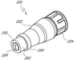
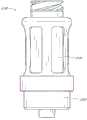
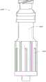
图2A为阀或无针型连接器的一个实施例的近端透视图;Figure 2A is a proximal perspective view of one embodiment of a valve or needleless connector;
图2B为图2A所示的连接器实施例的远端透视图;Figure 2B is a distal perspective view of the connector embodiment shown in Figure 2A;
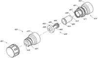
图3为图2A所示的连接器实施例的近端分解视图;Figure 3 is a proximal exploded view of the connector embodiment shown in Figure 2A;
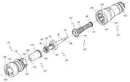
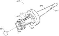
图4为图2A所示的连接器实施例的远端分解视图;Figure 4 is an exploded view of the distal end of the connector embodiment shown in Figure 2A;
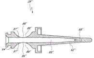
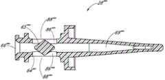
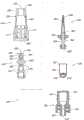
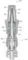
图4A为图2A所示的连接器实施例的沿其轴向中心线的分解剖视图;Figure 4A is an exploded cross-sectional view of the connector embodiment shown in Figure 2A along its axial centerline;
图5为图2A所示的连接器实施例的密封构件实施例的透视图;5 is a perspective view of an embodiment of a sealing member of the embodiment of the connector shown in FIG. 2A;
图6为图5所示的密封构件实施例的另一透视图;Figure 6 is another perspective view of the sealing member embodiment shown in Figure 5;
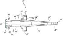
图7为图2A所示的连接器实施例的支撑构件实施例的近端透视图;7 is a proximal perspective view of the support member embodiment of the connector embodiment shown in FIG. 2A;
图8为图7所示的支撑构件实施例的远端透视图;Figure 8 is a distal perspective view of the embodiment of the support member shown in Figure 7;
图9为图7所示的支撑构件实施例沿其轴向中心线的剖视图;Fig. 9 is a cross-sectional view of the embodiment of the support member shown in Fig. 7 along its axial centerline;
图10为图2A所示的连接器实施例的调节器实施例的近端透视图;10 is a proximal perspective view of the regulator embodiment of the connector embodiment shown in FIG. 2A;
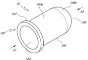
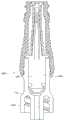
图11为图10所示的调节器实施例的远端透视图;Figure 11 is a distal perspective view of the regulator embodiment shown in Figure 10;
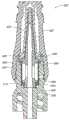
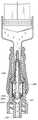
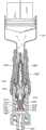
图12为图10所示的调节器实施例沿其轴向中心线的剖视图;Fig. 12 is a cross-sectional view of the regulator embodiment shown in Fig. 10 along its axial centerline;
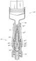
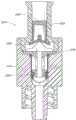
图13为图2A所示的连接器实施例的剖视图,其展示了在密封构件由医用器具(例如所阐述的注射器的例子)接触和打开之前、处于第一或封闭位置的密封构件;Figure 13 is a cross-sectional view of the embodiment of the connector shown in Figure 2A, showing the sealing member in a first or closed position prior to contact and opening by a medical implement, such as the illustrated syringe example;
图14为图2A所示的连接器实施例的剖视图,其展示了在密封构件由注射器接触和打开之后、处于第二或打开位置的密封构件;Figure 14 is a cross-sectional view of the connector embodiment shown in Figure 2A, showing the sealing member in a second or open position after the sealing member has been contacted and opened by the syringe;
图15为图2A所示的连接器实施例的示意图,该连接器用于将流体注入患者臂部的血液流中;15 is a schematic illustration of the embodiment of the connector shown in FIG. 2A for injecting fluid into the blood stream of a patient's arm;
图16为图2A所示的连接器实施例的剖视图,其展示了处于打开位置的密封构件,以及推进至注射器底部表面的活塞;16 is a cross-sectional view of the embodiment of the connector shown in FIG. 2A, showing the sealing member in an open position, and the plunger advanced to the bottom surface of the syringe;
图17为图2A所示的连接器实施例的剖视图,其展示了处于打开位置的密封构件,以及注射器的活塞从注射器的底部表面上反弹后的注射器;17 is a cross-sectional view of the connector embodiment shown in FIG. 2A, showing the sealing member in an open position, and the syringe after the plunger of the syringe has rebounded from the bottom surface of the syringe;
图17A为图2A所示的连接器实施例的剖视图,其展示了当注射器从连接器上移除之后、处于第一位置的密封构件;17A is a cross-sectional view of the embodiment of the connector shown in FIG. 2A, showing the sealing member in a first position after the syringe is removed from the connector;
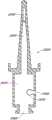
图18为支撑构件的另一实施例的近端透视图,该支撑构件可与图2A所示的连接器或在此公开的任意其它连接器一起使用;18 is a proximal perspective view of another embodiment of a support member that may be used with the connector shown in FIG. 2A or any other connector disclosed herein;
图19为图18所示的支撑构件实施例的远端透视图;Figure 19 is a distal perspective view of the embodiment of the support member shown in Figure 18;
图20为图18所示的支撑构件实施例沿其轴向中心线的剖视图;Figure 20 is a cross-sectional view of the embodiment of the support member shown in Figure 18 along its axial centerline;
图21为密封构件的另一实施例的近端透视图,该密封构件可与图2A所示的连接器或在此公开的任意其它连接器一起使用;21 is a proximal perspective view of another embodiment of a sealing member that may be used with the connector shown in FIG. 2A or any other connector disclosed herein;
图22为图21所示的密封构件实施例的远端透视图;Figure 22 is a distal perspective view of the sealing member embodiment shown in Figure 21;
图23为密封构件的另一实施例的近端透视图,该密封构件可与图2A所示的连接器或在此公开的任意其它连接器一起使用;23 is a proximal perspective view of another embodiment of a sealing member that may be used with the connector shown in FIG. 2A or any other connector disclosed herein;
图24为图23所示的密封构件实施例的远端透视图;24 is a distal perspective view of the sealing member embodiment shown in FIG. 23;
图25A为密封构件的另一实施例的近端透视图,该密封构件可与图2A所示的连接器或在此公开的任意其它连接器一起使用;25A is a proximal perspective view of another embodiment of a sealing member that may be used with the connector shown in FIG. 2A or any other connector disclosed herein;
图25B为图25所示的密封构件实施例的远端透视图;25B is a distal perspective view of the sealing member embodiment shown in FIG. 25;
图26A为支撑构件的另一实施例的透视图,该支撑构件可与图2A所示的连接器或在此公开的任意其它连接器一起使用;26A is a perspective view of another embodiment of a support member that may be used with the connector shown in FIG. 2A or any other connector disclosed herein;
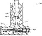
图26B为图26A所示的支撑构件实施例的剖视图;Figure 26B is a cross-sectional view of the embodiment of the support member shown in Figure 26A;
图26C为包括图26A所示的支撑构件实施例的连接器的剖视图;26C is a cross-sectional view of a connector including the support member embodiment shown in FIG. 26A;
图26D为支撑构件的另一实施例的剖视图,该支撑构件可与图2A所示的连接器或在此公开的任意其它连接器一起使用;26D is a cross-sectional view of another embodiment of a support member that may be used with the connector shown in FIG. 2A or any other connector disclosed herein;
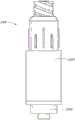
图27为阀或无针型连接器的另一实施例的近端透视图;27 is a proximal perspective view of another embodiment of a valve or needleless connector;
图28为图27所示的连接器实施例的远端透视图;Figure 28 is a distal perspective view of the connector embodiment shown in Figure 27;
图29为图27所示的连接器实施例的近端分解视图;Figure 29 is a proximal exploded view of the connector embodiment shown in Figure 27;
图30为图27所示的连接器实施例的远端分解视图;Figure 30 is a distal exploded view of the connector embodiment shown in Figure 27;
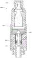
图31为图27所示的连接器实施例的剖视图,其展示了在密封构件由注射器接触和打开之前、处于第一或封闭位置的密封构件;Figure 31 is a cross-sectional view of the connector embodiment shown in Figure 27, showing the sealing member in a first or closed position prior to contact and opening of the sealing member by the syringe;
图32为图27所示的连接器实施例的剖视图,其展示了在密封构件由注射器接触和打开之后、处于第一或打开位置的密封构件;32 is a cross-sectional view of the connector embodiment shown in FIG. 27 showing the sealing member in a first or open position after the sealing member has been contacted and opened by the syringe;
图33为连接器的另一实施例的远端分解透视图;Figure 33 is an exploded perspective view of the distal end of another embodiment of the connector;
图34为图33所示的连接器实施例沿其轴向中心线的分解剖视图;Figure 34 is an exploded sectional view of the connector embodiment shown in Figure 33 along its axial centerline;
图35为图33所示的连接器实施例的密封构件沿其轴向中心线的的剖视图,其中密封构件处于第二或打开位置;Figure 35 is a cross-sectional view of the sealing member of the embodiment of the connector shown in Figure 33 along its axial centerline, wherein the sealing member is in a second or open position;
图36为阀或无针型连接器的另一实施例的近端透视图;36 is a proximal perspective view of another embodiment of a valve or needleless connector;
图37为图36所示的连接器的远端透视图;Figure 37 is a distal perspective view of the connector shown in Figure 36;
图38为图36所示的连接器的近端分解透视图;Figure 38 is a proximal exploded perspective view of the connector shown in Figure 36;
图39为图36所示的连接器的远端分解透视图;Figure 39 is an exploded perspective view of the distal end of the connector shown in Figure 36;
图40为图36所示的连接器沿其轴向中心线的分解剖视图;Figure 40 is an exploded sectional view of the connector shown in Figure 36 along its axial centerline;
图41为图36所示的连接器和处于未接合形态的附加无针型连接器的剖视图;Figure 41 is a cross-sectional view of the connector shown in Figure 36 and an additional needleless connector in an unengaged configuration;
图42为图36所示的连接器和处于接合形态的、图41所示的附加连接器的剖视图;Figure 42 is a cross-sectional view of the connector shown in Figure 36 and the additional connector shown in Figure 41 in an engaged configuration;
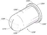
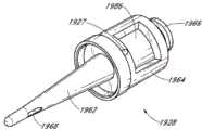
图43为动态容积调整器的实施例的远端剖视图;Figure 43 is a distal cross-sectional view of an embodiment of a dynamic volume adjuster;
图44为图43所示的动态容积调整器沿其轴向中心线的剖视图;Figure 44 is a sectional view of the dynamic volume adjuster shown in Figure 43 along its axial centerline;
图45为包括图43所示的动态容积调整器的阀或无针型连接器的剖视图;45 is a cross-sectional view of a valve or needleless connector including the dynamic volume adjuster shown in FIG. 43;
图46为阀构件的实施例的远端透视图;Figure 46 is a distal perspective view of an embodiment of a valve member;
图47为图45所示的阀构件沿其轴向中心线的剖视图;Figure 47 is a sectional view of the valve member shown in Figure 45 along its axial centerline;
图48为包括图46所示的动态容积调整器的阀或无针型连接器的剖视图;48 is a cross-sectional view of a valve or needleless connector including the dynamic volume adjuster shown in FIG. 46;
图49为同时包括图43所示的动态容积调整器以及图46所示的阀构件的阀或无针型连接器的剖视图;49 is a cross-sectional view of a valve or needleless connector including both the dynamic volume adjuster shown in FIG. 43 and the valve member shown in FIG. 46;
图50A为基座构件的实施例的剖视图;Figure 50A is a cross-sectional view of an embodiment of a base member;
图50B为包括图50A所示的基座构件的阀或无针型连接器的剖视图;50B is a cross-sectional view of a valve or needleless connector including the base member shown in FIG. 50A;
图51为具有单缝的调节器实施例的远端透视图;Figure 51 is a distal perspective view of an embodiment of an adjuster with a single slit;
图52为具有五个缝的调节器实施例的远端透视图;Figure 52 is a distal perspective view of an embodiment of an adjuster having five slits;
图53为调节器的另一实施例的远端透视图;Figure 53 is a distal perspective view of another embodiment of an adjuster;
图54为图53所示的调节器沿其轴向中心线、在第一方向上的剖视图;Fig. 54 is a cross-sectional view of the regulator shown in Fig. 53 along its axial centerline and in a first direction;
图55为图53所示的调节器沿其轴向中心线、在第二方向上的剖视图;Figure 55 is a cross-sectional view of the regulator shown in Figure 53 along its axial centerline and in a second direction;
图56为阀构件的另一实施例的远端透视图;Figure 56 is a distal perspective view of another embodiment of a valve member;
图57为包括图56所示的阀构件的、处于闭合形态的阀或医用连接器的剖视图;Figure 57 is a cross-sectional view of a valve or medical connector in a closed configuration including the valve member shown in Figure 56;
图58为图57所示的连接器的另一剖视图,其中阀构件处于打开形态;Figure 58 is another cross-sectional view of the connector shown in Figure 57, wherein the valve member is in an open configuration;
图59为调节器的另一实施例的远端透视图;Figure 59 is a distal perspective view of another embodiment of an adjuster;
图60为图59所示的调节器沿其轴向中心线的剖视图;Figure 60 is a sectional view of the regulator shown in Figure 59 along its axial centerline;
图61为包括图59所示的调节器的、处于闭合形态的阀或无针型连接器的剖视图;61 is a cross-sectional view of a valve or needleless connector in a closed configuration including the regulator shown in FIG. 59;
图62为图61所示的连接器的另一剖视图,其中调节器处于打开形态;Figure 62 is another cross-sectional view of the connector shown in Figure 61, with the regulator in an open configuration;
图63为调节器的另一实施例的近端透视图;Figure 63 is a proximal perspective view of another embodiment of an adjuster;
图64为包括图63所示的调节器的、处于闭合形态的阀或无针型连接器的剖视图;64 is a cross-sectional view of a valve or needleless connector in a closed configuration including the regulator shown in FIG. 63;
图65为图64所示的连接器的另一剖视图,其中调节器处于第一打开形态;Figure 65 is another cross-sectional view of the connector shown in Figure 64, with the adjuster in a first open configuration;
图66为图64所示的连接器的另一剖视图,其中调节器处于第二打开形态;Figure 66 is another cross-sectional view of the connector shown in Figure 64 with the adjuster in a second open configuration;
图67为调节器的另一实施例的远端透视图;Figure 67 is a distal perspective view of another embodiment of an adjuster;
图68为图67所示的调节器沿其轴向中心线的剖视图;Figure 68 is a cross-sectional view of the regulator shown in Figure 67 along its axial centerline;
图69为包括图67所示的调节器的、处于闭合形态的阀或无针型连接器;Figure 69 is a valve or needleless connector in a closed configuration including the regulator shown in Figure 67;
图70为图69所示的连接器的局部剖视图,其中调节器处于第一打开形态;Figure 70 is a partial cross-sectional view of the connector shown in Figure 69 with the adjuster in a first open configuration;
图71为图69所示的连接器的另一幅局部剖视图,其中调节器处于第二打开形态;Fig. 71 is another partial cross-sectional view of the connector shown in Fig. 69 with the adjuster in a second open configuration;
图72为阀或无针型连接器支撑构件的另一实施例的剖视图;72 is a cross-sectional view of another embodiment of a valve or needleless connector support member;
图73为支撑构件的另一实施例的近端透视图;Figure 73 is a proximal perspective view of another embodiment of a support member;
图74为包括图73所示的支撑构件的阀或无针型连接器的剖视图;74 is a cross-sectional view of a valve or needleless connector including the support member shown in FIG. 73;
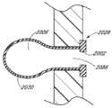
图75为包括袋状构件的支撑构件另一实施例的剖视图;75 is a cross-sectional view of another embodiment of a support member including a pocket member;
图76为图75所示的支撑构件的局部剖视图,其中袋状构件处于近似塌缩形态;Figure 76 is a partial cross-sectional view of the support member shown in Figure 75, wherein the pocket member is in an approximately collapsed configuration;
图77为图75所示的支撑构件的另一幅局部剖视图,其中袋状构件处于扩张形态;Figure 77 is another partial cross-sectional view of the support member shown in Figure 75, wherein the bag member is in an expanded configuration;
图78为阀或无针型连接器的另一实施例的侧视图;Figure 78 is a side view of another embodiment of a valve or needleless connector;
图79为图78所示的连接器沿其轴向中心线的的剖视图;Figure 79 is a sectional view of the connector shown in Figure 78 along its axial centerline;
图80为阀或无针型连接器的另一实施例的侧视图;Figure 80 is a side view of another embodiment of a valve or needleless connector;
图81为图80所示的连接器沿其轴向中心线的剖视图;Figure 81 is a sectional view of the connector shown in Figure 80 along its axial centerline;
图82为阀或无针型连接器的另一实施例的侧视图;Figure 82 is a side view of another embodiment of a valve or needleless connector;
图83为图82所示的连接器沿其轴向中心线的剖视图;Figure 83 is a sectional view of the connector shown in Figure 82 along its axial centerline;
图84为阀或无针型连接器的另一实施例的侧视图;Figure 84 is a side view of another embodiment of a valve or needleless connector;
图85为图84所示连接器沿其轴向中心线的剖视图;Figure 85 is a sectional view of the connector shown in Figure 84 along its axial centerline;
图86A为阀或无针型连接器的另一实施例的侧视图;Figure 86A is a side view of another embodiment of a valve or needleless connector;
图86B为图86A所示的连接器沿其轴向中心线的剖视图;Figure 86B is a cross-sectional view of the connector shown in Figure 86A along its axial centerline;
图87A为阀或无针型连接器的另一实施例的侧视图;Figure 87A is a side view of another embodiment of a valve or needleless connector;
图87B为图87A所示的连接器沿其轴向中心线的剖视图;Figure 87B is a sectional view of the connector shown in Figure 87A along its axial centerline;
图88A为阀或无针型连接器的另一实施例的侧视图;Figure 88A is a side view of another embodiment of a valve or needleless connector;
图88B为图88A所示的连接器沿其轴向中心线的剖视图;Figure 88B is a cross-sectional view of the connector shown in Figure 88A along its axial centerline;
图89A为阀或无针型连接器的另一实施例的侧视图;Figure 89A is a side view of another embodiment of a valve or needleless connector;
图89B为图89A所示的连接器沿其轴向中心线的剖视图;Figure 89B is a cross-sectional view of the connector shown in Figure 89A along its axial centerline;
图90A为阀或无针型连接器的另一实施例的侧视图;Figure 90A is a side view of another embodiment of a valve or needleless connector;
图90B为图90A所示的连接器沿其轴向中心线的剖视图;Figure 90B is a sectional view of the connector shown in Figure 90A along its axial centerline;
图91A为阀或无针型连接器的另一实施例的侧视图;Figure 91A is a side view of another embodiment of a valve or needleless connector;
图91B为图91A所示的连接器沿其轴向中心线的剖视图。Figure 91B is a cross-sectional view of the connector shown in Figure 91A along its axial centerline.
具体实施方式Detailed ways
以下针对本公开的具体实施例进行详细描述。在描述中,说明书通篇以及附图中相同的附图标记表示同一部件。Specific embodiments of the present disclosure are described in detail below. In the description, like reference numerals refer to like parts throughout the specification and in the drawings.
在所描述的实施例的一些方面中,描述了各种用于闭合连接器的一个或多个端部的装置。这些闭合机构可用于在闭合机构或阀处于封闭位置时基本防止和/或基本阻碍流体流经连接器的端部。当闭合机构处于打开位置时,例如当连接器与无针型注射器或其它医用连接器相接合时,允许流体流经连接器的一个或多个端部。在此所用的术语、例如“闭合”或“密封”及各种变形应当理解为,是指对流体流的障碍或阻碍。不应当将这些术语理解为是需要特定结构或形态来实现在所有情况下的完全性流体封闭。In some aspects of the described embodiments, various means for closing one or more ends of a connector are described. These closure mechanisms may be used to substantially prevent and/or substantially impede fluid flow through the ends of the connector when the closure mechanism or valve is in the closed position. When the closure mechanism is in the open position, eg, when the connector is engaged with a needle-free syringe or other medical connector, fluid is allowed to flow through one or more ends of the connector. Terms used herein, such as "closed" or "sealed" and variations thereof, should be understood to mean an obstruction or impediment to fluid flow. These terms should not be interpreted as requiring a particular structure or morphology to achieve a complete fluid seal in all cases.
在所公开的实施例的一些方面中,展示了用于控制连接器内的流体流的各种装置。这些流体控制阀或机构能协助控制潜在的、不希望产生的流入或流出连接器的流体运动。例如,可能希望防止、阻碍或减少进入连接器的负流或流体。在此所使用的负流、倒退流、回流、进入流以及相关术语与其在医用连接器领域的惯常含义相一致。在一些情况下,这些术语是指由以下情况所引起的流体流入连接器的情形:由于连接器内流体空间的内部容积的增加或有效增加、或由于流体从外部吸出或移除(例如通过撤去原先插入在连接器中的一部分医用器具)、或由于在大致倒退方向上的流体压力的外力,例如由于患者咳嗽、患者血压升高或流体源的不稳定(例如,输液袋流体量的减少或“干涸”)等引起。负流量通常在与预期流体流大致相对或相反的方向上产生。In some aspects of the disclosed embodiments, various means for controlling fluid flow within a connector are presented. These fluid control valves or mechanisms can assist in controlling potential undesired fluid movement into or out of the connector. For example, it may be desirable to prevent, impede, or reduce negative flow or fluid entering the connector. Negative flow, reverse flow, return flow, incoming flow, and related terms are used herein in accordance with their conventional meanings in the field of medical connectors. In some contexts, these terms refer to the inflow of fluid into a connector as a result of an increase or effective increase in the internal volume of the fluid space within the connector, or as a result of fluid being sucked or removed from the outside (such as by withdrawing A portion of a medical implement that was originally inserted in the connector), or external forces due to fluid pressure in a generally reversed direction, such as due to patient coughing, elevated patient blood pressure, or instability of the fluid source (e.g., a decrease in fluid volume in an infusion bag or "dry up") and so on. Negative flow generally occurs in a direction generally opposite or opposite to intended fluid flow.
在此所用的术语“中性的”、“中性位移”、“中性流”以及其它相关术语与其在医用连接器领域的惯常含义是一致的。在一些情况下,这些术语涉及这样的医用连接器或阀:这些医用连接器或阀通常在需要使用特定连接器或阀的大多数临床条件下不会产生负流,或者在需要使用特定连接器或阀的大多数临床条件下产生极低水平的负流、从而使得对患者造成损害的风险或者由负流导致的需要更换连接器、阀或导管的可能性变得非常地低。另外,中性连接器或阀一般不产生具有临床显著意义的、从连接器或阀的远端到连接器或阀的近端的流体流,这种流体流是基于另一医用器具与连接器或阀的远端的连接或断开而自动产生的。在所公开的一些实施例中,连接器或阀可以是中性的、或可获得中性流。The terms "neutral," "neutral displacement," "neutral flow," and other related terms used herein are consistent with their conventional meanings in the field of medical connectors. In some contexts, these terms refer to medical connectors or valves that generally do not produce negative flow in most clinical conditions that require the use of a particular connector or valve, or that Most clinical conditions with valves or valves produce extremely low levels of negative flow such that the risk of harm to the patient or the need for replacement of a connector, valve or catheter due to negative flow is very low. In addition, neutral connectors or valves generally do not produce clinically significant fluid flow from the distal end of the connector or valve to the proximal end of the connector or valve based on another medical device and the connector. or the connection or disconnection of the distal end of the valve is automatically generated. In some disclosed embodiments, the connector or valve can be neutral, or have access to neutral flow.
负流具有许多种源,包括当医用器具、例如注射器从连接器的近端(在此称连接器的第一端或母端)移除时所产生的负流。随着注射器的移除,连接器内的流体保持空间可能会增大。当该流体空间与患者的流体线导管相通时,连接器内的流体空间的增加可能回将流体从导管从远端吸入连接器中,连接器的远端在此称第二端或公端。这可能是不利的,因为这种负流可因此将血液从患者身体中吸入导管的相对端。而流体线中的这种血液可能会凝块或玷污流体线,从而很可能需要过早更换并再次插入导管线、连接器以及其它医用器具。Negative flow has many sources, including negative flow created when a medical implement, such as a syringe, is removed from the proximal end of the connector (referred to herein as the first or female end of the connector). As the syringe is removed, the fluid holding space within the connector may increase. When this fluid space communicates with the patient's fluid line conduit, the increase in fluid space within the connector may draw fluid from the conduit into the connector from the distal end, referred to herein as the second or male end. This may be disadvantageous since such negative flow may thus draw blood from the patient's body into the opposite end of the catheter. This blood in the fluid line may clot or contaminate the fluid line, likely requiring premature replacement and reinsertion of catheter lines, connectors, and other medical implements.
负流还可来源于连接至连接器近端的器具。这种类型的负流的一个例子是,由泵机或手动注射器引起的负流。例如,当连接至连接器的医用器具为注射器时,其通常包括连接器活塞的弹性活塞头,用于由用户或机器进行按压。当注射器内的流体排出后,可朝注射器内腔的端部压缩活塞。在松开活塞壁上的压力后,压缩活塞头通常会反弹,或在远离连接器内腔端部的近端方向上轻微地扩张。在腔的端部与活塞头的远端表面之间可能会由此形成小的真空。由于注射器和连接患者的导管仍是流体相通的,因此,所述真空可能会被来自连接器的流体填充,而这又会将流体从导管拉入连接器中。这种流体的倒回能引起凝块或玷污导管线。Negative flow can also originate from an appliance connected to the proximal end of the connector. An example of this type of negative flow is that caused by a pump or manual syringe. For example, when the medical implement connected to the connector is a syringe, it typically includes a resilient plunger head of the connector plunger for depression by a user or machine. After the syringe has been expelled, the plunger can be compressed towards the end of the syringe lumen. After the pressure on the piston wall is released, the compression piston head typically rebounds, or expands slightly, in a proximal direction away from the end of the connector lumen. A small vacuum may thus form between the end of the cavity and the distal surface of the piston head. Since the syringe and the tubing connected to the patient are still in fluid communication, the vacuum may be filled with fluid from the connector, which in turn pulls fluid from the tubing into the connector. This backflow of fluid can cause clots or contaminate the catheter line.
在使用中负流可以通过其它方式产生,例如当用于通过导管注入流体的输液袋变干、患者血压变化或患者身体移动时等。负流还可由流体流的动量产生。注射器或机器可将流体注入连接器中。使用者或机器通常将尽可能多的流体推进连接器中,例如通过将活塞头按压至注射器内腔的端部。甚至在活塞上的压力释放之前,连接器内也可能产生一些负流。流体分子由分子间作用力相连,并具有动量。随着最后量的流体离开流体源,流体被推出连接器以及导管。随着在远端方向上推动流体的力的结束,导管端部的流体继续流出导管,而来自导管端部的进一步的流体仍留在导管中。导管端部与导管内流体柱的端部之间的真空可被血液填充,而这将导致凝块。Negative flow can be produced by other means in use, for example when the infusion bag used to infuse fluid through the catheter dries out, when the patient's blood pressure changes, or when the patient's body moves, etc. Negative flow can also be created by the momentum of the fluid flow. A syringe or machine injects fluid into the connector. The user or machine typically pushes as much fluid as possible into the connector, for example by pressing the plunger head against the end of the syringe lumen. There may be some negative flow in the connector even before the pressure on the piston is released. Fluid molecules are connected by intermolecular forces and have momentum. As the last amount of fluid exits the fluid source, the fluid is pushed out of the connector and conduit. As the force pushing the fluid in the distal direction ends, fluid from the catheter end continues to flow out of the catheter while further fluid from the catheter end remains in the catheter. The vacuum between the end of the catheter and the end of the fluid column within the catheter can be filled with blood, which can lead to clots.
本发明的一些实施例可大致消除、减少、最小化或控制一些或全部负流源的影响。尽管在此所公开的一些实施例的运作是结合单一负流源(例如,注射器反弹)进行讨论的,然而应当理解,可用类似或相同方式对许多负流源进行消除、减少、使最小化或控制。Some embodiments of the invention may substantially eliminate, reduce, minimize, or control the effects of some or all negative flow sources. Although the operation of some embodiments disclosed herein is discussed in connection with a single source of negative flow (e.g., syringe bounce), it should be understood that many sources of negative flow can be eliminated, reduced, minimized, or control.
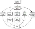
图1展示了可包含于在此公开的无针型连接器的一些实施例中的各种不同部件和配置。图1不应当解释为是阐释能够使用的全部可能的组合和/或部件。一些实施例可包括近端、近端封闭系统、内部封闭系统和远端,这些部件彼此相连地设置,如位于图1左侧的第一串方框所示。一些实施例可包括近端、近端封闭系统、容积调整器、内部封闭系统和远端,这些部件彼此相连地设置,如位于图1中第二串方框所示。一些实施例可包括近端、近端封闭系统、内部封闭系统、容积调整器和远端,这些部件彼此相连地设置,如位于图1中第三串方框所示。一些实施例可包括近端、近端封闭系统、容积调整器和远端,这些部件彼此相连地设置,如位于图1中第四串方框所示。一些实施例可包括近端、近端封闭系统、组合式内部封闭系统与容积调整器、以及远端,这些部件彼此相连地设置,如位于图1中第五串方框所示。这些部件中的任意一个在特定实施例中都可省略,且彼此相连设置的所示部件之间还可包括其它部件。FIG. 1 illustrates various components and configurations that may be included in some embodiments of the needleless connectors disclosed herein. Figure 1 should not be interpreted as illustrating all possible combinations and/or components that could be used. Some embodiments may include a proximal end, a proximal closure system, an inner closure system, and a distal end, which are arranged adjacent to each other, as shown in the first series of boxes on the left side of FIG. 1 . Some embodiments may include a proximal end, a proximal closure system, a volume adjuster, an inner closure system, and a distal end, which are arranged in connection with each other, as shown in the second series of boxes in FIG. 1 . Some embodiments may include a proximal end, a proximal closure system, an inner closure system, a volume adjuster, and a distal end, which are arranged in connection with each other, as shown in the third series of boxes in FIG. 1 . Some embodiments may include a proximal end, a proximal closure system, a volume adjuster, and a distal end, which are arranged in connection with each other, as shown in the fourth series of blocks in FIG. 1 . Some embodiments may include a proximal end, a proximal closure system, a combined inner closure system and volume adjuster, and a distal end, all of which are connected to each other, as shown in the fifth series of blocks in FIG. 1 . Any of these components may be omitted in a particular embodiment, and other components may also be included between shown components that are disposed in conjunction with one another.
可使用许多其它组合和其它类型的部件来替代或添加于图1所示的配置中。例如,一些实施例可包括近端、组合式近端封闭系统和容积调整器和/或组合式近端封闭系统和内部封闭系统,以及远端。在一些实施例中,可具有多组图1所示的部件。例如,可在内部封闭系统的两侧设置一对容积调整器。在一些实施例中,远端可包括封闭系统。在此所阐释或描述的任何部件、特征或步骤都可在一些实施例中加以省略。没有一个部件、特征或步骤是必需的或必不可少的。Many other combinations and other types of components may be used instead of or in addition to the configuration shown in FIG. 1 . For example, some embodiments may include a proximal end, a combined proximal closure system and volume adjuster and/or a combined proximal and inner closure system, and a distal end. In some embodiments, there may be multiple sets of components shown in FIG. 1 . For example, a pair of volume adjusters may be provided on either side of the internal closure system. In some embodiments, the distal end can include a closure system. Any component, feature or step illustrated or described herein may be omitted in some embodiments. No single component, feature or step is required or essential.
阐释了近端封闭系统的数个实施例,包括密封构件26和支撑构件28(例如见图3)、密封构件26’(例如见图21)、密封构件26’’( 例如见图23)、密封构件326(例如见图34)、帽491(例如见图38),以及密封构件2126、2226、2326、2426、2526、2626、2726、2826、2926和3026(例如见图79、81、83、85、86B、87B、88B、89B、90B和91B)。还可使用其它类型的近端封闭系统。每个实施例的近端封闭系统可与经适当修正的其它实施例中的近端封闭系统相互替换(在需要时)。一些实施例中还可省略近端封闭系统。Several embodiments of proximal closure systems are illustrated, including sealing
阐释了容积调整器的数个实施例,包括容积调整器30、330、630、1030、1130、1230、1430、1530、1730、1930、2130、2230、2330、2430、2530、2630、2730、2830、2930和3030(例如见图10-12、34、43-44、51-53、59-60、63、67-68、74、79、81、83、85、86B、87B、88B、89B、90B和91B)、气球构件1830(例如见图72)以及袋状2030(例如见图75-77)。还可使用其它类型的容积调整器,包括在此所示和/或所述的其它容积调整器。每个实施例的容积调整器可与经适当修正的其它实施例中的容积调整器相互替换(在需要时)。一些实施例中还可省略容积调整器。Several embodiments of volume adjusters are illustrated, including
阐释了内部封闭系统的数个实施例,包括阀构件108、308、408、730、1008、1108、1208、1330、1408、1508和1708(例如见图10-12、34、40、46-47、51-53、57、59-60、63和67-68),以及展示于图79、81、83、85、86B、87B、88B、89B、90B和91B中的相似阀构件。还可使用其它类型的内部封闭系统,包括在此所示和/或所述的其它内部封闭系统。每个实施例的内部封闭系统可与经适当修正的其它实施例中的内部封闭系统相互替换(在需要时)。一些实施例中还可省略内部封闭系统。Several embodiments of internal closure systems are illustrated, including
图2A和图2B分别为阀或无针型连接器20的一个实施例的透视图。图3和图4为图2A所示的连接器20的实施例的分解视图。图4A为图2A所示的连接器20的分解剖视图。参见图2A到图4A,无针型连接器20一些实施例可特别包括主体构件22、基座构件24、密封构件26、支撑构件28和调节器30。2A and 2B are perspective views of one embodiment of a valve or
在所示实施例中, 主体构件22和基座构件24可组装在一起,以形成大致封闭密封构件26(以下称第一阀构件)、支撑构件28和调节器30的壳体。主体构件22和基座构件24可用粘合剂、塑性或声波焊接、卡口机构、干扰机构或压扣机构连接在一起,或通过使用其它任何适当特征或方法相连。在一些实施例中,主体构件22和基座构件24可使用为大致三角形的声波焊接连接在一起,当然其它形状也是适合的。In the illustrated embodiment, the
主体构件22、基座构件24、支撑构件28以及连接器20的其它任何部分或特征都可由若干适当材料中的任意一种制成。例如,主体构件22、基座构件24、支撑构件28以及连接器20的其它任何部分或特征可由相对刚性的材料制成,例如聚碳酸脂、玻璃填充 GE Valox 420、聚丙烯或其它聚合材料。主体构件22、基座构件24、支撑构件28以及连接器20的其它任何部分或特征还可由疏水性材料制成,例如Bayer Makrolon或其它任何类似或适当材料。在此所公开的连接器20及其它连接器的一个或多个部件可包括任何适当形式的合适的抗微生物因子,例如作为成分矩阵一部分的成分覆膜,或其它适当形式。在一些实施例中,所述抗微生物因子在使用中或随时间而从一个或多个成分中分离。在一些实施例中,所述抗微生物剂可包含银离子。
如上所述,支撑构件28可由与形成主体构件22或基座构件24相同类型的刚性材料形成。在一些实施例中,例如,支撑构件28可由半刚性或甚至比主体构件22、基座构件24或连接器20的其它部件所用材料更柔软的材料形成。在一些实施例中,支撑构件28(以及在此公开的任何其它连接器的支撑构件的任何其它实施例)可与基座构件24(以及在此公开的任何其它连接器的基座构件的任何其它实施例)一体式形成,或可单独形成,再与基座构件相接合。As noted above, the
在一些实施例中,主体构件22可包括一个或多个大致沿连接器20的纵向方向延伸的凹部或槽41,以协助密封构件26的移动。该槽41可提供用于使密封构件26塌缩进入其中的区域,并能减少当密封构件26在壳体内移动时与密封构件26接触的表面区域。In some embodiments,
图5和图6为图2A所示的连接器20中的密封构件26实施例的透视图。参见图1到6,密封构件26可设置为使得密封构件26的近端部分34由主体构件22近端162的开口36密封地容纳。在一些实施例中,如图示实施例,密封构件26的近端部分34可具有形成于其上的唇形部分38(该唇形部分38为环形突出),用于接触主体构件22的开口36,以实现密封。密封构件26的远端53可包括开口54。在一些实施例中,支撑构件28可容纳与该开口54内。在一些实施例中,远端53进一步包括向外延伸的凸缘56,该凸缘56围绕或大致围绕密封构件26延伸。在一些实施例中,凸缘56可协助将密封构件26置于主体构件22的内部腔中。5 and 6 are perspective views of an embodiment of the sealing
术语“近端”在此指连接器20位于或靠近主体构件22端部的一端。术语“远端”在此指连接器相反的端部,即连接器20位于或靠近基座构件24端部的一端。在图示实施例中,近端设置为母端,而远端设置为公端。连接器20的任何端部、设置或方面可设置为适应任何标准的医用连接器或器具,并设置为遵循ANSI(American National Standards Institute, Washington, D.C.)或其它可适用标准。术语“医用器具”在此指普遍用于医疗领域的、可与在此所公开的连接器的任何实施例相连或相接合的任何医疗设备。所设想的医用器具的例子包括但不限于管子、鲁尔接头、导管、注射器、静脉注射装置(外周和中枢线的)、可封闭式公鲁尔连接器(与注射器一体式形成或作为独立的连接器)、泵、背负式线以及其它可用于连接医用阀或连接器的部件。The term "proximal end" herein refers to the end of the
密封构件26、密封构件26的近端部分34以及唇形部分38可一体式形成,或可单独形成,再通过粘合剂或其它适当材料或方法接合在一起。在一些实施例中,在此所公开的密封构件26或密封件、密封构件的其它任何实施例以及其部件或特征都可由许多不同的适当材料制成,包括硅基的可形变材料、橡胶、或其它适当材料。硅基可形变材料与塑料和其它刚性复合材料形成液密性封闭。
密封构件26或其它在此公开的任何密封构件可由一种、两种或多种不同材料形成。在一些实施例中,密封构件26的不同部分可由不同材料形成。例如,密封构件26可具有弹簧(未图示),以提供将密封构件26偏向至封闭位置所需的部分或全部回复力。弹簧可由金属(例如钢铁)、塑料或其它任何适当的刚性或柔性材料形成,并可形成密封构件26的核心,以便硅橡胶或其它柔性密封材料将弹簧封装入其中。在一些实施例中,密封构件26可仅由具有弹力的或弹性的材料制成。同样,通过举例方式,密封构件26可包括弹性主体部分和单独形成的弹性近端部分。这些单独件可彼此接合,例如通过连接至引导构件的方式,该引导构件具有用于连接至近端部分的第一端部和用于连接至主体部分的第二端部。该引导构件可由比主体部分和/或近端部分的材料硬度更大的材料制成。
密封构件26可具有尖细的弹性主体部分50,该弹性主体部分50具有大致褶形、大致波浪形、大致交错或大致波形轮廓的形状,以协助密封构件26在施加以及移去轴向力时的弹性压缩和扩张。在一些实施例中,主体部分50可包括一系列一体式形成或单独形成、再接合在一起的、大致为圆形或O形的结构,或一个或多个大致与压缩和扩张方向横向分布的槽结构。这些结构和形状的直径或横截面形状和/或大小都可有所不同。在一些实施例中,所述结构和形状可在近似垂直于密封构件26(例如,如图3到6所示)纵轴的方向上大致向内和向外交替延伸。这些结构和形状可以为多种形态,例如螺旋状形态。The sealing
在一些实施例中,主体部分50的内表面可大致匹配主体部分50的外表面,以使得主体部分50的内表面还可具有本申请其它处所述的结构或轮廓。在一些实施例中,主体部分50的内表面可大致径向地向内延伸,而主体部分50外表面的相应部分径向地向外延伸;主体部分50的内表面可大致径向地向外延伸,而主体部分50外表面的相应部分径向地向内延伸。因此,主体部分50可包括一系列凸部,其中主体部分50的壁的厚度在厚区段与薄区段之间交替,例如图4A所示。在一些实施例中,主体部分50的内表面可大致径向地向内延伸,而主体部分50外表面的相应部分大致径向地向内延伸;主体部分50的内表面可大致径向地向外延伸,而主体部分50外表面的相应部分径向地向外延伸。因此,主体部分50可包括一系列弯曲部段,其中主体部分50的壁具有更均匀的厚度。在一些实施例中,主体部分50的内表面可具有相对平滑或扁平的表面形状。In some embodiments, the inner surface of
主体部分50可具有沿其长度基本一致的横截面形状或大小,或主体部分50的横截面形状或大小可沿至少一部分长度而有所不同。在一些实施例中,主体部分50内部的形状可近似匹配支撑构件28的长形部分62的外表面。在一些实施例中,主体部分50包括大致为圆锥形的下部50a,以及大致为圆柱形的上部50b。还可作出多种变形。
密封构件26可设置为使得主体部分50偏向于初始或扩张位置,如图5所示。当轴向力作用于密封构件26时,可引起近端部分34和/或主体部分50被压缩至第二位置,并因此轴向地缩回,以缩短密封构件26的整体长度。当从密封构件26上移去该轴向力时,近端部分34和/或主体部分50可因偏压而再次延伸,以使密封构件26返回至其在第一或封闭位置的放松状态,密封构件26在该状态下仍可保持一定程度的压缩,以使得例如近端部分34的唇部38与主体构件22的内表面或表面在一定程度的轴向拉力下相接合。The sealing
密封构件26可设置为使得密封构件26的近端部分34容纳在主体构件22上的开口36中。在一些实施例中,如图示实施例,密封构件26的近端部分34可具有唇形部分38(该唇形部分38可为环形突出),设置该唇形部分38以使其接触主体构件22的开口36的内表面,从而提供密封,基本阻止颗粒物或流体进入连接器。The sealing
另外,如图5所示,密封构件26的近端部分34上可形成狭缝或开口52。密封构件26的狭缝52可偏向于封闭位置,以大致阻止或妨碍流体流经密封构件26上的狭缝52。另外,在一些实施例中,如以下将更详细描述的,可通过在远端方向上使密封构件26越过支撑构件28缩回而打开狭缝52,从而使支撑构件28的近端部分的至少一部分刺入并穿过狭缝52。在一些实施例中,狭缝52可设置为打开的,而无需经由支撑构件28刺入。Additionally, as shown in FIG. 5 , a slit or opening 52 may be formed in the
图7和图8为图2A所示的连接器20实施例中的支撑构件28实施例的透视图。图9为图7所示的支撑构件28实施例沿其轴向中心线的剖视图。参见图7到图9,在一些但非全部实施例中,支撑构件28可包括基座部分60、在近端方向上从基座部分60突出的长形部分62,以及在远端方向上从基座部分60突出的远端64。在一些实施例中,图示支撑构件28的一个或多个部件可省略,或由不同部件替代。例如,支撑构件无需包括长形部分62。在一些实施例中,支撑构件可大致更短,以便不延伸进、通过和/或靠近密封构件的近端。在连接器20的一些实施例中,根本没有支撑构件。密封构件可设置为无需刺入支撑构件、或根本无需支撑构件便能打开,例如当密封构件位于自然打开位置时(在该自然打开位置时由直径更小的壳体便能迫使其闭合),或当密封构件连接至壳体的近端区域时等。还可将调节器固定或置于壳体内,该调节器无需支撑构件便可运作。例如,在一些实施例中,调节器30可连接至密封构件和/或可与另一结构分开悬置,或调节器30可为未连接、自由浮动的,无需图13所示的远端64或内部支撑。7 and 8 are perspective views of an embodiment of
在一些实施例中,所示支撑构件28的一个或多个部件可单独形成,再通过粘合剂、声波焊接、卡扣配合或其它方式相互连接。例如,长形部分62和基座部分60可单独形成,再由例如声波焊接连在一起。在一些实施例中,整个支撑构件28可作为单件单元一体式形成。在一些实施例中,流体可流经连接器20腔内的一个或多个孔,例如位于或靠近腔的远端的孔,这些孔位于密封构件或其它流体障碍物的内部或外部。尽管是作为单一构件进行展示的,在一些实施例中,支撑构件28的部件也可单独形成。例如,长形部分62和/或其它任何部件可设置为使用中在连接器内移动。In some embodiments, one or more components of the illustrated
在一些实施例中,远端64可包括大致为圆柱形的外表面64a。远端64的纵向长度可大致小于长形部分62的纵向长度,如图所示。大致跨过远端64的横向截面的距离可小于大致跨过调节器30的横向截面的距离(例如见图12)。另外,在一些实施例中,开口66可轴向地穿过支撑构件28的至少一部分。在所示实施例中,开口66可与大致轴向地延伸穿过支撑构件28的流体通路69流体地连通。流体通路可延伸穿过远端64、基座部分60和长形部分62的大部分,以使得形成于长形部分62近端的一个或多个横向或径向开口68与开口66相通。In some embodiments,
如图7到9所示,长形部分62可具有尖细的外表面70和近端尖端部分72。该近端尖端部分72可具有大致尖细(或大致为圆锥形)的外表面,或可大致为圆柱形。长形部分62可设置为使得该近端尖端部分包括横截面区域,该横截面区域显著小于支撑构件28的基座部分60的横截面区域。在一些实施例中,近端尖端部分72可设置为使得密封构件26的近端部分34相对于支撑构件28的近端尖端部分72能够缩回(例如,从压缩位置到扩张或初始位置),而无需来自支撑构件28的明显的拽拉或阻挡。在一些实施例中,近端尖端部分72具有尖锐的或圆的尖端74,以刺穿形成于密封构件26上的狭缝52。在一些实施例中,尖端74与尖端部分72和长形部分62的其余部分一体式形成。在一些实施例中,长形部分62的近端包括位于其近端尖端的孔和通路69,该通路69可从开口66延伸至尖端的开口。As shown in FIGS. 7-9 , the
基座部分60可具有外部环形壁78,该外部环形壁78与支撑构件28的远端一起形成环形通道82。通道82可用于容纳密封构件26的远端部分56的一部分。在一些实施例中,基座部分60可用于使远端部分56相对于支撑构件28的基座部分60变得紧固,以防止远端部分56相对于基座部分60在远端轴向方向上移动。另外,通道82可用于使远端部分56相对于支撑构件28的基座部分60变得紧固,以防止远端部分56相对于基座部分60在径向方向上移动。密封构件26可与支撑构件28一起组装,密封构件26的远端部分56可固定至支撑构件28的基座部分60上,也可以不固定。事实上,在一些实施例中,密封构件26的远端可“浮动”在主体构件22的内腔中,并能随密封构件26从封闭位置向打开位置移动而轴向地移动。The
支撑构件28的远端部分64可具有一个或多个横向或径向地成的、穿过远端64的开口86。在图示实施例中,远端64上形成有两个开口86,并设置为大致矩形的槽,其长轴大致沿连接器的轴延伸。然而, 在一些实施例中,在远端64上能形成一个、三个、四个或多个开口,且这些开口可以是槽或其它形状的孔。在一些实施例中,一个或多个开口86可沿远端64的纵向长度的至少大部分而延伸,如图所示。可形成该一个或多个开口86,以与支撑构件28上形成的轴向开口66相通。The
大致为环形的腔或室88可位于支撑构件28的远端64上。环形腔88可位于两个环形突出90和92之间,而两个环形突出90和92位于远端64上。如以下将详细所叙述的,腔88可被流经位于支撑构件28上的开口66和86的流体所填充。环形突出94也可位于支撑构件28的远端部分,以使得环形突出90和94之间形成通道96。A generally annular cavity or
图10和11分别为图2A所示连接器的调节器30实施例的透视图。图12为图10所示的调节器30实施例沿调节器30轴向中心线的剖视图。如图10到12所示,调节器30可具有主体部分100和近端部分102。在一些实施例中,如图示实施例,主体100可以为近似圆柱形,而近端部分102可具有环形升高部分或唇部103以及穿过其的开口104。在一些实施例中,如图所示,连接器包括多个阀结构,例如密封构件26和调节器30,以控制流经和/或位于连接器20内的流体。10 and 11 are perspective views of an embodiment of an
在此所公开的调节器30或调节器、阀或阀构件的任何其它实施例以及其任何部件或特征都可由多种不同材料制成,包括硅基的可形变材料、橡胶或其它适当材料。硅基的可形变材料是那些可与塑料及其它刚性复合材料或金属材料形成流体密封闭合的材料之一。在一些实施例中,调节器30可以是有弹力的、弹性的和/或返回性的。在一些实施例中,调节器30可由与密封构件26相同的材料制成。如图示实施例所示,调剂器30的可变容积或动态调节器部分可具有非常薄的、极具弹力和/或柔顺性的一个或多个侧壁,所述侧壁在一些实施例中甚至薄于密封构件26的至少一部分或全部侧壁,以使调节器30对液压的变化高度敏感。The
另外,调节器30可包括位于远端部分108的阀构件,该阀构件具有形成于其上的一个或多个孔或狭缝110,图示实施例中为两个狭缝110。在一些实施例中,如图示实施例所示,端部108可包括具有近似拱形的、近似圆顶形的或近似球形形状的阀构件。远端部分108可设置为使得远端部分108偏向于封闭位置(例如,狭缝110偏向于闭合形态)。因此,在一些实施例中,当调节器30内的流体与作用在调节器30外表面的流体之间压力差的幅度低于预定水平时,远端部分108可设置为大致闭合,(例如,当作用在端部108内表面108a上的压力与作用在端部108外表面108b上的压力之差低于预定水平时)。Additionally, the
如图所示,随着阀构件远侧的流体压力升至特定水平,远端部分108上的阀构件的形状可使阀构件更紧密地闭合。在该流体压力阻力水平之外时,则阀构件可向内弯曲或移动(例如,在近端方向),以允许倒退流通过。可设置阀构件(例如,通过选择适当的形状、位置及所使用的材料),以使得该流体阻力水平大于通常因注射器反弹、近端鲁尔接头的移除和/或外部导致的负流(例如,患者咳嗽、打喷嚏、移动和血压升高或输液袋流体减少)所产生的压力差,但小于通常由从连接器20的近端有意识地移除流体而产生的压力差。在一些实施例中,如图所示,随着压力差的增加或朝其开启压力的积聚,阀构件可大致保持其初始形状,以避免或减少在低于开启压力的压力差时负流力通过阀构件而相通。As shown, the shape of the valve member on
在一些实施例中,倒退流或负流可由外部效应(这些外部效应有时来自连接器20的上游)引起,例如输液袋内流体液位的降低,和/或由患者或护理人员引起的流体线的波动或其它移动。当输液袋内的流体降至低液位或即将干涸时(或输液袋的位置相对于患者而言过低),则输液袋先前具有的水头压力也降低了。在一些实施例中,水头压力的这种下降可使流体线易受到因患者来回移动而引起的、连接器上游和下游的液体柱的“晃动”或改变运动的影响,从而产生周期性负流。在一些实施例中,内部或远端阀构件、例如位于调节器远端108的阀构件可设置为闭合,当来自输液袋中逐渐降低的流体液位的上游水头压力跌至阈值以下,而在该阈值点上可能开始晃动或改变流体运动。In some embodiments, backflow or negative flow may be caused by external effects (sometimes from upstream of connector 20), such as a drop in fluid level within an infusion bag, and/or fluid lines caused by the patient or caregiver. fluctuations or other movements. When the fluid in the bag drops low or runs dry (or the bag is positioned too low relative to the patient), the head pressure the bag previously had is also reduced. In some embodiments, this drop in head pressure can make the fluid line susceptible to "sloshing" or changing motion of the fluid column upstream and downstream of the connector as the patient moves back and forth, creating periodic negative flow . In some embodiments, an internal or distal valve member, such as the valve member located at the regulator
在一些实施例中,阀构件可为双稳态阀,该双稳态阀设置为在高于特定阈值的流体力的作用下在第一方向上打开(例如,在从近端到远端的方向上),该流体力作用在第一方向上,并保持为对在该方向上的流体液流打开,直到高于理想阈值的流体力作用在第二方向上(例如,在从远端到近端的方向上),该力导致阀打开,并保持对在第二方向上的流体打开。该双稳态阀可在第一方向上的、高于阈值的力的作用下再次从第二方向的液流切换回至第一方向。In some embodiments, the valve member may be a bistable valve configured to open in a first direction (eg, in a proximal-to-distal direction) under the action of a fluid force above a certain threshold. direction), the fluid force acts in a first direction and remains open to fluid flow in that direction until a fluid force above a desired threshold acts in a second direction (for example, in the direction from distal to proximal direction), the force causes the valve to open and remain open to fluid in the second direction. The bistable valve is switchable again from flow in the second direction back to the first direction under the action of a force in the first direction above a threshold value.
在一些实施例中,一个或多个狭缝110的宽度(由图12中的“WS”表示) 可以近似等于开口104(由图12中的“WO”表示)的宽度。在一些实施例中,如图示实施例中,一个或多个狭缝110的宽度WS可小于开口104的宽度。在一些实施例中,如图所示,宽度WS、或跨过可变容积室的横向截面距离的宽度可大致小于可变容积室的纵向长度,或大致小于整个调节器30的纵向长度。在一些实施例中,如图所示,调节器30在远端部分108的、位于至少一部分阀构件区域的壁的厚度可以大致大于调节器30在可变容积室或主体部分100的壁的厚度,以增强主体100的弹性、顺应性以及对阀构件引起的回流的阻挡性。在一些实施例中,如图所示,阀构件在远端部分108的纵向长度可以大致小于位于调节器30主体部分100的可变容积室的纵向长度(在二者的实施例中,这些部分是连接或分离的)。In some embodiments, the width of the one or more slits 110 (denoted by "WS" in FIG. 12 ) may be approximately equal to the width of the opening 104 (denoted by "WO" in FIG. 12 ). In some embodiments, such as the illustrated embodiment, the width WS of the one or
在一些实施例中,调节器30可设置为当调节器30内外的压力差达到第一幅度时,使调节器30的远端部分108打开,以允许流体在第一方向上流经调节器30(例如,在从近端102到封闭端或远端108的方向上,由图10中的箭头A1所示)。类似地,调节器30可设置为当调节器30内外的压力差达到第二幅度时,使调节器30的远端部分108打开,以允许流体在第二方向上流经调节器30(例如,在从封闭端或远端108到近端102的方向上,由图10中的箭头A2所示)。In some embodiments, the
位于内部或远端封闭系统的阀构件可具有许多不同的形状和设置。例如,在一些实施例中,阀构件及相关附件和定位结构可以与公布号为2010/0049157 A1的美国专利申请的图50到56、第309到325段所阐释的阀2200和2250相同或类似,该申请所公开的全部内容(包括引用部分)都纳入本申请。The valve member located in the internal or distal closure system can have many different shapes and arrangements. For example, in some embodiments, the valve member and related accessories and locating structure can be compared with publication number 2010/0049157Valves 2200 and 2250 are identical or similar to those illustrated in Figures 50 to 56, paragraphs 309 to 325 of US Patent Application Al, the entire disclosure of which, including references, is incorporated herein.
在一些实施例中,压力差的第一幅度可近似等于压力差的第二幅度。在一些实施例中,如图示实施例中,压力差的第一幅度可小于压力差的第二幅度,以使得调节器30在第二方向A2上比在第一方向A1上对流体流更具有阻挡力。换言之,调节器30的端部108可设置为偏向于允许流体在第一方向A1上比在第二反向A2上在更低的压力差幅度下通过端部108。在这种设置下,调节器30可抑制来自调节器30下游的回流(例如,在第二方向A2上的液流),直到压力差的幅度超过打开狭缝110所需的阈值。In some embodiments, the first magnitude of the pressure difference may be approximately equal to the second magnitude of the pressure difference. In some embodiments, such as the illustrated embodiment, the first magnitude of the pressure differential may be less than the second magnitude of the pressure differential such that the
例如,非限制性地,在图10到12所示调节器30的实施例中,调节器30远端部分108的球形形状使端部108在第一方向上(由箭头A1示意)比在第二方向上(由箭头A2示意)具有更低的硬度。在这种设置中,与要使调节器的远端部分108在A1方向上偏斜、以使得开口110在A1方向上打开所需的力相比,要使调节器的封闭端部或远端部分108在A2方向上偏斜、以使得开口110在A2方向上打开所需的力更大。For example, without limitation, in the embodiment of the
在一些实施例中,作用在调节器30内表面108a上的流体(液体或气体)压力可以比作用在调节器30外表面108b上的流体(液体或气体)压力大约0.5个大气压,以使得调节器30的远端部分108在A1方向上打开。在一些实施例中,作用在调节器30内表面108a上的流体压力可以为比作用在调节器30外表面108b上的流体压力大约0.1个大气压到约1.0个大气压,或约0.2个大气压到约0.8个大气压,或约0.4个大气压到约0.6个大气压,以使得调节器30的封闭端或远端部分108在A1方向上打开,从而允许流体在A1方向上流动。In some embodiments, the pressure of the fluid (liquid or gas) acting on the inner surface 108a of the
在一些实施例中,作用在调节器30外表面108b上的流体压力可以比作用在调节器30内表面108a上的流体压力大近似1个大气压,以使得调节器30的远端部分108在A2方向上打开。在一些实施例中,作用在调节器30外表面108b上的流体压力可以比作用在调节器30内表面108a上的流体压力大约0.5个大气压到约1.5个大气压,或约0.7个大气压到约1.3个大气压,或约0.9个大气压到约1.1个大气压,以使得调节器30的远端部分108在A2方向上打开,从而允许流体在A2方向上流动。In some embodiments, the fluid pressure acting on the
在一些实施例中,要在A2方向上打开调节器30远端部分108所需的压力差幅度约为要在A1方向上打开调节器30远端部分108所需压力的两倍。在一些实施例中,要在A2方向上打开调节器30远端部分108所需的压力差幅度大致大于要在A1方向上打开调节器30远端部分108所需的压力,例如比要在A1方向上打开调节器30远端部分108所需的压力至少大约40%。在一些实施例中,包括一些在此图示的实施例,要在A2方向上打开调节器30远端部分108所需的压力差幅度比要在A1方向上打开调节器30远端部分108所需的压力小约两倍到三倍。在一些实施例中,当标准注射器15连接至连接器的近端、且注射器柄随着通常作用的用于流体转移的力一起推进时,调节器30将允许流体在A1方向上流动,而当大致更大的回缩力作用于注射器柄时,调节器30将允许液流在A2方向上流动。In some embodiments, the magnitude of the pressure differential required to open the
在一些实施例中,调节器30的至少一部分远端108可以为大致扁平的,而不是大致球形。在一些实施例中,在A1方向上打开调节器30所需的压力差幅度大致等于或近似等于在A2方向上打开调节器30所需的压力差幅度。在一些实施例中,调节器30的流体阻碍部分、例如远端部分108可包括位于远端部分108的近端表面或远端表面上的厚度增加的一部分或凹部,该部分可取决于具体方位而在A1或A2方向上升高或降低打开调节器30所需的压力差幅度。因此,在一些实施例中,就算远端部分是近似扁平而非球形的,调节器30在一个方向上仍可产生比在另一个方向上对液流更大的阻碍力,例如在A2方向上比在A1方向上更大的阻碍力。In some embodiments, at least a portion of the
在一些实施例中,在狭缝110开启以允许流体在A2(近端)方向上流动之前,调节器30的远端部分108可在近端方向上向内弯曲。在一些情形下,这种预打开运动可导致产生少许回流进入连接器20远端,因此,减轻或消除调节器30的这种预打开运动是有利的。在一些实施例中,调节器的球形远端部分108可在对A2方向上的流体流打开之前便减小或最小化调节器30的移动。在一些实施例中,在调节器30打开以允许流体流经之前,只有一小部分容积、例如小于或等于0.1ml的流体发生移位。In some embodiments, the
另外,参见图12,调节器30可进一步包括形成于主体部分100的内表面100a上的内部环形突出112。在一些实施例中,内部环形突出112可容纳在通道96内,该通道96形成于支撑构件28的环形突出90和94之间。在这种设置中,内部环形突出112可用于将调节器30紧固或支撑在相对于支撑构件28的理想轴向位置,以防止或阻止调节器30相对于支撑构件28轴向移动。在一些实施例中,调节器30被置于连接器20远端区域的腔中,并大致或完全地围绕内部组件、例如支撑构件28的的远端64。In addition, referring to FIG. 12 , the
参见图12,在一些实施例中,环形突出112的宽度(由图12中的“WP”表示)可小于(例如为一半的)开口104的宽度WO 。如图所示,调节器30的内部可包括第一横截面区域(例如,在近端区域)、第二横截面区域(例如,在中间区域)和第三横截面区域(例如,在远端区域),其中,第二横截面区域小于第一横截面区域和第三横截面区域。另外,第一或近端区域的内部容积可大致大于第二或远端区域的内部容积。在一些实施例中,如图示实施例,可以由突出112限定宽度WP,宽度WP可以为开口104的宽度WO的四分之一或一半。关于调节器30的其他特征将结合附图13到16进行描述。Referring to FIG. 12 , in some embodiments, the width of the annular protrusion 112 (represented by “WP” in FIG. 12 ) may be less than (eg, half of) the width WO of the
图13为图2A所示的连接器20实施例的剖视图,其展示了位于第一位置或封闭位置上的密封构件26(例如,在密封构件26因鲁尔接头、例如注射器120上的鲁尔接头的插入而接触和打开之前)。图14为图2A所示的连接器20实施例的剖视图,展示了位于第二位置或打开位置上的密封构件26(例如,在密封构件26因鲁尔接头、例如注射器120上的鲁尔接头的插入而接触和打开之后)。在行进于闭合和打开位置之间时,密封构件26是可移动的。在一些实施例中,如图所示,密封构件26可在打开位置进行压缩,并在封闭位置扩张或返回至其初始位置。在一些实施例中,密封构件26在打开位置上的纵向长度小于其在封闭位置上的纵向长度。还可使用许多其它类型的密封构件,以各种方式打开或封闭连接器内的流体通路。密封构件26可置于连接器20内,使密封构件26的近端表面46与连接器20的近端开口大致对齐或平齐,从而横跨近端表面46能进行有效的灭菌擦拭。13 is a cross-sectional view of the embodiment of
图13到16(以及本公开其它各处的)所示的注射器120为可以与连接器20一起使用的医用器具的类型。当然,连接器20设置为可与多种医用器具一起使用,而不限于图示的注射器120。注射器120可以是任何适用于医疗领域的或常用的医用注射器。如图所示,注射器120可具有圆柱形主体部分122,该主体部分122具有开口124、中空套管126和活塞128,所述中空套管126从主体部分122突出,所述活塞128适于被容纳在主体部分122的开口124内,并在该开口124内移动。活塞128可具有固定在其端部的、由弹性材料或橡胶制成的密封垫129。通常这种医用注射器是这样操作的:通过朝主体部分122的底部表面130推挤活塞128,使流体通过中空套管126排出,从而使流体从注射器120中排出。在这种方式中,流体通常直到活塞的橡胶密封垫129接触注射器120的底部表面130时才从注射器120中完全排出。The
图15展示了图2A所示的连接器20的实施例被用于将流体注入患者臂部的血流中。连接器20(或在此公开的连接器的其它任意实施例)可适于多种医疗应用,并不限于图15所示的应用。如图15所示,连接器20可与导管132相连,而导管132的另一端与患者的血流连通。在这种设置中,注射器120可插入连接器20中,以打开连接器20的密封构件26。当密封构件26处于图14所示的打开位置时,来自注射器120的流体可通过连接器20和导管132传递,进入患者的脉管系统。FIG. 15 illustrates the embodiment of
为将注射器120中的流体全部或大致全部地注入患者的脉管系统,由看护人员或自动机器将注射器120的活塞128或其它机构一直按压进主体构件122中,直到活塞128或橡胶密封垫129触底并抵住注射器120的底部表面130,而这使得弹性橡胶密封垫129被压缩于大致刚性的活塞128与注射器的底部表面之间。这时,当护理人员作用在活塞128上的力被移除后,通常由橡胶或其它弹性材料制成的、位于活塞128端部的密封垫129可发生反弹。To inject all or substantially all of the fluid in the
在普通系统中(例如,在没有连接器20来抵消注射器反弹带来效应的系统中),当活塞128和密封垫129从注射器120的底部表面反弹开时,在注射器120内可形成真空或吸力源。有时,活塞128在注射器120内的反弹效应可足够大,以将流体从导管132内、甚至从患者自身的脉管系统中朝注射器120吸出。例如,注射器反弹可形成真空,将注射器和连接器内的压力降至1个大气压。另外,在一些情况下,将注射器或其它医用器具从连接器上移除,可在连接器内形成真空或吸力源。术语“回流”在一些场合与“负流”交替使用,以描述从患者脉管系统到管道132和/或与导管132流体连通的其它部件的、无意产生的或不利的血液流和/或其它流体流。In conventional systems (e.g., in systems where there is no
连接器20可包括回流阻挡模块,用于防止、大致防止、减小或阻碍回流、倒退流、负流、进入流或其它由许多不同类型的来源引起的压力差,例如注射器120的反弹效应、至少一部分医用器具(例如注射器120的鲁尔接头)从连接器上的移除、输液袋的干涸等。在一些实施例中,可通过对连接器20的回流阻挡模块设置调节器和/或阀构件,以防止、大致防止、减小或阻碍回流现象,所述调节器例如是容积可变的内部室、容积调整器、动态容积调整器或动态调节器,用于通过塌缩或移动来减小容积,以抵消因注射器反弹而产生的真空效应或各种其它效应,所述阀构件用于在超出特定的压力差阈值之前防止至少在一个方向上的流体流。在一些实施例中,如图所示,调节器可设置为扩张或移动以增加容积来抵消压力差。在一些实施例中,例如,调节器30可实现类似隔膜的功能。特别地,调节器30可包括具有内部表面的弹性或柔性壁,其与连接器20内的流体通路流体相通,且这种壁还可在吸力或其它流体力作用下向内弯曲或收缩,以减小或改变调节器30内的空间容积,并最终使调节器30内所含的全部或部分气体、液体或其它流体流入或流出注射器120或其它医用器具,以抵消真空效应。如图所示,调节器30可通过阀形成流体通路的一部分(例如,流体可从调节器30的第一端部进入,再从调节器30的第二端部排出)。调节器30的移动壁可具有各种不同的设置。例如,所述壁可以是弹性的(如图所示)或刚性的,和/或可伸缩或弯曲(如图所示),或可滑动、旋转等。在一些实施例中,可通过在流体路径中插入内部容积各异的大致刚性的和/或大致管状结构来实现容积的理想动态改变。例如,可将这种结构设置为以大致同轴地伸缩移动的方式彼此相对滑动,来实现流体容积的改变。
在一些实施例中, 回流阻挡模块还可包括阀,用于阻挡流体在近端方向上流过。该阀可以为止回阀或单向阀,以减小或几乎完全阻挡近端方向上的流体流;这样,连接器20在医用阀惯常的大部分流体压力下都为单向连接器。在一些实施例中,该阀可设置为在足够大的力的作用下允许流体在近端方向上流过,这样连接器20便成为双向连接器。在一些实施例中,例如,调节器30的远端部分和其上形成的一个或多个狭缝110可设置为阻挡近端方向上的流体流,这一点在本说明书其它处有更详细的叙述。In some embodiments, the backflow blocking module may further include a valve for blocking fluid flow in a proximal direction. The valve can be a check valve or a one-way valve to reduce or almost completely block fluid flow in the proximal direction; thus, the
在一些实施例中,可将阀设置为:使得打开阀、以允许流体在近端方向上流过所需的力大于要将可变容积室从第一容积减小到第二容积所需的力。例如,如果非故意地产生了压力差(例如,由于注射器的反弹效应),则可变容积室可收缩以抵消压力差,而同时阀可保持闭合。因此,在一些实施例中,由注射器反弹或其它效应所引起的压力差不转移或传递至阀远端侧或连接器20远端侧的流体,并且,也防止了流体的回流。In some embodiments, the valve can be configured such that the force required to open the valve to allow fluid flow in the proximal direction is greater than the force required to reduce the variable volume chamber from the first volume to the second volume . For example, if a pressure differential is inadvertently created (eg, due to a syringe rebound effect), the variable volume chamber may contract to counteract the pressure differential, while the valve may remain closed. Thus, in some embodiments, pressure differentials caused by syringe bounce or other effects are not diverted or transmitted to the fluid on the distal side of the valve or the distal side of the
在一些实施例中,要将可变容积室的容积进一步缩小至第二容积以下所需的力大于要打开阀、以允许流体在近端方向上流过所需的力。因此,如果压力差是有意制造的(例如,医师收缩注射器活塞128以将流体吸入注射器120中),则可变容积室可收缩至第二容积,随后阀可打开,以允许流体在近端方向上流过。因此,在一些实施例中,如果施加了足够大的力,则回流阻挡模块是可以被忽略的。In some embodiments, the force required to further reduce the volume of the variable volume chamber below the second volume is greater than the force required to open the valve to allow fluid flow therethrough in the proximal direction. Thus, if the pressure differential is intentionally created (e.g., the physician retracts the
在图示实施例中,回流阻挡模块可包括连接器20的各种部件,例如但不限于:调节器30、支撑构件28的远端部分64、基座构件24的内表面以及形成于基座构件上的一个或多个开口140。还可以有许多其它变形。例如,在一些实施例中,调节器30本身或独立的流体阻碍部分108本身都可用作回流阻挡模块。In the illustrated embodiment, the backflow barrier module may include various components of the
参见图13,调节器30可置于支撑构件28的远端部分64的上方,以密封两个环形突出90和92之间形成的环形腔88。在这种设置中,环形突出90和92、支撑构件28的远端部分64的外表面64a、以及调节器30的容积调整器或主体部分100的内表面100a密封地形成环形腔88的边界。如以下将详细描述的,当腔88内的一部分气体或流体被吸入注射器120中时,调节器30的容积调整器或主体部分100可向内弯曲、收缩、形变或移动,以作为对注射器120内活塞128反弹的回应,或作为对可导致不希望产生的负压水平的许多其它效应的回应。调节器或容积调整器在连接器内可以有多种放置和/或定位方式。例如,在一些实施例中,调节器或容积调整器可置于支撑构件28的长形部分62的内部,或与该长形部分62集成为一体。在一些实施例中,长形部分62的至少部分侧面可具有弹性或可移动以改变连接器内的容积。通过这种方式,相对于在此所示的一些实施例,连接器的整体长度可减小。Referring to FIG. 13 , the
可形成一个或多个穿过支撑构件28的远端部分64的开口86,以允许流体在支撑构件28的腔88和开口66之间流过。在图示实施例中,形成有两个穿过支撑构件28的远端部分64的开口86。支撑构件28的远端部分64上可形成任意适当或理想数量的开口,以允许流体在支撑构件28的腔88和开口66之间流过。在图示实施例中,开口86大致为槽形,但在其它实施例中,开口86可具有任意适当的横截面形状和/或大小。例如,在一些实施例中,开口可具有大致圆形的横截面。One or
另外,参见图3、图4和图13,可设置连接器20,以将调节器30置于连接器20的第二腔中,例如基座构件24的腔138中。在一些实施例中,位于初始位置的调节器30可牢牢地容纳在基座构件24中的腔138中,以使得调节器30的主体部分100的外表面100b与腔138的内表面138a之间几乎没有气室存在。Additionally, referring to FIGS. 3 , 4 and 13 , the
如图3和图13所示,可形成一个或多个穿过基座构件24的开口140,以在调节器30的主体部分100的外表面100b与周围环境之间形成气道。连接器20可设置为使得主体构件22不明显限制通过一个或多个开口140的空气流。尽管仅图示了一个开口140,然而,基座构件24上可形成任意适当数量的开口140。如以下将详细描述的,一个或多个开口140可允许空气大致自由地流入调节器30的外表面100b与腔138的内表面138b之间的空间。在一些实施例中,空气可在主体构件22与基座构件24之间的至少一部分接口(例如,环形突出182和环形通道180以下的接口部分)内移动,以到达孔140。在一些实施例中,主体构件22可包括允许空气达到基座构件24上的孔140的孔(未图示)。在一些实施例中,可将基座构件上的孔140开在不被主体构件22所覆盖、而是直接通向连接器20的外部的位置。在一些实施例中,空气经由至少一部分主体构件22过滤而到达孔140。在一些实施例中,基座构件24可不具有孔140,但可允许空气经由至少一部分主体构件22过滤而到达调节器30的外表面100b与腔138的内表面138b之间的空间。As shown in FIGS. 3 and 13 , one or
调节器30和/或基座构件24可密封连接器20,以使流经开口140的空气无法围绕调节器30的外表面100b流动,且无法进入基座构件24上形成的腔138。例如,突出90可与调节器30的弹性壁和腔138的内壁138a一起形成气密性密封,以使得通过孔140进入连接器20的空气有效地保持在内壁表面138a与两个突出90与92中间的外表面100之间。如以下将详细描述的,开口140可允许空气朝着调节器30的主体部分100的外表面100b流动,因此调节器30可大体上自由地向内变形,以作为对注射器反弹效应或在此所述的导致倒退流的其它效应的回应。The
结合图3、图4和图13来描述主体构件22和基座构件24的其它特征。在组装形态中,密封构件26可由支撑构件28进行支撑,以将长形部分62容纳在密封构件26上形成的开口54内。另外,调节器30可由支撑构件28支撑,以使得支撑构件28的远端部分64容纳在调节器30上形成的开口104内。进而可将密封构件26、支撑构件28和调节器30组转在一起,并固定在主体构件22和基座构件24内部。主体构件22和基座构件24可接合在一起以形成刚性壳体,该刚性壳体将密封构件26、支撑构件28和调节器30封装在内部腔61内。Additional features of the
基座构件24可具有凸出的公末端突出142,该公末端突出142形成贯穿其中的开口144,该开口144可与基座部分24内形成的室138流体相通。在一些实施例中,如图所示,公末端突出142在阀的打开和封闭位置上对流体流都大致是打开的。另外,罩壳146可包括突出或其它特征(未图示),以增强连接器20的抓握性,还包括形成于罩壳146内表面146a上的内部螺纹150。基座构件24可包括圆周形槽145,其围绕或大致围绕基座构件24延伸,以提供由操作者抓握的摩擦力区域。这种槽还使得基座构件24的区域具有均匀的壁厚,以提高生产效率。基座构件24可满足医用连接器的ANSI标准。The
主体构件22可具有环形脊部或突出160,其环绕主体构件22的外表面22a形成,邻接主体构件22的近端部分162。近端部分162可以是平滑的大致圆柱形,或可具有外部螺纹或螺纹特征163,以使得连接器20可与适当的医用器具螺纹连接。突出160可旋入鲁尔接头锁类型的注射器所具有的螺纹轴环或罩壳(未图示),以防止或阻碍注射器插入连接器中。另外,参见图14,主体构件22的内表面22b可以为大致平滑的(如图13和图14所示)。在一些实施例中,主体构件22的内表面22b可包括线性设置的脊部或通道,或其它特征。当密封构件26打开时,随着密封构件26被压缩并抵着这种脊部或通道向外扩张,由脊部形成的通道或凹处可用于容纳部分密封构件26。另外,这种脊部可随着密封构件在连接器壳体内的移动而减小表面区域与密封构件接触的面积。
如图3和图4所示,基座构件24可包括近端部分170,其具有围绕基座构件24的近端部分170的外表面分布的一个或多个突出172。另外,主体构件22可包括远端部分174,该远端部分174具有穿过整个主体构件22延伸的开口176,以及形成于远端部分174上的一个或多个凹槽178。该一个或多个凹槽178可用于容纳基座构件24的近端部分170上的一个或多个突出172。所述突出172和凹槽178可用于大致阻止主体构件22相对于基座构件24的旋转,从而在主体构件22与基座构件24之间提供更加牢固的连接。As shown in FIGS. 3 and 4 , the
另外,主体构件22可包括形成于远端174内部的环形通道180,该环形通道180用于容纳基座构件24的近端部分170上的环形突出182。环形通道180和环形突出182可在主体构件22与基座构件24之间提供卡口配合型连接。按照这种设置,当主体构件22与基座构件24连接后(如图13所示),环形通道180和环形突出182基本阻止主体构件22从基座构件24上断开。也可使用许多其它关于部件连接的结构和方法。Additionally,
以下讨论连接器20的一个实施例的操作。图13示意了当密封构件26处于封闭位置时(例如,在注射器或其它医用器具与连接器20连接之前),组成连接器20的部件的位置。按照这种设置,密封构件26可偏向于封闭位置,如图13所示。另外,调节器30上的狭缝110可偏向于封闭位置,如图13所示。The operation of one embodiment of
图14展示了在插入与连接器20相连的注射器120后、处于打开位置的密封构件26。如图14所示,在图14中箭头A4所示方向上,以能克服密封构件25偏压力的足够大的力朝密封构件26推动注射器120或其它医用器具的鲁尔接头或套管126,以压缩密封构件26,或使其在主体构件22内移动。当将密封构件26在主体构件22内压缩至足够的距离、以使得密封构件26的端部表面46穿过支撑构件28的开口68时,开口66和/或通路69与注射器120的内部流体连接。套管126对密封构件26的端部表面46施加的力可以足够大,以使套管126与密封构件26的端部表面46之间大致形成液密性密封,这样,当注射器120与连接器20以这种方式相连时,注射器120内的流体全部或几乎全部地流入开口68内。FIG. 14 shows the sealing
因此,如图14所示,当密封构件26处于打开位置时,可按压注射器120的活塞128以迫使流体进入连接器20。如图14的流向箭头所示,在一些实施例中,在迫使流体从注射器120中排出后,流体可流入形成于支撑构件28上的一个或多个开口68内,并流经通路69和支撑构件28上的开口66。在一些实施例中,部分流体可流经支撑构件28上的开口86,进入支撑构件28与调节器30之间的室88。另外,如果作用在注射器120内的活塞128上的压力足够大,超出了要打开调节器30上的一个或多个狭缝110所需要的压力差阈值,则流体还将流经基座构件24上的开口144,进入与基座构件24相连的另一医用器具中。如图所示,图14所示阶段时的调节器30内的容量可与图13所示阶段中的大致相同。如在此所述的,当注射器120或其它医用器具从连接器20上移除时,连接器20可使密封构件26能在其内偏压力的作用下返回至封闭位置。Thus, as shown in FIG. 14 , when the sealing
图16为图2A所示的连接器20实施例的剖视图,其展示了处于打开位置的密封构件26和压在注射器120底部表面130上的活塞128。如图16所示,对患者给予注射器120内的流体的医师或护理人员通常按压活塞128,使其抵靠在活塞的底部表面130上,以将流体从注射器中大致全部挤入连接器,使活塞端部的弹性密封垫129被压缩在大致刚性的活塞128与活塞的大致刚性的底部表面130之间。如图所示,图16所示阶段的调节器30内的容量可与图13和图14所示阶段的大致相同。16 is a cross-sectional view of the embodiment of
在该位置时,当活塞128相对于注射器120已完全压缩,不再有更多流体从注射器120中挤出时,流体在注射器120以及连接器20中的流动停止。当不再有流体流经连接器20时,连接器20内的流体与连接器20外部的流体之间的压力差(例如,在与连接器的远端流体相通的导管内)降至要使调节器30的一个或多个狭缝110打开或保持在打开状态所需的阈值以下;直到相反的压力差超过要打开一个或多个狭缝110所需的阈值,则一个或多个狭缝110闭合,不再有更多流体通过调节器30。In this position, fluid flow in the
图17为图2A所示的连接器实施例的剖视图,其展示了处于打开位置的密封构件26以及注射器120,其中注射器120的活塞128已反弹离开注射器120的底部表面130。当活塞128端部的橡胶密封垫129已压着注射器120的底部表面130、以从注射器120中排出几乎全部流体,且护理人员松开活塞128之后,位于活塞128端部的弹性密封垫129通常会使活塞128反弹离开注射器的底部表面130(如图所示)或从注射器的底部表面130向上扩张。这种情况发生时,密封垫129与注射器120的底部表面130之间形成了空间,从而在注射器120中形成了真空。17 is a cross-sectional view of the connector embodiment shown in FIG. 2A showing sealing
参见图17,其中连接器20可用于补偿注射器反弹效应,以使得连接器20内的流体相对于连接器20外部的流体的压力差可小于要打开调节器30上的一个或多个狭缝110所需的压力差阈值。17, wherein the
例如,当活塞128从注射器120的底部表面130上移开、或在箭头A5所示方向上扩张后(例如,当活塞128反弹后),连接器20可补偿注射器120内形成的真空。如图17所示,调节器30可设置为使得调节器30的容积调整器或主体部分100能回应注射器120内形成的真空、向一个或多个室88内偏斜,以减小室88的容积,从而减小连接器20内的空间容积。如图所示,在图17所示阶段的调节器30内的容量可小于图13、14和16所示阶段的调节器30内的容量(例如,小于的量大约为由于活塞128的反弹而重新进入注射器120中的流体的量)。For example, the
在一些实施例中,如图所示,可以移动调节器、例如动态调节器、可变容积室或容积调整器,通过使容积发生相应的或相反的改变来减小、大致消除或大致抵消真空或压力差,所述改变与产生负流或倒退流的压力差或真空具有大致相等的幅度或大小,并且/或者所述改变与产生负流或倒退流的压力差或真空是同时产生的。在一些实施例中,如图所示,调节器30可提供多个不同的容积调整器(例如,在圆柱形相关范围内的持续可变容积调整器),以使得调节器能够回应可能引起不同真空量或压力差的多种不同效应,而这些不同的真空量或压力差可能引起负流或倒退流。可将调节器30的容积调整启用或配置为自动进行,并独立于阀的其它组件的运动。例如,如图所示,调节器30在图16和图17所示阶段之间的容积变化无需一定取决或需要连接器20在闭合与打开位置之间移动;相反地,近端封闭系统(例如,与支撑构件28相关的密封垫26)的位置可与这些阶段中的大致相同。如图所示,在一些实施例中,在打开和/或封闭位置上,密封构件26可与调节器30隔开分布并断开。In some embodiments, as shown, a regulator, such as a dynamic regulator, variable volume chamber, or volume adjuster, can be moved to reduce, substantially eliminate, or substantially counteract vacuum by causing a corresponding or opposite change in volume or a pressure differential that is substantially of the same magnitude or magnitude as, and/or concurrent with, the pressure differential or vacuum that produces negative or reverse flow. In some embodiments, as shown,
随着调节器30改变其容积,位于室88内的、因室88容积改变而导致的移位的流体(气体或液体)可流入注射器120或与连接器20相连的其它医用器具中。在一些实施例中,调节器30的封闭端部分108可保持闭合,同时调节器30调节连接器20内的流体容量。在一些实施例中,调节器30的主体部分100可独立于密封构件26的运动而移动。如图所示,在图16和17中,调节器30的主体部分100可向内偏斜,而密封构件26在塌缩形态中保持大致不动。在一些实施例中,密封构件26和调节器30可结合为集成式或单一组件,以及/或者密封构件26可近似设置为包括调节器30的一些或全部特征。As
在一些实施例中,如图所示,调节器30可先在与穿过连接器20的流体的流向轴大致垂直的方向上扩张和回缩或称移动,而在与穿过连接器20的流体的流向轴大致平行的方向上不发生明显的扩张或收缩(或根本不发生扩张或收缩)。在一些实施例中,如图所示,调节器30的可变容积部分或主体部分100的直径和/或横截面积在初始位置上在近端和远端之间是大致不变的。In some embodiments, as shown, the
因此,连接器20、特别是调节器30可设置为:当注射器120反弹时,通过在密封构件26即将闭合前减小连接器20内的容积,使连接器20内的流体与连接器20外部的流体之间的压力差动态地保持在要打开调节器30上的一个或多个狭缝110所需的压力差阈值以下,从而减小注射器内的真空吸力或倒退流。另外,在一些实施例中,调节器30的端部108可在不引起一个或多个狭缝110打开的前提下稍微向内偏转,以承担由注射器反弹产生的真空。Accordingly, the
在一些实施例中,连接器20和调节器30可不打开调节器30而补偿注射器120内的至少约1个大气压的真空。在一些实施例中,连接器20和调节器30可不打开调节器30而补偿注射器120内的近似0.5个大气压到近似3个大气压之间的真空,或近似1个大气压到近似2个大气压之间的真空。In some embodiments,
当从注射器120或其它医用器具中配给了理想量的流体后,注射器120或其它医用器具可从连接器20上移除。当注射器120或其它医用器具从连接器20上移除后,连接器20可使得密封构件26在密封构件26内的偏压力作用下返回至初始位置。密封构件26的这种可逆性使得连接器20特别适于作为用于使两条流体线之间的流体连通的连接阀。由于连接器20可密封闭合并消毒,因此,各种注射器或医用器具都可简便地与连接器20多次相连,而无需断开连接器20与患者脉管系统的连接。After the desired amount of fluid has been dispensed from the
移除医用器具、例如注射器120的鲁尔接头,也可能引起回流或负流流入连接器20。如图17A所示,调节器30还可设置为能妨碍或阻止这种负流。如图所示,调节器30的大小可设置为能够在图17所示的注射器反弹效应之后容纳额外的向内弯曲或其它运动。因此,随着注射器120从连接器20上移除、以使压力差保持小于打开狭缝110以及调节器30所需的开启压力时,调节器30的侧壁100继续向内塌缩。如图所示,图17所示阶段的调节器30内的容量可小于图13、14、16和17所示阶段调节器30内的容量。由于调节器30保持闭合,因此,基本没有流体被吸入连接器20的远端,也基本没有流体被吸入与连接器的远端相连的导管或其它医用器具中,因此,基本不形成负流。在一些实施例中,调节器30内的可变容积可产生至少约0.01ml和/或小于或等于0.1ml的变化;当然,在许多实施例中,取决于连接器内的具体设置(例如,死区的量),容积的变化量可超出这个范围。在一些实施例中,可变容积室的可变容积为至少约0.02cc和/或小于或等于约0.06cc。在一些实施例中,可变容积室的可变容积为约0.04cc。Removal of a medical implement, such as the luer of
在一些实施例中,如图17和17A所示,甚至在调节器30发生移动、以补偿或响应压力或流体容积的改变之后,调节器30内仍可残存一些流体,包括位于支撑构件28的远端部分64的外表面与调节器的主体部分100的容积调整器的内表面之间的流体腔88内的流体。In some embodiments, as shown in FIGS. 17 and 17A , even after the
在一些实施例中,如图17A所示,调节器30的容积调整可独立于阀其它组件(例如近端封闭系统)的运动。例如,调节器30的容积在图17A和18B所示阶段之间的改变无需一定要依赖于或需要连接器20在封闭位置与打开位置之间移动;相反地,调节器30的容积可因调节器30自动回应通过流体传递的压力差而发生改变,但无需一定因为调节器与连接器20内的其它组件机械或直接相连而发生改变。在一些实施例中,调节器30与其它组件、包括近端封闭系统之间可以是直接或机械连接。In some embodiments, as shown in Figure 17A, the volume adjustment of the
在一些实施例中(未图示),调节器30可设置为包括刚性室而非本说明书其它各处所述的柔软的弹性主体部分100。例如,调节器30可设置为具有弹性端部,该弹性端部在末端形成一个或多个狭缝或开口,类似调节器30,但具有主体部分,该主体部分不会因回应注射器的反弹或其它倒退流促导事件而向内弯曲或偏斜。相反地,在一些实施例中,调节器(未图示)可在基座构件24上的室138内轴向滑动,但由于弹簧构件而偏向,远离支撑构件。在这些以及其它实施例中,支撑构件可以没有远端部分64。在这种设置下,当注射器内形成真空时,调节器可设置为逆着偏压力朝注射器滑动,以减小连接器内的容积,防止调节器上的一个或多个狭缝打开。在一些实施例中,调节器30的可变容积或动态容积调整器可包括软袋或其它用于流体的软性容器,该容器基本没有弹性,不能伸缩。该容器可由极软的聚乙烯或其它材料制成,并可设置为通过填满、但不引起容器壁伸缩的方式而选择性地允许流体进入。In some embodiments (not shown), the
在一些实施例中(未图示),可将调节器置于邻接支撑构件28的远端部分64上的开口66的内表面,以排成直线,或大致位于开口66内表面的一部分内,以及延伸于支撑构件28的远端部分64内的通路69内,或与具有与开口66流体连通的另一内部开口的内表面中。例如,在一些实施例中,调节器可覆盖中空的圆柱形构件的内表面的一部分,其中穿过该圆柱形构件的开口与开口66相通。在一些实施例中,调节器的至少一部分(例如中间部分)可不受限制,以便向内弯曲或移动,作为对注射器内的真空、注射器或其它医用器具与连接器的断开等的回应。形成于支撑构件28远端部分64的开口66的尺寸或直径可增大,以容纳邻接内表面的调节器。如上所述,在一些实施例中(未图示),调节器可包括圆柱形侧壁,该圆柱形侧壁设置为向内弯曲以减小内部容积以及连接器内的内部压力,从而补偿由注射器反弹或医用器具的断开而形成的真空。如在此所述的其它实施例一样,连接器可具有气口,该气口与开口66及流经连接器的流体是密封的,但该气口允许调节器自由地轴向滑动,或向内弯曲或塌缩。在引入流体后,当将医用器具、例如注射器120的鲁尔接头末端126在封闭状态(例如,图17A所示的阶段)重新插入连接器20的近端时,连接器20内的流体容积可再次改变。在这种情况下,连接器20内的流体容积可增加,以使侧壁向外扩张或移动而增大调节器30内的可变容积。由于调节器30可因此吸收容积差异,因此,阀构件138在重新插入时可保持封闭,而朝向患者的流体流在鲁尔接头末端126再次插入后可基本或完全消除。在一些情况下,可能因再次插入医用器具而引起的正流是不希望产生的,且是可以避免的,尤其对于具有相对较小血液容量、例如新生儿这类患者而言。当再次插入医用器具后,连接器20发展到一个或多个状态,例如类似图16和17所示的状态,该一个或多个状态具有不同于图17A所示容积的可变内部容积。In some embodiments (not shown), the adjuster may be positioned adjacent to the inner surface of the
在一些实施例中,如图13到17A所示,位于调节器30远端部分108上的阀构件可大致阻止许多形式的内部或外部产生的负流或流体的进入。调节器30的主体100的的动态式调节容积可使远端部分108上的阀构件甚至在流体容积被收回或改变时仍保持闭合,且可允许使用远端部108上的阀构件,该阀构件具有较低的使流体流过近端方向的阈值。在一些实施例中,如图所示,打开阀构件、以使流体在从近端到远端反向上流过所需的压力差大致低于打开阀构件、以使流体在从远端到近端方向上流过所需的压力差。另外,远端部分108上的阀构件可大致防止由连接器20的远端侧上的外部源引起的负流或倒退流。In some embodiments, as shown in FIGS. 13-17A , a valve member located on the
图18和19为另一实施例支撑构件28’的透视图,该支撑构件28’可与图2A所示的连接器20或任何在此所公开的其它连接器一起使用。图20为图18所示的支撑构件28’实施例沿支撑构件28’的轴向中心线的剖视图。在一些实施例中,支撑构件28’可具有支撑构件28的任何特征或其它细节及设置。另外,支撑构件28’可与主体构件22、基座构件24、密封构件26或调节器30一起操作。因此,在一些实施例中,支撑构件28’可与支撑构件28替换使用。图18到20所示的支撑构件28’的许多特征可以与支撑构件28的相应特征相同或类似。Figures 18 and 19 are perspective views of another embodiment support member 28' that may be used with the
如图18到20所示,支撑构件28’的远端部分64’可具有一个或多个横向或径向穿过远端部分64’的开口86’。在图示实施例中,远端部分64’上形成有两个开口86’。然而,在一些实施例中,远端部分64’上可仅形成一个开口,或可形成三个、四个或多个开口。开口86’可与轴向开口66’和形成于支撑构件28’上的流体通路69’相通。类似于支撑构件28,开口66’可与支撑构件28的近端末端部分62’上形成的一个或多个开口68’相通。As shown in Figures 18 through 20, the distal portion 64' of the support member 28' may have one or more openings 86' transversely or radially therethrough. In the illustrated embodiment, two openings 86' are formed in the distal portion 64'. However, in some embodiments, only one opening may be formed in the distal portion 64', or three, four, or more openings may be formed. The opening 86' may communicate with the axial opening 66' and the fluid passage 69' formed in the support member 28'. Similar to the
另外,支撑构件28’可具有一个或多个形成于支撑构件28’的远端部分64’上的凹处87’,该一个或多个凹处87’与形成于远端部分64’上的一个或多个开口86’流体相通。所述一个或多个具有平滑轮廓的凹处87’可包括一个或多个大致为圆形的、抛物线形的腔88’,所述腔88’中可以类似于支撑构件28的腔88的方式填充流经支撑构件28’的开口66’和68’的开口的流体。与支撑构件28类似,支撑构件28’的远端部分64’可设置为容纳在调节器30上的开口104中,从而以类似于连接器20的方式支撑调节器30。In addition, the support member 28' may have one or more recesses 87' formed on the distal end portion 64' of the support member 28', the one or more recesses 87' being compatible with the recesses 87' formed on the distal end portion 64'. The one or more openings 86' are in fluid communication. The one or more smoothly contoured recesses 87' may include one or more generally circular, parabolic cavities 88', which may be formed in a manner similar to the
支撑构件28’可与支撑构件28具有相同的相似的运作方式。特别地,当由于注射器反弹或其它力使注射器内产生真空时,调节器30的主体部分100可因注射器120内形成的真空而向内偏斜形成腔88’。这可减小室88’的容积,从而减小连接器20内的容积。与此同时,因一个或多个室88’的容积改变而发生移位的、一个或多个室88’内的流体(气体或液体)可流入注射器120中,从而减轻上述的注射器内的真空效应。Support member 28' may function in the same manner as
图21和22为密封构件26’另一实施例的透视图,该密封构件26’可与图2A所示的连接器20或在此公开的任何其它连接器一起使用。在一些实施例中,密封构件26’可具有密封构件26或任何其它在此所述的密封构件的任何特征或其它细节。密封构件26’可与主体构件22、基座构件24、支撑构件28或调节器30一起操作。因此,在一些实施例中,密封构件26’可与密封构件26交替使用。在一些实施例中,主体构件22的内壁结构(包括但不限于内部邻接表面164)可稍微改变以适合密封构件26’的不同形态。例如,图27到32中所示的主体构件的内部邻接表面264与水平面之间可具有较浅的角度(例如,小于约45º)。21 and 22 are perspective views of another embodiment of a sealing member 26' that may be used with the
密封构件26’可包括具有近端面44’的环形轴环部分42’。在一些实施例中,如以下将详细描述的,轴环部分42’可与主体构件22的内表面(该内表面可具有环形突出、一个或多个凸耳或其它凸出的特征)相互作用,以限制密封构件26’的近端部分34’在近端方向上的轴向运动。在一些实施例中,主体构件22和密封构件26’可设置为:当密封构件26’处于封闭位置时,密封构件26’的端部表面46’(该端部表面46’可以是平面的)邻接主体构件22的端部表面48,或与主体构件22的端部表面48共平面。图2A展示了密封构件26’相对于主体构件22的第一或封闭位置。近端表面大致对齐可易于清洁和消毒密封构件以及连接器20的其它组件。密封构件26’和主体构件22可设置为:当密封构件26’处于封闭位置时,端部表面46’可与主体构件22的端部表面48大致连续对齐。Seal member 26' may include an annular collar portion 42' having a proximal end face 44'. In some embodiments, collar portion 42' may interact with an inner surface of body member 22 (which may have an annular protrusion, one or more lugs, or other protruding features), as will be described in detail below. , to limit axial movement of the proximal portion 34' of the sealing member 26' in the proximal direction. In some embodiments, the
与密封构件26一样,密封构件26’可具有弹性主体部分50’,该弹性主体部分50’的形状如前所述,能使密封构件26’随着轴向力在密封构件26’近端部分34’的施加和移除而弹性地压缩和扩张。在一些实施例中,主体部分50’可包括一系列一体式形成、或单独形成再接合在一起的“O”形环结构。这些“O”形环可具有不同的直径或横截面形状和/或大小。As with
在一些实施例中,主体部分50’的内表面可近似匹配主体部分50’的外表面。在一些实施例中,主体部分50’的内表面可具有相对平滑或扁平的表面轮廓。主体部分50’可具有沿其长度大致连续的横截面形状或尺寸,或者,主体部分50’的横截面形状或尺寸可沿其至少一部分长度而有所不同。在一些实施例中,主体部分50’的内部形状可大致匹配支撑构件28的长形部分62的外表面。密封构件26’可以按照与密封构件26相似的方式从第一位置移至第二位置。在封闭位置上,密封构件26’可保持在一些额外水平的压缩之下,例如,其中轴环部分42’的近端面44’与主体构件22的一个或多个内表面相接合。In some embodiments, the inner surface of the body portion 50' can approximately match the outer surface of the body portion 50'. In some embodiments, the inner surface of the body portion 50' may have a relatively smooth or flat surface profile. The body portion 50' may have a generally continuous cross-sectional shape or dimension along its length, or the cross-sectional shape or dimension of the body portion 50' may vary along at least a portion of its length. In some embodiments, the interior shape of the body portion 50' may substantially match the exterior surface of the
主体构件22可包括内部邻接表面164,其可与密封构件26’上的相应的环形轴环部分42’相互作用。分别位于主体构件22上的内部邻接表面164以及位于密封构件26’上的环形轴环部分42’可限制密封构件26’相对于主体构件22在近端方向(例如,图14的箭头A3所示的方向)上的移动。在一些实施例中,分别位于主体构件22上的内部邻接表面164以及位于密封构件26’上的环形轴环部分42’可使密封构件26’停止在大致某位置上,在该位置上密封构件26’的端部表面46’可与主体构件22的端部表面48邻接或大致共平面。因此,可防止密封构件26’的端部表面46’突出而超过主体构件22的端部表面48,或以恒定方式突出而超过端部表面48,例如,在不同阀的激活时超出至端部表面48恒定的距离。
密封构件26’的近端部分34’可密封地容纳在主体构件22上的开口36中。在一些实施例中,如图示实施例中,密封构件26’的近端部分34’可具有唇形部分38’(该唇形部分38’可为环形突出),用于接触主体构件22的开口36的内表面,以实现密封。The proximal end portion 34' of the sealing member 26' is sealably received within the
密封构件26’、 密封构件26’的近端部分34’以及唇形部分38’可以为一体式形成,也可以单独形成,再用粘合剂或其它任何适当材料或方法接合在一起。在一些实施例中,密封构件26’或在此公开的密封件或密封构件的任何其它实施例都可由各种不同的适当材料制成,包括硅基可形变材料、橡胶或其它适当材料。硅基可形变材料可与塑料或其它刚性聚合物材料形成液密性封闭。The sealing member 26', the proximal end portion 34' of the sealing member 26' and the lip portion 38' may be formed integrally or separately and bonded together by adhesive or any other suitable material or method. In some embodiments, seal member 26', or any other embodiment of a seal or seal member disclosed herein, can be made from a variety of suitable materials, including silicon-based deformable materials, rubber, or other suitable materials. Silicon-based deformable materials can form fluid-tight seals with plastic or other rigid polymer materials.
类似于密封构件26,密封构件26’的主体部分50’可偏向于扩张或初始位置。当轴向力作用于密封构件26’时,主体部分50’可被压缩,从而轴向地收缩,以缩短密封构件26’的整体长度。当轴向力从密封构件26’上移除后,主体部分50’可由于偏置而扩张,以使密封构件26’返回至其初始或放松状态。Similar to sealing
另外,如图21所示,密封构件26’的近端部分34’上可具有狭缝或开口52’。 密封构件26’的狭缝52’可偏向于封闭位置,以大致防止或阻碍液体流经密封构件26’上的狭缝52’或开口54’。另外,如以下将详细描述的,在一些实施例中,可通过在远端方向上使密封构件26’越过支撑构件28缩回而打开狭缝52’,从而使支撑构件28的至少一部分近端部分穿透并通过狭缝52’。Additionally, as shown in Fig. 21, the proximal portion 34' of the sealing member 26' may have a slit or opening 52' therein. The slit 52' of the sealing member 26' can be biased toward the closed position to substantially prevent or impede the flow of liquid through the slit 52' or the opening 54' in the sealing member 26'. Additionally, as will be described in detail below, in some embodiments, the slit 52' may be opened by retracting the sealing member 26' past the
图23和图24为另一实施例密封构件26’’的透视图,该密封构件26’’可与图2A所示的连接器20或任何其它在此公开的连接器一起使用。在一些实施例中,密封构件26’’可具有密封构件26或密封构件26’的任何特征、细节或配置。密封构件26’’可与主体构件22、基座构件24、支撑构件28或调节器30一起使用。另外,密封构件26’’可与主体构件22、基座构件24、不具有长形部分62(未图示)一个支撑构件28实施例以及调节器30一起使用。特别地,由于密封构件26’’无需支撑构件28的长形部分62便可打开和闭合,因此,在连接器20的一些实施例中(未图示),密封构件26’’不具有长形部分62也可操作。23 and 24 are perspective views of another embodiment sealing member 26'' that may be used with the
因此,在一些实施例中,密封构件26’’可与密封构件26或密封构件26’替代使用。在一些实施例中,主体构件22的内壁结构包括但不限于内部邻接表面164,该内壁结构无需稍微变化以适应密封构件26’’的不同形态。图23所示的密封构件26’’的许多特征可与密封构件26的相应特征相同或类似。Thus, in some embodiments, sealing member 26'' may be used instead of sealing
如图23所示,密封构件26’’的近端部分34’’可密封地容纳在主体构件22上的开口36中。密封构件26’’的近端部分34’’和/或端部表面46’’可以为大致卵形或椭圆形。在一些实施例中,密封构件26’’的端部表面46’’可具有第一长度或尺寸(由图23中的长度D1表示)和第二长度或尺寸(由图23中的长度D2表示),其中第二长度D2小于第一长度D1。在一些实施例中,长度D1可以比长度D2大至少约四分之一或至少约三分之一。在一些实施例中,近端部分34’’的横截面形状可与密封构件26’’的端部表面46’’的形状类似。As shown in FIG. The proximal portion 34'' and/or end surface 46'' of the sealing member 26'' may be generally oval or elliptical. In some embodiments,
另外,如图23所示,密封构件26’’的近端部分34’’上可形成狭缝或开口52’’。当密封构件26’’处于放松状态时,密封构件26’’的开口52’’偏向于打开位置(如图所示),以允许液体流经开口52’’和密封构件26’上的开口54’’。当对密封构件26’’的近端部分34’’作用反向的力——例如但不限于图23所示的力F1和F2时,开口52’’将密封闭合,以大致阻碍或防止任何流体从中流过。Additionally, as shown in FIG. 23, a slit or opening 52'' may be formed in the proximal portion 34'' of the sealing member 26''. When the sealing member 26'' is in the relaxed state, the opening 52'' of the sealing member 26'' is biased toward the open position (as shown) to allow liquid to flow through the opening 52'' and the
因此,主体构件22上的开口36可具有大致圆形的横截面,以便在密封构件26’’的近端部分34’’插入主体构件22上的开口26时,大致刚性的圆形开口36对密封构件26’’的近端部分34’’施加作用力,该力能闭合开口52’’,以大致阻碍流体流经开口52’’。 随着密封构件26’’的近端部分34’’被压缩并从开口36缩回(例如通过插入注射器或其它医用器具),密封构件26’’的近端部分34’’将不再受主体构件22的开口36的限制,因此,近端部分34’’的偏置将使开口52’’打开,并允许流体流经其中。Accordingly, the
因此,在这种设置中,连接器无需使用支撑构件28的长形部分62便可按理想方式操作。然而,在一些实施例中,密封构件26’’可与具有长形部分62的支撑构件28一起使用,其中还可通过在远端方向上使密封构件26’’越过支撑构件28缩回而打开狭缝或开口52’’,以使得支撑构件28的至少一部分近端部分穿透狭缝52’’。 在一些实施例中,与密封构件的其它实施例一样,密封构件26的近端部分34’’可具有唇形部分38’’(该唇形部分38’’可以为环形突出),用于接触主体构件22的开口36的内表面, 以实现密封。Thus, in this arrangement, the connector operates in a desired manner without the use of the
密封构件26’’、 密封构件26’’的近端部分34’’以及唇形部分38’'可以为一体式形成,也可以单独形成,再用粘合剂或其它任何适当材料或方法接合在一起。在一些实施例中,密封构件26’’或在此公开的密封件或密封构件的任何其它实施例都可由各种不同的适当材料制成,包括硅基可形变材料、橡胶或其它适当材料。硅基可形变材料可与塑料或其它刚性聚合物材料形成液密性封闭。The sealing member 26'', the proximal portion 34'' of the sealing member 26'' and the lip portion 38'' can be integrally formed, or can be formed separately, and bonded together with an adhesive or any other suitable material or method. Together. In some embodiments, seal member 26'' or any other embodiment of a seal or seal member disclosed herein may be made from a variety of suitable materials, including silicon-based deformable materials, rubber, or other suitable materials. Silicon-based deformable materials can form fluid-tight seals with plastic or other rigid polymer materials.
密封构件26’’可具有弹性主体部分50’’,该弹性主体部分50’’具有多个褶状结构,使密封构件26’’弹性压缩,并在作用于密封构件26’’的近端部分34’’上的轴向力的作用下扩张。主体部分50’’可具有在其整个长度上大致一致的横截面形状(如图所示),或者,主体部分50’’的横截面可沿其长度的一部分而有所不同(未图示),类似于密封构件26’。 在一些实施例中,主体部分50’’的内部形状可大致匹配支撑构件28的长形部分62的外表面(在具有该长形部分62时)。The sealing member 26'' may have an elastic body portion 50'' having a plurality of pleats for elastically compressing the sealing member 26'' and acting on the proximal portion of the sealing member 26'' Expand under the action of axial force on 34''. The
类似于密封构件26,密封构件26’’的主体部分50’’可偏向于张开或初始位置。当轴向力作用在密封构件26’’上时,可将主体部分50’’压缩进而轴向缩回,以缩短密封构件26’’的整个长度。当轴向力从密封构件26’’上移除后,主体部分50’’可由于偏压力的作用而使密封构件26’’返回至放松状态。Similar to sealing
图25A和25B为另一实施例密封构件26’’’的透视图,该密封构件26’’’可与图2A所示的连接器或在此公开的任何其它实施例一起使用。在一些实施例中,密封构件26’’’可具有密封构件26或任何其它在此所述的密封构件的任何特征或其它细节。密封构件26’’’’可与主体构件22、基座构件24、支撑构件28或调节器30一起操作。因此,在一些实施例中,密封构件26’’’可与密封构件26交替使用。图25A和25B所示的密封构件26’’’的许多特征都可与密封构件26的相应特征相同或类似。25A and 25B are perspective views of another embodiment sealing member 26''' that may be used with the connector shown in FIG. 2A or any other embodiment disclosed herein. In some embodiments, sealing member 26''' may have any of the features or other details of sealing
密封构件26’’’的近端部分34’’’可密封地容纳在主体构件22上的开口36中。该近端部分34’’’可以为大致圆柱形,并具有大致平滑的侧壁。在一些实施例中,如图示实施例中,密封构件26的近端部分34’’’可具有唇形部分38’’’(该唇形部分38’’’可为环形突出),用于接触主体构件22的开口36的内表面,以实现密封。The proximal portion 34''' of the sealing member 26''' is sealably received within the
密封构件26还可包括具有近端面44’’’的环形轴环突出42’’’。在一些实施例中,该轴环突出42’’’可与主体构件22的内表面(该内表面可为环形突出、或为一个或多个凸耳或具有其它突出特征)接触,以限制密封构件26’’’的近端部分34’’’在近端方向上的轴向运动。在一些实施例中,主体构件22’’’与密封构件26’’’可设置为:当密封构件26’’’处于封闭位置时,密封构件26’’’的端部表面46’’’(该端部表面46’’’可为平面的)可邻接主体构件22的端部表面48’’’,或与该端部表面48’’’共平面。这种大致对齐可使密封构件以及连接器20的其它组件易于清洁和消毒。密封构件26’’’和主体构件22可设置为:当密封构件26’’’处于封闭位置时,端部表面46’’’可与主体构件22的端部表面48大致连续对齐。
密封构件26’’’、 密封构件26’’’的近端部分34’’’以及唇形部分38’'’可以为一体式形成,也可以单独形成,再用粘合剂或其它任何适当材料或方法接合在一起。在一些实施例中,密封构件26’’’或在此公开的密封件或密封构件的任何其它实施例都可由各种不同的适当材料制成,包括硅基可形变材料、橡胶或其它适当材料。硅基可形变材料可与塑料或其它刚性聚合物材料形成液密性闭合。The sealing member 26''', the proximal portion 34''' of the sealing member 26''' and the lip portion 38''' may be integrally formed, or formed separately, with an adhesive or any other suitable material or methods joined together. In some embodiments, seal member 26''' or any other embodiment of a seal or seal member disclosed herein may be made from a variety of suitable materials, including silicon-based deformable materials, rubber, or other suitable materials . Silicon-based deformable materials can form fluid-tight closures with plastic or other rigid polymer materials.
密封构件26’’’ 可具有弹性主体部分50’’’,该弹性主体部分50’’’具有如其它密封件实施例所述的轮廓,以使密封构件26’’’弹性压缩,并在作用于密封构件26’’’的近端部分34上的轴向力的作用下扩张。在一些实施例中,主体部分50’’’的内表面可大致匹配主体部分50’’’的外表面。在一些实施例中,主体部分50’’’的内表面可具有相对平滑或扁平的表面轮廓。在一些实施例中,主体部分50’’’ 可具有沿其整个长度大致一致的横截面形状,或者,主体部分50’’的横截面形状或大小可沿其至少一部分长度而有所不同。在一些实施例中,主体部分50’’’的内部形状可大致匹配支撑构件28的长形部分62的外表面。The seal member 26''' may have a resilient body portion 50''' that is contoured as described for the other seal embodiments so that the seal member 26''' is resiliently compressed and acts Expands under the action of an axial force on the
类似于密封构件26,密封构件26’’’的主体部分50’’’可偏向于张开或初始位置。当轴向力作用在密封构件26’’’上时,可将主体部分50’’’压缩进而轴向缩回,以缩短密封构件26’’’的整个长度。当轴向力从密封构件26’’’上移除后,主体部分50’’’可由于偏压力的作用而使密封构件26’’’返回至放松状态。Similar to the sealing
另外,如图25A所示,在密封构件26’’’的近端部分34’’’上可具有狭缝或开口52’’’。 密封构件26’’’的狭缝52’’’可偏向于封闭位置,以大致防止或阻碍液体流经密封构件26’’’上的狭缝52’’’或开口54’’’。另外,如以下将详细描述的,在一些实施例中,可通过在远端方向上使密封构件26’’’越过支撑构件28缩回而打开狭缝52’’’,使得支撑构件28的至少一部分近端部分穿透并通过狭缝52’’’。Additionally, as shown in FIG. 25A, there may be a slit or opening 52''' in the proximal portion 34''' of the sealing member 26'''. The slit 52''' of the sealing member 26''' may be biased toward the closed position to substantially prevent or impede the flow of liquid through the slit 52''' or the opening 54''' of the sealing member 26'''. Additionally, as will be described in detail below, in some embodiments, the slit 52''' may be opened by retracting the sealing member 26''' past the
图26A为另一实施例、支撑构件28’’’’的透视图,该支撑构件28’’’’可与图2A所示的连接器20或在此公开的任何其它连接器一起使用。图26B为图26A所示的支撑构件28’’’’沿其轴向中心线的剖视图。图26C为包括支撑构件28’’’’的连接器20的剖视图。在一些实施例中,支撑构件28’’’’ 可具有支撑构件28的任何特征、细节或设置。另外,支撑构件28’’’’可与主体构件22、基座构件24、密封构件26、调节器30以及其在此所述的组件一起操作。因此,在一些实施例中,支撑构件28’’’’可与支撑构件28交替使用。图26A和图26B所示的支撑构件28’’’’的许多特征都可与支撑构件28的相应特征相同或类似。26A is a perspective view of another embodiment, a support member 28'''' that may be used with the
如图26A到26C所示,支撑构件28’’’’可包括流体分流器65’’’,用于将至少一部分流体从流体通路69’’’中分离出,经过支撑构件28’’’’远端部分64’’’’的开口86’’’’进入支撑构件28’’’’与调节器30的主体部分100之间的一个或多个室88’’’’中。As shown in Figures 26A to 26C, the support member 28'''' may include a fluid diverter 65''' for separating at least a portion of the fluid from the fluid passage 69''' through the support member 28'''' The
在一些实施例中,流体分流器可以是球65’’’’。该球65’’’’可由大致为刚性的材料、例如尼龙制成,或可由半刚性材料或柔性材料制成。在一些实施例中,球65’’’’可容纳在流体通路69’’’’中,其位置使得开口86’’’’的一部分靠近该球65’’’’,而开口86’’’’的另一部分远离该球65’’’’,如图26B所示。在一些实施例中,球65’’’’可与支撑构件28’’’’的剩余部分分开形成(如图26A所示),且可通过例如开口66’’’’插入流体通路中。在一些实施例中,球65’’’’的材料可以比支撑构件28’’’’的远端部分64’’’’的材料更具刚性,以使得在插入球65’’’’后,开口66’’’’的壁和流体通路69’’’’的壁能暂时向外少量弯曲。在一些实施例中,球65’’’’的材料的刚性可以低于支撑构件28’’’’的远端部分64’’’’的材料的刚性,以使得球65’’’’在通过开口66’’’’插入流体通路69’’’’中后能被压缩,产生形变。在一些实施例中,在插入时,开口66’’’’的壁和流体通路69’’’’的壁可扩张,而球则暂时地被压缩并形变。在一些实施例中,球65’’’’可由与支撑构件28’’’’的其余部分相同的材料(例如聚碳酸脂)制成。In some embodiments, the fluid diverter may be a ball 65''''. The ball 65'''' may be made of a generally rigid material, such as nylon, or may be made of a semi-rigid or flexible material. In some embodiments, the ball 65'''' may be received in the fluid passage 69'''' positioned such that a portion of the opening 86'''' is adjacent to the ball 65'''' while the opening 86''' 'The other part is away from the ball 65'''', as shown in Figure 26B. In some embodiments, ball 65'''' may be formed separately from the remainder of support member 28'''' (as shown in FIG. 26A ), and may be inserted into the fluid pathway through, for example, opening 66''''. In some embodiments, the material of the ball 65'''' may be more rigid than the material of the distal portion 64'''' of the support member 28'''' such that after insertion of the ball 65'''', The walls of the opening 66'''' and the walls of the fluid passage 69'''' can temporarily bend outwards a small amount. In some embodiments, the material of the ball 65'''' may be less rigid than the material of the distal portion 64'''' of the support member 28'''' such that the ball 65'''' The opening 66'''' can be compressed and deformed after being inserted into the fluid passage 69''''. In some embodiments, upon insertion, the walls of opening 66'''' and fluid passage 69'''' may expand while the ball is temporarily compressed and deformed. In some embodiments, the ball 65'''' may be made of the same material as the rest of the support member 28'''' (eg, polycarbonate).
在一些实施例中,球65’’’’的直径可大于流体通路69’’’’的直径,因此在操作中因流体通路69’’’’挤压球65’’’’而产生的摩擦力将球65’’’’紧固在原位。取决于所选材料,球65’’’’和/或流体通路69’’’’的壁可被压缩或产生弯曲,以持续产生将球65’’’’保持在位的摩擦力。在一些实施例中,流体通路69’’’’可包括用于容纳球65’’’’的凹槽67’’’’。凹槽67’’’’的形状可类似于球65’’’’的至少一部分表面,且其直径可等于或稍微小于球65’’’’的直径。一旦球65’’’’被插入其所“卡入”的凹槽67’’’’中的一点处,则球65’’’’可大致保持在该点处。流体分流器65’’’’可具有平滑的、圆形的、弯曲的和/或逐渐改变的形状,以大致避免或减少流体流突然的角度改变,以及随之引发的急流和/或对所运送的流体(尤其是血细胞)的破坏。In some embodiments, the diameter of the ball 65'''' may be larger than the diameter of the fluid passage 69'''', so the friction caused by the fluid passage 69'''' squeezing the ball 65'''' during operation Force the ball 65'''' to hold it in place. Depending on the material chosen, the ball 65'''' and/or the walls of the fluid passage 69'''' may be compressed or flexed to continue creating friction to hold the ball 65'''' in place. In some embodiments, the fluid passage 69'''' may include a groove 67'''' for receiving the ball 65''''. The shape of the groove 67'''' may be similar to at least a part of the surface of the ball 65'''', and its diameter may be equal to or slightly smaller than that of the ball 65''''. Once the ball 65'''' is inserted at a point in the groove 67'''' into which it "snaps into", the ball 65'''' may generally remain at that point. The fluid diverter 65'''' may have a smooth, rounded, curved, and/or gradually changing shape to substantially avoid or reduce sudden angular changes in fluid flow and the resulting turbulence and/or impact on all fluid streams. Destruction of transported fluids, especially blood cells.
从图26C中可见,在操作中,流体可经过长形部分62’’’’上的一个或多个开口68’’’’从与连接器20主体部分22的近端162相连的注射器或其它医用器具中流入支撑构件28’’’’的流体通路69’’’’中。流体可通过流体通路69’’’’在远端流动,直到其到达流体分流器(例如球65’’’’)。流体分流器可使得流体经过开口86’’’’流出流体通路69’’’’,流入一个或多个室88’’’’中。流体可在流体分流器的远端处经过开口86’’’’重新流入流体通路69’’’’中。流体可接着经由开口66’’’’流出支撑构件28’’’’,并流经调节器30的狭缝110,流出基座构件24的远端。因此,流体分流器可使近端与远端之间的大致为线性或层流的流体路径中断,再在支撑构件28’’’’内产生,并能增大通过一个或多个室88’’’’的横向流体流,从而防止或减少一个或多个室88’’’’内的流体滞留。在一些实施例中,经过一个或多个室88’’’’的增大了的流体流可防止或减小连接器20内因流体滞留而产生的凝块、细菌滋生或其它不良效应。应当理解的是,尽管结合的是从连接器20的近端流向远端的流体来描述连接器20与支撑构件28’’’’的操作,然而,如果流体从连接器20的远端被吸入连接器20的近端(例如,当从患者体内吸出血液至注射器120内时),则流体分流器也可将流体分流进一个或多个室88’’’’内,以增大其中的流体流。流体分流器还可独立于支撑构件而使用,例如当不存在支撑构件时,实施例仍可包括连接至壳体或另一结构的分流器,或可在壳体或另一结构内移动的分流器。As can be seen in FIG. 26C, in operation, fluid may flow from a syringe or other device connected to the
应当理解的是,尽管图26A到26C所示的65’’’’形式的流体分流器具有大致球形形状,然而,也可向流体通路69’’’’中插入许多其它形状的流体分流器,以将流体引入一个或多个室88’’’’内,这些例如大致为平板形、金字塔形、菱形或泪珠形等。还可以具有许多变形形式。It should be understood that although the fluid diverter of the form 65''' shown in Figures 26A to 26C has a generally spherical shape, many other shapes of fluid diverters may be inserted into the fluid passageway 69'''', To introduce fluid into one or more chambers 88'''', these are, for example, generally plate-shaped, pyramid-shaped, diamond-shaped, or tear-drop-shaped, etc. Many variants are also possible.
图26D为作为另一实施例的支撑构件28’’’’’的剖视图。在一些实施例中,支撑构件28’’’’’可具有支撑构件28的任何特征、细节或配置。另外,支撑构件28’’’’’可与主体构件22、基座构件24、密封构件26、调节器30一起操作,而无需或仅需稍微对这些组件进行修正。因此,在一些实施例中,支撑构件28’’’’’可与支撑构件28交替使用,而无需或仅需稍微对包括连接器20的其它组件进行修正。图26D所示的支撑构件28’’’’’的许多特征都可与支撑构件28的相应特征相同或类似。FIG. 26D is a cross-sectional view of a support member 28''''' as another embodiment. In some embodiments, the support member 28''''' may have any of the features, details or configurations of the
在一些实施例中,支撑构件28’’’’’可包括与支撑构件28’’’’’一体式形成的流体分流器65’’’’。 在一些实施例中,流体分流器65’’’’’可作为支撑构件28’’’’’的远端部分64’’’’’的一部分而注塑成形。流体分流器65’’’’’可位于流体通路69’’’’’中,以使得开口86’’’’’的一部分靠近流体分流器65’’’’,而开口86’’’’’的另一部分远离流体分流器65’’’’’。因此,流体分流器65’’’’’可以与球’’’’ 类似的方式操作,将流体导出流体通路69’’’’’,导入一个或多个室88’’’’’中,接着通过开口86’’’’’从一个或多个室88’’’’’导入流体通路69’’’’’中。在一些实施例中,如图所示,流体分流器的近端和/或远端(在该近端和/或远端处流体分流器最先接触流体流,具体取决于流体方向)可以比其中间部分窄,以使至少一部分流体流更加缓步地从大致垂直方向渐变为横向方向。由流体分流器65’’’’’所引起的通过一个或多个室88’’’’’的液流的增加可防止一个或多个室88’’’’’中产生流体停滞。在一些实施例中,流体分流器65’’’’’可以为大致菱形,具有圆角以分流液流,而不会使液流急剧转弯。In some embodiments, the support member 28''''' may include a fluid diverter 65'''' integrally formed with the support member 28'''''. In some embodiments, the fluid diverter 65''''' may be injection molded as part of the distal portion 64''''' of the support member 28'''''. The fluid diverter 65''''' may be located in the fluid passageway 69''''' such that a portion of the opening 86''''' is adjacent to the fluid diverter 65'''' while the opening 86''''' The other part is away from the fluid diverter 65'''''. Thus, the fluid diverter 65''''' may operate in a manner similar to a ball'''', directing fluid out of the fluid passageway 69''''' into one or more chambers 88''''', followed by From one or more chambers 88'''' lead into fluid passage 69''''' through opening 86'''''. In some embodiments, as shown, the proximal and/or distal ends of the fluid diverter (where the fluid diverter first contacts the fluid flow, depending on the fluid direction) can be compared to A central portion thereof is narrowed so that at least a portion of the fluid flow more gradually transitions from a generally vertical to a lateral direction. The increased flow through the one or more chambers 88''''' caused by the fluid diverter 65'''''' prevents fluid stagnation in the one or more chambers 88''''''. In some embodiments, the fluid diverter 65''''' may be generally diamond-shaped with rounded corners to divert the fluid flow without making sharp turns.
图27和28为阀或无针型连接器220另一实施例的透视图。图29和30为图27所示的连接器220实施例的分解图。在一些实施例中,连接器220可具有在此所述的任何其它连接器的特征、细节或配置,包括但不限于连接器20。27 and 28 are perspective views of another embodiment of a valve or
相比通常对目标患者人群给药的流体丸容量相比,一些实施例中的连接器220内可具有很小的死区容积。因此,进入连接器220的流体量可大致等于排出连接器220的流体量。另外,连接器220的全部等效流体容积可以非常小,以使得流经系统、以替代与医用器具(例如注射器)流体相连的阀的流体容积可以非常接近或等于零。甚至在包括内部阀机构的实施例中,例如图1到6所示的实施例,阀机构可实现伏流补偿效应,同时减小死区。The
如以下将描述的,主体构件222和基座构件224可接合在一起形成刚性壳体,以大致封装密封构件226。可使用任何适当的方法或特征将主体构件222和基座构件224接合在一起,包括但不限于本发明其它各处所述的用于接合主体构件222和基座构件224的特征。As will be described below, the
参照图27到30,在一些实施例中,连接器220可包括主体构件222、基座构件224和密封构件226。在一些实施例中,主体构件222和密封构件226可与主体构件22和密封构件26的实施例或再次所述的任何其它主体构件或密封构件相同或相似。如图所示,密封构件226的近端部分234可密封地容纳在主体构件222上形成的开口236中。在一些实施例中,如图示实施例中,密封构件226的近端部分234可具有唇形部分238(该唇形部分238可为环形突出),用于接触主体构件222的开口236的内表面,以形成密封。Referring to FIGS. 27-30 , in some embodiments, a
密封构件226还可包括环形轴环部分242,类似于密封构件26’的轴环部分42’。 在一些实施例中,轴环部分242可于主体部分222的内表面相互作用(该内表面可具有环形突出、一个或多个凸耳或其它凸出的特征),以限制密封构件226的近端那部分234在近端方向上的轴向运动。在一些实施例中,主体构件222和密封构件226可设置为:当密封构件226处于封闭位置时,密封构件226的端部表面246(该端部表面246可以是平面的)邻接主体构件222的端部表面248,或与主体构件222的端部表面248共平面。图27示意了密封构件226的封闭位置。密封构件226和主体构件222可设置为:当密封构件226处于其它实施例所述的封闭位置时,端部表面246可与主体构件222的端部表面248大致对齐。
密封构件226可具有弹性主体部分250,该弹性主体部分250具有多个褶状结构,使密封构件226弹性压缩,并在作用于密封构件226的近端部分234上的轴向力的作用下扩张。主体部分250可具有在其整个长度上大致一致的横截面形状(如图所示),或者,主体部分250的横截面可沿其长度的一部分而有所不同(未图示),类似于密封构件26’的主体部分50’。 密封构件226可具有其它任何在此所公开的密封构件的特征、尺寸或其它配置细节。The sealing
另外,如图29所示,在密封构件226的近端部分234上可具有狭缝或开口252。密封构件226的狭缝252可偏向于封闭位置,以大致阻止或妨碍流体流经密封构件226上的狭缝252或开口254。开口254中可容纳有长形部分262。另外,如以下将详细描述的,可通过使密封构件226越过长形部分262在远端方向上缩回而打开狭缝252 ,使长形部分262的至少一部分近端部分穿透并通过狭缝252。Additionally, as shown in FIG. 29 , there may be a slit or opening 252 in the
参见图29,长形部分262可从基座构件224上突出。在一些实施例中,长形部分262可具有在此所述的任何其它长形部分的特征或配置,包括但不限于长形部分62。如图所示,长形部分262可具有一个或多个开口268。另外,长形部分262可具有渐细的(或圆柱形的)外表面270和近端末端部分272。该近端末端部分272可具有渐细的外表面,该外表面也可为圆柱形的。Referring to FIG. 29 , the
近端末端部分272可设置为使得一些实施例中的密封构件226的近端部分234可相对于长形部分262的近端末端部分272缩回,而无需来自支撑构件28的明显的拽拉或阻挡。在一些实施例中,近端末端部分272可具有尖锐的或圆的尖端274,以刺穿形成于密封构件226上的狭缝252。The
基座构件224可具有公末端突出241,该公末端突出241形成贯穿其中的开口237,该开口237可与轴向延伸穿过长形部分262的通路269以及长形部分262上的一个或多个开口268流体相通。另外,罩壳243具有突出245或其它用于增强连接器220抓握性的特征,还具有形成于罩壳243内表面上的内部螺纹247。基座构件224可满足医用连接器的ANSI标准。The
图31为图27所示连接器220实施例的剖视图,展示了在注射器120接触和打开密封构件226之前、处于第一或封闭位置的密封构件226。图32为图27所示连接器220实施例的剖视图,展示了在注射器120接触和打开密封构件226之后、处于第二或打开位置的密封构件226。31 is a cross-sectional view of the embodiment of
图31和32(以及本公开其它各处的)所示的注射器120为可与连接器220一起使用的一类医用器具的一个例子。当然,连接器220可与多种医用器具一起使用,并不限于注射器120。注射器120可以是医疗领域使用的任何适当或普通的注射器。
参见图31,主体构件222可具有环形脊部或突出260,其环绕主体构件222的外表面222a而形成,邻接主体构件222的近端部分263。近端部分263可以是平滑的大致圆柱形,或可具有外部螺纹或螺纹特征163,以使得连接器220可与适当的医用器具螺纹连接。主体构件222的内表面222b可以为大致平滑的(如图31和32所示)。在一些实施例中,主体构件222的内表面222b可包括大致轴向分布的、且大致为线性设置的脊部或通道,或其它这种特征,用于在密封构件226打开时、随着密封构件226被压缩并抵着这种脊部或通道向外扩张而容纳部分密封构件226。Referring to FIG. 31 ,
另外,主体构件222可包括 内部邻接表面264,其可与密封构件226上的相应的环形轴环部分242相互作用。分别位于主体构件222上的内部邻接表面264以及位于密封构件226上的环形轴环部分242可用于限制密封构件226相对于主体构件222在近端方向上的移动(例如,图32的箭头A6所示的方向)。在一些实施例中,分别位于主体构件222上的内部邻接表面264以及位于密封构件226上的环形轴环部分242可用于使密封构件226停止在大致某位置处,在该位置处密封构件226的端部表面246可与主体构件222的端部表面248邻接或大致共平面,以此防止密封构件226的端部表面246突出超过特定点,例如主体构件222的端部表面248处或接近该处的区域。Additionally,
类似于基座构件24,如图29和30所示,基座构件224可包括近端部分267,其具有围绕基座构件224的近端部分267的外表面分布的一个或多个突出271。另外,主体构件222可包括远端部分275,该远端部分275形成有延伸穿过整个主体构件222的开口277,以及形成于主体构件222的远端部分275上的一个或多个通道或凹槽279。该一个或多个凹槽279可用于容纳基座构件224的近端部分267上的一个或多个突出271。所述突出271和凹槽275可用于大致阻止主体构件222相对于基座构件224的旋转,从而在主体构件222与基座构件224之间提供更加牢固的连接。Similar to
如图31和32所示,密封构件226的主体部分250可延伸进基座构件224内。使弹性密封构件反弹至第一或封闭位置的力取决于多个因素,包括材料的弹性、密封构件壁的形状以及密封构件的长度。在一些实施例中,与在此所公开的其它密封构件相比,密封构件226的主体部分250的长度增加,可减小在撤去注射器或其它医用器具后、使密封构件226返回至第一位置的力,从而使密封构件226更容易与注射器或其它医用器具断开或连接。在一些实施例中,处于放松状态的主体部分250的长度是密封构件226的近端部分234(包括任何环形突出)长度的约1倍到4倍。在一些实施例中,主体部分250的长度是密封构件226的近端部分234长度的约1.5倍到3倍。在一些实施例中,主体部分250约是密封构件226的近端部分234长度的至少2.5倍。As shown in FIGS. 31 and 32 , the
以下将描述连接器220的操作。图31示意了当密封构件226处于封闭位置时(例如,在注射器或其它医用器具与连接器220相连时)、包括连接器220的组件的位置。在这种配置中,密封构件226可偏向于封闭位置,如图31所示。The operation of the
图32展示了在插入与连接器220相连的注射器120后、处于打开位置的密封构件226。如图32所示,在图32中箭头A7所示方向上,以克服密封构件25偏压力的足够大的力对着密封构件226推动注射器120的套管126,以在主体构件222内压缩密封构件226。当将密封构件226在主体构件222内压缩至足够的距离、以使得密封构件226的端部表面246穿过支撑构件228上的开口268时,通路269与注射器120的内部流体连接。当注射器120与连接器20以这种方式相连时,套管126对密封构件226的端部表面246可施加足够大的力,以使套管126与密封构件226的端部表面246之间大致流体密封,这样,注射器120内的和/或排出注射器120的流体全部或几乎全部地流入通路269内。FIG. 32 shows the sealing
因此,当密封构件226处于打开位置时,如图32所示,可压缩注射器120的活塞128,以迫使流体进入连接220中。图32的箭头示意了当流体被迫流出注射器120时,流体可流入支撑构件228上的一个或多个开口268,并经过支撑构件228上的通路269和基座构件224上的开口237流入任何其它与基座构件224相连的医用器具。当从连接器220上移除注射器120或其它医用器具时,连接器220可使得密封构件226在密封构件226内的偏压力的作用下返回至封闭位置。Thus, when the sealing
在图示实施例中,连接器220不包括回流防止模块,但连接器220可包括回流阻挡模块,与连接器20的回流阻挡模块相同或类似。例如,连接器220可包括可变容积室和阀,用于阻挡液流的回流。在一些实施例中,回流阻挡模块可包括类似于调节器30的调节器。In the illustrated embodiment, the
图33为阀或无针型连接器320的远端分解视图。图34为图33所示的连接器320沿其轴向中心线的分解剖视图。在一些实施例中,连接器320可具有此处所描述的、包括但不限于连接器20的任何其它连接器的任何特征、或细节或形态。FIG. 33 is a distal exploded view of a valve or
参见图33和34,在一些实施例中,连接器320可包括主体构件322、基座构件324、密封构件326、支撑构件328和调节器330,这些构件可以与主体构件22、基座构件24、密封构件26、支撑构件28及调节器30或此处描述的任何其它这样的构件相同或相似。主体构件322和基座构件324可连接在一起形成刚性壳体,该刚性壳体通常将密封构件326、支撑构件328和调节器330封入其内部。主体构件322和基座构件324可通过粘合剂、卡扣配合、声波焊接相连接,或通过其它合适的特征的方法相连接,包括但不限于此处所描述的方法和特征。33 and 34, in some embodiments, a
在所示的实施例中,密封构件326可设置为使其近端区域334容纳在主体构件322上形成的开口336中。近端区域334和开口336的配合可形成大致液密性的密封。在一些实施例中,密封构件326的近端部分334可具有唇形部分338(该唇形部分338可为环形突出),该唇形部分338设置为接触主体构件322的开口336的内表面,从而提供可移动密封。In the illustrated embodiment, the sealing
密封构件326还可具有环形轴环部分342,该环形轴环部分342可与密封构件26’的轴环部分42’类似。在一些实施例中,所述轴环部分342可从远侧与近端部分334间隔开,且其直径可大于近端部分334的任何其它部分或大于密封构件326的任何其它部分。轴环部分342可设置为使其与主体构件322的内表面(该内表面可为环形突出、一个或多个突出部或其它突出特征)接触,从而限制密封构件326的近端部分334在近端方向上的轴向运动。在一些实施例中,在其它相邻或邻近区域,轴环部分342的竖直厚度可至少等于或基本大于密封构件326的壁厚,如图所示,从而减小轴环部分342的弯曲或扭曲。在一些实施例中,主体构件322和密封构件326可设置为当密封构件326处于封闭位置时,密封构件326的端部表面346(该表面可为平面)与主体构件322的端部表面348邻近或近乎共平面。密封构件326和主体构件322然后可设置为当密封构件326处于封闭位置时,端部表面346始终与主体构件322的端部表面348对齐。The
密封构件326可具有弹性主体部分350,该弹性主体部分350具有由一个或多个弹性可折叠部分349分隔开的多个刚性段、区域或O形环351,并设置为当轴向力施加至密封构件326的近端部分334上时,使密封构件326进行弹性压缩和扩张。主体部分350可具有沿其长度基本一致的横截面形状,或者主体部分350的横截面可沿其长度的至少一部分变化(如图所示)。在一些实施例中,如图所示,密封构件326的近端区域可包括近端区域334和密封构件326的远端区域,所述近端区域334通常在向下的方向或远端方向朝内径向地逐渐变尖,所述远端区域通常可在向下的方向或远端方向朝外径向地变尖。密封构件326可具由在此公开的的任何其它密封构件的其它特征、尺寸或其它形态细节。The sealing
图35展示了处于打开(例如,压缩)位置的密封构件326。在打开和/或闭合状态,密封构件326可具有可折叠区域,该可折叠区域壁的厚度小于附近刚性区域壁的厚度的三分之一或四分之一。当压缩密封构件326时,可折叠部分349可设置为向远离支撑构件328的长形部分362朝外径向地弯曲。当密封构件326处于塌缩或打开状态时和/或当密封构件326从闭合状态进展至打开状态时,可折叠部分349可与长形部分362水平间隔开,和/或通常设置为使它们不会滑动接触到长形部分362。在一些实施例中,当密封构件326沿其轴向滑动时,至少一个、一些或全部的刚性区域、段或O形环351设置为使其与长形部分362接触。在一些实施例中,当密封构件326处于打开或压缩状态时,和/或当密封构件326从闭合状态进展至打开状态时,密封构件326的内表面的大致少于一半的表面区域与长形部分362接触。在一些实施例中,当压缩密封构件326时,轴环部分342的内表面(例如,密封构件的内部)可设置为径向向外弯曲。在一些实施例中,密封构件326的近端部分334也可包括一个或多个O形环351和/或一个或多个可折叠部分349。在一些实施例中,O形环351可径向地向内突出,从而当密封构件326处于闭合状态时,可折叠部分349和/或轴环部分342的内表面不会与长形部分362接触。如图34所示,展示了密封构件326的闭合状态。FIG. 35 illustrates sealing
在打开位置,如图35所述,密封构件326在其近端可包括至少一个径向向外延伸的部分349(例如,在轴环部分342,如果存在,和近端表面346之间),该径向向外延伸的部分349的横截面区域(例如,由外周长界定)大于近端部分346的表面区域。密封构件326在其远端可至少包括第一径向向外延伸的部分353(例如,在轴环部分342,如果存在,和远端部分之间),该径向向外延伸的部分353的横截面区域大于轴环342的和/或近端部分346的表面区域。密封构件326在其远端可至少包括第二径向向外延伸的部分355,该第二径向向外延伸的部分355的横截面区域大于密封构件326的可折叠壁的邻近或附近的部分的横截面区域,小于位于远端的第一径向向外延伸的部分353的横截面区域。在一些实施例中,密封构件326可在相对很小的摩擦阻力下,在长形支撑构件上自由轴向滑动,这是因为密封构件326的大部分内表面不与长形部分362接触。因此,密封构件326可设置为减少这种可能性,即当密封构件326从打开(如,压缩)状态移开时,变得不能动或很缓慢。In the open position, as shown in FIG. 35 , the sealing
可以用各种其它的方法设置密封构件326。例如,在所示的实施例中,密封构件326包括多个(如4个)刚性区域或段,如O形环,包括多个(如3个)可折叠部分349,但是也可使用其它数目的刚性区域、刚性段或O形环351和/或可折叠部分349。同样,在一些实施例中,可折叠部分349可设置为径向向内塌缩,从而使可折叠部分349的一部分与长形部分362接触,而密封构件326的内表面的其它部分保持与长形部分362不接触。The sealing
狭缝或开口352可形成于密封构件326的近端部分334上。密封构件326可设置为使狭缝352偏向于封闭位置,从而基本防止或抑制流体通过密封构件326上形成的狭缝352或开口354流过。开口354可设置为容纳于长形部分362。狭缝352可通过使密封构件326越过长形部分362在远端方向上缩回而打开,从而使长形部分362的近端部分的至少一部分刺入并穿过狭缝352。A slit or
支撑构件328可与支撑构件28相同或相似,可包括,例如在近端方向从基座部分360突出的长形部分362,以及在远端方向从基座部分360突出的远端部分364。远端部分364可包括开口366,该开口366可与轴向地延伸穿过远端部分364、基座部分360以及长形部分362的至少一部分的流体通路369流体连通。长形部分362可包括一个或多个开口368以及开口366,开口368与流体通路369流体连通。远端部分364可包括与一个或多个与流体通路369流体连通的开口386。支撑构件328可具有此处所公开的其它任何支撑构件的任何其它特征、尺寸或其它形态细节。
调节器330可与调节器30相同或相似,可包括,例如圆柱形的主体部分300、环形升高的近端部分302以及远端部分308。远端部分308为大致的圆屋顶形或半球形。远端部分308可具有形成于其上的一个或多个狭缝310。在一些实施例中,狭缝310可偏向于闭合状态,但是如果施加足够的压力差,该狭缝可打开,使流体流过调节器330,如在此其它地方所述的。
基座构件324可具有从其突出的公末端突出341,公末端突出341界定了贯穿其中的开口337,该开口337可与轴向地延伸穿过支撑构件328和长形部分362上的一个或多个开口368的通路369流体连通。基座构件324也可包括罩343,该罩343具有形成于其内表面上的内螺纹。基座构件可包括一个或多个突出371,位于基座构件324的近端部分367的外表面的周围。此外,主体构件322可包括形成于其远端部分375上的一个或多个通道或凹槽377。所述一个或多个通道或凹槽377可设置为容纳一个或多个突出371,从而基本防止主体构件322相对于基座构件324转动。此外,主体构件322可包括环形通道383,该环形通道383设置为容纳基座构件324的近端部分367上形成的环形突出381,以提供主体构件322和基座构件324之间的卡扣式连接。The
主体构件322可具有环形脊部或突出359,该脊部或突出359围绕与主体构件322近端部分363相邻接的主体构件322的外表面形成。近端部分363可以是平滑的且大致为圆柱形,或者可以具有外螺纹或螺纹特征,以使得连接器320可与其它合适的医用器具螺纹连接。此外,主体构件322可包括内部邻接表面365,该邻接表面365可与形成于密封构件326上的环形轴环部分342相互作用。分别形成于主体构件322和密封构件326上的邻接表面36和环形轴环部分34可用于限制密封构件326相对于主体构件322在近端方向上的运动。在一些实施例中,分别形成于主体构件322和密封构件326上的邻接表面364和环形轴环部分342用于使密封构件326停止在大致某位置处,在该位置上密封构件326的端部表面346可大致与主体构件322的端部表面348邻近或大致共平面,从而防止密封构件326的端部表面346突出超过特定点,例如处于或邻近主体构件322的端部表面348的区域,或防止密封构件326的端部表面346比主体构件322的端部表面348突出超过预定量(例如,至少约1mm)。
图36和37为阀或无针型连接器420的实施例的透视图。图38和39为连接器420的分解透视图。图40为连接器420的分解剖视图。在一些实施例中,连接器420可具有在此公开的、包括但不限于连接器20的其它任何连接器的任何特征或其它细节或形态。连接器420特别适于用作患者流体线路或导管两部分间的流体流动路径中的中间连接器,但也可用于在此所示的其它用途。36 and 37 are perspective views of an embodiment of a valve or
参见图36到图40,在图示实施例中,连接器420可包括主体构件422、基座构件424、支撑构件428和调节器430,这些构件可以与连接器20的主体构件22、基座构件24、支撑构件28及调节器30相同或类似。在一些实施例中,连接器420可包括回流阻挡模块,而省略了连接器20的一些其它特征。明显地,所示实施例可不包括密封构件。如以下将详细描述的,在一些实施例中,连接器420可连接至不包括回流阻止的连接器(如连接器220所示的实施例),从而使连接器增加回流阻止的功能。在一些实施例中,连接器420可直接与医用器具(如注射器120)一起使用。36 to 40, in the illustrated embodiment, a
主体构件422可连接至基座构件424以形成壳体,该壳体大致可将支撑构件428和调节器430封入其内部。主体构件422和基座构件424可通过粘合剂、卡扣配合、声波焊接相连接,或通过其它合适的特征的方法连相连接,包括但不限于此处所描述的方法和特征。
支撑构件428可以与在此公开的任何支撑构件相同或相似,且该支撑构件428可包括,例如基座部分460和在远端方向从基座部分460突出的远端部分464。远端部分464可包括开口466,该开口466可与轴向地延伸穿过远端部分364和基座部分460的流体通路469流体连通。基座部分460可包括开口468,该开口468与流体通路469和开口466流体连通。远端部分464可包括一个或多个开口486,该开口486与流体通路469流体连通。在一些实施例中,如图所示,支撑构件428可不包括长形部分。The
调节器430可以与在此公开的其它任何的调节器、阀或阀构件或部件相同或相似。调节器430可包括,例如圆柱形主体部分400、环形升高的近端部分402和远端部分408。远端部分408可为大致的圆屋顶形或半球形。远端部分408可具有形成于其上的一个或多个狭缝410。在一些实施例中,狭缝410可偏向于闭合状态,但是如果施加足够的压力差,该狭缝可打开,使流体流过调节器430。
基座构件424可具有从其中突出的公末端突出441,公末端突出441界定了贯穿其的开口437,该开口437可与轴向地延伸穿过支撑构件428和通路469流体连通。基座构件424也可包括罩443,该罩443具有形成于其内表面上的内螺纹。基座构件424可包括一个或多个突出471,位于基座构件424的近端部分467的外表面的周围。此外,主体构件422可包括形成于其远端部分475上的一个或多个通道或凹槽477。所述一个或多个通道或凹槽477可设置为容纳一个或多个突出471,从而基本防止主体构件422相对于基座构件424转动。此外,主体构件422可包括环形通道483,该环形通道483设置为容纳基座构件424的近端部分467上形成的环形突出481,以提供主体构件422和基座构件424之间的卡扣式连接。The
主体构件422可具有近端部分463,该近端部分463可以是平滑的且大致为圆柱形,或者可以具有外螺纹或螺纹特征,从而连接器420可与其它合适的医用器具螺纹连接,例如缺少回流阻止功能的连接器(如连接器220所示的实施例)。主体构件422的近端部分463上可形成开口436。在一些实施例中,连接器420可不包括设置在开口436附近的密封构件。
在一些实施例中,连接器420还可包括帽491。该帽可包括闭合的公突出493和围绕闭合的公突出493的罩495。罩495可具有形成于其内表面上的内螺纹,该内螺纹设置为与主体构件422的近端部分463上的外螺纹通过螺纹密切匹配。帽491可包括形成于罩495的外表面上的抓握特征497,以协助固定或移除帽491。还可做出多种变形。例如,在一些实施例中,帽491可不包括闭合的公突出493。In some embodiments,
图41为连接器420和不具有回流阻止功能的连接器520未接合形态的剖视图。图42为连接器420和连接器520处于接合形态的剖视图。现在参见图41和42,帽491可设置为当其固定至主体构件422的近端463上时,密封开口436,如图41所示。在一些实施例中,该帽的某些部分(例如闭合的公突出493,围绕闭合的公突出493的基座的环形表面499)可包括密封垫,该密封垫(例如,O形环)设置为密封主体构件422的端部表面448或其它部分。在一些实施例中,闭合的公突出493可延伸至开口436,且可设置为密封主体构件422的内表面。FIG. 41 is a cross-sectional view of a
连接器520可以是例如由加利福尼亚,圣克利门蒂的ICU医药公司生产的Clave®连接器。美国专利5,685,866描述了这种类型的连接器的各种实施例,该专利的全部内容通过参见引入此处。连接器520可以包括,例如主体构件522、基座构件524以及密封构件526。主体构件522可连接至基座构件524,以形成壳体。基座构件524可包括公末端突出541和长形部分562。流体通路569可通过公末端突出541和长形部分562的至少一部分延伸至在长形部分562的近端附近形成的一个或多个孔568。主体构件522可包括罩543,该罩543设置为当主体构件522和基座构件524相互连接时,围绕在公末端突出周围。该罩可具有形成于其内表面上的内螺纹,该内螺纹设置为与在连接器420的近端部分463上形成的外螺纹密切匹配。主体构件522也可包括具有外螺纹的近端563,从而连接器520可与其它合适的医用器具(例如注射器)螺纹连接。
密封构件526可定位为使其围绕长形部分562的至少一部分。密封构件526可以与密封构件26或在此公开的其它任何密封构件相同或相似。在一些实施例中,密封构件562可设置为当医用器具连接至连接器520的近端563上时,弹性压缩,从而暴露出长形部分562上的一个或多个孔568,打开流体通路569与医用器具之间的流体连接。Sealing
在一些实施例中,连接器520不具有回流阻止功能,这样,如果连接器520未与连接器420相连,则在注射器反弹、医用器具断开或发生其它回流促导事件时,连接器520可能经历一定程度的流体回流。连接器420可包括回流阻挡模块,该回流阻挡模块可由连接器420的各种部件构成,例如调节器430、支撑构件428等等。在一些情况下,连接器420可连接至连接器520(如图42所示),从而为连接器520增加回流阻止功能。因此,当连接器520连接至连接器420上时,回流阻挡模块可基本起到在此其它地方所述的功能,如果发生注射器反弹、或其它回流促导事件,防止流体从连接器520回流出。可以理解的是,连接器520可以是任何其它的各种连接器类型。因此,连接器420可用于为可提供各种不同特征的各种连接器类型增加回流阻止功能。In some embodiments,
在一些情况下,在使用连接器520的整个时期,连接器420可保持连接至连接器520上,这样,一旦二者连接上,可将连接器420和520视为单一连接器。在一些实施例中,连接器420可在包装前或出售给用户前,连接至连接器520。在一些实施例中,连接器420可在包装前或出售给用户前永久地连接至连接器520(例如使用塑性焊接或类似方式)。在一些实施例中,连接器420可没有帽491。例如,如果出售预连接至连接器520的连接器420,则没有帽491。同样,没有帽491的连接器420可装在消毒包装中,设计为在连接器420连接至连接器520之前为直接打开的。In some cases,
在一些情况下,医用器具、如注射器可直接连接至连接器420的近端部分463,而没有连接器520位于两者之间。然而,在一些实施例中,连接器420不包括弹性密封构件(例如,密封构件526),以在每次移除医用器具之后再次密封开口436。这样,使用没有连接连接器520的连接器420可具有优点,例如,在将医用器具仅仅一次或相对较少次数的连接至连接器420上的情况时。在一些实施例中,在移除医用器具后,帽491可用于密封近端部分463。在一些实施例中,可使用新的、消毒的帽。In some cases, a medical implement, such as a syringe, can be connected directly to
图43为调节器630的透视图。图44为图43所示的调节器630沿其轴向中心的剖视图。调节器630可包括主体部分600,该主体部分600可以是,例如大致的圆柱形。调节器630的近端部分602可包括环形升高的唇部603和贯穿其中的开口604。远端部分608可包括内部环形突出612和穿过其的开口。在一些实施例中,如图所示,调节器630不包括闭合部分(例如调节器30的远端部分108和狭缝110)。因此,在一些实施例中,贯穿调节器630的流体通路是一直打开的。FIG. 43 is a perspective view of the
图45为阀或无针型连接器620的剖视图,设置为使用如图43所示的调节器630。在一些实施例中,连接器620可具有在此公开的任何其它的连接器的任何特征或其它细节或形态。在一些实施例中,连接器620可包括主体构件622、基座构件624、密封构件626、支撑构件628和调节器630,这些构件可以与例如连接器20的主体构件22、基座构件24、密封构件26、支撑构件28及调节器30相同或相似。FIG. 45 is a cross-sectional view of a valve or
调节器630或至少其一部分可以由一种或各种合适材料的组合构成,这些材料包括但不限于橡胶、硅基的可形变材料等等,这样调节器630的主体部分600可向内偏斜,减小环形腔688的容积,以抵消注射器反弹或其它回流促导事件。在一些实施例中,调节器630可设置为使其与从患者向连接器620吸取相似体积的流体所需的力相比,需要更少的力来向内偏斜调节器630的主体部分600,从而减小环形腔688的容积。这样,如果发生注射器反弹或其它回流促导事件,调节器630的主体部分可塌缩,减小环形腔688的容积,排出流体以抵消真空,从而防止或延迟回流。The
图46为阀构件730的实施例的透视图。图47为图46所示的阀构件730的剖视图。阀构件730可包括近端部分702,该近端部分702包括内部环形突出712和贯穿其的开口704。阀构件730还可包括远端部分708,该远端部分708可以是大致的圆屋顶形或半球形,并且可包括一个或多个狭缝710。与调节器30相似,阀构件730可设置为保持闭合且阻止流体流过,直至达到压力阈值,在该压力阈值阀构件730上的狭缝710可打开,以允许流体流过。在一些实施例中,阀构件730可设置为在第一方向(例如在A2方向)比在第二方向(例如在A1方向)需要更大的力打开阀构件730。FIG. 46 is a perspective view of an embodiment of a
图48为阀或无针型连接器720的剖视图,设置为使用图46所示的阀构件730。在一些实施例中,连接器720可具有在此公开的任何其它的连接器的任何特征或其它细节或形态。在一些实施例中,连接器720可包括主体构件722、基座构件724、密封构件726、支撑构件728和阀构件730,这些构件可以与连接器20的主体构件22、基座构件24、密封构件26、支撑构件28及调节器30相同或相似。FIG. 48 is a cross-sectional view of a valve or
阀构件730可置于支撑构件728的远端部分764上,从而内部环形突出712容纳于在环形突出790和794之间形成的通道796内,以将阀构件730固定至支撑构件728。
在所示的一些实施例中,连接器720可不包括可变容积室(例如环形腔88)。在这些实施例中,因为没有可变容积室来减轻由于注射器反弹或其它回流促导事件引起的压力,阀构件730可设置为更加严格的阻止回流。例如,在一些实施例中,作用在阀构件730的外表面708b上的流体压力可在约1.0个大气压和2.0个大气压之间,大于作用在阀构件730的内表面708a上的流体压力,用于在允许流体流动的A2方向上打开阀构件730。阀构件730可以以不同的方式进行更改,以增大打开阀构件、以用于在A2方向上的流体流动所需的阈值压力。例如,可更改圆屋顶形远端部分708的曲率、厚度或材料,以调节回流阈值压力。同样,还可更改狭缝710的数目或方向,以调整回流阈值压力。In some of the embodiments shown,
图49展示了阀或无针型连接器820的剖视图,设置为使用图43所示的调节器630和图46所示的阀构件730。在一些实施例中,连接器820可具有在此公开的其它任何连接器的任何特征或其它细节或形态。在一些实施例中,连接器820可包括主体构件822、基座构件824、密封构件826、支撑构件828、调节器630和阀构件730,这些构件可以与例如连接器20的主体构件22、基座构件24、密封构件26、支撑构件28及调节器30相同或相似。FIG. 49 illustrates a cross-sectional view of a valve or
在一些实施例中,支撑构件828可包括在环形突出890和894a之间形成的第一通道896a,以及在环形突出894a和894b之间形成的第二通道896b。组装时,调节器630和阀构件730可置于支撑构件828的远端部分864上。调节器630的内部环形突出612可容纳于通道896a内,阀构件730的内部环形突出可容纳于通道896b内,从而防止调节器630和阀构件730相对于支撑构件828轴向运动。在一些实施例中,除了分别由调节器630和阀构件730提供的可变容积室和回流阻止阀外,连接器820与连接器20起的作用类似。In some embodiments, the
图50A为基座构件924的剖视图。基座构件924在某些方面与基座构件24相似。基座构件924可包括具公末端突出941,该公末端突出941包括贯穿其的、与在基座构件924上形成的腔921流体连通的开口937。腔921可具有位于环形台阶925和环形突出927之间的环形凹部923。贯穿基座构件924的壁延伸的孔929可提供进入环形凹部923的入口,从而空气可通过孔929从基座构件924的外部流入或流出环形凹部923。FIG. 50A is a cross-sectional view of
图50B展示了使用图50A所示的基座构件924的阀或无针型连接器920的实施例的剖视图。在一些实施例中,连接器920可具有在此公开的其它任何连接器的任何特征或其它细节或形态。在一些实施例中,连接器920可包括主体构件922、基座构件924、密封构件926、支撑构件928、和调节器930,这些构件可以与例如连接器20的主体构件22、基座构件24、密封构件26、支撑构件28及调节器30相同或相似。Figure 50B illustrates a cross-sectional view of an embodiment of a valve or
在连接器920的一些实施例中,可变容积室可设置为当流体从医用器具(例如注射器)注入连接器920时变扩张。可变容积室可设置为使其返回其自然、未扩张的容积,或者收缩至小于其自然容积的容积,以抵消注射器反弹或其它回流促导事件,并防止回流。In some embodiments of the
调节器930可置于支撑构件928的远端部分964上,在支撑构件928的两个环形突出990和992之间界定了环形腔988。调节器930的内部环形突出912可容纳于在环形突出990和994之间形成的通道996内,以将调节器930固定至支撑构件928。调节器930的环形升高部分903可固定至支撑构件928的基座部分960和基座构件924的环形突出927的上表面之间,密封环形凹部923的顶部。在一些实施例中,环形突出90可将调节器930的壁压向位于环形台阶925下面的腔921的内壁,以形成空气密封。这样,可防止通过孔929进入环形凹部923的空气进入连接器920的其它部件或作为气泡进入流体流(会对患者产生严重的健康风险)。The
在一些实施例中,当向主体构件900的内表面施加压力,例如当从医用器具(例如注射器)向连接器920注入流体时,调节器930的主体部分900可设置为向外弯曲进入环形凹部923,从而增大环形腔988的容积。在一些实施例中,扩张环形腔988的容积所需的力小于打开调节器930上的狭缝910,以允许在远端方向上流体流动所需的力。这样,当流体从医用器具(例如注射器)被注入连接器920时,环形腔988扩张,直至进一步扩张环形腔988所需的力大于打开调节器930用于使流体在远端方向上流动所需的力时,在此时调节器930打开,流体被推入连接器920的远端。当发生注射器反弹,或其它回流促导事件时,调节器930的主体部分900可返回其未扩张位置,减小环形腔988的容积,抵消真空,并防止回流的发生。在一些情况下,可通过调节器930的主体部分900向内弯曲进入环形腔988,使环形腔988的容积减小至超过其自然、未扩张的容积,从而提供额外的真空抵消。在一些实施例中,调节器930的主体部分900在扩张时可伸展,从而使该主体部分900在其扩张状态含有一定量的势能。在一些实施例中,这些势能不足以产生副作用,例如升起注射器的活塞,或打开调节器930的狭缝。In some embodiments, the
在一些实施例中,连接器920可设置为当主体部分900处于未扩张状态时,阀主体930的主体部分900置于基本紧靠支撑构件928的远端部分964。在该实施例中,当主体部分900处于未扩张状态时,没有出现环形腔988。当流体注入连接器920时,主体部分900可向外扩张进入环形凹部923。为了防止回流,主体部分900可返回其未扩张状态,但是不能向内弯曲以进一步减小连接器920的容积。在一些实施例中,支撑构件928的远端部分964可比图50B所示的厚,从而在环形突出990和992之间不会形成环形腔988,且调节器930的主体部分900可紧靠支撑构件928的远端部分996。In some embodiments,
在一些实施例中,基座构件924可不包括孔929,且环形凹部923可装满可压缩流体,例如空气或其它气体。这样,当主体部分900弯曲时,可压缩流体可根据需要而扩张或压缩,从而使环形凹部923的容积增大或减小。In some embodiments,
图51为调节器1030的实施例的透视图。调节器1030在某些方面可与调节器30或者在此公开的其它任何调节器或阀构件相似。在一些实施例中,调节器1030包括主体部分1000、近端部分1002和远端部分1008。近端部分1002可包括环形升高的唇部1003和贯穿其中的开口1004。远端部分1008可以是大致的圆屋顶形或半球形,且可包括贯穿其中单缝1010。单缝1010可形成各种不同尺寸。在一些实施例中,单缝1010的宽度可等于或小于开口1004的宽度。狭缝1010可对称地或不对称地形成于调节器1030的远端部分1008上。FIG. 51 is a perspective view of an embodiment of an
图52为调节器1130的实施例的透视图。调节器1130在某些方面可与调节器30或者在此公开的其它任何调节器或阀构件相似。在一些实施例中,调节器1130包括主体部分1100、近端部分1102和远端部分1108。近端部分1102可包括环形升高的唇部1103和贯穿其中的开口1104。在一些实施例中,远端部分1108可以是大致的圆屋顶形或半球形,且可包括多个狭缝1110(例如,5个,如图所示)。每个狭缝1110可在调节器1130的远端部分1108的中心点处相遇,并沿着远端部分1108径向向外延伸。在一些实施例中,可使用不同数目的狭缝,例如,但不限于3个狭缝、6个狭缝、7个狭缝等等。狭缝的数目可根据调节器1130所需的开启压力而选择。通常,较多数目的狭缝将产生较小的开启压力,这样更容易打开调节器1130,使流体流过。FIG. 52 is a perspective view of an embodiment of an
图53为调节器1230的实施例的透视图。图54为调节器1230沿其轴向中心线、在第一平面上的剖视图。图55为调节器1230沿其轴向中心线、在与第一平面正交的第二平面上的剖视图。调节器1230在某些方面可与调节器30或者在此公开的其它任何调节器或阀构件相似。在一些实施例中,调节器1230包括主体部分1200、近端部分1202和远端部分1208。近端部分1202可包括环形升高的唇部1203和贯穿其中的开口1204。在一些实施例中,远端部分1208可以是大致的圆屋顶形或半球形,且可包狭缝1210。在一些实施例中,在狭缝1209的每侧形成横梁1209(如图53虚线所示),狭缝1209穿过该横梁。横梁1209可起到增加在狭缝1210的宽度的至少一部分上的调节器的壁厚,从而增大打开调节器1230所需的开启压力。FIG. 53 is a perspective view of an embodiment of
在一些实施例中,横梁1209可集中于调节器1230的轴向中心线上。参见图54,在一些实施例中,横梁1209的宽度(在图54中用“WB”代表)可比狭缝1210界定的宽度(在图54中用“WS”代表)更小。在一些实施例中,横梁的宽度WB可在狭缝1210的宽度WS的整个长度上延伸,或者超过狭缝1210的宽度WS。在一些实施例中,可使用多个横梁,以获得用于调节器1230的所需的开启压力。In some embodiments,
图56为单向阀构件1330的透视图。在一些实施例中,阀构件1330可为大致的圆盘形,且包括在其一侧形成的通道1301。通道1301可通过阀构件1330的中心。阀构件1330可由可形变的、弹性材料,如硅基的可形变材料、橡胶等构成。阀构件1330可由能够对塑性或其它刚性材料形成液密性密封的材料构成。FIG. 56 is a perspective view of one-
图57为阀或无针型连接器1320的剖视图,设置为使用图56所示的阀构件1330。在一些实施例中,连接器1320可具有在此公开的任何其它的连接器的任何特征或其它细节或形态。在一些实施例中,连接器1320可包括主体构件1322、基座构件1324、密封构件1326、支撑构件1328、调节器630和阀构件1330,这些构件可以与例如连接器20的主体构件22、基座构件24、密封构件26、支撑构件28及调节器30相同或相似。FIG. 57 is a cross-sectional view of a valve or
基座构件1324可包括腔1329和梁1319,该梁1319在腔1329的至少一部分上延伸。阀构件1330可置于梁1319上,从而梁1319可纳入阀构件1330上的通道1301内。支撑构件1328可定位使环形突出1394的远端表面与阀构件1330的近端表面接触。在一些实施例中,支撑构件1328可迫使阀构件1330轻微弯曲,从而阀构件1330的弹性力对环形突出1394的远端表面形成环形密封。
图58展示了图57所示的连接器1320的剖视图,其中阀构件1330处于打开形态,流体通过连接器1320注入。流体可从注射器120或其它医用器具被注入连接器1320。流体可通过支撑构件1328中的流体通路1369进入阀构件1330。当流体通路1369中的压力足够大于腔1321中的压力时,阀构件1330将向远离支撑构件1328的方向弯曲,打破密封,使流体流入腔1321并通过公末端突出1341流出连接器1320。当压力下降时(例如当不再注入流体时),阀构件1330弹性地返回其封闭位置(如图57所示),对支撑构件1328形成密封。FIG. 58 illustrates a cross-sectional view of the
如果发生注射器反弹或其它回流促导事件,压力差可使阀构件1330更加紧密的压向支撑构件1328,从而防止回流。在一些实施例中,连接器1320可包括调节器630(如图43-45所论述的)。调节器630可设置为向内弯曲,以减小环形腔1388的容积,从而减轻由于注射器反弹或其它回流促导事件引起的压力差。在一些实施例中,阀构件1330可以是止回阀或单向阀,其可基本防止在近端方向上的流体流动。因此,在一些实施例中,不需要用来提供可变容积室的调节器630来防止回流。然而,在一些实施例中,例如图57和58所示的实施例中,可包括调节器630,从而可变容积室可减小容积来减轻由于注射器反弹或其它回流促导事件引起的压力。In the event of a syringe bounce or other backflow inducing event, the pressure differential may press the
也可使用各种其它类型的止回阀来防止回流。例如,图59为调节器1430的透视图,其包括大致扁平、尖细的闭合阀,例如鸭嘴止回阀1405。图60为图59所示的调节器的剖视图。调节器1430可以与调节器30或在此公开的任何其它调节器或阀构件相似。在一些实施例中,调节器1430可包括主体部分1400、近端部分1402和远端部分1408。近端部分1402可包括环形升高的唇部1403和贯穿其中的开口1404。远端部分1408可包括鸭嘴止回阀1405,该鸭嘴止回阀1405由两个弹性的大致扁平、尖细的表面或嘴1407a、1407b形成,两个表面1407a和1407b相遇形成长形狭缝1410,该长形狭缝1410在大致横向方向上、整个或近似整个远端上延伸。调节器1430还可包括内部环形突出1412。还可做出很多变形。例如,在一些实施例中,调节器的止回阀1405和主体部分1400可独立形成。Various other types of check valves may also be used to prevent backflow. For example, FIG. 59 is a perspective view of a
图61为阀或无针型连接器1420的剖视图,该连接器1420包括处于闭合形态的调节器1430。图62为连接器1420的剖视图,其中调节器1430处于打开形态,流体通过连接器1420注入。在一些实施例中,连接器1420可具有在此公开的任何其它连接器的任何特征或其它细节或形态。在一些实施例中,连接器1420可包括主体构件1422、基座构件1424、密封构件1426、支撑构件1428、调节器1430,这些构件可以与例如连接器20的主体构件22、基座构件24、密封构件26、支撑构件28及调节器30相同或相似。与调节器30类似,调节器1430可置于支撑构件1428的远端部分1464上。61 is a cross-sectional view of a valve or
当流体从医用器具(例如注射器120)注入连接器1420时,流体可通过流体通路1469流入鸭嘴止回阀1405。由于流体的流入引起的压力差使鸭嘴止回阀1405上的嘴1407a和1407b分开,从而打开狭缝1410,使流体流过鸭嘴止回阀1405,并通过公末端突出1441流出连接器1420。When fluid is injected into
如果发生注射器反弹或其它回流促导事件,所得的压力差可使鸭嘴止回阀1405的嘴1407a、1407b更加紧密的相互挤压,防止流体的回流。在一些实施例中,调节器1430的主体部分1400可向内弯曲,以减小连接器的容积,从而减缓一些由于注射器反弹或其它倒退促导事件引起的压力。在一些实施例中,鸭嘴止回阀1405可设置为在远端方向基本防止流体的流动。因此,在一些实施例中,连接器1420可包括鸭嘴止回阀1405,但是省略了可提供可变容积室的主体部分1400。In the event of a syringe bounce or other backflow inducing event, the resulting pressure differential can cause the
在一些实施例中,回流阻止阀不是基本防止回流的止回阀或单向阀。而是,直到达到某个阈值压力差时,回流阻止阀才可防止回流,在该阈值回流阻止阀打开,以允许发生回流。在一些实施例中,回流阻止阀可设置为使该阈值压力差足够高,以防止非故意的回流,例如由注射器反弹或医用器具的取出而引起的;但是又使该阈值压力差足够低,以允许故意的回流,例如当通过连接器将流体(如血液)吸入注射器时引起的回流。在一些实施例中,调节器30可提供双向回流阻止阀,如在此其它地方所详细描述的。也可使用其它的双向回流阻止阀。In some embodiments, the backflow prevention valve is not a check valve or a one-way valve that substantially prevents backflow. Instead, the backflow prevention valve prevents backflow until a certain threshold pressure differential is reached, at which point the backflow prevention valve opens to allow backflow to occur. In some embodiments, the backflow prevention valve can be set such that the threshold pressure difference is high enough to prevent unintentional backflow, such as caused by syringe bounce or removal of a medical implement, but low enough that the threshold pressure difference To allow for intentional backflow, such as that caused when fluid (such as blood) is drawn into the syringe through the connector. In some embodiments,
图63为调节器1530实施例的透视图,其可具有控制流体流动和/或使用移动壁部分减轻压力差的影响的功能。在一些实施例中,该移动壁部分可以是如图所示的大致扁平的、大致水平的。在一些实施例中,调节器1530可具有双向回流阻止阀的功能,以下将详细描述。调节器1530可包括弹性主体部分1500、近端移动壁或塞部分1508和远端连接器部分1502。远端连接器部分1502可包括贯穿其中的孔1504。近端壁或塞部分1508可以是大致圆盘形,且可包括围绕塞部分1508的圆周延伸的、环形尖细的或圆形边缘1510。在一些实施例中,壁或塞部分1508可由弹性材料制成,如图所示,在一些实施例中,壁或塞部分1508可以是刚性的或大致刚性的。弹性主体部分1500可以将塞部分1508连接至连接器部分1502。在一些实施例中,弹性主体部分1500可包括一个或多个大致横向、大致水平的凹槽,例如由一系列堆叠的O形环制成的,以协助压缩。在一些实施例中,弹性主体部分1500可包括弹簧或其它构件,使弹性主体部分1500在被拉伸或压缩后返回其初始状态。调节器1530可由各种不同的合适的材料构成,这些材料包括硅基的可形变材料、橡胶或其它合适的材料。在一些实施例中,调节器1530或其其它部分,可由能够对塑性或其它刚性材料形成液密性密封的材料构成。Figure 63 is a perspective view of an embodiment of a
图64为阀或无针型连接器1520的剖视图,其包括处于松弛位置的连接器1530。在一些实施例中,连接器1520可具有在此公开的任何其它连接器的任何特征或其它细节或形态。在一些实施例中,连接器1520可包括主体构件1522、基座构件1524、密封构件1526、支撑构件1528、调节器630和调节器1530,这些构件可以与例如连接器20的主体构件22、基座构件24、密封构件26、支撑构件28及调节器30相同或相似。64 is a cross-sectional view of a valve or needleless connector 1520 including
在一些实施例中,基座构件1524包括位于其中的腔1521,以及在腔1521内或穿过腔1521延伸的支撑梁1519。连接器部分1502可设置为将调节器1530固定至支撑梁1519上,其中支撑梁1519延伸穿过连接器部分1502内的开口1504。例如,在一些实施例中,基座构件1524可由沿其轴向中心线分开的两片构成。调节器1530可连接至基座构件1524的一片上,然后两片基座构件可再通过卡扣配合、塑性焊接、声波焊接等方式相互连接,以形成固定有调节器1530的基座构件1524。也可通过其它各种方式将调节器1530固定至连接器。例如,在一些实施例中,调节器1530的一部分可置于连接器1520的其它两个部件之间(例如,基座构件1524和支撑构件1528),从而提供使调节器1530固定于合适位置的摩擦配合或压力配合。In some embodiments, the
腔1521可包括环形脊部1523,该脊1523具有下尖细表面1525和上尖细表面1527。在一些实施例中,在上尖细表面1527和下尖细表面1525之间的表面可大致为圆柱形。当弹性主体部分1500处于松弛或初始状态时,调节器1530的塞部分1508可位于环形脊部1523的对面。在一些实施例中,环形脊部1523紧密的压缩塞部分1508的环形尖细边缘,从而在塞部分1508和脊1523之间形成大致液密性环形密封。
图65为连接器1520的剖视图,其中调节器1530位于打开位置,流体穿过连接器1520在远端方向被注入。当流体从医用器具(例如,注射器120)注入连接器1520时,流体可通过在支撑构件1528中形成的流体通路1569进入腔1521的上部,直至流体接触到调节器1530的塞部分1508的上表面。压力差可使弹性主体部分1500压缩,降低塞部分1508直至其脱离环形脊部1523,从而打破环形密封,使得流体环绕调节器1530流动,并流出连接器1520的公末端突出1541。当压力下降时(例如,当不再向连接器1520注入流体),调节器1530的弹性主体部分1500可返回至其放松状态(图64所示),重新啮合塞部分1508和环形脊部1523之间的环形密封。65 is a cross-sectional view of connector 1520 with
图66为连接器1520的剖视图,其中调节器630位于打开位置,流体穿过连接器1520在近端方向被吸入。如果发生注射器反弹或其它回流促导事件,所得的压力差可使调节器630塌缩(如图66所示),从而减小可变容积室的容积,并减轻由于回流促导事件引起的压力。在一些实施例中,调节器1530可以是空的或具有足够的弹性,从而通过改变其容积以回应压力变化,既可以提供阀功能又可以提供压力抵消功能。在一些实施例中,折叠调节器630所需的力小于拉伸调节器1530的弹性主体构件1500所需的力。这样,当调节器630折叠时,调节器1530的塞部分1508可基本保留并基本不变形,从而位于塞部分1508的远端的流体基本不会受到由于回流促导事件引起的真空的影响,从而通常完全地防止流体回流。66 is a cross-sectional view of connector 1520 with
在一些实施例中,在调节器630已塌缩后(例如有意取出注射器120的活塞),可施加额外的压力。额外的压力可使调节器1530的弹性主体部分1500扩张,从而塞部分1508轴向滑动至环形脊部1523上面。如果施加足够的压力,塞部分1508可从环形脊部1523上脱离,并允许流体在近端方向流动穿过连接器1520,如图66所示。在一些实施例中,调节器1530可设置为使拉伸弹性主体部分1500使其足够可打开调节器1530、以用于在近端方向上流体流动所需的力,大于压缩弹性主体部分1500使其足够可打开调节器1530、以用于在远端方向上流体流动所需的力。在一些实施例中,当弹性主体部分1500处于放松状态,塞部分1508所处的位置相比于上尖细表面1527更接近下尖细表面1525。In some embodiments, additional pressure may be applied after the
在一些实施例中,环形脊部1523的厚度(例如,在竖直方向)可基本大于所示的实施例中的,从而在打开使流体流动的阀之前,使塞部分或壁1508在各方向上可运动更大的距离。例如,在一些实施例中,环形脊部1523或其它连接结构的厚度可至少为沿着其运动的塞部分或壁1508的厚度的约2至3倍。环形脊部1523或其它连接结构可包括突出物、挡片或其它妨碍结构(未图示),以限制壁或塞部分在远端和/或近端上的运动。在一些实施例中,这种设置可形成单向阀。In some embodiments, the thickness (e.g., in the vertical direction) of the
图67为调节器1730的透视图。图68为图67所示的调节器1730沿其轴向中心线的剖视图。参见图67和68,调节器1730可包括主体部分1700、近端部分1702和远端部分1708。近端部分可包括环形升高的唇部1703和贯穿其中的开口1704。远端部分1708可包括凹入的中央部分1705和尖细的环形壁1706。穿过该尖细的环形壁1706可形成一个或多个孔1710。调节器1730还可包括内部环形突出1712。调节器1730可由很多不同的合适的材料构成,这些材料包括硅基的可形变材料、橡胶或其它合适的材料。在一些实施例中,调节器1730或其其它部分,可由能够对塑性或其它刚性材料形成液密性密封的材料构成。FIG. 67 is a perspective view of the
图69为阀或无针型连接器1720的剖视图,其包括图67和68所示的阀1730。图69展示了处于初始或松弛(闭合)状态的调节器1730。在一些实施例中,连接器1720可具有在此公开的任何其它连接器的任何特征或其它细节或形态。在一些实施例中,连接器1720可包括主体构件1722、基座构件1724、密封构件1726、支撑构件1728、和调节器1730,这些构件可以与例如连接器20的主体构件22、基座构件24、密封构件26、支撑构件28及调节器30相同或相似。69 is a cross-sectional view of a valve or
调节器1730可置于支撑构件1728的远端部分1764上,在支撑构件1728的两个环形突出1790和1792之间界定了环形腔1788。调节器1730的内部环形突出1712可容纳于环形突出1790和1794之间形成的通道1796内,以将调节器1730固定至支撑构件1728。在一些实施例中,支撑构件1728的远端部分1764可设置为容纳调节器1730的远端部分1708。支撑构件1728可包括位于远端开口1766附近的、尖细的内表面1765,该远端开口1766设置为容纳尖细的环形壁1706,从而当调节器1730的远端部分1708处于松弛位置时,形成液密性密封。当调节器1730处于图69所示的松弛位置,在尖细的环形壁1706上形成的孔1710可由支撑构件1728的尖细的内表面1765遮盖,从而流体不能穿过孔1765而流入。
图70为连接器1720的局部剖视图,其中调节器1730处于打开位置,流体穿过连接器1720在远端方向上被注入。当流体从医用器具(例如注射器)注入连接器1720时,流体可穿过在支撑构件1728内形成的流体通路1769,直至流体接触到调节器1730的凹入的中央部分1705的表面。压力差可使调节器1730的远端部分1708向远离支撑构件1728的远端弯曲,直至调节器1730的尖细的环形壁1706脱离支撑构件1728的内部尖细的壁1765,从而打破环形密封,使流体流过调节器1730上的孔1710,并流出连接器1720的公末端突出1741。当压力下降时(例如,当不再向连接器1720注入流体时),调节器1730的弹性远端部分1708可返回至其初始或放松状态(如图69所示),从而尖细的环形壁1706重新接合并密封支撑构件1728的内部尖细的表面1765。70 is a partial cross-sectional view of
图71为连接器1720的局部剖视图,其中调节器1730处于打开位置,流体穿过连接器1720在近端方向被吸入。如果发生回流促导事件,所得的压力差可使调节器1730的主体部分1700塌缩(如图71所示),从而减小环形腔1788的容积,并减缓由于注射器反弹或其它回流促导事件引起的压力。在一些实施例中,折叠调节器1730的主体部分1700所需的力小于拉伸调节器1730的环形尖细的壁1706所需的力。这样,当调节器1730的主体部分1700塌缩或容积改变时,调节器1730的凹入的中央部分1705可基本保持不受影响,从而位于调节器1730的远端的流体基本不受由于注射器反弹或其它倒退促导事件引起的真空的影响,从而防止流体回流。71 is a partial cross-sectional view of
在一些实施例中,在调节器1730的主体部分1700已塌缩后(例如故意地取出注射器的活塞),可施加额外的压力。额外的压力差可使凹入的中央部分1705从近端被拖入支撑构件1728的流体通路1769,从而拉伸尖细的环形壁1706。如果施加足够的压力,尖细的环形壁1706上形成的孔1710可暴露出,使流体穿过调节器1730上的孔1710在近端方向上流动,如图71所示。在一些实施例中,调节器1730可设置为拉伸尖细的环形壁1706使其足够可暴露孔1710、以用于在近端方向上流体流动所需的力,大于使尖细的环形壁1706脱离支撑构件1728的内部尖细的壁1765、以用于在远端方向上流体流动所需的力。In some embodiments, additional pressure may be applied after the
图72为阀或无针型连接器1820的剖视图。在一些实施例中,连接器1820可具有在此公开的任何其它连接器的任何特征或其它细节或形态。在一些实施例中,连接器1820可包括主体构件1822、基座构件1824、密封构件1826、支撑构件1828、阀构件730和气球构件1830,这些构件可以与连接器20的主体构件22、基座构件24、密封构件26、支撑构件28及调节器30相同或相似。FIG. 72 is a cross-sectional view of a valve or
在一些实施例中,支撑构件1828的远端部分1864可包括与远端开口1866流体连通的内腔1865、流体通路1869以及在长形部分1862上形成的一个或多个孔1868。在一些实施例中,支撑构件1828可不包括横向或径向贯穿远端部分的一个或多个孔。在一些实施例中,支撑构件1865的内腔1865内可包括可变容积室,而不是在支撑构件外部形成的环形通道。在一些实施例中,可变容积室1830,例如气球构件1830,可包含在支撑构件1828的内腔1865内。气球构件1830可通过很多方式固定至支撑构件1828,例如通过一个或多个系链1801、粘合剂等等。可变容积室1830可具有很多形状,且可置于很多不同位置。在一些实施例中,可变容积室1830置于接触或邻近内腔1865的一个或多个内表面(例如,在其角上)。气球构件1830可装满可压缩/可扩张的流体,例如空气或其它气体。当包含于内腔1865中的流体的容积减小时,气球构件1830可扩张,从而减缓由于回流促导事件引起的压力差。In some embodiments,
在一些实施例中,阀构件730可以与图48所示的方式类似的方式置于支撑构件1828的远端部分1864上。在一些实施例中,当气球构件1830扩张时,进一步扩张气球构件1830所需的力增大。因此,如果施加足够的压力(例如,当故意地将流体吸入注射器时),在某一时刻进一步扩张气球构件1830所需的力大于打开阀构件730以用于在近端方向上流体流动所需的力。当到达该阈值压力时,在阀构件730上的一个或多个狭缝710将打开,以允许流体在近端方向上流过阀构件730。在一些实施例中,气球构件1830可设置为其在阈值压力下的扩张容积不足以妨碍流体的流动(例如,密封进入腔1865的开口或者填充腔1865的一部分)。在一些实施例中,一个或多个系链1801可设置为将气球构件1830保持在即使气球构件1830处于扩张状态时,也不会妨碍流体流动的位置。在一些实施例中,一个或多个支护结构,例如梁或壁(未图示)可防止当气球构件1830处于扩张状态时妨碍流体的流动。In some embodiments,
图73为支撑构件1928的透视图。图74为包括支撑构件1928的阀或无针型连接器1920的剖视图。在一些实施例中,连接器1920可具有在此公开的任何其它的连接器的任何特征或其它细节或形态。在一些实施例中,连接器1920可包括主体构件1922、基座构件1924、密封构件1926、支撑构件1928和调节器1930,这些构件可以与例如连接器20的主体构件22、基座构件24、密封构件26、支撑构件28及调节器30相同或相似。FIG. 73 is a perspective view of
在一些实施例中,支撑构件1928的远端部分1964可包括与远端开口1966流体连通的内腔1965、流体通路1969以及在长形部分1962上形成的一个或多个孔1968。支撑构件1928可包括横向或径向贯穿远端部分1964的一个或多个开口1986。In some embodiments,
在一些实施例中,调节器1930可以与连接器20中所述的方式类似的方式置于支撑构件1928的远端部分1964上。在一些实施例中,主体部分1900的至少一部分可设置为通过支撑构件1928的远端部分1964上形成的开口1968拉伸或扩张,或移动进入内腔1965。如果发生回流促导事件,连接器1920外部的空气可通过孔1929,使调节器1930的主体部分1900扩张进入内腔1965,从而减小在内腔1965中的流体容积,并减轻由于注射器反弹、医用器具的取出或其它回流促导事件引起的压力差。在一些实施例中,使主体部分1900扩张进入内腔1965所需的力小于打开调节器上的一个或多个狭缝1910、用于在近端方向上的流体流动所需的力。在一些实施例中,如果施加额外的压力,例如当故意将流体从连接器1920吸入注射器中时,调节器1930上的狭缝1910可打开,以使流体在近端方向上流动。In some embodiments, adjuster 1930 may be positioned on
在一些实施例中,支撑构件1928可包括突出1927或可容纳于基座构件1924上的凹槽(未图示)内的其它特征,从而使支撑构件1928的远端部分1964上的开口1986与基座构件1924上的孔1929对齐。在一些实施例中,基座构件1924可包括与孔1929相连通的环形空气通道(未图示),该环形空气通道允许空气到达调节器1930的主体部分1900的区域,即使当开口1986与孔1929未对齐时,主体部分1900仍通过开口1986进行扩张。在一些实施例中,支撑构件1928可包括多个开口1986,从而调节器1930的主体部分1900可从多个方向扩张进入内腔1965。环形空气通道可允许空气从单气孔1929到达每个扩张位置,或者可在基座构件1924上形成多个气孔1929。In some embodiments, the
图75为支撑构件2028的剖视图。图76为支撑构件2028的一部分的局部剖视图。参见图75和76,在一些实施例中,支撑构件2028的远端部分2064可包括与远端开口2066流体连通的内腔2065、流体通路2069、在长形部分2062上形成的一个或多个孔2068。支撑构件2028可包括横向或径向贯穿远端部分2064的开口2086。在一些实施例中,可充气构件,例如袋状构件2030可置于开口2086处。袋状构件2030可包括大致圆形的连接区域2002,该连接区域2002与开口2086的壁在其形成的位置形成空气密封,从而空气不能穿过连接区域2002,除非空气进入袋状构件2030的内部容积2006。连接区域2002可固定至在支撑构件2028的外表面和/或内表面的开口2086的壁上。袋状构件2030可在流体压力差改变其形状或容积之前,在其初始位置被折叠、压缩、弄平或变得更小。FIG. 75 is a cross-sectional view of
图76为支撑构件2028的局部剖视图,展示了袋状构件处于较小的容积状态。如果发生回流促导事件,袋状构件2030可充气、扩张或移动以增加其在内腔2065内的有效容积,同时内部容积2006装满从外部进入的空气。随着袋状构件2030的内部容积2006容积的增大,支撑构件2028的内腔2065中流体的剩余容积会减小,从而减轻由于回流事件引起的压力差。在一些实施例中,回流阻止阀(例如,阀构件730)可连接至支撑构件2028的远端,以与在袋状构件2030上形成的可变容积室配合,以在此论述的相似的方式防止回流。Figure 76 is a partial cross-sectional view of the
在一些实施例中,袋状构件2030可由软性材料(例如聚乙烯)构成,使其在充气时没有大量的(或者,在一些情况下,没有丝毫)扩张或拉伸,或者袋状构件2030可由弹性材料(例如橡胶或硅树脂)构成,使袋状构件2030扩张和收缩。在一些实施例中,袋状构件2030可由相对不扩张的材料构成,但是其具有足够的柔韧性以允许袋状构件2030折叠。在一些实施例中,袋状构件2030可固定至支撑构件2028的内表面或外表面,而不是在开口2086本身的内部。In some embodiments, the
在一些实施例中,支撑构件2028可包括突出或可容纳于另一构件(例如基座构件)的凹槽内的其它特征,以使开口2086与气孔对齐。在一些实施例中,环形空气通道可以与连接器1920中所述的方式相似的方式,提供开口2086和气孔之间的流体连通。In some embodiments, the
很多类型的无针型连接器可包括回流阻挡模块,例如在此公开的任何一种。例如,图78为阀或无针型连接器2120的侧视图,该阀或无针型连接器2120可具有与佛罗里达、圣彼得堡的Halkey-Roberts公司的2452040xx Swabable阀在一定程度上相似的一些特征或特点。图79为图78所示的连接器2120的剖视图。美国专利 6,651,956描述了连接器2120的一些特征和特点,其全部公开内容以引用的方式纳入本申请。在一些实施例中,连接器2120可包括主体构件2122、基座构件2124、密封构件2126、支撑构件2128和调节器2130。在一些实施例中,支撑构件2128可不包括长形部分。调节器2130和支撑构件2128,以及连接器2120的其它部件可提供回流阻挡模块,该回流阻挡模块包括可变容积室和/或回流阻止阀。连接器2120所示的实施例中的回流阻挡模块可以与连接器20中公开的方式相似的方式运作,以防止回流。在一些实施例中,连接器2120可包括任何其它的回流阻挡模块,例如与在此公开的其它回流阻挡模块类似的回流阻挡模块。Many types of needleless connectors can include a backflow blocking module, such as any disclosed herein. For example, FIG. 78 is a side view of a valve or
图80为阀或无针型连接器2220的侧视图,该阀或无针型连接器2220可具有与B. Braun Medical公司的SafeSite连接器在一定程度上相似的一些特征或特点。图81为连接器2220的剖视图。美国专利4,683,916描述了连接器2220的一些特征和特点,其全部公开内容以引用的方式纳入本申请。在一些实施例中,连接器2220可包括主体构件2222、基座构件2224、圆盘阀2225、当医用器具连接至连接器2220时用于打开圆盘阀的制动器2226、支撑构件2228和调节器2230。在一些实施例中,支撑构件2228可以不包括长形部分。调节器2230和支撑构件2228以及连接器2220的其它部件,可提供回流阻挡模块,该回流阻挡模块包括可变容积室和/或回流阻止阀。连接器2220所示的实施例的回流阻挡模块可以与连接器20所述的方式相似的方式来阻止回流。在一些实施例中,连接器2220可包括任何其它的回流阻挡模块,例如与在此公开的其它回流阻挡模块相似的回流阻挡模块。Figure 80 is a side view of a valve or
虽然连接器圆盘阀2225可设置为当医用器具从连接器2220移出时,密封连接器在近端方向上的流体流动,但是在圆盘阀2225闭合前,当医用器具拔出时,仍会产生少量的回流。同样,当连接器2220连接至医用器具、圆盘阀2225打开时,会发生一些回流来源,例如注射器反弹。连接器2220的回流阻挡模块可设置为消除或减少这些回流促导事件的影响。Although the
图82为阀或无针型连接器2320的侧视图,该阀或无针型连接器2320可具有与加利福尼亚、安大略的Medegen公司的MaxPlus连接器在一定程度上相似的一些特征或特点。图83为连接器2320的剖视图。美国专利 5,782,816和公开号为 2005/0059952的美国专利申请描述了连接器2320的一些特征和特点,其全部公开内容以引用的方式纳入本申请。在一些实施例中,连接器2320可包括主体构件2322、基座构件2324、弹性塞密封件2326、支撑构件2328和调节器2330。调节器2330和支撑构件2328,以及连接器2320的其它部件可提供回流阻挡模块,该回流阻挡模块包括可变容积室和回流阻止阀。连接器2320所示的实施例中的回流阻挡模块可以与连接器20中所述的方式类似的方式来阻止回流。在一些实施例中,连接器2320可包括任何其它的回流阻挡模块,例如与在此公开的其它回流阻挡模块相似的回流阻挡模块。82 is a side view of a valve or
在一些实施例中,当医用器具从连接器2320上断开时,连接器2320产生在远端方向上的流体的正流量。例如,当医用器具连接至连接器2320时,弹性塞密封件2326可塌缩以增加连接器2320内部的流体容积。然后,当随后移走医用器具时,弹性塞密封件2326可扩张,减小连接器2320内的流体的容积,并减缓由于移走医用器具产生的压力。然而,当连接器2320连接至医用器具,弹性塞构件2326保持在压缩状态时,可发生一些回流来源,例如注射器反弹。连接器2320的回流阻挡模块可设置为消除或减少这些未被弹性塞密封件2326解决的回流促导事件的影响。在一些实施例中,至少部分由调节器2330形成的可变容积室可不依赖于弹性塞密封件2326的运动而改变容积。在一些实施例中,当医用器具连接至连接器时,当流体流入环绕弹性塞密封件2326增加的容积时,至少部分由调节器2330形成的可变容积室可减少容积,防止或阻止流体的回流,否则这些流体回流将被吸入连接器2320的远端(例如,从导管)。当流体通过连接器2320在远端注入时,至少部分由调节器2330形成的可变容积室增大容积,从而使回流阻挡模块可准备处理接下来的回流促导事件。In some embodiments, when the medical implement is disconnected from the
图84为阀或无针型连接器2420的侧视图,该阀或无针型连接器2420可具有与伊利诺斯、迪尔费尔德的Baxter国际公司的CLEARLINK连接器在一定程度上相似的一些特征或特点。图85为连接器2420的剖视图。美国专利6,585,229描述了连接器2420的一些特征和特点,其全部公开内容以引用方式纳入本申请。在一些实施例中,连接器2420可包括主体构件2422、基座构件2424、密封构件2426、滑动地容纳于密封构件2426内的塞构件2425、支撑构件2428和调节器2430。调节器2430和支撑构件2428,以及连接器2420的其它部件可提供回流阻挡模块,该回流阻挡模块包括可变容积室和/或回流阻止阀。连接器2420所示的实施例中的回流阻挡模块可以与连接器20中所述的方式类似的方式来阻止回流。在一些实施例中,连接器2420可包括任何其它的回流阻挡模块,例如与在此公开的其它回流阻挡模块相似的回流阻挡模块。84 is a side view of a valve or
图86A为阀或无针型连接器2520的侧视图,该阀或无针型连接器2520可具有与俄亥俄州,都柏林的Cardinal Health公司的SmartSite连接器在一定程度上相似的一些特征或特点。图86B为连接器2520的剖视图。美国专利5,676,346描述了连接器2520的一些特征和特点,其全部公开内容以引用的方式纳入本申请。在一些实施例中,连接器2520可包括主体构件2522、基座构件2524、密封构件2526、支撑构件2528和调节器2530。在一些实施例中,支撑构件2528可不包括长形部分,而是包括在近端延伸的突出2562,该突出2562可以大大缩短且不会延伸穿过密封构件2526的近端。调节器2530和支撑构件2528,以及连接器2520的其它部件可提供回流阻挡模块,该回流阻挡模块包括可变容积室和/或回流阻止阀。连接器2520所示的实施例中的回流阻挡模块可以与连接器20中所述的方式类似的方式来阻止回流。在一些实施例中,连接器2520可包括任何其它的回流阻挡模块,例如与在此公开的其它回流阻挡模块相似的回流阻挡模块。86A is a side view of a valve or
图87A为阀或无针型连接器2620的侧视图,该阀或无针型连接器2620可具有与B. Braun Medical公司的UltraSite连接器在一定程度上相似的一些特征或特点。图87B为连接器2620的剖视图。美国专利5,439,451描述了连接器2620的一些特征和特点,其全部公开内容以引用的方式纳入本申请。在一些实施例中,连接器2620可包括主体构件2622、基座构件2624、塞构件2625、弹性密封构件2626、支撑构件2628和调节器2630。调节器2630和支撑构件2628,以及连接器2620的其它部件可提供回流阻挡模块,该回流阻挡模块包括可变容积室和回流阻止阀。连接器2620所示的实施例中回流阻挡模块可以与连接器20中所述的方式类似的方式来阻止回流。在一些实施例中,连接器2620可包括任何其它的回流阻挡模块,例如与在此公开的其它回流阻挡模块相似的回流阻挡模块。87A is a side view of a valve or
图88A为阀或无针型连接器2720的侧视图,该阀或无针型连接器2720可具有与新泽西州,富兰克林拉克斯的Becton, Dickinson and Company的Q-Syte连接器在一定程度上相似的一些特征或特点。图88B为连接器2720的剖视图。美国专利6,908,459描述了连接器2720的一些特征和特点,其全部公开内容以引用的方式纳入本申请。在一些实施例中,连接器2720可包括主体构件2722、基座构件2724、密封构件2726、支撑构件2728和调节器2730。调节器2730和支撑构件2728,以及连接器2720的其它部件可提供回流阻挡模块,该回流阻挡模块包括可变容积室和/或回流阻止阀。连接器2720所示的实施例中的回流阻挡模块可以与连接器20中所述的方式类似的方式来阻止回流。在一些实施例中,连接器2720可包括任何其它的回流阻挡模块,例如与在此公开的其它回流阻挡模块相似的回流阻挡模块。88A is a side view of a valve or
图89A为阀或无针型连接器2820的侧视图,该阀或无针型连接器2820可具有与新泽西州,富兰克林拉克斯的Becton, Dickinson and Company的Posiflow连接器在一定程度上相似的一些特征或特点。图89B为连接器2820的剖视图。美国专利 6,152,900描述了连接器2820的一些特征和特点,其全部公开内容以引用的方式纳入本申请。在一些实施例中,连接器2820可包括主体构件2822、基座构件2824、密封构件2826、弹性构件2825、支撑构件2828和调节器2830。调节器2830和支撑构件2828,以及连接器2820的其它部件可提供回流阻挡模块,该回流阻挡模块包括可变容积室和/或回流阻止阀。连接器2820所示的实施例中的回流阻挡模块可以与连接器20中所述的方式类似的方式来阻止回流。在一些实施例中,连接器2820可包括任何其它的回流阻挡模块,例如与在此公开的其它回流阻挡模块相似的回流阻挡模块。89A is a side view of a valve or
在一些实施例中,连接器2820可设置为当医用器具从连接器2820上断开时,产生在远端方向上的流体的正流量,以减缓由于移除医用器具产生的压力。然而,当连接器2820连接至医用器具上时,可发生一些回流来源,例如注射器反弹。连接器2820的回流阻挡模块可设置为消除或减少这些未被解决的回流促导事件的影响。在一些实施例中,至少部分由调节器2830形成的可变容积室可不依赖于由于医用器具的连接或移除引起的密封构件2826和弹性构件2825的运动而改变容积。在一些实施例中,当医用器具连接至连接器2820时,当流体流入密封构件2826内增加的容积时,至少部分由调节器2830形成的可变容积室可减少容积,防止流体的回流,否则这些流体回流将被吸入连接器2820的远端(例如,从导管)。当流体通过连接器2820在远端注入时,至少部分由调节器2830形成的可变容积室增大容积,从而使回流阻挡模块可准备处理接下来的回流促导事件。In some embodiments, the
图90A为阀或无针型连接器2920的侧视图,该阀或无针型连接器2920可具有与加利福尼亚,圣克利门蒂岛的ICU Medical公司的CLC2000连接器在一定程度上相似的一些特征或特点。图90B为连接器2920的剖视图。美国专利6,245,048描述了连接器2920的一些特征和特点,其全部公开内容以引用的方式纳入本申请。在一些实施例中,连接器2920可包括主体构件2922、基座构件2924、滑动地置于主体构件2922上的活塞2926、支撑构件2928和调节器2930。调节器2930和支撑构件2928,以及连接器2920的其它部件可提供回流阻挡模块,该回流阻挡模块包括可变容积室和/或回流阻止阀。连接器2920所示的实施例中的回流阻挡模块可以与连接器20中所述的方式类似的方式来阻止回流。在一些实施例中,连接器2920可包括任何其它的回流阻挡模块,例如与在此公开的其它回流阻挡模块相似的回流阻挡模块。FIG. 90A is a side view of a valve or
在一些实施例中,连接器2920可设置为当医用器具从连接器2920上断开时,产生在远端方向上的流体的正流量。例如,活塞1926可设置为当连接医用器具时,沿连接器2920的主体部分1922滑下,从而增大环绕塞1926的流体的容积。然后,当拆下医用器具时,活塞2926可沿主体部分1922滑上,减小环绕活塞2926的流体的容积,并减缓由于移除医用器具引起的压力。然而,当连接器2920连接至医用器具时,可发生一些回流来源,例如注射器反弹。连接器2920的回流阻挡模块可设置为消除或减少这些未被活塞2926解决的回流促导事件的影响。在一些实施例中,至少部分由调节器2930形成的可变容积室可不依赖于由于连接或移除医用器具引起的活塞2926的运动而改变容积。在一些实施例中,当医用器具连接至连接器2920时,当流体流入环绕活塞2926增加的容积时,至少部分由调节器2930形成的可变容积室可减少容积,防止流体的回流,否则这些流体回流将被吸入连接器2920的远端(例如,从导管)。当流体通过连接器2920在远端注入时,至少部分由调节器2930形成的可变容积室增大容积,从而使回流阻挡模块可准备处理接下来的回流促导事件。In some embodiments,
图91A为阀或无针型连接器3020的侧视图,该阀或无针型连接器3020可具有与田纳西州,富兰克林的RyMed Technologies公司的InVision-Plus连接器在一定程度上相似的一些特征或特点。图91B为连接器3020的剖视图。美国专利6,994,315描述了连接器3020的一些特征和特点,其全部公开内容以引用的方式纳入本申请。在一些实施例中,连接器3020可包括主体构件3022、基座构件3024、密封构件3026、引导构件3025、隔膜构件3027、支撑构件3028和调节器3030。调节器3030和支撑构件3028,以及连接器3020的其它部件可提供回流阻挡模块,该回流阻挡模块包括可变容积室和/或回流阻止阀。连接器3020所示的实施例中回流阻挡模块可以与连接器20中所述的方式类似的方式来阻止回流。在一些实施例中,连接器3020可包括任何其它的回流阻挡模块,例如与在此公开的其它回流阻挡模块相似的回流阻挡模块。Figure 91A is a side view of a valve or needle-
在一些实施例中,密封构件3026可包括一系列的O形环、拱形段或其它结构,以便于阀构件3026在压缩后弹性返回其未压缩位置。在一些实施例中,O形环、拱形段或其它结构可首尾相连,以沿着密封构件3026的主体大致形成螺旋样式,如图91B所示。In some embodiments, sealing member 3026 may include a series of O-rings, arched segments, or other structures to facilitate elastic return of valve member 3026 to its uncompressed position after compression. In some embodiments, O-rings, arcuate segments, or other structures may be connected end to end to generally form a helical pattern along the body of the sealing member 3026, as shown in FIG. 91B.
虽然图78-91B所示的实施例展示了具有回流阻挡模块的、在某种程度上与支撑构件28和调节器30相似的支撑构件或调节器,然而可以理解的是,其它任何回流阻挡模块,包括在此公开的回流阻挡模块可纳入图81A-91B所示的连接器中。While the embodiment shown in FIGS. 78-91B illustrates a support member or regulator somewhat similar to support
虽然在此已提供了一些具体例子,然而应该理解的是,回流阻挡模块可并许多其它类型的连接器中,而不仅是此处所具体公开的连接器。例如,回流阻挡模块可并入三通(y-site)连接器,或可并入提供进入输液袋及其它医用容器的入口的连接器,或并入导管线中。Although some specific examples have been provided herein, it should be understood that the backflow barrier module may be incorporated into many other types of connectors, not just the ones specifically disclosed herein. For example, the backflow blocking module may be incorporated into a y-site connector, or may be incorporated into a connector that provides access to infusion bags and other medical containers, or into a catheter line.
附图中示出和/或描述出、而未在文中详尽描述的实施例的任何特征、如距离、部件比例等都属于本公开的一部分。此外,虽然依据各种实施例、特征、方面和例子公开了本发明,然而本领域技术人员应当理解,本发明的范围超出了具体公开的实施例,延伸至替代性实施例和/或本发明的使用,以及其显而易见的修正例和等同例。因此,应该理解的是,在此公开的实施例的各个特征和方面可相互组合或相互替换,以获得所公开的发明的不同模式。因此,在此公开的本发明的范围不应当受到具体实施例的限制。Any features, such as distances, proportions of parts, etc., of the embodiments shown and/or described in the drawings but not exhaustively described herein are part of this disclosure. Furthermore, while the invention has been disclosed in terms of various embodiments, features, aspects and examples, those skilled in the art will appreciate that the scope of the invention extends beyond the specifically disclosed embodiments to alternative embodiments and/or the present invention use of , and obvious modifications and equivalents thereof. Accordingly, it should be understood that various features and aspects of the embodiments disclosed herein may be combined with or substituted for each other to obtain different modes of the disclosed invention. Therefore, the scope of the present invention disclosed herein should not be limited by the specific examples.
虽然依据某些优选实施例和例子公开了本发明,然而,本领域技术人员应当理解,本发明的范围超过了具体公开的实施例,延伸至替代性实施例和/或本发明的使用,以及其显而易见的修正例和等同例。此外,虽然详细展示并描述了本发明的许多变更例,其它在本发明范围内的变更例对于本领域技术人员是显而易见的。还考虑到可对实施例的具体特征和方面进行各种组合和次组合,这些组合和次组合也落入本发明的范围内。因此,应该理解的是,在此公开的实施例的各个特征和方面可相互组合或相互替换,以获得所公开的发明的不同模式。因此,在此公开的本发明的范围不应当受到具体实施例的限制。While the invention has been disclosed in terms of certain preferred embodiments and examples, those skilled in the art will appreciate that the scope of the invention extends beyond the specifically disclosed embodiments to alternative embodiments and/or uses of the invention, and Obvious modifications and equivalents thereof. In addition, while many variations of the invention have been shown and described in detail, other modifications that are within the scope of this invention will become apparent to those skilled in the art. It is also contemplated that various combinations and sub-combinations of specific features and aspects of the embodiments may be made, and such combinations and sub-combinations also fall within the scope of the invention. Accordingly, it should be understood that various features and aspects of the embodiments disclosed herein may be combined with or substituted for each other to obtain different modes of the disclosed invention. Therefore, the scope of the present invention disclosed herein should not be limited by the specific examples.
Claims (21)
Translated fromChinesePriority Applications (1)
| Application Number | Priority Date | Filing Date | Title |
|---|---|---|---|
| CN201410170382.2ACN103961793B (en) | 2009-03-25 | 2010-03-25 | Medical connector and using method thereof |
Applications Claiming Priority (7)
| Application Number | Priority Date | Filing Date | Title |
|---|---|---|---|
| US16336709P | 2009-03-25 | 2009-03-25 | |
| US61/163,367 | 2009-03-25 | ||
| US25123209P | 2009-10-13 | 2009-10-13 | |
| US61/251,232 | 2009-10-13 | ||
| US12/730,074 | 2010-03-23 | ||
| US12/730,074US8454579B2 (en) | 2009-03-25 | 2010-03-23 | Medical connector with automatic valves and volume regulator |
| PCT/US2010/028743WO2010111546A2 (en) | 2009-03-25 | 2010-03-25 | Medical connectors and methods of use |
Related Child Applications (1)
| Application Number | Title | Priority Date | Filing Date |
|---|---|---|---|
| CN201410170382.2ADivisionCN103961793B (en) | 2009-03-25 | 2010-03-25 | Medical connector and using method thereof |
Publications (2)
| Publication Number | Publication Date |
|---|---|
| CN102448537A CN102448537A (en) | 2012-05-09 |
| CN102448537Btrue CN102448537B (en) | 2014-05-28 |
Family
ID=42732823
Family Applications (2)
| Application Number | Title | Priority Date | Filing Date |
|---|---|---|---|
| CN201410170382.2AActiveCN103961793B (en) | 2009-03-25 | 2010-03-25 | Medical connector and using method thereof |
| CN201080022836.1AActiveCN102448537B (en) | 2009-03-25 | 2010-03-25 | Medical connector and method of use thereof |
Family Applications Before (1)
| Application Number | Title | Priority Date | Filing Date |
|---|---|---|---|
| CN201410170382.2AActiveCN103961793B (en) | 2009-03-25 | 2010-03-25 | Medical connector and using method thereof |
Country Status (12)
| Country | Link |
|---|---|
| US (14) | US8454579B2 (en) |
| EP (3) | EP3556426B1 (en) |
| JP (2) | JP5795570B2 (en) |
| CN (2) | CN103961793B (en) |
| AR (1) | AR075947A1 (en) |
| AU (2) | AU2010229807B2 (en) |
| BR (1) | BRPI1009847B8 (en) |
| CA (1) | CA2756739C (en) |
| ES (1) | ES2729975T3 (en) |
| MX (1) | MX2011009962A (en) |
| TW (1) | TWI564045B (en) |
| WO (1) | WO2010111546A2 (en) |
Families Citing this family (173)
| Publication number | Priority date | Publication date | Assignee | Title |
|---|---|---|---|---|
| US6695817B1 (en) | 2000-07-11 | 2004-02-24 | Icu Medical, Inc. | Medical valve with positive flow characteristics |
| US7435236B2 (en) | 2003-06-27 | 2008-10-14 | Navilyst Medical, Inc. | Pressure actuated valve with improved biasing member |
| HK1077154A2 (en) | 2003-12-30 | 2006-02-03 | Icu Medical, Inc. | Valve assembly |
| US20060161115A1 (en) | 2004-11-05 | 2006-07-20 | Fangrow Thomas F | Soft-grip medical connector |
| US20070088293A1 (en) | 2005-07-06 | 2007-04-19 | Fangrow Thomas F Jr | Medical connector with closeable male luer |
| US7998134B2 (en) | 2007-05-16 | 2011-08-16 | Icu Medical, Inc. | Medical connector |
| US7547300B2 (en) | 2006-04-12 | 2009-06-16 | Icu Medical, Inc. | Vial adaptor for regulating pressure |
| US11229746B2 (en) | 2006-06-22 | 2022-01-25 | Excelsior Medical Corporation | Antiseptic cap |
| BRPI0717401A2 (en) | 2006-10-25 | 2013-11-12 | Icu Medical Inc | CONNECTOR FOR MEDICAL USE |
| US8257321B2 (en) | 2008-05-21 | 2012-09-04 | Navilyst Medical, Inc. | Pressure activated valve for high flow rate and pressure venous access applications |
| US9078992B2 (en) | 2008-10-27 | 2015-07-14 | Pursuit Vascular, Inc. | Medical device for applying antimicrobial to proximal end of catheter |
| US9168366B2 (en) | 2008-12-19 | 2015-10-27 | Icu Medical, Inc. | Medical connector with closeable luer connector |
| US8679090B2 (en) | 2008-12-19 | 2014-03-25 | Icu Medical, Inc. | Medical connector with closeable luer connector |
| US8454579B2 (en) | 2009-03-25 | 2013-06-04 | Icu Medical, Inc. | Medical connector with automatic valves and volume regulator |
| US8007468B2 (en) | 2009-07-13 | 2011-08-30 | Navilyst Medical, Inc. | Method to secure an elastic component in a valve |
| ES3004613T3 (en) | 2009-07-29 | 2025-03-12 | Icu Medical Inc | Fluid transfer devices |
| US9109423B2 (en) | 2009-08-18 | 2015-08-18 | Halliburton Energy Services, Inc. | Apparatus for autonomous downhole fluid selection with pathway dependent resistance system |
| USD644731S1 (en)* | 2010-03-23 | 2011-09-06 | Icu Medical, Inc. | Medical connector |
| WO2011127074A1 (en) | 2010-04-05 | 2011-10-13 | Py Daniel C | Aseptic connector with deflectable ring of concern and method |
| US8708050B2 (en) | 2010-04-29 | 2014-04-29 | Halliburton Energy Services, Inc. | Method and apparatus for controlling fluid flow using movable flow diverter assembly |
| EP2550058B1 (en) | 2010-05-06 | 2014-03-26 | ICU Medical, Inc. | Medical connector with closeable luer connector |
| US8758306B2 (en) | 2010-05-17 | 2014-06-24 | Icu Medical, Inc. | Medical connectors and methods of use |
| US9017295B2 (en) | 2010-09-02 | 2015-04-28 | Skill Partner Limited | Syringe adapter with a ball-typed valve |
| GB2486644B (en)* | 2010-12-20 | 2013-02-13 | Hsiu-Feng Pan | Syringe adapter with a valve and an exhaust channel |
| EP2469146B1 (en)* | 2010-12-21 | 2017-08-30 | CareFusion Corporation | Connector part and fluid connection structure |
| EP2694776B1 (en) | 2011-04-08 | 2018-06-13 | Halliburton Energy Services, Inc. | Method and apparatus for controlling fluid flow in an autonomous valve using a sticky switch |
| EP2699295B1 (en) | 2011-04-18 | 2022-06-08 | Dr. Py Institute LLC | Needle with closure and method |
| US10166381B2 (en) | 2011-05-23 | 2019-01-01 | Excelsior Medical Corporation | Antiseptic cap |
| WO2013009998A2 (en) | 2011-07-12 | 2013-01-17 | Pursuit Vascular, Inc. | Device for delivery of antimicrobial agent into trans-dermal catheter |
| CA3176437A1 (en) | 2011-08-18 | 2013-02-21 | Icu Medical, Inc. | Pressure-regulating vial adaptors |
| ES2664517T3 (en) | 2011-09-09 | 2018-04-19 | Icu Medical, Inc. | Medical connectors with fluid resistant coupling interfaces |
| US8991506B2 (en) | 2011-10-31 | 2015-03-31 | Halliburton Energy Services, Inc. | Autonomous fluid control device having a movable valve plate for downhole fluid selection |
| MY167551A (en) | 2011-10-31 | 2018-09-14 | Halliburton Energy Services Inc | Autonomous fluid control device having a reciprocating valve for downhole fluid selection |
| WO2013077854A1 (en)* | 2011-11-22 | 2013-05-30 | Halliburton Energy Services, Inc. | An exit assembly having a fluid diverter that displaces the pathway of a fluid into two or more pathways |
| KR102145639B1 (en) | 2011-12-22 | 2020-08-19 | 아이씨유 메디칼 인코퍼레이티드 | Fluid transfer devices and methods of use |
| US9114244B2 (en) | 2012-01-27 | 2015-08-25 | Carefusion 303, Inc. | Needleless valve system fluid control |
| JP5907379B2 (en)* | 2012-02-15 | 2016-04-26 | 株式会社ジェイ・エム・エス | Medical male cover |
| AU2013204180B2 (en)* | 2012-03-22 | 2016-07-21 | Icu Medical, Inc. | Pressure-regulating vial adaptors |
| DE102012205490A1 (en)* | 2012-04-03 | 2013-10-10 | Parker Hannifin Manufacturing Germany GmbH & Co. KG | connecting element |
| EP2838602A4 (en) | 2012-04-17 | 2016-04-20 | Py Inst Llc Dr | Self closing connector |
| EP2844904A4 (en) | 2012-05-01 | 2016-05-25 | Py Inst Llc Dr | DEVICE FOR CONNECTING OR FILLING AND METHOD |
| US10351271B2 (en) | 2012-05-01 | 2019-07-16 | Dr. Py Institute Llc | Device for connecting or filling and method |
| EP2846713A1 (en) | 2012-05-09 | 2015-03-18 | EON Surgical Ltd. | Laparoscopic port |
| US8973596B2 (en) | 2012-07-12 | 2015-03-10 | Confluent Surgical, Inc. | Applicator assembly with integral check-valve |
| US9895524B2 (en) | 2012-07-13 | 2018-02-20 | Angiodynamics, Inc. | Fluid bypass device for valved catheters |
| DE202012007884U1 (en)* | 2012-08-20 | 2012-09-07 | Illinois Tool Works Inc. | One-way valve means |
| US9404349B2 (en) | 2012-10-22 | 2016-08-02 | Halliburton Energy Services, Inc. | Autonomous fluid control system having a fluid diode |
| US9127526B2 (en) | 2012-12-03 | 2015-09-08 | Halliburton Energy Services, Inc. | Fast pressure protection system and method |
| US9695654B2 (en) | 2012-12-03 | 2017-07-04 | Halliburton Energy Services, Inc. | Wellhead flowback control system and method |
| US9089475B2 (en) | 2013-01-23 | 2015-07-28 | Icu Medical, Inc. | Pressure-regulating vial adaptors |
| US8814849B1 (en)* | 2013-02-14 | 2014-08-26 | Nexus Medical, Llc | Infusion check valve for medical devices |
| WO2014129912A1 (en) | 2013-02-20 | 2014-08-28 | Fisher & Paykel Healthcare Limited | Connector for multiple sized connections |
| US9089682B2 (en) | 2013-03-14 | 2015-07-28 | Carefusion 303, Inc. | Needleless connector with support member |
| US9144672B2 (en) | 2013-03-13 | 2015-09-29 | Carefusion 303, Inc. | Needleless connector with compressible valve |
| US8708976B1 (en)* | 2013-03-14 | 2014-04-29 | Carefusion 303, Inc. | Needleless connector with a tortuous fluid flow path |
| US9597260B2 (en) | 2013-03-15 | 2017-03-21 | Becton Dickinson and Company Ltd. | System for closed transfer of fluids |
| JP6370364B2 (en)* | 2013-03-15 | 2018-08-08 | アイシーユー・メディカル・インコーポレーテッド | Medical connector |
| US9414990B2 (en) | 2013-03-15 | 2016-08-16 | Becton Dickinson and Company Ltd. | Seal system for cannula |
| US9381320B2 (en)* | 2013-03-18 | 2016-07-05 | Becton, Dickinson And Company | Multiple-use intravenous catheter assembly septum and septum actuator |
| DE202013101695U1 (en)* | 2013-04-19 | 2013-05-07 | B. Braun Avitum Ag | Recirculation device of an extracorporeal blood treatment device |
| JP6492059B2 (en)* | 2013-05-01 | 2019-03-27 | バイエル・ヘルスケア・エルエルシーBayer HealthCare LLC | Fluid path set bolus control device |
| CA3179530A1 (en) | 2013-07-19 | 2015-01-22 | Icu Medical, Inc. | Pressure-regulating fluid transfer systems and methods |
| EP3035997B1 (en)* | 2013-08-21 | 2018-04-11 | Cedic S.r.l. | Needlefree valve device |
| ITMO20130264A1 (en)* | 2013-09-25 | 2015-03-26 | Giuseppe Maffei | CONNECTOR WITHOUT NEEDLE |
| US20160221014A1 (en)* | 2013-09-25 | 2016-08-04 | United Technologies Corporation | Simplified cold spray nozzle and gun |
| DE102013220073A1 (en)* | 2013-10-02 | 2015-04-16 | Parker Hannifin Manufacturing Germany GmbH & Co. KG | connecting element |
| EP2862587A1 (en) | 2013-10-15 | 2015-04-22 | Becton Dickinson France | Tip cap assembly for closing an injection system |
| ES2780857T3 (en) | 2013-11-06 | 2020-08-27 | Becton Dickinson & Co Ltd | Connection device for a medical device |
| CA2929476C (en) | 2013-11-06 | 2019-01-22 | Becton Dickinson and Company Limited | System for closed transfer of fluids with a locking member |
| ES2780856T3 (en) | 2013-11-06 | 2020-08-27 | Becton Dickinson & Co Ltd | Medical connector having locking coupling |
| EP3065694B1 (en) | 2013-11-06 | 2020-04-29 | Becton Dickinson and Company Limited | System for closed transfer of fluids having connector |
| BR112016011279B1 (en)* | 2013-11-18 | 2022-09-06 | Halkey-Roberts Corporation | MEDICAL CONNECTOR ASSEMBLY |
| JP2017501766A (en)* | 2013-11-22 | 2017-01-19 | アイシーユー・メディカル・インコーポレーテッド | Fluid moving device and method of use |
| EP3073889B1 (en)* | 2013-11-26 | 2019-04-03 | United States Endoscopy Group, Inc. | Disposable air/water valve for an endoscopic device |
| US9161680B2 (en) | 2013-11-26 | 2015-10-20 | Bracco Diagnostics Inc. | Disposable air/water valve for an endoscopic device |
| EP3079756B1 (en)* | 2013-12-10 | 2019-03-13 | Applied Medical Technology, Inc. | Auto-shutoff coupling |
| AU2014364218B2 (en)* | 2013-12-11 | 2019-06-06 | Icu Medical, Inc. | Check valve |
| US9283369B2 (en) | 2014-02-20 | 2016-03-15 | Becton, Dickinson And Company | IV access port cap for providing antimicrobial protection |
| EP3107600B1 (en)* | 2014-02-21 | 2020-09-30 | B. Braun Medical Inc. | Aspirating valve device |
| US9498605B2 (en)* | 2014-03-31 | 2016-11-22 | DePuy Synthes Products, Inc. | External volume-limiting CSF drainage system |
| CN106232082B (en) | 2014-04-16 | 2019-03-12 | 贝克顿迪金森有限公司 | Fluid delivery device with axially and rotatably movable parts |
| EP4091597A1 (en) | 2014-04-21 | 2022-11-23 | Becton Dickinson and Company Limited | Syringe adapter with disconnection feedback mechanism |
| EP3134057B1 (en) | 2014-04-21 | 2018-06-27 | Becton Dickinson and Company Limited | Syringe adapter with compound motion disengagement |
| BR112016024680B8 (en) | 2014-04-21 | 2021-11-09 | Becton Dickinson & Co Ltd | Syringe adapter |
| EP3398583A1 (en) | 2014-04-21 | 2018-11-07 | Becton Dickinson and Company Limited | System with adapter for closed transfer of fluids |
| ES2792512T3 (en) | 2014-04-21 | 2020-11-11 | Becton Dickinson & Co Ltd | Fluid transfer device and packaging for it |
| EP3134058B1 (en) | 2014-04-21 | 2020-03-18 | Becton Dickinson and Company Limited | Fluid transfer device and packaging therefor |
| AU2015249915B2 (en) | 2014-04-21 | 2017-11-30 | Becton Dickinson and Company Limited | System for closed transfer of fluids |
| CN110353993B (en) | 2014-04-21 | 2022-04-12 | 贝克顿迪金森有限公司 | Bottle stabilizer base with attachable bottle adapter |
| EP3137122B1 (en) | 2014-05-02 | 2019-09-04 | Excelsior Medical Corporation | Strip package for antiseptic cap |
| CN105079915B (en)* | 2014-05-13 | 2020-08-04 | 弘人工业股份有限公司 | drip assisted push device |
| WO2015195844A1 (en) | 2014-06-20 | 2015-12-23 | Icu Medical, Inc. | Pressure-regulating vial adaptors |
| DE102014213947A1 (en)* | 2014-07-17 | 2016-01-21 | B. Braun Melsungen Ag | Closure device for a fluid system for medical purposes |
| US11602607B2 (en)* | 2014-09-24 | 2023-03-14 | Fisher & Paykel Healthcare Limited | Swivel connector |
| TWI637760B (en)* | 2014-10-24 | 2018-10-11 | 潘秀鳳 | Improved needleless connector |
| EP3218044B1 (en) | 2014-11-12 | 2024-04-03 | Fresenius Kabi Deutschland GmbH | Needleless, intermittent, neutral displacement iv injection port |
| USD786427S1 (en) | 2014-12-03 | 2017-05-09 | Icu Medical, Inc. | Fluid manifold |
| USD793551S1 (en) | 2014-12-03 | 2017-08-01 | Icu Medical, Inc. | Fluid manifold |
| DK3294404T3 (en) | 2015-05-08 | 2025-09-08 | Icu Medical Inc | MEDICAL CONNECTORS CONFIGURED TO RECEIVE EMISSIONS OF THERAPEUTIC AGENTS |
| US10413662B2 (en) | 2015-05-14 | 2019-09-17 | Carefusion 303, Inc. | Priming apparatus and method |
| CN107847728B (en)* | 2015-05-29 | 2021-09-14 | 医疗设备创新有限公司 | Medical connector with two valves |
| WO2017027885A1 (en)* | 2015-08-13 | 2017-02-16 | Site Saver, Inc. | Breakaway connector |
| EP3552652B2 (en) | 2015-08-18 | 2024-07-03 | B. Braun Melsungen AG | Catheter devices with valves |
| EP3349713B1 (en)* | 2015-09-15 | 2023-11-01 | Dr. Py Institute LLC | Septum that decontaminates by interaction with penetrating element |
| JP2019502483A (en) | 2016-01-19 | 2019-01-31 | ダニエル ピーワイ | Disposable connector |
| EP3397231B1 (en) | 2016-01-29 | 2022-03-02 | ICU Medical, Inc. | Pressure-regulating vial adaptors |
| KR20190008839A (en)* | 2016-03-11 | 2019-01-25 | 라보리 메디칼 테크놀로지스 코포레이션 | Pressure Catheters and Connector Devices |
| WO2017156466A1 (en) | 2016-03-11 | 2017-09-14 | Laborie Medical Technologies, Corp. | Pressure catheter device |
| WO2017172364A1 (en) | 2016-03-29 | 2017-10-05 | Phipps Innovations, Llc | System, apparatus, and method for extending the useful life of medicine |
| JP6743189B2 (en)* | 2016-05-16 | 2020-08-19 | テレフレックス、ライフ、サイエンシーズ、アンリミテッド、カンパニーTeleflex Life Sciences Unlimited Company | Catheter dynamic tip occlusion |
| WO2017222080A1 (en)* | 2016-06-24 | 2017-12-28 | テルモ株式会社 | Connector |
| CN105963824A (en)* | 2016-06-28 | 2016-09-28 | 李卫林 | Rotary type needle-free connector keeping positive pressure constantly |
| USD851745S1 (en) | 2016-07-19 | 2019-06-18 | Icu Medical, Inc. | Medical fluid transfer system |
| EP3487468B1 (en) | 2016-07-25 | 2025-10-01 | ICU Medical, Inc. | Systems and components for trapping air bubbles in medical fluid transfer modules and systems |
| KR101868055B1 (en)* | 2016-08-05 | 2018-06-15 | (주)지메디 | Medical feeltering member for inning drug |
| TWI576132B (en)* | 2016-08-08 | 2017-04-01 | Safe infusion connection | |
| TWI576133B (en)* | 2016-08-08 | 2017-04-01 | Safe infusion connection | |
| US10610678B2 (en) | 2016-08-11 | 2020-04-07 | Angiodynamics, Inc. | Bi-directional, pressure-actuated medical valve with improved fluid flow control and method of using such |
| CA3037577A1 (en) | 2016-09-30 | 2018-04-05 | Icu Medical, Inc. | Pressure-regulating vial access devices and methods |
| PT3525865T (en) | 2016-10-14 | 2022-11-17 | Icu Medical Inc | Sanitizing caps for medical connectors |
| US10835729B2 (en)* | 2016-11-09 | 2020-11-17 | Boston Scientific Limited | Hemostasis valve design for introducer sheath |
| US10675820B2 (en)* | 2017-01-10 | 2020-06-09 | Tbl Performance Plastics, Llc | Connector and tubing assembly and method of molding connector and tubing assembly |
| WO2018204206A2 (en) | 2017-05-01 | 2018-11-08 | Icu Medical, Inc. | Medical fluid connectors and methods for providing additives in medical fluid lines |
| US9925365B1 (en) | 2017-06-21 | 2018-03-27 | Rymed Technologies, Llc | Needleless IV injection port |
| DE102017210795A1 (en)* | 2017-06-27 | 2018-12-27 | B. Braun Melsungen Ag | Medical fluid connection device |
| US11147957B2 (en)* | 2017-07-19 | 2021-10-19 | Becton, Dickinson And Company | Systems and methods to improve instrument guidance within an intravenous catheter assembly |
| ES2989232T3 (en) | 2018-01-19 | 2024-11-25 | Site Saver Inc | Detachable medical tube connector |
| US12194141B2 (en) | 2018-03-13 | 2025-01-14 | Nevakar Injectables Inc. | Succinylcholine prefilled syringe, compositions and methods |
| US10682308B2 (en) | 2018-03-13 | 2020-06-16 | Nevakar Inc. | Succinylcholine prefilled syringe, compositions and methods |
| TWI645871B (en) | 2018-03-19 | 2019-01-01 | 蔡溪進 | Infusion closed connector for preventing leakage of medical fluid or body fluid |
| CN110384858B (en)* | 2018-04-18 | 2021-05-18 | 蔡溪进 | Transfusion closed joint for preventing leakage of liquid medicine or body fluid |
| AU2019257279B2 (en) | 2018-04-19 | 2022-03-31 | Becton Dickinson and Company Limited | Syringe adapter with aspiration assembly |
| US11097083B2 (en) | 2018-07-17 | 2021-08-24 | Becton, Dickinson And Company | Systems and methods to improve instrument guidance within an intravenous catheter assembly |
| USD880690S1 (en) | 2018-07-26 | 2020-04-07 | Laborie Medical Technologies Corp. | Pressure catheter connector |
| US10531834B1 (en) | 2018-07-26 | 2020-01-14 | Laborie Medical Technologies Corp. | Pressure catheter connector |
| US10893834B2 (en)* | 2018-07-26 | 2021-01-19 | Laborie Medical Technologies Corp. | Charger for pressure sensing catheter |
| US11285261B2 (en)* | 2018-10-11 | 2022-03-29 | Carefusion 303, Inc. | Syringe adapter |
| TWI689325B (en) | 2018-10-25 | 2020-04-01 | 陳戴毅 | Needle-free connector |
| US11517732B2 (en) | 2018-11-07 | 2022-12-06 | Icu Medical, Inc. | Syringe with antimicrobial properties |
| US11541220B2 (en) | 2018-11-07 | 2023-01-03 | Icu Medical, Inc. | Needleless connector with antimicrobial properties |
| US11400195B2 (en) | 2018-11-07 | 2022-08-02 | Icu Medical, Inc. | Peritoneal dialysis transfer set with antimicrobial properties |
| US11541221B2 (en) | 2018-11-07 | 2023-01-03 | Icu Medical, Inc. | Tubing set with antimicrobial properties |
| US11534595B2 (en) | 2018-11-07 | 2022-12-27 | Icu Medical, Inc. | Device for delivering an antimicrobial composition into an infusion device |
| EP3883638A1 (en) | 2018-11-21 | 2021-09-29 | ICU Medical, Inc. | Antimicrobial device comprising a cap with ring and insert |
| WO2020127328A1 (en) | 2018-12-17 | 2020-06-25 | B. Braun Melsungen Ag | Over-the-needle catheter assemblies and related manufacturing method |
| US11219383B2 (en) | 2019-01-28 | 2022-01-11 | Laborie Medical Technologies Corp. | Radiofrequency detection and identification of pressure sensing catheters |
| KR102156610B1 (en)* | 2019-03-04 | 2020-09-16 | 주식회사 인성메디칼 | Safety cap for injecting drug |
| US12226200B2 (en) | 2019-05-30 | 2025-02-18 | Olympus Corporation | Method for diagnosing gastro esophageal reflux disease |
| KR102013945B1 (en)* | 2019-06-10 | 2019-08-23 | 고정서 | Tube connector for medical treatment |
| CA3144695A1 (en)* | 2019-07-09 | 2021-01-14 | Becton, Dickinson And Company | Neuraxial connector |
| CA3169051A1 (en)* | 2019-09-10 | 2021-03-18 | Medsource International Llc | An intravenous catheter device |
| JP7425865B2 (en)* | 2019-09-25 | 2024-01-31 | バード・ペリフェラル・バスキュラー・インコーポレーテッド | Adjustable interface device for connecting components of a medical device |
| CN110694137B (en)* | 2019-11-04 | 2021-10-01 | 上海康德莱企业发展集团股份有限公司 | Seamless filling needle-free dosing connector |
| JP7433663B2 (en)* | 2019-11-12 | 2024-02-20 | 国立大学法人大阪大学 | Dissimilar material solid phase joining method, dissimilar material solid phase joining structure, and dissimilar material solid phase joining device |
| US11857752B2 (en)* | 2019-12-16 | 2024-01-02 | Rymed Technologies, Llc | High flow, needleless connector |
| US11980734B2 (en) | 2020-03-03 | 2024-05-14 | Avasys, Llc | Multi-lumen coupler for fluid transfer |
| US11590057B2 (en) | 2020-04-03 | 2023-02-28 | Icu Medical, Inc. | Systems, methods, and components for transferring medical fluids |
| SE545166C2 (en)* | 2020-06-24 | 2023-04-25 | Cyto365 Ab | A closed-system type female connector, a method for manufacture, and a stopcock having such female connectors |
| EP3957352B1 (en)* | 2020-08-18 | 2023-06-07 | Single Use Support GmbH | Sterile connector |
| CA3204371A1 (en) | 2020-12-07 | 2022-06-16 | Icu Medical, Inc. | Peritoneal dialysis caps, systems and methods |
| JP7707622B2 (en)* | 2021-04-09 | 2025-07-15 | ニプロ株式会社 | Medical male connector and medical connector |
| US12337123B2 (en) | 2021-05-06 | 2025-06-24 | Medsource Labs, Llc | Safety intravenous cannula |
| US20230070065A1 (en)* | 2021-09-09 | 2023-03-09 | Carefusion 303, Inc. | Male luer connector |
| US11690993B1 (en)* | 2022-01-12 | 2023-07-04 | Nexus Medical, Llc | Coupling apparatus for infusion device |
| US12186497B2 (en) | 2022-01-14 | 2025-01-07 | Medsource International Llc | Intravenous cannula |
| JP2025502503A (en)* | 2022-01-24 | 2025-01-24 | ベクトン・ディキンソン・アンド・カンパニー | SYSTEM AND METHOD FOR PREVENTING REFLUSH IN A CATHETER SYSTEM - Patent application |
| CN114148614B (en)* | 2022-02-10 | 2022-04-29 | 莱州市文昌路畜牧兽医站 | Poultry animal doctor holds instrument with liquid medicine |
| KR102590582B1 (en)* | 2022-11-29 | 2023-10-17 | 김성기 | Medical fluid supply device with backflow prevention funtion |
| US12268837B2 (en) | 2022-12-28 | 2025-04-08 | Carefusion 303, Inc. | Neutral displacement connector |
| US20240266779A1 (en)* | 2023-02-03 | 2024-08-08 | Dsm&T Company Inc. | Moisture Resistant Seal for Electrical Cable Assemblies |
| WO2024196960A1 (en)* | 2023-03-21 | 2024-09-26 | Ur24Technology, Inc. | Fluid collection apparatus with accessory housing |
| WO2025017555A1 (en)* | 2023-07-17 | 2025-01-23 | Equashield Medical Ltd | Container adaptor in a fluid transfer system |
| WO2025155428A1 (en)* | 2024-01-17 | 2025-07-24 | Carefusion 303, Inc. | Hanging valve needle free connector |
Citations (3)
| Publication number | Priority date | Publication date | Assignee | Title |
|---|---|---|---|---|
| CN1139010A (en)* | 1995-06-23 | 1997-01-01 | 贝克顿迪金森公司 | Valved PRN adapter for medical access devices |
| WO1998026835A1 (en)* | 1996-12-16 | 1998-06-25 | Icu Medical, Inc. | Positive flow valve |
| WO2006062912A1 (en)* | 2004-12-10 | 2006-06-15 | Cardinal Health 303, Inc. | Self-sealing male luer connector with multiple seals |
Family Cites Families (686)
| Publication number | Priority date | Publication date | Assignee | Title |
|---|---|---|---|---|
| US274447A (en) | 1883-03-20 | William-kentish | ||
| US1578517A (en) | 1924-12-23 | 1926-03-30 | George N Hein | Valve piston and barrel construction for hypodermic syringes |
| US1923501A (en) | 1933-01-12 | 1933-08-22 | Agnes S Perry | Air valve and the like |
| US2210098A (en) | 1936-04-11 | 1940-08-06 | Abbott Lab | Apparatus for venoclysis |
| US2289677A (en) | 1940-09-24 | 1942-07-14 | Harold N Perelson | Rubber stopper |
| US2347988A (en) | 1943-10-20 | 1944-05-02 | Ormonde J Burke | Valve construction |
| US2577780A (en) | 1950-05-09 | 1951-12-11 | Compule Corp | Crowned cupped resilient plug for cylindrical passages |
| DE856319C (en) | 1949-04-12 | 1952-11-20 | Mix & Genest Ag | Circuit arrangement for telephone extension systems |
| DE855319C (en) | 1951-06-05 | 1952-11-13 | Hermann Steiner | Jig for catheter |
| US2688979A (en) | 1951-08-31 | 1954-09-14 | John F Kendrick | Abrasion resistant check valve |
| US2756282A (en) | 1953-01-12 | 1956-07-24 | Sierra Electronic Corp | Directional amplifier system and apparatus |
| US2756740A (en) | 1954-04-30 | 1956-07-31 | William V Deane | Drinking device for hospital patients |
| US2847995A (en) | 1954-08-23 | 1958-08-19 | Becton Dickinson Co | Transfusion needle sheath |
| US2809665A (en) | 1955-02-01 | 1957-10-15 | Matthew R Crowe | Water hammer cushioning device |
| IT610809A (en) | 1956-06-15 | 1900-01-01 | ||
| US2999499A (en) | 1958-07-11 | 1961-09-12 | Cutter Lab | Flexible check valve |
| DE1432098A1 (en) | 1961-05-17 | 1969-10-09 | Bross Dipl Ing Helmut | Automatic closure with a safety device for containers with a deformable wall |
| US3135261A (en) | 1961-09-21 | 1964-06-02 | Theodore H Chamberlin | Blood sampler |
| NL287509A (en) | 1962-01-09 | |||
| US3134380A (en) | 1962-02-08 | 1964-05-26 | Thomas A Armao | Shielded hypodermic needle |
| US3191655A (en) | 1963-03-21 | 1965-06-29 | Us Rubber Co | Molded article, especially a tubeless tire valve stem assembly |
| US3352531A (en) | 1964-04-02 | 1967-11-14 | Scovill Manufacturing Co | Check valve |
| US3334860A (en) | 1964-07-13 | 1967-08-08 | Jr Cecil G Bolton | Fluid coupling |
| US3354881A (en) | 1964-11-03 | 1967-11-28 | Universal Oil Prod Co | Hypodermic needle protector |
| US3385301A (en) | 1965-10-11 | 1968-05-28 | American Hospital Supply Corp | Balloon catheter having a deformable one-way inflation valve |
| US3502097A (en) | 1966-06-08 | 1970-03-24 | Us Catheter & Instr Corp | Catheter-infuser connector |
| GB1192986A (en) | 1967-08-31 | 1970-05-28 | Eschmann Bros & Walsh Ltd | Intravenous Valve Assembly |
| US3534771A (en) | 1967-10-30 | 1970-10-20 | Eaton Yale & Towne | Valve assembly |
| US3630199A (en) | 1970-05-26 | 1971-12-28 | Louis P Gangarosa | Unitized injection system |
| US3648684A (en) | 1970-08-04 | 1972-03-14 | Cleora W Barnwell | Device for the direct transfer of blood from a human to culture bottles |
| US3659602A (en) | 1970-12-30 | 1972-05-02 | Nosco Plastics | Two component syringe |
| US3788519A (en) | 1971-03-01 | 1974-01-29 | Eastman Kodak Co | Apparatus for piercing a container |
| US3717174A (en) | 1971-08-03 | 1973-02-20 | R Dewall | Perfusion safety valve |
| US3726282A (en) | 1971-09-30 | 1973-04-10 | Kendall & Co | Inflation valve for catheter retention balloon |
| US3831629A (en) | 1972-01-24 | 1974-08-27 | Halkey Roberts Corp | Check valve |
| US3896853A (en) | 1972-07-10 | 1975-07-29 | Pro Medical Eng Ab | Coupling means for use with blood sampling apparatus |
| US3830241A (en) | 1972-08-07 | 1974-08-20 | Kendall & Co | Vented adapter |
| US3852385A (en) | 1972-12-06 | 1974-12-03 | Med Pak Corp | Gas humidification apparatus |
| US3861388A (en) | 1973-07-30 | 1975-01-21 | Robert Lee Vaughn | Apparatus for administering supplemental medication with parenteral solutions |
| US3986508A (en) | 1973-08-22 | 1976-10-19 | Abcor, Inc. | Sterilizable, medical connector for blood processing |
| US4022205A (en) | 1973-11-05 | 1977-05-10 | Tenczar Francis J | Fluid connectors |
| US3976073A (en) | 1974-05-01 | 1976-08-24 | Baxter Laboratories, Inc. | Vial and syringe connector assembly |
| FR2269970A1 (en) | 1974-05-07 | 1975-12-05 | Crinospital Spa | |
| US3889675A (en) | 1974-06-25 | 1975-06-17 | Stewart Research | Suction-irrigator |
| US3976063A (en) | 1974-09-16 | 1976-08-24 | The Bendix Corporation | Escape breathing apparatus |
| US3974832A (en) | 1975-01-07 | 1976-08-17 | Vca Corporation | Interchangeable hypodermic needle assemblage |
| US4005710A (en) | 1975-02-12 | 1977-02-01 | Abbott Laboratories | Parenteral apparatus with one-way valve |
| US3977403A (en) | 1975-02-24 | 1976-08-31 | The Kendall Company | Catheter adapter |
| US3965910A (en) | 1975-04-28 | 1976-06-29 | Walpak Company | Urinary irrigation valve |
| US3993063A (en) | 1975-06-16 | 1976-11-23 | Union Carbide Corporation | Protective shielding assembly for use in loading a hypodermic syringe with radioactive material |
| US4076285A (en) | 1975-08-01 | 1978-02-28 | Erika, Inc. | Laminar flow connector for conduits |
| US4186775A (en) | 1975-10-07 | 1980-02-05 | Tozen Sangyo Co., Ltd. | Water hammer shock absorber |
| US4019512A (en) | 1975-12-04 | 1977-04-26 | Tenczar Francis J | Adhesively activated sterile connector |
| US4040420A (en) | 1976-04-22 | 1977-08-09 | General Dynamics | Packaging and dispensing kit |
| LU77252A1 (en) | 1976-05-06 | 1977-08-22 | ||
| FR2354104A1 (en) | 1976-06-09 | 1978-01-06 | Charvin Guy | INTRAVENOUS CANNULA DEVICE |
| US4079738A (en) | 1976-09-20 | 1978-03-21 | Sorenson Research Co., Inc. | Needle restraining apparatus |
| US4080965A (en) | 1976-09-30 | 1978-03-28 | Baxter Travenol Laboratories, Inc. | In-line cannula valve assembly |
| US4128098A (en) | 1976-12-06 | 1978-12-05 | American Hospital Supply Corporation | Valved spike transfer device |
| US4121585A (en) | 1977-01-24 | 1978-10-24 | Becker Jr Karl E | Anti backflow injection device |
| SE415728B (en) | 1977-03-07 | 1980-10-27 | Gambro Ab | COUPLING |
| AU3775578A (en) | 1977-07-08 | 1980-01-10 | Johnson & Johnson | Vented filter assembly |
| GB2001146B (en) | 1977-07-14 | 1982-05-19 | Smiths Industries Ltd | Valve assemblies |
| US4143853A (en) | 1977-07-14 | 1979-03-13 | Metatech Corporation | Valve for use with a catheter or the like |
| US4161949A (en) | 1977-10-27 | 1979-07-24 | Pennwalt Corporation | Aseptic connector |
| US4191183A (en) | 1977-10-31 | 1980-03-04 | Barry Mendelson | Mixing chamber for use in plural medical liquid intravenous administration set |
| US4198983A (en) | 1978-04-28 | 1980-04-22 | Baxter Travenol Laboratories, Inc. | Catheter made of a thermoplastic material having improved softness and low friction |
| US4133441A (en) | 1978-03-23 | 1979-01-09 | Baxter Travenol Laboratories, Inc. | Injection site |
| DE2817102C2 (en) | 1978-04-19 | 1985-01-24 | Dr. Eduard Fresenius, Chemisch-pharmazeutische Industrie KG, 6380 Bad Homburg | Connector for plastic cannulas or venous catheters |
| US4187846A (en) | 1978-06-22 | 1980-02-12 | Union Carbide Corporation | Sterile connectors |
| USD259278S (en) | 1978-09-08 | 1981-05-19 | Shiley Inc. | Tubing connector for blood and other medical applications |
| US4219912A (en) | 1978-10-10 | 1980-09-02 | Baxter Travenol Laboratories, Inc. | Injection site having thermoplastically sealed injection port |
| SE414272B (en) | 1978-10-17 | 1980-07-21 | Viggo Ab | CANNEL OR CATETER DEVICE |
| US4508367A (en) | 1979-01-09 | 1985-04-02 | Oreopoulos Dimitrios G | Connector |
| CA1105959A (en) | 1979-01-15 | 1981-07-28 | Dimitrios G. Oreopoulos | Connector |
| US4306705A (en) | 1979-01-22 | 1981-12-22 | Svensson Jan A | Slide valve and coupler assembly |
| US4346703A (en) | 1979-01-23 | 1982-08-31 | Baxter Travenol Laboratories, Inc. | Solution container for continuous ambulatory peritoneal dialysis |
| US4362156A (en) | 1979-04-18 | 1982-12-07 | Riverain Corporation | Intravenous infusion assembly |
| US4334551A (en) | 1979-04-30 | 1982-06-15 | Becton Dickinson & Company | Connector |
| US4257416A (en) | 1979-05-03 | 1981-03-24 | David Prager | Multi-channel venipuncture infusion set |
| US4342315A (en) | 1979-05-10 | 1982-08-03 | Mallinckrodt, Inc. | Suction catheters with improved suction control valve |
| USRE31315E (en) | 1979-07-02 | 1983-07-19 | Imed Corporation | Apparatus for converting a pump to a controller |
| US4296949A (en) | 1979-08-06 | 1981-10-27 | Abbott Laboratories | Rotatable connecting device for I.V. administration set |
| US4294249A (en) | 1979-10-18 | 1981-10-13 | Cutter Laboratories, Inc. | Swage-molded injection site |
| US4294250A (en) | 1979-12-07 | 1981-10-13 | Baxter Travenol Laboratories, Inc. | Luer lock connection device |
| DE2949865C2 (en) | 1979-12-12 | 1985-04-18 | B. Braun Melsungen Ag, 3508 Melsungen | Hose connection for medical devices |
| CH636526A5 (en) | 1980-01-21 | 1983-06-15 | Vifor Sa | Endpiece for apparatus intended to introduce a liquid into the human body |
| DE3014527A1 (en) | 1980-04-16 | 1981-10-22 | Tetra Werke Dr.Rer.Nat. Ulrich Baensch Gmbh, 4520 Melle | CONNECTOR FOR AQUARIUM PRESSURE MEDIUM PIPES |
| US4328802A (en) | 1980-05-14 | 1982-05-11 | Survival Technology, Inc. | Wet dry syringe package |
| US4810241A (en) | 1980-06-09 | 1989-03-07 | Rogers Phillip P | Ambulatory dialysis system and connector |
| US4324239A (en) | 1980-06-20 | 1982-04-13 | Whitman Medical Corp. | Safety valve for preventing air embolism and hemorrhage |
| US4434810A (en) | 1980-07-14 | 1984-03-06 | Vernay Laboratories, Inc. | Bi-directional pressure relief valve |
| US4421296A (en) | 1980-07-17 | 1983-12-20 | Medical Valve Corporation | Disposable plastic reciprocating valve |
| US4439188A (en) | 1980-09-15 | 1984-03-27 | Baxter Travenol Laboratories, Inc. | Tube connector |
| US4329987A (en) | 1980-11-21 | 1982-05-18 | Thomas Derrill Rogers | Subclavian intravenous clamp |
| US4338933A (en) | 1980-12-22 | 1982-07-13 | Abbott Laboratories | Combination quick disconnect coupling and liquid cutoff valve |
| US4417890A (en) | 1981-08-17 | 1983-11-29 | Baxter Travenol Laboratories, Inc. | Antibacterial closure |
| US4405312A (en) | 1981-08-31 | 1983-09-20 | Abbott Laboratories | Connecting device for medical liquid containers |
| US4392851A (en) | 1981-11-23 | 1983-07-12 | Abbott Laboratories | In-line transfer unit |
| US4429856A (en) | 1981-12-18 | 1984-02-07 | Mallinckrodt, Inc. | Inflation valve |
| US4439193A (en) | 1982-02-19 | 1984-03-27 | Abbott Laboratories | Apparatus for connecting medical liquid containers |
| US4458733A (en) | 1982-04-06 | 1984-07-10 | Baxter Travenol Laboratories, Inc. | Mixing apparatus |
| US4457749A (en) | 1982-04-19 | 1984-07-03 | Baxter Travenol Laboratories, Inc. | Shield for connectors |
| US4432759A (en) | 1982-04-26 | 1984-02-21 | Abbott Laboratories | Connecting device for medical liquid containers |
| US4432765A (en) | 1982-07-14 | 1984-02-21 | Oscarsson Rolf A | Attachment device for medical fluids bag |
| US4511359A (en) | 1982-09-29 | 1985-04-16 | Manresa, Inc. | Sterile connection device |
| US4449693A (en) | 1982-09-30 | 1984-05-22 | Gereg Gordon A | Catheter check valve |
| US4623068A (en) | 1982-12-06 | 1986-11-18 | Gerber Products Company | Nipple assembly |
| US4512766A (en) | 1982-12-08 | 1985-04-23 | Whitman Medical Corporation | Catheter valve |
| US4752292A (en) | 1983-01-24 | 1988-06-21 | Icu Medical, Inc. | Medical connector |
| US5199947A (en) | 1983-01-24 | 1993-04-06 | Icu Medical, Inc. | Method of locking an influent line to a piggyback connector |
| US5344414A (en) | 1983-01-24 | 1994-09-06 | Icu Medical Inc. | Medical connector |
| NL8300386A (en) | 1983-02-02 | 1984-09-03 | Steritech Bv | STERILE DEVICE CONNECTING TWO ROOMS. |
| US4778447A (en) | 1983-05-20 | 1988-10-18 | Travenol European Research & Development Center | Connectors |
| WO1984004673A1 (en) | 1983-05-20 | 1984-12-06 | Bengt Gustavsson | A device for transferring a substance |
| US4535818A (en) | 1983-09-26 | 1985-08-20 | Vernay Laboratories, Inc. | Valve assembly |
| US4607868A (en) | 1983-11-30 | 1986-08-26 | Baxter Travenol Laboratories, Inc. | Universal connector |
| US4619640A (en) | 1984-08-17 | 1986-10-28 | Potolsky Abraham I | Blood transfusion connector assembly |
| DE8425197U1 (en) | 1984-08-25 | 1985-09-19 | Magasi, Josef, 6902 Sandhausen | Self-sterile coupling for fluids to be supplied to the human or animal organism, in particular for hyperosmolar peritoneal dialysis fluids |
| US4759756A (en) | 1984-09-14 | 1988-07-26 | Baxter Travenol Laboratories, Inc. | Reconstitution device |
| US4592356A (en) | 1984-09-28 | 1986-06-03 | Pedro Gutierrez | Localizing device |
| EP0246715A3 (en) | 1984-12-03 | 1988-02-03 | BAXTER INTERNATIONAL INC. (a Delaware corporation) | Apparatus for the safe delivery of a beneficial agent to a patient |
| AU96461S (en) | 1985-01-08 | 1987-05-07 | Astra Meditec Ab | Connecting valve |
| US4758224A (en)* | 1985-03-25 | 1988-07-19 | Siposs George G | Suction control valve for left ventricle venting |
| US4710168A (en) | 1985-04-19 | 1987-12-01 | Egon Schwab | Non-return valve for medical purposes in particular for balloon catheters |
| JPS61278467A (en) | 1985-06-03 | 1986-12-09 | Jidosha Kiki Co Ltd | Valve sleeve and manufacture thereof |
| CH665954A5 (en) | 1985-07-08 | 1988-06-30 | Battelle Memorial Institute | SUBSTRATE WITH A SURFACE OF ANTITHROMBOGENIC ACTIVITY. |
| KR900006272B1 (en) | 1985-07-24 | 1990-08-27 | 마쯔시다덴기산교 가부시기가이샤 | Thermal dye transfer printing systems thermal printing sheets and dye receiving sheet |
| US4645494A (en) | 1985-10-22 | 1987-02-24 | Renal Systems, Inc. | Peritoneal device system |
| US4676228A (en) | 1985-10-25 | 1987-06-30 | Krasner Jerome L | Medical apparatus having inflatable cuffs and a middle expandable section |
| US4617012A (en) | 1985-10-29 | 1986-10-14 | Manresa, Inc. | Sterile connector with movable connection member |
| SE451089B (en) | 1985-12-20 | 1987-08-31 | Steridose Systems Ab | CONTAMINATION-FREE CLUTCH |
| US4621654A (en) | 1986-02-03 | 1986-11-11 | Holter John W | Attitude and pressure responsive valve |
| US4673400A (en) | 1986-02-10 | 1987-06-16 | Martin Ivan W | Aseptic connector assembly for conduits for sterile fluids |
| US4666429A (en) | 1986-02-26 | 1987-05-19 | Intelligent Medicine, Inc. | Infusion device having improved valving apparatus |
| US5353837A (en) | 1986-03-04 | 1994-10-11 | Deka Products Limited Partnership | Quick-disconnect valve |
| US4934657A (en) | 1986-03-10 | 1990-06-19 | Dodson Garry W | Graphite spiral packing for stuffing box and method for manufacturing the same |
| US4778453A (en) | 1986-04-07 | 1988-10-18 | Icu Medical, Inc. | Medical device |
| ATE66622T1 (en) | 1986-04-11 | 1991-09-15 | Braun Melsungen Ag | INJECTION SHUT-OFF VALVE. |
| USD300177S (en) | 1986-05-08 | 1989-03-07 | Baxter Travenol Laboratories, Inc. | Spike connector with reverse taper |
| US4878897A (en) | 1986-05-15 | 1989-11-07 | Ideation Enterprises, Inc. | Injection site device having a safety shield |
| USD303013S (en) | 1986-06-19 | 1989-08-22 | Pacesetter Infusion, Ltd. | Female luer connector |
| CH671159A5 (en) | 1986-06-20 | 1989-08-15 | Contempo Products | |
| CH670955A5 (en) | 1986-09-08 | 1989-07-31 | Contempo Products | Two=part coupling for medical liq. exchange - has sleeves with chambers, each contg. tube, and elastic component in second chamber |
| US4775369A (en) | 1986-09-09 | 1988-10-04 | Boris Schwartz | Automatically actionable sharpened needle-tip protection |
| US4683916A (en) | 1986-09-25 | 1987-08-04 | Burron Medical Inc. | Normally closed automatic reflux valve |
| CH672363A5 (en) | 1986-09-29 | 1989-11-15 | Contempo Products | |
| US4995863A (en) | 1986-10-06 | 1991-02-26 | Catheter Technology Corporation | Catheter with slit valve |
| SE456080B (en) | 1987-01-15 | 1988-09-05 | Rexinell Ab | DEVICE FOR CLOSING CONTAINERS |
| US5251873B1 (en) | 1992-06-04 | 1995-05-02 | Vernay Laboratories | Medical coupling site. |
| US5295658A (en) | 1987-04-27 | 1994-03-22 | Vernay Laboratories, Inc. | Medical coupling site including slit reinforcing members |
| US4725267A (en) | 1987-05-06 | 1988-02-16 | Vaillancourt Vincent L | Post-injection needle sheath |
| DE3721299A1 (en) | 1987-06-27 | 1989-01-12 | Braun Melsungen Ag | CATHETER DEVICE |
| US4834716A (en) | 1987-07-17 | 1989-05-30 | Ims, Limited | Protected cannula |
| US4730635A (en) | 1987-08-19 | 1988-03-15 | Hall Surgical | Valve and method |
| US4813938A (en) | 1987-09-17 | 1989-03-21 | Raulerson J Daniel | Catheter introduction syringe |
| US4895565A (en) | 1987-09-21 | 1990-01-23 | Cordis Corporation | Medical instrument valve |
| DE8817024U1 (en) | 1987-09-25 | 1991-12-12 | Industrie Borla S.p.A., Moncalieri, Turin/Torino | Gas-tight closure device for the connecting ends of tubes for biomedical fluid transport devices, in particular haemodialytic chains, which are sterilized by means of sterilizing gas |
| DE3732515A1 (en) | 1987-09-26 | 1989-04-06 | Joka Kathetertechnik Gmbh | DEVICE FOR INJECTING AND / OR REMOVING LIQUIDS |
| DE3740269A1 (en) | 1987-11-27 | 1989-06-01 | Ritter Plastic Gmbh | Blood-taking device |
| USD314050S (en) | 1987-11-27 | 1991-01-22 | Terumo Kabushiki Kaisha | Medical connector |
| US4834664A (en) | 1987-12-11 | 1989-05-30 | Lin Mei Mei | Safety end-connector used for extension cord |
| US4880414A (en) | 1987-12-31 | 1989-11-14 | Pharmacia Nu Tech | Catheter attachment system |
| US4963133A (en) | 1987-12-31 | 1990-10-16 | Pharmacia Deltec, Inc. | Catheter attachment system |
| US5135489A (en) | 1988-01-25 | 1992-08-04 | Baxter International Inc. | Pre-slit injection site and tapered cannula |
| CA1335167C (en) | 1988-01-25 | 1995-04-11 | Steven C. Jepson | Pre-slit injection site and associated cannula |
| US5411499A (en) | 1988-01-25 | 1995-05-02 | Baxter International Inc. | Needleless vial access device |
| US5100394A (en) | 1988-01-25 | 1992-03-31 | Baxter International Inc. | Pre-slit injection site |
| EP0544653B1 (en) | 1988-01-25 | 1996-06-05 | Baxter International Inc. | Injection site |
| US5211638A (en) | 1988-01-25 | 1993-05-18 | Baxter International Inc. | Pre-slit injection site |
| US5030210A (en) | 1988-02-08 | 1991-07-09 | Becton, Dickinson And Company | Catheter valve assembly |
| US4883456A (en) | 1988-02-22 | 1989-11-28 | Holter John W | Attitude and pressure responsive valve |
| US4832214A (en) | 1988-03-18 | 1989-05-23 | Schrader Jerome W | Glowing baby bottle nipple collar |
| DE3809127C1 (en) | 1988-03-18 | 1989-04-13 | B. Braun Melsungen Ag, 3508 Melsungen, De | |
| US5064416A (en) | 1988-05-26 | 1991-11-12 | Newgard Kent W | Self-occluding intravascular cannula assembly |
| US4874377A (en) | 1988-05-26 | 1989-10-17 | Davis Newgard Revocable Family Living Trust | Self-occluding intravascular cannula assembly |
| US5018532A (en) | 1988-06-27 | 1991-05-28 | Etheredge Iii Robert W | Novel phosphorescent condoms |
| US5041087A (en) | 1988-08-11 | 1991-08-20 | Loo George D H | Needle-less parenteral fluid injector |
| US4946445A (en) | 1988-09-06 | 1990-08-07 | Lynn Lawrence A | Intravenous line coupling device |
| CA2001732A1 (en) | 1988-10-31 | 1990-04-30 | Lawrence A. Lynn | Intravenous line coupling device |
| US4928212A (en) | 1988-11-03 | 1990-05-22 | Butch Benavides | Phosphorescent vehicle part identification system |
| JPH02131221A (en) | 1988-11-11 | 1990-05-21 | Pioneer Electron Corp | Photoconduction type liquid crystal light valve |
| JP2505871B2 (en) | 1988-11-14 | 1996-06-12 | 株式会社ニッショー | Communication tool when used |
| US4943896A (en) | 1988-11-21 | 1990-07-24 | Tony Johnson | Production of improved infant care articles |
| US4969883A (en) | 1989-01-03 | 1990-11-13 | Gilbert Michael D | Medicament vial end cap membrane piercing device |
| US4915687A (en) | 1989-02-17 | 1990-04-10 | Sivert George A | Needleless injection port arrangement |
| USD321251S (en) | 1989-03-07 | 1991-10-29 | Baxter International Inc. | Cannula receiver |
| USD321250S (en) | 1989-03-07 | 1991-10-29 | Baxter International Inc. | Cannula |
| IE62767B1 (en) | 1989-03-17 | 1995-02-22 | Baxter Int | Pre-slit injection site and tapered cannula |
| US4919167A (en) | 1989-03-17 | 1990-04-24 | Manska Wayne E | Check valve |
| US4964855A (en) | 1989-03-31 | 1990-10-23 | Joseph J. Todd | Connector with recessed needle for Y-tube, and assembly |
| US4991745A (en) | 1989-04-25 | 1991-02-12 | Liquid Molding Systems, Inc. | Dispensing valve with trampoline-like construction |
| IT1229245B (en) | 1989-05-09 | 1991-07-26 | Mazzucchelli King Plasti | ANTI-THEFT DEVICE FOR ITEMS EQUIPPED WITH AT LEAST ONE BAR ELEMENT, IN PARTICULAR GLASSES |
| EP0399119A1 (en) | 1989-05-25 | 1990-11-28 | Imed Corporation | An intravenous fluid infusing device |
| US4966199A (en) | 1989-06-08 | 1990-10-30 | Filtertek, Inc. | Diaphragm-type center flow check valve |
| KR940003440Y1 (en) | 1989-06-21 | 1994-05-25 | 대우전자 주식회사 | Control device for audio head |
| US4998927A (en) | 1989-08-18 | 1991-03-12 | Vaillancourt Vincent L | Connector |
| US4998713A (en) | 1990-01-10 | 1991-03-12 | Vaillancourt Vincent L | Needle connector |
| DE4000764A1 (en) | 1990-01-12 | 1991-07-18 | Braun Melsungen Ag | APPROACH |
| US5049128A (en) | 1990-02-06 | 1991-09-17 | Duquette Irene A | Valved infusion port |
| US5125915A (en) | 1990-03-02 | 1992-06-30 | Cardiopulmonics, Inc. | Locking y-connector for selective attachment to exterior of medical tubing |
| DE9002924U1 (en) | 1990-03-15 | 1990-05-17 | Bayer Ag, 5090 Leverkusen | Hollow mandrel made of plastic |
| US5071411A (en) | 1990-03-26 | 1991-12-10 | Cordis Corporation | Pressure-actuated valve for sealing flow conduit |
| US5006114A (en) | 1990-04-20 | 1991-04-09 | Rogers Bobby E | Medical valve assembly |
| US5098385A (en) | 1990-04-26 | 1992-03-24 | Baxter International Inc. | Two-way valve for infusion devices |
| US5190067A (en) | 1990-05-29 | 1993-03-02 | Nypro, Inc. | Directional flow control |
| US5201722A (en) | 1990-09-04 | 1993-04-13 | Moorehead Robert H | Two-way outdwelling slit valving of medical liquid flow through a cannula and methods |
| US5203775A (en) | 1990-09-18 | 1993-04-20 | Medex, Inc. | Needleless connector sample site |
| US5065783A (en) | 1990-09-20 | 1991-11-19 | George Braddock Ogle, II | Valve with self-sealing internal cannula |
| US5156600A (en) | 1990-10-10 | 1992-10-20 | Strato Medical Corporation | Bidirectional check valve catheter |
| US5114408A (en) | 1990-10-18 | 1992-05-19 | Daig Corporation | Universal hemostasis valve having improved sealing characteristics |
| US5154703A (en) | 1990-10-30 | 1992-10-13 | Care Medical Devices, Inc. | Bloodless catheter |
| US5098406A (en) | 1990-11-01 | 1992-03-24 | Interface Biomedical Laboratories Corp. | Anti-reflux, low friction, skirted hemostasis valve and introducer |
| US5201717A (en) | 1990-12-05 | 1993-04-13 | Philip Wyatt | Safety enclosure |
| US5122123A (en) | 1991-01-30 | 1992-06-16 | Vaillancourt Vincent L | Closed system connector assembly |
| US5098405A (en) | 1991-01-31 | 1992-03-24 | Becton, Dickinson And Company | Apparatus and method for a side port cathether adapter with a one piece integral combination valve |
| GB9103122D0 (en) | 1991-02-14 | 1991-04-03 | Wallace Ltd H G | Resealable sampling port |
| US5046456A (en) | 1991-03-18 | 1991-09-10 | Protect A Pet, Inc. | Illuminated collar |
| US5256155A (en) | 1991-04-01 | 1993-10-26 | Sherwood Medical Company | Drop detection method and apparatus |
| DE9105229U1 (en) | 1991-04-27 | 1991-06-13 | B. Braun Melsungen Ag, 3508 Melsungen | Valve device for a catheter |
| US5163922A (en) | 1991-04-29 | 1992-11-17 | Charles E. McElveen, Jr. | Dual-valved connector for intravenous systems |
| US5167238A (en) | 1991-05-02 | 1992-12-01 | Cobe Laboratories, Inc. | Fluid sampling device |
| US5147333A (en) | 1991-05-13 | 1992-09-15 | Burron Medical Inc. | Needleless injection port with automatic backcheck valve |
| US5180761A (en) | 1991-05-24 | 1993-01-19 | National Science Council | Polymer based self-lubrication composite |
| US5407437A (en) | 1991-07-23 | 1995-04-18 | Bent Heimreid | Closure of a medicament well |
| US5221271A (en) | 1991-08-15 | 1993-06-22 | Medex, Inc. | Sample site with flow directors |
| US5242432A (en) | 1991-09-26 | 1993-09-07 | Ivac | Needleless adapter |
| US5167636A (en) | 1991-10-24 | 1992-12-01 | Mectra Labs, Inc. | Cannula sealing mechanism |
| US5255676A (en) | 1991-11-08 | 1993-10-26 | Russo Ronald D | Safety sealed tracheal suction system |
| US5242425A (en) | 1991-11-14 | 1993-09-07 | Gish Biomedical, Inc. | Antiseptic catheter coupling septum |
| FR2684007B1 (en) | 1991-11-25 | 1997-04-18 | Vygon | MONOBLOCK CONNECTOR WITH INTERNAL INJECTION NEEDLE FOR CONNECTING A LIQUID CIRCUIT, ESPECIALLY FOR MEDICAL APPLICATIONS. |
| US5336192A (en)* | 1991-11-27 | 1994-08-09 | Palestrant Aubrey M | Self-sealing valve device for angiographic catheters |
| US5428031A (en) | 1991-12-03 | 1995-06-27 | Merck & Co., Inc. | Methods of treating cardiac arrhythmia |
| US5839614A (en) | 1991-12-06 | 1998-11-24 | Aptar Group, Inc. | Dispensing package |
| US5360413A (en) | 1991-12-06 | 1994-11-01 | Filtertek, Inc. | Needleless access device |
| IT1250529B (en) | 1991-12-13 | 1995-04-08 | Hospal Dasco Spa | SAMPLE AND INFUSION FITTING FOR AN EXTRACORPOREAL BLOOD CIRCULATION LINE. |
| CA2124822C (en) | 1991-12-18 | 2007-07-03 | George A. Lopez | Medical valve |
| US5695466A (en) | 1993-07-23 | 1997-12-09 | Icu Medical, Inc. | Medical connection indicator and method of use |
| US5694686A (en) | 1991-12-18 | 1997-12-09 | Icu Medical, Inc. | Method for assembling a medical valve |
| US5224515A (en) | 1992-01-30 | 1993-07-06 | Porex Technologies Corp. | Tube closure |
| US5215538A (en) | 1992-02-05 | 1993-06-01 | Abbott Laboratories | Connector-activated in-line valve |
| US5624414A (en) | 1992-02-18 | 1997-04-29 | St. Francis Research Institute | Needleless straight infusion port |
| US5242423A (en) | 1992-03-09 | 1993-09-07 | American Home Products Corporation | Needleless syringe |
| US5273533A (en) | 1992-03-11 | 1993-12-28 | Care Medical Products, Inc. | Medical valve |
| SE503140C2 (en) | 1992-05-07 | 1996-04-01 | Dart Engineering Ag | Device at media transmitting unit |
| US5556388A (en) | 1992-06-04 | 1996-09-17 | Advanced Medical Concepts Incorporated | Safety retention and recapping devices for hypodermic needles/intravenous injection/ports |
| US5501426A (en) | 1992-06-04 | 1996-03-26 | Vernay Laboratories, Inc. | Medical coupling site valve body |
| US5533708A (en) | 1992-06-04 | 1996-07-09 | Vernay Laboratories, Inc. | Medical coupling site valve body |
| US5242393A (en) | 1992-06-18 | 1993-09-07 | Becton, Dickinson And Company | Valved blunt cannula injection site |
| US5389086A (en) | 1992-07-06 | 1995-02-14 | Sterling Winthrop Inc. | Safety cannula |
| US5284475A (en) | 1992-07-21 | 1994-02-08 | Mackal Glenn H | Luer valve adapter with expandable end |
| US5253842A (en) | 1992-07-30 | 1993-10-19 | Lab Products, Inc. | Quick disconnect water valve assembly |
| US5254086A (en) | 1992-07-31 | 1993-10-19 | Ballard Medical Products | Medical lavage apparatus and methods |
| US5249598A (en) | 1992-08-03 | 1993-10-05 | Vernay Laboratories, Inc. | Bi-directional vent and overpressure relief valve |
| GB2270725B (en) | 1992-09-07 | 1995-08-02 | Bespak Plc | Connecting apparatus for medical conduits |
| US5267966A (en) | 1992-09-28 | 1993-12-07 | Cook Incorporated | Hemostasis cannula and method of making a valve for same |
| US5356396A (en) | 1992-09-29 | 1994-10-18 | Medical Associates Network Inc. | Infusion apparatus |
| US5603706A (en) | 1992-09-29 | 1997-02-18 | Wyatt; Philip | Infusion apparatus |
| US5324270A (en) | 1992-10-29 | 1994-06-28 | General Surgical Innovations, Inc. | Cannula with improved valve and skin seal |
| US5290254A (en) | 1992-11-16 | 1994-03-01 | Vaillancourt Vincent L | Shielded cannula assembly |
| AU6087394A (en) | 1993-01-13 | 1994-08-15 | Medex, Inc. | Needleless sample set |
| FI93253C (en) | 1993-02-05 | 1995-03-10 | Abloy Security Ltd Oy | Padlock |
| US5411483A (en) | 1993-02-10 | 1995-05-02 | Origin Medsystems, Inc. | Gas-tight seal accommodating surgical instruments with a wide range of diameters |
| DE4304949C2 (en) | 1993-02-18 | 1996-07-18 | Filtertek Sa | Check valve for medical applications in fluid technology |
| US5269771A (en) | 1993-02-24 | 1993-12-14 | Thomas Medical Products, Inc. | Needleless introducer with hemostatic valve |
| US5280876A (en) | 1993-03-25 | 1994-01-25 | Roger Atkins | Limited restriction quick disconnect valve |
| US5312377A (en) | 1993-03-29 | 1994-05-17 | Dalton Michael J | Tapered luer connector |
| WO1994022523A1 (en) | 1993-04-05 | 1994-10-13 | Vernay Laboratories, Inc. | Medical coupling site including slit reinforcing members |
| CA2119286A1 (en) | 1993-04-15 | 1994-10-16 | Hubert S. Smith, Iii | Internally lubricated elastomers for use in biomedical applications |
| US5395348A (en) | 1993-05-04 | 1995-03-07 | Symbiosis Corporation | Medical intravenous administration line connectors |
| US5292308A (en) | 1993-05-04 | 1994-03-08 | Ryan Dana W | Three piece intravenous line connector |
| US5348542A (en) | 1993-05-05 | 1994-09-20 | Joseph P. Padula | Holder for percutaneously introduced tubes |
| US5293902A (en) | 1993-06-07 | 1994-03-15 | Tif Instruments, Inc. | Quick-disconnect fluid coupling |
| US5501526A (en)* | 1993-06-15 | 1996-03-26 | Nsk Ltd. | Sliding bearing |
| US5480393A (en) | 1993-07-02 | 1996-01-02 | Bommarito; Alexander A. | Needle free access adapter |
| US5409471A (en) | 1993-07-06 | 1995-04-25 | Vernay Laboratories, Inc. | Method of lubricating a medical coupling site |
| FR2707505B1 (en) | 1993-07-13 | 1995-09-01 | Celsa Lg | Axial dual-way valve catheter. |
| US5398530A (en) | 1993-07-15 | 1995-03-21 | Derman; Jay S. | Electrical cord locking device |
| US5342326A (en)* | 1993-09-22 | 1994-08-30 | B. Braun Medical, Inc. | Capless medical valve |
| US5509433A (en) | 1993-10-13 | 1996-04-23 | Paradis; Joseph R. | Control of fluid flow |
| US5806831A (en) | 1993-10-13 | 1998-09-15 | Paradis; Joseph R. | Control of fluid flow with internal cannula |
| US5699821A (en) | 1993-10-13 | 1997-12-23 | Paradis; Joseph R. | Control of fluid flow |
| US5806551A (en) | 1993-11-19 | 1998-09-15 | Novoste Corporation | Automatic fluid control valve |
| US5529278A (en) | 1993-11-19 | 1996-06-25 | Novoste Corporation | Fluid access and flow control valve |
| US5785693A (en) | 1993-11-26 | 1998-07-28 | Haining; Michael L. | Medical connector |
| US5401245A (en) | 1993-11-26 | 1995-03-28 | Haining; Michael L. | Medical connector with valve |
| WO1995015193A1 (en) | 1993-11-30 | 1995-06-08 | Medex, Inc. | Anti-reflux valve with environmental barrier |
| WO1995015195A1 (en) | 1993-11-30 | 1995-06-08 | Medex, Inc. | Plastic needleless valve housing for standard male luer locks |
| US5549577A (en) | 1993-12-29 | 1996-08-27 | Ivac Corporation | Needleless connector |
| US5439452A (en) | 1994-01-31 | 1995-08-08 | Children's Medical Ventures, Inc. | Limit stop valve infusion device |
| US5549651A (en) | 1994-05-25 | 1996-08-27 | Lynn; Lawrence A. | Luer-receiving medical valve and fluid transfer method |
| US5522804A (en) | 1994-02-15 | 1996-06-04 | Lynn; Lawrence A. | Aspiration, mixing, and injection syringe |
| US5456676A (en) | 1994-02-18 | 1995-10-10 | Merit Medical Systems, Inc. | Rotatable bubble-free connector |
| US5487731A (en) | 1994-02-22 | 1996-01-30 | Wolfe Tory Medical, Inc. | Esophageal intubation detector with indicator |
| US5402826A (en) | 1994-03-07 | 1995-04-04 | Nordson Corporation | Coupling device |
| US5620434A (en) | 1994-03-14 | 1997-04-15 | Brony; Seth K. | Medicine vial link for needleless syringes |
| US5439451A (en) | 1994-03-22 | 1995-08-08 | B. Braun Medical, Inc. | Capless medical backcheck valve |
| US7033339B1 (en) | 1998-05-29 | 2006-04-25 | Becton Dickinson And Company (Part Interest) | Self sealing luer receiving stopcock |
| US5540661A (en) | 1994-05-03 | 1996-07-30 | Medex, Inc. | Needleless valve having a covalently bonded lubricious coating |
| US5609584A (en) | 1994-05-18 | 1997-03-11 | Gettig Technologies, Inc. | Adaptor system for use with a syringe |
| US5474544A (en) | 1994-05-25 | 1995-12-12 | Lynn; Lawrence A. | Luer-receiving medical valve |
| CA2149725A1 (en) | 1994-05-27 | 1995-11-28 | Adib G. Daoud | Needleless injection site with bypass valve arrangement |
| US5453095A (en) | 1994-06-07 | 1995-09-26 | Cordis Corporation | One piece self-aligning, self-lubricating catheter valve |
| US5470319A (en) | 1994-06-20 | 1995-11-28 | Critical Device Corporation | Needleless injection site |
| US5836923A (en) | 1994-06-20 | 1998-11-17 | Critical Device Corp. | Needleless injection site with fixed flow rate |
| US5616130A (en) | 1994-06-20 | 1997-04-01 | Nima Enterprises, Inc. | Needleless injection site |
| US6210624B1 (en) | 1994-06-20 | 2001-04-03 | Critical Device Corporation | Method of forming a reseal element for a needleless injection site |
| US5820601A (en) | 1994-06-20 | 1998-10-13 | Critical Device Corporation | Needleless injection site |
| US6177037B1 (en) | 1994-06-20 | 2001-01-23 | Becton, Dickinson And Company | Method of forming a slit in a reseal element for a needleless injection site |
| US6183448B1 (en) | 1994-06-20 | 2001-02-06 | Bruno Franz P. Mayer | Needleless injection site |
| US5569235A (en) | 1994-06-21 | 1996-10-29 | Modern Medical Devices | Valve and valved container for use with a syringe fitting |
| DE69528063T2 (en) | 1994-06-24 | 2003-06-05 | Icu Medical, Inc. | DEVICE FOR TRANSMITTING A LIQUID AND METHOD FOR APPLICATION |
| US5552118A (en) | 1994-07-22 | 1996-09-03 | Critical Device Corporation | Needleless vacuum container port system |
| US5535771A (en) | 1994-08-10 | 1996-07-16 | Becton, Dickinson And Company | Valved PRN adapter for infusion devices |
| US5533996A (en) | 1994-08-24 | 1996-07-09 | Baxter International, Inc. | Transfer set connector with permanent, integral cam opening closure and a method of using the same |
| US5554136A (en) | 1994-09-07 | 1996-09-10 | Luther Medical Products, Inc. | Dual lumen infusion/aspiration catheter |
| US5535785A (en) | 1994-09-08 | 1996-07-16 | Nypro, Inc. | Luer-activated check valve |
| US5509912A (en) | 1994-10-24 | 1996-04-23 | Vlv Associates | Connector |
| US5514116A (en) | 1994-10-24 | 1996-05-07 | Vlv Associates | Connector |
| US5549566A (en) | 1994-10-27 | 1996-08-27 | Abbott Laboratories | Valved intravenous fluid line infusion device |
| US5660205A (en) | 1994-12-15 | 1997-08-26 | Epstein; Alan B. | One-way valve |
| US5599302A (en) | 1995-01-09 | 1997-02-04 | Medi-Ject Corporation | Medical injection system and method, gas spring thereof and launching device using gas spring |
| US5624395A (en) | 1995-02-23 | 1997-04-29 | Cv Dynamics, Inc. | Urinary catheter having palpitatable valve and balloon and method for making same |
| US5690865A (en) | 1995-03-31 | 1997-11-25 | Johnson & Johnson Vision Products, Inc. | Mold material with additives |
| US5839715A (en) | 1995-05-16 | 1998-11-24 | Alaris Medical Systems, Inc. | Medical adapter having needleless valve and sharpened cannula |
| NZ286445A (en) | 1995-05-16 | 1997-12-19 | Ivac Corp | Needleless luer connector: deformable piston occludes bore |
| US5620424A (en) | 1995-06-26 | 1997-04-15 | Abramson; Daniel J. | Device for preventing catheter related infection |
| US5662615A (en) | 1995-09-01 | 1997-09-02 | Blake, Iii; Joseph W. | Valve and valve cartridge for trocar |
| US5782816A (en) | 1995-09-07 | 1998-07-21 | David R. Kipp | Bi-directional valve and method of using same |
| US5573516A (en) | 1995-09-18 | 1996-11-12 | Medical Connexions, Inc. | Needleless connector |
| US5577706A (en) | 1995-10-25 | 1996-11-26 | King; Robert J. | Water faucet with automatic shut-off mechanism for water conservation |
| US5738663A (en) | 1995-12-15 | 1998-04-14 | Icu Medical, Inc. | Medical valve with fluid escape space |
| US5700248A (en) | 1995-12-15 | 1997-12-23 | Icu Medical, Inc. | Medical valve with tire seal |
| FR2742665B1 (en) | 1995-12-21 | 1998-02-27 | Braun Celsa Sa | BI-DIRECTIONAL AXIAL SLOT VALVE CATHETER |
| US5833213A (en) | 1995-12-29 | 1998-11-10 | Rymed Technologies, Inc. | Multiple dose drug vial adapter for use with a vial having a pierceable septum and a needleless syringe |
| US5788215A (en) | 1995-12-29 | 1998-08-04 | Rymed Technologies | Medical intravenous administration line connectors having a luer or pressure activated valve |
| US5954313A (en) | 1995-12-29 | 1999-09-21 | Rymed Technologies, Inc. | Medical intravenous administration line connectors having a luer activated valve |
| IT1285266B1 (en) | 1996-02-26 | 1998-06-03 | Borla Ind | CONNECTOR WITH PROTECTION VALVE FOR INFUSION / TRANSFUSION AND SIMILAR MEDICAL LINES. |
| US5817069A (en) | 1996-02-28 | 1998-10-06 | Vadus, Inc. | Valve assembly |
| US5776113A (en) | 1996-03-29 | 1998-07-07 | Becton Dickinson And Company | Valved PRN adapter for medical access devices |
| US5810789A (en) | 1996-04-05 | 1998-09-22 | C. R. Bard, Inc. | Catheters with novel lumen shapes |
| US5775671A (en) | 1996-06-13 | 1998-07-07 | Nypro Inc. | Luer-activated valve |
| US6079432A (en) | 1996-07-02 | 2000-06-27 | Paradis; Joseph R. | Control of fluid flow by oval shaped valve member containing a cam interface |
| US5674206A (en) | 1996-07-19 | 1997-10-07 | Benlan Inc. | Intravenous injection site having wipeable septum and valve structure |
| US20020024036A1 (en)* | 1996-08-01 | 2002-02-28 | Rohrbough John D. | Indwelling catheter valve |
| US6189859B1 (en) | 1996-08-01 | 2001-02-20 | Faulding Inc. | Indwelling catheter valve |
| US5730418A (en) | 1996-09-30 | 1998-03-24 | The Kipp Group | Minimum fluid displacement medical connector |
| PT952868E (en) | 1996-11-18 | 2004-08-31 | Nypro Inc | VALVE CONICA-LUER LAVAVEL |
| US6883778B1 (en) | 1996-11-18 | 2005-04-26 | Nypro Inc. | Apparatus for reducing fluid drawback through a medical valve |
| US5728751A (en) | 1996-11-25 | 1998-03-17 | Meadox Medicals, Inc. | Bonding bio-active materials to substrate surfaces |
| US5807348A (en) | 1996-11-27 | 1998-09-15 | Elcam Plastics | Needleless valve |
| FR2756509B1 (en)* | 1996-12-04 | 1999-01-08 | Oreal | BLOW MOLDING OF A THERMOPLASTIC CONTAINER |
| US6245048B1 (en) | 1996-12-16 | 2001-06-12 | Icu Medical, Inc. | Medical valve with positive flow characteristics |
| US6168137B1 (en) | 1996-12-30 | 2001-01-02 | Joseph R. Paradis | Swabbable check valve |
| US5967490A (en) | 1997-01-08 | 1999-10-19 | Vadus, Inc. | Catheter hubs having a valve |
| US5882348A (en) | 1997-02-03 | 1999-03-16 | Sorenson Critical Care, Inc. | Valved manifold |
| US5807349A (en) | 1997-03-10 | 1998-09-15 | United States Surgical Corporation | Catheter having valve mechanism |
| DE29706688U1 (en) | 1997-04-14 | 1997-07-17 | Bürkert Werke GmbH & Co., 74653 Ingelfingen | Linear valve |
| US6063062A (en) | 1997-04-18 | 2000-05-16 | Paradis; Joseph R. | Universal luer activatable and swabbable antireflux valve |
| US5911710A (en) | 1997-05-02 | 1999-06-15 | Schneider/Namic | Medical insertion device with hemostatic valve |
| US6050978A (en) | 1997-05-09 | 2000-04-18 | Becton Dickinson And Company | Needleless valve connector |
| EP0923391B1 (en) | 1997-05-20 | 2006-08-09 | Baxter International Inc. | Needleless connector |
| US5957898A (en)* | 1997-05-20 | 1999-09-28 | Baxter International Inc. | Needleless connector |
| US5843046A (en)* | 1997-05-29 | 1998-12-01 | Paul J. Motisi | Catheter apparatus |
| US6221467B1 (en) | 1997-06-03 | 2001-04-24 | Scimed Life Systems, Inc. | Coating gradient for lubricious coatings on balloon catheters |
| US6402207B1 (en) | 1997-06-09 | 2002-06-11 | Qd Enterprises, Llc | Safety indexed medical connectors |
| US5843044A (en) | 1997-06-16 | 1998-12-01 | Catheter Innovations | Outdwelling slit valve and variable control for controlling opening and closing the slit |
| US6029946A (en) | 1997-09-15 | 2000-02-29 | Tiva Medical Inc. | Needleless valve |
| US6089541A (en) | 1998-09-10 | 2000-07-18 | Halkey-Roberts Corporation | Valve having a valve body and a deformable stem therein |
| US6036171A (en) | 1997-09-17 | 2000-03-14 | Halkey-Roberts Corporation | Swabbable valve assembly |
| US6070854A (en) | 1997-11-12 | 2000-06-06 | Westinghouse Air Brake Company | Dual valve fitting for enabling quick measurement of pressure |
| US5947954A (en) | 1997-11-19 | 1999-09-07 | Creative Plastic Technology, Llc | Needle-less luer actuated medical connector |
| US6162206A (en) | 1997-12-23 | 2000-12-19 | Baxter International Inc. | Resealable access site |
| US6221425B1 (en) | 1998-01-30 | 2001-04-24 | Advanced Cardiovascular Systems, Inc. | Lubricious hydrophilic coating for an intracorporeal medical device |
| DE29807803U1 (en) | 1998-04-30 | 1998-07-30 | Hung, Yau-Jean, Hua-Lien | Hose coupling |
| US6117114A (en) | 1998-05-07 | 2000-09-12 | Paradis; Joseph R. | Swabbable needleless valve adaptations |
| WO1999061093A1 (en) | 1998-05-29 | 1999-12-02 | Lynn Lawrence A | Luer receiver and method for fluid transfer |
| US6727294B2 (en) | 1998-07-28 | 2004-04-27 | Mitsubishi Engineering-Plastics Corporation | Thermoplastic resin composition containing a naphthalene dicarboxylic acid moiety and an aliphatic diol moiety |
| US7074216B2 (en) | 1998-09-15 | 2006-07-11 | Baxter International Inc. | Sliding reconstitution device for a diluent container |
| US6113068A (en) | 1998-10-05 | 2000-09-05 | Rymed Technologies | Swabbable needleless injection port system having low reflux |
| DE69818681T2 (en) | 1998-11-18 | 2004-07-29 | Arthesys | Valve connection with closure by means of axial movement of the valve |
| US6585229B2 (en) | 1999-01-27 | 2003-07-01 | Nypro Inc. | Medical nozzle securing apparatus |
| US6299132B1 (en) | 1999-03-31 | 2001-10-09 | Halkey-Roberts Corporation | Reflux valve |
| US6228069B1 (en) | 1999-04-05 | 2001-05-08 | Filtertek Inc. | Needleless access device |
| US6673053B2 (en) | 1999-05-07 | 2004-01-06 | Scimed Life Systems, Inc. | Hydrophilic lubricity coating for medical devices comprising an antiblock agent |
| US6162251A (en) | 1999-05-25 | 2000-12-19 | Novamed Medical Products Manufacturing, Inc. | Saline implant having single valve with primary and secondary closures |
| US6706022B1 (en) | 1999-07-27 | 2004-03-16 | Alaris Medical Systems, Inc. | Needleless medical connector with expandable valve mechanism |
| EP1218045B1 (en) | 1999-08-12 | 2017-12-13 | Lawrence A. Lynn | Luer receiving vascular access system |
| JP3935292B2 (en)* | 1999-09-16 | 2007-06-20 | テルモ株式会社 | connector |
| US6482188B1 (en) | 1999-10-01 | 2002-11-19 | Mission Medical Devices, Inc. | Nonvented needle-free injection valve |
| US6254579B1 (en)* | 1999-11-08 | 2001-07-03 | Allergan Sales, Inc. | Multiple precision dose, preservative-free medication delivery system |
| FR2802432B1 (en) | 1999-12-16 | 2002-03-08 | Vygon | AUTOMATIC SHUTTER CONNECTOR FOR CONNECTING A LIQUID INJECTION HEAD TO AN INJECTION OUTPUT |
| WO2001049363A1 (en) | 1999-12-30 | 2001-07-12 | Cook Vascular Incorporated | Splittable medical valve |
| US6832994B2 (en) | 2000-01-24 | 2004-12-21 | Bracco Diagnostics Inc. | Table top drug dispensing vial access adapter |
| US7799009B2 (en) | 2000-01-24 | 2010-09-21 | Bracco Diagnostics Inc. | Tabletop drug dispensing vial access adapter |
| US6689109B2 (en) | 2000-05-02 | 2004-02-10 | Lawrence A. Lynn | Positive flow generator for indwelling medical fluid systems |
| US6364869B1 (en) | 2000-06-07 | 2002-04-02 | Creative Plastics Technology, Llc | Medical connector with swabbable stopper |
| US6695817B1 (en) | 2000-07-11 | 2004-02-24 | Icu Medical, Inc. | Medical valve with positive flow characteristics |
| US6755391B2 (en) | 2000-10-23 | 2004-06-29 | Nypro Inc. | Anti-drawback medical valve |
| US6444324B1 (en) | 2000-12-01 | 2002-09-03 | Scimed Life Systems, Inc. | Lubricated catheter balloon |
| US6595964B2 (en) | 2000-12-22 | 2003-07-22 | Baxter International Inc. | Luer activated thread coupler |
| GB2370332B (en)* | 2000-12-22 | 2005-02-02 | James Jeory | Improvements in or relating to a combined connector and valve |
| CN1537021A (en) | 2001-01-24 | 2004-10-13 | ���˶ٵϿ�ɭ��˾ | Lubricating coatings for medical devices |
| US20020120333A1 (en) | 2001-01-31 | 2002-08-29 | Keogh James R. | Method for coating medical device surfaces |
| US6530504B2 (en) | 2001-03-02 | 2003-03-11 | Seaquist Closures Foreign, Inc. | Multiple orifice valve |
| US20020156430A1 (en) | 2001-04-19 | 2002-10-24 | Haarala Brett T. | Catheter slit valves |
| US6964406B2 (en)* | 2001-08-10 | 2005-11-15 | Alaris Medical Systems, Inc. | Valved male luer |
| US7044441B2 (en) | 2001-08-10 | 2006-05-16 | Cardinal Health 303, Inc. | Valved male luer connector having sequential valve timing |
| US6745998B2 (en) | 2001-08-10 | 2004-06-08 | Alaris Medical Systems, Inc. | Valved male luer |
| WO2003018104A2 (en) | 2001-08-22 | 2003-03-06 | Nypro, Inc. | Medical valve with expandable seal member |
| NZ528627A (en) | 2001-08-23 | 2004-05-28 | Occupational & Med Innovations | A valve for use with a syringe and which prevents backflow |
| USD476731S1 (en) | 2001-08-27 | 2003-07-01 | Kimberly-Clark Worldwide, Inc. | Bendable connector |
| USD473941S1 (en) | 2001-08-27 | 2003-04-29 | Kimberly-Clark Worldwide, Inc. | Flexible connecting device |
| US7004934B2 (en) | 2001-09-06 | 2006-02-28 | Vaillancourt Vincent L | Closed system connector assembly |
| US7037302B2 (en) | 2001-09-07 | 2006-05-02 | Patricia B. Vaillancourt, legal representative | Positive flow needleless connector |
| US6543745B1 (en) | 2001-10-09 | 2003-04-08 | Halkey-Roberts Corporation | Male luer valve |
| WO2003030987A1 (en) | 2001-10-09 | 2003-04-17 | Nypro, Inc. | Medical valve and method of assembling the same |
| US7753892B2 (en) | 2001-11-13 | 2010-07-13 | Nypro Inc. | Anti-drawback medical valve |
| US6869426B2 (en) | 2001-11-13 | 2005-03-22 | Nypro Inc. | Anti-drawback medical valve |
| US7837658B2 (en) | 2001-11-13 | 2010-11-23 | Nypro Inc. | Anti-drawback medical valve |
| US6802490B2 (en) | 2001-11-29 | 2004-10-12 | Alaris Medical Systems, Inc. | Needle free medical connector with expanded valve mechanism and method of fluid flow control |
| USD468016S1 (en) | 2001-11-30 | 2002-12-31 | Alaris Medical Systems, Inc. | Medical fluid connector |
| US6908459B2 (en)* | 2001-12-07 | 2005-06-21 | Becton, Dickinson And Company | Needleless luer access connector |
| US6651956B2 (en) | 2002-01-31 | 2003-11-25 | Halkey-Roberts Corporation | Slit-type swabable valve |
| US6875205B2 (en) | 2002-02-08 | 2005-04-05 | Alaris Medical Systems, Inc. | Vial adapter having a needle-free valve for use with vial closures of different sizes |
| US7198611B2 (en) | 2002-02-11 | 2007-04-03 | Baxter International Inc. | Dialysis connector and cap having an integral disinfectant |
| US7744581B2 (en) | 2002-04-08 | 2010-06-29 | Carmel Pharma Ab | Device and method for mixing medical fluids |
| ITMI20020819A1 (en) | 2002-04-18 | 2003-10-20 | Gambro Lundia Ab | CONNECTION ELEMENT AND CONNECTION DEVICE FOR MEDICAL USE PIPES |
| US7244249B2 (en) | 2002-05-08 | 2007-07-17 | Cardinal Health 303, Inc. | Needle-free medical connector with expandable valve mechanism and method of fluid flow control |
| DE20210394U1 (en) | 2002-07-04 | 2002-09-12 | B. Braun Melsungen Ag, 34212 Melsungen | catheter introducer |
| US6783709B2 (en) | 2002-07-10 | 2004-08-31 | The Regents Of The University Of California | Self-healing organosiloxane materials containing reversible and energy-dispersive crosslinking domains |
| US7025744B2 (en) | 2002-10-04 | 2006-04-11 | Dsu Medical Corporation | Injection site for male luer or other tubular connector |
| US7357792B2 (en) | 2002-10-29 | 2008-04-15 | Nypro Inc. | Positive push medical valve with internal seal |
| IL152950A0 (en) | 2002-11-19 | 2003-06-24 | Biometrix Ltd | A fluid administrating manifold |
| US7601141B2 (en) | 2002-11-26 | 2009-10-13 | Nexus Medical, Llc | Pressure actuated flow control valve |
| US7264859B2 (en) | 2002-12-19 | 2007-09-04 | Kimberly-Clark Worldwide, Inc. | Lubricious coating for medical devices |
| US7125396B2 (en) | 2002-12-30 | 2006-10-24 | Cardinal Health 303, Inc. | Safety catheter system and method |
| US7140592B2 (en)* | 2002-12-31 | 2006-11-28 | Cardinal Health 303, Inc. | Self-sealing male Luer connector with biased valve plug |
| US7118560B2 (en) | 2003-02-28 | 2006-10-10 | Creative Plastic Technology, Llc | Needleless Luer activated medical connector |
| US7470262B2 (en)* | 2003-03-17 | 2008-12-30 | Nipro Corporation | Medical valve |
| US6871838B2 (en) | 2003-04-03 | 2005-03-29 | B. Braun Medical Inc. | Injection port valve |
| JP3864925B2 (en) | 2003-04-08 | 2007-01-10 | ニプロ株式会社 | Indwelling catheter set |
| US6848139B2 (en) | 2003-05-01 | 2005-02-01 | Rodolphe Simon | Combination hand tool and electrical testing device |
| US7225359B2 (en) | 2003-05-05 | 2007-05-29 | Agilent Technologies, Inc. | Method and apparatus for mapping signals of a device under test to logic analyzer measurement channels |
| US7988128B2 (en) | 2003-06-04 | 2011-08-02 | Medical Components, Inc. | Sealing luer |
| WO2004112866A2 (en)* | 2003-06-17 | 2004-12-29 | Filtertek Inc. | Fluid handling device and method of making same |
| CA2529094A1 (en) | 2003-06-18 | 2004-12-29 | Pressure Products Medical Supplies Inc. | A method and apparatus with a splittable hemostatic valve with a variable aperture |
| US7914502B2 (en) | 2003-07-31 | 2011-03-29 | Nypro Inc. | Anti-drawback medical valve |
| USD554238S1 (en) | 2003-08-19 | 2007-10-30 | Rehau Ag & Co. | Component of a device for transport of liquid |
| US7252652B2 (en) | 2003-08-29 | 2007-08-07 | Boston Scientific Scimed, Inc. | Valved catheters including high flow rate catheters |
| US20050059952A1 (en) | 2003-09-17 | 2005-03-17 | Giuliano Amy S. | I.V. solution bag with a needleless port |
| DE10348016B4 (en) | 2003-10-15 | 2007-05-03 | Fresenius Kabi Deutschland Gmbh | Connector for medical fluid containing packaging and packaging for medical fluids |
| IN2014MN00187A (en) | 2003-10-30 | 2015-08-21 | Teva Medical Ltd | |
| DE20316930U1 (en) | 2003-11-04 | 2005-03-17 | Braun Melsungen Ag | Device for connecting and / or covering or closing of hoses, containers or the like. objects |
| EP1854502B8 (en) | 2003-12-22 | 2010-05-12 | Nexus Medical, LLC. | Pressure actuated two-way valve for infusion catheters |
| HK1077154A2 (en) | 2003-12-30 | 2006-02-03 | Icu Medical, Inc. | Valve assembly |
| US6994315B2 (en) | 2004-01-13 | 2006-02-07 | Rymed Technologies, Inc. | Swabbable needle-free injection port valve system with neutral fluid displacement |
| US7530546B2 (en) | 2004-01-13 | 2009-05-12 | Rymed Technologies, Inc. | Swabbable needle-free injection port valve system with zero fluid displacement |
| US7722577B2 (en) | 2005-02-18 | 2010-05-25 | Becton, Dickinson And Company | Bubble free—self primed IV set |
| US8034035B2 (en) | 2004-01-29 | 2011-10-11 | Navilyst Medical, Inc. | Pressure activated safety valve with high flow slit |
| US8066648B1 (en) | 2004-02-25 | 2011-11-29 | Suros Surgical Systems, Inc. | Fluid connector and biopsy system including same |
| US20050234405A1 (en) | 2004-04-16 | 2005-10-20 | Dikeman W C | Site securement device for securing intravascular tubing |
| WO2005107847A1 (en)* | 2004-05-11 | 2005-11-17 | Occupational & Medical Innovations Ltd | A one way valve that uses fluid pressure to open and close the valve |
| US8177760B2 (en) | 2004-05-12 | 2012-05-15 | C. R. Bard, Inc. | Valved connector |
| WO2005115521A1 (en) | 2004-05-14 | 2005-12-08 | Medtronic, Inc. | Medical tubing connector assembly incorporating strain relief sleeve |
| US7673653B2 (en) | 2004-06-17 | 2010-03-09 | Filtertek Inc. | Check valve |
| ITTO20040524A1 (en) | 2004-07-27 | 2004-10-27 | Borla Ind | VALVE CONNECTOR FOR MEDICAL INFUSION LINES |
| US7600530B2 (en) | 2004-08-09 | 2009-10-13 | Medegen, Inc. | Connector with check valve and method of use |
| US7984730B2 (en) | 2004-09-03 | 2011-07-26 | Elcam Medical Agricultural Cooperative Association | Stopcock |
| US7771383B2 (en) | 2004-10-22 | 2010-08-10 | Medegen, Inc. | Fluid control device with valve and methods of use |
| US20060161115A1 (en) | 2004-11-05 | 2006-07-20 | Fangrow Thomas F | Soft-grip medical connector |
| ITTO20040830A1 (en) | 2004-11-24 | 2005-02-24 | Borla Ind | FLOW COMPONENT FOR MEDICAL LINES OF INFUSION / TRANSFUSION |
| WO2006071781A2 (en) | 2004-12-23 | 2006-07-06 | Hospira, Inc. | Port closure system for intravenous fluid container |
| US7651481B2 (en) | 2004-12-30 | 2010-01-26 | CareFusion 303 Inc. | Self-sealing male connector device with collapsible body |
| US7396051B2 (en) | 2005-01-14 | 2008-07-08 | Baxa Corporation | Swabable fluid connectors and fluid connector pairs |
| US7422369B2 (en) | 2005-01-20 | 2008-09-09 | The Glad Products Company | Storage bag with fluid separator |
| US7510545B2 (en) | 2005-02-09 | 2009-03-31 | B. Braun Medical Inc. | Needleless access port valves |
| WO2006085327A1 (en) | 2005-02-14 | 2006-08-17 | Medimop Medical Projects Ltd | Medical device for in situ liquid drug reconstitution in medicinal vessels |
| EP1848913B1 (en) | 2005-02-14 | 2013-07-10 | Industrie Borla S.p.A. | Valved fluid connector |
| US7114701B2 (en) | 2005-03-02 | 2006-10-03 | B. Braun Medical, Inc. | Needleless access port valves |
| US7615035B2 (en) | 2005-03-24 | 2009-11-10 | B. Braun Medical Inc. | Needleless access port valves |
| US7314061B2 (en) | 2005-03-25 | 2008-01-01 | B. Braun Medical Inc. | Needleless access port valves |
| ITTO20050276A1 (en) | 2005-04-26 | 2006-10-27 | Borla Ind | DEVICE FOR THE ADMINISTRATION OF MEDICAL LIQUIDS AND PROCEDURE FOR ITS MANUFACTURING |
| US8092432B2 (en) | 2005-05-03 | 2012-01-10 | Nordgren Corporation | Outdwelling slit valves and assemblies for medical liquid flow through a cannula and related methods |
| US7648491B2 (en) | 2005-05-13 | 2010-01-19 | Bob Rogers | Medical substance transfer system |
| ITTO20050394A1 (en) | 2005-06-09 | 2006-12-10 | Borla Ind | FLOW REGULATOR FOR LIQUIDS AND PROCEDURE FOR ITS MANUFACTURING |
| US20070088293A1 (en)* | 2005-07-06 | 2007-04-19 | Fangrow Thomas F Jr | Medical connector with closeable male luer |
| US7998134B2 (en)* | 2007-05-16 | 2011-08-16 | Icu Medical, Inc. | Medical connector |
| US7857285B2 (en) | 2005-07-13 | 2010-12-28 | Baxter International Inc. | Lubricious or/and wettable or/and anti-thrombin elastomeric gland materials in luer activated devices |
| ITTO20050515A1 (en) | 2005-07-25 | 2007-01-26 | Borla Ind | MEDICAL VALVE CONNECTOR |
| ITTO20050516A1 (en)* | 2005-07-25 | 2007-01-26 | Borla Ind | MEDICAL CONNECTOR |
| US8403886B2 (en) | 2005-08-08 | 2013-03-26 | Smiths Medical Asd, Inc. | Needle guard clip with lip |
| US20090221914A1 (en) | 2005-09-14 | 2009-09-03 | Acist Medical Systems, Inc. | Medical Fluid Injection System |
| US8177772B2 (en) | 2005-09-26 | 2012-05-15 | C. R. Bard, Inc. | Catheter connection systems |
| US7691090B2 (en) | 2005-10-11 | 2010-04-06 | Tyco Healthcare Group Lp | IV catheter with in-line valve and methods related thereto |
| AU2006348410B2 (en) | 2005-11-07 | 2011-12-15 | Industrie Borla S.P.A. | Vented safe handling vial adapter |
| US7717882B2 (en) | 2005-11-17 | 2010-05-18 | Becton, Dickinson And Company | Medical access device |
| US8377010B2 (en) | 2005-11-17 | 2013-02-19 | Becton, Dickinson And Company | Medical access device |
| CA2567868C (en)* | 2005-12-02 | 2010-02-16 | Shigeaki Funamura | Connector |
| FR2894150B1 (en) | 2005-12-05 | 2008-01-04 | Ace Dev Solution Soc A Respons | CONNECTOR FOR MEDICAL USE |
| USD569506S1 (en) | 2005-12-21 | 2008-05-20 | Nexus Medical, Llc | Intravenous site securement device for catheters |
| US8052648B2 (en) | 2005-12-21 | 2011-11-08 | Venetec International, Inc. | Intravenous catheter anchoring device |
| US7879013B2 (en) | 2005-12-21 | 2011-02-01 | Venetec International, Inc. | Intravenous catheter anchoring device |
| AU2006331039B2 (en) | 2005-12-28 | 2012-01-12 | Cardinal Health 529, Llc | Male luer connector |
| CA2634754A1 (en) | 2005-12-29 | 2007-07-12 | Nmt Medical, Inc. | Syringe activated-valve for flushing a catheter and methods thereof |
| DE202006001474U1 (en) | 2006-01-30 | 2006-04-13 | Filtertek B.V., Newcastle West | One-way valve, in particular low-pressure check valve, for use in medical technology |
| USD547862S1 (en) | 2006-02-06 | 2007-07-31 | Nexus Medical, Llc | Adhesive patient-contact strip for intravenous catheter anchoring devices |
| US7591449B2 (en) | 2006-02-14 | 2009-09-22 | B. Braun Medical Inc. | Needleless access port valves |
| US8015990B2 (en) | 2006-11-17 | 2011-09-13 | B. Braun Medical Inc. | Needleless access port valves |
| US9695953B2 (en) | 2006-02-14 | 2017-07-04 | B. Braun Medical Inc. | Needleless access port valves |
| US20070224865A1 (en) | 2006-02-17 | 2007-09-27 | Fangrow Thomas F | Soft-grip medical connector |
| US9895526B2 (en) | 2006-03-08 | 2018-02-20 | Ivaxis, Llc | Anti-contamination cover for fluid connections |
| US8361408B2 (en) | 2006-03-16 | 2013-01-29 | Lawrence Allan Lynn | Luer protection pouch and luer valve/male luer protection method |
| ITTO20060206A1 (en) | 2006-03-17 | 2007-09-18 | Borla Ind | VALVE VALVE FOR MEDICAL LINES |
| US20070225425A1 (en) | 2006-03-24 | 2007-09-27 | Nash Paul L | Low tack elastomer composition, part and methods |
| US8211089B2 (en) | 2006-03-24 | 2012-07-03 | Nexus Medical, Llc | Intravenous injection site with split septum and pressure activated flow control valve |
| US7584767B2 (en)* | 2006-03-31 | 2009-09-08 | Tyco Healthcare Group Lp | Connector |
| JP5161457B2 (en) | 2006-04-03 | 2013-03-13 | 日本コヴィディエン株式会社 | Male luer connector |
| US7857284B2 (en)* | 2006-04-11 | 2010-12-28 | Nypro Inc. | Medical valve with movable member |
| US7547300B2 (en) | 2006-04-12 | 2009-06-16 | Icu Medical, Inc. | Vial adaptor for regulating pressure |
| US20070254000A1 (en) | 2006-04-28 | 2007-11-01 | Xiaoping Guo | Biocompatible self-lubricating polymer compositions and their use in medical and surgical devices |
| US7867204B2 (en)* | 2006-05-04 | 2011-01-11 | B. Braun Medical Inc. | Needleless access port valves |
| US7785299B2 (en) | 2006-05-08 | 2010-08-31 | Becton, Dickinson And Company | Vascular access device time sensitive status indication |
| US20070270756A1 (en) | 2006-05-22 | 2007-11-22 | Peter Peppel | Needleless access port valves |
| US7703486B2 (en) | 2006-06-06 | 2010-04-27 | Cardinal Health 414, Inc. | Method and apparatus for the handling of a radiopharmaceutical fluid |
| US7806873B2 (en) | 2006-07-13 | 2010-10-05 | Venetec International, Inc. | Intravenous securement device with adhesively interconnected anchoring component and permeable adhesive strip |
| US20080107564A1 (en) | 2006-07-20 | 2008-05-08 | Shmuel Sternberg | Medical fluid access site with antiseptic indicator |
| US8197452B2 (en) | 2006-07-28 | 2012-06-12 | Becton, Dickinson And Company | Vascular access device non-adhering surfaces |
| US10881847B2 (en) | 2006-08-09 | 2021-01-05 | Lawrence Allan Lynn | Neutral pressure split septum luer access device |
| CA2660838A1 (en) | 2006-08-11 | 2008-02-21 | Nypro Inc. | Medical valve with expandable member |
| US7833201B2 (en) | 2006-09-29 | 2010-11-16 | Tyco Healthcare Group Lp | Flashback chamber visual enhancement |
| US7857805B2 (en) | 2006-10-02 | 2010-12-28 | B. Braun Medical Inc. | Ratcheting luer lock connector |
| US8062267B2 (en) | 2006-10-05 | 2011-11-22 | Becton, Dickinson And Company | Vascular access device including a tear-resistant septum |
| US20080086097A1 (en) | 2006-10-05 | 2008-04-10 | Becton, Dickinson And Company | Vascular access device fluid flow direction |
| US8062266B2 (en) | 2006-10-11 | 2011-11-22 | Becton, Dickinson And Company | Vascular access device including a tear-resistant septum |
| US8167863B2 (en) | 2006-10-16 | 2012-05-01 | Carefusion 303, Inc. | Vented vial adapter with filter for aerosol retention |
| US20080097407A1 (en) | 2006-10-18 | 2008-04-24 | Michael Plishka | Luer activated device with compressible valve element |
| US8221363B2 (en) | 2006-10-18 | 2012-07-17 | Baxter Healthcare S.A. | Luer activated device with valve element under tension |
| US7981090B2 (en) | 2006-10-18 | 2011-07-19 | Baxter International Inc. | Luer activated device |
| US7753338B2 (en) | 2006-10-23 | 2010-07-13 | Baxter International Inc. | Luer activated device with minimal fluid displacement |
| BRPI0717401A2 (en)* | 2006-10-25 | 2013-11-12 | Icu Medical Inc | CONNECTOR FOR MEDICAL USE |
| US8337483B2 (en) | 2006-11-02 | 2012-12-25 | Becton, Dickinson And Company | Vascular access device chamber replacement |
| US8366676B2 (en) | 2006-11-02 | 2013-02-05 | Becton, Dickinson And Company | Vascular access device gas displacement |
| US8066669B2 (en) | 2006-11-06 | 2011-11-29 | Becton, Dickinson And Company | Vascular access device housing venting |
| US8066670B2 (en) | 2006-11-06 | 2011-11-29 | Becton, Dickinson And Company | Vascular access device septum venting |
| DE102006053219B4 (en) | 2006-11-11 | 2017-01-05 | Fresenius Kabi Deutschland Gmbh | Drip chamber for an infusion device and infusion device with a drip chamber and arrangement consisting of an infusion container and an infusion device |
| US8197466B2 (en) | 2006-11-24 | 2012-06-12 | Terumo Kabushiki Kaisha | Connector and infusion tube set |
| US7758082B2 (en) | 2006-12-05 | 2010-07-20 | Nxstage Medical, Inc. | Fluid line connector safety device |
| US7900659B2 (en) | 2006-12-19 | 2011-03-08 | Carefusion 303, Inc. | Pressure equalizing device for vial access |
| FR2910817B1 (en) | 2007-01-03 | 2009-02-13 | Vygon Sa | CONNECTOR FOR ESTABLISHING A FLUID COMMUNICATION UNDER THE CONTROL OF A VALVE, IN PARTICULAR FOR USE IN THE MEDICAL FIELD |
| ITTO20070023A1 (en) | 2007-01-17 | 2008-07-18 | Borla Ind | UNIDIRECTIONAL VALVE FOR MEDICAL INFUSION AND SIMILAR LINES |
| DE102007005407A1 (en) | 2007-02-03 | 2008-08-07 | Fresenius Kabi Deutschland Gmbh | Cap for a container for holding medical fluids and container for receiving medical fluids |
| US7926856B2 (en) | 2007-03-02 | 2011-04-19 | Smith & Nephew, Inc. | Fluid conduit connection |
| US7883499B2 (en) | 2007-03-09 | 2011-02-08 | Icu Medical, Inc. | Vial adaptors and vials for regulating pressure |
| KR101507841B1 (en) | 2007-04-23 | 2015-04-07 | 플라스트메드 리미티드 | Method and apparatus for contamination-free transfer of a hazardous drug |
| US8372043B2 (en) | 2007-05-01 | 2013-02-12 | Geisinger Clinic | Devices and methods for fluid administration |
| US8006953B2 (en) | 2007-05-17 | 2011-08-30 | Lavon Bennett | Luer hub connector |
| JP5290630B2 (en) | 2007-06-05 | 2013-09-18 | ニプロ株式会社 | Medical connector and manufacturing method thereof |
| FR2917628B1 (en) | 2007-06-19 | 2009-09-18 | Commissariat Energie Atomique | FLUIDIC CONNECTION DEVICE, SYSTEM AND METHOD FOR CONTINUOUSLY SAMPLING FLUID MICROECHANTILLES USING THE DEVICE. |
| US8070189B2 (en) | 2007-06-20 | 2011-12-06 | Carefusion 303, Inc. | Safety luer connection |
| US7896863B2 (en) | 2007-06-27 | 2011-03-01 | Tyco Healthcare Group Lp | Positive displacement fluid lock port |
| ITTO20070473A1 (en) | 2007-06-29 | 2008-12-30 | Borla Ind | FLOW COMPONENT FOR MEDICAL LINES OF INFLUSION / TRANSFUSION |
| WO2009026443A2 (en) | 2007-08-21 | 2009-02-26 | Gilero, Llc | Vial access and injection system |
| JP4999604B2 (en) | 2007-08-23 | 2012-08-15 | 日本コヴィディエン株式会社 | Connector connection structure |
| US7841581B2 (en) | 2007-09-05 | 2010-11-30 | Thorne Consulting & Intellectual Property, LLC | Needle-free medical connector |
| CA2739661C (en) | 2007-10-19 | 2016-08-02 | Infusion Innovations, Inc. | Devices and assemblies for controlling fluid flow |
| US8298195B2 (en) | 2007-10-23 | 2012-10-30 | B. Braun Medical Inc. | Needleless access port valve |
| ITTO20070141U1 (en) | 2007-11-14 | 2009-05-15 | Borla Ind | SYRINGE |
| WO2009067531A1 (en) | 2007-11-19 | 2009-05-28 | Gilero, Llc | Needle safety mechanism |
| USD585550S1 (en) | 2007-11-30 | 2009-01-27 | Terumo Kabushiki Kaisha | Puncture needle chip |
| CA2646265A1 (en) | 2007-12-20 | 2009-06-20 | Tyco Healthcare Group Lp | Cap assembly for use with a prefilled lock solution syringe |
| DE202008001077U1 (en) | 2008-01-24 | 2008-05-15 | Filtertek B.V., Newcastle West | Check valve, in particular for medical applications |
| ITTO20080059A1 (en) | 2008-01-29 | 2009-07-30 | Industrie Borla Spa | VALVE VALVE FOR MEDICAL LINES |
| US20090209922A1 (en) | 2008-02-15 | 2009-08-20 | Nypro Inc. | Self-Lubricating Elastomeric Components for Use in Medical Devices |
| US8251346B2 (en) | 2008-03-04 | 2012-08-28 | Infusion Innovations, Inc. | Devices, assemblies, and methods for controlling fluid flow |
| CA2717754C (en) | 2008-03-04 | 2017-06-06 | Infusion Innovations, Inc. | Devices, assemblies, and methods for controlling fluid flow |
| FR2928539B1 (en) | 2008-03-12 | 2012-02-24 | Vygon | INTERFACING DEVICE FOR PERFORATING BOTTLES FOR THE PREPARATION OF PERFUME FLUIDS |
| CA2720233A1 (en) | 2008-04-01 | 2009-12-03 | Yukon Medical, Llc | Dual container fluid transfer device |
| GB0806440D0 (en)* | 2008-04-09 | 2008-05-14 | Hospitalarios S A De C V Prod | Improvements relating to self-seating connectors |
| US20110106046A1 (en) | 2008-05-02 | 2011-05-05 | Terumo Kabushiki Kaisha | Connector assembly |
| EP2298406B1 (en) | 2008-05-02 | 2014-07-02 | Terumo Kabushiki Kaisha | Connector assembly |
| ITTO20080381A1 (en) | 2008-05-21 | 2009-11-22 | Industrie Borla Spa | VALVE VALVE FOR MEDICAL LINES |
| US8257321B2 (en) | 2008-05-21 | 2012-09-04 | Navilyst Medical, Inc. | Pressure activated valve for high flow rate and pressure venous access applications |
| FR2931681B1 (en) | 2008-05-30 | 2011-11-25 | Becton Dickinson France | SYRINGE WITH UNIVERSAL TIP |
| US8142403B2 (en) | 2008-06-30 | 2012-03-27 | Tyco Healthcare Group Lp | Syringe assembly with plunger having a secondary dispensing reservoir |
| US8172823B2 (en) | 2008-07-03 | 2012-05-08 | Baxter International Inc. | Port assembly for use with needleless connector |
| US7905873B2 (en) | 2008-07-03 | 2011-03-15 | Baxter International Inc. | Port assembly for use with needleless connector |
| US20100030164A1 (en) | 2008-08-04 | 2010-02-04 | Np Medical Inc. | Medical Valve with Raised Seal |
| US20100036330A1 (en) | 2008-08-11 | 2010-02-11 | Baxter International Inc. | Needleless connector with displacement correction |
| US7954515B2 (en) | 2008-08-15 | 2011-06-07 | Colder Products Company | Combination cap and plug assembly |
| US8070725B2 (en) | 2008-08-15 | 2011-12-06 | Becton, Dickinson And Company | Luer integrated air venting system |
| US8062280B2 (en) | 2008-08-19 | 2011-11-22 | Baxter Healthcare S.A. | Port assembly for use with needleless connector |
| WO2010022095A1 (en)* | 2008-08-20 | 2010-02-25 | Icu Medical, Inc. | Anti-reflux vial adaptors |
| US8888758B2 (en) | 2008-09-05 | 2014-11-18 | Carefusion 303, Inc. | Closed male luer device for minimizing leakage during connection and disconnection |
| US8074964B2 (en) | 2008-09-05 | 2011-12-13 | Carefusion 303, Inc. | Luer activated medical connector having a low priming volume |
| US8511638B2 (en) | 2008-09-05 | 2013-08-20 | Carefusion 303, Inc. | Neonatal Luer-activated medical connector |
| DE102008048988A1 (en) | 2008-09-25 | 2010-04-08 | Fresenius Kabi Deutschland Gmbh | Device for connecting a syringe to a container or a hose line |
| EP2355770A1 (en) | 2008-11-12 | 2011-08-17 | British Columbia Cancer Agency Branch | Vial handling and injection safety systems and connectors |
| WO2010061743A1 (en) | 2008-11-25 | 2010-06-03 | 株式会社ジェイ・エム・エス | Connector |
| US8679090B2 (en) | 2008-12-19 | 2014-03-25 | Icu Medical, Inc. | Medical connector with closeable luer connector |
| IT1392847B1 (en) | 2009-01-14 | 2012-03-23 | Borla Ind | VALVE VALVE FOR MEDICAL LINES |
| US8162914B2 (en) | 2009-02-10 | 2012-04-24 | Kraushaar Timothy Y | Cap adapters for medicament vial and associated methods |
| TW201032852A (en) | 2009-03-11 | 2010-09-16 | Shu-Fang Huang | Needle-free injection structure |
| US8864725B2 (en) | 2009-03-17 | 2014-10-21 | Baxter Corporation Englewood | Hazardous drug handling system, apparatus and method |
| WO2010109449A1 (en) | 2009-03-22 | 2010-09-30 | Elcam Medical Agricultural Cooperative Association Ltd. | Closed male luer connector |
| US8454579B2 (en) | 2009-03-25 | 2013-06-04 | Icu Medical, Inc. | Medical connector with automatic valves and volume regulator |
| DE102009001858A1 (en) | 2009-03-25 | 2010-09-30 | Primojex Gmbh | Attachment for a standard syringe device and injection device for needleless injection |
| WO2010117791A1 (en) | 2009-03-30 | 2010-10-14 | Np Medical Inc. | Medical valve with distal seal actuator |
| US8182452B2 (en) | 2009-04-06 | 2012-05-22 | Carefusion 303, Inc. | Closed male luer device for use with needleless access devices |
| EP2422761B1 (en) | 2009-04-21 | 2016-11-02 | Terumo Kabushiki Kaisha | Medical container and syringe |
| DE102009024575A1 (en) | 2009-04-23 | 2010-12-23 | Fresenius Medical Care Deutschland Gmbh | Connection mechanism for use in e.g. peritoneal dialysis device for extracorporeal blood treatment in medical and laboratory technology, has pre-centering device provided for alignment of tubular pieces, which are connected with each other |
| EP2251061B1 (en) | 2009-05-11 | 2018-04-18 | Kpr U.S., Llc | Discriminating fluid connection system |
| US8394080B2 (en) | 2009-05-14 | 2013-03-12 | Baxter International Inc. | Needleless connector with slider |
| US7967797B2 (en) | 2009-05-19 | 2011-06-28 | Nexus Medical, Llc | Intravascular valve component with improved valve positioning |
| JP5514304B2 (en) | 2009-06-03 | 2014-06-04 | ベクトン ディキンソン フランス | Improved luer lock adapter |
| JP5836939B2 (en)* | 2009-06-22 | 2015-12-24 | エヌピー メディカル インコーポレイテッド | Medical valve with improved back pressure seal |
| WO2010150042A1 (en) | 2009-06-24 | 2010-12-29 | Becton Dickinson France | Improved luer connector |
| US9314604B2 (en) | 2009-07-16 | 2016-04-19 | B. Braun Melsungen Ag | Apparatus for selectively establishing a needleless injection port on IV tubing, and associated methods |
| US8277424B2 (en) | 2009-07-17 | 2012-10-02 | Pan Hsiu-Feng | Needle-less syringe adapter |
| US8715247B2 (en) | 2009-07-30 | 2014-05-06 | Carefusion 303, Inc. | Collapsible valve |
| US9149624B2 (en) | 2009-09-02 | 2015-10-06 | Carefusion 303, Inc. | Disinfecting male luer connector caps |
| EP2480281B1 (en) | 2009-09-04 | 2018-11-07 | B. Braun Melsungen AG | Selectively sealable male needleless connectors |
| US8636720B2 (en) | 2009-11-16 | 2014-01-28 | Carefusion 303, Inc. | Needleless access connectors and valve elements therefor |
| KR101674704B1 (en) | 2009-11-25 | 2016-11-09 | 백스터 인터내셔널 인코포레이티드 | Drip chamber with flow control |
| IT1396791B1 (en) | 2009-11-26 | 2012-12-14 | Borla Ind | VALVE MALE LUER CONNECTOR |
| CN103585015B (en) | 2009-12-04 | 2016-03-23 | 泰尔茂株式会社 | Vial adapter |
| USD636079S1 (en) | 2009-12-22 | 2011-04-12 | Karl Storz Gmbh & Co. Kg | Irrigation adapter for shaver blades |
| FR2956326A1 (en) | 2010-02-17 | 2011-08-19 | Vygon | CONNECTOR ASSEMBLY FOR A LIQUID CIRCUIT |
| US9205248B2 (en) | 2010-02-24 | 2015-12-08 | Becton, Dickinson And Company | Safety Drug delivery connectors |
| DK2512399T3 (en) | 2010-02-24 | 2015-06-22 | Medimop Medical Projects Ltd | Fluid transfer device with vent arrangement |
| USD644731S1 (en)* | 2010-03-23 | 2011-09-06 | Icu Medical, Inc. | Medical connector |
| US8298196B1 (en) | 2010-03-24 | 2012-10-30 | Mansour George M | Needleless access connector and method of use |
| WO2011127074A1 (en) | 2010-04-05 | 2011-10-13 | Py Daniel C | Aseptic connector with deflectable ring of concern and method |
| US20110276031A1 (en) | 2010-05-06 | 2011-11-10 | Becton, Dickinson And Company | Systems and methods for providing a closed venting hazardous drug iv set |
| US8366658B2 (en) | 2010-05-06 | 2013-02-05 | Becton, Dickinson And Company | Systems and methods for providing a closed venting hazardous drug IV set |
| US20110276010A1 (en) | 2010-05-06 | 2011-11-10 | Becton, Dickinson And Company | Systems and methods for providing a closed venting hazardous drug iv set |
| US8758306B2 (en) | 2010-05-17 | 2014-06-24 | Icu Medical, Inc. | Medical connectors and methods of use |
| US8162013B2 (en) | 2010-05-21 | 2012-04-24 | Tobias Rosenquist | Connectors for fluid containers |
| MX348044B (en) | 2010-05-27 | 2017-05-25 | J&J Solutions Inc | Closed fluid transfer system. |
| WO2011156521A2 (en) | 2010-06-08 | 2011-12-15 | Dotted Intellectual Property, Llc | Connector assembly |
| JP5562130B2 (en) | 2010-06-14 | 2014-07-30 | 日本コヴィディエン株式会社 | Male connector and infusion line connecting device having the same |
| US9138572B2 (en) | 2010-06-24 | 2015-09-22 | Np Medical Inc. | Medical valve with fluid volume alteration |
| EP2407103B1 (en) | 2010-07-14 | 2013-11-27 | General Electric Company | Fluid connection for reducing a fluid volume in the connection |
| US8721627B2 (en) | 2010-07-22 | 2014-05-13 | Carefusion 303, Inc. | Needleless valve infection prevention and pre-opening device |
| US9814870B2 (en) | 2010-08-17 | 2017-11-14 | Becton, Dickinson And Company | Non-luer connectors |
| US8746278B2 (en) | 2010-08-20 | 2014-06-10 | Daniel Py | Connector and related method |
| US9017295B2 (en) | 2010-09-02 | 2015-04-28 | Skill Partner Limited | Syringe adapter with a ball-typed valve |
| US20120153201A1 (en) | 2010-12-21 | 2012-06-21 | Amsino International, Inc. | Luer access valve |
| USD670356S1 (en) | 2011-02-22 | 2012-11-06 | Illinois Tool Works Inc | Nozzle for a powder-conveying injector |
| US20120220955A1 (en) | 2011-02-25 | 2012-08-30 | Np Medical Inc. | Apparatus and Method for Preventing Aperture Re-Knitting |
| US9433768B2 (en) | 2011-03-25 | 2016-09-06 | Becton, Dickinson And Company | Drug delivery connectors |
| US9526828B2 (en) | 2011-04-07 | 2016-12-27 | Cook Medical Technologies Llc | Flow-controlling catheter hub |
| JP6140916B2 (en) | 2011-06-08 | 2017-06-07 | 株式会社ジェイ・エム・エス | Medical male parts |
| US9067049B2 (en) | 2011-07-25 | 2015-06-30 | Carefusion 303, Inc. | Providing positive displacement upon disconnection using a connector with a dual diaphragm valve |
| FR2978353B1 (en) | 2011-07-29 | 2013-08-02 | Vygon | ANTI-DROP DIRECT FLOW CONNECTORS WITH SECURE LATCHING |
| EP2554214A1 (en) | 2011-08-04 | 2013-02-06 | B. Braun Melsungen AG | Needle free connector with a collapsible resilient membrane fitting and corresponding method |
| US20130053815A1 (en) | 2011-08-23 | 2013-02-28 | Allergan, Inc. | High recovery vial adaptor |
| US9375561B2 (en) | 2011-09-02 | 2016-06-28 | Carefusion 303, Inc. | Self-flushing valve |
| US20130138075A1 (en) | 2011-11-30 | 2013-05-30 | Emed Technologies Corp. (Nv) | Variable flow control device, system and method |
| CN104023786B (en) | 2011-12-27 | 2017-03-22 | 尼普洛株式会社 | Needleless connector |
| US9114244B2 (en) | 2012-01-27 | 2015-08-25 | Carefusion 303, Inc. | Needleless valve system fluid control |
| US9764123B2 (en) | 2012-02-13 | 2017-09-19 | Nipro Corporation | Needle-less connector |
| JP5907379B2 (en) | 2012-02-15 | 2016-04-26 | 株式会社ジェイ・エム・エス | Medical male cover |
| FR2988006B1 (en) | 2012-03-16 | 2014-05-09 | Technoflex | SECURE LIQUID TRANSFER ASSEMBLY FOR MEDICAL USE |
| BR102012015897A2 (en) | 2012-06-27 | 2015-04-14 | Hsiu Feng Pan | Needle-free drug injection connector without non-positive and non-negative pressure |
| CN104640597B (en) | 2012-09-28 | 2017-10-31 | 泰尔茂株式会社 | Connector |
| US8814849B1 (en) | 2013-02-14 | 2014-08-26 | Nexus Medical, Llc | Infusion check valve for medical devices |
| US20160067191A1 (en) | 2013-04-18 | 2016-03-10 | The Regents Of The University Of California | Nanoscale coatings for encapsulation of biological entities |
| US10071852B2 (en) | 2013-04-22 | 2018-09-11 | Paul Alan Stewart | Beverage brewing product |
| TWM480392U (en) | 2013-10-16 | 2014-06-21 | Yi Jin Promold Entpr Ltd | Anti-backflow medical connector |
| WO2016157886A1 (en) | 2015-03-30 | 2016-10-06 | テルモ株式会社 | Medical connector |
| CA3068001A1 (en) | 2017-06-21 | 2018-12-27 | Fresenius Kabi Deutschland Gmbh | Needleless iv injection port |
| USD861161S1 (en) | 2017-06-22 | 2019-09-24 | Kpr U.S., Llc | Connector |
| USD1008425S1 (en) | 2017-09-28 | 2023-12-19 | Joi Holding Llc | Male quick-connect connector |
| USD888945S1 (en) | 2018-04-04 | 2020-06-30 | Becton Dickinson and Company Limited | Medical connector |
| USD882384S1 (en) | 2018-09-25 | 2020-04-28 | Mcs Industries, Inc. | Mechanical coupler |
| USD983368S1 (en) | 2018-11-21 | 2023-04-11 | Shukla Medical | Surgical screw extractor |
| USD912202S1 (en) | 2019-06-24 | 2021-03-02 | Tatsuno Corporation | Filling nozzle |
| USD921855S1 (en) | 2019-10-23 | 2021-06-08 | J.Juan S.A.U. | Connector for fluids |
| US11752298B2 (en) | 2019-12-15 | 2023-09-12 | Advocath LLC | Self-intermittent urinary catheter extension with infection detection, a catheter assembly having an extension with infection detection and a catheter assembly having infection detection |
| USD998791S1 (en) | 2020-01-22 | 2023-09-12 | Becton, Dickinson And Company | Syringe adapter |
| USD1010072S1 (en) | 2020-09-09 | 2024-01-02 | Milton Industries, Inc. | Coupler with sleeve |
| USD975273S1 (en) | 2021-03-03 | 2023-01-10 | Manamed Inc | Syringe pump |
| USD989300S1 (en) | 2021-04-19 | 2023-06-13 | Arjo Ip Holding Ab | Connector for VTE prevention pump |
| KR102370973B1 (en) | 2021-08-02 | 2022-03-07 | 윤석주 | Integrated needleless connector for meical |
| USD1009229S1 (en) | 2021-10-25 | 2023-12-26 | James Joseph Begier | Connector and flange fitting for a water heater pan |
- 2010
- 2010-03-23USUS12/730,074patent/US8454579B2/enactiveActive
- 2010-03-25AUAU2010229807Apatent/AU2010229807B2/enactiveActive
- 2010-03-25CNCN201410170382.2Apatent/CN103961793B/enactiveActive
- 2010-03-25WOPCT/US2010/028743patent/WO2010111546A2/enactiveApplication Filing
- 2010-03-25EPEP19150262.4Apatent/EP3556426B1/enactiveActive
- 2010-03-25MXMX2011009962Apatent/MX2011009962A/enactiveIP Right Grant
- 2010-03-25EPEP10714720.9Apatent/EP2411085B1/enactiveActive
- 2010-03-25ARARP100100960patent/AR075947A1/enactiveIP Right Grant
- 2010-03-25BRBRPI1009847Apatent/BRPI1009847B8/enactiveIP Right Grant
- 2010-03-25TWTW099108942Apatent/TWI564045B/enactive
- 2010-03-25CACA2756739Apatent/CA2756739C/enactiveActive
- 2010-03-25JPJP2012502268Apatent/JP5795570B2/enactiveActive
- 2010-03-25CNCN201080022836.1Apatent/CN102448537B/enactiveActive
- 2010-03-25EPEP25170172.8Apatent/EP4563185A3/enactivePending
- 2010-03-25ESES10714720Tpatent/ES2729975T3/enactiveActive
- 2013
- 2013-04-04USUS13/857,019patent/US9278206B2/enactiveActive
- 2013-12-20USUS14/137,732patent/US9440060B2/enactiveActive
- 2015
- 2015-05-13JPJP2015098277Apatent/JP6066505B2/enactiveActive
- 2015-12-21USUS14/977,550patent/US10086188B2/enactiveActive
- 2016
- 2016-06-08AUAU2016203795Apatent/AU2016203795B2/enactiveActive
- 2017
- 2017-11-30USUS15/828,317patent/US10391293B2/enactiveActive
- 2018
- 2018-09-07USUS16/125,567patent/US10799692B2/enactiveActive
- 2019
- 2019-05-14USUS16/412,326patent/US11376411B2/enactiveActive
- 2020
- 2020-12-14USUS17/121,226patent/US11931539B2/enactiveActive
- 2023
- 2023-03-17USUS18/123,181patent/US11896795B2/enactiveActive
- 2024
- 2024-01-29USUS18/426,229patent/US11986618B1/enactiveActive
- 2024-02-22USUS18/584,970patent/US12059545B2/enactiveActive
- 2024-04-26USUS18/648,228patent/US12102786B2/enactiveActive
- 2024-08-15USUS18/806,623patent/US12285584B2/enactiveActive
- 2025
- 2025-04-09USUS19/174,810patent/US20250235685A1/enactivePending
Patent Citations (3)
| Publication number | Priority date | Publication date | Assignee | Title |
|---|---|---|---|---|
| CN1139010A (en)* | 1995-06-23 | 1997-01-01 | 贝克顿迪金森公司 | Valved PRN adapter for medical access devices |
| WO1998026835A1 (en)* | 1996-12-16 | 1998-06-25 | Icu Medical, Inc. | Positive flow valve |
| WO2006062912A1 (en)* | 2004-12-10 | 2006-06-15 | Cardinal Health 303, Inc. | Self-sealing male luer connector with multiple seals |
Also Published As
Similar Documents
| Publication | Publication Date | Title |
|---|---|---|
| CN102448537B (en) | Medical connector and method of use thereof | |
| HK1200745B (en) | Medical connectors and methods of use | |
| HK1163567B (en) | Medical connectors and methods of use | |
| HK1163567A (en) | Medical connectors and methods of use |
Legal Events
| Date | Code | Title | Description |
|---|---|---|---|
| C06 | Publication | ||
| PB01 | Publication | ||
| C10 | Entry into substantive examination | ||
| SE01 | Entry into force of request for substantive examination | ||
| C14 | Grant of patent or utility model | ||
| GR01 | Patent grant |