CN102448404A - Masked intraocular implants and lenses - Google Patents
Masked intraocular implants and lensesDownload PDFInfo
- Publication number
- CN102448404A CN102448404ACN2010800240255ACN201080024025ACN102448404ACN 102448404 ACN102448404 ACN 102448404ACN 2010800240255 ACN2010800240255 ACN 2010800240255ACN 201080024025 ACN201080024025 ACN 201080024025ACN 102448404 ACN102448404 ACN 102448404A
- Authority
- CN
- China
- Prior art keywords
- mask
- implant
- cloak
- intraocular
- holes
- Prior art date
- Legal status (The legal status is an assumption and is not a legal conclusion. Google has not performed a legal analysis and makes no representation as to the accuracy of the status listed.)
- Granted
Links
Images


Classifications
- A—HUMAN NECESSITIES
- A61—MEDICAL OR VETERINARY SCIENCE; HYGIENE
- A61F—FILTERS IMPLANTABLE INTO BLOOD VESSELS; PROSTHESES; DEVICES PROVIDING PATENCY TO, OR PREVENTING COLLAPSING OF, TUBULAR STRUCTURES OF THE BODY, e.g. STENTS; ORTHOPAEDIC, NURSING OR CONTRACEPTIVE DEVICES; FOMENTATION; TREATMENT OR PROTECTION OF EYES OR EARS; BANDAGES, DRESSINGS OR ABSORBENT PADS; FIRST-AID KITS
- A61F2/00—Filters implantable into blood vessels; Prostheses, i.e. artificial substitutes or replacements for parts of the body; Appliances for connecting them with the body; Devices providing patency to, or preventing collapsing of, tubular structures of the body, e.g. stents
- A61F2/02—Prostheses implantable into the body
- A61F2/14—Eye parts, e.g. lenses or corneal implants; Artificial eyes
- A61F2/16—Intraocular lenses
- A—HUMAN NECESSITIES
- A61—MEDICAL OR VETERINARY SCIENCE; HYGIENE
- A61F—FILTERS IMPLANTABLE INTO BLOOD VESSELS; PROSTHESES; DEVICES PROVIDING PATENCY TO, OR PREVENTING COLLAPSING OF, TUBULAR STRUCTURES OF THE BODY, e.g. STENTS; ORTHOPAEDIC, NURSING OR CONTRACEPTIVE DEVICES; FOMENTATION; TREATMENT OR PROTECTION OF EYES OR EARS; BANDAGES, DRESSINGS OR ABSORBENT PADS; FIRST-AID KITS
- A61F2/00—Filters implantable into blood vessels; Prostheses, i.e. artificial substitutes or replacements for parts of the body; Appliances for connecting them with the body; Devices providing patency to, or preventing collapsing of, tubular structures of the body, e.g. stents
- A61F2/02—Prostheses implantable into the body
- A61F2/14—Eye parts, e.g. lenses or corneal implants; Artificial eyes
- A61F2/15—Implant having one or more holes, e.g. for nutrient transport, for facilitating handling
- A—HUMAN NECESSITIES
- A61—MEDICAL OR VETERINARY SCIENCE; HYGIENE
- A61F—FILTERS IMPLANTABLE INTO BLOOD VESSELS; PROSTHESES; DEVICES PROVIDING PATENCY TO, OR PREVENTING COLLAPSING OF, TUBULAR STRUCTURES OF THE BODY, e.g. STENTS; ORTHOPAEDIC, NURSING OR CONTRACEPTIVE DEVICES; FOMENTATION; TREATMENT OR PROTECTION OF EYES OR EARS; BANDAGES, DRESSINGS OR ABSORBENT PADS; FIRST-AID KITS
- A61F2/00—Filters implantable into blood vessels; Prostheses, i.e. artificial substitutes or replacements for parts of the body; Appliances for connecting them with the body; Devices providing patency to, or preventing collapsing of, tubular structures of the body, e.g. stents
- A61F2/02—Prostheses implantable into the body
- A61F2/14—Eye parts, e.g. lenses or corneal implants; Artificial eyes
- A61F2/16—Intraocular lenses
- A61F2/1613—Intraocular lenses having special lens configurations, e.g. multipart lenses; having particular optical properties, e.g. pseudo-accommodative lenses, lenses having aberration corrections, diffractive lenses, lenses for variably absorbing electromagnetic radiation, lenses having variable focus
- A61F2/1659—Intraocular lenses having special lens configurations, e.g. multipart lenses; having particular optical properties, e.g. pseudo-accommodative lenses, lenses having aberration corrections, diffractive lenses, lenses for variably absorbing electromagnetic radiation, lenses having variable focus having variable absorption coefficient for electromagnetic radiation, e.g. photochromic lenses
- B—PERFORMING OPERATIONS; TRANSPORTING
- B29—WORKING OF PLASTICS; WORKING OF SUBSTANCES IN A PLASTIC STATE IN GENERAL
- B29D—PRODUCING PARTICULAR ARTICLES FROM PLASTICS OR FROM SUBSTANCES IN A PLASTIC STATE
- B29D11/00—Producing optical elements, e.g. lenses or prisms
- B29D11/00009—Production of simple or compound lenses
- B29D11/00317—Production of lenses with markings or patterns
- B—PERFORMING OPERATIONS; TRANSPORTING
- B29—WORKING OF PLASTICS; WORKING OF SUBSTANCES IN A PLASTIC STATE IN GENERAL
- B29D—PRODUCING PARTICULAR ARTICLES FROM PLASTICS OR FROM SUBSTANCES IN A PLASTIC STATE
- B29D11/00—Producing optical elements, e.g. lenses or prisms
- B29D11/02—Artificial eyes from organic plastic material
- B29D11/023—Implants for natural eyes
- A—HUMAN NECESSITIES
- A61—MEDICAL OR VETERINARY SCIENCE; HYGIENE
- A61F—FILTERS IMPLANTABLE INTO BLOOD VESSELS; PROSTHESES; DEVICES PROVIDING PATENCY TO, OR PREVENTING COLLAPSING OF, TUBULAR STRUCTURES OF THE BODY, e.g. STENTS; ORTHOPAEDIC, NURSING OR CONTRACEPTIVE DEVICES; FOMENTATION; TREATMENT OR PROTECTION OF EYES OR EARS; BANDAGES, DRESSINGS OR ABSORBENT PADS; FIRST-AID KITS
- A61F2/00—Filters implantable into blood vessels; Prostheses, i.e. artificial substitutes or replacements for parts of the body; Appliances for connecting them with the body; Devices providing patency to, or preventing collapsing of, tubular structures of the body, e.g. stents
- A61F2/02—Prostheses implantable into the body
- A61F2/14—Eye parts, e.g. lenses or corneal implants; Artificial eyes
- A61F2/16—Intraocular lenses
- A61F2002/1681—Intraocular lenses having supporting structure for lens, e.g. haptics
- A—HUMAN NECESSITIES
- A61—MEDICAL OR VETERINARY SCIENCE; HYGIENE
- A61F—FILTERS IMPLANTABLE INTO BLOOD VESSELS; PROSTHESES; DEVICES PROVIDING PATENCY TO, OR PREVENTING COLLAPSING OF, TUBULAR STRUCTURES OF THE BODY, e.g. STENTS; ORTHOPAEDIC, NURSING OR CONTRACEPTIVE DEVICES; FOMENTATION; TREATMENT OR PROTECTION OF EYES OR EARS; BANDAGES, DRESSINGS OR ABSORBENT PADS; FIRST-AID KITS
- A61F2/00—Filters implantable into blood vessels; Prostheses, i.e. artificial substitutes or replacements for parts of the body; Appliances for connecting them with the body; Devices providing patency to, or preventing collapsing of, tubular structures of the body, e.g. stents
- A61F2/02—Prostheses implantable into the body
- A61F2/14—Eye parts, e.g. lenses or corneal implants; Artificial eyes
- A61F2/16—Intraocular lenses
- A61F2002/1696—Having structure for blocking or reducing amount of light transmitted, e.g. glare reduction
- A—HUMAN NECESSITIES
- A61—MEDICAL OR VETERINARY SCIENCE; HYGIENE
- A61F—FILTERS IMPLANTABLE INTO BLOOD VESSELS; PROSTHESES; DEVICES PROVIDING PATENCY TO, OR PREVENTING COLLAPSING OF, TUBULAR STRUCTURES OF THE BODY, e.g. STENTS; ORTHOPAEDIC, NURSING OR CONTRACEPTIVE DEVICES; FOMENTATION; TREATMENT OR PROTECTION OF EYES OR EARS; BANDAGES, DRESSINGS OR ABSORBENT PADS; FIRST-AID KITS
- A61F2210/00—Particular material properties of prostheses classified in groups A61F2/00 - A61F2/26 or A61F2/82 or A61F9/00 or A61F11/00 or subgroups thereof
- A61F2210/0076—Particular material properties of prostheses classified in groups A61F2/00 - A61F2/26 or A61F2/82 or A61F9/00 or A61F11/00 or subgroups thereof multilayered, e.g. laminated structures
- A—HUMAN NECESSITIES
- A61—MEDICAL OR VETERINARY SCIENCE; HYGIENE
- A61F—FILTERS IMPLANTABLE INTO BLOOD VESSELS; PROSTHESES; DEVICES PROVIDING PATENCY TO, OR PREVENTING COLLAPSING OF, TUBULAR STRUCTURES OF THE BODY, e.g. STENTS; ORTHOPAEDIC, NURSING OR CONTRACEPTIVE DEVICES; FOMENTATION; TREATMENT OR PROTECTION OF EYES OR EARS; BANDAGES, DRESSINGS OR ABSORBENT PADS; FIRST-AID KITS
- A61F2240/00—Manufacturing or designing of prostheses classified in groups A61F2/00 - A61F2/26 or A61F2/82 or A61F9/00 or A61F11/00 or subgroups thereof
- A61F2240/001—Designing or manufacturing processes
- A61F2240/002—Designing or making customized prostheses
- A—HUMAN NECESSITIES
- A61—MEDICAL OR VETERINARY SCIENCE; HYGIENE
- A61F—FILTERS IMPLANTABLE INTO BLOOD VESSELS; PROSTHESES; DEVICES PROVIDING PATENCY TO, OR PREVENTING COLLAPSING OF, TUBULAR STRUCTURES OF THE BODY, e.g. STENTS; ORTHOPAEDIC, NURSING OR CONTRACEPTIVE DEVICES; FOMENTATION; TREATMENT OR PROTECTION OF EYES OR EARS; BANDAGES, DRESSINGS OR ABSORBENT PADS; FIRST-AID KITS
- A61F2250/00—Special features of prostheses classified in groups A61F2/00 - A61F2/26 or A61F2/82 or A61F9/00 or A61F11/00 or subgroups thereof
- A61F2250/0014—Special features of prostheses classified in groups A61F2/00 - A61F2/26 or A61F2/82 or A61F9/00 or A61F11/00 or subgroups thereof having different values of a given property or geometrical feature, e.g. mechanical property or material property, at different locations within the same prosthesis
- A61F2250/0053—Special features of prostheses classified in groups A61F2/00 - A61F2/26 or A61F2/82 or A61F9/00 or A61F11/00 or subgroups thereof having different values of a given property or geometrical feature, e.g. mechanical property or material property, at different locations within the same prosthesis differing in optical properties
- A—HUMAN NECESSITIES
- A61—MEDICAL OR VETERINARY SCIENCE; HYGIENE
- A61F—FILTERS IMPLANTABLE INTO BLOOD VESSELS; PROSTHESES; DEVICES PROVIDING PATENCY TO, OR PREVENTING COLLAPSING OF, TUBULAR STRUCTURES OF THE BODY, e.g. STENTS; ORTHOPAEDIC, NURSING OR CONTRACEPTIVE DEVICES; FOMENTATION; TREATMENT OR PROTECTION OF EYES OR EARS; BANDAGES, DRESSINGS OR ABSORBENT PADS; FIRST-AID KITS
- A61F2250/00—Special features of prostheses classified in groups A61F2/00 - A61F2/26 or A61F2/82 or A61F9/00 or A61F11/00 or subgroups thereof
- A61F2250/0058—Additional features; Implant or prostheses properties not otherwise provided for
- A61F2250/0096—Markers and sensors for detecting a position or changes of a position of an implant, e.g. RF sensors, ultrasound markers
- A61F2250/0098—Markers and sensors for detecting a position or changes of a position of an implant, e.g. RF sensors, ultrasound markers radio-opaque, e.g. radio-opaque markers
- B—PERFORMING OPERATIONS; TRANSPORTING
- B29—WORKING OF PLASTICS; WORKING OF SUBSTANCES IN A PLASTIC STATE IN GENERAL
- B29K—INDEXING SCHEME ASSOCIATED WITH SUBCLASSES B29B, B29C OR B29D, RELATING TO MOULDING MATERIALS OR TO MATERIALS FOR MOULDS, REINFORCEMENTS, FILLERS OR PREFORMED PARTS, e.g. INSERTS
- B29K2033/00—Use of polymers of unsaturated acids or derivatives thereof as moulding material
- B29K2033/04—Polymers of esters
- B—PERFORMING OPERATIONS; TRANSPORTING
- B29—WORKING OF PLASTICS; WORKING OF SUBSTANCES IN A PLASTIC STATE IN GENERAL
- B29K—INDEXING SCHEME ASSOCIATED WITH SUBCLASSES B29B, B29C OR B29D, RELATING TO MOULDING MATERIALS OR TO MATERIALS FOR MOULDS, REINFORCEMENTS, FILLERS OR PREFORMED PARTS, e.g. INSERTS
- B29K2105/00—Condition, form or state of moulded material or of the material to be shaped
- B29K2105/0085—Copolymers
Landscapes
- Health & Medical Sciences (AREA)
- Ophthalmology & Optometry (AREA)
- Engineering & Computer Science (AREA)
- Vascular Medicine (AREA)
- Animal Behavior & Ethology (AREA)
- Oral & Maxillofacial Surgery (AREA)
- Biomedical Technology (AREA)
- Heart & Thoracic Surgery (AREA)
- Cardiology (AREA)
- Life Sciences & Earth Sciences (AREA)
- Transplantation (AREA)
- General Health & Medical Sciences (AREA)
- Public Health (AREA)
- Veterinary Medicine (AREA)
- Physics & Mathematics (AREA)
- Electromagnetism (AREA)
- Manufacturing & Machinery (AREA)
- Mechanical Engineering (AREA)
- Prostheses (AREA)
Abstract
Description
Translated fromChinese相关申请的交叉引用Cross References to Related Applications
本申请主张2009年8月13日提交的美国临时专利申请No.61/233,794和2009年8月13日提交的No.61/233,804的权益,其全部内容通过引用并入本文中。This application claims the benefit of US Provisional Patent Application Nos. 61/233,794, filed August 13, 2009 and 61/233,804, filed August 13, 2009, the entire contents of which are incorporated herein by reference.
背景技术Background technique
领域field
本申请一般性地涉及眼内装置领域。更特别地,本申请涉及眼内植入物和透镜(intraocular implant and lenses,IOL),其具有开口以增加聚焦深度(例如,“掩盖型”眼内透镜(“masked”intraocular lenses)),并涉及其制备方法。The present application relates generally to the field of intraocular devices. More particularly, the present application relates to intraocular implants and lenses (IOLs) that have openings to increase depth of focus (e.g., "masked" intraocular lenses), and Involves its preparation method.
相关技术描述Related technical description
人眼的功能是提供视力,其通过使光穿过称为“角膜”的外部透明部分并聚焦、进一步通过晶状体使图像精准聚焦到视网膜上来实现。经聚焦图像的质量取决于许多因素,包括眼睛的大小和形状以及角膜和晶状体的透明度。The function of the human eye is to provide vision by focusing light through an outer transparent part called the "cornea" and then through the lens to precisely focus the image onto the retina. The quality of the focused image depends on many factors, including the size and shape of the eye and the transparency of the cornea and lens.
眼睛的视物能力是由角膜和晶状体的光学聚焦能力决定的。在正常、健康眼睛的情形中,远处物体在视网膜上形成清晰的图像(正视眼,emmetropia)。在许多眼睛情形中,由于眼睛异常长或者角膜异常陡导致远处物体的图像形成于视网膜前方(近视眼,myopia),或者由于眼睛异常短或者角膜异常平导致远处物体的图像形成于视网膜的后方(远视眼,hyperopia)。角膜也可以是不对称的或复曲面的(toric),这导致称为“角膜散光(corneal astigmatism)”的无补偿圆柱屈光不正。The visual ability of the eye is determined by the optical focusing ability of the cornea and lens. In the case of a normal, healthy eye, distant objects form a sharp image on the retina (emmetropia). In many eye conditions, images of distant objects are formed in front of the retina because the eye is abnormally long or the cornea is abnormally steep (myopia), or because the eye is abnormally short or the cornea is abnormally flat so that images of distant objects are formed on the retina Rear (hyperopia, hyperopia). The cornea can also be asymmetric or toric, which results in an uncompensated cylindrical refractive error called "corneal astigmatism."
具有正常功能的人眼能够通过称为“调节(accommodation)”的过程来选择性地聚焦于近处或远处的物体。调节是通过诱导位于眼中称为“晶状体”之晶体的变形来实现的。此种变形由称为“睫状肌”的肌肉引发。在大多数个体中,调节能力会随着年龄增长而减弱,从而这些个体不通过视力矫正就无法看清近物。如果视远物也存在缺陷,则这样的个体通常需佩戴双焦距镜片。A properly functioning human eye is capable of selectively focusing on near or distant objects through a process called "accommodation." Accommodation is achieved by inducing deformation of the crystal located in the eye called the "lens". This deformation is caused by a muscle called the "ciliary muscle". In most individuals, accommodation declines with age, such that these individuals cannot see close objects clearly without vision correction. If distance vision is also impaired, such individuals typically wear bifocal lenses.
发明概述Summary of the invention
本申请涉及用于改善患者视力的眼内植入物,例如通过增加患者眼睛的聚焦深度来实现。该眼内植入物可包括掩盖物,其具有包绕可见光透过率较高之中心部分(例如,透镜或开口)的可见光透过率较低之环形部分。该构建物适于提供具有小开口的环形掩盖物,所述小开口用于使光从此穿过并到达视网膜以增加聚焦深度,本文中有时称为“针孔成像”或“针孔视力矫正”。该眼内植入物可具有屈光矫正的光学聚焦能力。例如,该掩盖物可嵌入或组合到眼内透镜(IOL)中。可将该眼内植入物植入沿眼睛光路的任何位置,例如植入到前房或后房中。The present application relates to intraocular implants for improving the vision of a patient, for example by increasing the depth of focus of the patient's eye. The intraocular implant may include a mask having a lower visible light transmittance annular portion surrounding a higher visible light transmittance central portion (eg, a lens or opening). The construct is adapted to provide an annular mask with a small opening for light to pass therethrough and to the retina to increase the depth of focus, sometimes referred to herein as "pinhole imaging" or "pinhole vision correction" . The intraocular implant may have refractive corrective optical focusing capabilities. For example, the mask may be embedded or incorporated into an intraocular lens (IOL). The intraocular implant may be implanted anywhere along the optical path of the eye, such as in the anterior or posterior chamber.
IOL已被开发成一种针对白内障的安全有效的手术方案。去除眼中的白内障性天然晶状体之后,通过手术将这些透镜植入,从而使眼睛复明并恢复了所丧失的视物能力。在一个成功的IOL植入手术中,患者术后通常为正视眼,这意味着他们的眼睛能远距离聚焦。然而,常规的IOL不能调节为针对不同距离聚焦,所以患者通常需要额外的矫正(例如,近视眼镜(reading glasses))才能看清近处物体。本文公开的眼内植入物提供了优于当前已有IOL的改进,前者通过整合了开口形式的“掩盖物”从而增加了聚焦深度。IOLs have been developed as a safe and effective surgical option for cataracts. These lenses are surgically implanted after removal of the cataractous natural lens in the eye, restoring sight and the lost ability to see. After a successful IOL implantation procedure, patients are usually emmetropic, meaning their eyes can focus at a distance. However, conventional IOLs cannot be adjusted to focus for different distances, so patients often require additional correction (eg, reading glasses) to see near objects clearly. The intraocular implants disclosed herein provide an improvement over currently available IOLs by incorporating a "mask" in the form of an opening to increase the depth of focus.
在某些实施方案中,眼内装置包括透镜体。该透镜体包括前表面和后表面。所述后表面包括第一凸面部分、第二凹面部分和第三凸面部分。所述第二凹面部分与所述第一凸面部分和所述第三凸面部分相邻。所述第三凸面部分是环形的并包绕所述第二凹面部分,并且第二凹面部分是环形的并包绕所述第一凸面部分。所述第一凸面部分和前表面之间的光学聚焦能力为“正(positive)”,所述第三凸面部分和前表面之间的光学聚焦能力为“正”。该透镜体还包括位于第二凹面部分和前表面之间的掩盖物。In certain embodiments, the intraocular device includes a lens. The lens body includes a front surface and a back surface. The rear surface includes a first convex portion, a second concave portion, and a third convex portion. The second concave portion is adjacent to the first convex portion and the third convex portion. The third convex portion is annular and surrounds the second concave portion, and the second concave portion is annular and surrounds the first convex portion. The optical focusing power between the first convex portion and the front surface is “positive” and the optical focusing power between the third convex portion and the front surface is “positive”. The lens body also includes a mask positioned between the second concave portion and the front surface.
在某些实施方案中,眼内装置的透镜体包括第一表面和第二表面。第一表面的第一部分是凸面的,该第一表面的第二部分是凹面的,该第一表面的第三部分是凸面的。所述第二部分与所述第一部分和第三部分相邻。该透镜体还包括掩盖物,其设置用以阻挡由光穿过所述第一表面之第二部分所产生的实质性部分光学像差。In certain embodiments, a lens body of an intraocular device includes a first surface and a second surface. A first portion of the first surface is convex, a second portion of the first surface is concave, and a third portion of the first surface is convex. The second portion is adjacent to the first and third portions. The lens body also includes a mask configured to block a substantial portion of optical aberrations produced by light passing through the second portion of the first surface.
在某些实施方案中,眼内装置包括具有正光学聚焦能力的透镜体。该透镜体包括外部区域和凹陷的中心区域。所述凹陷中心区域之至少一部分的厚度小于所述外部区域之至少一部分。该透镜体还包括所述外部区域和凹陷中心区域之间的、与弯曲过渡面偶联的掩盖物。In certain embodiments, the intraocular device includes a lens body having positive optical focusing power. The lens body includes an outer region and a concave central region. At least a portion of the recessed central region has a thickness less than at least a portion of the outer region. The lens body also includes a mask coupled to a curved transition surface between the outer region and the depressed central region.
在某些实施方案中,制备眼内装置的方法包括提供具有第一表面和第二表面的透镜体。该方法还包括在所述第一表面的第一部分上形成凸表面,在所述第一表面的第二部分上形成凹表面以及在所述第一表面的第三部分上形成凸表面。所述第二部分与所述第一部分和第三部分相邻。该方法还包括将掩盖物与透镜体连接,所述掩盖物设置用于阻挡穿过所述第一表面之第二部分的实质性部分光线。In certain embodiments, a method of making an intraocular device includes providing a lens body having a first surface and a second surface. The method also includes forming a convex surface on a first portion of the first surface, forming a concave surface on a second portion of the first surface, and forming a convex surface on a third portion of the first surface. The second portion is adjacent to the first and third portions. The method also includes attaching a cover to the lens body, the cover configured to block a substantial portion of light passing through the second portion of the first surface.
在某些实施方案中,制备眼内装置的方法包括形成棒状物(rod),其具有沿其长度的光学透明内部区域、沿其长度的光学透明外部区域以及沿其长度的、在所述内部区域和外部区域之间的基本上光学不透明区域。如下所述,所述基本上光学不透明的区域可以是中间区域。该方法还可包括沿与平行于所述棒状物长度之轴基本上垂直的平面切割所述棒状物,以形成具有第一表面和第二表面的透镜体。该方法还可包括在所述第一表面的第一部分形成凸表面。该第一部分可对应于经切割棒状物的内部区域。该方法可包括在所述第一表面的第二部分上形成凹表面。该第二部分可对应于非透明区域。该方法可包括在所述第一表面的第三部分形成凸表面。该第三部分可对应于外部区域。所述第二部分与所述第一部分和第三部分相邻。在一些实施方案中,设置非透明区域使得在使用过程中所述非透明区域阻挡穿过所述第一表面之第二部分的实质性部分光线。In certain embodiments, a method of making an intraocular device includes forming a rod having an optically transparent inner region along its length, an optically transparent outer region along its length, and an optically transparent outer region along its length within the inner region. The substantially optically opaque region between the region and the outer region. As described below, the substantially optically opaque region may be an intermediate region. The method may also include cutting the rod along a plane substantially perpendicular to an axis parallel to the length of the rod to form a lens body having a first surface and a second surface. The method may also include forming a convex surface on a first portion of the first surface. The first portion may correspond to the inner region of the cut rod. The method may include forming a concave surface on a second portion of the first surface. The second portion may correspond to a non-transparent area. The method may include forming a convex surface on a third portion of said first surface. This third portion may correspond to the outer area. The second portion is adjacent to the first and third portions. In some embodiments, the non-transparent region is arranged such that, during use, the non-transparent region blocks a substantial portion of light passing through the second portion of the first surface.
在某些实施方案中,制备眼内装置的方法包括形成包绕掩盖物的透镜体。所述掩盖物包括开口和环形区域,所述透镜体包括第一表面和第二表面。该方法还包括在所述第一表面之第一部分上形成凸表面,在所述第一表面之第二部分上形成凹表面,以及在所述第一表面之第三部分上形成凸表面。所述第二部分与所述第一部分和第三部分相邻。形成包绕掩盖物之透镜体包括将掩盖物置于透镜体内,使得在使用过程中所述掩盖物阻挡穿过所述第一表面之第二部分的实质性部分光线。In certain embodiments, a method of making an intraocular device includes forming a lens body surrounding a mask. The mask includes an opening and an annular region, and the lens body includes a first surface and a second surface. The method also includes forming a convex surface on a first portion of the first surface, forming a concave surface on a second portion of the first surface, and forming a convex surface on a third portion of the first surface. The second portion is adjacent to the first and third portions. Forming the lens body surrounding the mask includes placing the mask within the lens body such that, in use, the mask blocks a substantial portion of light rays that pass through the second portion of the first surface.
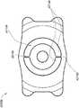
在某些实施方案中,眼内植入物包括植入体。该植入体可包括植入体中的针孔开口(pin-hole aperture)以及基本上包绕该针孔开口的掩盖物。该植入体还可包括外部孔区域,其基本上位于掩盖物外周以外。所述外部孔区可包括至少一个外部孔和至少一个连接部分。该植入体的外部区域可通过至少一个连接部分连接至掩盖物。In certain embodiments, the intraocular implant comprises an implant. The implant can include a pin-hole aperture in the implant and a mask substantially surrounding the pin-hole aperture. The implant may also include an outer aperture region located substantially outside the periphery of the mask. The outer aperture region may comprise at least one outer aperture and at least one connecting portion. The outer region of the implant can be connected to the mask by at least one connecting portion.
在一些实施方案中,眼内装置包括包含具有过渡区之表面的透镜体和掩盖物,设置所述过渡区用于减小透镜体沿透镜体之光轴的厚度,设置所述掩盖物用于阻挡由光穿过过渡区产生的实质性部分光学像差。In some embodiments, an intraocular device includes a lens body comprising a surface having a transition region configured to reduce the thickness of the lens body along the optical axis of the lens body, and a mask configured to A substantial portion of the optical aberrations produced by light passing through the transition region is blocked.
在另一些实施方案中,眼内装置包括包含第一表面和第二表面的透镜体。所述第一表面包括第一部分、第二部分和第三部分。所述透镜体的光轴穿过所述第一部分,并且所述第二部分位于所述第一部分和第三部分之间。该眼内装置还可包括位于所述第二表面与所述第一表面之第二部分之间的掩盖物。从与第二部分相邻的第一部分到垂直于光轴且与第二表面相切的平面可构成“第一距离”,从与第二部分相邻的第三部分到与垂直于光轴且与第二表面相切的平面构成“第二距离”,该第二距离大于第一距离。In other embodiments, an intraocular device includes a lens body comprising a first surface and a second surface. The first surface includes a first portion, a second portion and a third portion. The optical axis of the lens body passes through the first portion, and the second portion is located between the first portion and the third portion. The intraocular device may also include a mask positioned between the second surface and the second portion of the first surface. A "first distance" may be formed from a first portion adjacent to the second portion to a plane perpendicular to the optical axis and tangent to the second surface, and from a third portion adjacent to the second portion to a plane perpendicular to the optical axis and tangent to the second surface. A plane tangent to the second surface constitutes a "second distance", which is greater than the first distance.
在另一些实施方案中,改善患者视力的方法包括提供一种眼内装置,其包括包含具有过渡区之表面的透镜体,所述过渡区可设置用于减小透镜体沿透镜体之光轴的厚度。该眼内装置还可包括掩盖物,其被设置用于阻挡由光穿过过渡区产生的实质性部分光学像差。该方法还可包括将所述眼内装置插入眼睛的眼内空间中。In other embodiments, a method of improving vision in a patient comprises providing an intraocular device comprising a lens body comprising a surface having a transition region configured to reduce the optical axis of the lens body along the optical axis of the lens body. thickness of. The intraocular device may also include a mask configured to block a substantial portion of optical aberrations produced by light passing through the transition region. The method may also include inserting the intraocular device into the intraocular space of the eye.
在某些实施方案中,眼内植入物包括植入体,其包含具有后表面和前表面的外表面以及位于植入体之后表面和前表面之间的不透明掩盖物。所述掩盖物包含开口。该眼内植入物还可包括支持构件,其与所述掩盖物偶联并从掩盖物延伸到植入体的外表面。所述支持构件可从掩盖物延伸到植入体的后表面。与掩盖物相邻的支持构件之第一部分可具有与掩盖物平行的第一横截面,与后表面相邻的支持构件之第二部分可具有与掩盖物平行的第二横截面,所述第二横截面小于第一横截面。所述支持构件可设置为可从眼内植入物上去除。所述支持构件可包括具有以下特征的一系列孔:改变所述一系列孔的孔之大小、形状、取向和间距中至少一个从而降低所述孔产生可见衍射图案的趋势。In certain embodiments, an intraocular implant includes an implant comprising an outer surface having a posterior surface and an anterior surface, and an opaque mask positioned between the posterior and anterior surfaces of the implant. The mask includes an opening. The intraocular implant may also include a support member coupled to the mask and extending from the mask to the outer surface of the implant. The support member may extend from the mask to the posterior surface of the implant. A first portion of the support member adjacent to the mask may have a first cross-section parallel to the mask, and a second portion of the support member adjacent the back surface may have a second cross-section parallel to the mask, said first The second cross section is smaller than the first cross section. The support member may be configured to be removable from the intraocular implant. The support member may comprise a series of holes characterized by varying at least one of the size, shape, orientation and spacing of the holes of the series of holes so as to reduce the tendency of the holes to produce a visible diffraction pattern.
在某些实施方案中,制备眼内植入物的方法包括提供不透明的掩盖物,其包含开口以及与掩盖物偶联的至少一个支持构件;将掩盖物置于模具腔室内,以使至少一个支持构件与模具腔室偶联从而使掩盖物不能移动;将透镜材料浇入模具腔室中从而使掩盖物之至少一部分被透镜材料包裹。该方法还可包括在注入透镜材料后去除至少一个支持构件的至少一部分。In certain embodiments, a method of making an intraocular implant includes providing an opaque mask comprising an opening and at least one support member coupled to the mask; placing the mask in a mold cavity such that the at least one support member The member is coupled to the mold cavity such that the mask is immobile; the lens material is poured into the mold cavity such that at least a portion of the mask is surrounded by the lens material. The method may also include removing at least a portion of at least one support member after injecting the lens material.
在另一些实施方案中,制备眼内植入物的方法包括将具有开口的不透明掩盖物与模具腔室之表面偶联,并将透镜材料浇入模具腔室以形成与掩盖物偶联的光学元件。In other embodiments, a method of making an intraocular implant includes coupling an opaque mask having an opening to a surface of a mold cavity, and pouring lens material into the mold cavity to form an optical lens coupled to the mask. element.
在另一些实施方案中,制备眼内植入物的方法包括去除光学元件表面的一部分以形成环绕开口区域的环形腔,使用不透明材料至少部分地填充所述腔,去除该光学元件的至少部分开口区域和中心区域以减小光学元件开口区域的厚度。至少部分不透明材料可保留在光学元件的表面上以形成不透明掩盖物。In other embodiments, the method of making an intraocular implant comprises removing a portion of the surface of the optical element to form an annular cavity surrounding the open area, at least partially filling the cavity with an opaque material, removing at least a portion of the opening of the optical element area and central area to reduce the thickness of the optical element opening area. At least a portion of the opaque material may remain on the surface of the optical element to form an opaque mask.
在另一实施方案中,制备眼内植入物的方法包括提供具有环绕于开口区域之环形腔的光学元件,使用不透明材料至少部分地填充所述腔,去除该光学元件的至少部分开口区域和中心区域以减小光学元件开口区域的厚度。至少部分不透明材料可保留在光学元件的表面上以形成不透明掩盖物。In another embodiment, a method of making an intraocular implant includes providing an optical element having an annular cavity surrounding an opening area, at least partially filling the cavity with an opaque material, removing at least a portion of the optical element's opening area and central area to reduce the thickness of the optical element opening area. At least a portion of the opaque material may remain on the surface of the optical element to form an opaque mask.
在又一些实施方案中,制备眼内植入物的方法包括将具有开口之不透明掩盖物置于模具腔内,使掩盖物不与所述模具腔发生物理接触;将植入体材料浇入模具腔内以形成环绕掩盖物的植入体。例如,所述掩盖物可与磁场或者从该掩盖物延伸到模具腔外之框(frame)的线一起放置。In yet other embodiments, a method of making an intraocular implant includes placing an opaque mask having an opening in a mold cavity such that the mask does not physically contact the mold cavity; pouring implant material into the mold cavity inside to form an implant around the mask. For example, the mask may be placed with a magnetic field or a wire extending from the mask to a frame outside the mold cavity.
在某些实施方案中,眼内植入物包括包含主体材料的植入体和置于该植入体中具有开口的掩盖物。所述掩盖物可包括在该掩盖物后表面和前表面之间延伸的一系列孔。所述主体材料可延伸穿过该掩盖物的一系列孔,并且所述一系列孔可具有如下特征:改变所述一系列孔的孔之大小、形状、取向和间距中至少一个从而降低所述孔产生可见衍射图案的趋势。所述一系列孔可以不规则方式排布。第一系列孔可具有第一孔径、形状或间距,至少另一系列孔可具有不同于所述第一系列孔的第二孔径、形状或间距。第一系列孔可具有第一孔径,第二系列孔可具有不同于第三孔径的第二孔径,第三系列孔可具有不同于所述第一孔径和第二孔径的第三孔径。In certain embodiments, an intraocular implant includes an implant comprising a host material and a mask having an opening disposed in the implant. The mask may comprise a series of apertures extending between the rear surface and the front surface of the mask. The host material may extend through a series of holes of the mask, and the series of holes may be characterized by varying at least one of the size, shape, orientation and spacing of the holes of the series of holes to reduce the The tendency of holes to produce visible diffraction patterns. The series of holes may be arranged in an irregular manner. A first series of holes may have a first pore size, shape or spacing and at least another series of holes may have a second pore size, shape or spacing different from said first series of holes. The first series of holes may have a first pore size, the second series of holes may have a second pore size different from the third pore size, and the third series of holes may have a third pore size different from the first and second pore sizes.
在某些实施方案中,眼内植入物包括设置植入患者眼睛之小沟(sulcus)区域的植入体。该植入体可包括开口,该开口至少部分地由形成掩盖物的不透明区域和基本上位于掩盖物外周以外的外部孔区域所包绕。所述外部孔区域可包括至少一个外部孔和至少一个连接部分,并且该外部孔区域可具有至少90%的入射可见光透过率。该植入体还可包括通过至少一个连接部分与掩盖物连接的外部区域。In certain embodiments, intraocular implants include implants positioned for implantation in the sulcus region of a patient's eye. The implant may comprise an opening at least partially surrounded by an opaque region forming a mask and an outer aperture region substantially outside the periphery of the mask. The outer hole region may include at least one outer hole and at least one connection portion, and the outer hole region may have an incident visible light transmittance of at least 90%. The implant may also include an outer region connected to the mask by at least one connecting portion.
在另一些实施方案中,制备眼内植入物的方法包括提供设置植入患者眼睛小沟区域的植入体;通过去除植入体之一部分在植入体中形成开口;以及在该结构的外缘与邻近于所述开口的不透明掩盖物区域之间形成至少一个开口。In other embodiments, a method of making an intraocular implant includes providing an implant configured to be implanted in the minor groove region of a patient's eye; forming an opening in the implant by removing a portion of the implant; and At least one opening is formed between the outer edge and a region of the opaque mask adjacent to the opening.
附图说明Description of drawings
图1A示意如本文所述之在后表面上具有凹陷中心区域的眼内透镜实施方案的正视平面图。Figure 1A illustrates a front plan view of an embodiment of an intraocular lens as described herein having a depressed central region on the posterior surface.
图1B示意图1A之眼内透镜的横截面视图。Figure 1B schematically shows a cross-sectional view of the intraocular lens of 1A.
图2A示意如本文所述之在前表面上具有凹陷中心区域的眼内透镜实施方案的正视平面图。Figure 2A illustrates a front plan view of an embodiment of an intraocular lens as described herein having a recessed central region on the anterior surface.
图2B示意图2A之眼内透镜的横截面视图。Figure 2B schematically shows a cross-sectional view of the intraocular lens of 2A.
图3A示意如本文所述之在后表面和前表面上具有凹陷中心区域的眼内透镜实施方案的正视平面图。Figure 3A illustrates a front plan view of an embodiment of an intraocular lens as described herein having a recessed central region on the posterior and anterior surfaces.
图3B示意图3A之眼内透镜的横截面视图。Figure 3B schematically shows a cross-sectional view of the intraocular lens of 3A.
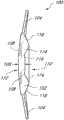
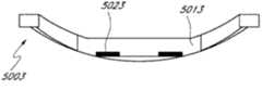
图4A示意如本文所述之具有两个过渡区和两个掩盖物的眼内透镜实施方案的正视平面图。Figure 4A illustrates a front plan view of an embodiment of an intraocular lens as described herein having two transition zones and two masks.
图4B示意图4A之眼内透镜的横截面视图。Figure 4B schematically shows a cross-sectional view of the intraocular lens of 4A.
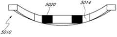
图5A示意如本文所述之具有两个过渡区和单个掩盖物的眼内透镜实施方案的正视平面图。Figure 5A illustrates a front plan view of an embodiment of an intraocular lens as described herein having two transition zones and a single mask.
图5B示意图5A之眼内透镜的横截面视图。Figure 5B schematically shows a cross-sectional view of the intraocular lens of 5A.
图6A示意如本文所述之具有凹后表面和正光学聚焦能力的眼内透镜实施方案的正视平面图。Figure 6A illustrates a front plan view of an embodiment of an intraocular lens having a concave posterior surface and positive optical focusing power as described herein.
图6B示意图6A之眼内透镜的横截面视图。Figure 6B schematically shows a cross-sectional view of the intraocular lens of 6A.
图7A示意如本文所述之具有凹后表面和负光学聚焦能力的眼内透镜实施方案的正视平面图。Figure 7A illustrates a front plan view of an embodiment of an intraocular lens having a concave posterior surface and negative optical focusing power as described herein.
图7B示意图7A之眼内透镜的横截面视图。Figure 7B schematically shows a cross-sectional view of the intraocular lens of 7A.
图8是光穿过图2B之眼内透镜的横截面示意图。Fig. 8 is a schematic cross-sectional view of light passing through the intraocular lens of Fig. 2B.
图9是来自远处物体的光穿过具有囊袋(capsular bag)内眼内透镜之一个实施方案的眼睛的示意图。Figure 9 is a schematic illustration of light from a distant object passing through an eye with one embodiment of an intraocular lens in a capsular bag.
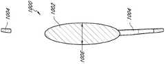
图10A示意常规眼内透镜的俯视图。Figure 10A illustrates a top view of a conventional intraocular lens.
图10B示意图10A之常规眼内透镜的横截面视图。Figure 10B schematically shows a cross-sectional view of the conventional intraocular lens of 10A.
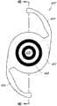
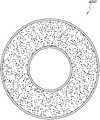
图11A是掩盖物之一个实施方案的透视图。Figure 11A is a perspective view of one embodiment of a mask.
图11B是基本上平的掩盖物之一个实施方案的透视图。Figure 1 IB is a perspective view of one embodiment of a substantially flat mask.
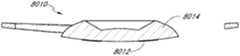
图12是厚度不均掩盖物之一个实施方案的侧视图。Figure 12 is a side view of one embodiment of an uneven thickness mask.
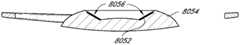
图13是厚度不均掩盖物之另一实施方案的侧视图。Figure 13 is a side view of another embodiment of the uneven thickness mask.
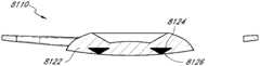
图14是具有向掩盖物提供不透明度之材料的掩盖物的一个实施方案的侧视图。Figure 14 is a side view of one embodiment of a mask with a material that provides opacity to the mask.
图15是如下掩盖物之一个实施方案的放大简图,所述掩盖物包含适于在弱光环境下选择性地控制光穿过掩盖物的微粒结构。Figure 15 is an enlarged schematic view of one embodiment of a mask comprising particulate structures adapted to selectively control light passing through the mask in low light environments.
图16是强光环境下图15之掩盖物的视图。Fig. 16 is a view of the mask of Fig. 15 under a strong light environment.
图17是包含用于将掩盖物固定在眼内之连接器的掩盖物的另一实施方案。Figure 17 is another embodiment of a mask including connectors for securing the mask in the eye.
图18A是设置用于增加聚焦深度的掩盖物的另一实施方案的俯视图。Figure 18A is a top view of another embodiment of a mask positioned to increase depth of focus.
图18B是图18A之部分视图的放大视图。Figure 18B is an enlarged view of the partial view of Figure 18A.
图19是图18A之掩盖物沿截面19-19的横截面视图。Figure 19 is a cross-sectional view of the mask of Figure 18A taken along section 19-19.
图20A是对于可在图18A之掩盖物上形成的一系列孔的一种孔排列的示意图。Figure 20A is a schematic illustration of a hole arrangement for a series of holes that may be formed in the mask of Figure 18A.
图20B是对于可在图18A之掩盖物上形成的一系列孔的另一种孔排列的示意图。Figure 20B is a schematic illustration of another hole arrangement for a series of holes that may be formed in the mask of Figure 18A.
图20C是对于可在图18A之掩盖物上形成的一系列孔的另一种孔排列的示意图。Figure 20C is a schematic illustration of another hole arrangement for a series of holes that may be formed in the mask of Figure 18A.
图21A是类似于图18A的放大视图,其显示具有非均一孔径之掩盖物的变动。FIG. 21A is an enlarged view similar to FIG. 18A showing variation of a mask with non-uniform pore size.
图21B是类似于图18A的放大视图,其显示具有非均一面取向之掩盖物的变动。FIG. 21B is an enlarged view similar to FIG. 18A showing variation of a mask with non-uniform planar orientation.
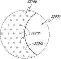
图22是具有孔区域和周围区域之掩盖物的另一实施方案的俯视图。Figure 22 is a top view of another embodiment of a mask having a hole region and a surrounding region.
图23是示意制备具有掩盖物之眼内植入物的一种方法的流程图,其由含有高度氟化之聚合物和遮光剂(opacification agent)的掩盖物制得。Figure 23 is a flow diagram illustrating one method of making an ocular implant with a mask made from a mask comprising a highly fluorinated polymer and an opacification agent.
图24A是如本文所述设置用于增加聚焦深度之掩盖物一个实施方案的俯视平面图。24A is a top plan view of one embodiment of a mask positioned as described herein to increase depth of focus.
图24B是如本文所述设置用于增加聚焦深度之掩盖物的一个实施方案的正视平面图。Figure 24B is a front plan view of one embodiment of a mask positioned as described herein for increasing depth of focus.
图24C是如本文所述设置用于增加聚焦深度之掩盖物的一个实施方案的正视平面图。Figure 24C is a front plan view of one embodiment of a mask positioned as described herein for increasing depth of focus.
图24D是如本文所述设置用于增加聚焦深度之掩盖物的一个实施方案的正视平面图。Figure 24D is a front plan view of one embodiment of a mask positioned as described herein for increasing depth of focus.
图25A是如本文所述具有与过渡区前表面偶联之掩盖物的眼内植入物一个实施方案的横截面视图。Figure 25A is a cross-sectional view of one embodiment of an intraocular implant as described herein having a mask coupled to the anterior surface of the transition zone.
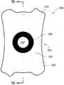
图25B是如本文所述具有与过渡区后表面偶联之掩盖物的眼内植入物一个实施方案的横截面视图。Figure 25B is a cross-sectional view of one embodiment of an intraocular implant as described herein having a mask coupled to the posterior surface of the transition zone.
图25C是如本文所述具有嵌入植入体内且位于前后表面中间之掩盖物的眼内植入物一个实施方案的横截面视图。Figure 25C is a cross-sectional view of one embodiment of an intraocular implant as described herein with a mask embedded in the implant and positioned intermediate the front and rear surfaces.
图25D是如本文所述具有嵌入植入体内且与距离后表面相比更接近前表面之掩盖物的眼内植入物一个实施方案的横截面视图。Figure 25D is a cross-sectional view of one embodiment of an intraocular implant as described herein with a mask embedded in the implant and closer to the anterior surface than to the posterior surface.
图25E是如本文所述具有嵌入植入体内且与距离前表面相比更接近后表面之掩盖物的眼内植入物一个实施方案的横截面视图。Figure 25E is a cross-sectional view of one embodiment of an intraocular implant as described herein having a mask embedded in the implanted body closer to the posterior surface than to the anterior surface.
图25F是如本文所述具有嵌入植入体内且非常接近于过渡区前表面之掩盖物的眼内植入物一个实施方案的横截面视图。Figure 25F is a cross-sectional view of one embodiment of an intraocular implant as described herein with a mask embedded in the body in close proximity to the anterior surface of the transition zone.
图25G是如本文所述具有在前后表面之间延伸之掩盖物的眼内植入物一个实施方案的横截面视图。Figure 25G is a cross-sectional view of one embodiment of an intraocular implant as described herein having a mask extending between the anterior and posterior surfaces.
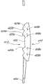
图26A是如本文所述具有从掩盖物延伸至植入体外周表面之支持构件的眼内植入物一个实施方案的正视平面图。26A is a front plan view of one embodiment of an intraocular implant as described herein having a support member extending from the mask to the peripheral surface of the implant body.
图26B是如本文所述具有从掩盖物延伸至植入体后表面之支持构件的眼内植入物一个实施方案的横截面视图。26B is a cross-sectional view of one embodiment of an intraocular implant as described herein having a support member extending from the mask to the posterior surface of the implant.
图26C是如本文所述具有与支持构件整合之掩盖物的眼内植入物一个实施方案的横截面视图。26C is a cross-sectional view of one embodiment of an intraocular implant having a mask integrated with a support member as described herein.
图27A是如本文所述具有从掩盖物延伸至植入体后表面之调整片(tab)的眼内植入物一个实施方案的横截面视图。27A is a cross-sectional view of one embodiment of an intraocular implant as described herein having a tab extending from the mask to the posterior surface of the implant.
图27B是图27A之眼内植入物当调整片部分被去除时的横截面视图。27B is a cross-sectional view of the intraocular implant of FIG. 27A with the tab portion removed.
图28A是如本文所述具有支持构件之眼内植入物的一个实施方案的正视平面图。28A is a front plan view of one embodiment of an intraocular implant having a support member as described herein.
图28B是图28A之眼内植入物的横截面视图。Figure 28B is a cross-sectional view of the intraocular implant of Figure 28A.
图29A是与图27A之眼内植入物具有不同光学聚焦能力的眼内植入物一个实施方案的正视平面图。Figure 29A is a front plan view of one embodiment of an intraocular implant having a different optical focusing power than the intraocular implant of Figure 27A.
图29B是图29A之眼内植入物的横截面视图。Figure 29B is a cross-sectional view of the intraocular implant of Figure 29A.
图30A是具有放射状延伸超过过渡区外周之掩盖物的眼内透镜一个实施方案的正视平面图。Figure 30A is a front plan view of one embodiment of an intraocular lens with a mask extending radially beyond the periphery of the transition zone.
图30B是图30A之眼内植入物的横截面视图。Figure 30B is a cross-sectional view of the intraocular implant of Figure 30A.
图31A是如本文所述具有支持构件之眼内植入物的另一实施方案的正视平面图。31A is a front plan view of another embodiment of an intraocular implant having a support member as described herein.
图31B是图31A之眼内植入物的横截面视图。31B is a cross-sectional view of the intraocular implant of FIG. 31A.
图32A是如本文所述具有放射状延伸超过过渡区外周之掩盖物的眼内植入物另一实施方案的正视平面图。32A is a front plan view of another embodiment of an intraocular implant as described herein having a mask extending radially beyond the periphery of the transition zone.
图32B是图32A之眼内植入物的横截面视图。Figure 32B is a cross-sectional view of the intraocular implant of Figure 32A.
图33A是如本文所述具有支持构件之眼内植入物的又一实施方案的正视平面图。33A is a front plan view of yet another embodiment of an intraocular implant having a support member as described herein.
图33B是图33A之眼内植入物的横截面视图。Figure 33B is a cross-sectional view of the intraocular implant of Figure 33A.
图34A是如本文所述具有放射状延伸超过过渡区外周之掩盖物的眼内植入物又一实施方案的正视平面图。34A is a front plan view of yet another embodiment of an intraocular implant as described herein having a mask extending radially beyond the periphery of the transition zone.
图34B是图34A之眼内植入物的横截面视图。Figure 34B is a cross-sectional view of the intraocular implant of Figure 34A.
图35A是如本文所述具有与袢(haptic)偶联之支持构件的眼内植入物一个实施方案的正视平面图。Figure 35A is a front plan view of one embodiment of an intraocular implant having a support member coupled to a haptic as described herein.
图35B是图35A之眼内植入物的横截面视图。Figure 35B is a cross-sectional view of the intraocular implant of Figure 35A.
图36A是如本文所述具有与袢偶联之支持构件的眼内植入物又一实施方案的正视平面图。36A is a front plan view of yet another embodiment of an intraocular implant as described herein having a support member coupled to the haptics.
图36B是图36A之眼内植入物的横截面视图。Figure 36B is a cross-sectional view of the intraocular implant of Figure 36A.
图37A是眼内植入物的横截面视图。Figure 37A is a cross-sectional view of an intraocular implant.
图37B是植入体中形成腔的图37A之眼内植入物的横截面视图。37B is a cross-sectional view of the intraocular implant of FIG. 37A with a cavity formed therein.
图37C是腔中至少部分地用不透明材料填充的图37B之眼内植入物的横截面视图。37C is a cross-sectional view of the intraocular implant of FIG. 37B with the cavity at least partially filled with an opaque material.
图37D是部分不透明材料和中心区域被去除的图37C之眼内植入物的横截面视图。Figure 37D is a cross-sectional view of the intraocular implant of Figure 37C with portions of the opaque material and central region removed.
图38A是眼内植入物的横截面视图。Figure 38A is a cross-sectional view of an intraocular implant.
图38B是植入体中形成腔的图38A之眼内植入物的横截面视图。38B is a cross-sectional view of the intraocular implant of FIG. 38A with a cavity formed therein.
图38C是腔内放置有掩盖物的图38B之眼内植入物的横截面视图。Figure 38C is a cross-sectional view of the intraocular implant of Figure 38B with a mask placed within the lumen.
图38D是腔中至少部分地用植入体材料填充的图38C之眼内植入物的横截面视图。38D is a cross-sectional view of the intraocular implant of FIG. 38C with the cavity at least partially filled with implant material.
图38E是部分植入体被去除的图38D之眼内植入物的横截面视图。Figure 38E is a cross-sectional view of the intraocular implant of Figure 38D with a portion of the implant removed.
图39A是眼内植入物的横截面视图。Figure 39A is a cross-sectional view of an intraocular implant.
图39B是植入体中形成腔的图38A之眼内植入物的横截面视图。39B is a cross-sectional view of the intraocular implant of FIG. 38A with a cavity formed therein.
图39C是腔至少部分地用不透明材料填充的图39B之眼内植入物的横截面视图。39C is a cross-sectional view of the intraocular implant of FIG. 39B with the cavity at least partially filled with an opaque material.
图39D是部分不透明材料和中心区域被去除的图39C之眼内植入物的横截面视图。Figure 39D is a cross-sectional view of the intraocular implant of Figure 39C with portions of the opaque material and central region removed.
图40是如本文所述的一个掩盖物定位系统实施方案的示意图,其用于将掩盖物定位于模具腔内。Figure 40 is a schematic illustration of one embodiment of a mask positioning system as described herein for positioning a mask within a mold cavity.
图41是如本文所述之一个掩盖物定位装置实施方案的图示,该装置包括与掩盖物和框偶联的线。Figure 41 is an illustration of an embodiment of a mask positioning device as described herein, the device including wires coupled to a mask and a frame.
图42是如本文所述的悬浮在磁场中的掩盖物之一个实施方案的侧视图。42 is a side view of one embodiment of a mask suspended in a magnetic field as described herein.
图43A是如本文所述的悬浮在磁场上的掩盖物之一个实施方案的俯视图。43A is a top view of one embodiment of a mask suspended on a magnetic field as described herein.
图43B是如本文所述的悬浮在磁场上的掩盖物之另一实施方案的俯视图。43B is a top view of another embodiment of a mask suspended on a magnetic field as described herein.
图44是如本文所述的利用静电悬浮定位掩盖物之实施方案的示意图。44 is a schematic diagram of an embodiment of positioning a mask using electrostatic levitation as described herein.
图45是如本文所述的能够形成掩盖物之双稳态显示(bistabledisplay)的实施方案的俯视图。45 is a top view of an embodiment of a bistable display capable of forming a mask as described herein.
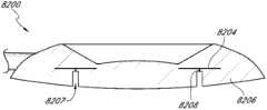
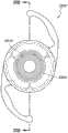
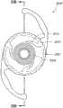
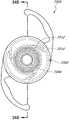
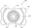
图46是如本文所述之设置用于增加聚焦深度的、具有掩盖物的眼内植入物的一个实施方案的俯视透视图。46 is a top perspective view of one embodiment of an intraocular implant with a mask configured to increase depth of focus as described herein.
图47是图46之眼内植入物的俯视平面图。47 is a top plan view of the intraocular implant of FIG. 46. FIG.
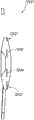
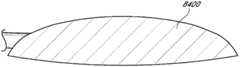
图48A是如本文所述具有贯穿图46之眼内植入物的掩盖物的眼内植入物一个实施方案的侧视垂直投影图(side elevational view)。Figure 48A is a side elevational view of one embodiment of an intraocular implant as described herein having a mask throughout the intraocular implant of Figure 46.
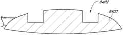
图48B是如本文所述在眼内植入物后表面上具有掩盖物的眼内植入物一个实施方案的侧视垂直投影图。Figure 48B is a side orthographic projection of one embodiment of an intraocular implant having a mask on the posterior surface of the intraocular implant as described herein.
图48C是如本文所述的在眼内植入物前表面上具有掩盖物的眼内植入物一个实施方案的侧视垂直投影图。Figure 48C is a side orthographic projection of one embodiment of an intraocular implant having a mask on the anterior surface of the intraocular implant as described herein.
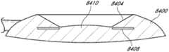
图48D是如本文所述的将掩盖物置于眼内植入物后表面和前表面中间的眼内植入物一个实施方案的侧视垂直投影图。Figure 48D is a side orthographic projection of one embodiment of an intraocular implant with a mask positioned intermediate the posterior and anterior surfaces of the intraocular implant as described herein.
图48E是如本文所述的在眼内植入物的后表面与前后表面中点中间具有掩盖物的眼内植入物一个实施方案的侧视垂直投影图。Figure 48E is a side orthographic projection of one embodiment of an intraocular implant having a mask intermediate the posterior surface and the midpoint of the anterior and posterior surfaces of the intraocular implant as described herein.
图48F是如本文所述的在眼内植入物的前表面和前后表面中点中间具有掩盖物的眼内植入物一个实施方案的侧视垂直投影图。Figure 48F is a side orthographic projection of one embodiment of an intraocular implant as described herein with a mask intermediate the anterior surface and the midpoint of the anterior and posterior surfaces of the intraocular implant.
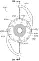
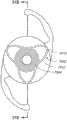
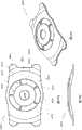
图49A是如本文所述的具有五个外部孔之眼内植入物的一个实施方案的俯视透视图。Figure 49A is a top perspective view of one embodiment of an intraocular implant having five external holes as described herein.
图49B是图56A之眼内植入物的俯视平面图。Figure 49B is a top plan view of the intraocular implant of Figure 56A.
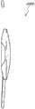
图49C是图56A之眼内植入物的侧视垂直投影图。Figure 49C is a side vertical projection of the intraocular implant of Figure 56A.
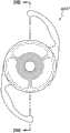
图50A是如本文所述的具有与图56A之眼内植入物不同的袢的眼内植入物一个实施方案的俯视透视图。Figure 50A is a top perspective view of one embodiment of an intraocular implant as described herein having different haptics than the intraocular implant of Figure 56A.
图50B是图57A之眼内植入物的俯视平面图。Figure 50B is a top plan view of the intraocular implant of Figure 57A.
图50C是图57A之眼内植入物的侧视垂直投影图。Figure 50C is a side vertical projection of the intraocular implant of Figure 57A.
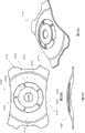
图51A是如本文所述的具有单个外部孔之眼内植入物的一个实施方案的俯视平面图。51A is a top plan view of one embodiment of an intraocular implant having a single external hole, as described herein.
图51B是如本文所述的具有两个外部孔之眼内植入物的一个实施方案的俯视平面图。Figure 5 IB is a top plan view of one embodiment of an intraocular implant as described herein having two external holes.
图51C是如本文所述的具有三个外部孔之眼内植入物的一个实施方案的俯视平面图。Figure 51C is a top plan view of one embodiment of an intraocular implant as described herein having three external holes.
图51D是如本文所述的具有四个外部孔之眼内植入物的一个实施方案的俯视平面图。Figure 5 ID is a top plan view of one embodiment of an intraocular implant having four external holes as described herein.
图51E是如本文所述的具有六个外部孔之眼内植入物的一个实施方案的俯视平面图。Figure 5 IE is a top plan view of one embodiment of an intraocular implant as described herein having six external holes.
图52是如本文所述的具有向外延伸至植入体外周附近之外部孔区域的眼内植入物一个实施方案的俯视平面图。Figure 52 is a top plan view of one embodiment of an intraocular implant as described herein having an external aperture region extending outward near the periphery of the implant.
图53A是如本文所述的具有如下外部孔区域之眼内植入物一个实施方案的俯视平面图,所述外部孔区域从开口向外延伸在一个方向上比另一方向上延伸得更远。53A is a top plan view of one embodiment of an intraocular implant as described herein having an external aperture region extending outwardly from the opening farther in one direction than the other.
图53B是如本文所述的具有非均一外部孔的眼内植入物一个实施方案的俯视平面图。Figure 53B is a top plan view of one embodiment of an intraocular implant having a non-uniform external aperture as described herein.
图54是如本文所述的具有部分地包绕开口之外部孔区域的眼内植入物一个实施方案的俯视平面图。Figure 54 is a top plan view of one embodiment of an intraocular implant as described herein having an outer hole region partially surrounding the opening.
图55是如本文所述的具有位于中心之开口和偏离中心之外部孔区域的眼内植入物一个实施方案的俯视平面图。55 is a top plan view of one embodiment of an intraocular implant as described herein having a centrally located opening and an off-center outer hole region.
图56是如本文所述的位于中心之外部孔区域和偏离中心之开口的眼内植入物一个实施方案的俯视平面图。56 is a top plan view of one embodiment of an intraocular implant with a centrally located outer aperture region and an off-center opening as described herein.
图57是如本文所述的掩盖物具有透光孔的眼内植入物一个实施方案的俯视平面图。Figure 57 is a top plan view of one embodiment of an intraocular implant having a mask with light-transmitting apertures as described herein.
图58是如本文所述的眼内植入物一个实施方案的俯视平面图,其透光孔的孔径从开口向外呈放射状逐步增加。Fig. 58 is a top plan view of one embodiment of an intraocular implant as described herein, wherein the light-transmissive apertures increase in diameter radially outward from the opening.
图59是视觉敏锐度作为散焦之函数的折线图,其对两种典型的多焦点IOL以及本文所述具有开口之眼科装置的一个实施方案进行了比较。Figure 59 is a line graph of visual acuity as a function of defocus comparing two typical multifocal IOLs and an embodiment of an ophthalmic device with an aperture described herein.
发明详述Detailed description of the invention
本申请涉及眼内植入物和植入眼内植入物的方法。当天然晶状体由于白内障而变得混浊时,常常使用眼内透镜替代天然晶状体。还可将眼内透镜植入眼睛中以矫正其它屈光缺陷,而无需去除天然晶状体。一些优选实施方案的眼内植入物包括适于提供小开口从而允许光从此通过并到达视网膜来增加聚焦深度的掩盖物,本文中有时也称其为“针孔成像”或“针孔视力矫正”。可将所述眼内植入物植入眼睛的前房或后房中。在后房的情形中,可将植入物固定于睫状沟(ciliary sulcus)中、囊袋中或者固定眼内植入物的任何位置。在下述一些实施方案中,与常规眼内透镜相比,所述眼内透镜中心区域的厚度减少。中心区域厚度的减少有助于改善眼内透镜的植入。在下述另一些实施方案中,眼内植入物可具有外部孔区域(例如穿孔区域)以改善患者的弱光视力。This application relates to intraocular implants and methods of implanting intraocular implants. When the natural lens becomes clouded due to cataracts, an intraocular lens is often used to replace the natural lens. Intraocular lenses can also be implanted in the eye to correct other refractive defects without removing the natural lens. The intraocular implants of some preferred embodiments include a mask adapted to provide a small opening to allow light to pass therethrough and to the retina to increase the depth of focus, sometimes referred to herein as "pinhole imaging" or "pinhole vision correction." ". The intraocular implant may be implanted in the anterior or posterior chamber of the eye. In the case of the posterior chamber, the implant can be secured in the ciliary sulcus, in the capsular bag, or wherever an intraocular implant is secured. In some embodiments described below, the intraocular lens has a reduced thickness in the central region compared to conventional intraocular lenses. The reduction in the thickness of the central region helps to improve the implantation of the intraocular lens. In other embodiments described below, the intraocular implant may have an external aperture region (eg, a perforated region) to improve low light vision in the patient.
I.厚度减少的眼内植入物I. Intraocular Implants with Reduced Thickness
已开发了几种定焦IOL的替代品,包括多焦点IOL和可调节IOL,其试图提供同时看清远近物体的能力。多焦点IOL针对远近物体提供了良好的视觉敏锐度,然而这些透镜对于中等距离的物体通常不能发挥很好的作用,还伴有与未聚焦光线有关的眩目、眩晕和夜视困难。已开发了几种可调节IOL,但是到目前为止仍没有哪一种能够完全呈现天然晶状体的功能。Vorosmarthy描述了具有开口的IOL(美国专利No.4,976,732)。然而,这些装置不旨在改变从远到近的焦点,而仅仅试图通过散焦使视物模糊改善至远视性正视眼(presbyopic emmetrope)可看清的水平。值得注意的是,Vorosmarthy并未提及减少具有掩盖物之IOL的厚度以用于小切口手术(small-incision surgery)。Several alternatives to fixed-focus IOLs have been developed, including multifocal IOLs and adjustable IOLs, which attempt to provide the ability to see both near and far objects. Multifocal IOLs provide good visual acuity for near and far objects, however these lenses typically do not work well for objects at intermediate distances, with associated glare, vertigo, and night vision difficulties associated with unfocused light. Several accommodating IOLs have been developed, but so far none can fully perform the functions of the natural lens. Vorosmarthy describes an IOL with an opening (US Patent No. 4,976,732). However, these devices do not aim to change the focus from far to near, but merely attempt to improve the blurred vision by defocusing to a level that is visible to a presbyopic emmetrope. It is worth noting that Vorosmarthy does not mention reducing the thickness of the IOL with a mask for small-incision surgery.
本申请的一些实施方案提供了具有掩盖物的IOL,其具有与本领域已知的相比更薄的光学元件。所述更薄的光学元件的优势在于可通过较小的切口将IOL插入眼睛中。由于角膜切口易引发角膜变形和视力损伤,所以减小切口尺寸将改善视物质量。所述光学元件利用类似于菲涅耳透镜(Fresnel lens)的方式变薄,其中交替变化的同心区域提供了聚焦能力和高度梯度(height step)。尽管减小厚度(例如利用菲涅耳透镜)是关键性的,但是高度梯度在光学上不适于临床应用。它们不将图像的光聚焦在视网膜中央凹(fovea),而是散射光线,从而导致患者的视觉出现异常闪光感(dysphotopsias)(条纹、伪影和眩晕等)。通过结合菲涅尔型高度梯度与阻挡光穿过梯度且允许光仅穿过聚焦表面的掩盖物,可消除与普通菲涅耳透镜有关的异常闪光感,从而获得厚度降低带来的益处同时不引起不期望的光学效应。Some embodiments of the present application provide IOLs with masks that have thinner optics than known in the art. The advantage of the thinner optics is that the IOL can be inserted into the eye through a smaller incision. Since corneal incisions are prone to corneal deformation and visual impairment, reducing the incision size will improve visual quality. The optics are thinned in a manner similar to a Fresnel lens, where alternating concentric regions provide focusing power and height steps. While reducing the thickness (eg using Fresnel lenses) is critical, the height gradient is not optically suitable for clinical applications. Instead of focusing the image's light on the fovea, they scatter the light, causing dysphotopsias (streaks, artifacts, and vertigo, etc.) in the patient's vision. By combining a Fresnel-type height gradient with a mask that blocks light from passing through the gradient and allows light to pass only through the focusing surface, the anomalous shimmer associated with ordinary Fresnel lenses is eliminated, allowing the benefits of reduced thickness without compromising the May cause undesired optical effects.
一般来说,通过将眼内植入物卷起并将卷起的眼内植入物插入管中来将眼内植入物植入眼中。将所述管插入眼的切口中,眼内植入物从管中弹出并在眼睛内展开。在去除天然晶状体后,眼内植入物可植入晶状体囊中,或者植入前房、后房中,并且可以与睫状沟偶联或连接(本文有时还称之为“固定于小沟”)。根据眼内植入物在眼中的位置,眼内植入物的尺寸(包括但不限于掩盖物的开口)是可以调整的。通过减小眼内透镜中心区域的厚度,所述眼内透镜可被更紧地卷起并插入更小的管中。如果使用更小的管,则可在眼中切出更小的切口。其结果是介入程度更低,并且患者的恢复时间缩短。而且,与常规的后房有晶状体的(phakic)眼内透镜相比,固定于睫状沟中的透镜厚度减小使得眼内透镜后表面与天然晶状体表面之间的空间加大,从而降低这些表面之间的潜在接触。Generally, an intraocular implant is implanted in the eye by rolling up the intraocular implant and inserting the rolled up intraocular implant into a tube. The tube is inserted into an incision in the eye, and the intraocular implant is ejected from the tube and deployed within the eye. After removal of the natural lens, intraocular implants may be implanted in the lens capsule, or in the anterior or posterior chamber, and may be coupled or attached to the ciliary sulcus (also sometimes referred to herein as "fixed to the minor sulcus"). "). Depending on the position of the intraocular implant in the eye, the size of the intraocular implant (including but not limited to the opening of the mask) is adjustable. By reducing the thickness of the central region of the intraocular lens, the intraocular lens can be rolled more tightly and inserted into a smaller tube. If a smaller tube is used, a smaller incision can be made in the eye. The result is less intervention and shorter recovery times for patients. Furthermore, the reduced thickness of the lens anchored in the ciliary sulcus increases the space between the posterior surface of the intraocular lens and the surface of the natural lens compared to conventional phakic intraocular lenses, thereby reducing these Potential contact between surfaces.
在一些实施方案中,眼内透镜100包括透镜体102,其具有折射光线的光学聚焦能力并矫正眼睛的屈光不正。图1~10示意了一些实施方案。所述眼内透镜100可包括一个或多个袢104,以防止眼内透镜100在眼中移动或转动。本文所用术语“袢”旨在表示较广的含义,其包括可挂靠在眼睛的内表面并安装到透镜结构上以确保透镜牢固地定位于眼睛光学路径上的支撑物(strut)和其它机械结构。根据眼内透镜100植入眼中的具体位置,所述袢104可具有不同的形状和尺寸。图1-10中所示的袢可与任何类型的袢互换。例如,可以将图1-10所示的袢与图1-10所示的眼内透镜组合。袢可以是C形、J形、平面设计或任何其它设计。本文所述的眼内植入物可具有两个、三个、四个或更多个袢。该袢可以为开放的或闭合的构造,并且可以是平面的、带角的或台阶拱形的(step-vaulted)。美国专利4,634,442、5,192,319、6,106,553、6,228,115、Re.34,251、7,455,691和美国专利申请2003/0199978公开了袢的实例,其通过引用整体并入本文中。In some embodiments, the
在某些实施方案中,如图1A-B所示,透镜体102包括后表面110和前表面112。透镜体102包括后表面110上的第一部分116(例如,内部部分或中心区域)、第二部分114(例如,过渡区)和第三部分118(例如,外部部分或区域)。第二部分114可在第一部分116与第三部分118之间和/或与二者相邻。第二部分114可基本上包绕第一部分116,第三部分118可以基本上包绕第二部分114。在某些实施方案中,所述第一部分116基本上是圆形的,第二部分114和第三部分118基本上是环形的。第一部分116和第三部分118可折射光线或者具有改善患者视力的光学聚焦能力。第二部分114具有一个或多个面、沟、突起、槽、凹陷、等高部分(contour)、表面弯曲等以使第一部分116较之后表面110没有第二部分114的情况更靠近前表面112。第二部分114还可以描述为第一部分116与第三部分118之间的“过渡区”。例如,第二部分114过渡区可以从第三部分118到第一部分116朝前表面112倾斜。在某些实施方案中,第二部分114过渡区包括基本上垂直于前表面112的表面。该过渡区域类似于整合进菲涅耳透镜中的过渡区。它们使透镜体可被制造得比常规透镜设计所需的更薄。然而,如同菲涅尔透镜一样,该过渡区引入了光学像差,而这种光学像差是眼内透镜临床不能接受的。In certain embodiments, as shown in FIGS. 1A-B ,
眼内透镜100可以包括掩盖物108,设置该掩盖物从而阻挡从后表面110的第二部分114过渡区穿过的实质性部分光线。本文中使用的“阻挡”包括阻止至少部分光线穿过掩盖物,以及阻止基本上所有光线穿过掩盖物。如果没有掩盖物108阻挡穿过第二部分114的光线,由于光线在第二部分114中的折射(例如,光学聚焦能力等)通常不同于所述第一部分116和第三部分118中的折射,便会产生像差。The
在某些实施方案中,第一部分116是凸面的,第二部分114是凹面的,第三部分118是凸面的。在某些实施方案中,第一部分116和第三部分118具有正的或会聚的光学聚焦能力,而第二部分114具有负的或发散的光学聚焦能力。第二部分114可以从第一部分116向第三部分118径向延伸的方向上具有曲率或无曲率。例如,第二部分114可以从第一部分116向第三部分118径向延伸的方向上具有正或负的曲率(例如,凸面或凹面)。此外,第二部分114可形成闭合的环并具有类似于截锥形外表面的表面。In certain embodiments, the
在某些实施方案中,第一部分116在透镜体102的中心区域132中。中心区域132可凹陷进透镜体102内。在某些实施方案中,第三部分118在透镜体102的外部区域130中。在某些实施方案中,第一部分116的外周被第二部分114的内周包绕和/或围绕。在某些实施方案中,第二部分114的外周被第三部分118的内周包绕和/或围绕。在某些实施方案中,透镜体102在第一部分116区域中的最大厚度小于透镜体在第二部分114区域中的最大厚度。In certain embodiments, the
在某些实施方案中,如图2A-B所示,透镜体202包括前表面212上的第一部分222、第二部分220和第三部分224。在前表面212上的第一部分222、第二部分220和第三部分的224可具有与前述在前表面112上的第一部分116、第二部分114和第三部分118相似的特征。该眼内透镜200可包括掩盖物208,设置该掩盖物从而阻挡穿过前表面212之第二部分220的实质性部分光线。In certain embodiments, as shown in FIGS. 2A-B , lens body 202 includes first portion 222 , second portion 220 , and third portion 224 on front surface 212 . The first portion 222 , the second portion 220 and the third portion 224 on the front surface 212 may have similar features as the
在某些实施方案中,如图3A-B所示,前表面312和后表面310具有第一部分316、322,第二部分314、320和第三部分318、324。设置掩盖物308可阻挡穿过前表面312之第二部分320和穿过后表面310之第二部分314的实质性部分光线。In certain embodiments, as shown in FIGS. 3A-B , the
在某些实施方案中,掩盖物与凹面的第二部分偶联。例如,可将掩盖物置于与第二部分相邻的位置。在某些实施方案中,掩盖物与后表面、前表面或者前后表面连接。在某些实施方案中,掩盖物在透镜体内或者在前后表面之间。掩盖物的径向宽度或面积可以与第二部分的径向宽度或面积大致相同。在某些实施方案中,掩盖物可至少部分地延伸到透镜体的第一部分和/或第三部分的区域。通过将掩盖物延伸到第一部分和/或第三部分,掩盖物可阻挡以大的偏角进入透镜体之光学中心轴并继而可穿过第二部分的光。In certain embodiments, a mask is coupled to the concave second portion. For example, a mask may be positioned adjacent to the second portion. In certain embodiments, the mask is attached to the posterior surface, the anterior surface, or the anterior and posterior surfaces. In certain embodiments, the mask is within the body of the lens or between the front and rear surfaces. The radial width or area of the mask may be approximately the same as the radial width or area of the second portion. In certain embodiments, the mask can extend at least partially into the area of the first portion and/or the third portion of the lens body. By extending the mask to the first part and/or the third part, the mask can block light entering the optical central axis of the lens body at large off angles and then passing through the second part.
如图4A-B所示,眼内透镜400还可包括前表面412和/或后表面410上的第四部分420b和第五部分424b。第四部分420b与第三部分424a相邻,并可基本上包绕第三部分424a。第五部分424b与第四部分420b相邻,并可基本上包绕第四部分420b。第四部分420b可具有与上文所述第二部分420a相似的特征,第五部分424b可具有与上文所述第三部分424a相似的特征。眼内透镜400可以包括第一掩盖物408a和第二掩盖物408b,设置该第一掩盖物用于阻挡穿过前表面412之第二部分420a的实质性部分光线,设置该第二掩盖物用于阻挡穿过前表面412之第四部分420b的实质性部分光线。应当理解,眼内透镜中还可包括额外成对的具有掩盖物的部分,例如第四部分420b、第五部分424b和第二掩盖物408b。As shown in FIGS. 4A-B , the
图5A-B示意类似于图4A-B所示眼内透镜400的眼内透镜500。与具有第一掩盖物408a和第二掩盖物408b的眼内透镜400不同的是,所述眼内透镜500具有单个掩盖物508,该掩盖物具有允许至少部分光线透过掩盖物508的一系列透光孔。设置所述透光孔可使得穿过第二部分520a和第四部分520b的光线基本上不会穿过掩盖物508,但允许至少部分穿过第三部分524a的光穿过掩盖物508。例如,掩盖物的中间环形区域可具有一系列孔,从而使至少部分光线穿过掩盖物,并且内环区域和外环区域可基本上无孔。下文还将继续讨论光透过结构或孔,并且其可应用于本文所述的实施方案中。Figures 5A-B illustrate an
本文描述的眼内透镜类型是为适应具体患者的视力矫正需要而设计的。例如,与瞳孔较大的患者相比,弱光可对瞳孔较小的患者造成更多的视物问题。对于瞳孔较小的患者,具有更大的透光能力和/或更小外径的掩盖物将会增加到达视网膜的光量,从而可以改善在弱光条件下的视力。反之,对于瞳孔较大的患者,具有较低的透光能力和/或较大外径的掩盖物可以改善视近物的低对比度并阻挡更多未聚焦的光。本文所述的掩盖型IOL为外科医生向具体患者指定合适的掩盖型IOL特征组合提供了灵活性。The types of intraocular lenses described herein are designed to suit the vision correction needs of a particular patient. For example, low light can cause more vision problems in patients with smaller pupils than in patients with larger pupils. For patients with small pupils, a mask with greater light transmission capacity and/or a smaller outer diameter will increase the amount of light reaching the retina, which may improve vision in low-light conditions. Conversely, for patients with larger pupils, a mask with lower light transmission capability and/or larger outer diameter can improve low contrast in near vision and block more unfocused light. The masking IOLs described herein provide flexibility for the surgeon to prescribe the appropriate combination of masking IOL features for a particular patient.
图6-7示意眼内透镜600和700的另外实施方案。眼内透镜后表面和前表面可具有不同的曲率。例如,所述后表面和/或前表面可以是凹面或凸面的。图6A-B示意一种眼内透镜600,其具有凹面的后表面610和前表面612从而形成具有正光学聚焦能力的透镜。图7A-B示意眼内透镜700,其具有凹面的后表面710和前表面712从而形成具有负光学聚焦能力的透镜。眼内透镜600和700均具有第二部分620和720以减少眼内透镜600、700的整体厚度。眼内透镜600和700均还可包括掩盖物608和708以阻挡穿过第二部分620和720的光线。对于具有负光学聚焦能力的眼内透镜(例如图7所示的眼内透镜700),透镜体702的中心区域732的厚度可以不借助第二部分720而降低。然而,透镜体702的外部区域730的厚度可以借助第二部分720(例如,过渡区)而降低。有利地,如果眼内透镜具有正或负的光学聚焦能力,可通过使透镜体具有第二部分而降低至少部分透镜体的厚度。6-7 illustrate additional embodiments of
表I和II示意透镜体厚度降低的眼内透镜实例。标有“减少”的栏对应于具有第二部分(例如过渡区)的眼内透镜,而标有“初始”的栏对应于没有第二部分的眼内透镜。所述光学元件的直径是具有光学聚焦能力之透镜体的最外部部分的直径。表I和表II中所示的相比于中心区域厚度的减少百分比可以是厚度降低之IOL可能卷起的直径的大致减少比例。因此,表I和表H中所示的中心区域厚度的减少百分比也可以是在向患者植入IOL时可使用切口尺寸的大致减少比例。IOL被卷起并插入管中,继而将所述管插入切口中。然后,IOL可在眼睛的眼内空间中展开。通常将IOL尽可能地卷紧以使得在管横截面内的开放空间(例如空隙)最小化,所述管的位置使得植入体具有最大的横截面面积,该横截面通常与植入体的光轴平行。因此,所述管的横截面面积大于或等于植入体的最大横截面面积,该横截面通常与植入体的光轴平行。例如,植入体横截面面积降低36%可以使管的横截面面积降低36%,或可以使管的直径降低约20%。最小切口长度通常为管周长的一半。因此,植入体横截面面积减少36%可以降低约20%的切口长度。例如,1.8mm切口可以降低到约1.44mm。较小的切口具有益处,因为其避免了手术后的散光。Tables I and II illustrate examples of intraocular lenses with reduced lens body thickness. The column labeled "Reduced" corresponds to an intraocular lens with a second portion (eg, transition zone), while the column labeled "Initial" corresponds to an intraocular lens without a second portion. The diameter of the optical element is the diameter of the outermost portion of the lens body having optical focusing power. The percentage reductions shown in Tables I and II compared to the central region thickness may be approximate reductions in the diameter that a reduced thickness IOL may roll up. Accordingly, the percentage reductions in central region thickness shown in Tables I and H may also be approximate reductions in incision size that may be used when implanting an IOL into a patient. The IOL is rolled up and inserted into the tube, which is then inserted into the incision. The IOL can then be deployed in the intraocular space of the eye. The IOL is typically rolled as tightly as possible to minimize open space (e.g., voids) within the cross-section of the tube positioned so that the implant has the largest cross-sectional area, which is usually the same as that of the implant. The optical axes are parallel. Thus, the cross-sectional area of the tube is greater than or equal to the largest cross-sectional area of the implant, which cross-section is generally parallel to the optical axis of the implant. For example, a 36% reduction in the cross-sectional area of the implant can reduce the cross-sectional area of the tube by 36%, or can reduce the diameter of the tube by about 20%. The minimum incision length is usually half the circumference of the tube. Thus, a 36% reduction in implant cross-sectional area can reduce incision length by approximately 20%. For example, a 1.8mm incision can be reduced to about 1.44mm. A smaller incision is beneficial because it avoids post-operative astigmatism.
表I.具有正光学聚焦能力的厚度降低之IOL的实例。Table I. Examples of reduced thickness IOLs with positive optical focusing power.

表II.具有负光学聚焦能力的厚度降低之IOL的实例。Table II. Examples of reduced thickness IOLs with negative optical focusing power.

图8示意图2A-B所示的眼内透镜200的运作。在使用中,光线进入眼内透镜200的前表面212,穿过其透镜体202并从其后表面210穿出。掩盖物208的定位使其阻挡穿过前表面212之第二部分220的实质性部分光线850,如图8所示。如果没有掩盖物208阻挡穿过第二部分220的光线850,将会产生像差。例如,如果所述第二部分220的曲率设置用于提供负的或发散的光学聚焦能力,则穿过该区域的光线860将会发散且不聚焦,如图8所示。穿过第一部分222和/或第三部分224的光线850将具有正的或汇聚的光学聚焦能力。如果第一部分222和第三部分224具有类似的曲率或光学聚焦能力,则穿过后表面210后,进入前表面212并穿过第一部分222和/或第三部分224的光线450将会汇聚在共同点870,如图8所示。图9A示意一种眼内透镜200,其被植入眼睛952的囊袋954内。穿过眼内透镜200的平行光线950汇聚在视网膜956上。Figure 8 schematically illustrates the operation of the
透镜体202可包括一种或多种材料。在某些实施方案中,透镜体202包括两种或更多种材料。例如,第一部分222和第三部分224可以包括不同的材料。如果为第一部分222和第三部分224选择的材料具有不同的折射率,则第一部分222和第三部分224的曲率可以是不同的从而使这两部分获得类似的光学聚焦能力(例如,屈光能力)。Lens body 202 may comprise one or more materials. In certain embodiments, lens body 202 includes two or more materials. For example, first portion 222 and third portion 224 may comprise different materials. If the materials selected for the first portion 222 and the third portion 224 have different indices of refraction, the curvatures of the first portion 222 and the third portion 224 may be different so that the two portions achieve similar optical focusing capabilities (e.g., dioptric ability).
一般来说,选择眼内透镜的光学聚焦能力用于聚焦远处物体。天然晶状体可根据视物远近进行变形以改变焦距。常规的人工眼内透镜通常无法改变焦距。例如,老花眼或人工眼内透镜具有视远物的光学聚焦能力,光线进入眼睛并穿过角膜和天然晶状体或人工眼内透镜汇聚到视网膜后面或前面的点,而不汇聚在视网膜上。所述光线投射在视网膜上较大的区域,而不是汇聚于视网膜上的一点。所述患者会感到视物模糊,特别是对于近处的物体(例如阅读时)。针对这样的情况,可设置具有开口的眼内透镜200之掩盖物208,从而使仅有一部分光线(例如中心部分的光线)到达视网膜。该具有开口的掩盖物208可以提高人眼的聚焦深度。例如,所述开口可以是针孔开口。该掩盖物208阻挡部分外部光线,使得光线更集中。该掩盖物208可包括包绕开口的环形区域。该开口可以基本上位于掩盖物的中心。例如,开口可位于掩盖物中心轴(也称为掩盖物的光轴)附近。所述掩盖物的开口可以是圆形或任何其它形状的。In general, the optical focusing power of the intraocular lens is selected for focusing on distant objects. The natural lens deforms to change the focal length according to the distance seen. Conventional artificial intraocular lenses are usually unable to change the focal length. For example, presbyopia or artificial intraocular lenses have the optical focusing ability for distance vision, light rays entering the eye travel through the cornea and natural crystalline lens or artificial intraocular lenses to converge to a point behind or in front of the retina, but not on the retina. The light rays hit a larger area on the retina instead of converging on a single point on the retina. The patient experiences blurred vision, especially with nearby objects (eg, when reading). For such cases, the
掩盖物208可位于眼内透镜200中或其上的不同位置。所述掩盖物208可以在透镜体202之中。所述掩盖物208可以位于透镜体202的前表面或后表面。在某些实施方案中,掩盖物208被嵌入透镜体202中。例如,掩盖物208可位于透镜体202前后表面大致中线的位置。在某些实施方案中,掩盖物208位于透镜体202的中线和后表面之间。某些实施方案包括这样的掩盖物208,其位于透镜体202的中线和后表面的中间、三分之一或三分之二的位置。在另一些实施方案中,掩盖物208位于透镜体202的中线与前表面之间。某些实施方案包括这样的掩盖物208,其位于透镜体202的中线和前表面的中间、三分之一或三分之二的位置。如果过渡区在植入体的前表面上且掩盖物被置于前表面上过渡区的表面上或附近,则掩盖物可以不延伸出过渡区,这是因为即使到达或穿过过渡区表面的与光轴呈大角度的光线也会被掩盖物阻挡。The
在某些实施方案中,眼内透镜200的掩盖物208具有开口,其中掩盖物阻挡了部分光线以提高近物的视物能力,如同上文讨论的掩盖物一样。有利地,掩盖物208可提供开口并可以阻挡不能汇聚于视网膜956上的部分光线,还阻挡了穿过第二部分220的产生像差的光线,如上文所述。在某些实施方案中,所述掩盖物208的开口直径约为1~2mm。在某些实施方案中,所述掩盖物208的外周直径约为3~5mm。In certain embodiments, the
在某些实施方案中,眼内透镜200的第三部分224可以提高弱光视力。随着眼睛瞳孔扩大,光线最终进入并穿过眼内透镜200的第三部分224。如图9所示,如果眼睛952的瞳孔958大到足以使光线950穿过眼内透镜200的第三部分224,则额外的光线950会投射在视网膜上。如上文讨论,眼内透镜200可以具有矫正视远物的光学聚焦能力,以使从远处物体发出的光线聚焦于视网膜上的一点。如果眼内透镜200具有视远物的光学聚焦能力,则在弱光条件下视近物可产生不聚焦的图像。In some embodiments, the third portion 224 of the
掩盖物208可具有不同程度的不透明度。例如,所述掩盖物208可阻挡基本上全部的可见光或者可阻挡部分可见光。掩盖物208的不透明度也可以在掩盖物208不同区域中有所不同。在某些实施方案中,掩盖物208之外边缘和/或内边缘的不透明度小于其中心区域的不透明度。不同区域的不透明度可以不连续地过渡或梯度过渡。不透明度过渡的其它实例可见于美国专利5,662,706、5,905,561和5,965,330中,其通过引用整体并入本文中。
图10A-B示意常规的眼内透镜1000。通过在透镜体302的后表面310(由第二部分314形成)和/或前表面312(由第二部分320形成)上设置凹陷部分,与无此凹陷部分的常规透镜体1002相比,眼内透镜300的最大厚度得以降低,如图10B所示。透镜体1002的横截面厚度通常取决于眼内透镜1000的光学聚焦能力和透镜体1002的材料。特别地,透镜体1002的中心区域通常是眼内透镜1000的最厚部分,其具有中心区域横截面厚度1006。在本文公开的某些实施方案中,眼内透镜200的透镜体202的中心区域厚度206小于其它普通透镜体的中心区域厚度1006。在图3B所示的实施方案中,与常规眼内透镜1000相比,厚度306被进一步降低了。10A-B illustrate a conventional
通常,如上文讨论地,通过将眼内透镜卷起并将卷起的眼内透镜插入管中从而使眼内透镜植入眼中。透镜体较薄的一个优点在于,可以更紧地卷起眼内透镜,从而可以使用小管和小切口。透镜体较薄的另一优点在于,该眼内透镜可降低与植入眼中不同位置有关的风险。例如,眼内透镜200可植入到前房内。眼内透镜200还可以置于后房内从而使后表面210的第一部分216浮在天然晶状体上。由于降低了眼内透镜200的厚度,从而减小了眼内透镜200的后表面210与天然晶状体相互接触的可能性。例如,眼内透镜200可以与睫状沟偶联或连接(有时称为“沟固定”)。如图9所示,眼内透镜200还可植入囊袋中。根据眼内透镜植入眼中的位置,可以调整眼内透镜200的尺寸(包括但不限于掩盖物208的孔径)。Typically, an intraocular lens is implanted in the eye by rolling up the lens and inserting the rolled up lens into a tube, as discussed above. One advantage of a thinner lens body is that the intraocular lens can be rolled more tightly, allowing the use of small tubes and small incisions. Another advantage of a thinner lens body is that the intraocular lens reduces the risks associated with implantation in different locations in the eye. For example,
眼内透镜200和/或透镜体202可由一种或多种材料制成。在某些实施方案中,所述眼内透镜200和/或透镜体202可包括聚合物(如PMMA、PVDF、聚丙烯、聚碳酸酯、PEEK、聚乙二醇、丙烯酸类共聚物、聚苯乙烯、PVC、聚砜)、水凝胶和聚硅酮)。
II.提供聚焦深度矫正的掩盖物II. Masks that Provide Depth of Focus Correction
本文讨论了可置入植入体2014上或内部的掩盖物的多种变化形式,其也描述于美国专利No.7,628,810、美国专利申请No.2006/0113054和美国专利申请No.2006/0265058中,其通过引用整体并入本文中。图11A示意一种掩盖物2034a的实施方案。该掩盖物2034a可包括包绕基本上位于掩盖物2034a中心的针孔开口或开口2038a的环形区域2036a。针孔开口2038a通常可位于中心轴2039a(本文中称为掩盖物2034a的光轴)附近。所述针孔开口2038a可以是圆形的。图11B示意另一种掩盖物2034b的实施方案,其与图11A所示的掩盖物2034a相似。图11A所示掩盖物2034a的环形区域2036a具有从环形区域2036a外周向内周的曲率,而图11B所示掩盖物2034b的环形区域2036b基本上是平的。Various variations of masks that may be placed on or within the implant 2014 are discussed herein, which are also described in U.S. Patent No. 7,628,810, U.S. Patent Application No. 2006/0113054, and U.S. Patent Application No. 2006/0265058 , which is incorporated herein by reference in its entirety. Figure 11A illustrates one embodiment of a
掩盖物可具有这样的尺寸,其使得植入体具有改善患者视力的功用。例如,掩盖物的厚度可根据掩盖物相对于植入体的位置而有所变化。例如,如果掩盖物被嵌入植入体中,则掩盖物的厚度可大于零且小于所述植入体的厚度。或者,如果掩盖物与植入体表面偶联,则掩盖物的厚度可优选地不超过期望不透明度所需的厚度,从而使掩盖物不会额外地增加眼内透镜的厚度。在某些实施方案中,掩盖物的厚度大于零且小于约0.5mm。在一个实施方案中,掩盖物的厚度为约0.25mm。如果掩盖物在过渡区的表面上或附近,则该掩盖物可具有与过渡区相似或相同的形状。The mask may be of a size such that the implant functions to improve the vision of the patient. For example, the thickness of the mask may vary depending on the location of the mask relative to the implant. For example, if a mask is embedded in an implant, the thickness of the mask may be greater than zero and less than the thickness of the implant. Alternatively, if the mask is coupled to the implant surface, the thickness of the mask may preferably be no more than that required for the desired opacity so that the mask does not add additional thickness to the intraocular lens. In certain embodiments, the thickness of the mask is greater than zero and less than about 0.5 mm. In one embodiment, the thickness of the mask is about 0.25 mm. If the mask is on or near the surface of the transition zone, the mask may have a similar or identical shape to the transition zone.
如下文所述,掩盖物可具有均一的厚度。然而,在某些实施方案中,掩盖物的厚度可在内周(靠近开口2038)和外周之间有所变化。图12显示掩盖物2034k,其厚度从内周至外周逐渐减小。图13显示掩盖物2034l,其厚度从内周至外周逐渐增加。还可以是其它横截面模式。As described below, the mask may have a uniform thickness. However, in certain embodiments, the thickness of the mask can vary between the inner perimeter (near the opening 2038) and the outer perimeter. Figure 12 shows a
环形区域2036可以至少部分为不透明的或者可以为完全不透明的。环形区域2036的不透明程度阻止了至少部分或基本上全部透过掩盖物2032的光。环形区域2036不透明度可通过几种不同方式实现。Annular region 2036 may be at least partially opaque or may be completely opaque. The degree of opacity of the annular region 2036 blocks at least some or substantially all light from passing through the mask 2032 . The annular region 2036 opacity can be achieved in several different ways.
例如,在一个实施方案中,用于制造掩盖物2034的材料可以是天然不透明的。或者,用于制造掩盖物2034的材料可以是基本上透明的,但经过染料或其它色素处理使区域2036基本上或完全不透明。在另一实施方案中,掩盖物2034的表面可通过物理或化学方法进行处理(例如,通过蚀刻)以改变掩盖物2034的折射及透光特性,降低其对光的透过性。For example, in one embodiment, the material used to make the
在另一种可选方案中,掩盖物2034的表面上可进行颗粒物沉积处理。例如,掩盖物2034的表面可进行钛、金或碳颗粒物的沉积从而为掩盖物2034的表面提供不透明度。在另一种可选方案中,颗粒物可被包封在掩盖物2034的内部,如图14一般性显示。最后,掩盖物2034可被图案化从而提供光透过率不同的区域。In another alternative, the surface of the
在另一实施方案中,掩盖物可以由经共挤压形成的棒状物制成,所述棒状物由具有不同光透过特性的材料制成。然后,将经共挤压形成的棒状物切片,从而提供用于如本文所述的多种掩盖物之盘(disk)。In another embodiment, the mask can be made from co-extruded rods made of materials with different light transmission properties. The coextruded rods are then sliced to provide disks for various masks as described herein.
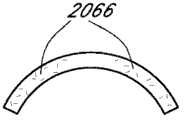
其它实施方案采用了不同的方式来控制掩盖物的光透过率。例如,掩盖物可以是经凝胶填充的盘,如图14所示。所述凝胶可以是水凝胶或胶原,或其它合适的材料,其与掩盖物材料具有生物相容性,并能被引入掩盖物内部。掩盖物中的凝胶可包括悬浮在凝胶中的颗粒物2066。合适的颗粒物实例包括钛颗粒、金颗粒和碳颗粒,如上文所述,或者可替代性地将其沉积在掩盖物的表面上。Other embodiments employ different means to control the light transmission of the mask. For example, the mask can be a gel-filled disc, as shown in FIG. 14 . The gel may be a hydrogel or collagen, or other suitable material, which is biocompatible with the mask material and which can be introduced inside the mask. The gel in the mask may include
掩盖物2034的材料可以是任何聚合物材料。当掩盖物2034应用于眼内植入物时,掩盖物2034的材料应当具有生物相容性。当使用凝胶时,该材料适于容纳凝胶。用于掩盖物2034的合适材料的实例包括优选的聚甲基丙烯酸甲酯或其它合适的聚合物或共聚物,如水凝胶等。当然,如上文所述,对于非凝胶填充材料,优选的材料可以是纤维材料,如涤纶网状物。The material of
图15和16示意一个实施方案,其中掩盖物2034w包含多个纳米机器(nanite)2068。“纳米机器”是适于选择性地透过或阻挡进入患者眼睛之光线的小颗粒结构。所述颗粒可具有在纳米技术应用中典型的非常小的的颗粒尺寸。纳米机器2068悬浮在凝胶中,或者插入掩盖物2034w的内部,如图15和16一般性显示。纳米机器2068可被预先设定以响应不同的光环境。15 and 16 illustrate an embodiment in which the
因此,如图15所示,在高光环境中,纳米机器2068转向并使其处于基本上完全地或选择性地阻挡进入眼睛之部分光线的位置。然而,在弱光环境下,此时期望更多的光线进入眼中,纳米机器可通过转向或使其处于允许更多的光线进入眼睛的位置来响应,如图16所示。Thus, as shown in FIG. 15, in high light environments, the
纳米装置或纳米机器是在实验室中生长的晶体结构。可对纳米机器进行处理使它们易于接受不同的刺激(例如光)。根据某些实施方案的一个方面,可向纳米机器赋予能量以响应于弱光和强光环境,它们以上文所述的方式转向,如图16一般性显示。Nanodevices or nanomachines are crystalline structures grown in the laboratory. Nanomachines can be manipulated to make them susceptible to different stimuli (such as light). According to an aspect of certain embodiments, nanomachines can be powered to respond to low and high light environments, they turn in the manner described above, as shown generally in FIG. 16 .
Smith等人,“Nanofabrication,”Physics Today,1990年2月,24-30页以及Craighead,“Nanoelectromechanical Systems”,Science,2000年11月24日,卷290,1502-1505页中描述了纳米尺度的装置和系统及其制造,二者通过引用整体并入本文中。Chen等人,“Diffractive Phase ElementsBased on Two-Dimensional Artificial Dielectrics”,Optics Letters,1995年1月15日,卷20,No.2,121-123页中公开了调整并使小尺寸颗粒的特性适于光学应用,其亦通过引用整体并入本文中。Smith et al., "Nanofabrication," Physics Today, February 1990, pp. 24-30 and Craighead, "Nanoelectromechanical Systems", Science, Nov. 24, 2000, Vol. 290, pp. 1502-1505 describe nanoscale The device and system, and their manufacture, are both incorporated herein by reference in their entirety. Chen et al., "Diffractive Phase Elements Based on Two-Dimensional Artificial Dielectrics", Optics Letters, Jan. 15, 1995, Vol. 20, No. 2, pp. 121-123 disclose adjusting and adapting the properties of small-sized particles to Optical applications, which is also incorporated herein by reference in its entirety.
在另一些实施方案中,可使用对光反应变色的材料作为掩盖物或附加于掩盖物。在强光条件下,对光反应变色材料可变暗,从而形成掩盖物来提高视近物的能力。在弱光条件下,对光反应变色材料变浅,其允许更多的光穿过并到达视网膜。在某些实施方案中,在弱光条件下,光反应变色材料变浅从而暴露眼内植入物的光学元件。In other embodiments, a photochromic material may be used as or in addition to the mask. Under strong light conditions, the photochromic material can be darkened to form a mask to improve the ability to see near objects. In low light conditions, the photochromic material becomes lighter, which allows more light to pass through and reach the retina. In certain embodiments, under low light conditions, the photoreactive chromic material becomes lighter thereby exposing the optics of the intraocular implant.
掩盖物可以具有不同程度的不透明度。例如,掩盖物可阻挡基本上全部的可见光或者阻挡部分的可见光。在掩盖物的不同区域,掩盖物的不透明度也可以是不同的。在某些实施方案中,掩盖物外边缘和/或内边缘的不透明度低于该掩盖物的中心区域。不同区域的不透明度可以是不连续过渡或梯度过渡的。不透明度过渡的其它实施方案可见于美国专利No.5,662,706、5,905,561和5,965,330中,其通过引用整体并入本文中。Masks can have varying degrees of opacity. For example, the mask can block substantially all visible light or block some visible light. The opacity of the mask can also be different in different areas of the mask. In certain embodiments, the outer and/or inner edges of the mask are less opaque than the central region of the mask. The opacity of different regions can be a discontinuous transition or a gradient transition. Other embodiments of opacity transitions can be found in US Patent Nos. 5,662,706, 5,905,561, and 5,965,330, which are incorporated herein by reference in their entirety.
在某些实施方案中,通过支持条2074和2072将掩盖物2034连接或固定到眼睛2010上,如图17所示,且一般性描述于美国专利No.4,976,732中,其通过引用整体并入本文中。In certain embodiments,
美国专利No.4,976,732(于1990年12月11日获得专利权)和美国专利申请No.10/854,033(于2004年5月26日提交)中公开了掩盖物的更多细节,二者通过引用整体并入本文中。Further details of the masks are disclosed in U.S. Patent No. 4,976,732 (patented December 11, 1990) and U.S. Patent Application No. 10/854,033 (filed May 26, 2004), both of which are incorporated by reference incorporated herein in its entirety.
与多焦点IOL、隐形眼镜或角膜治疗相比,包括本文所述的具有开口(例如针孔开口)的掩盖物的实施方案的优点在于:所有前述方法均将穿过开口的可用光线分成两个或更多个焦点,而本发明的掩盖物方法只有一个焦点(单焦点)。这种局限性迫使多焦点光学元件设计人员选择到达各个焦点的光量,还要处理未聚焦光线的效应(其总是存在于任何图像中)。为了尽可能地提高对无穷远距离(>6M)到40cm距离(正常阅读距离)的敏锐度,通常提供很少或不提供在中等距离聚焦的光线,结果,在这些距离的视觉敏锐度较差。An advantage of embodiments comprising a mask described herein having an opening (e.g., a pinhole opening) over multifocal IOLs, contact lenses, or corneal therapy is that all of the foregoing methods split the available light passing through the opening into two or more focal points, while the mask method of the present invention has only one focal point (single focal point). This limitation forces designers of multifocal optics to choose the amount of light that reaches each focal point, while also dealing with the effects of unfocused light, which is always present in any image. To maximize acuity at distances from infinity (>6M) to 40 cm (normal reading distance), little or no focused light at intermediate distances is usually provided, with consequent poor visual acuity at these distances .
然而,拥有增加聚焦深度的开口显著地提高远视患者对中等距离物体的视力。实际上,在中等距离时针孔开口的散焦模糊要小于近距离。这可见于图59中,该图是视觉敏锐度作为散焦之函数的折线图,其对具有开口之眼科装置的一个实施方案与两种市售的多焦点IOL进行了比较。尽管在非常近的距离(33cm,-3D)时多焦点IOL获得更好的视觉敏锐度,但在1m(-1D)到40cm(-2.5D)的中等距离范围内,所述针孔开口优于多焦点光学元件。However, having an aperture that increases the depth of focus significantly improves vision for objects at intermediate distances in hyperopic patients. In fact, the defocus blur of the pinhole opening is less at medium distances than at close distances. This can be seen in Figure 59, which is a line graph of visual acuity as a function of defocus comparing one embodiment of an ophthalmic device with an aperture to two commercially available multifocal IOLs. While multifocal IOLs achieve better visual acuity at very close distances (33cm, -3D), the pinhole opening is superior at intermediate distances from 1m (-1D) to 40cm (-2.5D). in multifocal optics.
视觉敏锐度是以logMAR测量的,并且是最小角分辨的对数,或是最小可见角间距的对数,其与视物距离无关。logMAR值为0表示20/20、6/6、或在特定距离为1的十进制敏锐度(decimal acuity),相当于Jaeger1(J1)的视近物敏锐度。散焦是以屈光度测量的,其是眼睛焦距(以米计)的倒数。因此,-1D的散焦表示眼睛聚焦在1/1=1m。标准(美国和欧洲)阅读距离为40cm,其为-2.5D的散焦(1/.4=2.5)。Visual acuity is measured as logMAR and is the logarithm of the minimum angular resolution, or the logarithm of the minimum visible angular separation, which is independent of visual distance. A logMAR value of 0 means 20/20, 6/6, or a decimal acuity of 1 at a specific distance, which is equivalent to the near-sight acuity of Jaeger1 (J1). Defocus is measured in diopters, which is the reciprocal of the focal length of the eye in meters. Thus, a defocus of -1 D means that the eye is focused at 1/1 = 1 m. The standard (US and European) reading distance is 40cm, which is -2.5D of defocus (1/.4=2.5).
III.抗UV的聚合物掩盖物材料III. UV resistant polymer masking material
由于掩盖物具有很高的表面积/体积比,并且在植入后暴露于大量的阳光下,因此掩盖物优选地包含良好的抗降解的材料,包括抗UV或其它波长光的暴露的材料。聚合物包括UV吸收组分(包括包含UV吸收添加剂的材料或由UV吸收单体(包括共聚单体)制成)可用于制造本文所公开的抗UV辐射降解的掩盖物。此类聚合物的实例包括但不限于在美国专利No.4,985,559和4,528,311中描述的聚合物,其通过引用整体并入本文中。在一个优选的实施方案中,掩盖物包含本身抗UV辐射降解的材料。在一个实施方案中,掩盖物包含一种聚合物材料,其很大程度上反射UV辐射或对其透明。除了能够抗UV辐射引起之降解的掩盖物以外,透镜体还可包括UV吸收组分,否则掩盖物可能不耐受UV辐射引起的降解,这是因为透镜体中的UV吸收组分可防止掩盖物被UV辐射而降解。Since the mask has a high surface area/volume ratio and is exposed to a large amount of sunlight after implantation, the mask preferably comprises materials that are well resistant to degradation, including materials that are resistant to exposure to UV or other wavelengths of light. Polymers including UV absorbing components, including materials comprising UV absorbing additives or made from UV absorbing monomers, including comonomers, can be used to make the masks disclosed herein that are resistant to degradation by UV radiation. Examples of such polymers include, but are not limited to, those described in US Patent Nos. 4,985,559 and 4,528,311, which are incorporated herein by reference in their entirety. In a preferred embodiment, the mask comprises a material which is inherently resistant to degradation by UV radiation. In one embodiment, the mask comprises a polymeric material that is largely reflective or transparent to UV radiation. In addition to a mask that is resistant to degradation by UV radiation, the lens body may also include a UV absorbing component that would otherwise not be resistant to degradation by UV radiation because the UV absorbing component in the lens body prevents masking substances are degraded by UV radiation.
或者,掩盖物可包括赋予抗降解效用的组分,或者可提供为赋予降解抗性的涂层(优选地至少在前表面上)。这些组分可通过例如将一种或多种抗降解聚合物与一种或多种其它聚合物混合而包括于其中。该混合物还可包含提供所需性能的添加剂,例如UV吸收材料。在一个实施方案中,混合物优选地包含总共约1~20(重量)%(包括约1~10(重量)%、5~15(重量)%和10~20(重量)%)的一种或多种抗降解聚合物。在另一实施方案中,混合物优选地包含总共约80~100(重量)%(包括约80~90(重量)%、85~95(重量)%和90~100(重量)%)的一种或多种抗降解聚合物。在另一实施方案中,所述混合物具有多种比例相当的材料,包含总共约40~60(重量)%(包括约50~60(重量)%和40~50(重量)%)的一种或多种抗降解聚合物。掩盖物还可包括不同类型抗降解聚合物的混合物,包括含有一种或多种通常对UV透明的或易于反射的聚合物以及一种或多种掺有UV吸收添加剂或单体的聚合物的混合物。这些混合物包括含有总共约1~20(重量)%(包括约1~10(重量)%、5~15(重量)%和10~20(重量)%)的一种或多种通常对UV透明的聚合物、总共约80~100(重量)%(包括约80~90(重量)%、85~95(重量)%、90~100(重量)%)的一种或多种通常对UV透明的聚合物,以及总共约40~60(重量)%(包括约50~60(重量)%、40~50(重量)%)的一种或多种通常对UV透明的聚合物。所述聚合物或聚合物混合物可以与下文讨论的其它材料混合,所述其它材料包括但不限于混浊剂、聚阴离子化合物和/或伤口愈合调节剂化合物。当与这些其它材料混合时,聚合物或聚合物混合物在构成掩盖物之材料中的量优选地约为50~99%(重量),包括约60~90%(重量)、约65~85%(重量)、约70~80%(重量)或约90~99%(重量)。Alternatively, the mask may comprise a component imparting resistance to degradation, or may be provided as a coating (preferably at least on the front surface) to impart resistance to degradation. These components can be included, for example, by mixing one or more degradation resistant polymers with one or more other polymers. The mixture may also contain additives that provide desired properties, such as UV absorbing materials. In one embodiment, the mixture preferably comprises a total of about 1 to 20% by weight (including about 1 to 10% by weight, 5 to 15% by weight and 10 to 20% by weight) of one or Various degradation resistant polymers. In another embodiment, the mixture preferably comprises a total of about 80-100% by weight (including about 80-90% by weight, 85-95% by weight and 90-100% by weight) of one or a variety of degradation-resistant polymers. In another embodiment, the mixture has a plurality of materials in comparable proportions comprising a total of about 40-60% by weight (including about 50-60% by weight and 40-50% by weight) of one or a variety of degradation-resistant polymers. The mask may also include a mixture of different types of degradation resistant polymers, including one or more polymers that are generally UV transparent or easily reflective and one or more polymers that incorporate UV absorbing additives or monomers. mixture. These mixtures include a total of about 1-20% by weight (including about 1-10% by weight, 5-15% by weight and 10-20% by weight) of one or more UV-transparent One or more of polymers, a total of about 80-100 (weight) % (including about 80-90 (weight) %, 85-95 (weight) %, 90-100 (weight) %) are usually UV transparent polymer, and a total of about 40-60 (weight) % (including about 50-60 (weight) %, 40-50 (weight) %) of one or more polymers that are generally UV transparent. The polymer or polymer blend may be mixed with other materials discussed below including, but not limited to, opacifying agents, polyanionic compounds, and/or wound healing modulator compounds. When mixed with these other materials, the amount of polymer or polymer mixture in the material making up the mask is preferably about 50-99% by weight, including about 60-90% by weight, about 65-85% (weight), about 70-80% (weight), or about 90-99% (weight).
优选的抗降解聚合物包括卤化聚合物。优选的卤化聚合物包括氟化聚合物,即聚合物具有至少一个碳-氟键,包括高度氟化的聚合物。本文使用的术语“高度氟化”取其广义含义,包括具有至少一个碳-氟键(C-F键)的聚合物,其C-F键的数目等于或大于碳-氢键(C-H键)的数目。高度氟化的材料还包括全氟化或完全氟化的材料、包含其它卤素取代基(如氯)的材料以及包含含氧或含氮官能团的材料。对于聚合物材料而言,键的数量可以通过参照构成聚合物之单体或重复单元来计算,在共聚物的情形中,可通过每个单体的相对量(基于摩尔数)来计算。Preferred degradation resistant polymers include halogenated polymers. Preferred halogenated polymers include fluorinated polymers, ie polymers having at least one carbon-fluorine bond, including highly fluorinated polymers. The term "highly fluorinated" is used herein in its broad sense to include polymers having at least one carbon-fluorine bond (C-F bond) equal to or greater than the number of carbon-hydrogen bonds (C-H bonds). Highly fluorinated materials also include perfluorinated or fully fluorinated materials, materials containing other halogen substituents such as chlorine, and materials containing oxygen- or nitrogen-containing functional groups. For polymeric materials, the number of linkages can be calculated by reference to the monomers or repeating units that make up the polymer, and in the case of copolymers, by the relative amount of each monomer (on a molar basis).
优选的高度氟化的聚合物包括但不限于:聚四氟乙烯(polytetrafluoroethylene,PFTE或

尽管高度氟化的聚合物是优选的,但是也可以使用具有一个或多个碳-氟键但不落在上文讨论的“高度氟化”的聚合物范围内的聚合物。这样的聚合物包括由一种或多种前文所述单体与乙烯、氟乙烯或其它单体构成的共聚物,从而形成C-H键数目多于C-F键数目的聚合物材料。也可以使用其它的氟化聚合物,如氟化聚酰亚胺。美国专利No.4,985,559和No.4,528,311描述了可用于一些应用中的其它材料(单独使用或者与氟化或高度氟化聚合物联用),二者通过引用整体并入本文中。Although highly fluorinated polymers are preferred, polymers having one or more carbon-fluorine bonds that do not fall within the scope of "highly fluorinated" polymers discussed above may also be used. Such polymers include copolymers of one or more of the aforementioned monomers with ethylene, vinyl fluoride, or other monomers to form polymeric materials having more C-H bonds than C-F bonds. Other fluorinated polymers, such as fluorinated polyimides, may also be used. Other materials that may be used in some applications (alone or in combination with fluorinated or highly fluorinated polymers) are described in US Patent Nos. 4,985,559 and 4,528,311, both of which are incorporated herein by reference in their entirety.
通过几个实例来举例说明前面定义的高度氟化。一种优选的抗UV聚合材料为聚偏氟乙烯(PVDF),其具有由式-(CF2-CH2)n-表示的结构。每个重复单元具有两个C-H键和两个C-F键。由于C-F键的数目等于或大于C-H键的数目,因此PVDF同聚物是“高度氟化”的聚合物。另一种材料是四氟乙烯/氟乙烯共聚物,由摩尔比为2∶1的这两种单体构成。无论所形成的共聚物是嵌段、随机或任何其它排列,从2∶1的四氟乙烯∶氟乙烯组成可以假设出包含两个四氟乙烯单元(每个单元具有四个C-F键)和一个氟乙烯单元(具有三个C-H键和一个C-F键)的“重复单元”。两个四氟乙烯和一个氟乙烯的全部键为9个C-F键和三个C-H键。由于C-F键的数目等于或大于C-H键的数目,所以认为该共聚物是高度氟化的。The previously defined high degree of fluorination is illustrated by a few examples. A preferred UV resistant polymeric material is polyvinylidene fluoride (PVDF), which has a structure represented by the formula -(CF2-CH2)n- . Each repeat unit has two CH bonds and two CF bonds. Since the number of CF bonds is equal to or greater than the number of CH bonds, PVDF homopolymers are "highly fluorinated" polymers. Another material is a tetrafluoroethylene/fluoroethylene copolymer consisting of these two monomers in a 2:1 molar ratio. Whether the resulting copolymer is block, random, or any other arrangement, it can be assumed from the 2:1 tetrafluoroethylene:fluoroethylene composition to contain two tetrafluoroethylene units (each unit has four CF bonds) and one A "repeating unit" of vinyl fluoride units (with three CH bonds and one CF bond). The total bonds of two tetrafluoroethylenes and one fluoroethylene are 9 CF bonds and three CH bonds. Since the number of CF bonds is equal to or greater than the number of CH bonds, the copolymer is considered highly fluorinated.
某些高度氟化的聚合物(如PVDF)具有一种或多种期望的特征,例如,与其非氟化或较低度氟化的对应聚合物相比,具有相对的化学惰性和相对较高的UV透明度。虽然本申请人不旨在受理论的束缚,但推测氟的电负性可能赋予具有较大数目之C-F键的材料以期望的特性。Certain highly fluorinated polymers, such as PVDF, possess one or more desirable characteristics, for example, relative chemical inertness and relatively high UV transparency. While the applicants do not intend to be bound by theory, it is speculated that the electronegativity of fluorine may confer desirable properties on materials with larger numbers of C-F bonds.
在一些优选实施方案中,制造掩盖物的至少一部分高度氟化的聚合物材料包含混浊剂,其赋予所需程度的不透明度。在一个实施方案中,混浊剂提供了足够的不透明度以产生本文所述的景深的改进,例如与透光开口结合时。在一个实施方案中,混浊剂使材料不透明。在另一实施方案中,混浊剂阻止约90%或更多的入射光透过。在另一实施方案中,混浊剂使材料不透明。在另一实施方案中,混浊剂阻止约80%或更多的入射光透过。优选的混浊剂包括但不限于:有机染料和/或色素,优选黑色的,例如偶氮染料、苏木黑、苏丹黑染料;无机染料和/或色素,包括金属氧化物如氧化铁黑及钛铁黑(ilminite)、碳化硅和碳(例如,炭黑、亚微米级碳粉等)。上述材料可以单独使用或者与一种或多种其它材料联合使用。所述混浊剂可应用于掩盖物的一个或多个表面的全部或部分表面上,或者其可以与聚合物材料混合或组合(例如在聚合物熔融相期间混合)。虽然可以使用任何前述材料,但是发现碳尤其有用,这是因为碳不像有机染料一样随着时间褪色,并且它还通过吸收UV辐射而有助于提高材料的UV稳定性。在一个实施方案中,可将碳与聚偏氟乙烯(PVDF)或其它包含高度氟化聚合物的聚合物混合,从而使碳占所得组合物重量的约2%至约20%,包括占所得组合物重量的约10%至约15%(包括约12%、约13%和约14%)。In some preferred embodiments, at least a portion of the highly fluorinated polymeric material from which the mask is made comprises a clouding agent which imparts a desired degree of opacity. In one embodiment, the opacifying agent provides sufficient opacity to produce the depth of field improvements described herein, for example when combined with a light-transmitting opening. In one embodiment, the opacifying agent renders the material opaque. In another embodiment, the opacifying agent prevents transmission of about 90% or more of incident light. In another embodiment, the opacifying agent renders the material opaque. In another embodiment, the opacifying agent prevents transmission of about 80% or more of incident light. Preferred clouding agents include, but are not limited to: organic dyes and/or pigments, preferably black, such as azo dyes, hematoxylin, Sudan black dyes; inorganic dyes and/or pigments, including metal oxides such as iron oxide black and titanium Iron black (ilminite), silicon carbide, and carbon (eg, carbon black, submicron carbon powder, etc.). The above materials may be used alone or in combination with one or more other materials. The clouding agent may be applied to all or part of one or more surfaces of the mask, or it may be mixed or combined with the polymeric material (eg, mixed during the polymer melt phase). While any of the foregoing materials may be used, carbon has been found to be particularly useful because it does not fade over time like organic dyes, and it also helps to increase the UV stability of the material by absorbing UV radiation. In one embodiment, the carbon may be mixed with polyvinylidene fluoride (PVDF) or other polymers comprising highly fluorinated polymers such that the carbon constitutes from about 2% to about 20% by weight of the resulting composition, including From about 10% to about 15% (including about 12%, about 13% and about 14%) by weight of the composition.
某些混浊剂(例如色素)的加入使掩盖物的部分变黑、变暗或变混浊,与不包含此类试剂的掩盖物材料相比,其可使掩盖物更大程度地吸收入射辐射。由于含有或包括所述色素的基质聚合物可由于所吸收的辐射而发生降解,因此优选所述掩盖物(其较薄且具有大的表面积,使其易受环境降解)由本身抗降解(例如,抗UV辐射降解)的或者通常对UV辐射透明或不吸收UV辐射的材料制成。使用高UV抗性和降解抗性的材料(例如PVDF,其对UV辐射高度透明)允许更大的混浊剂选择灵活性,由于选择特定混浊剂可能导致的聚合物破坏被大大降低了。The addition of certain opacifying agents, such as pigments, to darken, darken, or cloud parts of the mask can cause the mask to absorb incident radiation to a greater extent than mask materials that do not contain such agents. Since the matrix polymer containing or comprising the pigment may degrade due to absorbed radiation, it is preferred that the mask (which is thin and has a large surface area making it susceptible to environmental degradation) is inherently resistant to degradation (e.g. , resistant to UV radiation degradation) or generally made of UV radiation transparent or non-absorbing materials. The use of materials with high UV resistance and degradation resistance (such as PVDF, which is highly transparent to UV radiation) allows greater flexibility in clouding agent selection, and possible polymer damage due to selection of a specific clouding agent is greatly reduced.
可预期前述降解抗性构造之实施方案的多种变化形式。在一种变化形式中,掩盖物几乎完全由不易被UV降解的材料制成。例如,该掩盖物可以由金属、高度氟化的聚合物、碳(例如,石墨烯、纯碳)或者其它类似的材料制成。美国专利申请11/000,562(于2004年12月1日提交,名称为“制造眼内植入物的方法”)和美国专利申请11/107,359(于2005年4月14日提交,名称为“制造眼内植入物的方法”)中详细地讨论了含有金属的掩盖物的构造,二者通过引用整体并入本文中。如上下文使用地,“完全”取其广义含义,其允许在如上文讨论的混浊剂中存在一些非功能性材料(例如,杂质)。在另一些实施方案中,掩盖物可包括材料的组合。例如,在一种变化形式中,掩盖物主要由任意可植入材料制成并涂覆有抗UV材料。在另一种变化形式中,掩盖物包括足够浓度的一种或多种UV降解抑制剂和/或一种或多种抗UV降解的聚合物,从而在正常使用条件下使掩盖物针对降解而言保持足够的功能性,从而保持至少约5年(优选地至少约10年、在某些实施方案中至少约20年)的医学有效性。Numerous variations of the foregoing embodiments of degradation-resistant constructs are contemplated. In one variation, the mask is made almost entirely of a material that is not easily degraded by UV. For example, the mask can be made of metal, highly fluorinated polymers, carbon (eg, graphene, pure carbon), or other similar materials. U.S. Patent Application 11/000,562 (filed December 1, 2004, entitled "Method of Manufacturing an Intraocular Implant") and U.S. Patent Application 11/107,359 (filed April 14, 2005, entitled "Making The construction of metal-containing masks is discussed in detail in "Methods of Intraocular Implants"), both of which are incorporated herein by reference in their entirety. As used in context, "completely" is taken in its broad sense allowing for some non-functional material (eg, impurities) to be present in the clouding agent as discussed above. In other embodiments, the mask may comprise a combination of materials. For example, in one variation, the mask is made essentially of any implantable material and is coated with a UV resistant material. In another variation, the mask includes one or more UV degradation inhibitors and/or one or more UV degradation resistant polymers in sufficient concentration such that the mask is resistant to degradation under normal use conditions. Sufficient functionality is maintained to maintain medical effectiveness for at least about 5 years, preferably at least about 10 years, and in certain embodiments at least about 20 years.
图23是利用掩盖物制造掩盖型眼内植入物之方法的流程图,所述掩盖物包含高度氟化的聚合物和混浊剂。图23的方法包括制造含有高度氟化的聚合物和混浊剂的掩盖物的第一方法3014,以及利用由所述第一方法3014制得之掩盖物制造眼内植入物的第二方法3026。23 is a flowchart of a method of making a masked intraocular implant using a mask comprising a highly fluorinated polymer and an opacifying agent. The method of FIG. 23 includes a
在步骤3000中,通过使用加热将聚偏氟乙烯(PVDF)颗粒溶于溶剂(例如二甲基乙酰胺(dimethyl acetamide,DMAC或DMA))中直至PVDF完全溶解来制备液体形式的聚合物。在一个实施方案中,该溶液可混合至少12小时以确保PVDF完全溶解。在步骤3200中,使用高速剪切混合器将PVDF/DMAC溶液与混浊剂(例如染料或炭黑)混合。在一个实施方案中,炭黑占所得组合物重量的13%,而PVDF占所得组合物重量的87%。在步骤3300中,任选地在高速研磨器(例如Eiger高速研磨器)中研磨PVDF/炭黑溶液,以破碎溶液中的大块碳聚集物。可使用研磨器再次研磨PVDF/炭黑溶液,以进一步破碎碳聚集物。在步骤3400中,将所得溶液施加到硅晶片上以在硅盘(silicon disk)上形成聚合物膜。此时,将约55g PVDF/炭黑溶液倒入分配筒中用于施加在硅晶片上。将硅盘置于离心浇铸机(spin casting machine)上,并用分配筒以环形模式将PVDF/炭黑溶液施加在硅晶片上,盘中心直径1”的地方留空。设定旋转周期以使PVDF/炭黑溶液分散在硅盘上,形成均匀的10微米厚的膜。聚合物膜也可以通过沉积、喷涂等方法施加到硅晶片上。将经涂覆硅盘置于热板上以蒸发DMAC。在步骤3500中,将经涂覆的硅晶片置于准分子激光器下。启动激光并使用激光制备激光切割掩盖物。利用激光切割掩盖物,大约150种掩盖物图案被激光加工到PVDF/炭黑膜中。所述掩盖物图案还可以使用冲压工艺、电子束、蚀刻等来形成。所述掩盖物图案需使得从硅盘边缘延伸约5mm的处的材料未被利用。在激光加工过程中,可将硅盘浸于氮气中以冷却表面。在步骤3600中,使用剃刀刀片将激光加工的掩盖物从硅盘上取下。任选步骤可包括将激光加工的掩盖物置于成形模具中。该模具可具有任何期望的形状,例如平模具、凸模具、凹模具或形状更加复杂的模具。在一种技术中,可将掩盖物置于成型模具的下半部。可将成型模具的上半部置于所述掩盖物的顶部,并可将所述模具放置在160℃烘箱中。然后将模具加热烘烤以形成掩盖物。可将模具在约160℃烘烤约2小时。2小时后,将烘箱温度降至约30℃,将掩盖物烘烤约两小时或直至烘箱温度降至低于约40℃。In
在步骤3016中,将在第一方法3014中制得的嵌入物(例如掩盖物)放置在模具中。在一个实施方案中,将硅酮或其它透镜材料注入模具中以包绕嵌入物。在步骤3018中,使硅酮固化以形成植入体。在步骤3020中,将眼内植入物抛光,在步骤3022中,将植入体从模具中取出。在步骤3024中,将一个或多个袢连接(例如键合)至植入体以形成眼内植入物。针对三件型IOL设计可包括步骤3024,但该步骤可能对于其设计来说不是必需的。在某些实施方案中,在注入过程期间即形成植入体的一个或多个袢。例如,可对植入体进行车削,则袢从单件磨出来。随后,可对眼内植入物进行检查(例如,外观、屈光度、分辨率)。In
IV.配置用于减少可见衍射图案的掩盖物IV. Masks Configured to Reduce Visible Diffraction Patterns
可使用前述的多种掩盖物提高患者的聚焦深度。以下讨论另外一些不同的掩盖物实施方案。下述的一些实施方案包括穿透掩盖物环形区域的透光孔,以改变环形区域阻挡的光量。穿透掩盖物的透光孔可以改善患者的弱光或低光视力。在某些透光孔的排列方案中,透光孔可以产生衍射图案,其影响本文所述掩盖物的视力改善效果。因此,本文所述的某些掩盖物包括不产生衍射图案的透光孔或者不干扰该掩盖物实施方案的视力提高效果。The patient's depth of focus can be increased using a variety of masks as previously described. Some other alternative mask embodiments are discussed below. Some of the embodiments described below include light apertures through the annular region of the mask to vary the amount of light blocked by the annular region. Light holes penetrating the mask can improve patients' low-light or low-light vision. In certain arrangements of the apertures, the apertures can create a diffractive pattern that affects the vision-improving effect of the coverings described herein. Accordingly, certain coverings described herein include light-transmissive apertures that do not create diffractive patterns or interfere with the vision-enhancing benefits of embodiments of the covering.
图18-19显示掩盖物2100的实施方案,其配置用于增加远视患者眼睛的聚焦深度。除了以下区别之外,掩盖物2100类似于前文所述的掩盖物。掩盖物2100可以由本文讨论的材料(包括上文讨论的那些材料)制造。而且,掩盖物2100可以通过任何合适的方法制造。掩盖物2100被配置应用于IOL。18-19 illustrate an embodiment of a
在一个实施方案中,掩盖物2100包括主体2104,其具有前表面2108和后表面2112。主体2104可以由任何合适的材料制备,包括至少一种开孔泡沫材料(open foam material)、膨胀的固体材料和基本上不透明的材料。在另一些实施方案中,用于制备主体2104的材料具有较高的水含量。在其它实施方案中,可用于制备主体2104的材料包括聚合物(例如,PMMA、PVDF、聚丙烯、聚碳酸酯、PEEK、聚乙烯、丙烯酸共聚物(例如,疏水性或亲水性)、聚苯乙烯、PVC、聚砜)、水凝胶、聚硅酮、金属、金属合金或碳(例如,石墨烯、纯碳)。In one embodiment, the
在一个实施方案中,掩盖物2100包括透光孔排列方案2116。该透光孔排列方案2116可包括一系列孔2120。所述孔2120仅显示于掩盖物2100的一部分上,但是优选地在一个实施方案中孔2120位于整个主体2104上。在一个实施方案中,孔2120以六边形排列(hex pattern),其以一系列位置2120′示意于图20A中。如下文讨论地,可确定一系列位置,随后用于在掩盖物2100上形成一系列孔2120。掩盖物2100具有外周2124,其限定了主体2104的外边缘。在一些实施方案中,掩盖物2100包括开口2128(其至少部分地被外周2124包绕)和非透过部分2132(其位于外周2124和开口2128之间)。In one embodiment,
优选地,掩盖物2100是对称的,例如沿掩盖物轴2136对称。在一个实施方案中,掩盖物2100的外周2124是圆形的。在一个实施方案中,掩盖物的直径范围一般为约3mm至约8mm,常常为约3.5mm至约6mm以及小于约6mm。在另一个实施方案中,所述掩盖物是圆形的,其直径范围为4~6mm。在另一个实施方案中,所述掩盖物2100是圆形的,其直径小于4mm。在另一个实施方案中,外周2124的直径约为3.8mm。在一些实施方案中,不对称的或不沿掩盖物轴对称的掩盖物提供了益处,例如使掩盖物能够定位或保持在眼睛解剖结构中选定的位置。Preferably,
掩盖物2100的主体2104可配置成与特定眼内透镜设计相偶联(厚度减小的设计或常规设计)。例如,当掩盖物2100与具有曲率的特定IOL偶联时,主体2104可提供成具有沿掩盖物轴2136相应量的曲率(对应于所述曲率)。同样,主体2104可提供为具有适应IOL过渡区的相应形状。The
在一些实施方案中,掩盖物2100具有期望量的光学聚焦能力。可通过设置前表面2108和后表面2112中至少一个的曲率来提供光学聚焦能力。在一个实施方案中,所述前表面2108和后表面2112具有不同值的曲率。在该实施方案中,该掩盖物2100的厚度从外周2124到开口2128是有所不同的。In some embodiments,
在一个实施方案中,主体2104的前表面2108和后表面2112之一基本上是平面的。在一个平面的实施方案中,沿平表面几乎不能或不能测出均一的曲率。在另一个实施方案中,所述前表面2108和后表面2112均基本上是平面的。通常,掩盖物2100的主体2104的厚度从大于零至约0.5mm的范围。在另一个实施方案中,掩盖物2100的厚度2138约为0.25mm。与非平面掩盖物相比,基本上平的掩盖物具有若干优点。例如,制造基本上平的掩盖物比制造具有特定曲率的掩盖物更加容易。特别地,可省去向掩盖物2100中引入曲面的步骤。In one embodiment, one of the
开口2128被配置用于透过基本上所有沿掩盖物轴2136的入射光。非透过部分2132包绕开口2128的至少一部分,并且基本上阻挡其上的入射光透过。如上述所讨论地,开口2128可以是穿透主体2104或基本上透光(例如,透明的)之部分的孔。掩盖物2100的开口2128通常位于掩盖物2100之外周2124界限之内。所述开口2128可采用任何合适的配置,如上文描述的那些。
在一个实施方案中,开口2128基本上是圆形的且基本上位于掩盖物2100的中心。所述开口2128的尺寸可以是有效提高远视患者眼睛聚焦深度的任意尺寸。特别地,所述开口2128的尺寸取决于掩盖物在眼中的位置(例如,距视网膜的距离)。例如,在一个实施方案中,在眼睛的眼内空间中,开口2128可以是圆形的,其直径小于约2mm。在另一个实施方案中,开口的直径为约1.1mm至约1.6mm。在另一个实施方案中,开口2128是圆形的,其直径为约1.6mm或更小。在另一个实施方案中,开口的直径约为mm。大多数开口的直径为约0.85mm至约2.2mm,常常为约1.1mm至约1.7mm。In one embodiment, the
在某些实施方案中,开口2128具有光学聚焦能力和/或折射特性。例如,所述开口2128可包括光学元件并且可具有光学聚焦能力(例如正或负的光学聚焦能力)。在某些实施方案中,开口2128可矫正眼睛的屈光不正。In certain embodiments, the
非透光部分2132被配置为阻止辐射能透过掩盖物2100。例如,在一个实施方案中,非透光部分2132阻止入射辐射能中至少一部分光谱的几乎所有透过。在一个实施方案中,所述非透光部分2132被配置为阻止基本上全部可见光(例如电磁光谱中人眼可见的辐射能)的透过。在一些实施方案中,非透光部分2132可以基本上阻止人眼可见范围之外的辐射能的透过。The
如上文讨论地,阻止光透过非透光部分2132降低了到达视网膜和中央凹(fovea)的光量,这些光不会在视网膜和中央凹汇聚形成清晰图像。如上文讨论地,开口2128的尺寸使得从中透过的光基本上在视网膜或中央凹上汇聚。因此,眼睛获得了比没有掩盖物2100时更清晰的图像。As discussed above, preventing light from passing through the
在一个实施方案中,非透光部分2132阻止至少约90%的入射光透过。在另一个实施方案中,非透光部分2132阻止至少约95%的入射光透过。掩盖物2100的非透光部分2132可配置成基本上不透明的以阻止光透过。本文所用术语“不透明”旨在表示透过不超过约2%的入射可见光。在一个实施方案中,将主体2104的至少一部分设置成针对其上超过99%的入射光为不透明的。In one embodiment, the
如上文讨论地,非透光部分2132可配置为阻止光透过而非吸收入射光。例如,可以将掩盖物2100制成易于反射的或制成以更复杂之方式与光相互作用的,如在美国专利No.6,554,424(于2003年4月29日获权)中讨论地,其通过引用整体并入本文中。As discussed above, the
如上文讨论地,掩盖物2100还具有透光孔,在一些实施方案中,其包括一系列孔2120。一系列孔2120(或其它光透过结构)的存在可影响光透过所述非透光部分2132,其通过潜在地允许更多光线穿过掩盖物2100来实现。在一个实施方案中,所述非透光部分2132被配置用以吸收约98%或更多的、穿过不带孔2120之掩盖物2100的入射光。所述一系列孔2120的存在使得更多的光穿过非透光部分2132,从而使非透光部分2132只阻止约95%的入射光穿过非透光部分2132。由于允许更多的光穿过非透光部分到达视网膜,孔2120可降低开口2128对眼睛聚焦深度的益处。As discussed above, the
如上文讨论地,图18A所示的掩盖物2100之孔2120可定位于掩盖物2100上的任何位置。在下文所述的另一些掩盖物实施方案中,将基本上所有透光孔定位在掩盖物的一个或多个区域。As discussed above, the
图18A所示的孔2120至少部分地延伸于掩盖物2100之前表面2108和后表面2112之间。在一个实施方案中,每个孔2120包括孔入口2160和孔出口2164。所述孔入口2160邻近于掩盖物2100的前表面2108。孔出口2164邻近于掩盖物2100后表面2112。在一个实施方案中,每个孔2120在掩盖物2100的前表面2108和后表面2112之间的整个距离延伸。
在一个实施方案中,孔2120的直径为约0.002mm至约0.050mm。在某些实施方案中,所述孔2120的直径约为0.005mm或更大。在另一个实施方案中,孔直径约为0.020mm。在另一个实施方案中,孔直径为约0.025mm。在另一个实施方案中,孔直径约为0.027mm。在另一个实施方案中,孔2120的直径约为0.020mm至约0.029mm。在一个实施方案中,选定所述一系列孔2120中孔的数目,从而使孔2100之孔入口2140的总表面积约占掩盖物2100前表面2108之表面积的5%或更多。在另一个实施方案中,选定孔2120的数目,从而使全部孔2120之孔出口2164的总表面积约占掩盖物2100后表面2112之表面积的5%或更多。在另一个实施方案中,选定孔2120的数目,从而使全部孔2120之孔出口2164的总表面积约占掩盖物后表面2112之表面积的5%或更多,并且全部孔2120之孔入口2140的总表面积约占掩盖物2100前表面2108之表面积的5%或更多。在另一个实施方案中,所述一系列孔2120可包含约1600个微穿孔(microperforation)。在另一个实施方案中,所述一系列孔2120包含约8400个微孔。In one embodiment, the
每个孔2120可具有相对均一的横截面积。在一个实施方案中,每个孔2120的截面形状基本上是圆形的。每个孔2120可包括延伸于前表面2108和后表面2112之间的圆柱体。Each
在一些实施方案中,孔2120的相对位置是有用的。如上所讨论地,掩盖物2100的孔2120是以六个为一组的,例如排列成六边形图案。特别地,在本实施方案中,每个孔2120与相邻孔2120的间距基本一致(有时称为“孔间距(hole pitch)”。在一个实施方案中,孔间距约为0.045mm。In some embodiments, the relative location of
采用六边形的图案,对称线之间的角度约为43°。任意两个相邻孔之间的间隔通常为约30μm至约100μm(在一个实施方案中,为约43μm)。所述孔直径通常为约2μm至约100μm(在一个实施方案中,为约20μm)。本领域技术人员通过本文公开的内容应该理解,所述光透过是孔面积之和的函数。Using a hexagonal pattern, the angle between the lines of symmetry is approximately 43°. The spacing between any two adjacent wells is typically from about 30 μm to about 100 μm (in one embodiment, about 43 μm). The pore diameter is typically from about 2 μm to about 100 μm (in one embodiment, about 20 μm). Those skilled in the art should understand from the content disclosed herein that the light transmission is a function of the sum of the hole areas.
由于存在透光孔排列2116,因此可影响视物效果。例如,在一些情况下,以六个为一组排列的孔2120可产生患者可见的衍射图案。例如,采用六边形图案的孔2120,患者可观察到多个点(例如六个点)包绕中心光。Due to the presence of the
可采用多种技术产生有利的透光孔排列,使得衍射图案和其它不利视物效果基本不会干扰掩盖物的其它有益视物效果。在一个实施方案中,当可观察到衍射效果时,将透光孔排列成均匀地使衍射光分散到整个图像,从而消除可见的光点。在另一个实施方案中,透光孔采用基本消除衍射图案或将所述衍射图案推至图像周围的排列方案。A variety of techniques can be used to create an advantageous arrangement of apertures such that diffraction patterns and other adverse visual effects do not substantially interfere with other beneficial optical effects of the mask. In one embodiment, when diffractive effects are observable, the apertures are arranged to evenly disperse the diffracted light throughout the image, thereby eliminating visible spots of light. In another embodiment, the apertures are arranged in an arrangement that substantially eliminates the diffraction pattern or pushes the diffraction pattern around the image.
图20B-20C显示孔2220’图案的两个实施方案,其可被应用于基本上类似于掩盖物2100的掩盖物。具有图20B-20C之孔图案的孔2220’彼此之间的孔间距是随机的。在如下文讨论的另一些实施方案中,孔彼此之间的间距是不均一的,但不是随机的。在一个实施方案中,孔2220’具有基本上一致的形状(具有基本一致的横截面面积的圆柱状轴)。图20C示意由随机间距分隔的一系列孔2220’,其中孔密度大于图20B中的孔密度。通常,掩盖物主体上孔所占百分比越高,其允许透过掩盖物的光越多。一种提供更高百分比之孔面积的方法是增加孔密度。增加孔密度也可允许较小的孔来实现与较低密度、较大孔相同的光透过。Figures 20B-20C show two embodiments of hole 2220' patterns that can be applied to a mask substantially similar to
图21A显示另一种掩盖物2200a的一部分,该掩盖物与掩盖物2100基本上类似(除了下述区别以外)。掩盖物2200a可由本文讨论的材料制造,包括上文讨论的那些材料。掩盖物2200a可采用任何合适的方法制造,如本文讨论的方法以及这些方法的变通方式。掩盖物2200a具有透光孔排列样式2216a,其包括一系列孔2220a。实质性部分的孔2220a具有不一致的尺寸。孔2220a可以具有一致的截面形状。在一个实施方案中,孔2220a截面形状基本上为圆形。孔2220a的形状可以是圆形的并且从孔入口到孔出口具有相同的直径,但在至少一个方面是不一致的(例如尺寸)。优选地,以随机的方式使实质性部分的孔的尺寸有所不同。在另一个实施方案中,孔2220a的尺寸是不均一的(例如,随机的)并且间距不一致(例如,随机的)。Figure 21A shows a portion of another
图21B显示另一种掩盖物2200b的实施方案,该掩盖物与掩盖物2100基本上类似(除了下述区别以外)。掩盖物2200b可以由本文讨论的材料制造。另外,掩盖物2200b可采用任何合适的方法制造,如本文讨论的方法以及这些方法的变通方式。掩盖物2200b包括主体2204b。掩盖物2200b具有透光孔排列样式2216b,其包括一系列具有非均一面取向的孔2220b。特别地,每个孔2220b具有孔入口,其可位于掩盖物2200b的前表面。孔入口的面定义为掩盖物2200b的主体2204b包绕该孔入口的部分。所述面的形状是前表面上孔入口的形状。在一个实施方案中,大多数或全部的面具有细长的形状,例如具有长轴和垂直于长轴之短轴的椭圆形状。所述面可具有基本上均一的形状。在一个实施方案中,所述面的取向是不均一的。例如,实质性部分的面可具有非均一的取向。在一种排列样式中,实质性部分的面具有随机的取向。在一些实施方案中,所述面具有非均一(例如,随机)的形状和非均一(例如,随机)的取向。FIG. 21B shows another embodiment of a
可提供在至少一个方面有所变化的其它实施方案,包括上述一系列孔的一个或多个方面,以降低孔产生可见衍射图案或者减少可由具开口之掩盖物(如上文所述的那些)提供的视觉改进的图案的趋势。例如,在一个实施方案中,至少实质性部分的孔的孔径、形状、取向可随机改变或可以是非均一的。掩盖物还可具有以下特征,即改变一系列孔的孔径、形状、取向和间距中至少一个以降低孔产生可见衍射图案的趋势。在某些实施方案中,通过采用具有第一孔径、形状或间距的一系列孔和具有不同于所述第一孔径、形状或间距的第二孔径、形状或间距的至少另一系列孔,来降低孔产生可见衍射图案的趋势。在另一些实施方案中,掩盖物的特征在于所述一系列孔之实质性部分的孔径、形状、取向和间距中至少一种与至少另一系列孔之孔径、形状、取向和间距中至少一种不同,以降低孔产生可见衍射图案的趋势。在另一些实施方案中,孔不规则定位。例如,使孔不规则定位以使尽可能少地产生由于光穿过孔而产生的可见假象。Other embodiments may be provided that vary in at least one aspect, including one or more aspects of the series of apertures described above, to reduce the visible diffraction pattern produced by the apertures or to reduce the diffraction pattern that may be provided by masks with openings such as those described above. A visually improved pattern trend. For example, in one embodiment, at least a substantial portion of the pores may vary randomly in size, shape, orientation or may be non-uniform. The mask can also be characterized by varying at least one of the aperture, shape, orientation and spacing of the series of apertures to reduce the tendency of the apertures to produce a visible diffraction pattern. In certain embodiments, by employing a series of holes having a first pore size, shape or spacing and at least another series of holes having a second pore size, shape or spacing different from said first pore size, shape or spacing, Reduces the tendency of holes to produce visible diffraction patterns. In other embodiments, the mask is characterized by at least one of the pore size, shape, orientation and spacing of a substantial portion of the series of pores and at least one of the pore size, shape, orientation and spacing of at least another series of pores. different to reduce the tendency of the holes to produce visible diffraction patterns. In other embodiments, the pores are irregularly located. For example, the apertures are positioned irregularly to create as few visible artifacts as possible due to light passing through the apertures.
图22显示另一种掩盖物2300的实施方案,其基本上类似于上述的任何掩盖物(除了下述区别以外)。掩盖物2300可以用本文讨论的材料制造。而且,掩盖物2300可以由任何合适的方法制造,如本文讨论的方法以及这些方法的变通方式。该掩盖物2300包括主体2304。主体2304具有外周区域2305、内周区域2306和孔区2307。孔区2307位于外周区域2305和内周区域2306之间。当开口不是贯通孔时(下文讨论),主体2304还可以包括开口区域2328。所述掩盖物2300还包括透光孔排列样式2316。在一个实施方案中,透光孔排列样式包括一系列孔。至少实质性部分孔(例如,全部的孔)位于孔区2307中。如上,为了简化图案,仅仅显示了一部分透光孔的排列样式2316。应当理解,孔排列样式可以遍布于整个孔区2307。Figure 22 shows another embodiment of a
外周区域2305可以从掩盖物2300的外周2324延伸到掩盖物2300选定的外圆周2325。掩盖物2300的选定外圆周2325位于距离掩盖物2300外周2324选定的径向距离的位置。在一个实施方案中,掩盖物2300所选定的外圆周2325位于离掩盖物2300外周2324约0.05mm的位置。
内周区域2306可以从内部位置(例如,与掩盖物2300的开口2328相邻的内周2326)延伸到掩盖物2300选定的内圆周2327。掩盖物2300所选定的内圆周2327位于距离掩盖物2300内周2326选定的径向距离的位置。在一个实施方案中,掩盖物2300所选定的内圆周2327位于离掩盖物2300内周2326约0.05mm的位置。
掩盖物2300可以是如下方法的产品,所述方法包括随机选择一系列位置并在掩盖物2300对应的位置处形成孔。如下文进一步讨论地,所述方法还可包括确定所选位置是否符合一个或多个标准。例如,一个标准禁止所有(至少大部分或至少绝大部分)的孔在对应于内周或外周区域2305、2306处形成。另一标准禁止所有(至少大部分或至少绝大部分)的孔彼此过于靠近。例如,这样的标准可以用于确保壁厚(例如相邻孔之间的最短距离)不小于预定量。在一个实施方案中,壁厚不小于约20μm。
在图22所示实施方案的一种变通方式中,外周区域2305被去掉了,而孔2307区域从内周区域2306延伸到外周2324。在图50所示的另一个实施方案的变通方式中,内周区域2306被去掉了,而孔2307区域从外周区域2305延伸到内周2326。In a variation of the embodiment shown in FIG. 22 , the
在前述任何一种掩盖物的实施方案中,掩盖物的主体可以由一种选定的材料制成,该材料基本上防止了如上文所述的不利光学效应(例如衍射)。在多种实施方案中,掩盖物是由下列材料制成的:开孔泡沫材料、硅酮、热固塑料(thermoset)和热弹性聚合物(例如,PVDF、PMMA)、金属、Teflon和碳。在另一个实施方案中,掩盖物由可延展的固体材料制成。In any of the foregoing mask embodiments, the body of the mask may be formed from a material selected to substantially prevent adverse optical effects (eg, diffraction) as described above. In various embodiments, the mask is made of open cell foam, silicone, thermoset and thermoelastic polymers (eg, PVDF, PMMA), metal, Teflon, and carbon. In another embodiment, the mask is made of a malleable solid material.
如上文关于图20B和20C的讨论,可有利地提供各种随机的孔图案。在一些实施方案中,提供规则的孔图案可能就足够了。可通过任何合适的技术来提供在某些方面不均一的非均一的孔。As discussed above with respect to Figures 20B and 20C, various random hole patterns can advantageously be provided. In some embodiments, it may be sufficient to provide a regular pattern of holes. Non-uniform pores that are not uniform in some respect may be provided by any suitable technique.
在一种技术的第一步中,生成一系列位置2220’。位置2220’是一系列坐标,其可包括非均一图案或规则图案。所述位置2220’可以随机地生成,或者可以通过数学关系得出(例如,以固定的间距分隔或者以可用数学方法定义的量来分隔)。在一种实施方案中,选择所述位置使相隔一定的间距或间隔,并且可以是以六个为一组的。In a first step of one technique, a series of locations is generated 2220'. Location 2220' is a series of coordinates, which may include a non-uniform pattern or a regular pattern. The locations 2220' may be randomly generated, or may be derived from a mathematical relationship (eg, separated by a fixed interval or separated by a mathematically definable amount). In one embodiment, the locations are selected to be spaced or spaced apart, and may be in groups of six.
在第二步中,修改一系列位置2220’的子位置以保持掩盖物的性能特征。所述性能特征可以是掩盖物的任何性能特征。例如,所述性能特征可以涉及掩盖物的结构完整性。当一系列位置2220’随机选择时,修改子位置的方法可使产生的掩盖物中孔图案成为“伪随机”图案。In a second step, the sub-locations of a series of locations 2220' are modified to maintain the performance characteristics of the cover. The performance characteristic may be any performance characteristic of the mask. For example, the performance characteristics may relate to the structural integrity of the covering. When the series of positions 2220' are chosen randomly, the method of modifying the sub-positions can make the hole pattern in the resulting mask a "pseudo-random" pattern.
当在第一步中选择以六个为一组的图案的位置(如图20A所示的位置2120’)时,子位置可以相对于第一步中选择的初始位置进行移动。在一个实施方案中,将子位置中的每个位置均按孔间距的某一分数的量进行移动。例如,将子位置的每个位置均按孔间距的四分之一进行移动。当按一致量移动子位置时,优选地,随机地或伪随机地选择移动位置。在另一个实施方案中,所述子位置的移动量是随机的或伪随机的。When a location in a group of six pattern is selected in the first step (such as location 2120' as shown in Figure 20A), the sub-locations can be moved relative to the initial location selected in the first step. In one embodiment, each of the sub-positions is shifted by some fraction of the hole spacing. For example, move each of the sublocations by a quarter of the hole spacing. When sub-positions are shifted by a consistent amount, the shift positions are preferably selected randomly or pseudo-randomly. In another embodiment, the amount of movement of the sub-positions is random or pseudo-random.
在某些实施方案中,外周区域定义为从掩盖物外周延伸至距外周约0.05mm之选定径向距离的区域。在另一实施方案中,内周区域定义为从掩盖物开口延伸至距开口约0.05mm之选定径向距离的区域。在另一实施方案中,外周区域定义为从掩盖物外周延伸至距开口选定径向距离的区域,内周区域定义为从掩盖物开口延伸至距开口选定径向距离的区域。在一种技术中,子位置在对应于内周区域或外周区域中形成孔的位置不作修改。通过剔除在外周区域和内周区域之至少一处中的位置,加强了掩盖物在这些区域的强度。加强的外周区域和内周区域具有诸多益处。例如,在制造过程中,可以更容易地操作掩盖物,或者,当卷起掩盖物时不会使其损坏。在另一些实施方案中,掩盖物不包括不具有孔(例如,孔可以延伸至内周和/或外周)的外周区域和/或内周区域。In certain embodiments, the peripheral region is defined as the region extending from the periphery of the mask to a selected radial distance of about 0.05 mm from the periphery. In another embodiment, the inner peripheral region is defined as the region extending from the opening of the mask to a selected radial distance of about 0.05 mm from the opening. In another embodiment, the peripheral region is defined as the region extending from the periphery of the mask to a selected radial distance from the opening, and the inner peripheral region is defined as the region extending from the opening of the mask to a selected radial distance from the opening. In one technique, the sub-locations are not modified corresponding to the locations where holes are formed in the inner peripheral region or the outer peripheral region. By culling locations in at least one of the peripheral and inner peripheral regions, the strength of the cover in these regions is enhanced. Reinforced peripheral and inner peripheral regions have many benefits. For example, it may be easier to handle the mask during manufacturing, or it may not be damaged when it is rolled up. In other embodiments, the mask does not include a peripheral region and/or an inner peripheral region that does not have holes (eg, the holes may extend to the inner and/or outer periphery).
在另一个实施方案中,子位置的修改通过比较孔间距与下限和上限值来进行。例如,可以有利的是保证两个位置之间的距离不小于下限值。这对确保壁厚(其对应于相邻孔之间的间距)不小于最小值尤为重要。如上文讨论,在一个实施方案中,间距最小值为约20μm,因此壁厚不小于约20μm。In another embodiment, modification of the sub-positions is performed by comparing the hole spacing to lower and upper limits. For example, it may be advantageous to ensure that the distance between two positions is not smaller than a lower limit value. This is especially important to ensure that the wall thickness (which corresponds to the spacing between adjacent holes) is not less than a minimum value. As discussed above, in one embodiment, the spacing is at least about 20 μm, and thus the wall thickness is no less than about 20 μm.
在另一个实施方案中,修改子位置和/或放大位置的图案以维持掩盖物的光学特性。例如,光学特性可以是不透明度,可修改子位置以保持掩盖物非透光部分的不透明度。在另一个实施方案中,可通过修改子位置使主体第一区域的孔密度与第二区域的孔密度一致。例如,可将掩盖物非透光部分第一区域和第二区域对应的位置均一化。在一个实施方案中,第一区域和第二区域是弓形(例如,楔形)的基本相等的区域。计算对应于第一区域之位置的第一面密度(例如,位置数/平方英寸),计算对应于第二区域之位置的第二面密度。在一个实施方案中,根据第一和第二面密度的比较,向第一或第二区域加入至少一个位置。在另一实施方案中,根据第一和第二面密度的比较,至少去除一个位置。In another embodiment, the pattern of sub-locations and/or magnification locations is modified to maintain the optical properties of the mask. For example, an optical property could be opacity, and sublocations can be modified to maintain the opacity of non-transparent parts of the mask. In another embodiment, the pore density in the first region of the body can be aligned with the pore density in the second region by modifying the sub-positions. For example, positions corresponding to the first region and the second region of the non-transparent portion of the mask may be uniformed. In one embodiment, the first region and the second region are arcuate (eg, wedge-shaped) substantially equal regions. A first areal density (eg, number of sites per square inch) is calculated for locations corresponding to the first region, and a second areal density is calculated for locations corresponding to the second region. In one embodiment, at least one location is added to the first or second region based on a comparison of the first and second areal densities. In another embodiment, at least one location is removed based on a comparison of the first and second areal densities.
在第三步中,在对应于掩盖物主体中欲修改、放大或者修改同时放大之图案位置的位置形成孔。设置所述孔以允许至少一部分光透过掩盖物而不产生可见衍射图案。In the third step, holes are formed at positions corresponding to the positions of the patterns in the body of the mask to be modified, enlarged, or modified and enlarged at the same time. The apertures are positioned to allow at least a portion of the light to pass through the mask without creating a visible diffraction pattern.
V.其它掩盖物配置V. Other cover configurations
掩盖物可具有多种其它配置,包括具有上述特征的配置。例如,在掩盖物的不同区域,所述透光孔的密度(例如,掩盖物单位面积上的孔面积)可以不同。在某些实施方案中,孔密度从掩盖物内周边向外周边径向地增加。在另一些实施方案中,孔密度从掩盖物内周边向外周边径向地减少。还可以有其它变化。例如,掩盖物4000的中心环形区域与内部环形区域和外部环形区域相比可具有较高的孔密度,如图24A所示。在另一实施例中,与内部环形区域和外部环形区域相比,掩盖物中心环形区域具有较低的孔密度。孔密度是掩盖物上孔之表面积的百分比。例如,一定密度的孔可以由相对较少的孔和较大的面积来形成,或者由相对较多的孔和较小的面积来形成。如上文所述,可排列孔以减少可见衍射图案。The covering may have a variety of other configurations, including configurations having the features described above. For example, the density of the light-transmitting holes (for example, the hole area per unit area of the mask) may be different in different regions of the mask. In certain embodiments, the hole density increases radially from the inner perimeter of the mask to the outer perimeter. In other embodiments, the hole density decreases radially from the inner perimeter of the mask to the outer perimeter. Other variations are also possible. For example, the central annular region of
图24A所示掩盖物4000的实施方案具有如第四部分所述的不规则的孔图案。该掩盖物4000包括与掩盖物4000内周相邻的内周区域、与掩盖物4000外周相邻的外周区域以及位于内周区域和外周区域之间的10条环形带。所述10条环形带的第一条带与内周区域相邻,第二条带与第一条带相邻,以此类推。第十条带与外周区域相邻。每条带包括840个孔,而内周和外周区域没有孔且为50μm宽。每条带具有如表III所示的带宽、光透过带的百分比和带上孔的直径。10条带上的孔提供了平均5%的光透过性。带的数目和性质以及每条带上孔的数目和性质是可以有所不同的。例如,可配置带以产生上述的光透过性。在某些实施方案中,掩盖物4000不具有内周区域和/或外周区域。The embodiment of
表III.图24A所示掩盖物实例的特性Table III. Properties of the mask example shown in Figure 24A
从中心环形区域向内部和/外部环形区域的孔密度的过渡可以是逐渐径向过渡或者可以通过一步或多步过渡。从一个区域向另一区域的孔密度的改变可以通过如下方式实现:保持孔数目不变而改变孔径;保持孔径不变而改变孔数目;同时改变孔数目和孔径。在另一与本申请同时提交的国际专利申请(其名称为“CORNEAL INLAY WITH NUTRIENTTRANSPORT STRUCTURES”,国际专利申请No.TBD(代理机构案卷号No.ACUFO.123VPC),与本申请在同一天提交,并主张美国专利临时申请No.61/233,802(由Bruce Christie,Edward W.Peterson和Corina vande PoI申请)的权利,其通过引用整体并入本文之中)中描述了更多有关于中心环形区域与内部和/外部环形区域之间孔密度过渡的细节,。The transition of the pore density from the central annular region to the inner and/or outer annular region may be a gradual radial transition or may pass through one or more steps. Changes in pore density from one region to another can be achieved by: changing the pore diameter while keeping the number of pores constant; changing the number of pores while keeping the pore diameter constant; or varying both the number of pores and the pore size. In another international patent application (named "CORNEAL INLAY WITH NUTRIENTTRANSPORT STRUCTURES", International Patent Application No. TBD (Agency Docket No. ACUFO. 123VPC) filed at the same time as this application, filed on the same day as this application, and claim U.S. Patent Provisional Application No. 61/233,802 (applied by Bruce Christie, Edward W. Peterson and Corina vande PoI, which is hereby incorporated by reference in its entirety) describing more about the central annular region and Details of the hole density transition between the inner and/or outer annular regions,.
有利地,与基本上不允许光透过之掩盖物的方案相比,允许至少部分光透过掩盖物可以改善患者弱光下的视力。实施方案包括掩盖物的孔总面积密度大于1%、小于10%、1~10%、2~5%。实施方案包括掩盖物的透光率大于1%、小于10%、1~10%、2~5%。在某些实施方案中,掩盖物的中心环形区域的平均透光率为2~5%,而内部环形区域和外部环形区域的平均透光率为1~2%。在某些实施方案中,所述内部环形区域是掩盖物内周至距离掩盖物内周向外周径向三分之一处之间的环形区域。在某些实施方案中,所述外部环形区域是掩盖物外周至距离掩盖物外周向内周径向三分之一处之间的环形区域。在某些实施方案中,所述中心环形区域是内部环形区域和外部环形区域之间的环形区域。Advantageously, allowing at least some light to pass through the mask improves low light vision for the patient as compared to a mask that does not substantially allow light to pass through. Embodiments include masks having a total pore area density greater than 1%, less than 10%, 1-10%, 2-5%. Embodiments include the mask having a light transmission greater than 1%, less than 10%, 1-10%, 2-5%. In certain embodiments, the mask has an average light transmittance of 2-5% in the central annular region, and an average light transmittance of 1-2% in the inner and outer annular regions. In some embodiments, the inner annular area is an annular area between the inner circumference of the mask and the distance from the inner circumference of the mask to the outer circumference radially one third. In some embodiments, the outer annular area is an annular area between the outer circumference of the mask and the distance from the outer circumference of the mask to the inner circumference radially one third. In certain embodiments, the central annular region is an annular region between the inner annular region and the outer annular region.
有利地,如果掩盖物位于透镜体的前表面和后表面之间,则贯通掩盖物的孔有助于防止掩盖物和透镜体之间界面的分层。分层可发生在眼内植入物的操作过程中,例如当眼内植入物被折叠或卷起并置于管中以植入患者眼中时。透镜体可延伸穿过孔,从而在透镜体与掩盖物两侧之间产生连接(例如,材料“桥”)。分层还可以通过使掩盖物与透镜体的机械特性(例如,弹性系数)相匹配来减少。另一种减少分层的方法是在透镜体和掩盖物之间形成粘合。例如,透镜体和掩盖物之间可以具有交联键或范德华力。Advantageously, if the mask is positioned between the front and back surfaces of the lens body, the holes through the mask help prevent delamination of the interface between the mask and the lens body. Delamination can occur during manipulation of the intraocular implant, for example when the intraocular implant is folded or rolled and placed in a tube for implantation in the patient's eye. The lens body may extend through the aperture, creating a connection (eg, a material "bridge") between the lens body and the sides of the mask. Delamination can also be reduced by matching the mask to the lens body's mechanical properties (eg, modulus of elasticity). Another way to reduce delamination is to create a bond between the lens body and the mask. For example, there may be crosslinks or van der Waals forces between the lens body and the mask.
掩盖物上的孔至少具有两个目的:孔提供了一些光透过性,并且孔制造了空间以允许植入体材料可延伸贯通从而形成将掩盖物固定于适当位置的材料“桥”。在某些实施方案中,掩盖物包括直径大于约7μm(例如,横截面面积大于约35μm2)、优选地直径大于约10μm(例如,横截面面积大于约75μm2)的孔。在某些实施方案中,掩盖物具有直径大于约7μm(例如,横截面面积大于约35μm2)且小于约20μm(例如,横截面面积小于320μm2)的孔。在另一些实施方案中,掩盖物具有直径小于约50μm的孔(例如,横截面面积小于约2000μm2)。直径小于7μm的孔可能不够大足以使透镜材料(硅酮或丙烯酸)进入和迁移以形成桥。由于透镜材料粘度会影响材料是否能够迁移到孔中以形成桥,因而孔的最小截面积可取决于植入体材料。如果植入体材料不迁移到孔中,在孔中可产生气泡,这可能干扰所述植入物的视物性能。The holes in the mask serve at least two purposes: the holes provide some light transmission, and the holes create space to allow implant material to extend through to form a material "bridge" that holds the mask in place. In certain embodiments, the mask comprises pores with a diameter greater than about 7 μm (eg, a cross-sectional area greater than about 35 μm2 ), preferably greater than about 10 μm in diameter (eg, a cross-sectional area greater than about 75 μm2 ). In certain embodiments, the mask has pores with a diameter greater than about 7 μm (eg, a cross-sectional area greater than about 35 μm2 ) and less than about 20 μm (eg, a cross-sectional area less than 320 μm2 ). In other embodiments, the mask has pores with a diameter of less than about 50 μm (eg, a cross-sectional area of less than about 2000 μm2 ). Pores with a diameter less than 7 μm may not be large enough for lens material (silicone or acrylic) to enter and migrate to form a bridge. The minimum cross-sectional area of the pores may depend on the implant material since the viscosity of the lens material affects whether the material is able to migrate into the pores to form a bridge. If the implant material does not migrate into the pores, air bubbles can develop in the pores, which can interfere with the visual properties of the implant.
为了尽可能地增加近处图像的对比度,可能需要尽可能地减少透过掩盖物的光线总量。通过使用具有孔形成之“桥”的、总面积相对较小的掩盖物,可以防止分层。例如,掩盖物上约3%的面积可具有孔,这可以实现机械强度最大化和孔的光学效应最小化二者的平衡。在某些实施方案中,掩盖物的前表面具有掩盖物表面面积,并且掩盖物中的光透过结构(例如孔)在掩盖物前表面的总面积占掩盖物表面面积的约1%至约5%。为了限制光透过掩盖物孔而产生的衍射,孔可以尽可能小。孔径越小,则每个孔的艾里斑(airy disc)越大,所以由孔图案产生的复合衍射图案也变大。复合衍射图案将光线扩散到视网膜上较大的部分,从而减小了衍射光的局部亮度并使得衍射伪影不那么可见。由孔图案所产生的衍射图案也趋于具有色彩组成部分(chromatic component),使得衍射光晕的色彩趋于逐渐地径向过渡。不同尺寸的孔产生了多种程度的效果,其扰乱了光晕的颜色。这样减少了光晕颜色的对比度,使其难以辨认。To maximize the contrast of nearby images, it may be necessary to minimize the amount of light passing through the mask. Delamination can be prevented by using a relatively small overall area mask with "bridges" formed by the holes. For example, about 3% of the area on the mask can have holes, which can achieve a balance of maximizing mechanical strength and minimizing the optical effects of the holes. In certain embodiments, the front surface of the mask has a surface area of the mask, and the total area of the light-transmitting structures (eg, holes) in the mask on the front surface of the mask is from about 1% to about 1% of the surface area of the mask. 5%. In order to limit the diffraction of light passing through the apertures of the mask, the apertures can be as small as possible. The smaller the aperture, the larger the airy disc of each hole, so the composite diffraction pattern generated by the hole pattern also becomes larger. The composite diffraction pattern spreads the light over a larger portion of the retina, reducing the local brightness of the diffracted light and making diffraction artifacts less visible. The diffractive pattern produced by the hole pattern also tends to have a chromatic component, so that the colors of the diffractive halo tend to gradually transition radially. The different sized holes create varying degrees of effect which disturb the colors of the halo. This reduces the contrast of the halo color, making it difficult to see.
在某些实施方案中,掩盖物包括随机或伪随机分布在该掩盖物上的孔。图24B所示掩盖物4100的透光率约为3.02%。图24B所示掩盖物上的孔具有四种孔直径之一:10μm、13μm、16μm和19μm。每种孔径的孔具有相等的数目。可使用算法来随机或伪随机地将各种尺寸的孔分配到整个掩盖物环的不同位置。随机化程序的规则可包括(1)不存在“冲突”的孔(例如,孔彼此之间不接触);(2)孔不干扰掩盖物的内外周边缘,并且(3)孔按一定方式排布以在整个掩盖物环上形成基本均匀的密度。例如,所述随机化程序规则可以包括这些规则中的一个或多个。图24C和24D示意掩盖物4200和4300孔定位的另外实施例,其与图24B所示掩盖物使用了相似的参数。In certain embodiments, the mask includes holes randomly or pseudo-randomly distributed across the mask. The light transmittance of the
掩盖物外周的外径可以变化。在某些实施方案中,选定外径从而选择性地允许一定量光穿过视网膜到达眼睛。眼睛的瞳孔在不同光照条件下大小会发生变化。在弱光情况下,眼睛的瞳孔会扩大,使更多的光进入眼晴。可选择外径,以使得在光线较强的条件下光线不会从掩盖物外周以外穿过,而在光线较弱的条件下至少部分光线从掩盖物外周以外穿过。患者瞳孔尺寸通常是不同的,因此,掩盖物的外径可以根据具体患者瞳孔尺寸进行选择。例如,与瞳孔较大的患者相比,弱光对于瞳孔较小的患者来说可引起更多的视觉问题。对于瞳孔较小的患者,具有更高透光性和/或更小外径的掩盖物将会增加到达视网膜的光线并提高在弱光条件下的视力。反之,对于瞳孔较大的患者,具有更低光透性和/或更大外径的掩盖物可以改善视近物的低对比度并阻挡更多未聚焦的光线。本申请的掩盖型IOL为医生向特定患者指定具有不同掩盖型IOL特征的适当组合提供了灵活性。The outer diameter of the perimeter of the mask can vary. In certain embodiments, the outer diameter is selected to selectively allow an amount of light to pass through the retina to the eye. The pupil of the eye changes in size under different lighting conditions. In low-light situations, the pupil of the eye dilates, allowing more light to enter the eye. The outer diameter may be selected such that no light passes beyond the perimeter of the cover under brighter conditions and at least some light passes outside the perimeter of the cover under low light conditions. Pupil sizes vary among patients, therefore, the outer diameter of the mask can be selected according to the specific patient's pupil size. For example, low light can cause more visual problems in patients with smaller pupils than in patients with larger pupils. For patients with small pupils, a mask with higher light transmission and/or smaller outer diameter will increase light reaching the retina and improve vision in low light conditions. Conversely, for patients with larger pupils, a mask with lower transmittance and/or larger outer diameter can improve low contrast in near vision and block more unfocused light. The masked IOLs of the present application provide the physician with the flexibility to prescribe the appropriate combination of different masked IOL characteristics to a particular patient.
在某些实施方案中,掩盖物开口的中心偏离透镜体的中心。通过具有偏离透镜体光学中心的开口,可以在植入过程中旋转眼内透镜以使患者眼睛的光学中心能够对准开口的中心。通过将患者眼睛的光学中心与开口的中心对准可以提高患者的视力。In certain embodiments, the center of the mask opening is offset from the center of the lens body. By having the opening offset from the optical center of the lens body, the intraocular lens can be rotated during implantation so that the optical center of the patient's eye can be aligned with the center of the opening. The patient's vision can be improved by aligning the optical center of the patient's eye with the center of the opening.
VI.制造眼内植入物的方法VI. Methods of Making Intraocular Implants
可以采用多种不同的方式来制造或产生眼内植入物(例如,眼内透镜)。在某些实施方案中,可以制备如下的棒状物:具有沿该棒状物的长度光学透明的内部区域和沿该棒状物的长度的光学透明的外部区域以及在内部区域和外部区域之间沿该棒状物的长度的基本上光学不透明的中部区域。可沿平行于棒状物长度、基本上垂直于轴之平面的横截面进行切割以形成具有掩盖物的植入体(例如,透镜体),所述掩盖物在植入体内。在某些实施方案中,可通过形成光学透明的棒状物来制备棒状物。可在光学透明的棒状物外围形成不透明的圆柱体。然后再在不透明圆柱体外围形成光学透明圆柱体。在某些实施方案中,所述圆柱体通过铸造或模铸制备。Intraocular implants (eg, intraocular lenses) can be manufactured or produced in a number of different ways. In certain embodiments, a rod can be prepared having an optically transparent inner region along the length of the rod and an optically transparent outer region along the length of the rod and an optically transparent outer region along the length of the rod between the inner region and the outer region along the The substantially optically opaque central region of the length of the rod. Cuts may be made in cross-section parallel to the length of the rod, in a plane substantially perpendicular to the axis, to form an implant (eg, a lens) with a mask within the implant. In certain embodiments, rods can be prepared by forming optically clear rods. An opaque cylinder can be formed around an optically transparent rod. An optically transparent cylinder is then formed around the opaque cylinder. In certain embodiments, the cylinder is prepared by casting or molding.
在一些替代性实施方案中,可制备植入体,然后可将掩盖物连接到植入体的前表面和/或后表面。例如,掩盖物可以通过具有粘性(例如,胶粘性)、机械连接、卡扣连接、焊接(例如点焊、区域焊接)、胶带粘贴、压合、热或水合膨胀配合来连接,通过表面张力、电荷、磁性吸引、聚合、原位交联(例如通过辐射交联)、化学方法等连接。图25A示意眼内植入物8000的实施方案,其具有与植入体8004的前表面偶联的掩盖物8002,图25B示意另一种眼内植入物8010的实施方案,其具有与植入体8014的后表面偶联的掩盖物8012。In some alternative embodiments, an implant can be prepared and a mask can then be attached to the anterior and/or posterior surface of the implant. For example, the covering may be attached by having an adhesive (e.g., adhesive), mechanical connection, snap-fit connection, welding (e.g., spot welding, area welding), taping, press-fitting, thermal or hydration expansion fit, by surface tension , charge, magnetic attraction, polymerization, in situ crosslinking (eg, by radiation crosslinking), chemical methods, etc. Figure 25A illustrates an embodiment of an
在某些实施方案中,植入体包括允许掩盖物牢固地附着于其上的结构。例如,植入体可以包括卡扣或其它结构从而与掩盖物物理连接。所述植入体的后表面或前表面上可包括凹陷部分。可以将基本上充满所述凹陷部分的掩盖物置于植入体的凹陷部分中。所述凹陷部分的内周和外周可以包括一个或多个凸起。内周和/或外周可包括一个或多个凹槽。通过将掩盖物插入到凹陷部分并使所述一个或多个凸起进入所述一个或多个凹槽中来阻止掩盖物与植入体分开,从而将掩盖物连接至植入体。在某些实施方案中,在眼内植入物插入患者中后,将掩盖物连接至植入体。在另一些实施方案中,在眼内植入物插入患者中之前,将掩盖物连接至植入体。例如,可在工厂中或手术室内将掩盖物连接至植入体。In certain embodiments, the implant includes a structure that allows the mask to be securely attached thereto. For example, the implant may include snaps or other structures to physically attach to the mask. A recessed portion may be included on the posterior or anterior surface of the implant. A mask that substantially fills the recessed portion may be placed in the recessed portion of the implant. The inner and outer peripheries of the recessed portion may include one or more protrusions. The inner and/or outer perimeter may include one or more grooves. The mask is attached to the implant by inserting the mask into the recessed portion and causing the one or more protrusions to enter the one or more grooves to prevent separation of the mask from the implant. In certain embodiments, the mask is attached to the implant after the intraocular implant is inserted into the patient. In other embodiments, the mask is attached to the implant prior to insertion of the intraocular implant into the patient. For example, the mask can be attached to the implant at the factory or in the operating room.
在另一些实施方案中,可在掩盖物外围形成植入体。例如,可在掩盖物周围通过注塑形成植入体。图25C示意具有掩盖物8022的眼内植入物8020的实施方案,其中掩盖物8022嵌入在植入体8024中。掩盖物8032和8042还可嵌入在眼内植入物8030和8040的植入体8034和8044的前或后表面附近,分别如图25D和25E所示。如图25F所示,掩盖物8052还可以定位在植入体8054的过渡区8056附近。当掩盖物位于过渡区表面或靠近过渡区表面时,掩盖物不必需延伸超出所述过渡区8056,因为即使大角度的到达或穿过过渡区表面的光线也会被掩盖物所阻挡。掩盖物8062还可以从植入体8064的前表面延伸至后表面,如图25G所示。图25A-G所示的掩盖物的任何位置或定位可应用于本文所述的任何植入体和眼内植入物。In other embodiments, the implant may be formed around the periphery of the mask. For example, the implant can be formed by injection molding around the mask. FIG. 25C illustrates an embodiment of an intraocular implant 8020 having a mask 8022 embedded in an implant body 8024.
在某些实施方案中,眼内植入物包括一个或多个支持构件,其从掩盖物延伸到植入体的外表面以有助于制造具有掩盖物的眼内植入物。所述支持构件可以将掩盖物按所期望的取向(相对于模具腔而言)悬浮在模具腔内。支持构件的接触部分可以与模具腔的壁发生物理接触以支持掩盖物。例如,支持构件可以可去除的方式与模具偶联从而在注入植入体包围掩盖物的过程中使掩盖物保持静止,然而在植入体形成之后其又可以被去除。支持构件可以机械方式与掩盖物偶联,或者支持构件和掩盖物可以是单个整件(例如,整体结构)。In certain embodiments, the intraocular implant includes one or more support members extending from the mask to the outer surface of the implant to facilitate manufacture of the intraocular implant with the mask. The support members can suspend the mask within the mold cavity in a desired orientation (relative to the mold cavity). The contact portion of the support member may be in physical contact with the walls of the mold cavity to support the mask. For example, the support member may be removably coupled to the mold to hold the mask stationary during injection of the implant around the mask, yet it may be removed after the implant has been formed. The support member can be mechanically coupled to the mask, or the support member and mask can be a single integral piece (eg, a monolithic structure).
图26A示意眼内植入物8100的一个实施方案,其在植入体8102中具有掩盖物8104。所述眼内植入物8100包括一个或多个支持构件8106,该支持构件与掩盖物8104偶联并至少延伸至植入体8102的外周8106。支持构件8106可以延伸到外周8106的表面或可以延伸超过外周8106的表面。FIG. 26A illustrates one embodiment of an
图26B示意眼内植入物8110的第二实例,其包括支持构件8116。所述支持构件8116与掩盖物8114偶联并从掩盖物8814至少延伸至植入体8112的后表面8113。通过在掩盖物8114和后表面8113之间放置支持构件8116,可将8816支持构件隐藏于患者视线之外。FIG. 26B illustrates a second example of an
图26C示意支持构件8126的另一实例,其不会干扰患者的视线。所述掩盖物8124和支持构件8126整合成具有三角形或梯形横截面形状的圆环。与靠近植入体8122后表面的圆环部分相比,靠近植入体8122前表面的圆环部分进一步径向地向内和向外延伸。掩盖物8124和支持构件8126的横截面呈现为指向后方的三角形或倒锥形。有利地,本发明实施方案使不必要的光阻最小化。Figure 26C illustrates another example of a
支持结构还可包括可在植入体成型并包围掩盖物后被移除的调整片。图27A示意具有支持结构8202的眼内植入物8200的实施方案,所述支持结构具有调整片。支持结构8202具有第一部分8208,其从掩盖物8204延伸到植入体8206内部的位置,其具有第一横截面面积。支持结构8202还具有第二部分8209,其从所述第一部分延伸到植入体8206的表面,其具有第二横截面面积,且第二横截面面积大于第一横截面面积。在植入体8206成型并包围掩盖物8204之后,支持结构8202可在第一部分8208处或附近脱离,如图27B所示。第二部分8209的去除可在植入体8206中留下空腔8207。可以将空腔8207留空或填充。例如,如果期望提高植入体8200的生物相容性,可将空腔8207填充,从而使在植入体8206内或附近的掩盖物8204物理地或生物地与眼睛隔离。The support structure may also include tabs that may be removed after the implant has been shaped and surrounded by the mask. Figure 27A illustrates an embodiment of an
图28A和图28B分别是眼内植入物6700的实施方案的俯视图和截面视图,该眼内植入物6700具有支持构件6702。支持构件6702从掩盖物6704延伸到植入体6708的外周6706。支持构件6702可以包括一个或多个接触部分6710,所述接触部分可在将植入体6708注射于掩盖物6704周围的过程中与模具以可去除的方式偶联。在某些实施方案中,植入体6708注射于掩盖物6704和支持构件6702周围。支持构件6702还可以包括连接构件6712,其与接触部分6710和掩盖物6704偶联。连接构件6712具有尽可能小的前和/或后表面面积,使得连接构件6712基本上不阻挡来自掩盖物6704外周之外的光线穿过植入体6708。28A and 28B are top and cross-sectional views, respectively, of an embodiment of an
支持结构6702在靠近植入体6708外周的部分可具有更大的质量,在此时支持构件6702更少可能会妨碍患者的视力。例如,支持结构6702在靠近植入体6708外周的部分可以是环形或图状的,其在浇铸过程中当材料流至掩盖物周围时,提供了额外的支持并进一步限制了掩盖物6704和支持结构6702之部分的移动。材料的流动可在掩盖物6704和支持结构6702上产生力。在某些实施方案中,植入体6708和袢6716是单个整件(例如,整体结构)。The
如图28A所示,掩盖物6704、连接构件6712和/或支持结构6702可以包括透光结构6720(例如孔),如本文所述。掩盖物6704还可包括与内径相邻的内周区域6722和与外径相邻的外周区域6724,它们基本上不具有透光结构6720,如上文所述。透光结构6720可以应用于本文所述的任何实施方案中,并且本文所述的透光结构的不同配置(例如不同的孔间距、尺寸、形状和/或取向)可应用于本实施方案或包括掩盖物的任何实施方案中。As shown in FIG. 28A, the
图29A和图29B分别是眼内植入物6800实施方案的俯视图和截面视图,其与图28A和图28B所示的眼内植入物6700类似,但具有不同的光学聚焦能力。本文描述的眼内植入物的特征可以与多种不同光学聚焦能力的植入体相组合。Figures 29A and 29B are top and cross-sectional views, respectively, of an embodiment of an
图30A和图30B分别是另一眼内植入物6900实施方案的俯视图和截面视图,其与图28A和图28B所示的眼内植入物6700类似。掩盖物6904的外周延伸超过过渡区(例如,第二部分)6914,所述过渡区可以阻挡以大入射角(倒如,表面法线和入射光之间的角度)穿过过渡区6914到达植入体6908前表面的光线。Figures 30A and 30B are top and cross-sectional views, respectively, of another embodiment of an
图31A-34B是另外的眼内植入物7000、7100、7200和7300的实施方案,其具有不同的支持构件7002、7102、7202和7302的配置。例如,图31A-32B所示的眼内植入物7000和7100具有支持构件7002和7012,其分别具有连接构件7102和7112,这些连接构件从掩盖物7004、7104之第一部分到接触部分7010、7110再返回到掩盖物7004、7104之第二部分从而形成环路。图33A-34B所示的眼内植入物7200、7300与图28A-B所示的眼内植入物6700相似。然而,连接构件7212、7312不是通过直的路径将掩盖物7204、7304与接触部分7210、7310相连。该连接部件7212、7312通过弯曲的或波纹状的路径将掩盖物7204、7304与接触部分7210、7310相连。弯曲或波纹状的路径可以减少患者对连接构件7212、7312观察到的可见效应。31A-34B are additional
支持构件可与眼内植入物的袢整合。袢和支持构件可偶联在一起或者可以是单个整件(例如,整体结构)。在某些实施方案中,掩盖物、支持构件和袢均偶联在一起。例如,掩盖物、支持构件和袢可以是单个整件(例如,整体结构)。所述掩盖物、支持构件和/或袢可以包括同样的材料。此外,掩盖物、支持构件和/或袢可以包括与植入体相同的材料,但掩盖物、支持构件和/或袢可以包含或掺有染料或其它色素以形成不透明性。或者,所述掩盖物、支持构件和/或袢可以包括与植入体不同的材料,但这些材料与植入体的材料相容。图35A和图35B分别显示了眼内植入物7400实施方案的俯视图和截面视图,该眼内植入物7400具有与掩盖物7404和袢7416偶联的支持结构7402。支持结构7402从掩盖物7404向外延伸到植入体7408的外表面。袢7416从支持结构7402和植入体7408向外延伸。当将植入体7408注射于掩盖物7404周围时,袢7416可提供与模具的接触部分以保持掩盖物7404的位置。掩盖物7404、支持结构7402和袢7416可以是单个整件或者偶联在一起,从而在植入体7408制造过程中使它们能够承受施加到掩盖物的力。在某些实施方案中,所述袢、支持构件和掩盖物可以是基本上平的。The support member can be integrated with the haptics of the intraocular implant. The haptic and support member can be coupled together or can be a single integral piece (eg, a monolithic structure). In certain embodiments, the mask, support member, and loop are all coupled together. For example, the mask, support member, and tab can be a single integral piece (eg, a unitary structure). The covering, support member and/or tabs may comprise the same material. Additionally, the mask, support member and/or haptics may comprise the same material as the implant, but the mask, support member and/or haptics may contain or incorporate dyes or other pigments to create opacity. Alternatively, the mask, support member and/or haptics may comprise a different material than the implant, but which is compatible with the material of the implant. 35A and 35B show top and cross-sectional views, respectively, of an embodiment of an
图36A和图36B分别是眼内植入物7500实施方案的俯视图和横截面视图,其与图35A-B所示的眼内植入物7400相似。但是,掩盖物7504被配置到靠近植入体7508前表面7518的位置,且形状与植入体7508前表面7518的轮廓相符合。掩盖物7504的位置越靠近前表面7518,以大入射角穿过前表面过渡区7914的光越少能够穿过后表面7520,所述光可被患者观察为可见假象。在过渡区位于后表面的实施方案中,掩盖物可以靠近后表面定位。支持构件7502还可配置成靠近植入体7508的前表面7518。Figures 36A and 36B are top and cross-sectional views, respectively, of an embodiment of an
在某些实施方案中,掩盖物被印制在植入体上。掩盖物可以印制在植入体的前表面和/或后表面上。该印制掩盖物可邻近于植入体的表面或者可以深入到植入体内(染色、纹刺等)。印制方法可包括胶版印制、木刻板印制、喷墨印制等。掩盖物还可以通过热转移或热压印制备到植入体上。还可以用激光蚀刻将掩盖物制备在植入体表面上或内部,例如使用近表面激光雕刻。印制的掩盖物可结合或粘附至植入体。在某些实施方案中,在植入体已插入患者中后,再将掩盖物印制到植入体上。在另一些实施方案中,在植入体插入患者中之前,将所述掩盖物印制到植入体上。例如,在工厂或手术室内将掩盖物印制到植入体上。In some embodiments, the mask is printed on the implant. The mask can be printed on the anterior and/or posterior surface of the implant. The printed mask can be adjacent to the surface of the implant or it can go deep into the implant (dyed, tattooed, etc.). Printing methods may include offset printing, block printing, inkjet printing, and the like. Masks can also be prepared onto implants by thermal transfer or thermal embossing. Masks can also be prepared by laser etching on or within the implant surface, for example using near-surface laser engraving. The printed mask can be bonded or adhered to the implant. In certain embodiments, the mask is printed onto the implant after the implant has been inserted into the patient. In other embodiments, the mask is printed onto the implant prior to insertion of the implant into the patient. For example, the mask is printed onto the implant in a factory or operating room.
图37A-D示意另一种在具有过渡区8304的植入体8300前(或后)表面上制备掩盖物8308的方法。图37A示意不具有过渡区8304或掩盖物8308的植入体8300。如图37B所示,可在植入体8300的前表面(通过机械、化学等方法)制备空腔8302(可以是环形的)。空腔8302可构成过渡区8304。如图37C所示,可以用不透明材料8306至少部分地填充空腔8302,从而基本上覆盖过渡区8304。可(通过机械、化学等方法)制备中心区域8310,如图37D所示。当制成了中心区域8310后,还可以去除一些不透明材料8306,从而留下一层不透明材料8306,其基本上覆盖了过渡区8304以形成掩盖物8308。37A-D illustrate another method of making a mask 8308 on the anterior (or posterior) surface of an
图38A-E示意在植入体8400中制备掩盖物8408的方法。图38A示意植入体8400,图38B示意在前表面中形成空腔8402的植入体8400。掩盖物8408可位于空腔8402之内,如图38C所示,可以将空腔8402至少部分地用植入体材料8406填充以将掩盖物8408嵌入到植入体8400之中,如图38D所示。图38E示意植入体8400,其中部分植入体材料被移除以形成中心区域8410和过渡区8404。38A-E illustrate a method of making a
图39A-D示意在具有过渡区8504的植入体8500的前表面上形成掩盖物8508的方法。图39A示意不具有过渡区8504或掩盖物8508的植入体8500。如图39B所示,可以在植入体8500的前表面上形成空腔8502(例如是环形的)。如图39C所示,可以将空腔8502至少部分地用不透明材料8506填充。可以形成中心区域8510,如图39D所示。当形成中心区域8510之后,还可以移除部分不透明材料8506,从而不透明材料8506可以形成过渡区8504和掩盖物8508。39A-D illustrate a method of forming a
在某些实施方案中,通过选择性地使植入体材料不透明或易于反射而在植入体中或其上形成掩盖物。例如,可以使用诸如黑硅酮、含碳粉的Teflon、含碳PVDF等材料。美国专利公开No.2006/0265058描述了掩盖物可包含的其它材料的实例。植入体可以是由于暴露于特定的条件而能够从透明变为不透明(例如,光致变色材料)或易于反射的材料。植入体材料的分子结构可以光学、化学、电学等方式改变。例如,植入体结构可以被改变从而产生空隙、参数改变的区域、表面取向(surface facet)等。在某些实施方案中,在植入体中或其上的染料可以被光或电活化从而从透明变为不透明或易于反射。在某些实施方案中,在植入体已插入患者中后再制备掩盖物。在另一些实施方案中,在植入体已插入患者中之前,制备所述掩盖物。例如,可在工厂或手术室内制备掩盖物。In certain embodiments, a mask is formed in or on the implant by selectively making the implant material opaque or reflective. For example, materials such as black silicone, Teflon with carbon powder, PVDF with carbon, etc. can be used. Examples of other materials that the mask may comprise are described in US Patent Publication No. 2006/0265058. The implant can be a material that can change from transparent to opaque (eg, a photochromic material) or be easily reflective due to exposure to certain conditions. The molecular structure of implant materials can be altered optically, chemically, electrically, etc. For example, implant structure can be altered to create voids, regions of altered parameters, surface facets, and the like. In certain embodiments, a dye in or on an implant can be activated by light or electricity to change from transparent to opaque or reflective. In certain embodiments, the mask is prepared after the implant has been inserted into the patient. In other embodiments, the mask is prepared before the implant has been inserted into the patient. For example, masks can be prepared in a factory or operating room.
在某些实施方案中,植入体具有带等高部分(contour)的前表面和/或后表面以产生光学聚焦能力。植入体表面的等高线也可由多种方法制备。例如,所述植入体可以通过模塑成形。在另一实例中,植入体表面可通过磨制形成等高部分。In certain embodiments, the implant has an anterior and/or posterior surface with contours to create optical focusing capabilities. The contours of the implant surface can also be prepared by various methods. For example, the implant can be shaped by moulding. In another example, the implant surface may be ground to form contoured portions.
袢可随植入体一起制备,或者可随后与植入体连接。例如,袢可以通过铸造或模铸到植入体上形成单件式结构。另外,袢可以机械方式连接到植入体上。例如,可以在植入体上钻孔并将袢插入其中。还可以通过使用粘合剂或胶将袢连接到植入体上。在某些实施方案中,眼内植入物不具有植入体。如果眼内植入物不具有植入体,则可将袢连接至掩盖物。The haptics can be prepared with the implant, or can be subsequently attached to the implant. For example, the haptics can be cast or molded onto the implant to form a one-piece structure. Alternatively, the haptics can be mechanically attached to the implant. For example, holes can be drilled into the implant and tabs inserted therein. The tabs can also be attached to the implant through the use of adhesives or glue. In certain embodiments, the intraocular implant does not have an implant body. If the intraocular implant does not have an implant body, the tabs may be connected to the mask.
还有许多方法可以用来在模具腔室内定位和调整掩盖物。例如,当掩盖物在模具腔中的位置可以被调整以精确地将掩盖物定位于模具腔及最终的植入体时,可以使用单个模具。图40示意掩盖物定位系统9000,其包括定位传感器9010、掩盖物定位装置9020和控制系统9030。所述控制系统9030可包括传感器接口9032,其与反馈控制系统9034有电路相通(electrical communication),所述反馈控制系统与掩盖物定位接口9036有电路相通。掩盖物定位装置9020可将掩盖物9040定位在植入体9050中。There are also many methods that can be used to position and adjust the mask within the mold cavity. For example, a single mold may be used when the position of the mask in the mold cavity can be adjusted to precisely position the mask in the mold cavity and ultimately the implant. FIG. 40 illustrates a cover positioning system 9000 , which includes a
定位传感器9010可用于测量掩盖物在模具腔内的位置。例如,霍尔效应传感器(Hall Effect sensor)可以检测磁场,传感器的输出电压可以随磁场的变化而变化。在一个固定的磁场中,其可以准确地计算距场源的距离。使用磁性掩盖物时可以选用抗磁悬浮(diamagnetic levitation)和感应悬浮(induction levitation)方法。还可以使用摄像机、超声探测器、电容性接近传感器和激光干涉测量法等测量掩盖物的位置。The
有许多类型的掩盖物定位装置9020和方法可用于在模具腔内移动和定位掩盖物。例如,线(诸如纳米线)可以与掩盖物和框(例如围绕掩盖物的框)偶联。图41示意掩盖物定位装置9100的实施方案,其具有四条纳米线9102,这些线与掩盖物9104上的0°、90°、180°、270°位置四个区域偶联,从而将掩盖物与包绕的框9106偶联。使用例如机械致动器(mechanical actuators)和/或控制装置(servo)9108移动框9106来定位掩盖物9104。通过电沉积可以制备纳米线。在某些实施方案中,掩盖物和纳米线由电沉积制备成一个整体结构。由于掩盖物可具有低的质量,因此细线(如纳米线)可足以在液体聚合物中移动掩盖物,并在聚合物固化后可以容易被切断或剪断。纳米线的一个优点是它们很细,可使其对眼内植入物光学性能的影响最小化。在某些实施方案中,线本身还可以移动掩盖物从而省去使用外部致动器。所述线可以包括形状记忆合金(如镍钛诺(nitinol),当加热时其会变形从而导致掩盖物移动。例如,镍钛诺线的直径可以约为0.003英寸。There are many types of
反磁性悬浮还可以用于定位掩盖物。反磁性物质是一类原子不具有永磁偶极矩的物质。当外部磁场施加到反磁性物质时,在与施加磁场相反方向上引发了弱磁偶极矩。热解石墨(pyrolytic graphite)为强反磁性,且具有约2.1的比重,从而容易地悬浮。反磁性悬浮发生在将反磁性材料接近产生磁场之材料的时候。反磁性材料将会排斥产生磁场的材料。多数没有磁性的物质都具有弱的反磁性。排斥力可能不够强足以克服重力。为了产生反磁性悬浮,反磁性材料和磁性材料二者产生组合的排斥力以克服重力。磁场可以来自于永磁体或者可以来自电磁体。掩盖物9202可以是反磁性材料,其可悬浮于磁场9204中,如图42所示。可操纵磁场从而将掩盖物在模具腔中定位。例如,磁场可被配置来限制掩盖物,并使掩盖物在其中悬浮。可使用多个磁场(例如,磁体)来控制磁场的性质和形状。图43A和43B分别示意第一磁场9302、9308和第二磁场9304、9310的俯视图,其可以限制掩盖物9306、9312。第一磁场9302、9308具有与第二磁场9304、9310相反的磁场。在某些实施方案中,掩盖物包括永久磁场。如果该掩盖物具有永久磁场,则掩盖物和磁场之间能够产生更强的作用力。Diamagnetic levitation can also be used to locate cover. Diamagnetic substances are substances whose atoms do not have a permanent magnetic dipole moment. When an external magnetic field is applied to a diamagnetic substance, a weak magnetic dipole moment is induced in the direction opposite to the applied magnetic field. Pyrolytic graphite is strongly diamagnetic and has a specific gravity of about 2.1, so it is easily suspended. Diamagnetic levitation occurs when a diamagnetic material is brought close to the material generating the magnetic field. A diamagnetic material will repel the material that generates the magnetic field. Most nonmagnetic substances have weak diamagnetism. The repulsive force may not be strong enough to overcome gravity. To create diamagnetic levitation, both diamagnetic and magnetic materials create a combined repulsive force to overcome gravity. The magnetic field can come from a permanent magnet or it can come from an electromagnet. The
还可以利用声悬浮(sonic levitation)的方法使掩盖物悬浮。声辐射压力可在液体聚合物中产生强的声波以移动掩盖物。还可以通过施加静电场实现静电悬浮以抵消掩盖物的重力。高压电极9402可以在掩盖物9404周围取向,如图44所示。例如,在三个轴的每一个轴上两个电极9402可朝向掩盖物9404的相对两侧,所述三个轴彼此垂直,总共六个电极。电极可以与高电压发生器和控制器9406有电路相通。The cover can also be levitated by means of sonic levitation. Acoustic radiation pressure can generate strong sound waves in the liquid polymer to move the cover. Electrostatic levitation can also be achieved by applying an electrostatic field to counteract the gravity of the cover.
掩盖物可以由双稳态显示(例如,胆甾型液晶显示器(CholestericLiquid Crystal Display,ChLCD))制造,其能够维持状态(例如,不透明或透明的),而无需电力供应。图45示意双稳态显示9502。电力可用于改变任一像素9504的不透明或透明状态。不透明的像素可以形成掩盖物。因此,掩盖物的内径、外径和开口可以被调节。The cover can be fabricated from a bistable display (eg, a Cholesteric Liquid Crystal Display (ChLCD)), which is able to maintain a state (eg, opaque or transparent) without the need for a power supply. Figure 45 illustrates the bistable display 9502. Electricity can be used to change the opaque or transparent state of any
VII.具有袢的眼内植入物VII. Intraocular implants with loops
前房眼内透镜一般由聚甲基丙烯酸甲酯(PMMA)制成,其是一种较硬的热塑材料。一定量的刚度被认为是保持前房中植入物的稳定性所必需的。例如,可以向袢加入加固元件来实现眼内透镜理想的稳定性(见,例如,美国专利No.6,228,115(Hoffmann等人))。然而,PMMA眼内透镜的压缩力远远超过其稳定性所需。还可以使用软质材料制造眼内透镜,例如硅酮、水凝胶和软丙烯酸树脂。使用这些较软的材料,也存在一些关于前房植入物稳定性的问题,然而,当使用特定的压缩力和接触区域时,使用软质材料制造的人工植入物是稳定的。Anterior chamber intraocular lenses are generally made of polymethylmethacrylate (PMMA), which is a relatively hard thermoplastic material. A certain amount of stiffness is considered necessary to maintain the stability of the implant in the anterior chamber. For example, reinforcing elements can be added to the haptics to achieve the desired stability of the intraocular lens (see, eg, US Patent No. 6,228,115 (Hoffmann et al.)). However, the compressive force of PMMA intraocular lenses far exceeds that required for their stability. Intraocular lenses can also be made from soft materials such as silicones, hydrogels, and soft acrylics. With these softer materials, there are also some issues regarding the stability of anterior chamber implants, however, artificial implants made using softer materials are stable when specific compressive forces and contact areas are used.
例如,根据压缩测试行业标准--ISO/DIS 11979-3,市售Bausch&Lomb NuVita Model MA 20在1mm的压缩时表现出约2.7mN的力响应。图46-47所示眼内植入物,当使用软丙烯酸树脂制造时,可以在1mm的压缩时表现出小于0.5mN的力响应,其与市售的Alcon Model SA30EL后房透镜类似。后房IOL(例如,Alcon Model SA30EL)具有大的袢接触面积,一般不适用于植入前房中,因为这样的设计可能导致接触点相对于前房组织的平移运动,从而导致慢性刺激和形成粘连。在袢周围形成的愈伤组织还可以导致迟发性青光眼。有利地,所述眼内植入物具有这样的袢,其仅在四个位置与前房角接触,对于5.5mm的光学元件来说,其袢占光学元件直径的比例小于1.5(优选地约为1.3)就提供了足够的稳定性而无需过多的角接触。For example, according to the industry standard for compression testing - ISO/DIS 11979-3, the commercially available Bausch & Lomb NuVita Model MA 20 exhibits a force response of approximately 2.7mN at 1mm of compression. The intraocular implant shown in Figures 46-47, when fabricated using soft acrylic, can exhibit a force response of less than 0.5mN at 1mm of compression, which is similar to the commercially available Alcon Model SA30EL posterior chamber lens. Posterior chamber IOLs (e.g., Alcon Model SA30EL) have large loop contact areas and are generally unsuitable for implantation in the anterior chamber because such a design may result in translational movement of the contact point relative to the anterior chamber tissue, resulting in chronic irritation and formation Adhesion. Callus tissue that forms around the loop can also lead to delayed glaucoma. Advantageously, the intraocular implant has haptics that contact the anterior chamber angle at only four locations, the ratio of the haptics to the optic's diameter being less than 1.5 (preferably about 1.3) provides sufficient stability without excessive corner contact.
如图46和47所示,眼内植入体5010可包括眼内体5014,掩盖物5020在植入体5014中或其上。该植入体5014可包括透镜体。例如,该透镜体可以包括本文所述的任何透镜体。另外,所述眼内植入物5010可被植入有晶状体(phakic)或无晶状体(aphakic)的患者。As shown in FIGS. 46 and 47 , the
在某些实施方案中,眼内植入物5010包括掩盖物5020,其被嵌入或通过含有软性丙烯酸的单个部件(例如在美国专利No.5,290,892、5,403,901、5433746、5,674,960、5,861,031和5,693,095中描述的那些,其公开内容通过引用整体并入本文中)而配置。这样的材料允许眼内植入物5010卷起或折叠从而适合通过3.5mm或更小的手术切口以及植入眼睛的前房。所述眼内植入物5010也可以由软性聚硅酮或水凝胶材料制得。在某些实施方案中,所述眼内植入物5010包括两对相对的足板(footplate)5012,其通过袢5016和过渡段(ramp)5018与植入体5014连接。所述植入体5014可以具有任何适合的直径,但优选地为5.0mm~6.0mm之间。足板5012被袢5016以距离S分开,所述距离S优选地小于植入体5014直径的1.5倍,最优选地为植入体5014直径的约1.3倍。优选地,足板5012和袢5016的厚度为0.20~0.30mm,其提供了足够的压缩力,同时当足板5012和袢5016被压缩1mm时,使眼内植入物5010轴向穹隆最小化至小于1.5mm(优选地小于1.0mm)。如上文讨论地,袢5016和足板5012的压缩力可足以维持眼内植入物5010的稳定性,但不会大到引起刺激或瞳孔变椭圆(pupil ovaling)。优选地,根据行业标准ISO/DIS11979-3,当眼内植入物5010被压缩1mm时,所述眼内植入物5010表现出约小于0.5mN(更优选地,约小于0.3mN)的力响应。In certain embodiments, the
掩盖物5020具有开口5022以提高人眼的聚焦深度。在某些实施方案中,开口5022是针孔开口。掩盖物5020可延伸贯通于植入体5014的前后维度,如图48A所示。优选地,所述掩盖物的厚度不超过成品透镜前后间厚度的约85%或95%,从而使透镜体材料覆盖并包封掩盖物以提供连续的外表面。The
图46所示的植入物及下文描述的其它植入物可以通过层压或本领域中已知的其它技术制造。例如,可将掩盖物置于模具腔中,而后加入单体、聚合物或其它透镜前体材料,使所述材料从可流动的状态变为固态从而包封掩盖物。The implant shown in Figure 46, and others described below, may be fabricated by lamination or other techniques known in the art. For example, the mask can be placed in a mold cavity, and then a monomer, polymer, or other lens precursor material is added to change the material from a flowable state to a solid to encapsulate the mask.
可以将掩盖物5021、5023定位在植入体5011、5013的前或后表面上、附近、邻近或相邻的位置,分别如图48B、48C所示。在某些实施方案中,将掩盖物与植入体的表面分隔开。例如,掩盖物5025可被置于基本上位于中心部分5024的位置,例如,植入体5015前表面和后表面的中间位置,如图48D所示。在某些实施方案中,掩盖物5027位于植入体5017的中心部分5024与后表面之间,如图48E所示。一些实施方案包括位于植入体5017的中心部分5024与后表面的中间、三分之一或三分之二处的掩盖物5027。在另一些实施方案中,掩盖物5029位于植入体5019中心部分5024与前表面之间,如图48F所示。一些实施方案包括位于植入体5019的中心部分5024与前表面的中间、三分之一或三分之二处的掩盖物5029。
VIII.具有掩盖物的眼内植入物VIII. Intraocular Implants with Masks
用于提高患者的视力的眼内植入物(例如,增加患者眼睛的聚焦深度来实现)可包括不同类型的结构。图49A-C示意眼内植入物6000的实施方案,其具有植入体6002。该植入体6002可包括掩盖物6006、由掩盖物6006包绕的开口6008以及包围掩盖物6006的外部孔区域6010。所述外部孔区域6010可具有植入体6002包围其的外部部分6012。Intraocular implants used to improve a patient's vision (eg, by increasing the depth of focus of the patient's eye) may include different types of structures. 49A-C illustrate an embodiment of an
眼内植入物6000可包括一个或多个袢6004以防止眼内植入物6000在眼睛中移动或旋转。袢6004可根据眼内植入物6000被植入眼中的位置而采用各种形状和大小。例如,图49A-C所示的袢6004与图50A-C所示的袢6104具有不同的袢。图49-50所示的袢6004、6104一般性适用于沟固定的眼内植入物6000、6100,然而眼内植入物6000、6100可以换用任何类型的袢(例如,上文所述的袢)并且可被植入到眼内任何合适的位置(例如,前房和后房)。The
如图49A和49B所示,外部孔区域6010包括五个外部孔6014,它们围绕开口6008形成环。外部孔区域6010可以包括一个或多个连接部分6016。连接部分6016可以位于至少两个外部孔6015之间。所述连接部分6016将植入体6002的掩盖物6006与外部部分6012相连接。在某些实施方案中,掩盖物6006、连接部分6016和外部部分6012是单个整件。在某些实施方案中,所述单个整件还包括袢6004。可通过冲压、切割、热熔、刻蚀等方法将外部孔6014制作到单个整件上。As shown in FIGS. 49A and 49B ,
在某些实施方案中,植入体的至少一部分是不透明的。本文所用术语“不透明”意为不超过2%的入射可见光透过。在一个实施方案中,植入体6002的至少一部分被配置为对其上大于99%的入射光不透明。在某些实施方案中,掩盖物6006的至少一部分是不透明的。在另一些实施方案中,掩盖物6006的至少一部分被配置为允许2~5%的入射可见光透过。在某些实施方案中,掩盖物6006允许不大于95%的入射可见光透过。在某些实施方案中,眼内植入物6000是不透明的单个整件。In certain embodiments, at least a portion of the implant is opaque. As used herein, the term "opaque" means that no more than 2% of incident visible light is transmitted. In one embodiment, at least a portion of the
开口6008的孔径可以是有效增加远视患者眼睛聚焦深度的任意尺寸。例如,所述开口6008可以是圆形的。在一个实施方案中,所述开口6008的直径小于约2mm。在另一个实施方案中,开口的直径为约1.6mm~2.0mm。在另一个实施方案中,所述开口6008的直径约为1.6mm或更小。在另一个实施方案中,开口直径约为1.4mm。在某些实施方案中,开口的直径为约0.85mm至约2.2mm。在另一些实施方案中,开口的直径为约1.1mm至约1.7mm。The aperture of the
在某些实施方案中,眼内植入物6000的外部孔区域6010可提高弱光视力。随着眼睛瞳孔的扩大,光线最终进入并穿过眼内植入物6000的外部孔区域6010。如果眼睛的瞳孔扩大到足以使光线穿过眼内植入物6000的外部孔区域6010,则额外的光线会投射到视网膜上。In certain embodiments, the
外部孔区域6010可采用各种形状和尺寸。图51-54示意眼内植入物的多种实施方案。图51A-E示意与图49A-C所示眼内植入物6000类似的眼内植入物,其中将植入体6002的掩盖物6006与外部部分6012相连的连接部分6016的数目不一致,并且外部孔6014的数目不同。图51A、51B、51C、51D和51E分别示意眼内植入物6200a、6200b、6200c、6200d和6200e,其分别在外部孔区域6010a中具有一个连接部分6216a和一个外部孔6214a;在外部孔区域6010b中具有两个连接部分6216b和两个外部孔6214b;在外部孔区域6010c中具有三个连接部分6216c和三个外部孔6214c;在外部孔区域6010d中具有四个连接部分6216d和四个外部孔6214d;在外部孔区域6010e中具有六个连接部分6216e和六个外部孔6214e。The
眼内植入物6000可具有任何数目的连接部分6016。一些实施方案包括具有至少一个连接部分、至少两个连接部分、至少三个连接部分、至少四个连接部分、至少五个连接部分、至少六个连接部分、小于10个连接部分、小于6个连接部分、1~10个连接部分的眼内植入物。The
类似地,眼内植入物6000可具有任何数目的外部孔6014。一些实施方案包括具有至少一个外部孔、至少两个外部孔、至少三个外部孔、至少四个外部孔、至少五个外部孔、至少六个外部孔、小于10个外部孔、小于6个外部区域孔、1~10个外部区域孔的眼内植入物。Similarly,
在某些实施方案中,垂直于至少一个外部孔之外部孔长度的截面面积至少约为1mm2。在某些实施方案中,垂直于至少两个外部孔之外部孔长度的(针对所述至少两个孔之每一个的)截面面积至少为约1mm2。在某些实施方案中,植入体上外部孔区域的面积至少为约5mm2或至少为约10mm2。In certain embodiments, the cross-sectional area perpendicular to the length of the outer hole of the at least one outer hole is at least about 1 mm2 . In certain embodiments, the cross-sectional area (for each of the at least two holes) perpendicular to the length of the outer holes of the at least two outer holes is at least about 1 mm2 . In certain embodiments, the area of the external hole region on the implant is at least about 5 mm2 or at least about 10 mm2 .
开口6008的外周6018(例如,掩盖物6006的内周6018)与掩盖物6006的外周6020之间的距离也可以有所变化。例如,开口6008的外周6018与掩盖物6006的外周6020之间的距离可根据具体患者以及眼内植入物6000位于眼中的位置进行调整。一些实施方案包括开口6008的外周6018与掩盖物6006的外周6020之间的距离为约1.1mm、约0.8至约1.4mm、约0.4至约2.5mm、大于零、大于约0.4mm以及大于约0.8mm。The distance between the
在某些实施方案中,开口6008外孔和/或外部孔区域6010具有光学聚焦能力和/或折射特性。例如,所述开口6008和/或外部孔区域6010可包括光学元件并且可具有光学聚焦能力(例如,正的或负的光学聚焦能力)。在某些实施方案中,开口6008和/或外部孔区域6010可以矫正眼睛的屈光不正。In certain embodiments, opening 6008 outer hole and/or
外部孔区域6010的内周6020(例如,掩盖物6006的外周6020)与外部孔区域6010的外周6022之间的距离可采取多种尺寸。一些实施方案包括外部孔区域6010的内周6020与外部孔区域6010的内周6022之间的距离为约0.85mm、大于约0.7mm、大于约0.4mm、大于零、约0.6至约1.0mm以及约0.2至约1.5mm。图52示意眼内植入物6300的实施方案,其中外部孔区域的6310的外周6322延伸至植入体6302之外周6324附近。例如,外部孔区域的6310的外周6322与植入体6302的外周6324之间的距离可小于0.5mm或小于0.1mm。The distance between the
在某些实施方案中,外部孔区域6010允许至少90%或至少95%入射可见光透过。在某些实施方案中,外部孔区域6010区域包括至少90%或至少95%的外部孔6014。在某些实施方案中,外部孔区域6010区域包括不大于10%或不大于5%的连接部分6016。In certain embodiments, the
外部孔区域6010可具有不规则的环形形状。图53A-C示意环形形状变化的实例。如图53A所示,外部孔区域6410a具有不同尺寸的外部孔6414a。外部孔区域6410a的内周6420a与外部孔区域6410a的外周6422a之间的距离可以沿外部孔区域6410a以环形方式变化。外部孔区域6410a的外周6422a与植入体6402a的外周6424a之间的距离也可以沿外部孔区域6410a以环形方式变化。The
在某些实施方案中,连接部分6016从植入体6002的中心向外基本上径向地延伸,如图49B所示。图53B示意连接部分6416b不从植入体6402b的中心向外径向延伸的一个实施方案。例如,连接部分6416b的长可以是基本上平行的。In certain embodiments, the connecting
在某些实施方案中,外部孔区域6010是基本上环绕分布的圆形,如图49-51所示。如图53C所示,外部孔区域6410c可以是基本上环绕分布的方形。在某些实施方案中,外部孔区域6410c呈环绕分布的多边形。In certain embodiments, the
在某些实施方案中,外部孔区域6010可以是基本上连续的环,如图49-53所示。如图54所示,外部孔区域6500可具有环形的一部分。在某些实施方案中,外部孔区域6010至少部分地包绕掩盖物6506和/或开口6508。In certain embodiments, the
在某些实施方案中,开口6008基本上位于掩盖物6006的中心,如图49-53所示。开口6608、6708还可以偏离掩盖物6606、6706的中心,如图55、56所示。图55示意一种实施方案,其开口6608基本上位于植入体6602的中心而其外部孔区域6610偏离植入体6602的中心(例如,与相对的植入体6602之边缘相较,外部孔区域6610接近于植入体6602的一个边缘)。图56示意一种实施方案,其外部孔区域6710基本上位于植入体6702的中心而其开口6708偏离中心但位于外部孔区域6710内。开口6008可基本上呈圆形或上述任意形状。In certain embodiments, the
所述眼内植入物6000可具有不同的厚度(即,后表面与前表面之间的距离)。例如,眼内植入体6000的厚度可约为0.2mm、小于约0.5mm、小于约0.3mm或小于约0.2mm。The
外部孔6014可以是空心的孔或者可以填充有基本上透明的材料。例如,可将外部孔6014制作于植入体6002中,并且可用基本上透明的材料填充所述外部孔6014。The
眼内植入物6000的掩盖物6006可具有任何上述的变化。在某些实施方案中,掩盖物6006具有透光孔。例如,图24A所示掩盖物4000的配置可以是如图57所示眼内植入物6800的掩盖物6806的配置。The
图58示意眼内植入物6900的另一实施方案,其具有带透光孔6932掩盖物的掩盖物区域6930。在某些实施方案中,眼内植入物6900在至少一个区域是不透明的。例如,掩盖物区域6930可以是不透明的。在掩盖物区域6930的一个或多个部分,透光孔6932的尺寸、密度(例如,单位面积上的孔数)和/或表面积(即,透光孔6932的表面积相对于掩盖物区域6930总表面积的百分比)可以改变。例如,透光孔6932的尺寸、密度和/或表面积可以从掩盖物区域6930的内周6918向植入体6902的外周6924沿径向增加或减小。透光孔6932的尺寸和/或密度可以逐渐地过渡或者以一步或多步进行过渡。如图58所示实施方案描述的透光孔6932的尺寸从开口6908向外径向地逐渐增加,而单位面积透光孔数目减小。在某些实施方案中,所述透光孔6932具有不规则间距或者具有不规则的图案。FIG. 58 illustrates another embodiment of an
上文已描述了多种实施方案。尽管本发明通过参照这些具体实施方案进行描述,但是这些描述旨在举例说明而非旨在限制本发明。在不背离如所附权利要求所限定的本发明之真正意图和范围的前提下,本领域技术人员可进行多种改进和应用。Various embodiments have been described above. While the invention has been described with reference to these specific embodiments, these descriptions are intended to illustrate and not to limit the invention. Various modifications and applications may be made by those skilled in the art without departing from the true intent and scope of the present invention as defined in the appended claims.
Claims (42)
Applications Claiming Priority (5)
| Application Number | Priority Date | Filing Date | Title |
|---|---|---|---|
| US23379409P | 2009-08-13 | 2009-08-13 | |
| US23380409P | 2009-08-13 | 2009-08-13 | |
| US61/233,794 | 2009-08-13 | ||
| US61/233,804 | 2009-08-13 | ||
| PCT/US2010/045548WO2011020078A1 (en) | 2009-08-13 | 2010-08-13 | Masked intraocular implants and lenses |
Publications (2)
| Publication Number | Publication Date |
|---|---|
| CN102448404Atrue CN102448404A (en) | 2012-05-09 |
| CN102448404B CN102448404B (en) | 2015-06-10 |
Family
ID=42740370
Family Applications (1)
| Application Number | Title | Priority Date | Filing Date |
|---|---|---|---|
| CN201080024025.5AActiveCN102448404B (en) | 2009-08-13 | 2010-08-13 | Masked intraocular implants and lenses |
Country Status (13)
| Country | Link |
|---|---|
| US (7) | US9492272B2 (en) |
| EP (2) | EP2464311B1 (en) |
| JP (2) | JP5607163B2 (en) |
| KR (1) | KR101796801B1 (en) |
| CN (1) | CN102448404B (en) |
| AU (1) | AU2010282311B2 (en) |
| BR (1) | BR112012008083A2 (en) |
| CA (1) | CA2770735C (en) |
| ES (1) | ES2970433T3 (en) |
| IL (1) | IL218023A0 (en) |
| IN (1) | IN2012DN02154A (en) |
| RU (1) | RU2012108951A (en) |
| WO (1) | WO2011020078A1 (en) |
Cited By (16)
| Publication number | Priority date | Publication date | Assignee | Title |
|---|---|---|---|---|
| CN102090942A (en)* | 2011-02-17 | 2011-06-15 | 郝燕生 | Artificial iris using fastening wires for fixing in eye |
| US8752958B2 (en) | 1999-03-01 | 2014-06-17 | Boston Innovative Optics, Inc. | System and method for increasing the depth of focus of the human eye |
| US8864824B2 (en) | 2003-06-17 | 2014-10-21 | Acufocus, Inc. | Method and apparatus for aligning a mask with the visual axis of an eye |
| CN104546223A (en)* | 2014-12-16 | 2015-04-29 | 华南理工大学 | Super-hydrophobic posterior chamber intraocular lens with microstructures on surface and preparing method thereof |
| CN104689567A (en)* | 2013-12-07 | 2015-06-10 | 招远鲁娃婴幼儿用品有限公司 | Eyeball product for producing plush doll |
| CN104849875A (en)* | 2015-05-06 | 2015-08-19 | 王昱程 | Corneal contact lens |
| CN105388630A (en)* | 2014-08-29 | 2016-03-09 | 庄臣及庄臣视力保护公司 | Mask lens design and method for preventing and/or slowing myopia progression |
| US9603704B2 (en) | 2013-03-13 | 2017-03-28 | Acufocus, Inc. | In situ adjustable optical mask |
| CN105142886B (en)* | 2013-03-14 | 2017-07-18 | 阿库福库斯公司 | The method of intraocular lens of the manufacture with embedded mask |
| CN106999275A (en)* | 2014-09-25 | 2017-08-01 | 卡尔蔡司医疗技术股份公司 | Multifocal intraocular lens with extended depth-of-field |
| CN106999278A (en)* | 2014-11-19 | 2017-08-01 | 阿库福库斯公司 | Breakable masking for presbyopia |
| CN107920917A (en)* | 2015-08-13 | 2018-04-17 | 玄烔沅 | Adjustable intraocular lens |
| CN108431676A (en)* | 2015-11-24 | 2018-08-21 | 阿库福库斯公司 | Toric small-orifice intraocular lens with extended depth of focus |
| US11311371B2 (en) | 2009-08-13 | 2022-04-26 | Acufocus, Inc. | Intraocular lens with elastic mask |
| US11357617B2 (en) | 2009-08-13 | 2022-06-14 | Acufocus, Inc. | Method of implanting and forming masked intraocular implants and lenses |
| US11364110B2 (en) | 2018-05-09 | 2022-06-21 | Acufocus, Inc. | Intraocular implant with removable optic |
Families Citing this family (85)
| Publication number | Priority date | Publication date | Assignee | Title |
|---|---|---|---|---|
| US7628810B2 (en)* | 2003-05-28 | 2009-12-08 | Acufocus, Inc. | Mask configured to maintain nutrient transport without producing visible diffraction patterns |
| US20130053955A1 (en)* | 2004-09-17 | 2013-02-28 | Gene Currie | Intraocular lens (iol) |
| US9427313B2 (en)* | 2004-09-17 | 2016-08-30 | Gene Currie | Intraocular lens (IOL) |
| US7976577B2 (en) | 2005-04-14 | 2011-07-12 | Acufocus, Inc. | Corneal optic formed of degradation resistant polymer |
| US9681800B2 (en) | 2005-10-27 | 2017-06-20 | The Arizona Board Of Regents On Behalf Of The University Of Arizona | Holographic adaptive see-through phoropter |
| US8603164B2 (en)* | 2005-10-27 | 2013-12-10 | Gholam A. Peyman | Adjustable fluidic telescope |
| JP2010104772A (en)* | 2008-09-30 | 2010-05-13 | Yoichi Mikawa | Intraocular lens |
| US9943402B2 (en) | 2008-11-20 | 2018-04-17 | Insight Innovations, Llc | Micropatterned intraocular implant |
| US20120232649A1 (en) | 2008-11-20 | 2012-09-13 | Insight Innovations, Llc | Intraocular Lens Cell Migration Inhibition System |
| EP2364127B1 (en) | 2008-11-20 | 2016-08-31 | Insight Innovations, Llc | Biocompatible biodegradable intraocular implant system |
| WO2011020074A1 (en) | 2009-08-13 | 2011-02-17 | Acufocus, Inc. | Corneal inlay with nutrient transport structures |
| USD656526S1 (en) | 2009-11-10 | 2012-03-27 | Acufocus, Inc. | Ocular mask |
| US8531783B2 (en)* | 2010-02-09 | 2013-09-10 | Xceed Imaging Ltd. | Imaging method and system for imaging with extended depth of focus |
| JP5460452B2 (en)* | 2010-04-30 | 2014-04-02 | 株式会社ニデック | Ophthalmic equipment |
| US9220590B2 (en) | 2010-06-10 | 2015-12-29 | Z Lens, Llc | Accommodative intraocular lens and method of improving accommodation |
| JP5778855B2 (en) | 2011-04-07 | 2015-09-16 | ノバルティス アーゲー | OPTICAL STRUCTURE HAVING NANOSTRUCTURE ELEMENTS, METHOD OF USE AND MANUFACTURING METHOD |
| EP2548533A1 (en)* | 2011-07-22 | 2013-01-23 | Icon Lab GmbH | Intraocular lens implant |
| USD778976S1 (en)* | 2011-09-07 | 2017-02-14 | Hikoyuki Konno | Contact lens |
| JP2013109102A (en)* | 2011-11-18 | 2013-06-06 | Teruyuki Seto | Contact lens |
| JP6046160B2 (en) | 2011-12-02 | 2016-12-14 | アキュフォーカス・インコーポレーテッド | Ophthalmic mask with selective spectral transmission |
| WO2013123265A1 (en) | 2012-02-16 | 2013-08-22 | Acufocus, Inc. | Masked ocular device for implantation adjacent to an intraocular lens |
| JP6093508B2 (en)* | 2012-03-30 | 2017-03-08 | 尚樹 井村 | contact lens |
| US9629750B2 (en) | 2012-04-18 | 2017-04-25 | Technolas Perfect Vision Gmbh | Surgical laser unit with variable modes of operation |
| GB2502881B (en) | 2012-04-23 | 2016-03-16 | E Vision Smart Optics Inc | Systems, devices, and/or methods for managing implantable devices |
| US9364318B2 (en) | 2012-05-10 | 2016-06-14 | Z Lens, Llc | Accommodative-disaccommodative intraocular lens |
| US9827250B2 (en)* | 2012-07-31 | 2017-11-28 | Johnson & Johnson Vision Care, Inc. | Lens incorporating myopia control optics and muscarinic agents |
| WO2014054946A1 (en) | 2012-10-01 | 2014-04-10 | Akkolens International B.V. | Artificial asymmetrical pupil for extended depth of field |
| DE102013015386B4 (en)* | 2012-10-22 | 2019-03-14 | Hartwig Becker | intraocular lens |
| US20140131905A1 (en) | 2012-11-09 | 2014-05-15 | Acufocus, Inc. | Process for manufacturing an intraocular lens |
| US10047145B2 (en) | 2013-07-24 | 2018-08-14 | Humabs Biomed Sa | Antibodies that potently neutralize RSV and uses thereof |
| WO2015021323A1 (en)* | 2013-08-08 | 2015-02-12 | Acufocus, Inc. | Intraocular lens with elastic mask |
| DE202013104393U1 (en) | 2013-09-26 | 2013-10-09 | Vr Vision Research Gmbh | Aperture plate for implantation in an anterior chamber of the eye |
| US12383393B2 (en) | 2014-05-12 | 2025-08-12 | Gholam A. Peyman | Ablatable corneal inlay for correction of refractive errors and/or presbyopia |
| USD751615S1 (en)* | 2014-07-28 | 2016-03-15 | Eyecare Adashot Ltd. | Contact lens |
| US10061143B2 (en) | 2014-08-29 | 2018-08-28 | Johnson & Johnson Vision Care, Inc. | Multifocal lens design for preventing and/or slowing myopia progression |
| DE102014119010A1 (en)* | 2014-12-18 | 2016-06-23 | Carl Zeiss Meditec Ag | Intraocular lens with integrated single-lens telescope integrated in the optical part |
| USD844145S1 (en)* | 2014-12-22 | 2019-03-26 | Henry Ford Health System | Vision assessment chart |
| US20160262876A1 (en)* | 2015-03-09 | 2016-09-15 | Charles DeBoer | Intraocular Lens with Enhanced Depth of Focus and Reduced Aberration |
| US9798162B2 (en)* | 2015-03-11 | 2017-10-24 | Johnson & Johnson Vision Care, Inc. | Annular shaped clear layer in cosmetic contact lenses |
| US11547554B2 (en) | 2015-04-14 | 2023-01-10 | Z Optics, Inc. | High definition and extended depth of field intraocular lens |
| US11696823B2 (en) | 2015-04-14 | 2023-07-11 | Z Optics, Inc. | High definition and extended depth of field intraocular lens |
| US10249174B2 (en)* | 2015-07-31 | 2019-04-02 | Siemens Industry, Inc. | Wireless emergency alert notifications |
| WO2017024090A1 (en)* | 2015-08-06 | 2017-02-09 | The Johns Hopkins University | Tissue-derived scaffolds for corneal reconstruction |
| WO2017026771A1 (en)* | 2015-08-13 | 2017-02-16 | 현동원 | Adjustable intraocular lens |
| ES2972581T3 (en)* | 2015-10-05 | 2024-06-13 | Acufocus Inc | Intraocular lens molding methods |
| WO2017079733A1 (en)* | 2015-11-06 | 2017-05-11 | Powervision, Inc. | Accommodating intraocular lenses and methods of manufacturing |
| EP3423873A4 (en)* | 2016-03-01 | 2019-10-09 | Mor Research Applications Ltd. | EXTERNAL OCULAR CONTACT DEVICE HAVING OPAQUE AND DECENTRATED LIGHT TRANSMISSION PARTS |
| US10591750B2 (en) | 2016-03-03 | 2020-03-17 | Verily Life Sciences Llc | Device, system and method for detecting a direction of gaze based on a magnetic field interaction |
| DE102016208395A1 (en)* | 2016-05-17 | 2017-11-23 | Humanoptics Ag | Ophthalmic implant |
| WO2017212352A1 (en)* | 2016-06-06 | 2017-12-14 | Amol Kadu | An intra-ocular implant to properly hold an artificial intra-ocular lens in an eye |
| MY203940A (en) | 2016-08-01 | 2024-07-25 | Univ Washington | Ophthalmic lenses for treating myopia |
| US10512535B2 (en) | 2016-08-24 | 2019-12-24 | Z Lens, Llc | Dual mode accommodative-disaccomodative intraocular lens |
| JP6174232B1 (en)* | 2016-11-25 | 2017-08-02 | 株式会社ユニバーサルビュー | Pinhole contact lens and smart contact system |
| US11826244B2 (en) | 2017-02-13 | 2023-11-28 | Kyoto Prefectural Public University Corporation | Artificial lens capsule |
| US11638642B2 (en)* | 2017-03-01 | 2023-05-02 | Mor Research Applications Ltd. | Ophthalmic device having opaque and decentered light-transmissive portions for alleviating symptoms relating to ocular diseases |
| EP3378439A1 (en)* | 2017-03-24 | 2018-09-26 | Kejako Sa | Intracorneal implant |
| US20190129073A1 (en)* | 2017-03-31 | 2019-05-02 | Dong Won HYUN | Camera lens and camera lens assembly having same |
| US11718052B2 (en) | 2017-05-08 | 2023-08-08 | Sightglass Vision, Inc. | Contact lenses for reducing myopia and methods for making the same |
| DE102017112086A1 (en) | 2017-06-01 | 2018-12-06 | Carl Zeiss Meditec Ag | Artificial eye lens with diffractive grating structure and method for producing an artificial eye lens |
| DE102017112085A1 (en) | 2017-06-01 | 2018-12-06 | Carl Zeiss Meditec Ag | Artificial eye lens with medicament depot formed therein and method for making an artificial eye lens |
| DE102017112087B4 (en) | 2017-06-01 | 2025-10-16 | Carl Zeiss Meditec Ag | Artificial eye lens with laser-generated birefringent structure and method for producing an artificial eye lens |
| DE102017125422A1 (en) | 2017-10-30 | 2019-05-02 | Rowiak Gmbh | Device for producing an aperture diaphragm in the eye |
| US10884264B2 (en) | 2018-01-30 | 2021-01-05 | Sightglass Vision, Inc. | Ophthalmic lenses with light scattering for treating myopia |
| CN111971612A (en)* | 2018-04-10 | 2020-11-20 | 高丽眼技术株式会社 | Contact lens for improving presbyopia worn by one eye |
| KR102117329B1 (en)* | 2018-07-11 | 2020-06-01 | 현동원 | Method for manufacturing of accommodating intraocular lens |
| KR20210066789A (en) | 2018-07-12 | 2021-06-07 | 사이트글래스 비전 인코포레이티드 | Methods and devices for reducing myopia in children |
| DE102018118714A1 (en) | 2018-08-01 | 2020-02-06 | Rowiak Gmbh | Device and method for producing an aperture diaphragm in an intraocular lens |
| WO2020048917A1 (en)* | 2018-09-07 | 2020-03-12 | Carl Zeiss Meditec Ag | Intraocular implant and method for producing an intraocular implant |
| EP3931626A4 (en) | 2019-03-01 | 2023-03-15 | Sightglass Vision, Inc. | Ophthalmic lenses for reducing myopic progression and methods of making the same |
| WO2020201588A1 (en)* | 2019-04-04 | 2020-10-08 | Palomino Munoz Antonio | Supplementary intraocular lens |
| USD948724S1 (en) | 2019-04-16 | 2022-04-12 | Henry Ford Health System | Vision assessment chart |
| SG11202110890YA (en) | 2019-04-23 | 2021-10-28 | Sightglass Vision Inc | Ophthalmic lenses with dynamic optical properties for reducing development of myopia |
| EP3982880A4 (en)* | 2019-06-13 | 2023-08-09 | Z Optics, Inc. | EXTENDED DEPTH OF FIELD HIGH DEFINITION INTRAOCULAR LENS |
| US12091313B2 (en) | 2019-08-26 | 2024-09-17 | The Research Foundation For The State University Of New York | Electrodynamically levitated actuator |
| US11471272B2 (en)* | 2019-10-04 | 2022-10-18 | Alcon Inc. | Adjustable intraocular lenses and methods of post-operatively adjusting intraocular lenses |
| DE102019134386A1 (en)* | 2019-12-13 | 2021-06-17 | Carl Zeiss Meditec Ag | Intraocular lens |
| WO2021152815A1 (en)* | 2020-01-31 | 2021-08-05 | 有限会社武蔵野レンズ研究所 | Phakic intraocular lens |
| US11596513B2 (en)* | 2020-03-23 | 2023-03-07 | Gholam Peyman | Optical implant and methods of implantation |
| US11980542B2 (en)* | 2020-03-23 | 2024-05-14 | Gholam Peyman | Optical implant and methods of implantation |
| US11759309B2 (en) | 2020-04-29 | 2023-09-19 | Long Bridge Medical, Inc. | Devices to support and position an intraocular lens within the eye and methods of use |
| US12419736B2 (en) | 2020-04-29 | 2025-09-23 | Long Bridge Medical, Inc. | Devices to support and position an intraocular lens within the eye and methods of use |
| WO2023060017A1 (en) | 2021-10-04 | 2023-04-13 | Staar Surgical Company | Ophthalmic implants for correcting vision with a tunable optic, and methods of manufacture and use |
| CN120390687A (en)* | 2022-12-29 | 2025-07-29 | 视窗视觉公司 | Ophthalmic lens with optical scattering area |
| WO2024180471A1 (en)* | 2023-02-28 | 2024-09-06 | Alcon Inc. | Color mask for embedded contact lenses |
| WO2025048730A1 (en) | 2023-08-31 | 2025-03-06 | Vsy Biyoteknoloji Ve Ilac Sanayi Anonim Sirketi | Ophthalmic lens with central obscuration |
Citations (9)
| Publication number | Priority date | Publication date | Assignee | Title |
|---|---|---|---|---|
| JPH027954A (en)* | 1988-03-04 | 1990-01-11 | Alcon Surgical Inc | Manufacture of lens with colored periphery |
| US4976732A (en)* | 1984-09-12 | 1990-12-11 | International Financial Associates Holdings, Inc. | Optical lens for the human eye |
| JPH09502542A (en)* | 1993-09-13 | 1997-03-11 | ピルキントン バーンズ ハインド インコーポレイテッド | Annular mask contact lens |
| US6554424B1 (en)* | 1999-03-01 | 2003-04-29 | Boston Innovative Optices, Inc. | System and method for increasing the depth of focus of the human eye |
| US20050027355A1 (en)* | 2003-07-31 | 2005-02-03 | Naho Murakami | Intraocular lens |
| JP2005533576A (en)* | 2002-07-19 | 2005-11-10 | ゴーラム・エー・ペイマン | Gradual correction of corneal refractive disorder using multiple implants |
| US20060079959A1 (en)* | 2003-05-28 | 2006-04-13 | Christie Bruce A | Mask configured to maintain nutrient transport without producing visible diffraction patterns |
| WO2006047698A1 (en)* | 2004-10-25 | 2006-05-04 | Advanced Medical Optics, Inc. | Ophthalmic lens with multiple phase plates |
| JP2007523720A (en)* | 2004-02-24 | 2007-08-23 | アドバンスト メディカル オプティクス, インコーポレーテッド | Foldable single intraocular lens |
Family Cites Families (697)
| Publication number | Priority date | Publication date | Assignee | Title |
|---|---|---|---|---|
| US233802A (en) | 1880-10-26 | Curtain-cord tightener | ||
| US564518A (en) | 1896-07-21 | Franz heilborn | ||
| FR369993A (en) | 1906-09-25 | 1907-01-25 | Emile Recordon | Glassless glasses for use by motorists, cyclists, etc. |
| US1206132A (en) | 1916-03-03 | 1916-11-28 | Otho M Otte | Goggles. |
| US1959915A (en) | 1932-09-22 | 1934-05-22 | Charles C Guthrie | Lensless spectacles |
| US2129305A (en) | 1936-08-21 | 1938-09-06 | Feinbloom William | Contact lens |
| US2350421A (en) | 1941-01-22 | 1944-06-06 | William P Schoder | Method of producing inlaid jewels |
| US2470927A (en) | 1947-01-10 | 1949-05-24 | South Chester Corp | Fastening means |
| US2714721A (en) | 1953-01-23 | 1955-08-09 | Jr William Stone | Artificial corneal implants |
| US3034403A (en) | 1959-04-03 | 1962-05-15 | Neefe Hamilton Res Company | Contact lens of apparent variable light absorption |
| US3339997A (en) | 1962-07-30 | 1967-09-05 | Plastic Contact Lens Company | Bifocal ophthalmic lens having different color distance and near vision zones |
| GB1026839A (en) | 1964-04-15 | 1966-04-20 | Evan Evans Teush | Lensless spectacles for correction of simple conditions of sight failure of the human eye |
| US3458870A (en) | 1964-05-25 | 1969-08-05 | William Stone Jr | Artificial corneal implants having a removable lens member |
| US3270099A (en) | 1964-12-07 | 1966-08-30 | Richard N Camp | A method for making multi-focal length contact lenses |
| US3507566A (en) | 1968-04-29 | 1970-04-21 | Arthur A Knapp | Contact lens and spectacle lens structure |
| GB1276003A (en) | 1969-03-10 | 1972-06-01 | Frank Auld | Corneal contact device |
| US3600098A (en) | 1969-12-29 | 1971-08-17 | Bausch & Lomb | Optical alignment method and apparatus |
| US3578850A (en) | 1970-02-11 | 1971-05-18 | Alan H Grant | Anti-flare contact lens |
| US3726587A (en) | 1971-03-09 | 1973-04-10 | C Kendall | Bifocal corneal contact lens and method of making same |
| US3852032A (en) | 1971-06-07 | 1974-12-03 | Uroptics Int Inc | Process for sterilizing hydrophilic gelatin lenses having ultraviolet stabilizers |
| US3794414A (en) | 1972-05-12 | 1974-02-26 | Jessen Inc Wesley | Multiple focal contact lens |
| US3776230A (en) | 1973-04-18 | 1973-12-04 | C Neefe | Method of rapidly reshaping the cornea to eliminate refractive errors |
| US3877502A (en) | 1973-08-29 | 1975-04-15 | Hunckler Products Inc | Nut locking means and method for muffler clamps |
| US3996627A (en)* | 1975-09-22 | 1976-12-14 | American Optical Corporation | Artificial intraocular lens |
| US4010496A (en) | 1975-10-01 | 1977-03-08 | Neefe Charles W | Bifocal lens which positions within the anterior chamber |
| US4104338A (en) | 1976-04-30 | 1978-08-01 | Guerrieri Salvatore A | Bubble cap tray |
| US4073015A (en) | 1976-05-07 | 1978-02-14 | Peyman Gholam A | Artificial intraocular lens attachment |
| US4099529A (en) | 1976-09-20 | 1978-07-11 | Peyman Gholam A | Wide-angle cutter vitrophage |
| US4116439A (en) | 1976-09-30 | 1978-09-26 | C.F.F. Inc. | Pool ball |
| US4138191A (en) | 1977-04-04 | 1979-02-06 | Peyman Gholam A | Operating microscope with two pairs of stereo eye-piece lenses |
| DE2727410C3 (en) | 1977-06-18 | 1980-03-06 | Friedrichsfeld Gmbh Steinzeug- Und Kunststoffwerke, 6800 Mannheim | Keratoprosthesis |
| US4210391A (en)* | 1977-09-14 | 1980-07-01 | Cohen Allen L | Multifocal zone plate |
| SE411686B (en) | 1978-05-31 | 1980-01-28 | Bergkvist Lars A | DEVICE FOR INDICATING AN ANGLE OR DIRECTION OF PIPELINE OR CORRESPONDING |
| US4191195A (en) | 1978-09-07 | 1980-03-04 | Hewlett-Packard Company | Coupling circuit with driven guard |
| US4340283A (en)* | 1978-12-18 | 1982-07-20 | Cohen Allen L | Phase shift multifocal zone plate |
| US4312575A (en) | 1979-09-18 | 1982-01-26 | Peyman Gholam A | Soft corneal contact lens with tightly cross-linked polymer coating and method of making same |
| US4767647A (en) | 1979-12-17 | 1988-08-30 | The D. L. Auld Company | Decorative emblem |
| US4435050A (en) | 1980-02-26 | 1984-03-06 | Stanley Poler | Contact lens assembly with haptic and method for making the same |
| US4367949A (en) | 1980-06-02 | 1983-01-11 | Lavering Gordon R | Aiming method and means |
| US4298996A (en) | 1980-07-23 | 1981-11-10 | Barnet Ronald W | Magnetic retention system for intraocular lens |
| EP0046338B1 (en) | 1980-08-05 | 1985-04-10 | David Peter Choyce | Intraocular lens |
| US4402681A (en) | 1980-08-23 | 1983-09-06 | Haas Joseph S | Artificial implant valve for the regulation of intraocular pressure |
| US4674503A (en) | 1981-03-05 | 1987-06-23 | Peyman Gholam A | Controlled depth penetrant apparatus and method |
| FR2501937B1 (en) | 1981-03-13 | 1985-06-07 | Thomson Csf | DEVICE FOR SWITCHING DATA TRANSMISSION CHANNELS |
| GB2101764B (en) | 1981-04-29 | 1984-08-30 | Pilkington Perkin Elmer Ltd | Improvements in or relating to artificial eye lenses |
| US4402579A (en) | 1981-07-29 | 1983-09-06 | Lynell Medical Technology Inc. | Contact-lens construction |
| US4450593A (en) | 1981-11-09 | 1984-05-29 | Lynell Medical Technology Inc. | Intraocular and contact lens construction |
| US4633866A (en) | 1981-11-23 | 1987-01-06 | Gholam Peyman | Ophthalmic laser surgical method |
| US4536240A (en) | 1981-12-02 | 1985-08-20 | Advanced Semiconductor Products, Inc. | Method of forming thin optical membranes |
| SU1380743A1 (en) | 1982-02-15 | 1988-03-15 | Московский научно-исследовательский институт микрохирургии глаза | Artificial eye lens |
| US4423728A (en) | 1982-02-26 | 1984-01-03 | Lieberman David M | Cam-guided trephine |
| US4470159A (en) | 1982-03-03 | 1984-09-11 | Peyman Gholam A | Keratoprosthesis |
| US4636212A (en) | 1982-05-10 | 1987-01-13 | Optical Radiation Corporation | Ultraviolet radiation absorbing intraocular lens |
| US4612012A (en) | 1982-07-28 | 1986-09-16 | White Thomas C | Corneal implant |
| US4547914A (en) | 1982-09-02 | 1985-10-22 | Castleman Lawrence D | Intraocular posterior chamber lens |
| US4485499A (en) | 1982-09-02 | 1984-12-04 | Castleman Lawrence D | Intraocular posterior chamber lens |
| US4639105A (en) | 1982-09-13 | 1987-01-27 | Neefe Charles W | Spin cast ocular cosmetic device with color separation |
| JPS5954527A (en) | 1982-09-22 | 1984-03-29 | Hashimoto Forming Co Ltd | Production of molding for vehicle |
| US4547915A (en) | 1982-09-22 | 1985-10-22 | Margaret L. Roszkowski | Intraocular posterior chamber lens |
| DE3374446D1 (en) | 1982-09-29 | 1987-12-17 | Pilkington Brothers Plc | Improvements in or relating to ophthalmic lenses |
| US4505855A (en) | 1982-09-30 | 1985-03-19 | Massachusetts General Hospital | Transparent non-fibrilized collagen material by ultracentrifugation |
| JPS5954527U (en) | 1982-09-30 | 1984-04-10 | 冨山 健樹 | sweat absorbing pad |
| GB2129155B (en) | 1982-10-13 | 1987-05-20 | Ng Trustees & Nominees Ltd | Bifocal contact lenses |
| US4890913A (en) | 1982-10-13 | 1990-01-02 | Carle John T De | Zoned multi-focal contact lens |
| US4710003A (en) | 1982-10-21 | 1987-12-01 | Canon Kabushiki Kaisha | Cornea shape measuring apparatus |
| DE3377535D1 (en) | 1982-10-27 | 1988-09-01 | Pilkington Plc | Bifocal contact lens comprising a plurality of concentric zones |
| US4701038A (en) | 1983-01-31 | 1987-10-20 | Bausch & Lomb Incorporated | Cosmetic contact lens |
| US4563565A (en) | 1983-03-02 | 1986-01-07 | Minnesota Mining And Manufacturing Company | Method for forming a peripheral edge on contact lenses |
| JPS59139916U (en) | 1983-03-08 | 1984-09-19 | トヨタ自動車株式会社 | Dayma passing switch device |
| US4617023A (en) | 1983-05-02 | 1986-10-14 | Peyman Gholam A | Intraocular lenses with openable haptic loops |
| US4512039A (en) | 1983-05-24 | 1985-04-23 | Lieberman David M | Method of offsetting postoperative astigmatism with an intraocular lens |
| US4528311A (en) | 1983-07-11 | 1985-07-09 | Iolab Corporation | Ultraviolet absorbing polymers comprising 2-hydroxy-5-acrylyloxyphenyl-2H-benzotriazoles |
| US4575915A (en) | 1983-09-06 | 1986-03-18 | Continental Packaging Company, Inc. | Method of forming a composite container |
| DE3332313A1 (en) | 1983-09-07 | 1985-04-04 | Titmus Eurocon Kontaktlinsen GmbH, 8750 Aschaffenburg | MULTIFOCAL, ESPECIALLY BIFOCAL, INTRAOCULAR ARTIFICIAL EYE LENS |
| US4636049A (en) | 1983-09-20 | 1987-01-13 | University Optical Products Co. | Concentric bifocal contact lens |
| AU3506884A (en) | 1983-10-28 | 1985-05-22 | Paul Binh | Universal vision corrector |
| US4665913A (en) | 1983-11-17 | 1987-05-19 | Lri L.P. | Method for ophthalmological surgery |
| JPS60102780U (en) | 1983-12-20 | 1985-07-13 | ソニー株式会社 | tape cassette |
| US4596578A (en) | 1984-01-30 | 1986-06-24 | Kelman Charles D | Intraocular lens with miniature optic |
| US4636211A (en) | 1984-03-13 | 1987-01-13 | Nielsen J Mchenry | Bifocal intra-ocular lens |
| US4799973A (en)* | 1984-04-02 | 1989-01-24 | Olin Corporation | Process for treating copper-nickel alloys for use in brazed assemblies and product |
| US5041133A (en) | 1984-04-11 | 1991-08-20 | Pharmacia Ab | Intraocular implant |
| JPS642644Y2 (en) | 1984-09-10 | 1989-01-23 | ||
| US4605409A (en) | 1984-05-21 | 1986-08-12 | Kelman Charles D | Intraocular lens with miniature optic having expandable and contractible glare-reducing means |
| US4576453A (en) | 1984-08-03 | 1986-03-18 | Richard Borowsky | Light-occluding contact lens |
| US4702865A (en) | 1984-09-10 | 1987-10-27 | Koziol Jeffrey E | Method of forming an intraocular lens |
| US4615702A (en) | 1984-09-10 | 1986-10-07 | Koziol Jeffrey E | Intraocular lens and method of forming the lens |
| JPH027954Y2 (en) | 1984-09-18 | 1990-02-26 | ||
| US4624669A (en) | 1984-09-26 | 1986-11-25 | Surgidev Corporation | Corneal inlay with holes |
| US4634442A (en) | 1984-09-28 | 1987-01-06 | American Hospital Supply Corporation | Intraocular lens with a vaulted optic |
| US4575373A (en) | 1984-11-02 | 1986-03-11 | Johnson Don R | Laser adjustable intraocular lens and method of altering lens power |
| US4744647A (en)* | 1984-12-04 | 1988-05-17 | Lens Plus Co. | Semi-opaque corneal contact lens or intraoccular lens and method of formation |
| US4669466A (en) | 1985-01-16 | 1987-06-02 | Lri L.P. | Method and apparatus for analysis and correction of abnormal refractive errors of the eye |
| US4646720A (en) | 1985-03-12 | 1987-03-03 | Peyman Gholam A | Optical assembly permanently attached to the cornea |
| US4753654A (en) | 1985-03-18 | 1988-06-28 | Optical Radiation Corporation | Ultraviolet radiation absorbing intraocular lens |
| US4669834A (en) | 1985-04-30 | 1987-06-02 | Richter Judy C | Light reflective contact lens |
| US6264648B1 (en) | 1985-07-29 | 2001-07-24 | Bausch & Lomb Incorporated | Corneal curvature modification via internal ablation |
| US5239066A (en) | 1985-07-31 | 1993-08-24 | The Board Of Trustees Of Leland Stanford Jr. University | Yersinia ail nucleic acids |
| US5662908A (en) | 1985-07-31 | 1997-09-02 | The Board Of Trustees Of The Leland Stanford Jr. University | Invasive microorganisms |
| US5310654A (en) | 1985-07-31 | 1994-05-10 | The Board Of Trustees Of The Leland Stanford Junior University | Method for determining virulence of Yersinia |
| US4676791A (en) | 1985-08-01 | 1987-06-30 | Surgidev Corporation | Intraocular lens and method for making same |
| US4713446A (en) | 1985-09-06 | 1987-12-15 | Minnesota Mining And Manufacturing Company | Viscoelastic collagen solution for ophthalmic use and method of preparation |
| US4676790A (en) | 1985-09-25 | 1987-06-30 | Kern Seymour P | Method of manufacture and implantation of corneal inlays |
| US4678422A (en) | 1985-11-12 | 1987-07-07 | York Kenneth K | Systems and methods for precise, accurate formation of products by photoablation |
| GB2185124B (en) | 1986-01-03 | 1989-10-25 | Choyce David P | Intra-corneal implant |
| JPS62167343A (en) | 1986-01-20 | 1987-07-23 | Toagosei Chem Ind Co Ltd | Polyvinylidene fluoride composition |
| DE3610833A1 (en)* | 1986-04-01 | 1987-10-08 | Inprohold Ets | INTRAOCULAR IMPLANTATION LENS |
| SE8601568L (en) | 1986-04-08 | 1987-10-09 | Sunds Defibrator | DEVICE FOR LIQUID TREATMENT OF MASS |
| US4666446A (en) | 1986-05-06 | 1987-05-19 | Koziol Jeffrey E | Intraocular lens with converging and diverging optical portions |
| US4799931A (en) | 1986-05-14 | 1989-01-24 | Lindstrom Richard L | Intracorneal lens |
| US5269812A (en) | 1986-05-16 | 1993-12-14 | White Thomas C | Methods and devices employed in replacement of the corneal endothelium |
| US5030230A (en) | 1986-05-16 | 1991-07-09 | Great Plains Eye Clinic, Ltd. | Corneal implant |
| FR2599156B1 (en) | 1986-05-20 | 1988-08-12 | Guyot Bernard | FIXED IRIS CORRECTING THE SIGHT OF MYOPIA AND HYPERMETROPE |
| US4807623A (en) | 1986-05-30 | 1989-02-28 | David M. Lieberman | Device for simultaneously forming two incisions along a path on an eye |
| US5192318A (en) | 1986-06-05 | 1993-03-09 | Schneider Richard T | One-piece bifocal intraocular lens construction |
| US4923297A (en) | 1986-06-23 | 1990-05-08 | Eyedentify, Inc. | Optical alignment system |
| US4799784A (en) | 1986-06-23 | 1989-01-24 | Aran Safir | Visual vertex finder |
| US4685922A (en) | 1986-06-25 | 1987-08-11 | Peyman Gholam A | Alterable refractive power intraocular lenses |
| US4715858A (en) | 1986-07-25 | 1987-12-29 | Lindstrom Richard L | Epicorneal lens |
| US4838266A (en) | 1986-09-08 | 1989-06-13 | Koziol Jeffrey E | Lens shaping device using a laser attenuator |
| US4785796A (en) | 1986-09-12 | 1988-11-22 | Mattson Philip D | Otoscope and flexible, disposable curette for use therewith |
| US4814050A (en) | 1986-10-06 | 1989-03-21 | Aluminum Company Of America | Estimation and control of alumina concentration in hall cells |
| US4842782A (en) | 1986-10-14 | 1989-06-27 | Allergan, Inc. | Manufacture of ophthalmic lenses by excimer laser |
| US4983181A (en) | 1986-10-16 | 1991-01-08 | Cbs Lens, | Collagen hydrogel for promoting epithelial cell growth and artificial lens using the same |
| US5114627A (en) | 1986-10-16 | 1992-05-19 | Cbs Lens | Method for producing a collagen hydrogel |
| US5112350A (en) | 1986-10-16 | 1992-05-12 | Cbs Lens, A California General Partnership | Method for locating on a cornea an artificial lens fabricated from a collagen-hydrogel for promoting epithelial cell growth and regeneration of the stroma |
| US4842599A (en) | 1986-10-28 | 1989-06-27 | Ann M. Bronstein | Prosthetic cornea and method of implantation therefor |
| US4779973A (en) | 1986-11-06 | 1988-10-25 | David Miller | Photokeratometric device |
| US4729373A (en) | 1986-12-18 | 1988-03-08 | Peyman Gholam A | Laser-powered surgical device with a vibrating crystalline tip |
| US4840175A (en) | 1986-12-24 | 1989-06-20 | Peyman Gholam A | Method for modifying corneal curvature |
| JPS63199908A (en) | 1987-02-10 | 1988-08-18 | 金沢 秀樹 | Fixing structure |
| JPH0767896B2 (en) | 1987-03-05 | 1995-07-26 | 株式会社小松製作所 | Side-lighting device |
| US4806382A (en) | 1987-04-10 | 1989-02-21 | University Of Florida | Ocular implants and methods for their manufacture |
| US6387379B1 (en) | 1987-04-10 | 2002-05-14 | University Of Florida | Biofunctional surface modified ocular implants, surgical instruments, medical devices, prostheses, contact lenses and the like |
| AU594233B2 (en) | 1987-04-10 | 1990-03-01 | University Of Florida | Improved ocular implants and methods for their manufacture |
| US4891043A (en) | 1987-05-28 | 1990-01-02 | Board Of Trustees Of The University Of Illinois | System for selective release of liposome encapsulated material via laser radiation |
| US4898461A (en) | 1987-06-01 | 1990-02-06 | Valdemar Portney | Multifocal ophthalmic lens |
| US5270744A (en) | 1987-06-01 | 1993-12-14 | Valdemar Portney | Multifocal ophthalmic lens |
| US5225858A (en) | 1987-06-01 | 1993-07-06 | Valdemar Portney | Multifocal ophthalmic lens |
| US5166712A (en) | 1987-06-01 | 1992-11-24 | Valdemar Portney | Multifocal ophthalmic lens |
| US4865601A (en) | 1987-07-07 | 1989-09-12 | Caldwell Delmar R | Intraocular prostheses |
| US4990165A (en) | 1987-07-31 | 1991-02-05 | Union Carbide Industrial Gases Technology Corporation | Permeable membranes for enhanced gas separation |
| US4881954A (en) | 1987-07-31 | 1989-11-21 | Union Carbide Corporation | Permeable membranes for enhanced gas separation |
| US4808181A (en) | 1987-08-07 | 1989-02-28 | Kelman Charles D | Intraocular lens having roughened surface area |
| US4795462A (en)* | 1987-08-24 | 1989-01-03 | Grendahl Dennis T | Cylindrically segmented zone of focus artificial lens |
| US4798608A (en)* | 1987-08-24 | 1989-01-17 | Grendahl Dennis T | Laminated zone of focus artificial lens |
| EP0308077A3 (en) | 1987-09-14 | 1990-05-30 | Nestle S.A. | Synthetic intracorneal lens |
| US4817789A (en) | 1987-09-23 | 1989-04-04 | Allergan, Inc. | Lens container assembly |
| US4985559A (en) | 1987-10-15 | 1991-01-15 | University Of Florida | UV Absorbing vinyl monomers |
| US5171318A (en) | 1987-11-09 | 1992-12-15 | Chiron Ophthalmics, Inc. | Treated corneal prosthetic device |
| US4830855A (en) | 1987-11-13 | 1989-05-16 | Landec Labs, Inc. | Temperature-controlled active agent dispenser |
| US4869587A (en) | 1987-12-16 | 1989-09-26 | Breger Joseph L | Presbyopic contact lens |
| US4851003A (en) | 1988-01-05 | 1989-07-25 | Lindstrom Richard L | Corneal implant lens with fixation holes |
| US5026393A (en) | 1988-01-20 | 1991-06-25 | Mackool Richard J | Method of implanting an intraocular lens in a human eye and intraocular lens for same |
| US5112328A (en) | 1988-01-25 | 1992-05-12 | Refractive Laser Research & Development Program, Ltd. | Method and apparatus for laser surgery |
| JPH01195852A (en) | 1988-01-29 | 1989-08-07 | Canon Inc | Contact lens |
| US4815690A (en) | 1988-02-09 | 1989-03-28 | Shepherd Thomas H | Apparatus for the production of monolithic intraocular implants |
| US5192316A (en) | 1988-02-16 | 1993-03-09 | Allergan, Inc. | Ocular device |
| US4969912A (en) | 1988-02-18 | 1990-11-13 | Kelman Charles D | Human collagen processing and autoimplant use |
| US5067961A (en) | 1988-02-18 | 1991-11-26 | Autogenesis Technologies, Inc. | Non-biodegradable two phase corneal implant and method for preparing same |
| US5108428A (en) | 1988-03-02 | 1992-04-28 | Minnesota Mining And Manufacturing Company | Corneal implants and manufacture and use thereof |
| US4907586A (en) | 1988-03-31 | 1990-03-13 | Intelligent Surgical Lasers | Method for reshaping the eye |
| US5076684A (en) | 1988-04-01 | 1991-12-31 | Minnesota Mining And Manufacturing Company | Multi-focal diffractive ophthalmic lenses |
| US5116111A (en) | 1988-04-01 | 1992-05-26 | Minnesota Mining And Manufacturing Company | Multi-focal diffractive ophthalmic lenses |
| US5089024A (en) | 1988-04-19 | 1992-02-18 | Storz Instrument Company | Multi-focal intraocular lens |
| US4932970A (en) | 1988-05-17 | 1990-06-12 | Allergan, Inc. | Ophthalmic lens |
| US5133745A (en) | 1988-05-26 | 1992-07-28 | Alcon Laboratories, Inc. | Ultraviolet absorbing hydrogels |
| US4878910A (en) | 1988-06-13 | 1989-11-07 | Koziol Jeffrey E | Intraocular lens assembly |
| US4994080A (en) | 1988-07-15 | 1991-02-19 | Shepard Dennis D | Optical lens having at least one stenopaeic opening located in the central area thereof |
| US5034166A (en)* | 1988-07-21 | 1991-07-23 | Allergan, Inc. | Method of molding a colored contact lens |
| US5120121A (en) | 1988-07-21 | 1992-06-09 | Allergan, Inc. | Colored lens |
| US5245738A (en) | 1988-09-19 | 1993-09-21 | Tini Alloy Company | Method for securing together and non-explosively separating multiple components |
| US5119555A (en) | 1988-09-19 | 1992-06-09 | Tini Alloy Company | Non-explosive separation device |
| US5092880A (en) | 1988-10-21 | 1992-03-03 | Genjiro Ohmi | Method of determining the astigmatic power and the power for an intraocular lens, for a toric intraocular lens |
| US5185107A (en) | 1988-10-26 | 1993-02-09 | Iovision, Inc. | Fabrication of an intraocular lens |
| JPH02145338A (en) | 1988-11-26 | 1990-06-04 | Honda Motor Co Ltd | Vehicle interior body and its manufacturing method |
| US4903695C1 (en) | 1988-11-30 | 2001-09-11 | Lri L P | Method and apparatus for performing a keratomileusis or the like operation |
| GB8900616D0 (en) | 1989-01-12 | 1989-03-08 | Galley Geoffrey H | Methods of manufacturing contact lenses |
| US5002571A (en) | 1989-02-06 | 1991-03-26 | Donnell Jr Francis E O | Intraocular lens implant and method of locating and adhering within the posterior chamber |
| US5098443A (en) | 1989-03-23 | 1992-03-24 | University Of Miami | Method of implanting intraocular and intraorbital implantable devices for the controlled release of pharmacological agents |
| US5089022A (en) | 1989-04-26 | 1992-02-18 | The Trustees Of Columbia University In The City Of New York | Rectified intraocular lens |
| US5358520A (en) | 1989-04-28 | 1994-10-25 | Nestle S.A. | Supplementary intraocular lens system |
| US5055602A (en) | 1989-05-02 | 1991-10-08 | Bausch & Lomb Incorporated | Polymerizable dye |
| US5013319A (en) | 1989-06-05 | 1991-05-07 | Mount Sinai School Of Medicine Of The City University Of New York | Apparatus and method for cornea marking |
| US5061914A (en) | 1989-06-27 | 1991-10-29 | Tini Alloy Company | Shape-memory alloy micro-actuator |
| FR2649605B1 (en) | 1989-07-13 | 1995-07-21 | France Chirurgie Instr | CORNEAN IMPLANT |
| US4997268A (en) | 1989-07-24 | 1991-03-05 | Dauvergne Hector A | Corrective lens configuration |
| US4965545A (en) | 1989-08-09 | 1990-10-23 | Tini Alloy Company | Shape memory alloy rotary actuator |
| US4955904A (en) | 1989-08-21 | 1990-09-11 | The Beth Israel Hospital Association | Masked intraocular lens and method for treating a patient with cataracts |
| US5019097A (en) | 1989-11-22 | 1991-05-28 | Allergan, Inc. | Corneal onlay lenses and methods for attaching same |
| US4971432A (en) | 1989-12-07 | 1990-11-20 | Koeniger Erich A | Bifocal contact lens |
| US5185152A (en) | 1990-01-10 | 1993-02-09 | Peyman Gholam A | Method and apparatus for controlled release drug delivery to the cornea and anterior chamber of the eye |
| US5133726A (en) | 1990-02-14 | 1992-07-28 | Ruiz Luis A | Automatic corneal shaper |
| US5104957A (en) | 1990-02-28 | 1992-04-14 | Autogenesis Technologies, Inc. | Biologically compatible collagenous reaction product and articles useful as medical implants produced therefrom |
| US5201764A (en) | 1990-02-28 | 1993-04-13 | Autogenesis Technologies, Inc. | Biologically compatible collagenous reaction product and articles useful as medical implants produced therefrom |
| US5098444A (en) | 1990-03-16 | 1992-03-24 | Feaster Fred T | Epiphakic intraocular lens and process of implantation |
| US6036957A (en) | 1990-03-30 | 2000-03-14 | Autoimmune, Inc. | Suppression of T-cell proliferation using peptide fragments of myelin basic protein |
| FR2660859B1 (en) | 1990-04-12 | 1992-07-10 | Hanna Khalil | KERATOTOME FOR THE MAKING OF ARCIFORM INCISIONS. |
| GB9008582D0 (en) | 1990-04-17 | 1990-06-13 | Pilkington Diffractive Lenses | Method and contact lenses for treating presbyobia |
| US5096285A (en) | 1990-05-14 | 1992-03-17 | Iolab Corporation | Multifocal multizone diffractive ophthalmic lenses |
| CA2086014A1 (en) | 1990-07-03 | 1992-01-04 | CHARLES D. kELMAN | Collagen-based viscoelastic solution for visco-surgery |
| US5547468A (en) | 1990-07-12 | 1996-08-20 | University Of Miami | Instruments for use in performing gel injection adjustable keratoplasty |
| US5090955A (en) | 1990-07-12 | 1992-02-25 | University Of Miami | Gel injection adjustable keratoplasty |
| US5372580A (en) | 1990-07-12 | 1994-12-13 | University Of Miami | Gel injection adjustable keratoplasty |
| US5607437A (en) | 1990-07-12 | 1997-03-04 | University Of Miami | Instruments for use in performing gel injection adjustable keratoplasty |
| US5120120A (en)* | 1990-07-27 | 1992-06-09 | Cohen Allen L | Multifocal optical device with spurious order suppression and method for manufacture of same |
| IL95381A0 (en) | 1990-08-06 | 1991-06-30 | Wolman Michael | Rimless molded eyeglasses |
| US5165897A (en) | 1990-08-10 | 1992-11-24 | Tini Alloy Company | Programmable tactile stimulator array system and method of operation |
| US5023641A (en)* | 1990-09-14 | 1991-06-11 | Merrick Frank J | Pinhole camera with adjustable focal length |
| US5266302A (en) | 1990-10-03 | 1993-11-30 | Peyman Gholam A | Method of performing angiography |
| JPH06502782A (en) | 1990-10-05 | 1994-03-31 | ユニヴァーシティ オブ フロリダ | Improved ophthalmic implants and their manufacturing methods |
| US5314961A (en) | 1990-10-11 | 1994-05-24 | Permeable Technologies, Inc. | Silicone-containing polymers, compositions and improved oxygen permeable hydrophilic contact lenses |
| DE4134320C2 (en) | 1990-10-22 | 1993-10-28 | Gerhard M Krahmer | Artificial hair |
| US5260727A (en)* | 1990-10-22 | 1993-11-09 | Oksman Henry C | Wide depth of focus intraocular and contact lenses |
| JPH04158859A (en) | 1990-10-23 | 1992-06-01 | Seiko Epson Corp | artificial cornea |
| US5160463A (en) | 1990-10-30 | 1992-11-03 | Pilkington Visioncare, Inc. | Method of manufacturing a contact lens |
| US5137441A (en) | 1990-10-30 | 1992-08-11 | Minnesota Mining And Manufacturing Company | Mold assembly for making an ocular lens blank |
| US5288436A (en) | 1990-11-06 | 1994-02-22 | Colloptics, Inc. | Methods of fabricating a collagen lenticule precursor for modifying the cornea |
| US5094521A (en) | 1990-11-07 | 1992-03-10 | Vision Research Laboratories | Apparatus for evaluating eye alignment |
| US5290892A (en) | 1990-11-07 | 1994-03-01 | Nestle S.A. | Flexible intraocular lenses made from high refractive index polymers |
| US5599537A (en) | 1990-12-18 | 1997-02-04 | The General Hospital Corporation | Salmonella virulence genes |
| US5695983A (en) | 1990-12-18 | 1997-12-09 | The General Hospital Corporation | Salmonella vaccines |
| JPH04223425A (en) | 1990-12-26 | 1992-08-13 | Hoya Corp | Contact lens and its production |
| US5219844A (en) | 1991-01-02 | 1993-06-15 | Peyman Gholam A | Combination of perfluorocarbon liquid and silicone and method of treating disorders of an eye with the combination |
| US5108427A (en) | 1991-01-07 | 1992-04-28 | Majercik Stephen M | Active pupillary prosthesis |
| US5219895A (en) | 1991-01-29 | 1993-06-15 | Autogenesis Technologies, Inc. | Collagen-based adhesives and sealants and methods of preparation and use thereof |
| US5526178A (en) | 1991-02-22 | 1996-06-11 | Front-Row Products Inc. | Binocular |
| US5108169A (en) | 1991-02-22 | 1992-04-28 | Mandell Robert B | Contact lens bifocal with switch |
| DE4108936A1 (en) | 1991-03-19 | 1992-09-24 | Kannegiesser H Gmbh Co | DEVICE FOR GLUING TEXTILE SURFACES |
| US5315344A (en) | 1991-03-29 | 1994-05-24 | Polaroid Corporation | Microscope camera |
| US5149331A (en) | 1991-05-03 | 1992-09-22 | Ariel Ferdman | Method and device for wound closure |
| US5152789A (en) | 1991-05-14 | 1992-10-06 | Allergan, Inc. | Fixation member for an intraocular lens |
| US5192319A (en) | 1991-05-20 | 1993-03-09 | Worst Jan G F | Intraocular refractive lens |
| US5605938A (en) | 1991-05-31 | 1997-02-25 | Gliatech, Inc. | Methods and compositions for inhibition of cell invasion and fibrosis using dextran sulfate |
| US5269795A (en) | 1991-07-03 | 1993-12-14 | Arnott Eric J | Trephine device for removing anterior epithelial cells from corneal surfaces |
| US5147395A (en) | 1991-07-16 | 1992-09-15 | Allergan Inc. | Small incision endocapsulator IOL |
| US5213749A (en) | 1991-07-31 | 1993-05-25 | Westinghouse Air Brake Company | Method of forming a rubber seal having a metallic insert |
| WO1993002639A1 (en) | 1991-08-06 | 1993-02-18 | Autogenesis Technologies, Inc. | Injectable collagen-based compositions for making intraocular lens |
| DE69231155T2 (en) | 1991-08-16 | 2001-02-15 | Miles A. Galin | MEDICINE-COVERED LIGHT-BREAKING IMPLANT FOR THE FRONT EYE CHAMBER |
| JP3092233B2 (en) | 1991-09-04 | 2000-09-25 | 三菱化学株式会社 | Liquid crystalline polyesteramide |
| US5196026A (en) | 1991-09-16 | 1993-03-23 | Chiron Ophthalmics, Inc. | Method of implanting corneal inlay lenses smaller than the optic zone |
| US5864128A (en) | 1991-10-15 | 1999-01-26 | Geo Labs, Inc. | Lens with variable focal length |
| US5647865A (en) | 1991-11-01 | 1997-07-15 | Swinger; Casimir A. | Corneal surgery using laser, donor corneal tissue and synthetic material |
| JPH0539527U (en) | 1991-11-05 | 1993-05-28 | 株式会社メニコン | Corneal host marker |
| CA2123008C (en) | 1991-11-06 | 2003-01-21 | Shui T. Lai | Corneal surgery device and method |
| US5578080A (en)* | 1991-11-12 | 1996-11-26 | Henry H. McDonald | Plastic optical lens with reduced thickness light blocking segments, and anchoring means |
| US5245367A (en) | 1991-11-12 | 1993-09-14 | David Miller | Annular mask contact lenses |
| CA2127109A1 (en) | 1992-01-02 | 1993-07-08 | Graham D. Barrett | Corneal ring inlay and methods of use |
| ES2155448T3 (en) | 1992-01-14 | 2001-05-16 | Keravision Inc | IMPLANTS TO VARY THE CURVATURE OF THE CORNEA. |
| WO1993014133A1 (en) | 1992-01-15 | 1993-07-22 | Allergan, Inc. | Hydrogel compositions and structures made from same |
| US5266241A (en) | 1992-02-12 | 1993-11-30 | Iolab Corporation | Haptic attachment for soft intraocular lens |
| ATE171472T1 (en) | 1992-02-19 | 1998-10-15 | Schering Corp | CLONING AND EXPRESSION OF HUMANIZED MONOCLONAL ANTIBODIES TO HUMAN INTERLEUKIN-4 |
| US5258412A (en) | 1992-03-09 | 1993-11-02 | Peyman Gholam A | Vitreous replacement |
| US5188494A (en) | 1992-04-21 | 1993-02-23 | Itt Corporation | Torque indicator device and method for use with a threaded fastener |
| US5312330A (en) | 1992-05-20 | 1994-05-17 | Summit Technology, Inc. | Medical treatment of the eye involving removal of the epithelium |
| US5422424A (en) | 1992-05-26 | 1995-06-06 | The Regents Of The University Of California | Antibiotic cryptdin peptides and methods of their use |
| US5292514A (en) | 1992-06-24 | 1994-03-08 | Minnesota Mining And Manufacturing Company | Azlactone-functional substrates, corneal prostheses, and manufacture and use thereof |
| US5306297A (en) | 1992-07-06 | 1994-04-26 | Kabi Pharmacia Ophthalmics, Inc. | Intraocular lens haptic with enlarged anchoring head |
| US5354331A (en) | 1992-07-15 | 1994-10-11 | Schachar Ronald A | Treatment of presbyopia and other eye disorders |
| US5322649A (en) | 1992-08-03 | 1994-06-21 | Kabi Pharmacia Ophthalmics, Inc. | Method of manufacturing surgical implants |
| AU650156B2 (en) | 1992-08-05 | 1994-06-09 | Lions Eye Institute Limited | Keratoprosthesis and method of producing the same |
| US5405384A (en) | 1992-09-03 | 1995-04-11 | Keravision, Inc. | Astigmatic correcting intrastromal corneal ring |
| CA2143682A1 (en) | 1992-09-03 | 1994-03-17 | Thomas A. Silvestrini | Astigmatic correcting intrastromal corneal ring |
| US5492135A (en) | 1992-09-09 | 1996-02-20 | Devore; Dale P. | Collagen modulators for use in photoablation excimer laser keratectomy |
| US5300118A (en) | 1992-09-21 | 1994-04-05 | Keravision | Adjustable devices for corneal curvature adjustment |
| US5323788A (en) | 1992-09-21 | 1994-06-28 | Keravision | Overlapping split ring device for corneal curvature adjustment |
| US5288293A (en) | 1992-09-24 | 1994-02-22 | Donnell Jr Francis E O | In vivo modification of refractive power of an intraocular lens implant |
| US5300115A (en) | 1992-11-19 | 1994-04-05 | Keratos, Inc. | Intraocular prosthesis |
| US5312393A (en) | 1992-12-31 | 1994-05-17 | Douglas Mastel | Ring lighting system for microsurgery |
| US5836313A (en) | 1993-02-08 | 1998-11-17 | Massachusetts Institute Of Technology | Methods for making composite hydrogels for corneal prostheses |
| US5437274A (en) | 1993-02-25 | 1995-08-01 | Gholam A. Peyman | Method of visualizing submicron-size vesicles and particles in blood circulation |
| US6090141A (en) | 1993-03-05 | 2000-07-18 | Lindstrom; Richard L. | Small intracorneal lens |
| GB9306424D0 (en) | 1993-03-27 | 1993-05-19 | Pilkington Visioncare Inc | Contact lens designed to accommodate and correct for the effects of presbyopia |
| US5771088A (en) | 1993-03-27 | 1998-06-23 | Pilkington Barnes Hind, Inc. | Contact lens designed to accommodate and correct for the effects of presbyopia |
| US5325880A (en) | 1993-04-19 | 1994-07-05 | Tini Alloy Company | Shape memory alloy film actuated microvalve |
| US5507740A (en) | 1993-05-03 | 1996-04-16 | O'donnell, Jr.; Francis E. | Corneal topography enhancement device |
| US5282971A (en) | 1993-05-11 | 1994-02-01 | Pall Corporation | Positively charged polyvinylidene fluoride membrane |
| USD354566S (en) | 1993-05-14 | 1995-01-17 | Dental Vision Direct, Inc., a Texas corporation | Video imaging dental camera for viewing teeth |
| US5571177A (en) | 1993-06-14 | 1996-11-05 | Allergan | IOL structured for post-operative re-positioning and method for post-operative IOL re-positioning |
| US5374272A (en) | 1993-06-29 | 1994-12-20 | Vitrophage, Inc. | Apparatus and method for mechanically dilating the pupil of an eye |
| US5474548A (en) | 1993-07-14 | 1995-12-12 | Knopp; Carl F. | Method of establishing a unique machine independent reference frame for the eye |
| US5870167A (en) | 1993-07-14 | 1999-02-09 | Knopp; Carl F. | Apparatus and method for imaging anterior structures of the eye |
| EP0637503B1 (en) | 1993-07-28 | 1998-10-28 | Iolab Corporation | Intraocular lens with fracture resistant haptics |
| SG52643A1 (en) | 1993-08-02 | 1998-09-28 | Keravision Inc | Segmented preformed intrastromal corneal insert |
| BR9407170A (en) | 1993-08-02 | 1996-09-17 | Keravision Inc | Segmented foldable intrastromal corneal insertion |
| JP3246604B2 (en) | 1993-08-18 | 2002-01-15 | コロリト ハンガリー オプティカイ クタト,フェイレストー エーシュ ジャールトー レースベニュタルササーグ | Optical means for improving or changing color vision and method of manufacturing the optical means |
| JP2812860B2 (en) | 1993-08-31 | 1998-10-22 | 株式会社メニコン | Intraocular lens |
| US5458560A (en) | 1993-09-03 | 1995-10-17 | Jace Systems, Inc. | Continuous passive motion device for a wrist |
| US5603774A (en) | 1993-09-27 | 1997-02-18 | Alcon Laboratories, Inc. | Method for reducing tackiness of soft acrylic polymers |
| US5434630A (en) | 1993-09-27 | 1995-07-18 | Bransome; Robert | Corrective contact lens system |
| US5433745A (en) | 1993-10-13 | 1995-07-18 | Allergan, Inc. | Corneal implants and methods for producing same |
| TW257671B (en) | 1993-11-19 | 1995-09-21 | Ciba Geigy | |
| JP3439809B2 (en) | 1993-12-24 | 2003-08-25 | 京セラ株式会社 | Artificial cornea |
| DE69533436T2 (en) | 1994-01-07 | 2005-09-01 | Addition Technology, Inc., Des Plaines | SYSTEM FOR INTRODUCING MATERIAL INTO THE CORNEAL STROMA |
| US5505723A (en) | 1994-02-10 | 1996-04-09 | Summit Technology, Inc. | Photo-refractive keratectomy |
| US5516522A (en) | 1994-03-14 | 1996-05-14 | Board Of Supervisors Of Louisiana State University | Biodegradable porous device for long-term drug delivery with constant rate release and method of making the same |
| JP3406677B2 (en) | 1994-03-31 | 2003-05-12 | 京セラ株式会社 | Artificial cornea |
| US20030060880A1 (en) | 1994-04-08 | 2003-03-27 | Vladimir Feingold | Toric intraocular lens |
| US5837156A (en) | 1994-04-21 | 1998-11-17 | Cumming; J. Stuart | Methods of fabricating intraocular lenses and lens molds |
| US6197019B1 (en) | 1994-04-25 | 2001-03-06 | Gholam A. Peyman | Universal implant blank for modifying corneal curvature and methods of modifying corneal curvature therewith |
| US5632773A (en) | 1994-05-03 | 1997-05-27 | Allergan, Inc. | Biostable corneal implants |
| US5547473A (en) | 1994-05-12 | 1996-08-20 | Syntec, Inc. | Pneumatic vitrectomy for retinal attachment |
| US5507806A (en) | 1994-05-13 | 1996-04-16 | Pharmacia Iovision, Inc. | Multi-faceted intraocular lens |
| US6302877B1 (en)* | 1994-06-29 | 2001-10-16 | Luis Antonio Ruiz | Apparatus and method for performing presbyopia corrective surgery |
| US5731862A (en) | 1994-07-08 | 1998-03-24 | Eschenbach Optik Gmbh + Co. | Hyperocular lens assembly attachable to an eyeglass lens |
| US5910537A (en) | 1994-07-22 | 1999-06-08 | Staar Surgical Company Inc. | Biocompatible, optically transparent, ultraviolet light absorbing, polymeric material based upon collagen and method of making |
| US5527356A (en) | 1994-08-02 | 1996-06-18 | Syntec, Inc. | Retinal plug |
| US5733760A (en) | 1994-08-05 | 1998-03-31 | Virus Research Institute | Salmonella vectors encoding truncated pag fusion protein, method of making, and uses thereof |
| US5697973A (en) | 1994-09-19 | 1997-12-16 | Peyman; Gholam A. | Intraocular silicone lens |
| JP3640690B2 (en) | 1994-10-03 | 2005-04-20 | 株式会社ニデック | Intraocular lens |
| EP0785759B1 (en) | 1994-10-06 | 2004-03-31 | FEINGOLD, Vladimir | Intraocular contact lens |
| US5579063A (en) | 1994-10-11 | 1996-11-26 | Magnante; Peter C. | Methods and devices for the measurement of the degradation of image quality on the retina of the human eye due to cataract |
| US5806530A (en) | 1994-12-08 | 1998-09-15 | Herrick Family Limited Partnership | Method for altering the pupil of an eye |
| US6357875B1 (en) | 1994-12-08 | 2002-03-19 | Herrick Family Limited Partnership | Artificial lens including a lens system having eccentric axes for use in an eye having an enlarged pupil and method |
| US6358280B1 (en) | 1994-12-08 | 2002-03-19 | Herrick Family Limited Partnership A California Limited Partnership | Artificial lens including a lens system having eccentric axes for use in an eye having an enlarged pupil |
| JPH08164155A (en) | 1994-12-14 | 1996-06-25 | Nikon Corp | Ophthalmic lighting system |
| JP3625097B2 (en) | 1995-02-07 | 2005-03-02 | セイコーエプソン株式会社 | Colored contact lens and manufacturing method thereof |
| JP2967093B2 (en) | 1995-02-23 | 1999-10-25 | ホーヤ株式会社 | Flexible intraocular lens |
| US5653752A (en) | 1995-02-28 | 1997-08-05 | Keravision, Inc. | Adjustable devices for corneal curvature adjustment |
| US5628795A (en) | 1995-03-15 | 1997-05-13 | Langerman David W | Spare parts for use in ophthalmic surgical procedures |
| US6110166A (en) | 1995-03-20 | 2000-08-29 | Escalon Medical Corporation | Method for corneal laser surgery |
| US5697923A (en) | 1995-03-29 | 1997-12-16 | Poler; Stanley | Corneal drape for use in performing a photorefractory keratectomy procedure |
| US5652638A (en) | 1995-05-04 | 1997-07-29 | Johnson & Johnson Vision Products, Inc. | Concentric annular ring lens designs for astigmatism |
| US5693094A (en)* | 1995-05-09 | 1997-12-02 | Allergan | IOL for reducing secondary opacification |
| US5719656A (en) | 1995-05-19 | 1998-02-17 | Bowling; Patricia J. | Contact lens utilizing stiles-crawford effect |
| CA2195092C (en) | 1995-06-07 | 2002-07-09 | Charles Freeman | Improved high refractive index ophthalmic lens materials |
| US5608471A (en) | 1995-07-03 | 1997-03-04 | Westcon Contact Lens Co., Inc. | Soft, bifocal contact lens |
| US5610719A (en) | 1995-07-10 | 1997-03-11 | Qc Optics, Inc. | Displacement detection system |
| US5672885A (en) | 1995-07-10 | 1997-09-30 | Qc Optics, Inc. | Surface displacement detection and adjustment system |
| US5752967A (en) | 1995-07-27 | 1998-05-19 | Kritzinger; Michiel S. | Corneal surface marker and marking method for improving laser centration |
| US5620404A (en) | 1995-08-16 | 1997-04-15 | Gym-Trix, Inc. | Muscle stretching trainer system |
| USD375245S (en) | 1995-08-18 | 1996-11-05 | Irving Thomas W E | Pistol lock |
| US5771742A (en) | 1995-09-11 | 1998-06-30 | Tini Alloy Company | Release device for retaining pin |
| US20090069817A1 (en) | 1995-10-20 | 2009-03-12 | Acufocus, Inc. | Intrastromal corneal modification |
| US5964748A (en) | 1995-10-20 | 1999-10-12 | Peyman; Gholam A. | Intrastromal corneal modification |
| US6221067B1 (en) | 1995-10-20 | 2001-04-24 | Gholam A. Peyman | Corneal modification via implantation |
| US20010027314A1 (en) | 1995-10-20 | 2001-10-04 | Peyman Gholam A. | Intrastromal corneal modification via laser |
| US6551307B2 (en) | 2001-03-23 | 2003-04-22 | Gholam A. Peyman | Vision correction using intrastromal pocket and flap |
| US5722971A (en) | 1995-10-20 | 1998-03-03 | Peyman; Gholam A. | Intrastromal corneal modification |
| US6280470B1 (en) | 1995-10-20 | 2001-08-28 | Gholam A. Peyman | Intrastromal corneal modification |
| US20050143717A1 (en) | 2001-04-27 | 2005-06-30 | Peyman Gholam A. | Method of treatment of refractive errors using subepithelial or intrastromal corneal inlay with bonding coating |
| US6989008B2 (en) | 2001-03-23 | 2006-01-24 | Minu Llc | Adjustable ablatable inlay |
| US5919185A (en) | 1997-04-25 | 1999-07-06 | Peyman; Gholam A. | Universal implant blank for modifying corneal curvature and methods of modifying corneal curvature therewith |
| US5929968A (en) | 1995-11-01 | 1999-07-27 | Cotie; Robert L. | Scleral-corneal contact lens |
| US6203538B1 (en) | 1995-11-03 | 2001-03-20 | Gholam A. Peyman | Intrastromal corneal modification |
| FR2743154B1 (en) | 1995-12-29 | 1998-03-06 | Essilor Int | MULTIFOCAL ARTIFICIAL EYE LENS WITH ILLUMINATION TRANSPARENCY |
| KR19990071782A (en) | 1996-01-05 | 1999-09-27 | 왈리스 조 앤 | Method for preparing type II collagen |
| US5702440A (en) | 1996-01-26 | 1997-12-30 | Allergan | Multifocal ophthalmic lens for dim-lighting conditions |
| FR2744013B1 (en) | 1996-01-30 | 1998-04-24 | Corneal Ind | KERATOPROTHESIS DEVICE |
| US5624456A (en) | 1996-02-07 | 1997-04-29 | Hellenkamp; Johann F. | Automatic surgical device for cutting a cornea |
| WO1997028759A1 (en) | 1996-02-09 | 1997-08-14 | Kera Vision, Inc. | Segmented intrastromal corneal insert for altering corneal refractive properties and methods thereof |
| US5628794A (en) | 1996-03-08 | 1997-05-13 | Lindstrom; Richard L. | Multifocal corneal implant lens having a hydrogelo coating |
| US20020128710A1 (en) | 1996-03-18 | 2002-09-12 | Eggleston Harry C. | Modular intraocular implant |
| US5628798A (en) | 1996-03-18 | 1997-05-13 | Harry C. Eggleston | Adjustable and removable intraocular lens implant |
| US5800533A (en) | 1996-03-18 | 1998-09-01 | Harry C. Eggleston | Adjustable intraocular lens implant with magnetic adjustment facilities |
| US6171336B1 (en) | 1996-03-26 | 2001-01-09 | Mark R. Sawusch | Method, implant, and apparatus for refractive keratoplasty |
| US5693268A (en) | 1996-04-01 | 1997-12-02 | Johnson & Johnson Vision Products, Inc. | Wedge demolding of cast lens mold assemblies |
| US5925294A (en) | 1996-04-24 | 1999-07-20 | Hoya Corporation | Process for the production of an intraocular lens |
| US5864378A (en) | 1996-05-21 | 1999-01-26 | Allergan | Enhanced monofocal IOL or contact lens |
| US5905561A (en) | 1996-06-14 | 1999-05-18 | Pbh, Inc. | Annular mask lens having diffraction reducing edges |
| US5662706A (en) | 1996-06-14 | 1997-09-02 | Pbh, Inc. | Variable transmissivity annular mask lens for the treatment of optical aberrations |
| US5746558A (en) | 1996-07-24 | 1998-05-05 | Lockheed Martin Corporation | Locking apparatus for fastening system |
| US5728156A (en)* | 1996-08-06 | 1998-03-17 | Prism Opthalmics, L.L.C. | Prismatic intraocular lenses and related methods of in situ alteration of their optical characteristics |
| US5769889A (en) | 1996-09-05 | 1998-06-23 | Kelman; Charles D. | High myopia anterior chamber lens with anti-glare mask |
| EP0891753A4 (en) | 1996-11-13 | 1999-09-22 | Menicon Co Ltd | Artificial cornea |
| CA2271815C (en) | 1996-11-15 | 2010-01-19 | Diffraction Ltd. | In-line holographic mask for micromachining |
| US20010041884A1 (en) | 1996-11-25 | 2001-11-15 | Frey Rudolph W. | Method for determining and correcting vision |
| US5965330A (en) | 1996-12-06 | 1999-10-12 | Pbh, Inc. | Methods for fabricating annular mask lens having diffraction-reducing edges |
| AU7533696A (en) | 1996-12-13 | 1998-06-18 | Ciba-Geigy Ag | New materials |
| US5843186A (en) | 1996-12-20 | 1998-12-01 | Implemed, Inc. | Intraocular lens with antimicrobial activity |
| US5713844A (en) | 1997-01-10 | 1998-02-03 | Peyman; Gholam A. | Device and method for regulating intraocular pressure |
| CA2229093A1 (en) | 1997-02-13 | 1998-08-13 | Joseph J. Berto | Handlebar device |
| US6228114B1 (en) | 1997-04-01 | 2001-05-08 | Joseph Y. Lee | Adjustable corneal ring |
| EP0975281A2 (en) | 1997-04-14 | 2000-02-02 | Keravision, Inc. | Radial pocket forming and insert positioning instruments, corneal marker, and method for using same |
| US20010034516A1 (en) | 1997-04-25 | 2001-10-25 | Peyman Gholam A. | Universal implant blank for modifying corneal curvature and methods of modifying corneal curvature therewith |
| US6063073A (en) | 1997-04-25 | 2000-05-16 | Peyman; Gholam A. | Universal implant blank for modifying corneal curvature and methods of modifying corneal curvature therewith |
| US5903099A (en) | 1997-05-23 | 1999-05-11 | Tini Alloy Company | Fabrication system, method and apparatus for microelectromechanical devices |
| US5980040A (en) | 1997-06-30 | 1999-11-09 | Wesley Jessen Corporation | Pinhole lens and contact lens |
| US5960812A (en) | 1997-07-25 | 1999-10-05 | Tini Alloy Company | Fluid flow control valve |
| EP0895764B1 (en) | 1997-08-06 | 2003-01-22 | Sis Ltd. Surgical Instruments Systems | A microkeratome for performing Lasik surgery |
| AU8294298A (en) | 1997-08-07 | 1999-03-01 | Alcon Laboratories, Inc. | Intracorneal diffractive lens |
| US6096077A (en) | 1997-08-20 | 2000-08-01 | Thinoptx, Inc. | Deformable intraocular corrective lens |
| US6488707B1 (en) | 1997-08-20 | 2002-12-03 | Thinoptx, Inc. | Method of implanting a deformable intraocular corrective lens |
| US6800091B2 (en) | 1997-08-20 | 2004-10-05 | Thinoptx, Inc. | Method of using a small incision lens |
| JPH1184125A (en) | 1997-09-12 | 1999-03-26 | Tokyo Ohka Kogyo Co Ltd | Photopolymerizable composition for color filter and production of color filter |
| US5964776A (en) | 1997-09-24 | 1999-10-12 | Peyman; Gholam A. | Internal keratome apparatus and method for using the same to form a pocket/flap between layers of a live cornea |
| MC2461A1 (en) | 1997-09-26 | 1998-12-18 | Exsymol Sa | Ophthalmic and implantable devices covered with a coating and methods for producing the latter |
| RU2138837C1 (en) | 1997-10-31 | 1999-09-27 | Институт автоматики и электрометрии СО РАН | Raster diffraction-aperture mask to correct defective eye sight |
| US20020055753A1 (en) | 1997-12-18 | 2002-05-09 | Thomas A. Silvestrini | Corneal implant methods and pliable implant therefor |
| US5876442A (en) | 1998-01-15 | 1999-03-02 | Visioncare Ltd. | Intraocular lens implant with telescope support |
| US6161544A (en) | 1998-01-28 | 2000-12-19 | Keratoform, Inc. | Methods for accelerated orthokeratology |
| CA2326322C (en) | 1998-04-21 | 2011-03-01 | University Of Connecticut | Free-form nanofabrication using multi-photon excitation |
| US6197934B1 (en) | 1998-05-22 | 2001-03-06 | Collagenesis, Inc. | Compound delivery using rapidly dissolving collagen film |
| US6201036B1 (en) | 1998-07-21 | 2001-03-13 | Mezhoiraslevoi Nauchno-Tekhnichesky Komplex “Mikrokhirurgia Glaza” | Light-curable polymer material, method for making an elastic intraocular lens, and an elastic intraocular lens |
| CN1110711C (en) | 1998-07-24 | 2003-06-04 | 长春科利尔光学制品有限公司 | Resin glasses able to correct colour vision by reduce concave reflection |
| EP1103014A4 (en) | 1998-08-06 | 2006-09-06 | John B W Lett | Multifocal aspheric lens |
| US20050049621A1 (en) | 1998-08-12 | 2005-03-03 | Vladimir Feingold | Intracorneal lens placement method and apparatus |
| US6083236A (en) | 1998-08-12 | 2000-07-04 | Feingold; Vladimir | Keratome method and apparatus |
| US6599305B1 (en) | 1998-08-12 | 2003-07-29 | Vladimir Feingold | Intracorneal lens placement method and apparatus |
| EP1105070B1 (en) | 1998-08-12 | 2004-05-26 | Commonwealth Scientific And Industrial Research Organisation | Corneal onlay |
| CA2344586C (en) | 1998-10-02 | 2008-04-29 | Scientific Optics, Inc. | Method for diagnosing and improving vision |
| US6178593B1 (en) | 1998-10-23 | 2001-01-30 | Robert J. Carlson | Vertical pin automobile door hinge wear compensator |
| US6197057B1 (en) | 1998-10-27 | 2001-03-06 | Gholam A. Peyman | Lens conversion system for teledioptic or difractive configurations |
| US20020010510A1 (en) | 1998-11-04 | 2002-01-24 | Thomas A. Silvestrini | Variable modulus corneal implant and fabrication methods |
| US6228115B1 (en) | 1998-11-05 | 2001-05-08 | Bausch & Lomb Surgical, Inc. | Intraocular lenses with improved axial stability |
| US6231603B1 (en) | 1998-11-10 | 2001-05-15 | Allergan Sales, Inc. | Accommodating multifocal intraocular lens |
| US6164777A (en) | 1998-12-16 | 2000-12-26 | Bausch & Lomb Incorporated | Color-imparting contact lenses with interference coating and method for making the same |
| US6176878B1 (en) | 1998-12-17 | 2001-01-23 | Allergan Sales, Inc. | Accommodating intraocular lens |
| US6102946A (en) | 1998-12-23 | 2000-08-15 | Anamed, Inc. | Corneal implant and method of manufacture |
| US6361560B1 (en) | 1998-12-23 | 2002-03-26 | Anamed, Inc. | Corneal implant and method of manufacture |
| US6626941B2 (en) | 1998-12-23 | 2003-09-30 | Anamed, Inc. | Corneal implant and method of manufacture |
| AU6364899A (en) | 1998-12-29 | 2000-07-31 | Visioncare Ltd. | Telescopic intraocular lens |
| FR2787991B1 (en) | 1998-12-31 | 2001-05-25 | Medicale De Prec S M P Sa Soc | DEVICE FOR TREATING PRESBYGIA OR OTHER EYE CONDITION |
| US6164282A (en) | 1999-01-27 | 2000-12-26 | Allergan Sales, Inc. | Methods for restoring and/or enhancing accommodation in pseudo phakia |
| US6210005B1 (en) | 1999-02-04 | 2001-04-03 | Valdemar Portney | Multifocal ophthalmic lens with reduced halo size |
| US6165189A (en) | 1999-02-10 | 2000-12-26 | Sis, Ltd. | Microkeratome for performing lasik surgery |
| JP2000249890A (en) | 1999-03-02 | 2000-09-14 | Olympus Optical Co Ltd | Diaphragm device |
| US6403947B1 (en) | 1999-03-18 | 2002-06-11 | Cambridge Research & Instrumentation Inc. | High-efficiency multiple probe imaging system |
| WO2000056354A2 (en) | 1999-03-22 | 2000-09-28 | Boston Innovative Optics, Inc. | Methods of using agents that act on the epithelial sheet of a human eye |
| US6997428B1 (en) | 1999-03-31 | 2006-02-14 | Novartis Ag | Contact lens mold |
| US6406494B1 (en) | 1999-04-30 | 2002-06-18 | Allergan Sales, Inc. | Moveable intraocular lens |
| US6138307A (en) | 1999-05-06 | 2000-10-31 | Surgical Concepts, Inc. | Corneal intra-stromel prostheses |
| US6727336B1 (en) | 1999-05-12 | 2004-04-27 | Menicon Co., Ltd. | Ocular lens materials and process for producing the same |
| US6152959A (en) | 1999-05-14 | 2000-11-28 | Portney; Valdemar | Iris fixated intraocular lens |
| US6469844B1 (en) | 1999-06-02 | 2002-10-22 | Fuji Photo Film Co., Ltd. | Lens holding method and lens holder |
| US6461384B1 (en) | 1999-06-17 | 2002-10-08 | Bausch & Lomb Incorporated | Intraocular lenses |
| US6536899B1 (en) | 1999-07-14 | 2003-03-25 | Bifocon Optics Gmbh | Multifocal lens exhibiting diffractive and refractive powers |
| US6423093B1 (en) | 1999-09-14 | 2002-07-23 | The Lions Eye Institute Of Western Australia Incorporated | Method of insertion of keratoprostheses |
| US20030055497A1 (en) | 1999-07-28 | 2003-03-20 | The Lions Instutute Of Western Australia Incorporated | Method of insertion of keratoprostheses |
| US6352764B1 (en) | 1999-08-09 | 2002-03-05 | 3M Innovative Properties Company | Multi-layer articles including UV-absorbing polymeric compositions |
| US6217596B1 (en) | 1999-09-01 | 2001-04-17 | Samir G. Farah | Corneal surface and pupillary cardinal axes marker |
| US7008396B1 (en) | 1999-09-03 | 2006-03-07 | Restorvision, Inc. | Ophthalmic device and method of manufacture and use |
| US6277146B1 (en) | 1999-09-16 | 2001-08-21 | Gholam A. Peyman | Glare-free intraocular lens and method for using the same |
| US6280471B1 (en) | 1999-09-16 | 2001-08-28 | Gholam A. Peyman | Glare-free intraocular lens and method for using the same |
| US20020082288A1 (en) | 1999-09-16 | 2002-06-27 | Gerald Horn | Ophthalmic formulations comprising an imidazoline |
| US6291498B1 (en) | 1999-09-16 | 2001-09-18 | Gerald Horn | Method for optimizing pupil size using alpha antagonist |
| US6183498B1 (en) | 1999-09-20 | 2001-02-06 | Devore Dale P. | Methods and products for sealing a fluid leak in a tissue |
| US6649722B2 (en) | 1999-12-10 | 2003-11-18 | Novartis Ag | Contact lens |
| CA2295431A1 (en) | 2000-01-06 | 2001-07-06 | Scott Howard Phillips | Ophthalmic apparatus |
| US6228113B1 (en) | 2000-01-10 | 2001-05-08 | Board Of Supervisors Of Louisiana State University And Agricultural And Mechanical College | Intracorneal astigmatic onlay |
| US6533905B2 (en) | 2000-01-24 | 2003-03-18 | Tini Alloy Company | Method for sputtering tini shape-memory alloys |
| US6391230B1 (en) | 2000-02-18 | 2002-05-21 | Bausch & Lomb Incorporated | Intraocular lens manufacturing process |
| US6283595B1 (en) | 2000-02-24 | 2001-09-04 | Joseph L. Breger | Pinhole presbyopic contact lenses |
| DE10010683A1 (en) | 2000-03-04 | 2001-09-06 | Morcher Gmbh | Intraoccular lens with a transparent central region and a radially adjoining iris diaphragm for correction/cover of an aniridia is produced as a single unit |
| US6458141B1 (en) | 2000-03-10 | 2002-10-01 | Gholam A. Peyman | Method and apparatus for creating a flap in the cornea and incisions or shrinkage under the flap to correct vision disorders |
| US6949093B1 (en) | 2000-03-21 | 2005-09-27 | Minu, L.L.C. | Adjustable universal implant blank for modifying corneal curvature and methods of modifying corneal curvature therewith |
| US6436092B1 (en) | 2000-03-21 | 2002-08-20 | Gholam A. Peyman | Adjustable universal implant blank for modifying corneal curvature and methods of modifying corneal curvature therewith |
| US6624730B2 (en) | 2000-03-28 | 2003-09-23 | Tini Alloy Company | Thin film shape memory alloy actuated microrelay |
| US6755858B1 (en) | 2000-04-07 | 2004-06-29 | Thomas C. White | Prosthetic corneal graft and method |
| US6470108B1 (en) | 2000-04-26 | 2002-10-22 | Tini Alloy Company | Optical switching device and method |
| US7635388B1 (en) | 2000-05-04 | 2009-12-22 | Tyler Thomas D | Device and method for incremental correction of sight disorders and occular diseases |
| JP3073059U (en) | 2000-05-09 | 2000-11-14 | 船井電機株式会社 | Lens holder |
| US6588022B1 (en) | 2000-05-09 | 2003-07-08 | Bruce Anders | Head dome and strap connection system |
| US6425917B1 (en) | 2000-05-12 | 2002-07-30 | Tekia | Phakic iol film frame |
| US6554860B2 (en) | 2000-05-15 | 2003-04-29 | Bausch & Lomb Incorporated | Foldable iris fixated intraocular lenses |
| KR100335722B1 (en) | 2000-05-17 | 2002-05-09 | 김쌍기 | Clored Lens For Beauty And Manufacturing Thereof |
| US6663644B1 (en) | 2000-06-02 | 2003-12-16 | Med-Logics, Inc. | Cutting blade assembly for a microkeratome |
| US20010050750A1 (en) | 2000-06-08 | 2001-12-13 | Breger Joseph L. | Pinhole presbyopic contact lenses |
| JP2002014772A (en) | 2000-06-30 | 2002-01-18 | Minolta Co Ltd | Touch panel, display panel, and display device |
| US6419697B1 (en) | 2000-07-07 | 2002-07-16 | Charles David Kelman | Clip-on optic assembly |
| US6790298B2 (en) | 2000-07-10 | 2004-09-14 | Tini Alloy Company | Method of fabrication of free standing shape memory alloy thin film |
| US6544286B1 (en) | 2000-07-18 | 2003-04-08 | Tissue Engineering Refraction, Inc. | Pre-fabricated corneal tissue lens method of corneal overlay to correct vision |
| US7462194B1 (en) | 2000-08-04 | 2008-12-09 | Blake Larry W | Two part “L”-shaped phakic IOL |
| AR030341A1 (en) | 2000-08-14 | 2003-08-20 | Novartis Ag | MOLDED BIOMEDICAL ITEMS |
| ATE380042T1 (en) | 2000-09-06 | 2007-12-15 | Alcon Inc | COATING AGENT WITH ADJUSTABLE ADHESIVENESS FOR EYE IMPLANTS |
| US6543610B1 (en) | 2000-09-12 | 2003-04-08 | Alok Nigam | System for packaging and handling an implant and method of use |
| AU2002220570A1 (en) | 2000-09-28 | 2002-04-08 | Novartis Pharma Gmbh | Fenestrated lens for increased tear flow and method for making the same |
| JP3709335B2 (en) | 2000-09-28 | 2005-10-26 | 株式会社ニデック | Ophthalmic equipment |
| US6614570B2 (en) | 2000-09-29 | 2003-09-02 | Tini Alloy Company | Shutter for fiber optic systems |
| US6607527B1 (en) | 2000-10-17 | 2003-08-19 | Luis Antonio Ruiz | Method and apparatus for precision laser surgery |
| US6335190B1 (en) | 2000-10-20 | 2002-01-01 | New England Biolabs, Inc. | Method for cloning and producing the BsmI restriction endonuclease in E. coli |
| US6515006B2 (en) | 2000-11-08 | 2003-02-04 | Hmt Pharma, Inc. | Ophthalmic formulation which modulates dilation |
| US6592621B1 (en) | 2000-11-10 | 2003-07-15 | Rudolph S. Domino | Flexible intra-ocular lens of variable focus |
| JPWO2002039930A1 (en)* | 2000-11-17 | 2004-03-18 | 株式会社メニコン | Medical membrane and method for producing the same, and artificial cornea using the same and method for producing the same |
| US6811256B1 (en) | 2000-12-08 | 2004-11-02 | Paul Douglas Becherer | Post-ophthalmologic procedure lenses and methods |
| US20020167640A1 (en) | 2000-12-22 | 2002-11-14 | Francis Charles Auxilium | Contact lens with opaque iris pattern |
| AU2002240147A1 (en) | 2001-02-01 | 2002-08-12 | Tekia, Inc. | Two part "l"- or "s"-shaped phakic iol |
| US20020120329A1 (en)* | 2001-02-28 | 2002-08-29 | Allergan Sales, Inc. | Moveable intraocular lenses and combinations of intraocular lenses |
| US20030002994A1 (en) | 2001-03-07 | 2003-01-02 | Johnson A. David | Thin film shape memory alloy actuated flow controller |
| US6742761B2 (en) | 2001-04-10 | 2004-06-01 | Tini Alloy Company | Miniature latching valve |
| US20050182488A1 (en) | 2001-04-27 | 2005-08-18 | Peyman Gholam A. | Implant and method for altering the refractive properties of the eye |
| US20050222679A1 (en) | 2001-04-27 | 2005-10-06 | Peyman Gholam A | Bifocal implant and method for altering the refractive properties of the eye |
| US20050182489A1 (en)* | 2001-04-27 | 2005-08-18 | Peyman Gholam A. | Intraocular lens adapted for adjustment via laser after implantation |
| US7060095B2 (en)* | 2001-05-08 | 2006-06-13 | Unisearch Limited | Supplementary endo-capsular lens and method of implantation |
| US7645299B2 (en) | 2001-05-11 | 2010-01-12 | Koziol Jeffrey E | Intracorneal lens system having connected lenses |
| US6589280B1 (en) | 2001-05-11 | 2003-07-08 | Jeffrey E. Koziol | Method for producing a multifocal corneal surface using intracorneal microscopic lenses |
| US6638305B2 (en) | 2001-05-15 | 2003-10-28 | Advanced Medical Optics, Inc. | Monofocal intraocular lens convertible to multifocal intraocular lens |
| WO2002102241A2 (en) | 2001-06-15 | 2002-12-27 | The University Of Houston System | Thin film optical detectors for retinal implantation and methods for making and using same |
| US20020196409A1 (en) | 2001-06-22 | 2002-12-26 | Bausch & Lomb Incorporated | Lens with colored portion |
| US6729599B2 (en) | 2001-06-26 | 2004-05-04 | Tini Alloy Company | Liquid microvalve |
| US20030014107A1 (en) | 2001-06-28 | 2003-01-16 | Michael Reynard | Multifocal phakic intraocular lens |
| US6497700B1 (en) | 2001-06-28 | 2002-12-24 | Lahaye Leon C. | Multi-function surgical instrument for facilitating ophthalmic laser surgery |
| US6655804B2 (en) | 2001-06-29 | 2003-12-02 | Daniel G. Streibig | Colored contact lens and method of making same |
| US20030014042A1 (en) | 2001-07-13 | 2003-01-16 | Tibor Juhasz | Method of creating stromal pockets for corneal implants |
| US6638304B2 (en) | 2001-07-20 | 2003-10-28 | Massachusetts Eye & Ear Infirmary | Vision prosthesis |
| US6533416B1 (en) | 2001-07-20 | 2003-03-18 | Ocular Sciences, Inc. | Contact or intraocular lens and method for its preparation |
| US20030045930A1 (en) | 2001-08-30 | 2003-03-06 | Allergan Sales, Inc. | Apparatus and methods for packaging intrcorneal implants and facilitating placement thereof |
| US6702807B2 (en) | 2001-09-10 | 2004-03-09 | Minu, L.L.C. | Ablatable intracorneal inlay with predetermined refractive properties |
| US20030071893A1 (en) | 2001-10-05 | 2003-04-17 | David Miller | System and method of providing visual documentation during surgery |
| US6575573B2 (en) | 2001-10-17 | 2003-06-10 | Carl Zeiss Ophthalmic Systems, Inc. | Method and apparatus for measuring a corneal profile of an eye |
| US6623522B2 (en) | 2001-11-07 | 2003-09-23 | Alok Nigam | Myopic corneal ring with central accommodating portion |
| US6786926B2 (en) | 2001-11-09 | 2004-09-07 | Minu, L.L.C. | Method and apparatus for alignment of intracorneal inlay |
| US7037338B2 (en) | 2001-12-14 | 2006-05-02 | Toshiyuki Nagamoto | Intraocular ring assembly and artificial lens kit |
| AU2003210534A1 (en) | 2002-01-14 | 2003-07-30 | Advanced Medical Optics, Inc. | Accommodating intraocular lens with integral capsular bag ring |
| US6620634B2 (en) | 2002-01-17 | 2003-09-16 | Tini Alloy Company | Method of accurately measuring compositions of thin film shape memory alloys |
| US6669795B2 (en) | 2002-01-17 | 2003-12-30 | Tini Alloy Company | Methods of fabricating high transition temperature SMA, and SMA materials made by the methods |
| JP2005515019A (en) | 2002-01-17 | 2005-05-26 | エドワード ペレズ, | Methods for making epithelial flaps on the cornea and for placing ophthalmic devices and lenses underneath epithelial flaps or membranes, epithelial thin layer devices and structures of epithelial and ophthalmic devices and lenses |
| US8048155B2 (en) | 2002-02-02 | 2011-11-01 | Powervision, Inc. | Intraocular implant devices |
| WO2003079272A1 (en) | 2002-03-15 | 2003-09-25 | University Of Washington | Materials and methods for simulating focal shifts in viewers using large depth of focus displays |
| US20030199978A1 (en) | 2002-04-17 | 2003-10-23 | Lindsey Raymie H. | Stable anterior chamber phakic lens |
| US20030204258A1 (en) | 2002-04-24 | 2003-10-30 | Graham William M. | Posterior chamber phakic lens |
| US20030216763A1 (en) | 2002-05-14 | 2003-11-20 | Patel Anilbhai S. | Method of determining the visual axis of an eye |
| EP1516156B1 (en) | 2002-05-30 | 2019-10-23 | AMO Manufacturing USA, LLC | Tracking torsional eye orientation and position |
| CN1662192A (en) | 2002-06-18 | 2005-08-31 | 利兰·斯坦福初级大学董事会 | artificial cornea |
| US6951556B2 (en) | 2002-07-01 | 2005-10-04 | Epstein Robert L | Method and apparatus for correcting off-center laser ablations in refractive surgery |
| US6746890B2 (en) | 2002-07-17 | 2004-06-08 | Tini Alloy Company | Three dimensional thin film devices and methods of fabrication |
| US7364674B1 (en) | 2002-07-23 | 2008-04-29 | Advanced Optical Technologies, Inc. | Corneal implants produced by irradiation of polymer films |
| US20040019379A1 (en) | 2002-07-25 | 2004-01-29 | Advanced Medical Optics, Inc. | Intracorneal lens with flow enhancement area for increased nutrient transport |
| US20060134050A1 (en) | 2002-08-09 | 2006-06-22 | May Griffith | Bio-synthetic matrix and uses thereof |
| US6966649B2 (en)* | 2002-08-12 | 2005-11-22 | John H Shadduck | Adaptive optic lens system and method of use |
| US20040106929A1 (en) | 2002-08-20 | 2004-06-03 | Samuel Masket | Method and apparatus for performing an accurately sized and placed anterior capsulorhexis |
| EP1549255A4 (en) | 2002-09-13 | 2007-12-19 | Coopervision Inc | Devices and methods for improving vision |
| ITMI20021961A1 (en)* | 2002-09-16 | 2004-03-17 | Consiglio Nazionale Ricerche | PROCEDURE FOR THE MANUFACTURE AND CONTROL THROUGH MICRO- AND NANOMETRIC STAIRS MOLDING OF STRUCTURES AND REASONS OF SOLUBLE AND COLLOIDAL SUBSTANCES WITH REDUCTION OF THE DIMENSIONS OF THE REASONS OF THE MOLD. |
| US20040056371A1 (en) | 2002-09-25 | 2004-03-25 | Medennium, Inc. | Method of manufacturing ophthalmic lenses made from hydrophobic acrylic polymers |
| US20040068317A1 (en) | 2002-10-07 | 2004-04-08 | Knight Patricia M. | Anterior chamber intraocular lens with size and position indicators |
| AU2003294418B2 (en)* | 2002-11-20 | 2009-07-16 | Powervision, Inc. | Lens system and method for power adjustment |
| US8172395B2 (en) | 2002-12-03 | 2012-05-08 | Novartis Ag | Medical devices having antimicrobial coatings thereon |
| US7387759B2 (en) | 2002-12-17 | 2008-06-17 | Novartis Ag | System and method for curing polymeric moldings having a masking collar |
| US20040153150A1 (en) | 2003-01-30 | 2004-08-05 | Advanced Medical Optics, Inc. | Composite anterior chamber intraocular lens and method of manufacture thereof |
| EP1620049B1 (en) | 2003-05-02 | 2007-01-10 | Albert Daxer | Device for cutting the cornea of an eye |
| US20050288784A1 (en) | 2004-06-23 | 2005-12-29 | Peyman Gholam A | Bifocal intraocular telescope for low vision correction |
| US6951391B2 (en) | 2003-06-16 | 2005-10-04 | Apollo Optical Systems Llc | Bifocal multiorder diffractive lenses for vision correction |
| US20050046794A1 (en) | 2003-06-17 | 2005-03-03 | Silvestrini Thomas A. | Method and apparatus for aligning a mask with the visual axis of an eye |
| EP1639398B9 (en) | 2003-06-30 | 2012-02-22 | Werner Fiala | Intra-ocular lens or contact lens exhibiting large depth of focus |
| WO2005014046A2 (en) | 2003-08-07 | 2005-02-17 | Allergan, Inc. | Compositions for delivery of therapeutics into the eyes and methods for making and using the same |
| US20050033422A1 (en) | 2003-08-08 | 2005-02-10 | Advanced Medical Optics, Inc. | Glare reducing rough surfaces |
| US7422604B2 (en) | 2003-08-28 | 2008-09-09 | Bausch & Lomb Incorporated | Preloaded IOL injector |
| US20050056954A1 (en) | 2003-09-12 | 2005-03-17 | Devlin Brian Gerrard | Method for making contact lenses |
| US20050137703A1 (en) | 2003-12-05 | 2005-06-23 | Vanderbilt University | Accommodative intraocular lens |
| US7025455B2 (en) | 2003-12-19 | 2006-04-11 | J&J Vision Care, Inc. | Multifocal contact lenses having a pinhole |
| JP4896737B2 (en) | 2003-12-29 | 2012-03-14 | アボット・メディカル・オプティクス・インコーポレイテッド | Intraocular lens with visible light selective transmission region |
| US7281699B2 (en) | 2003-12-29 | 2007-10-16 | Bausch & Lomb Incorporated | Universal accommodating IOL holder for lens processing and packaging |
| CA2552500C (en) | 2003-12-30 | 2012-10-16 | Advanced Medical Optics, Inc. | Intraocular lens materials suitable for insertion through a small bore cartridge |
| US7909852B2 (en) | 2004-03-31 | 2011-03-22 | Depuy Spine Sarl | Adjustable-angle spinal fixation element |
| US7199439B2 (en)* | 2004-06-14 | 2007-04-03 | Micron Technology, Inc. | Microelectronic imagers and methods of packaging microelectronic imagers |
| TW201440760A (en) | 2004-07-16 | 2014-11-01 | Texas A & M Univ Sys | Organic arsenic compounds, uses of the same in treating cancer and pharmaceutical compositions comprising the same |
| US10426600B2 (en) | 2004-07-22 | 2019-10-01 | University Of Houston | Accommodating intraocular lens and methods of use |
| US20060064077A1 (en) | 2004-08-13 | 2006-03-23 | Peyman Gholam A | Method for correcting hyperopia and presbyopia using a laser and an inlay outside the visual axis of eye |
| CN100368846C (en) | 2004-08-13 | 2008-02-13 | 亚洲光学股份有限公司 | Camera lens with adjustment mechanism |
| US7061693B2 (en) | 2004-08-16 | 2006-06-13 | Xceed Imaging Ltd. | Optical method and system for extended depth of focus |
| EP1788982A4 (en) | 2004-08-24 | 2007-12-26 | Vision Membrane Technologies I | Foldable intraocular lens with adaptable haptics |
| JP4555030B2 (en) | 2004-09-02 | 2010-09-29 | 富士フイルム株式会社 | Microlens array, optical member, and manufacturing method of microlens array |
| US20060184243A1 (en) | 2004-10-22 | 2006-08-17 | Omer Yilmaz | System and method for aligning an optic with an axis of an eye |
| US7922326B2 (en) | 2005-10-25 | 2011-04-12 | Abbott Medical Optics Inc. | Ophthalmic lens with multiple phase plates |
| DE102004055683B4 (en) | 2004-10-26 | 2006-09-07 | Carl Zeiss Surgical Gmbh | Eye Surgery Microscopy System and Method Therefor |
| US7455691B2 (en) | 2004-11-03 | 2008-11-25 | Biovision, Ag | Intraocular and intracorneal refractive lenses |
| US20060113054A1 (en) | 2004-12-01 | 2006-06-01 | Silvestrini Thomas A | Method of making an ocular implant |
| US7491350B2 (en)* | 2004-12-01 | 2009-02-17 | Acufocus, Inc. | Method of making an ocular implant |
| US7446157B2 (en) | 2004-12-07 | 2008-11-04 | Key Medical Technologies, Inc. | Nanohybrid polymers for ophthalmic applications |
| SE0403091D0 (en) | 2004-12-20 | 2004-12-20 | Amo Groningen Bv | New composition for injectable ophthalmic lenses |
| DE102004061943A1 (en) | 2004-12-22 | 2006-07-06 | *Acri.Tec Gesellschaft für ophthalmologische Produkte mbH | Artificial iris replacement implantable in one eye |
| US20060235428A1 (en) | 2005-04-14 | 2006-10-19 | Silvestrini Thomas A | Ocular inlay with locator |
| US7976577B2 (en) | 2005-04-14 | 2011-07-12 | Acufocus, Inc. | Corneal optic formed of degradation resistant polymer |
| US7842367B2 (en) | 2005-05-05 | 2010-11-30 | Key Medical Technologies, Inc. | Ultra violet, violet, and blue light filtering polymers for ophthalmic applications |
| DE102005032041A1 (en) | 2005-07-08 | 2007-01-18 | Carl Zeiss Meditec Ag | Device and method for changing an optical and / or mechanical property of a lens implanted in an eye |
| US20070032866A1 (en) | 2005-08-05 | 2007-02-08 | Valdemar Portney | Accommodating diffractive intraocular lens |
| DE102005045197B4 (en) | 2005-09-21 | 2010-12-09 | Schott Ag | Process for producing a hybrid optical lens |
| CN101384704B (en) | 2005-10-12 | 2012-02-08 | 细胞生物工程公司 | Resorbable cornea button |
| TWI437275B (en) | 2005-10-20 | 2014-05-11 | Mitsubishi Rayon Co | Light regulating film, laminated light regulating film, and method for producing light regulating film and laminated light regulating film |
| CN1951843B (en) | 2005-10-21 | 2011-09-28 | 鸿富锦精密工业(深圳)有限公司 | Optic element forming device |
| ITBO20050647A1 (en) | 2005-10-26 | 2007-04-27 | Marinella Bergamaschi | CONTACT LENSES PHOTOCROMATIC HOLES |
| US20070129797A1 (en) | 2005-12-01 | 2007-06-07 | Revision Optics, Inc. | Intracorneal inlays |
| GB0603734D0 (en) | 2006-02-24 | 2006-04-05 | Applied Multilayers Ltd | Method and apparatus for forming a coated optical lens |
| US20070219542A1 (en) | 2006-03-15 | 2007-09-20 | Toru Yahagi | Surgical procedure and instrumentation for intrastromal implants of lens or strengthening materials |
| US8113651B2 (en) | 2006-03-20 | 2012-02-14 | High Performance Optics, Inc. | High performance corneal inlay |
| CN100484498C (en) | 2006-04-19 | 2009-05-06 | 华中科技大学 | A flexible retina chip and preparation method thereof |
| US20070258143A1 (en) | 2006-05-08 | 2007-11-08 | Valdemar Portney | Aspheric multifocal diffractive ophthalmic lens |
| US20080033546A1 (en) | 2006-05-31 | 2008-02-07 | Junzhong Liang | Methods and apparatus for improving vision |
| US20080077238A1 (en)* | 2006-09-21 | 2008-03-27 | Advanced Medical Optics, Inc. | Intraocular lenses for managing glare, adhesion, and cell migration |
| US8568478B2 (en) | 2006-09-21 | 2013-10-29 | Abbott Medical Optics Inc. | Intraocular lenses for managing glare, adhesion, and cell migration |
| JP4812592B2 (en) | 2006-10-27 | 2011-11-09 | パナソニック株式会社 | Manufacturing method of composite optical component |
| US20080151190A1 (en) | 2006-12-21 | 2008-06-26 | Bentley Joseph R | Corneal measurment apparatus and a method of using the same |
| US7641337B2 (en) | 2006-12-22 | 2010-01-05 | Bausch & Lomb Incorporated | Ophthalmic lens including photochromic material |
| AR064985A1 (en) | 2007-01-22 | 2009-05-06 | E Vision Llc | FLEXIBLE ELECTROACTIVE LENS |
| US20080306587A1 (en) | 2007-02-21 | 2008-12-11 | Jingjong Your | Lens Material and Methods of Curing with UV Light |
| US20080255663A1 (en) | 2007-04-13 | 2008-10-16 | Akpek Esen K | Artificial Cornea and Method of Making Same |
| US20080269884A1 (en) | 2007-04-30 | 2008-10-30 | Alcon, Inc. | Graduated blue filtering intraocular lens |
| CN101322663A (en) | 2007-06-14 | 2008-12-17 | 苏州六六视觉科技股份有限公司 | Intraocular lens with iris diaphragm |
| US20090017145A1 (en)* | 2007-07-10 | 2009-01-15 | Wayne Gorsek | Tri ascorbate formulation |
| US8414123B2 (en) | 2007-08-13 | 2013-04-09 | Novartis Ag | Toric lenses alignment using pre-operative images |
| US8747466B2 (en) | 2007-08-27 | 2014-06-10 | Amo Groningen, B.V. | Intraocular lens having extended depth of focus |
| US8740978B2 (en) | 2007-08-27 | 2014-06-03 | Amo Regional Holdings | Intraocular lens having extended depth of focus |
| US9216080B2 (en) | 2007-08-27 | 2015-12-22 | Amo Groningen B.V. | Toric lens with decreased sensitivity to cylinder power and rotation and method of using the same |
| WO2009050511A1 (en) | 2007-10-16 | 2009-04-23 | Donald Tan | Ophthalmic surgical device for endothelial keratoplasty for descemet's stripping automated endothelial keratoplasty (dsaek) surgery |
| MX2010004492A (en)* | 2007-10-29 | 2010-08-30 | Junzhong Liang | Methods and devices for refractive treatments of presbyopia. |
| US20090164008A1 (en) | 2007-12-21 | 2009-06-25 | Xin Hong | Lens surface with combined diffractive, toric, and aspheric components |
| US8480734B2 (en) | 2007-12-27 | 2013-07-09 | Anew Optics, Inc. | Intraocular lens with accommodation |
| CA2715537C (en) | 2008-02-15 | 2016-09-06 | Amo Regional Holdings | System, ophthalmic lens, and method for extending depth of focus |
| JP5128308B2 (en) | 2008-02-20 | 2013-01-23 | Hoya株式会社 | Intraocular lens manufacturing method |
| US7780290B2 (en) | 2008-02-21 | 2010-08-24 | Abbott Medical Optics Inc. | Toric intraocular lens with spatially-variant astigmatism |
| US8439498B2 (en) | 2008-02-21 | 2013-05-14 | Abbott Medical Optics Inc. | Toric intraocular lens with modified power characteristics |
| JP2011515157A (en) | 2008-03-18 | 2011-05-19 | ピクセルオプティクス, インコーポレイテッド | Advanced electroactive optical component devices |
| IL190577A0 (en) | 2008-04-02 | 2008-12-29 | Nulens Ltd | Cartridge for storing an iol and forceps for use therewith |
| NL2001503C2 (en) | 2008-04-21 | 2009-10-22 | Oculentis B V | Intraocular lens. |
| US8167940B2 (en) | 2008-05-06 | 2012-05-01 | Novartis Ag | Aspheric toric intraocular lens |
| US9060847B2 (en) | 2008-05-19 | 2015-06-23 | University Of Rochester | Optical hydrogel material with photosensitizer and method for modifying the refractive index |
| US20090306773A1 (en) | 2008-06-04 | 2009-12-10 | Acufocus, Inc. | Opaque corneal insert for refractive correction |
| KR20100004777A (en) | 2008-07-04 | 2010-01-13 | 김현호 | Intraocular lens and correction method of postoperative refractive error of intraocular lens |
| KR101630260B1 (en) | 2008-07-15 | 2016-06-14 | 알콘, 인코퍼레이티드 | Extended depth of focus(edof) lens to increase pseudo-accommodatiion by utilizing pupil dynamics |
| AU2009270863A1 (en) | 2008-07-15 | 2010-01-21 | Alcon, Inc. | Accommodative IOL with toric optic and extended depth of focus |
| US8441731B2 (en) | 2008-09-04 | 2013-05-14 | Innovega, Inc. | System and apparatus for pixel matrix see-through display panels |
| US20100082017A1 (en) | 2008-09-26 | 2010-04-01 | Advanced Medical Optics, Inc. | Laser modification of intraocular lens |
| JP2010104772A (en) | 2008-09-30 | 2010-05-13 | Yoichi Mikawa | Intraocular lens |
| US8292953B2 (en) | 2008-10-20 | 2012-10-23 | Amo Groningen B.V. | Multifocal intraocular lens |
| US8276984B1 (en)* | 2008-10-22 | 2012-10-02 | Christopher Welch | Furniture assembly |
| EP2364127B1 (en) | 2008-11-20 | 2016-08-31 | Insight Innovations, Llc | Biocompatible biodegradable intraocular implant system |
| US20120232649A1 (en) | 2008-11-20 | 2012-09-13 | Insight Innovations, Llc | Intraocular Lens Cell Migration Inhibition System |
| US7794633B2 (en) | 2008-11-26 | 2010-09-14 | Aptina Imaging Corporation | Method and apparatus for fabricating lens masters |
| US8529060B2 (en) | 2009-02-19 | 2013-09-10 | Alcon Research, Ltd. | Intraocular lens alignment using corneal center |
| US8646916B2 (en) | 2009-03-04 | 2014-02-11 | Perfect Ip, Llc | System for characterizing a cornea and obtaining an opthalmic lens |
| US8633292B2 (en) | 2009-03-26 | 2014-01-21 | Signet Armorlite | Polyurethane-based photochromic optical materials |
| WO2010118469A1 (en) | 2009-04-16 | 2010-10-21 | Peter Leo Macken | Surgical tool |
| US20100312336A1 (en)* | 2009-06-09 | 2010-12-09 | Xin Hong | Zonal diffractive multifocal intraocular lens with central monofocal diffractive region |
| CA2770735C (en) | 2009-08-13 | 2017-07-18 | Acufocus, Inc. | Masked intraocular implants and lenses |
| US10004593B2 (en) | 2009-08-13 | 2018-06-26 | Acufocus, Inc. | Intraocular lens with elastic mask |
| WO2011020074A1 (en) | 2009-08-13 | 2011-02-17 | Acufocus, Inc. | Corneal inlay with nutrient transport structures |
| EP2488095A1 (en) | 2009-10-13 | 2012-08-22 | AcuFocus, Inc. | Method and apparatus for centration of an ocular implant |
| KR101383496B1 (en) | 2009-10-20 | 2014-04-08 | 가부시끼가이샤 유니버설 뷰 | Soft contact lens |
| US20120309761A1 (en) | 2009-10-27 | 2012-12-06 | Agency For Science, Technology And Research | Fast-response photochromic nanostructured contact lenses |
| USD656526S1 (en) | 2009-11-10 | 2012-03-27 | Acufocus, Inc. | Ocular mask |
| EP2319457A1 (en) | 2009-11-10 | 2011-05-11 | Lenspecial S.r.L. | Vision aiding system comprising at least one intraocular dioptric lens |
| GB2507465A (en) | 2009-11-23 | 2014-05-07 | Rayner Intraocular Lenses Ltd | Intraocular lens with a Fresnel prism |
| US8287593B2 (en) | 2009-11-24 | 2012-10-16 | Valdemar Portney | Adjustable multifocal intraocular lens system |
| EP2506803A1 (en) | 2009-12-04 | 2012-10-10 | AcuFocus, Inc. | Corneal implant for refractive correction |
| WO2011075249A1 (en) | 2009-12-14 | 2011-06-23 | Alcon, Inc. | Devices and methods for holding an intraocular lens during the processing and packaging of the intraocular lens |
| US20110172675A1 (en) | 2010-01-12 | 2011-07-14 | Acufocus, Inc. | Ocular inlay delivery system and method of use |
| US8531783B2 (en) | 2010-02-09 | 2013-09-10 | Xceed Imaging Ltd. | Imaging method and system for imaging with extended depth of focus |
| AR084675A1 (en) | 2010-03-31 | 2013-06-05 | Alcon Inc | ADJUSTABLE INTRAOCULAR LENS SYSTEM |
| US8308800B2 (en) | 2010-04-09 | 2012-11-13 | Chu Milton W | Intraocular lenses with high contrast haptics, materials, and methods |
| JP5511516B2 (en) | 2010-05-31 | 2014-06-04 | 株式会社ニデック | Ophthalmic equipment |
| EP2591043B1 (en) | 2010-07-07 | 2017-05-24 | California Institute of Technology | On-demand photoinitiated polymerization |
| US20120109294A1 (en) | 2010-10-18 | 2012-05-03 | Olson Randall J | Vision correction system |
| RU2459598C2 (en) | 2010-12-01 | 2012-08-27 | Федеральное государственное учреждение "Межотраслевой научно-технический комплекс "Микрохирургия глаза" имени академика С.Н. Федорова Федерального агентства по высокотехнологичной медицинской помощи" | Device for increasing rotation stability of toric intraocular lens |
| USD645337S1 (en) | 2011-01-15 | 2011-09-20 | Group-A Autosports, Inc. | Small washer |
| RU2457812C1 (en) | 2011-03-23 | 2012-08-10 | Федеральное государственное учреждение "Межотраслевой научно-технический комплекс "Микрохирургия глаза" имени академика С.Н. Федорова Федерального агентства по высокотехнологичной медицинской помощи" | Artificial intraocular lens |
| RU2456968C1 (en) | 2011-03-23 | 2012-07-27 | государственное бюджетное учреждение "Уфимский научно-исследовательский институт глазных болезней Академии наук Республики Башкортостан (ГБУ "Уф НИИ ГБ АН РБ") | Method of toric intraocular lens implantation in children |
| RU110978U1 (en) | 2011-03-23 | 2011-12-10 | Федеральное государственное учреждение "Межотраслевой научно-технический комплекс "Микрохирургия глаза" имени академика С.Н. Федорова Федерального агентства по высокотехнологичной медицинской помощи" | TORIC Intraocular Lens Marked for Orientation |
| AU2011370482B2 (en) | 2011-06-06 | 2014-08-28 | Transitions Optical, Inc. | Polarizing photochromic articles |
| MY164738A (en) | 2011-11-29 | 2018-01-30 | Novartis Ag | Method of treating a lens forming surface of at least one mold half for molding ophthalmic lenses |
| JP6046160B2 (en) | 2011-12-02 | 2016-12-14 | アキュフォーカス・インコーポレーテッド | Ophthalmic mask with selective spectral transmission |
| US8950859B2 (en) | 2011-12-25 | 2015-02-10 | Global-Ok Vision, Inc. | Multi-focal optical lenses |
| EP3915519A1 (en) | 2012-01-24 | 2021-12-01 | The Regents of the University of Colorado, a body corporate | Modular intraocular lens designs |
| RU2493801C1 (en) | 2012-01-31 | 2013-09-27 | Владимир Николаевич Трубилин | Marker of capsulorexis and astigmatic axis of toric intraocular lens |
| WO2013123265A1 (en) | 2012-02-16 | 2013-08-22 | Acufocus, Inc. | Masked ocular device for implantation adjacent to an intraocular lens |
| US9757227B2 (en) | 2012-04-20 | 2017-09-12 | Hanita Lenses | Intraocular assembly |
| US20130289543A1 (en) | 2012-04-23 | 2013-10-31 | David Haydn Mordaunt | System and method for in situ creation of a small aperture intraocular lens |
| RU2517488C2 (en) | 2012-04-26 | 2014-05-27 | Государственное бюджетное образовательное учреждение высшего профессионального образования "Самарский государственный медицинский университет" Министерства здравоохранения Российской Федерации (ГБОУ ВПО СамГМУ Минздрава России) | Method of presbyopia correction |
| RU134784U1 (en) | 2012-07-04 | 2013-11-27 | Общество с ограниченной ответственностью предприятие "Репер-НН" | Intraocular lens |
| RU2511081C1 (en) | 2012-08-03 | 2014-04-10 | Владимир Николаевич Трубилин | Toric marker of capsulorrhexis |
| WO2014054946A1 (en) | 2012-10-01 | 2014-04-10 | Akkolens International B.V. | Artificial asymmetrical pupil for extended depth of field |
| WO2014070332A1 (en) | 2012-10-31 | 2014-05-08 | Novartis Ag | Method and system for providing a toric intraocular lens |
| RU2500368C1 (en) | 2012-11-09 | 2013-12-10 | федеральное государственное бюджетное учреждение "Межотраслевой научно-технический комплекс "Микрохирургия глаза" имени академика С.Н. Федорова" Министерства здравоохранения Российской Федерации | Method of implanting toric intraocular lenses |
| US20140131905A1 (en) | 2012-11-09 | 2014-05-15 | Acufocus, Inc. | Process for manufacturing an intraocular lens |
| US8998984B2 (en) | 2013-01-14 | 2015-04-07 | Andrew F. Phillips | Adjustable toric intraocular lens |
| US9204962B2 (en) | 2013-03-13 | 2015-12-08 | Acufocus, Inc. | In situ adjustable optical mask |
| US9427922B2 (en) | 2013-03-14 | 2016-08-30 | Acufocus, Inc. | Process for manufacturing an intraocular lens with an embedded mask |
| RU134049U1 (en) | 2013-04-02 | 2013-11-10 | Общество с ограниченной ответственностью "Приморский центр микрохирургии глаза" | TORIC INTRAOCULAR LENS WITH LABELING OF CYLINDRICAL COMPONENT |
| AU2014253904B2 (en) | 2013-04-17 | 2018-11-08 | Amo Development, Llc | Laser fiducials for axis alignment in cataract surgery |
| ES2407457B1 (en) | 2013-05-07 | 2014-04-09 | Francisco Javier FERNÁNDEZ CAMBRA | Pre-operative toric axis corneal marker |
| DE102013105738A1 (en) | 2013-06-04 | 2014-12-04 | Faramarz Madjlessi | Laser treatment device for refractive surgery |
| BR102013015451A2 (en) | 2013-06-19 | 2014-06-10 | Claudio Lovaglio Cancado Trindade | SMALL OPENING INTRA-OCULAR IMPLANT (PINHOLE) FOR EXPANDING THE DEPTH OF FOCUS |
| US9968295B2 (en) | 2013-08-07 | 2018-05-15 | Novartis Ag | Surgical guidance and planning software for astigmatism treatment |
| WO2015021323A1 (en) | 2013-08-08 | 2015-02-12 | Acufocus, Inc. | Intraocular lens with elastic mask |
| KR101504475B1 (en) | 2013-08-23 | 2015-03-20 | 주식회사 지앤아이솔루션 | Optical lens, fabrication appratus and fabrication method thereof |
| WO2015069927A1 (en) | 2013-11-06 | 2015-05-14 | Nexisvision, Inc. | Bimodular contact lenses |
| US9341864B2 (en) | 2013-11-15 | 2016-05-17 | Nexisvision, Inc. | Contact lenses having a reinforcing scaffold |
| CN203647535U (en) | 2013-11-27 | 2014-06-18 | 爱博诺德(北京)医疗科技有限公司 | Astigmatism correction type intraocular lens |
| CN104127262B (en) | 2013-11-27 | 2016-07-27 | 爱博诺德(北京)医疗科技有限公司 | Astigmatism correction type artificial intraocular lenses and design thereof and production method |
| DE102013020706A1 (en) | 2013-12-10 | 2015-06-11 | Carl Zeiss Meditec Ag | Method for optimized selection of the IOL to be implanted in an eye |
| HUE043202T2 (en) | 2013-12-20 | 2019-08-28 | Novartis Ag | Molds for making contact lenses |
| US9782942B2 (en) | 2013-12-30 | 2017-10-10 | Verily Life Sciences Llc | Methods and apparatus for positioning a structure on a polymer layer |
| CN105980915A (en) | 2014-01-16 | 2016-09-28 | 兴和株式会社 | Toric Ophthalmic Lenses |
| AU2015228548B2 (en) | 2014-03-10 | 2019-11-21 | Amo Groningen B.V. | Piggyback intraocular lens that improves overall vision where there is a local loss of retinal function |
| US9943403B2 (en) | 2014-11-19 | 2018-04-17 | Acufocus, Inc. | Fracturable mask for treating presbyopia |
| US9358103B1 (en) | 2015-02-10 | 2016-06-07 | Omega Ophthalmics Llc | Prosthetic capsular devices, systems, and methods |
| US10200824B2 (en) | 2015-05-27 | 2019-02-05 | Apple Inc. | Systems and methods for proactively identifying and surfacing relevant content on a touch-sensitive device |
| US20170049560A1 (en) | 2015-08-21 | 2017-02-23 | Scott A. Cherne | Intraocular Lens Holder |
| ES2972581T3 (en) | 2015-10-05 | 2024-06-13 | Acufocus Inc | Intraocular lens molding methods |
| KR102407311B1 (en) | 2015-11-24 | 2022-06-10 | 아큐포커스, 인크. | Toroidal eyelet intraocular lens with extended depth of focus |
| EP3649498A4 (en) | 2017-07-05 | 2021-03-24 | AcuFocus, Inc. | PROTECTIVE LENS HOLDER |
| EP3681438A1 (en) | 2017-09-11 | 2020-07-22 | AMO Groningen B.V. | Methods and apparatuses to increase intraocular lenses positional stability |
| AU2018337957A1 (en) | 2017-09-20 | 2020-04-02 | Clearsight, Llc | Single piece intra-ocular lenses and methods of manufacture thereof |
| MY199191A (en) | 2017-12-21 | 2023-10-19 | Alcon Inc | Method for manufacturing toric contact lenses |
| US10898316B2 (en) | 2018-03-01 | 2021-01-26 | Jellisee Ophthalmics Inc | Intraocular lens |
| EP3790508A4 (en) | 2018-05-09 | 2022-02-09 | AcuFocus, Inc. | INTRAOCULAR IMPLANT WITH REMOVABLE OPTICS |
| US10932902B2 (en) | 2018-08-03 | 2021-03-02 | Johnson & Johnson Vision Care, Inc. | Dynamically tunable apodized multiple-focus opthalmic devices and methods |
| WO2020107127A1 (en) | 2018-11-30 | 2020-06-04 | Ma Joseph J K | Ocular systems, devices, and methods |
- 2010
- 2010-08-13CACA2770735Apatent/CA2770735C/enactiveActive
- 2010-08-13AUAU2010282311Apatent/AU2010282311B2/enactiveActive
- 2010-08-13ESES17194771Tpatent/ES2970433T3/enactiveActive
- 2010-08-13USUS12/856,492patent/US9492272B2/enactiveActive
- 2010-08-13EPEP10745515.6Apatent/EP2464311B1/enactiveActive
- 2010-08-13CNCN201080024025.5Apatent/CN102448404B/enactiveActive
- 2010-08-13EPEP17194771.6Apatent/EP3290003B1/enactiveActive
- 2010-08-13JPJP2012524925Apatent/JP5607163B2/enactiveActive
- 2010-08-13WOPCT/US2010/045548patent/WO2011020078A1/enactiveApplication Filing
- 2010-08-13ININ2154DEN2012patent/IN2012DN02154A/enunknown
- 2010-08-13BRBR112012008083Apatent/BR112012008083A2/ennot_activeApplication Discontinuation
- 2010-08-13KRKR1020127006580Apatent/KR101796801B1/enactiveActive
- 2010-08-13RURU2012108951/14Apatent/RU2012108951A/enunknown
- 2012
- 2012-02-09ILIL218023Apatent/IL218023A0/enunknown
- 2012-07-25USUS13/558,286patent/US20120310338A1/ennot_activeAbandoned
- 2012-12-10USUS13/710,388patent/US9005281B2/enactiveActive
- 2014
- 2014-08-27JPJP2014172624Apatent/JP2015003049A/enactivePending
- 2014-10-10USUS14/511,626patent/US20150025627A1/ennot_activeAbandoned
- 2016
- 2016-11-29USUS15/364,121patent/US10449036B2/enactiveActive
- 2019
- 2019-08-07USUS16/534,878patent/US11357617B2/enactiveActive
- 2022
- 2022-05-09USUS17/662,546patent/US20220280285A1/enactivePending
Patent Citations (9)
| Publication number | Priority date | Publication date | Assignee | Title |
|---|---|---|---|---|
| US4976732A (en)* | 1984-09-12 | 1990-12-11 | International Financial Associates Holdings, Inc. | Optical lens for the human eye |
| JPH027954A (en)* | 1988-03-04 | 1990-01-11 | Alcon Surgical Inc | Manufacture of lens with colored periphery |
| JPH09502542A (en)* | 1993-09-13 | 1997-03-11 | ピルキントン バーンズ ハインド インコーポレイテッド | Annular mask contact lens |
| US6554424B1 (en)* | 1999-03-01 | 2003-04-29 | Boston Innovative Optices, Inc. | System and method for increasing the depth of focus of the human eye |
| JP2005533576A (en)* | 2002-07-19 | 2005-11-10 | ゴーラム・エー・ペイマン | Gradual correction of corneal refractive disorder using multiple implants |
| US20060079959A1 (en)* | 2003-05-28 | 2006-04-13 | Christie Bruce A | Mask configured to maintain nutrient transport without producing visible diffraction patterns |
| US20050027355A1 (en)* | 2003-07-31 | 2005-02-03 | Naho Murakami | Intraocular lens |
| JP2007523720A (en)* | 2004-02-24 | 2007-08-23 | アドバンスト メディカル オプティクス, インコーポレーテッド | Foldable single intraocular lens |
| WO2006047698A1 (en)* | 2004-10-25 | 2006-05-04 | Advanced Medical Optics, Inc. | Ophthalmic lens with multiple phase plates |
Cited By (23)
| Publication number | Priority date | Publication date | Assignee | Title |
|---|---|---|---|---|
| US8752958B2 (en) | 1999-03-01 | 2014-06-17 | Boston Innovative Optics, Inc. | System and method for increasing the depth of focus of the human eye |
| US8864824B2 (en) | 2003-06-17 | 2014-10-21 | Acufocus, Inc. | Method and apparatus for aligning a mask with the visual axis of an eye |
| US11357617B2 (en) | 2009-08-13 | 2022-06-14 | Acufocus, Inc. | Method of implanting and forming masked intraocular implants and lenses |
| US11311371B2 (en) | 2009-08-13 | 2022-04-26 | Acufocus, Inc. | Intraocular lens with elastic mask |
| CN102090942A (en)* | 2011-02-17 | 2011-06-15 | 郝燕生 | Artificial iris using fastening wires for fixing in eye |
| US10350058B2 (en) | 2013-03-13 | 2019-07-16 | Acufocus, Inc. | In situ adjustable optical mask |
| US11771552B2 (en) | 2013-03-13 | 2023-10-03 | Acufocus, Inc. | In situ adjustable optical mask |
| US9603704B2 (en) | 2013-03-13 | 2017-03-28 | Acufocus, Inc. | In situ adjustable optical mask |
| US10939995B2 (en) | 2013-03-13 | 2021-03-09 | Acufocus, Inc. | In situ adjustable optical mask |
| CN105142886B (en)* | 2013-03-14 | 2017-07-18 | 阿库福库斯公司 | The method of intraocular lens of the manufacture with embedded mask |
| CN104689567A (en)* | 2013-12-07 | 2015-06-10 | 招远鲁娃婴幼儿用品有限公司 | Eyeball product for producing plush doll |
| CN105388630A (en)* | 2014-08-29 | 2016-03-09 | 庄臣及庄臣视力保护公司 | Mask lens design and method for preventing and/or slowing myopia progression |
| US10517716B2 (en) | 2014-09-25 | 2019-12-31 | Carl Zeiss Meditec Ag | Multifocal intraocular lens with extended depth of field |
| CN106999275A (en)* | 2014-09-25 | 2017-08-01 | 卡尔蔡司医疗技术股份公司 | Multifocal intraocular lens with extended depth-of-field |
| CN106999278A (en)* | 2014-11-19 | 2017-08-01 | 阿库福库斯公司 | Breakable masking for presbyopia |
| CN104546223B (en)* | 2014-12-16 | 2016-08-24 | 华南理工大学 | Surface super-hydrophobic posterior chamber intraocular lens with micro structure and preparation method thereof |
| CN104546223A (en)* | 2014-12-16 | 2015-04-29 | 华南理工大学 | Super-hydrophobic posterior chamber intraocular lens with microstructures on surface and preparing method thereof |
| CN104849875A (en)* | 2015-05-06 | 2015-08-19 | 王昱程 | Corneal contact lens |
| CN107920917A (en)* | 2015-08-13 | 2018-04-17 | 玄烔沅 | Adjustable intraocular lens |
| CN108431676A (en)* | 2015-11-24 | 2018-08-21 | 阿库福库斯公司 | Toric small-orifice intraocular lens with extended depth of focus |
| CN108431676B (en)* | 2015-11-24 | 2022-01-04 | 阿库福库斯公司 | Toric small-aperture intraocular lens with extended depth of focus |
| US11464625B2 (en) | 2015-11-24 | 2022-10-11 | Acufocus, Inc. | Toric small aperture intraocular lens with extended depth of focus |
| US11364110B2 (en) | 2018-05-09 | 2022-06-21 | Acufocus, Inc. | Intraocular implant with removable optic |
Also Published As
| Publication number | Publication date |
|---|---|
| BR112012008083A2 (en) | 2016-04-19 |
| US20120310338A1 (en) | 2012-12-06 |
| US20110040376A1 (en) | 2011-02-17 |
| KR20120093837A (en) | 2012-08-23 |
| US20130103147A1 (en) | 2013-04-25 |
| EP2464311A1 (en) | 2012-06-20 |
| US20200000576A1 (en) | 2020-01-02 |
| EP2464311B1 (en) | 2017-11-15 |
| IL218023A0 (en) | 2012-04-30 |
| CN102448404B (en) | 2015-06-10 |
| IN2012DN02154A (en) | 2015-08-07 |
| US20150025627A1 (en) | 2015-01-22 |
| WO2011020078A1 (en) | 2011-02-17 |
| US10449036B2 (en) | 2019-10-22 |
| US11357617B2 (en) | 2022-06-14 |
| CA2770735A1 (en) | 2011-02-17 |
| RU2012108951A (en) | 2013-09-20 |
| AU2010282311A1 (en) | 2012-04-05 |
| US9492272B2 (en) | 2016-11-15 |
| US20170143477A1 (en) | 2017-05-25 |
| CA2770735C (en) | 2017-07-18 |
| US20220280285A1 (en) | 2022-09-08 |
| KR101796801B1 (en) | 2017-11-10 |
| JP5607163B2 (en) | 2014-10-15 |
| JP2013501598A (en) | 2013-01-17 |
| AU2010282311B2 (en) | 2015-08-13 |
| EP3290003A1 (en) | 2018-03-07 |
| JP2015003049A (en) | 2015-01-08 |
| EP3290003B1 (en) | 2023-12-13 |
| ES2970433T3 (en) | 2024-05-28 |
| US9005281B2 (en) | 2015-04-14 |
Similar Documents
| Publication | Publication Date | Title |
|---|---|---|
| CN102448404B (en) | Masked intraocular implants and lenses | |
| US20230031760A1 (en) | Intraocular lens with elastic mask | |
| JP6030448B2 (en) | Corneal inlay with nutrient transport structure | |
| US20130238091A1 (en) | Masked ocular device for implantation adjacent to an intraocular lens | |
| US20140131905A1 (en) | Process for manufacturing an intraocular lens | |
| JP2009082723A (en) | Zonal refractive multifocal intraocular lens | |
| CN105025843A (en) | Composite interference screws and drivers | |
| WO2015021323A1 (en) | Intraocular lens with elastic mask | |
| HK1166457A (en) | Masked intraocular implants and lenses |
Legal Events
| Date | Code | Title | Description |
|---|---|---|---|
| C06 | Publication | ||
| PB01 | Publication | ||
| C10 | Entry into substantive examination | ||
| SE01 | Entry into force of request for substantive examination | ||
| REG | Reference to a national code | Ref country code:HK Ref legal event code:DE Ref document number:1166457 Country of ref document:HK | |
| C14 | Grant of patent or utility model | ||
| GR01 | Patent grant | ||
| REG | Reference to a national code | Ref country code:HK Ref legal event code:WD Ref document number:1166457 Country of ref document:HK |