CN102445760A - Image display apparatus - Google Patents
Image display apparatusDownload PDFInfo
- Publication number
- CN102445760A CN102445760ACN201110274090XACN201110274090ACN102445760ACN 102445760 ACN102445760 ACN 102445760ACN 201110274090X ACN201110274090X ACN 201110274090XACN 201110274090 ACN201110274090 ACN 201110274090ACN 102445760 ACN102445760 ACN 102445760A
- Authority
- CN
- China
- Prior art keywords
- pixel
- aperture
- area
- observation point
- image
- Prior art date
- Legal status (The legal status is an assumption and is not a legal conclusion. Google has not performed a legal analysis and makes no representation as to the accuracy of the status listed.)
- Granted
Links
- 230000001154acute effectEffects0.000claimsabstractdescription21
- 230000003287optical effectEffects0.000claimsdescription55
- 239000011159matrix materialSubstances0.000claimsdescription18
- 238000012216screeningMethods0.000claims6
- 238000009826distributionMethods0.000abstractdescription51
- 230000002829reductive effectEffects0.000abstractdescription27
- 239000004973liquid crystal related substanceSubstances0.000description62
- 230000000694effectsEffects0.000description48
- 238000000926separation methodMethods0.000description47
- 239000013589supplementSubstances0.000description47
- 239000011295pitchSubstances0.000description30
- 239000000758substrateSubstances0.000description28
- 239000002184metalSubstances0.000description22
- 229910052751metalInorganic materials0.000description22
- 238000000034methodMethods0.000description18
- 230000007423decreaseEffects0.000description13
- 230000005684electric fieldEffects0.000description13
- 230000008859changeEffects0.000description11
- 230000001413cellular effectEffects0.000description7
- 238000011156evaluationMethods0.000description7
- 238000002834transmittanceMethods0.000description7
- 230000006866deteriorationEffects0.000description6
- 230000006872improvementEffects0.000description6
- 230000000670limiting effectEffects0.000description6
- 238000005259measurementMethods0.000description6
- 239000003086colorantSubstances0.000description5
- 230000000873masking effectEffects0.000description5
- 230000009467reductionEffects0.000description5
- 230000002411adverseEffects0.000description4
- 230000004888barrier functionEffects0.000description4
- 239000011521glassSubstances0.000description4
- 238000004519manufacturing processMethods0.000description4
- 230000008569processEffects0.000description4
- 238000012545processingMethods0.000description4
- 239000003990capacitorSubstances0.000description3
- 230000002542deteriorative effectEffects0.000description3
- 238000010586diagramMethods0.000description3
- 239000000463materialSubstances0.000description3
- 230000004048modificationEffects0.000description3
- 238000012986modificationMethods0.000description3
- 239000004065semiconductorSubstances0.000description3
- 239000010409thin filmSubstances0.000description3
- XLOMVQKBTHCTTD-UHFFFAOYSA-NZinc monoxideChemical compound[Zn]=OXLOMVQKBTHCTTD-UHFFFAOYSA-N0.000description2
- 208000003464asthenopiaDiseases0.000description2
- 238000013461designMethods0.000description2
- 238000005516engineering processMethods0.000description2
- 210000003811fingerAnatomy0.000description2
- 210000003128headAnatomy0.000description2
- 238000003384imaging methodMethods0.000description2
- 238000003754machiningMethods0.000description2
- 239000002245particleSubstances0.000description2
- 229910021420polycrystalline siliconInorganic materials0.000description2
- 229920005591polysiliconPolymers0.000description2
- OKTJSMMVPCPJKN-UHFFFAOYSA-NCarbonChemical compound[C]OKTJSMMVPCPJKN-UHFFFAOYSA-N0.000description1
- 238000005299abrasionMethods0.000description1
- 239000000853adhesiveSubstances0.000description1
- 230000001070adhesive effectEffects0.000description1
- 229910021417amorphous siliconInorganic materials0.000description1
- 229910052799carbonInorganic materials0.000description1
- 239000002041carbon nanotubeSubstances0.000description1
- 229910021393carbon nanotubeInorganic materials0.000description1
- 230000015556catabolic processEffects0.000description1
- 230000001447compensatory effectEffects0.000description1
- 239000002131composite materialSubstances0.000description1
- 239000012141concentrateSubstances0.000description1
- 230000003247decreasing effectEffects0.000description1
- 238000006731degradation reactionMethods0.000description1
- 238000011161developmentMethods0.000description1
- 239000006185dispersionSubstances0.000description1
- 238000005401electroluminescenceMethods0.000description1
- 239000010408filmSubstances0.000description1
- 230000014509gene expressionEffects0.000description1
- 229910044991metal oxideInorganic materials0.000description1
- 150000004706metal oxidesChemical class0.000description1
- 229910021421monocrystalline siliconInorganic materials0.000description1
- 239000011368organic materialSubstances0.000description1
- SLIUAWYAILUBJU-UHFFFAOYSA-NpentaceneChemical compoundC1=CC=CC2=CC3=CC4=CC5=CC=CC=C5C=C4C=C3C=C21SLIUAWYAILUBJU-UHFFFAOYSA-N0.000description1
- 230000000737periodic effectEffects0.000description1
- 238000000206photolithographyMethods0.000description1
- 238000007517polishing processMethods0.000description1
- 229920001690polydopaminePolymers0.000description1
- 230000002195synergetic effectEffects0.000description1
- 210000003813thumbAnatomy0.000description1
- 230000007704transitionEffects0.000description1
- 239000011787zinc oxideSubstances0.000description1
Images


Classifications
- G—PHYSICS
- G02—OPTICS
- G02B—OPTICAL ELEMENTS, SYSTEMS OR APPARATUS
- G02B30/00—Optical systems or apparatus for producing three-dimensional [3D] effects, e.g. stereoscopic images
- G02B30/20—Optical systems or apparatus for producing three-dimensional [3D] effects, e.g. stereoscopic images by providing first and second parallax images to an observer's left and right eyes
- G02B30/26—Optical systems or apparatus for producing three-dimensional [3D] effects, e.g. stereoscopic images by providing first and second parallax images to an observer's left and right eyes of the autostereoscopic type
- G02B30/30—Optical systems or apparatus for producing three-dimensional [3D] effects, e.g. stereoscopic images by providing first and second parallax images to an observer's left and right eyes of the autostereoscopic type involving parallax barriers
- G02B30/31—Optical systems or apparatus for producing three-dimensional [3D] effects, e.g. stereoscopic images by providing first and second parallax images to an observer's left and right eyes of the autostereoscopic type involving parallax barriers involving active parallax barriers
- G—PHYSICS
- G02—OPTICS
- G02B—OPTICAL ELEMENTS, SYSTEMS OR APPARATUS
- G02B30/00—Optical systems or apparatus for producing three-dimensional [3D] effects, e.g. stereoscopic images
- G—PHYSICS
- G02—OPTICS
- G02B—OPTICAL ELEMENTS, SYSTEMS OR APPARATUS
- G02B30/00—Optical systems or apparatus for producing three-dimensional [3D] effects, e.g. stereoscopic images
- G02B30/20—Optical systems or apparatus for producing three-dimensional [3D] effects, e.g. stereoscopic images by providing first and second parallax images to an observer's left and right eyes
- G02B30/26—Optical systems or apparatus for producing three-dimensional [3D] effects, e.g. stereoscopic images by providing first and second parallax images to an observer's left and right eyes of the autostereoscopic type
- G02B30/27—Optical systems or apparatus for producing three-dimensional [3D] effects, e.g. stereoscopic images by providing first and second parallax images to an observer's left and right eyes of the autostereoscopic type involving lenticular arrays
- H—ELECTRICITY
- H04—ELECTRIC COMMUNICATION TECHNIQUE
- H04N—PICTORIAL COMMUNICATION, e.g. TELEVISION
- H04N13/00—Stereoscopic video systems; Multi-view video systems; Details thereof
- H—ELECTRICITY
- H04—ELECTRIC COMMUNICATION TECHNIQUE
- H04N—PICTORIAL COMMUNICATION, e.g. TELEVISION
- H04N13/00—Stereoscopic video systems; Multi-view video systems; Details thereof
- H04N13/30—Image reproducers
- H04N13/302—Image reproducers for viewing without the aid of special glasses, i.e. using autostereoscopic displays
- H04N13/305—Image reproducers for viewing without the aid of special glasses, i.e. using autostereoscopic displays using lenticular lenses, e.g. arrangements of cylindrical lenses
Landscapes
- Physics & Mathematics (AREA)
- General Physics & Mathematics (AREA)
- Optics & Photonics (AREA)
- Engineering & Computer Science (AREA)
- Multimedia (AREA)
- Signal Processing (AREA)
- Devices For Indicating Variable Information By Combining Individual Elements (AREA)
- Testing, Inspecting, Measuring Of Stereoscopic Televisions And Televisions (AREA)
- Liquid Crystal (AREA)
Abstract
Translated fromChineseDescription
Translated fromChinese参考引用References
本申请是基于2010年9月15日递交的日本专利申请No.2010-207309,并且包括说明书、权利要求、附图和发明内容。将上述日本专利申请的公开全部结合在此作为参考。This application is based on Japanese Patent Application No. 2010-207309 filed on September 15, 2010, and includes specification, claims, drawings and summary. The disclosures of the aforementioned Japanese Patent Applications are hereby incorporated by reference in their entirety.
技术领域technical field
本发明涉及一种图像显示设备,用于向多个观察点显示不同的图像,具体地涉及一种高质量显示三维图像的显示面板。The invention relates to an image display device for displaying different images to multiple observation points, in particular to a display panel for displaying three-dimensional images with high quality.
背景技术Background technique
随着蜂窝电话和信息终端的发展,图像显示设备变得越来越小且越来越精细。另一方面,作为新增值图像显示设备,允许观察者根据观察点来观察不同图像的图像显示设备以及三维图像显示设备引起人们的注意,即图像显示设备使得在多个观察点处可见不同的图像,所述三维图像显示设备呈现不同的图像作为视差图像(parallax image),并且允许观察者观察三维图像。With the development of cellular phones and information terminals, image display devices have become smaller and finer. On the other hand, as new value-added image display devices, image display devices that allow observers to observe different images according to viewpoints, and three-dimensional image display devices that allow viewers to view different images at multiple viewpoints are attracting attention. , the three-dimensional image display device presents different images as parallax images, and allows a viewer to observe the three-dimensional image.
向多个观察点提供不同图像的技术包括:合并针对不同观察点的图像数据并且将这些图像数据显示在显示面板上;通过诸如透镜和具有狭缝的格栅(barrier)(屏幕)之类的光学分离装置来分离所显示的合成图像;以及将该图像提供给各个单独的观察点。原理上来说,通过诸如具有狭缝的格栅和透镜之类的光学装置来分离图像,以便将每一个图像限制到观察点的方向。由以条状图案具有许多狭缝的格栅组成的视差格栅或由沿一个方向具有透镜效果的柱面透镜阵列组成的双凸透镜通常用作所述图像分离装置。Techniques for providing different images to multiple viewpoints include: combining image data for different viewpoints and displaying them on a display panel; optical separation means to separate the displayed composite image; and to provide the image to individual viewing points. In principle, the images are separated by optical means such as grids with slits and lenses to confine each image to the direction of the point of view. A parallax barrier consisting of a grid having many slits in a stripe pattern or a lenticular lens consisting of a cylindrical lens array having a lens effect in one direction is generally used as the image separation means.
具有光学图像分离装置的三维图像显示设备适合于安装在诸如蜂窝电话之类的终端设备上,因为其不要求佩戴专用眼镜,并且消除了佩戴眼镜的烦恼。承载由液晶面板和视差格栅组成的三维显示设备的蜂窝电话已经商用(例如,参见NIKKEI Electronics,2003年1月6日的No.838(下文中称作非专利文献1),第26-27页)。A three-dimensional image display device having an optical image separation device is suitable for mounting on a terminal device such as a cellular phone because it does not require special glasses and eliminates the trouble of wearing glasses. A cellular phone carrying a three-dimensional display device composed of a liquid crystal panel and a parallax barrier has been commercially available (for example, see NIKKEI Electronics, No. 838 of January 6, 2003 (hereinafter referred to as Non-Patent Document 1), pp. 26-27 Page).
上述技术,即使用光学分离装置向多个观察点提供不同图像的三维图像显示设备有时会引起观察者在偏移观察点和切换所观察的图像时看到图像之间的暗边界。当观察对于不同观察点的像素之间的非显示区域时(屏蔽部分,通常称作液晶显示面板中的黑矩阵)会发生这种现象。观察观察利用不具有光学分离装置的普通三维显示设备不会发生这种伴随着观察者的观察点偏移的现象。因此,由于多视点三维显示设备或具有光学分离装置的三维显示设备所发生的上述现象,观察者体验到了不舒服或者感觉到显示质量的劣化。The above technique, ie, a three-dimensional image display device that provides different images to multiple observation points using an optical separation device, sometimes causes the observer to see dark boundaries between images when shifting the observation point and switching the observed images. This phenomenon occurs when viewing a non-display area between pixels for different observation points (shielding portion, generally called a black matrix in a liquid crystal display panel). Observation Observation Such a phenomenon accompanied by shifting of the observation point of the observer does not occur with an ordinary three-dimensional display device that does not have an optical separation device. Therefore, due to the above-mentioned phenomenon occurring in the multi-viewpoint three-dimensional display device or the three-dimensional display device with the optical separation means, the viewer experiences discomfort or perceives deterioration of display quality.
这就是称作3D云纹的现象。3D云纹是由于沿不同的角度方向显示不同的图像引起周期性出现的不均匀亮度(有时称作不均匀颜色)。另外,3D云纹是亮度的角波动,并且较大的亮度角波动对于三维观察具有不利的影响。This is a phenomenon known as 3D moiré. 3D moire is the periodic appearance of uneven brightness (sometimes called uneven color) caused by displaying different images along different angular directions. In addition, 3D moiré is an angular fluctuation of brightness, and a large angular fluctuation of brightness has an adverse effect on three-dimensional observation.
为了改善由光学分离装置和屏蔽部分引起的上述问题,已经提出了一种三维图像显示设备,其中显示面板的像素电极和屏蔽部分的形状和几何尺寸被设计为减小显示质量的退化(例如,未审日本专利申请KOKAI公开No.2005-208567(下文中称作专利文献1)和H10-186294(下文中称作专利文献2))。In order to improve the above-mentioned problems caused by the optical separation device and the shielding part, a three-dimensional image display device has been proposed in which the shape and geometrical dimensions of the pixel electrode and the shielding part of the display panel are designed to reduce the degradation of display quality (e.g., Unexamined Japanese Patent Applications KOKAI Publication No. 2005-208567 (hereinafter referred to as Patent Document 1) and H10-186294 (hereinafter referred to as Patent Document 2)).
图37是示出了在专利文献1中公开的显示设备的显示面板的平面图。在专利文献1中所公开的显示设备中,沿水平方向1012的任意点处,沿与柱面透镜阵列1003a的方向正交的垂直方向1011在显示面板的横截面中按照近似固定的比率提供屏蔽部分(引线1070以及屏蔽部分1076)和孔径。FIG. 37 is a plan view showing a display panel of the display device disclosed in
因此,即使观察者沿水平方向1012(是图像分离方向)移动其观察点以便改变观察方向,所观察的屏蔽部分也近似按照固定的比率。换句话说,观察者不会只看到沿特定方向的屏蔽部分或者看到较暗的显示。那么,防止了由屏蔽区域引起的显示质量的劣化。Therefore, even if the observer moves his observation point in the horizontal direction 1012 (which is the image separation direction) in order to change the observation direction, the observed masked portion is approximately at a fixed ratio. In other words, the viewer will not only see the shielded portion in a certain direction or see a darker display. Then, deterioration of display quality caused by the masked area is prevented.
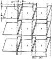
图38是示出了在专利文献2中所公开的三维显示设备的像素的示意性说明。图38(A)是示出了在专利文献2中所公开的三维显示设备的像素布置的平面图,而图38(B)是其像素的放大视图。在专利文献2所公开的三维显示设备,水平相邻像素的总垂直尺寸在交叠区域中沿水平方向的任意位置处都是恒定的。总尺寸等于矩形区域B的垂直尺寸。因此,提供了水平连续且实质上均匀的亮度,并且各处保持了实质上恒定的亮度。FIG. 38 is a schematic illustration showing pixels of the three-dimensional display device disclosed in
因此,当将相同的图像输出到相邻列的像素时,即使观察者的眼睛与孔径之间的边界相交,也保持了恒定的亮度。Therefore, when the same image is output to adjacent columns of pixels, constant brightness is maintained even when the observer's eyes intersect the boundary between the apertures.
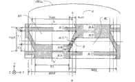
为了更加易于理解,随后将参考附图描述典型的现有技术像素结构。图36是示意性地示出了专利文献1和2中所公开的现有技术像素结构的说明。For easier understanding, a typical prior art pixel structure will be described later with reference to the accompanying drawings. FIG. 36 is an illustration schematically showing a prior art pixel structure disclosed in
为了简化说明,示出了由一对右眼像素4R和左眼像素4L组成的显示单元4。每一个像素的孔径具有等腰梯形形状。当焦点位于组成显示单元4的最小单位像素之一(右眼像素4R或左眼像素4L)上时,其称作不具有具体区分的“子像素”。For simplicity of explanation, the
显示单元4包括至少右眼像素4R和左眼像素4L,作为沿X轴方向彼此相邻的两个子像素。三维图像显示设备包括柱面透镜1003a作为光学分离装置,用于将从子像素的孔径出现的光沿X轴方向分离成分离的图像。The
这里,将图像分离方向定义为X轴方向,将与其垂直的方向定义为Y轴方向。另外,术语“垂直孔径”指的是沿与图像分离方向垂直的方向的孔径宽度(与图37情况下的Y轴相对应)。对于子像素孔径的梯形底部,将较小的底部称作上底,将较大的底部称作下底。Here, the image separation direction is defined as the X-axis direction, and the direction perpendicular thereto is defined as the Y-axis direction. In addition, the term "vertical aperture" refers to the aperture width in the direction perpendicular to the image separation direction (corresponding to the Y axis in the case of FIG. 37 ). For the trapezoidal bottom of the sub-pixel aperture, the smaller bottom is called the upper bottom, and the larger bottom is called the lower bottom.
将右眼像素4R的孔径和左眼像素4L的孔径设置为沿X轴方向彼此紧邻。存在这些孔径边界上沿Y轴方向彼此交叠的区域。将这些孔径彼此交叠的区域称作“交叠区域”,并且这样的区域沿X轴方向的宽度定义为交叠区域宽度Xct1。另一方面,孔径中心处右眼像素4R的孔径和左眼像素4L的孔径彼此不交叠的区域称作“非交叠区域”,并且将这这样区域沿X轴方向的宽度定义为非交叠区域宽度X1。子像素沿X轴方向的间距Xdot等于交叠区域宽度Xct1和非交叠区域宽度X1的总和。The aperture of the right-
子像素的孔径是等腰梯形的形状,所述等腰梯形关于与Y轴平行并且穿过子像素的中心的b-b’线对称,并且具有与X轴平行的上底和下底。将具有有限宽度W的屏蔽线设置在梯形的斜边上。斜边形成相对于Y轴的角度θ。将屏蔽线称作“斜线”。The aperture of the sub-pixel is in the shape of an isosceles trapezoid symmetrical about the b-b' line parallel to the Y-axis and passing through the center of the sub-pixel, and having upper and lower bases parallel to the X-axis. A shielded wire having a finite width W is placed on the hypotenuse of the trapezoid. The hypotenuse forms an angle θ with respect to the Y axis. The shielded wire is called a "slash".
点A和A’是子像素的梯形孔径的下底的顶点。点B和B’是子像素的梯形孔径的上底的顶点。点A和A’以及点B和B’是子像素的垂直孔径宽度开始沿X轴方向改变的拐点。点C是与Y轴平行并且穿过点B的线和梯形孔径的下底相交位置的点,点C’相对于点B’也是如此。Points A and A' are the vertices of the lower base of the sub-pixel's trapezoidal aperture. Points B and B' are the vertices of the upper base of the trapezoidal aperture of the sub-pixel. Points A and A' and points B and B' are inflection points at which the vertical aperture width of the sub-pixel starts to change in the X-axis direction. Point C is the point where the line parallel to the Y axis and passing through point B intersects the lower base of the trapezoidal aperture, as does point C' with respect to point B'.
连接点A和B的线以及连接点A’和B的线彼此平行。那么,交叠区域中右眼像素4R和左眼像素4L的垂直孔径宽度之和沿X轴方向总是恒定的。另外,点A和B’以及点A’和B分别位于与Y轴平行的相同线上,使得非交叠区域中的垂直孔径宽度和交叠区域中右眼像素4R和左眼像素4L的孔径的垂直孔径宽度之和相等。按照这种方式,垂直孔径宽度从交叠区域到非交叠区域是恒定的,并且贯穿沿X轴方向的子像素总是恒定的。The line connecting points A and B and the line connecting points A' and B are parallel to each other. Then, the sum of the vertical aperture widths of the right-
显示单元4具有斜金属线(wire),所述斜金属线相对于Y轴形成角度θ,并且具有显示金属线宽度W。斜金属线的两侧在点A和A’处与梯形孔径的下底相连,在点B和B’处与梯形孔径的上底相连。所述斜金属线在梯形上底处与屏蔽部分相连。这种屏蔽部分沿Y轴方向具有宽度Y2,并且提供其中形成例如用于操作子像素的晶体管或电容器的区域。The
相邻子像素的垂直孔径宽度之和沿X轴方向是恒定的。因此,假设从交叠区域中的孔径区域和非交叠区域的孔径区域中发射亮度相等的光,亮度在与X轴平行的观察位置处保持恒定。那么就不存在亮度角波动,换句话说,3D云纹对于观察者不可见。The sum of vertical aperture widths of adjacent sub-pixels is constant along the X-axis direction. Therefore, assuming that light with equal luminance is emitted from the aperture area in the overlapping area and the aperture area in the non-overlapping area, the luminance remains constant at the observation position parallel to the X-axis. Then there are no angular fluctuations in brightness, in other words, the 3D moiré is invisible to the observer.
这里,通过连接显示单元4的点A、B和C形成的三角形区域和通过连接显示单元4的点A’、B’和C’形成的三角形区域是直角三角形,并且位于交叠区域宽度Xct1之内。这是其中从右眼像素4R和左眼像素4L发射的光彼此交叠的串扰区域。现有技术的像素结构必须至少形成这样的串扰区域,以具有沿X轴方向恒定的垂直孔径宽度,从而引起三维显示器上的3D串扰(一定比率的右眼或左眼图像泄露到另一个图像中)。Here, the triangular area formed by connecting the points A, B, and C of the
这里将详细描述“3D云纹”或“3D串扰”。在该说明书中,由沿不同角度方向显示不同的图像引起的周期性出现的不均匀亮度(有时称作不均匀颜色),具体地亮度角波动定义为“3D云纹”。另一方面,将泄露到另一个图像中的一定比率的右眼或左眼图像定义为“3D串扰”。Here, "3D moiré" or "3D crosstalk" will be described in detail. In this specification, periodically occurring uneven brightness (sometimes referred to as uneven color) caused by displaying different images in different angular directions, specifically brightness angle fluctuations, is defined as "3D moiré". On the other hand, a certain ratio of the right-eye or left-eye image leaking into another image is defined as "3D crosstalk".
通常,将周期性不同的结构彼此干扰时出现的条纹称作“云纹条纹”。云纹条纹是根据结构的周期性或间距而出现的干涉条纹。3D云纹是由图像分离装置的图像形成特性而引起的不均匀亮度。因此,在本说明书中对3D云纹和云纹条纹进行了区分。In general, fringes that appear when structures with different periodicities interfere with each other are called "moiré fringes". Moiré fringes are interference fringes that appear according to the periodicity or spacing of structures. 3D moiré is uneven brightness caused by the image forming characteristics of the image separation device. Therefore, a distinction is made between 3D moiré and moiré fringes in this specification.
3D云纹在一些观察位置可能不是什么问题。然而,较大的亮度角波动估计可能会对于三维观察有不利的影响。因此,希望亮度波动的幅度等于或小于给定的值。3D moiré may not be a problem at some viewing positions. However, larger luminance angle fluctuation estimates may have adverse effects on 3D viewing. Therefore, it is desirable that the magnitude of luminance fluctuation is equal to or smaller than a given value.
另一方面,较大幅度的3D串扰可能会减小三维效果,并且向观察者给出诸如眼睛疲劳之类的不利效果。因此,希望串扰的幅度等于或者小于给定的值。On the other hand, a larger magnitude of 3D crosstalk may reduce the three-dimensional effect and give the observer adverse effects such as eyestrain. Therefore, it is desirable that the magnitude of the crosstalk be equal to or smaller than a given value.
在本说明书中,相对于图36所示的像素形状,将孔径比AP、3D串扰3Dct和3D云纹3Dmoire定义如下。根据所示像素,可以根据屏蔽部分和孔径之间的面积比,通过以下公式来定义孔径比AP。In this specification, with respect to the pixel shape shown in FIG. 36 , the aperture ratio AP, 3D crosstalk 3Dct, and 3D moiré 3Dmoire are defined as follows. According to the pixels shown, the aperture ratio AP can be defined by the following formula according to the area ratio between the shielding portion and the aperture.
[数学公式1][mathematical formula 1]
Ap=Y1/(Y1+Y2+Y3)=(Ydot-Y3-Y2)/YdotAp=Y1/(Y1+Y2+Y3)=(Ydot-Y3-Y2)/Ydot
另外,假设3D串扰对于如同子像素间距Xdot那样大的区域有贡献,可以根据孔径区域和交叠区域之间的面积比,通过以下公式来定义3D串扰(3Dcd)。In addition, assuming that 3D crosstalk contributes to an area as large as the subpixel pitch Xdot, 3D crosstalk (3Dcd) can be defined by the following formula according to the area ratio between the aperture area and the overlapping area.
[数学公式2][Mathematical formula 2]
3Dct=(Xct1×Y1)/(X1×Y1+Xct1×Y1)=Xct1/(X1+Xct1)=Xet1/Xdot3Dct=(Xct1×Y1)/(X1×Y1+Xct1×Y1)=Xct1/(X1+Xct1)=Xet1/Xdot
另外,可以根据非交叠区域中的垂直孔径宽度Y1和交叠区域中右眼和左眼像素4R和4L的垂直孔径宽度之和之间的比率,通过以下公式来定义3D云纹(3Dmoire)。In addition, 3D moiré (3D moire) can be defined by the following formula according to the ratio between the vertical aperture width Y1 in the non-overlapping area and the sum of the vertical aperture widths of the right-eye and left-
[数学公式3][mathematical formula 3]
3Dmoire=1-(Y1+Y2-Wy)/Y1=(W/sinθ-Y2)/Y13Dmoire=1-(Y1+Y2-Wy)/Y1=(W/sinθ-Y2)/Y1
另外,为了保持垂直孔径宽度沿X轴方向恒定,必须建立以下关系:Additionally, in order to keep the vertical aperture width constant along the X-axis, the following relationship must be established:
[数学公式4][mathematical formula 4]
Y2=W/sinθY2=W/sinθ
因此,根据数学公式3和4可以理解的是现有技术的像素理想地具有3Dmoire=0,并且不存在亮度角波动,从而3D云纹几乎不可见。Therefore, it can be understood from
然而,根据数学公式3可以理解的是通过斜金属线的倾角θ确定了交叠区域宽度Xct1,并且当角度θ增加时3D串扰(3Dct)变明显。However, it can be understood from
此外,为了根据数学公式1和4获得所需的孔径比,应该一定程度地增加倾角θ。为此原因,不能够消除3D串扰。即使调节用于分离图像的光学条件,使得3D串扰对于区域的贡献不大于子像素间距Xdot,也不能够消除3D串扰。换句话说,图36所示的现有技术像素具有包括低“3D波纹”和高“3D串扰”的结构。Furthermore, in order to obtain the desired aperture ratio according to
附带地,要求显示设备的显示面板具有更小的像素间距以便改善精细度,并且要求具有更高的所谓孔径比以便改善显示亮度,所述孔径比由孔径和屏蔽部分之间的面积比来确定,并且对显示亮度有贡献。这也可以应用于三维显示设备。Incidentally, the display panel of the display device is required to have a smaller pixel pitch in order to improve fineness, and a higher so-called aperture ratio determined by the area ratio between the aperture and the shielding portion in order to improve display brightness , and contribute to the display brightness. This also applies to three-dimensional display devices.
然而对于更精细的图像,因为必须在屏幕区域中排列更多的像素,必须使得一个像素更小,屏幕区域从最初开始是小的。换句话说,可以将像素尺寸减小多少是个问题。However, for finer images, since more pixels must be arranged in a screen area, one pixel must be made smaller, and the screen area is small from the beginning. In other words, how much you can reduce the pixel size is a question.
随着半导体显微工艺技术的进步,已经实现了更小的像素。然而,诸如开关元件和驱动调制光的液晶的辅助电容器之类的电路不会总是与更精细像素成比例的减小尺寸。这是因为使用显微工艺技术在半导体或玻璃衬底上创建开关元件和辅助电容器,半导体工艺的限制对可实现的精细线宽度强加了上限。即使精细处理在技术上是可用的,设备上的探索至少在目前是昂贵的。With advances in semiconductor micro-processing technology, smaller pixels have been realized. However, circuits such as switching elements and auxiliary capacitors that drive liquid crystals that modulate light are not always downsized in proportion to finer pixels. This is because the switching elements and auxiliary capacitors are created on semiconductor or glass substrates using micro-processing techniques, and the limitations of the semiconductor process impose an upper limit on the achievable fine line width. Even if fine processing is technically available, on-device exploration is at least currently expensive.
另外,由于伴随更高精细度的限制,液晶显示设备经过屏蔽区域的增加,即孔径比的减小,产生了显示设备总体上低效率地使用光的问题。换句话说,通过更精细的像素改善图像质量导致更低的光利用效率。因此,利用液晶显示设备实现更精细的图像并且实现高质量和高效率图像显示设备成为了一个问题。In addition, due to the increase of the shielded area of the liquid crystal display device accompanying the limitation of higher fineness, that is, the decrease of the aperture ratio, there arises a problem that the display device uses light inefficiently as a whole. In other words, improving image quality through finer pixels results in lower light utilization efficiency. Therefore, realizing a finer image using a liquid crystal display device and realizing a high-quality and high-efficiency image display device has become a problem.
具有如同在专利文献1和2中所公开的三维图像显示设备所述的两个或更多观察点的三维显示面板具有与一个像素中的观察点个数相对应的多个子像素。因此,在一个像素中的金属线和开关元件中所涉及的面积增加。具体地,更精细的像素具有显著减小的孔径比,因此孔径比的改善是个重要的问题。A three-dimensional display panel having two or more observation points as described in the three-dimensional image display devices disclosed in
由于上述原因,必须将更精细的像素设计为至少在孔径比方面具有优势以便确保所需的透射率。为了增加孔径面积,必须增加边界区域中的金属线角度θ。然而,如果增加金属线角度θ,也增加了交叠区域宽度Xct1,从而3D串扰变得明显,使得会不利地影响三维显示的可见度。具体地,如专利文献1中所公开的,当根据观察点的个数沿垂直方向划分正方形像素、并且以水平条形图案提供滤色器时,根据颜色的个数子像素沿Y轴方向变得非常小。当子像素沿Y轴方向变小时,因为斜金属线具有有限的宽度,即使增加倾角θ,也不能保持沿X轴方向的垂直孔径宽度恒定。换句话说,难以实现同时确保3D串扰和孔径比、并且具有用于减小3D云纹的近似恒定的垂直孔径比的精细像素结构。For the above reasons, finer pixels must be designed to be advantageous at least in terms of aperture ratio in order to ensure the required transmittance. In order to increase the aperture area, the wire angle θ in the boundary region must be increased. However, if the wire angle θ is increased, the overlapping region width Xct1 is also increased, so that 3D crosstalk becomes conspicuous, so that the visibility of the three-dimensional display is adversely affected. Specifically, as disclosed in
另一方面,在使用双凸透镜来分离图像的三维显示系统中,应该减小光斑直径以改善透镜的分离性能,以便增加舒服地观察三维图像的区域。近来,先进的透镜处理技术允许具有几微米量级光斑直径的透镜的应用。然而,当减小光斑直径时,即使在如图36所示的现有技术中设计为沿图像分离方向具有近似恒定的垂直孔径宽度的像素结构中,也增加了由于生产工艺的工艺精度而导致的微小几何变化。因此,局部出现不均匀的亮度,显著地劣化了图像质量。On the other hand, in a three-dimensional display system using a lenticular lens to separate images, the spot diameter should be reduced to improve the separation performance of the lens in order to increase the area where the three-dimensional image can be comfortably observed. Recently, advanced lens processing techniques have allowed the application of lenses with spot diameters on the order of several micrometers. However, when the spot diameter is reduced, even in a pixel structure designed to have an approximately constant vertical aperture width along the image separation direction in the prior art as shown in FIG. small geometric changes. Therefore, uneven luminance locally occurs, significantly deteriorating image quality.
在上述解释中,子像素具有等腰梯形的孔径。明显的是在专利文献2中公开的近似平行四边形像素结构具有相同的问题。In the above explanation, the sub-pixel has an aperture of an isosceles trapezoid. It is apparent that the approximately parallelogram pixel structure disclosed in
考虑到上述情况而发明了本发明,并且本发明的示例目的是提供一种具有减小的3D串扰和改进的孔径比的图像显示设备,同时最小化3D云纹的影响,以便改善三维显示质量。The present invention was invented in consideration of the above circumstances, and an exemplary object of the present invention is to provide an image display device having reduced 3D crosstalk and improved aperture ratio while minimizing the influence of 3D moiré so as to improve three-dimensional display quality .
发明内容Contents of the invention
为了实现上述目的,根据本发明第一示例方面的图像显示设备包括:In order to achieve the above objects, an image display device according to a first exemplary aspect of the present invention includes:
显示面板,具有多个显示单元,所述显示单元排列成矩阵,并且至少包括显示第一观察点图像的像素和显示第二观察点图像的像素;以及a display panel having a plurality of display units arranged in a matrix and including at least pixels displaying a first viewpoint image and pixels displaying a second viewpoint image; and
光学装置,用于沿彼此不同的方向对从显示第一观察点图像的像素和显示第二观察点图像的像素发射的光进行分类,其中optical means for sorting light emitted from the pixels displaying the image of the first viewpoint and the pixels displaying the image of the second viewpoint in directions different from each other, wherein
显示第一观察点图像的像素和显示第二观察点图像的像素沿第一方向彼此相邻;The pixels displaying the image of the first viewpoint and the pixels displaying the image of the second viewpoint are adjacent to each other along the first direction;
所述显示单元按照沿第一方向延伸的行和沿与第一方向垂直的第二方向延伸的列排列;The display units are arranged in rows extending along a first direction and columns extending along a second direction perpendicular to the first direction;
在显示第一观察点图像的像素的孔径和显示第二观察点图像的像素的孔径周围提供屏蔽部分;providing a shielding portion around the aperture of the pixel displaying the image of the first viewpoint and the aperture of the pixel displaying the image of the second viewpoint;
显示第一观察点图像的像素的孔径和显示第二观察点图像的像素的孔径由第一区域和第二区域组成,在第一区域中所述孔径沿第二方向彼此交叠,第二区域是不同于第一区域的区域;An aperture of a pixel displaying an image of a first viewpoint and an aperture of a pixel displaying an image of a second viewpoint are composed of a first area and a second area, in which the apertures overlap each other in a second direction, and in the second area is a region different from the first region;
在第一区域内显示第一观察点图像的像素的孔径和显示第二观察点图像的像素的孔径沿第二方向的总孔径宽度构成了第一孔径宽度;The total aperture width of the apertures of the pixels displaying the first viewpoint image and the apertures of the pixels displaying the second viewpoint image in the first area along the second direction constitutes a first aperture width;
在第二区域内显示第一观察点图像的像素的孔径和显示第二观察点图像的像素的孔径沿第二方向的孔径宽度构成了第二孔径宽度;The aperture width of the aperture of the pixel displaying the first viewpoint image and the aperture of the pixel displaying the second viewpoint image in the second area along the second direction constitutes a second aperture width;
假设从第一区域与第二区域之间的边界附近到第一区域中心的方向是第一方向的正方向,那么第一孔径宽度相对于第一方向的导数是非零实数;以及Assuming that the direction from near the boundary between the first region and the second region to the center of the first region is the positive direction of the first direction, then the derivative of the first aperture width with respect to the first direction is a non-zero real number; and
对于第一区域内屏蔽部分与显示第一观察点图像的像素的孔径之间的边界线以及屏蔽部分与显示第二观察点图像的像素的孔径之间的边界线,与第二方向相交叉的边界线包括至少一个或多个拐点。For the boundary line between the shielded part and the aperture of the pixel displaying the first viewpoint image in the first area and the boundary line between the shielding part and the aperture of the pixel displaying the second viewpoint image, the direction intersecting the second direction The boundary line includes at least one or more inflection points.
根据本发明另一个示例方面的图像显示设备包括:An image display device according to another exemplary aspect of the present invention includes:
显示面板,具有多个显示单元,所述显示单元排列成矩阵,并且至少包括显示N个观察点图像的N个像素(N是等于或大于2的整数),所述N个像素按照从第一观察点到第N观察点的顺序排列;以及A display panel having a plurality of display units arranged in a matrix and including at least N pixels (N is an integer equal to or greater than 2) displaying N viewpoint images, the N pixels according to the order from the first The sequential arrangement of the observation point to the Nth observation point; and
光学装置,用于沿彼此不同的方向对从显示N个观察点图像的N个像素发射的光进行分类,其中optical means for sorting light emitted from N pixels displaying N viewpoint images in directions different from each other, wherein
显示第k个(k是1,...,N-1的整数)观察点图像的像素和显示第k+1个观察点图像的像素沿第一方向彼此相邻;The pixels displaying the kth (k is an integer of 1, ..., N-1) viewpoint image and the pixels displaying the k+1th viewpoint image are adjacent to each other along the first direction;
所述显示单元按照沿第一方向延伸的行和沿与第一方向垂直的第二方向延伸的列排列;The display units are arranged in rows extending along a first direction and columns extending along a second direction perpendicular to the first direction;
在显示N个观察点图像的N个像素的孔径周围提供屏蔽部分;providing a shielding portion around an aperture of N pixels displaying images of N viewpoints;
显示第k个观察点图像的像素的孔径和显示第k+1个观察点图像的像素的孔径由第一区域和第二区域组成,在第一区域中所述孔径沿第二方向彼此交叠,第二区域是不同于第一区域的区域;The aperture of the pixel displaying the k-th viewpoint image and the aperture of the pixel displaying the k+1-th viewpoint image consist of a first area and a second area in which the apertures overlap each other in the second direction , the second area is an area different from the first area;
在第一区域内显示第k个观察点图像的像素的孔径和显示第k+1个观察点图像的像素的孔径沿第二方向的总孔径宽度构成了第一孔径宽度;The total aperture width of the aperture of the pixel displaying the kth observation point image in the first area and the aperture of the pixel displaying the k+1 observation point image along the second direction constitutes the first aperture width;
在第二区域内显示第k个观察点图像的像素的孔径和显示第k+1个观察点图像的像素的孔径沿第二方向的孔径宽度构成了第二孔径宽度;In the second area, the aperture of the pixel displaying the kth observation point image and the aperture width of the pixel displaying the k+1 observation point image along the second direction constitute the second aperture width;
假设从第一区域与第二区域之间的边界附近到第一区域中心的方向是第一方向的正方向,那么第一孔径宽度相对于第一方向的导数是非零实数;Assuming that the direction from the vicinity of the boundary between the first region and the second region to the center of the first region is the positive direction of the first direction, then the derivative of the first aperture width with respect to the first direction is a non-zero real number;
对于第一区域内屏蔽部分与显示第k个观察点图像的像素的孔径之间的边界线以及屏蔽部分与显示第k+1个观察点图像的像素的孔径之间的边界线,与第二方向相交叉的边界线包括至少一个或多个拐点;For the boundary line between the shielding part and the aperture of the pixel displaying the k-th observation point image in the first area and the boundary line between the shielding part and the aperture of the pixel displaying the k+1 observation point image, the same as the second The boundary lines whose directions intersect include at least one or more inflection points;
近似平行于第一方向的屏蔽部分与边界线之间的一个交叉点位于不包括第一区域与第二区域之间边界的第一区域中;以及a point of intersection between the shielding portion approximately parallel to the first direction and the boundary line is located in the first area excluding the boundary between the first area and the second area; and
第一孔径宽度小于第二孔径宽度。The first aperture width is smaller than the second aperture width.
根据本发明另一示例方面的图像显示设备包括:An image display device according to another exemplary aspect of the present invention includes:
显示面板,具有多个显示单元,所述显示单元排列成矩阵,并且至少包括显示N个观察点图像的N个像素(N是等于或大于2的整数);以及a display panel having a plurality of display units arranged in a matrix and including at least N pixels displaying N viewpoint images (N is an integer equal to or greater than 2); and
光学装置,用于沿彼此不同的方向对从显示N个观察点图像的N个像素发射的光进行分类,其中:optical means for sorting light emitted from N pixels displaying N viewpoint images in directions different from each other, wherein:
显示N个观察点图像的N个像素按照沿第一方向延伸的N行和沿与第一方向垂直的第二方向延伸的N列的矩阵排列;N pixels displaying N viewpoint images are arranged in a matrix of N rows extending along the first direction and N columns extending along the second direction perpendicular to the first direction;
在显示N个观察点图像的N个像素的孔径周围提供屏蔽部分;providing a shielding portion around an aperture of N pixels displaying images of N viewpoints;
沿第一方向显示第k个(k是1,...,N-1的整数)观察点图像的像素的孔径和显示第k+1个观察点图像的像素的孔径由第一区域和第二区域组成,在第一区域中所述孔径沿第二方向彼此交叠,第二区域是不同于除了第一区域的区域;The aperture of the pixel displaying the kth (k is an integer of 1, ..., N-1) observation point image along the first direction and the aperture of the pixel displaying the k+1 observation point image are determined by the first region and the first region consisting of two regions in which the apertures overlap each other along a second direction, the second region being a region different from the first region;
沿第二方向显示第i个(i是1,...,N-1的整数)观察点图像的像素的孔径和显示第i+1个观察点图像的像素的孔径由第三区域和第四区域组成,在第三区域中所述孔径沿第一方向彼此交叠,第四区域是不同于第三区域的区域;Along the second direction, the i-th (i is an integer of 1, . Composed of four regions, in the third region the apertures overlap each other along the first direction, and the fourth region is a region different from the third region;
在第一区域内显示第k个观察点图像的像素的孔径和显示第k+1个观察点图像的像素的孔径沿第二方向的总孔径宽度构成了第一孔径宽度;The total aperture width of the aperture of the pixel displaying the kth observation point image in the first area and the aperture of the pixel displaying the k+1 observation point image along the second direction constitutes the first aperture width;
在第二区域内显示第k个观察点图像的像素的孔径和显示第k+1个观察点图像的像素的孔径沿第二方向的孔径宽度构成了第二孔径宽度;In the second area, the aperture of the pixel displaying the kth observation point image and the aperture width of the pixel displaying the k+1 observation point image along the second direction constitute the second aperture width;
假设从第一区域与第二区域之间的边界附近到第一区域中心的方向是第一方向的正方向,那么第一孔径宽度相对于第一方向的导数是非零实数;Assuming that the direction from the vicinity of the boundary between the first region and the second region to the center of the first region is the positive direction of the first direction, then the derivative of the first aperture width with respect to the first direction is a non-zero real number;
对于第一区域内屏蔽部分与显示第k个观察点图像的像素的孔径之间的边界线以及屏蔽部分与显示第k+1个观察点图像的像素的孔径之间的边界线,与第二方向相交叉的边界线包括至少一个或多个拐点;For the boundary line between the shielding part and the aperture of the pixel displaying the k-th observation point image in the first area and the boundary line between the shielding part and the aperture of the pixel displaying the k+1 observation point image, the same as the second The boundary lines whose directions intersect include at least one or more inflection points;
近似平行于第一方向的屏蔽部分与边界线之间的一个交叉点位于不包括第一区域与第二区域之间边界的第一区域中;a point of intersection between the shielding portion approximately parallel to the first direction and the boundary line is located in the first area excluding the boundary between the first area and the second area;
第一孔径宽度小于第二孔径宽度;the first aperture width is less than the second aperture width;
第三区域内显示第i个观察点图像的像素的孔径和显示第i+1个观察点图像的像素的孔径沿第一方向的总孔径宽度构成了第三孔径宽度;The total aperture width of the aperture of the pixel displaying the i-th observation point image in the third area and the aperture of the pixel displaying the i+1 observation point image along the first direction constitutes the third aperture width;
假设从第三区域与第四区域之间的边界附近到第三区域中心的方向是第二方向的正方向,那么第三孔径宽度相对于第二方向的导数是非零实数;Assuming that the direction from the vicinity of the boundary between the third region and the fourth region to the center of the third region is the positive direction of the second direction, then the derivative of the third aperture width with respect to the second direction is a non-zero real number;
对于第三区域内屏蔽部分与显示第i个观察点图像的像素的孔径之间的边界线以及屏蔽部分与显示第i+1个观察点图像的像素的孔径之间的边界线,与第一方向相交叉的边界线包括至少一个或多个拐点;以及For the boundary line between the shielding part and the aperture of the pixel displaying the i-th observation point image in the third area and the boundary line between the shielding part and the aperture of the pixel displaying the i+1 observation point image, the same as the first Boundary lines whose directions intersect include at least one or more inflection points; and
近似平行于第一方向的屏蔽部分与边界线与之间的一个交叉点位于不包括第三区域与第四区域之间边界的第三区域中。A point of intersection between the shielding portion and the boundary line approximately parallel to the first direction is located in the third area excluding the boundary between the third area and the fourth area.
本发明的示例目的提供了一种图像显示设备和显示面板,具有减小的3D串扰和改进的孔径比,同时尽可能地最小化了3D云纹的影响,以改善三维显示质量。An example object of the present invention is to provide an image display device and a display panel having reduced 3D crosstalk and improved aperture ratio while minimizing the influence of 3D moiré as much as possible to improve three-dimensional display quality.
附图说明Description of drawings
在阅读以下详细描述和附图时,本发明的这些目的和其他目的以及优势将变得更加显而易见,其中:These and other objects and advantages of the present invention will become more apparent upon reading the following detailed description and accompanying drawings, in which:
[图1]示出了根据本发明实施例1的显示面板的像素的平面图;[FIG. 1] A plan view showing a pixel of a display panel according to
[图2]示出了根据本发明实施例1的图像显示设备的截面图;[FIG. 2] A sectional view showing an image display device according to
[图3]示出了根据本发明实施例1的显示面板的像素的放大视图;[FIG. 3] An enlarged view showing pixels of a display panel according to
[图4]示出了根据本发明实施例1的显示面板的垂直孔径宽度分布的图解表示;[FIG. 4] A graphical representation showing the vertical aperture width distribution of the display panel according to
[图5]示出了使用双凸透镜的光学模型的截面图;[ Fig. 5 ] A sectional view showing an optical model using a biconvex lens;
[图6]示出了用于计算双凸透镜图像分离条件最小曲率半径的光学模式的说明;[FIG. 6] An illustration showing an optical model for calculating the minimum curvature radius of the lenticular lens image separation condition;
[图7]示出了用于计算双凸透镜图像分离条件最大曲率半径的光学模式的说明;[FIG. 7] An illustration showing an optical model for calculating the maximum curvature radius of the lenticular lens image separation condition;
[图8]示出了根据本发明实施例1的图像显示设备的行为的截面图;[ Fig. 8 ] A sectional view showing the behavior of the image display device according to
[图9]示出了根据本发明实施例1的图像显示设备中的示例亮度分布的图解表示;[FIG. 9] A diagrammatic representation showing an example luminance distribution in the image display device according to
[图10]示出了从根据本发明实施例1的显示面板的像素发射的光的方向与3D串扰之间关系的示意性说明:[ FIG. 10 ] A schematic illustration showing the relationship between the direction of light emitted from the pixels of the display panel according to
[图11]示出了像素的垂直孔径宽度分布与光斑直径之间关系的图解表示;[FIG. 11] A graphical representation showing the relationship between the vertical aperture width distribution of a pixel and the spot diameter;
[图12]示出了在根据本发明实施例1的显示面板的像素中沿X轴方向的亮度分布与光斑直径SP之间关系的图解表示(A),以及示出了其一部分的图解表示(B);[FIG. 12] A graphical representation (A) showing the relationship between the luminance distribution in the X-axis direction and the spot diameter SP in the pixel of the display panel according to
[图13]示出了在根据本发明实施例1的显示面板的像素中的垂直孔径宽度分布(A)和亮度分布(B)的示意图;[FIG. 13] A schematic diagram showing a vertical aperture width distribution (A) and a luminance distribution (B) in a pixel of a display panel according to
[图14]示出了在根据本发明实施例1的显示面板的像素中的光斑直径SP与3D云纹之间关系的图解表示;[FIG. 14] A graphical representation showing the relationship between the spot diameter SP and 3D moiré in the pixel of the display panel according to
[图15]示出了在根据本发明实施例1的显示面板的像素中光斑直径SP与亮度变化的梯度ΔY/ΔX之间关系的图解表示;[FIG. 15] A graphical representation showing the relationship between the spot diameter SP and the gradient ΔY/ΔX of the luminance change in the pixel of the display panel according to
[图16]示出了在根据本发明实施例1的显示面板的像素中光斑直径SP与三维观察范围之间关系的图解表示;[FIG. 16] A graphical representation showing the relationship between the spot diameter SP and the three-dimensional observation range in the pixel of the display panel according to
[图17]示出了根据本实施例的图像显示设备的光收集的概念性说明;[FIG. 17] A conceptual illustration showing light collection of the image display device according to the present embodiment;
[图18]示出了特殊系统的概念性说明;[FIG. 18] shows a conceptual illustration of a special system;
[图19]示出了根据本发明实施例1的修改实施例1的显示面板的像素的平面图;[FIG. 19] A plan view showing a pixel of a display panel according to
[图20]示出了根据本发明实施例1的修改实施例2的显示面板的像素的平面图;[FIG. 20] A plan view showing a pixel of a display panel according to
[图21]示出了根据本发明实施例2的显示面板的像素的平面图;[FIG. 21] A plan view showing a pixel of a display panel according to
[图22]示出了根据本发明实施例3的显示面板的像素的平面图;[FIG. 22] A plan view showing a pixel of a display panel according to
[图23]示出了在用于比较的实施例中沿X轴方向的位置和垂直孔径宽度分布的图解表示;[FIG. 23] A diagrammatic representation showing the position along the X-axis direction and the vertical aperture width distribution in Examples for comparison;
[图24]示出了在用于比较的实施例中沿X轴方向的位置及其导数的图解表示;[ Fig. 24 ] shows a graphical representation of the position along the X-axis direction and its derivative in the embodiment for comparison;
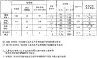
[图25]示出了实施例的评估结果的表;[ Fig. 25 ] A table showing evaluation results of Examples;
[图26]示出了根据本发明实施例3的修改实施例1的显示面板的像素的平面图;[FIG. 26] A plan view showing a pixel of a display panel according to
[图27]示出了在根据本发明实施例3的修改实施例1的显示面板的像素中的垂直孔径宽度分布(A)和亮度分布(B)的示意图;[FIG. 27] A schematic diagram showing a vertical aperture width distribution (A) and a luminance distribution (B) in pixels of a display panel according to Modification Example 1 of
[图28]示出了根据本发明实施例4的显示面板的像素的平面图;[FIG. 28] A plan view showing a pixel of a display panel according to
[图29]示出了根据本发明实施例5的显示面板的像素的平面图;[FIG. 29] A plan view showing a pixel of a display panel according to Embodiment 5 of the present invention;
[图30]示出了从根据本发明实施例5的显示面板的像素发射的光的方向与3D串扰之间的关系的示意性说明;[FIG. 30] A schematic illustration showing the relationship between the direction of light emitted from a pixel of a display panel according to Embodiment 5 of the present invention and 3D crosstalk;
[图31]示出了根据本发明实施例6的显示面板的像素的平面图;[FIG. 31] A plan view showing a pixel of a display panel according to
[图32]示出了根据本发明实施例7的显示面板的像素的平面图;[FIG. 32] A plan view showing a pixel of a display panel according to Embodiment 7 of the present invention;
[图33]示出了可应用于根据本发明实施例8的图像显示设备的蝇眼透镜的透视图;[FIG. 33] A perspective view showing a fly's-eye lens applicable to an image display device according to
[图34]示出了根据本发明实施例8的显示面板的像素的平面图;[FIG. 34] A plan view showing a pixel of a display panel according to
[图35]示出了安装了本发明的图像显示设备的便携设备的透视图;[FIG. 35] A perspective view showing a portable device in which the image display device of the present invention is mounted;
[图36]示出了现有技术三维图像显示设备的像素的平面图;[FIG. 36] A plan view showing pixels of a prior art three-dimensional image display device;
[图37]示出了现有技术三维图像显示设备的像素的平面图;以及[FIG. 37] A plan view showing pixels of a prior art three-dimensional image display device; and
[图38]示出了现有技术三维图像显示设备的像素的平面图。[ Fig. 38 ] A plan view showing pixels of a related art three-dimensional image display device.
具体实施方式Detailed ways
下文中将参考附图描述根据本发明实施例的显示面板和图像显示设备。在附图中,剖开了一些部分以区分诸如屏蔽部分之类的元件,而不是为了表示横截面。Hereinafter, a display panel and an image display device according to embodiments of the present invention will be described with reference to the accompanying drawings. In the drawings, some parts are cut away to distinguish elements such as shielding parts, not to show cross-sections.
[实施例1][Example 1]
将参考附图描述根据该实施例的图像显示设备和显示面板。An image display device and a display panel according to this embodiment will be described with reference to the drawings.
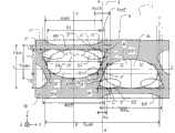
图1是示出了根据该实施例的显示面板的像素的平面图。FIG. 1 is a plan view showing pixels of a display panel according to this embodiment.
显示面板2是两个观察点的三维显示面板,包括显示第一观察点图像的像素和显示第二观察点图像的像素。在该实施例中,第一观察点像素是左眼像素4L,而第二观察点像素是右眼像素4R。The
一对左眼像素4L和右眼像素4R组成显示单元4。当焦点位于构成显示单元4的最小单位像素之一上时(左眼像素4L或右眼像素4R),将其称作“子像素”。子像素排列成矩阵。A pair of left-
柱面透镜3a是具有圆形凸起部分的一维透镜。柱面透镜3a沿与显示平面内的阵列方向垂直的方向延伸或伸长。柱面透镜3a沿所述延伸方向没有透镜效果,所述柱面透镜3a只沿与其垂直的阵列方向具有透镜效果。The
图2是示出了根据本发明的图像显示设备的截面图。FIG. 2 is a cross-sectional view showing an image display device according to the present invention.
图像显示设备1包括:使用液晶分子作为电光元件的显示面板2、双凸透镜3和背光15。双凸透镜3是由沿一个维度排列的许多柱面透镜3a组成的透镜阵列。柱面透镜3a只沿阵列方向具有透镜效果。柱面透镜3a的阵列方向等于左眼像素4L和右眼像素4R交替排列的方向。柱面透镜3a根据显示单元4来定位。The
透镜效果的上述方向等于左眼像素4L和右眼像素4R交替排列的方向。因此,柱面透镜3a用作将左眼像素4L和右眼像素4R的光分离到不同方向的光束分离装置。然后,柱面透镜3a可以沿不同的方向分离由左眼像素4L显示的图像和由右眼像素4R显示的图像。换句话说,双凸透镜3是用作图像分离装置或图像分类装置的光学元件。这里,柱面透镜3a具有位于柱面透镜3a的原点或顶点与左眼像素4L或右眼像素4R的像素表面或平面的点。The above-mentioned direction of the lens effect is equal to the direction in which the left-
在本说明书中,为了方便起见将XYX笛卡尔坐标系统定义如下。在左眼像素4L和右眼像素4R交替排列的方向中,将从右眼像素4R到左眼像素4L的第一方向定义为+X方向,将相反的方向定义为-X方向。+X方向和-X方向统称为X轴方向。柱面透镜3a的长度方向是第二方向,并且将其定义为Y轴方向。另外,将与X轴方向和Y轴方向都垂直的第三方向定义为Z轴方向。对于Z轴方向,将从左眼像素4L或右眼像素4R的平面到双凸透镜3的方向定义为+Z方向,并且将相反的方向定义为-Z方向。+Z方向朝前或者朝着观察者延伸。观察者观察沿+Z方向的侧面上的显示面板2。另外,+Y方向是建立右手坐标系统的方向。换句话说,当人右手的拇指指向+X方向且食指指向Y方向时,中指指向+Z方向。In this specification, the XYX Cartesian coordinate system is defined as follows for convenience. Among the directions in which the left-
在如上所述的XYZ笛卡尔坐标系中,将柱面透镜3a沿X轴方向排列,并且左眼图像和右眼图像沿X轴方向分离。显示单元4沿Y轴方向排成一行。显示单元4和柱面透镜3a沿X轴方向按照相同的间距排列。另外,柱面透镜3a每一个均按照沿Y轴方向排列的显示单元4的列来定位。In the XYZ Cartesian coordinate system as described above, the
在该实施例中,将沿X轴的像素的线称作行,将沿Y轴的像素的线称作列。In this embodiment, a line of pixels along the X-axis is called a row, and a line of pixels along the Y-axis is called a column.
如图1所示,显示单元4包括右眼像素4R和左眼像素4L,显示单元4’包括右眼像素4R’和左眼像素4L’。As shown in FIG. 1 , the
在该实施例中,一个像素包括三个显示单元。每一个显示单元4颜色为红色、绿色或蓝色。红色、绿色和蓝色滤色器沿X轴方向延伸,并且产生沿Y轴方向重复的条形图案。颜色的顺序不局限于上述顺序,并且可以按照任意顺序组合红色、绿色和蓝色。另外,一个像素可以包括三种或更多显示单元的组合。在这种情况下,颜色不局限于上述颜色,可以使用三种或更多种颜色。In this embodiment, one pixel includes three display units. The color of each
如图2所示,显示单元2在TFT(薄膜晶体管)基底2a与相对基底2b之间的具有较小的间隔,在所述间隔中提供了液晶层5LC。在显示面板2沿-Z方向的一侧上提供TFT基底2a,并且在沿+Z方向的一侧上提供相对的基底2b。在相对基底2b另外沿+Z轴方向的一侧上提供双凸透镜3。将偏振片11应用于TFT基底2a沿+Z方向的一侧上,并且应用于相对基底2b沿-Z方向的一侧上。将图1所示的滤色器和屏蔽部分76提供给相对基底2b。然而,这并非是限制性的。提供给TFT基底2a的屏蔽层也包括在屏蔽部分76中。As shown in FIG. 2, the
将参考图1详细描述根据该实施例的图像显示设备1的像素结构。The pixel structure of the
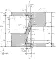
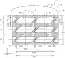
显示面板2的子像素具有由平面视图中的两个梯形的组合构成的六边形孔径。更具体地,通过提供第一梯形和第二梯形来形成所述孔径形状,所述第一梯形关于与Y轴平行并且通过子像素的中心的b-b’线两侧对称,所述第二梯形具有长度等于第一梯形下底的下底,它们的下底彼此接触。在本说明书中,梯形的底中较大的底称作下底,较小的底称作上底。然而,因为一个梯形沿Y轴方向具有较小的高度,可以将所述六边形形状实质上看作是近似梯形形状。在以下说明中,将六边形子像素看作近似梯形像素。另外根据以上描述,底中较大的底称作下底,较小的底称作上底。在近似梯形孔径周围提供屏蔽部分。The sub-pixels of the
换句话说,显示面板2的上述子像素具有近似梯形孔径,其具有近似平行于X轴的上底和下底以及沿与Y轴方向不同的方向倾斜的两条斜边,在近似梯形形状的锐角部分处提供近似三角形屏蔽部分(例如三角形ADE)。In other words, the above-mentioned sub-pixel of the
所述孔径具有关于线b-b’双侧对称的斜边。因此,组成所述孔径的斜边包括彼此沿相对于Y轴方向的相反方向倾斜的一对边,并且相对于Y轴成相同角度延伸。The apertures have hypotenuses that are bilaterally symmetrical about the line b-b'. Accordingly, the hypotenuses constituting the aperture include a pair of sides inclined to each other in opposite directions with respect to the Y-axis direction, and extend at the same angle with respect to the Y-axis.
沿X轴方向彼此相邻的子像素相对于中心O对称。按照以下方式设置右眼像素4R的孔径和左眼像素4L的孔径:使得孔径的中心沿Y轴方向处于不同的水平面。沿Y轴方向彼此相邻的子像素按照以下方式排列:使得它们的上底或下底彼此面对。Sub-pixels adjacent to each other in the X-axis direction are symmetrical with respect to the center O. The aperture of the right-
右眼像素4R的孔径和左眼像素4L的孔径沿Y轴方向彼此交叠。将这一区域称作“交叠区域”,并且将其沿X轴方向的宽度定义为交叠区域宽度Xct2。换句话说,宽度Xct2是沿X轴方向位于最外边的点E和E’之间的孔径区域的宽度。另一方面,将右眼像素4R和左眼像素4L的孔径不交叠的区域称作“不交叠区域”,并且将其沿X轴方向的宽度定义为不交叠区域宽度X1。子像素沿X轴方向的宽度Xdot等于交叠区域宽度Xct2和不交叠区域宽度X1之和。The aperture of the right-
将参考图3进一步详细地描述图像显示设备1的像素结构。图3是根据该实施例的显示面板的像素的放大视图。The pixel structure of the
在梯形斜边处提供具有有限宽度W的屏蔽线。斜边相对于Y轴方向成角度θ。在本说明书中,所述角度沿+Y轴方向为零,并且顺时针方向增加。A shielded wire having a finite width W is provided at the hypotenuse of the trapezoid. The hypotenuse makes an angle θ with respect to the Y-axis direction. In this description, the angle is zero along the +Y axis direction and increases clockwise.
与Y轴平行并且穿过右眼像素4R的孔径的最外面点E的线形成不交叠区域和交叠区域之间的边界线。在近似梯形孔径的下底处,屏蔽部分与孔径之间的边界线与X轴平行。点F是下底处的边界线与平行于Y轴并且穿过点E’的线之间的交叉点,并且是右眼像素4R的斜边与平行于Y轴且穿过点E’的线之间的交叉点。A line parallel to the Y axis and passing through the outermost point E of the aperture of the right-
点A是连接点B和点E的延长线与近似梯形孔径的下底的延长线之间的交叉点,点B是右眼像素4R的近似梯形孔径的上底的顶点。点A’是对于左眼像素4L类似地获得的交叉点。点A和B’位于与Y轴平行的相同线上,点A’和B也是如此。Point A is the intersection point between the extension line connecting points B and E and the extension line of the lower base of the approximate trapezoidal aperture, and point B is the apex of the upper base of the approximate trapezoidal aperture of the right-
点C是连接A’和B的延长线与右眼像素4R的近似梯形孔径的下底之间的交叉点。点C’是对于左眼像素4L类似地获得的交叉点。Point C is the intersection between the extension line connecting A' and B and the lower base of the approximately trapezoidal aperture of the right-
点D位于点A和F之间,并且在交叠区域宽度Xct2之内。Point D is located between points A and F and within the width Xct2 of the overlapping region.
连接点D和E的线和连接点D’和E’的线相对于Y轴方向倾斜,并且与显示单元4的中心线a-a’交叉。The line connecting the points D and E and the line connecting the points D' and E' are inclined with respect to the Y-axis direction, and cross the center line a-a' of the
子像素具有近似梯形孔径;通过由点A、D和E包围的三角形和通过由点A’、D’和E’包围的三角形遮挡了梯形下底处的锐角部分,形成六边形孔径。由点A、B和C包围的直角三角形和由点A’、B’和C’包围的直角三角形沿Y轴方向彼此交叠,形成了沿X轴方向具有交叠宽度Xct的交叠区域。这里,因为通过由点A、D和E包围的三角形和由点A’、D’和E’包围的三角形遮挡了子像素的孔径,交叠区域宽度Xct2小于Xct。The sub-pixel has an approximately trapezoidal aperture; a hexagonal aperture is formed by the triangle enclosed by points A, D, and E and by the triangle enclosed by points A', D', and E' occluding the acute corner at the lower base of the trapezoid. The right triangle surrounded by the points A, B, and C and the right triangle surrounded by the points A', B', and C' overlap each other in the Y-axis direction, forming an overlapping region with an overlapping width Xct in the X-axis direction. Here, since the aperture of the sub-pixel is blocked by the triangle surrounded by the points A, D, and E and the triangle surrounded by the points A', D', and E', the overlapping area width Xct2 is smaller than Xct.
这里,连接点A和C的线段长度L(A-C)和垂直孔径宽度Y1具有关系L(A-C)=Y1xtanθ,并且连接点A’和C’的线段长度L(A’-C’)和垂直孔径宽度Y1也具有类似的关系。换句话说,点A、B和C以及点A’、B’和C’具有与图36中所示像素中的点A、B和C以及点A’、B’和C’相同的位置关系。Here, the line segment length L(A-C) connecting points A and C and the vertical aperture width Y1 have a relationship L(A-C)=Y1xtanθ, and the line segment length L(A'-C') connecting points A' and C' and the vertical aperture width The width Y1 also has a similar relationship. In other words, points A, B, and C, and points A', B', and C' have the same positional relationship as points A, B, and C, and points A', B', and C' in the pixel shown in FIG. 36 .
设置由点A、D和E包围的三角形的面积Sct2,使得存在交叠区域宽度Xct2,并且小于由点A、B和C包围的三角形的面积Sct1。这同样也适用于由点A’、D’和E’包围的三角形的面积Sct2’和由点A’、B’和C’包围的三角形的面积Sct1’。The area Sct2 of the triangle surrounded by the points A, D, and E is set so that there is an overlapping region width Xct2 and is smaller than the area Sct1 of the triangle surrounded by the points A, B, and C. The same applies to the area Sct2' of the triangle enclosed by the points A', D' and E' and the area Sct1' of the triangle enclosed by the points A', B' and C'.
假设在梯形斜边上提供且具有宽度W的斜金属线沿X轴方向具有宽度WX1,WX1=W/cosθ。另外,假设斜金属线沿Y轴方向具有宽度WY1,WY1=W/sinθ。Assuming that an oblique metal line provided on a trapezoidal hypotenuse and having a width W has a width WX1 in the X-axis direction, WX1=W/cosθ. In addition, assuming that the oblique metal line has a width WY1 in the Y-axis direction, WY1=W/sinθ.
图4是示出了根据该实施例的显示面板2的垂直孔径宽度分布的图解表示。FIG. 4 is a diagrammatic representation showing the vertical aperture width distribution of the
显示面板4的右眼像素4R和左眼像素4L的孔径的垂直孔径宽度之和沿X轴方向并非是恒定的。所述垂直孔径之和在显示面板4的中心部分中波动,即在交叠区域宽度Xct2附近。垂直孔径宽度从区域Xct朝着显示面板4的中心减小,具有最小值,并且然后朝着交叠区域宽度Wct2增加。The sum of the vertical aperture widths of the apertures of the right-
拐点61R和61L与图3所示的点B和B’相对应,垂直孔径宽度从所述拐点开始朝着中心X/Xct=0减小。拐点61R与61L之间的距离是Xct。另一方面,拐点62R和62L与图3所示的点E和E’相对应,垂直孔径宽度从所述拐点开始朝着中心X/Xct=0增加。Inflection points 61R and 61L from which the vertical aperture width decreases towards the center X/Xct=0 correspond to points B and B' shown in FIG. 3 . The distance between inflection points 61R and 61L is Xct. On the other hand, inflection points 62R and 62L from which the vertical aperture width increases toward the center X/Xct=0 correspond to points E and E' shown in FIG. 3 .
换句话说,从图3可以理解的是子像素的总垂直孔径宽度在子像素的中心部分中是恒定的,从线段B-C和B’-C’减小,并且从点E和E’朝着显示单元4的中心线a-a’增加。In other words, it can be understood from Fig. 3 that the total vertical aperture width of the sub-pixel is constant in the central part of the sub-pixel, decreases from line segments B-C and B'-C', and moves from points E and E' towards The center line aa' of the
下文中将描述根据该实施例的图像显示设备1的双凸透镜的用作图像分类装置的条件。Conditions for the lenticular lens of the
图5是示出了使用双凸透镜的光学模块的截面图。FIG. 5 is a cross-sectional view showing an optical module using a lenticular lens.
图像分类装置必须对从与第一方向彼此不同的方向上的像素发射的光进行分类,左眼像素4L和右眼像素4R沿第一方向排列,即沿X轴方向。The image classification device must classify light emitted from pixels in directions different from each other from the first direction along which the left-
假设双凸透镜3的原点或顶点与像素之间的距离是H,那么双凸透镜3具有折射率n,透镜间距是L。另外,包括左眼像素4L和右眼像素4R的显示单元4的沿X轴方向的阵列间距Xunit等于2xXdot。Assuming that the distance between the origin or vertex of the
双凸透镜3和观察者之间的距离是最佳观察距离OD。利用距离OD,像素按照间隔e放大和投影图像。换句话说,将图像按照间隔e被左眼像素4L和右眼像素4R投影到虚平面上,所述虚平面与透镜平行,并且相距透镜距离OD。另外,双凸透镜3中心处的柱面透镜3a的中心和双凸透镜3末端出的柱面透镜3a的中心沿X轴方向的距离是WL。显示面板2的中心处的包括左眼像素4L和右眼像素4R的像素的中心和显示面板2的末端处的显示像素的中心沿X轴方向的距离是WP。从柱面透镜3a进入且出现在双凸透镜3的中心处的光的角度分别是α和β。从柱面透镜3a进入并出现在双凸透镜3的末端处的光的角度沿X轴方向分别是γ和δ。距离WL和WP之间的差是C,并且在所述区域中沿距离WP存在2m子像素。The distance between the
柱面透镜3a的阵列间距L和子像素的阵列间距Xdot彼此相关。因此,设计者将根据一个阵列间距来确定另一个阵列间距。通常,根据显示面板设计双凸透镜3。那么这里,将子像素的阵列间距Xdot处理为常数。通过选择双凸透镜3的材料来确定折射率n。另一方面,将透镜和观察者之间的距离OD以及像素所放大/投影的图像的间隔e设置为所需值。使用这些值,确定了透镜顶点与像素之间的距离H以及透镜间距L。那么,根据斯涅儿定律和几何关系来建立以下数学公式。The array pitch L of the
[数学公式5][mathematical formula 5]
n×sinα=sinβn×sinα=sinβ
[数学公式6][Mathematical formula 6]
OD×tanβ=eOD×tanβ=e
[数学公式7][mathematical formula 7]
H×tanα=XdotH×tanα=Xdot
[数学公式8][mathematical formula 8]
n×sinγ=sinδn×sinγ=sinδ
[数学公式9][mathematical formula 9]
H×tanγ=CH×tanγ=C
[数学公式10][mathematical formula 10]
OD×tanδ=WLOD×tanδ=WL
[数学公式11][Mathematical formula 11]
WP-WL=CWP-WL=C
[数学公式12][Mathematical formula 12]
WP=2×m×XdotWP=2×m×Xdot
[数学公式13][Mathematical formula 13]
WL=m×LWL=m×L
这里,讨论什么时候图像分类效果最大。当双凸透镜3的顶点与像素之间的距离等于双凸透镜3的焦距f时图像分类效果最大。假设透镜具有曲率半径r,通过如下数学公式获得所述曲率半径r。Here, discuss when image classification is most effective. When the distance between the apex of the
[数学公式14][Mathematical formula 14]
f=Hf=H
[数学公式15][Mathematical formula 15]
r=H×(n-1)/nr=H×(n-1)/n
以上参数总结如下。根据显示面板2来确定子像素的阵列间距Xdot。根据图像显示设备的设置来确定观察距离OD与由像素放大/投影的图像的间隔e。通过透镜的材料来确定折射率n。The above parameters are summarized as follows. The array pitch Xdot of the sub-pixels is determined according to the
如上得出的透镜阵列间距L和透镜与像素之间的距离H是用于确定将来自像素的光投影到观察平面上的位置的参数。透镜的曲率半径r是改变图像分类效果的参数。换句话说,当透镜与像素之间的距离H是常数并且根据理想状态得出曲率半径r时,来自右像素和左像素的图像模糊,并且不会清楚地分离。The lens array pitch L and the distance H between the lenses and the pixels, derived as above, are parameters used to determine where light from the pixels is projected onto the viewing plane. The radius of curvature r of the lens is a parameter that changes the effect of image classification. In other words, when the distance H between the lens and the pixel is constant and the radius of curvature r is derived from an ideal state, the images from the right and left pixels are blurred and will not be clearly separated.
因此,为了最大化图像分类效果,将曲率半径r设置在有效分离图像的最大值与最小值之间。Therefore, in order to maximize the image classification effect, the radius of curvature r is set between the maximum and minimum values that effectively separate images.
首先,计算透镜具有分离效果的曲率半径的最小值。图6是用于计算双凸透镜的图像分离条件的最小曲率半径的光学模型。First, calculate the minimum value of the radius of curvature for which the lens has a separating effect. FIG. 6 is an optical model for calculating the minimum curvature radius of the image separation condition of the lenticular lens.
为了分离图像,具有由透镜间距L给定的底边和由焦距f给出的高度的三角形以及具有由允许有效分离的宽度SP给定的底边和高度H-f的三角形必须近似。假如这样的话,以下数学公式成立,并且可以获得最小焦距值fmin。In order to separate the images, a triangle with a base given by the lens spacing L and a height given by the focal length f and a triangle with a base and height H-f given by a width SP that allows effective separation must be approximated. If so, the following mathematical formula holds true, and the minimum focal length value fmin can be obtained.
[数学公式16][Mathematical formula 16]
fmin=H×L/(L+SP)fmin=H×L/(L+SP)
然后,根据焦距计算曲率半径r。使用数学公式14和15,根据以下数学公式获得曲率半径r的最小值rmin。Then, the radius of curvature r is calculated from the focal length. Using
[数学公式17][Mathematical formula 17]
rmin=H×L×(n-1)/(L+SP)/nrmin=H×L×(n-1)/(L+SP)/n
接下来,计算透镜具有分离效果的曲率半径r的最大值。图7是示出了用于计算双凸透镜的图像分离条件的最大曲率半径的光学模型的说明。Next, the maximum value of the radius of curvature r of the lens having a separating effect is calculated. FIG. 7 is an illustration showing an optical model used to calculate the maximum curvature radius of the image separation condition of the lenticular lens.
为了分离图像,具有由透镜间距L给出的底边和由焦距f给出的高度的三角形和具有由允许有效分离的宽度SP给出的底边和由高度H-f给出的高度的三角形必须近似。假如这样的话,以下数学公式成立,并且可以获得最大焦距值fmax。In order to separate the images, a triangle with a base given by the lens spacing L and a height given by the focal length f and a triangle with a base given by the width SP and height given by the height H-f to allow effective separation must approximate . If so, the following mathematical formula holds true, and the maximum focal length value fmax can be obtained.
[数学公式18][Mathematical formula 18]
fmax=H×L/(L-SP)fmax=H×L/(L-SP)
然后,根据焦距计算曲率半径r。使用数学公式14和15,可以根据以下数学公式获得曲率半径的最大值rmax。Then, the radius of curvature r is calculated from the focal length. Using
[数学公式19][Mathematical formula 19]
rmax=H×L×(n-1)/(L-SP)/nrmax=H×L×(n-1)/(L-SP)/n
总的来说,为了使透镜具有图像分类效果,所述透镜必须具有如上所述获得的数学公式所表示的最小值和最大值之间的曲率半径r。In general, in order for a lens to have an image classification effect, the lens must have a radius of curvature r between the minimum value and the maximum value expressed by the mathematical formula obtained as described above.
[数学公式20][Mathematical formula 20]
H×L×(n-1)/(L+SP)/n≤r≤H×L×(n-1)/(L-SP)/nH×L×(n-1)/(L+SP)/n≤r≤H×L×(n-1)/(L-SP)/n
在以上解释中,描述了具有左眼像素4L和右眼像素4R的两个观察点的图像显示设备1。本发明不局限于此。例如,本发明类似地应用于N个观察点的图像显示设备。在这种情况下,在沿上述距离WP的区域中包括了Nxm个像素。In the above explanation, the
这里,将其中根据上述分离效果的有效宽度而发生模糊的区域沿X轴方向的宽度(图6和图7中的SP)称作“光斑直径”。在这种结构中,当减小光斑直径时,在右像素和左像素之间的边界处的垂直孔径中的波动增加。然后,本发明将透镜的焦点从如图6和7所示的像素平面偏移,使得有效地减小了垂直孔径的亮度中的局部波动,实现更高的图像质量。Here, the width in the X-axis direction (SP in FIGS. 6 and 7 ) of a region in which blurring occurs according to the effective width of the separation effect described above is referred to as "spot diameter". In this structure, when reducing the spot diameter, the fluctuation in the vertical aperture at the boundary between the right pixel and the left pixel increases. The present invention then shifts the focal point of the lens from the pixel plane as shown in Figures 6 and 7, so that local fluctuations in brightness of the vertical aperture are effectively reduced, achieving higher image quality.
如上所述,将从像素平面偏移透镜焦点以建立模糊区域来实现更高图像质量的技术在下文中称作“散焦效应”。As mentioned above, the technique of shifting the focal point of the lens from the pixel plane to create areas of blur to achieve higher image quality is hereinafter referred to as the "defocus effect".
下文中将描述根据该实施例的图像显示设备1的行为。Hereinafter, the behavior of the
图8是使用根据该实施例的图像显示设备1的光学模型的说明。FIG. 8 is an illustration using an optical model of the
当背光15发光时,从背光15发出的光进入显示面板2。另一方面,通过控制装置(未示出)驱动显示面板2,并且左眼像素4L和右眼像素4R分别显示左眼图像和右眼图像。这里,左眼图像和右眼图像是形成三维图像的视差图像。When the
进入显示面板12的左眼像素4L和右眼像素4R的光透射通过这些像素的孔径,通过双凸透镜3折射,然后导引至区域EL和ER。Light entering the left-
这里,观察者将他/她的左眼55L放在区域EL中并且将他/她的右眼55R放在区域ER中,从而观察者可以利用左眼观察左眼图像并且利用右眼观察右眼图像。按照这样的方式,观察者可以观察三维图像。Here, the observer places his/her
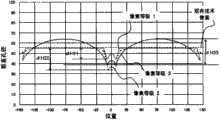
下文中将参考图解表示描述该说明书中估计3D云纹和3D串扰的方法。Hereinafter, the method of estimating 3D moiré and 3D crosstalk in this specification will be described with reference to diagrammatic representations.
图9是示出了本发明的图像显示设备中的示意性亮度分布的图解表示。Fig. 9 is a diagrammatic representation showing a schematic luminance distribution in the image display device of the present invention.
横坐标上的观察位置X表示沿图像分离方向的观察者观察位置。位置0是观察者两眼之间的中点位于从显示平面中心垂直延伸的线上的地方。将明亮度Y绘制为纵坐标。The observation position X on the abscissa indicates the observation position of the observer along the image separation direction.
与输出到左眼的图像相对应的亮度分布出现在观察者位置的-X一侧,与输出至右眼的图像相对应的亮度分布出现在+X一侧。The luminance distribution corresponding to the image output to the left eye appears on the -X side of the observer position, and the luminance distribution corresponding to the image output to the right eye appears on the +X side.
虚线表示当将图像只输出至右眼像素4R和左眼像素4L之一时的亮度分布。Y(LBRW)表示当右边像素显示白色而左边像素显示黑色时所测量的亮度分布。Y(LWRB)表示当右边像素显示黑色而左边像素显示白色时所测量的亮度分布。另外,粗线Y(LWRW)表示当两个像素显示相同图像(右边像素显示白色左边像素也显示白色)时所测量的亮度分布。Y(LBRB)表示当两个像素显示黑色时所测量的亮度分布。A dotted line indicates a luminance distribution when an image is output to only one of the right-
在每一个观察点处由虚线所示的亮度分布Y(LBRW)和L(LWRB)之和等于由粗线表示的亮度分布Y(LWRW),并且以下公式成立。The sum of the luminance distributions Y(LBRW) and L(LWRB) indicated by the dotted line at each observation point is equal to the luminance distribution Y(LWRW) indicated by the thick line, and the following formula holds.
[数学公式21][Mathematical formula 21]
Y(LBRW)+Y(LWRB)=Y(LWRW)Y(LBRW)+Y(LWRB)=Y(LWRW)
亮度分布Y(LBRW)和Y(LWRB)在正前方的观察位置处(即在近似X=0附近)的点(X1,Y1)处交叉。另一方面,在+X一侧上它们在点(XR2,YR2)处交叉,并且在-X一侧上在点(XL2,YL2)处交叉。点(X1,Y1)和(XR2,YR2)之间沿X轴方向的距离等于所投影的右眼图像的宽度eR。点(X1,Y1)与(XL2,YL2)之间沿X轴方向的距离等于所投影的左眼图像的宽度eL。The luminance distributions Y(LBRW) and Y(LWRB) intersect at a point (X1, Y1) at the observation position directly ahead (ie, in the vicinity of approximately X=0). On the other hand, they intersect at the point (XR2, YR2) on the +X side, and at the point (XL2, YL2) on the −X side. The distance along the X-axis direction between the points (X1, Y1) and (XR2, YR2) is equal to the width eR of the projected right-eye image. The distance along the X-axis direction between the points (X1, Y1) and (XL2, YL2) is equal to the width eL of the projected left-eye image.
通过沿X轴方向彼此相邻的子像素之间的边界处的屏蔽部分引起点(X0,Y0)附近的亮度减小。这种亮度减小表现为3D云纹,并且在该说明书中将随后描述的ΔYc和ΔY/ΔX用作3D云纹估计的表示。The decrease in luminance near the point (X0, Y0) is caused by the masking portion at the boundary between sub-pixels adjacent to each other in the X-axis direction. This decrease in luminance appears as 3D moiré, and ΔYc and ΔY/ΔX described later are used as expressions for 3D moiré estimation in this specification.
点(XL1,YL1)是亮度在所投影的左眼图像的宽度eL中具有最大值的地方。点(XR1,YR1)是亮度所投影的右眼图像的宽度eR中具有最大值的地方。点(X0,Y0)是所投影的左眼图像的宽度eL与所投影的右眼图像的宽度eR之间边界附近的亮度分布的最小值。可以根据点(XL1,YL1)和(XR1,YR1)的平均亮度值与点(X0,Y0)的比例,通过以下数学等式表达3D云纹。The point (XL1, YL1) is where the luminance has a maximum value in the width eL of the projected left-eye image. The point (XR1, YR1) is where the width eR of the projected right-eye image of the luminance has a maximum value. The point (X0, Y0) is the minimum value of the luminance distribution near the boundary between the width eL of the projected left-eye image and the width eR of the projected right-eye image. The 3D moiré can be expressed by the following mathematical equation according to the ratio of the average luminance values of the points (XL1, YL1) and (XR1, YR1) to the point (X0, Y0).
[数学公式22][Mathematical formula 22]
YC=(YL1+YR1)/2YC=(YL1+YR1)/2
[数学公式23][Mathematical formula 23]
ΔYc=(YC-Y0)/YCΔYc=(YC-Y0)/YC
[数学公式24][Mathematical formula 24]
ΔY/ΔX=ΔYc/(XR1-XL1)ΔY/ΔX=ΔYc/(XR1-XL1)
另外,左眼图像在所投影的右眼图像的宽度eR中混合,并且右眼图像在所投影的左眼图像的宽度eL中混合。这就是3D串扰。+X区域中的3D串扰可以由以下数学公式表示。In addition, the left-eye image is mixed in the width eR of the projected right-eye image, and the right-eye image is mixed in the width eL of the projected left-eye image. This is 3D crosstalk. The 3D crosstalk in the +X region can be represented by the following mathematical formula.
[数学公式25][Mathematical formula 25]
3DCT(X)=(Y(LBRW)-Y(LBRB))/(Y(LWRB)-Y(LBRB))3DCT(X)=(Y(LBRW)-Y(LBRB))/(Y(LWRB)-Y(LBRB))
另一方面,-X区域中的3D串扰可以由以下数学公式表示。On the other hand, 3D crosstalk in the -X region can be represented by the following mathematical formula.
[数学公式26][Mathematical formula 26]
3DCT(X)=(Y(LWRB)-Y(LBRB))/(Y(LBRW)-Y(LBRB))3DCT(X)=(Y(LWRB)-Y(LBRB))/(Y(LBRW)-Y(LBRB))
通过上述数学公式定义,3D串扰3DCT(X)在点(X1,Y1)、(XL2,YL2)和(XR2,YR2)处最大,并且达到100%的值。另一方面,亮度分布Y(LWRB)和Y(LBRW)在点(XL3,YL3)和(XR3,YR3)处具有最小值,并且3D串扰具有最小值3DCTmin。最小3D串扰3Dmin由以下数学公式定义,并且用作估计的指数。Defined by the above mathematical formula, the 3D crosstalk 3DCT(X) is maximum at the points (X1, Y1), (XL2, YL2) and (XR2, YR2) and reaches a value of 100%. On the other hand, the luminance distributions Y(LWRB) and Y(LBRW) have minimum values at points (XL3, YL3) and (XR3, YR3), and 3D crosstalk has a minimum value 3DCTmin. The minimum 3D crosstalk 3Dmin is defined by the following mathematical formula and used as an index for estimation.
[数学公式27][Mathematical formula 27]
3DCTmin=(YL3-YL4+YR3-YR4)/(2×(Y1-Y2))3DCTmin=(YL3-YL4+YR3-YR4)/(2×(Y1-Y2))
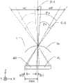
下文中将描述3D串扰3DCT(X)和光斑直径SP之间的关系。图10示出了从子像素发射的光的方向和3D串扰之间的关系。Hereinafter, the relationship between the 3D crosstalk 3DCT(X) and the spot diameter SP will be described. FIG. 10 shows the relationship between the direction of light emitted from a subpixel and 3D crosstalk.
角度范围θs与图9中的右眼观察宽度eR相对应,即与(XR2-X1)相对应。对于角度范围θs,3D串扰在角度范围θt处较低,并且观察者可以观察稳定的三维显示。另一方面,3D串扰在角度范围θr1和θr2中较高,并且观察者可以在观察时体验到不舒服。The angular range θs corresponds to the viewing width eR of the right eye in FIG. 9 , that is, corresponds to (XR2-X1). For the angle range θs, the 3D crosstalk is lower at the angle range θt, and the observer can observe a stable three-dimensional display. On the other hand, 3D crosstalk is high in the angular ranges θr1 and θr2, and the observer may experience discomfort while observing.
获得良好三维效果的角度范围通过从子像素中心附近区域发射的光形成。因此,几乎没有来自沿X轴方向相邻的子像素的影响,并且3D串扰的影响较低。另一方面,角度范围θr1和θr2由从子像素的末端发射的光形成。因此,从沿X轴方向相邻的子像素混合的光增加了3D串扰的影响。因此,观察者不能够获取良好的三维效果。这里,3D串扰从角度范围θs到角度范围θr1连续增加并且波动,三维图像质量下降。类似地,3D串扰从角度范围θs到角度范围θr2连续增加并且波动,三维图像质量下降。然后,3D串扰在角度范围θr1和θr2的中心附近达到100%。这里,θr1和θr2通常近似相等。The angular range for a good three-dimensional effect is formed by emitting light from a region near the center of the sub-pixel. Therefore, there is almost no influence from adjacent sub-pixels in the X-axis direction, and the influence of 3D crosstalk is low. On the other hand, the angular ranges θr1 and θr2 are formed by light emitted from the ends of the sub-pixels. Therefore, light mixed from adjacent sub-pixels in the X-axis direction increases the influence of 3D crosstalk. Therefore, the viewer cannot obtain a good three-dimensional effect. Here, the 3D crosstalk continuously increases and fluctuates from the angle range θs to the angle range θr1, and the three-dimensional image quality deteriorates. Similarly, the 3D crosstalk continuously increases and fluctuates from the angle range θs to the angle range θr2, and the three-dimensional image quality degrades. Then, the 3D crosstalk reaches 100% near the center of the angular ranges θr1 and θr2. Here, θr1 and θr2 are generally approximately equal.
假设光斑直径SP的中心和显示单元4的中心线之间的距离是Xr,那么距离Xr与子像素间距Xdot的比率对应于观察角度范围θr(θr1或θr2)与三维观察范围角度的角度范围θs的关系。以下数学公式成立。Assuming that the distance between the center of the spot diameter SP and the centerline of the
[数学公式28][Mathematical formula 28]
(θs-2×θr)/θs=(Xdot-2×Xr)/Xdot(θs-2×θr)/θs=(Xdot-2×Xr)/Xdot
图11是示出了像素的垂直孔径宽度分布与光斑直径之间关系的图解表示。Fig. 11 is a graphical representation showing the relationship between the vertical aperture width distribution of a pixel and the spot diameter.
当根据垂直孔径宽度分布设置柱面透镜3a的光斑直径SP时,可以通过计算左眼像素4L的孔径所贡献的面积S1(X)与右眼像素4R的孔径区域所贡献的面积Sr(X)之间的面积比来分析地获得3D串扰。假设显示单元4的中心线和光斑直径SP的中心之间沿X轴方向的距离是Xr,以下数学公式成立。When the spot diameter SP of the
[数学公式29][Mathematical formula 29]
3DCT(Xr)=Sr(Xr)/Sl(Xr)3DCT(Xr)=Sr(Xr)/Sl(Xr)
根据上述数学公式可以理解的是,当增加光斑直径SP时,其中3DCT(Xr)保持恒定,显示单元4的中心线与光斑直径SP的中心之间的距离Xr相应地增加。It can be understood from the above mathematical formula that when the spot diameter SP is increased, where 3DCT(Xr) remains constant, the distance Xr between the center line of the
那么根据数学公式28和29,显示单元4的中心线与光斑直径SP的中心之间的距离Xr随着光斑直径SP的增加而增加。因此,减小了其中3D串扰等于或小于3DCT(x)的三维观察范围宽度。Then according to mathematical formulas 28 and 29, the distance Xr between the center line of the
如果3D串扰等于或小于给定值,观察者不会体验到主观上的不舒服。因此,理想的是其中3D串扰等于或小于给定值的角度范围尽可能大。If the 3D crosstalk is equal to or smaller than a given value, the observer does not experience subjective discomfort. Therefore, it is desirable that the angle range in which the 3D crosstalk is equal to or smaller than a given value is as large as possible.
另外,可以通过例如锥光偏振仪、角度计或傅里叶系统来测量3D串扰。具有这种系统的测量装置可以测量相对于视场角度的亮度分布,并且可以而通过随后所述的方法计算3D串扰。来自任何测量装置的定性结果没有什么较大的差别;然而定性数值依赖于测量系统和装置说明而变化。Additionally, 3D crosstalk can be measured by eg conoscopic polarimeters, goniometers or Fourier systems. A measuring device having such a system can measure luminance distribution with respect to an angle of view, and can calculate 3D crosstalk by a method described later. There were no major differences in the qualitative results from any of the measurement devices; however, qualitative values varied depending on the measurement system and device specification.
在本说明书中,使用来自傅里叶系统、EZ对比(Contrast)XL88(例如,ELDIM)的测量结果。这些测量结果与由观察者的主观三维观察范围评估结果之间的比较证实了其中3D串扰等于或小于7.5%的角度范围几乎匹配主观三维观察范围的角度范围。因此,理想的是3D串扰等于或小于7.5%,并且在本说明书中将三维观察范围定义为其中3D串扰等于或小于该值的角度范围。In this description, measurements from a Fourier system, EZ Contrast XL88 (eg, ELDIM) are used. Comparison between these measurement results and the evaluation results of the subjective three-dimensional viewing range by the observer confirmed that the angular range in which the 3D crosstalk is equal to or less than 7.5% almost matches the angular range of the subjective three-dimensional viewing range. Therefore, it is desirable that the 3D crosstalk is equal to or less than 7.5%, and the three-dimensional viewing range is defined in this specification as an angular range in which the 3D crosstalk is equal to or less than this value.
在主观评估时,观察者如图17所述以头部固定在三维观察范围内或者以头部偏移到三维观察范围之外来观察三维图像。根据标准记录多个观察者所体验的主观不舒服。换句话说,记录平均“可见质量”。During subjective evaluation, the observer observes the 3D image with the head fixed within the 3D viewing range or with the head shifted out of the 3D viewing range as shown in FIG. 17 . Subjective discomfort experienced by multiple observers was recorded according to the criteria. In other words, the average "visible quality" is recorded.
另外如图所示,通过光学地分离从每一个像素发射的光并且将光如光束16所示那样偏斜,来形成输出左眼图像的区域和输出右眼图像的区域。通过这样区域与右眼55R和左眼55L之间距离之间的关系来获得三维观察范围。在3D串扰的影响下,使得以上三维观察范围中的左右图像之间边界处的三维可见性劣化。因此,可以将其中3D云纹和3D串扰等于或小于给定值的区域定义为三维可见范围或三维观察范围。Also as shown, by optically separating the light emitted from each pixel and deflecting the light as shown by the
在本说明书中,如上所述,将EZ对照物用于获得图像显示设备的测量。这并非是限制性的,可以使用能够测量沿角度方向的亮度分布的任意测量装置。在这种情况下,理想的是对来自观察者的主观三维观察范围结果进行比较,并且对于所述测量装置确定3D串扰的给定值。In this specification, as described above, EZ controls are used to obtain measurements of image display devices. This is not restrictive, and any measuring device capable of measuring the luminance distribution in the angular direction may be used. In this case, it is desirable to compare the subjective three-dimensional viewing range results from the observer and determine a given value for the 3D crosstalk for the measurement device.
下文中将描述根据该实施例的图像显示设备1的效果。Effects of the
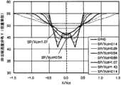
图12(A)是示出了在根据该实施例的像素沿X轴方向的亮度分布和光斑直径SP之间关系的图解表示。图12(B)是示出了图12(A)的一部分的图解表示。图13是示出了在根据该实施例的像素的垂直孔径宽度分布,而图13(B)是示出了亮度分布的图解表示。FIG. 12(A) is a diagrammatic representation showing the relationship between the luminance distribution in the X-axis direction and the spot diameter SP of the pixel according to this embodiment. FIG. 12(B) is a diagrammatic representation showing a part of FIG. 12(A). FIG. 13 is a graph showing the vertical aperture width distribution in the pixel according to this embodiment, and FIG. 13(B) is a diagram showing the luminance distribution.
如图12(A)所示,由于增加的散焦效应,根据该实施例的像素具有随光斑直径SP增加而和缓的亮度分布。当光斑直径SP变得大于Xct/2时,将交叠区域附近的两个分离的最小值组合为一个最小值。减小沿X轴方向的亮度分布的波动(图12(B),如SP/Xct=0.54)。因此,3D云纹变得几乎不可见。这里,根据图13建立来以下数学公式。As shown in FIG. 12(A), the pixel according to this embodiment has a gentle luminance distribution as the spot diameter SP increases due to the increased defocus effect. When the spot diameter SP becomes larger than Xct/2, the two separate minima near the overlapping region are combined into one minima. The fluctuation of the luminance distribution along the X-axis direction is reduced (FIG. 12(B), such as SP/Xct=0.54). As a result, 3D moiré becomes almost invisible. Here, the following mathematical formula is established based on FIG. 13 .
[数学公式30][Mathematical formula 30]
ΔH2/Y1<ΔL/L1<ΔH1/Y1ΔH2/Y1<ΔL/L1<ΔH1/Y1
另外,当光斑直径SP变得大于Xct时,与当光斑直径Sp大于Xct/2(图12(B),如SP/Xct=1.07)相比改善了中心X/Xct=0处的亮度。因此,减小了沿X轴方向的亮度波动,并且改善了中心部分中的亮度,从而3D云纹变得更加不可见。这里,根据图13建立了以下数学公式。In addition, when the spot diameter SP becomes larger than Xct, the luminance at the center X/Xct=0 is improved compared to when the spot diameter Sp is larger than Xct/2 (FIG. 12(B), such as SP/Xct=1.07). Therefore, fluctuations in luminance in the X-axis direction are reduced, and luminance in the central portion is improved, so that 3D moiré becomes less visible. Here, the following mathematical formulas are established based on FIG. 13 .
[数学公式31][Mathematical formula 31]
ΔL/L1<ΔH2/Y1ΔL/L1<ΔH2/Y1
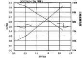
图14是示出了在根据该实施例的像素中的光斑直径SP与亮度波动的幅度ΔYc之间关系的图解表示。图15是示出了在根据该实施例的像素中光斑直径SP和亮度变化的梯度ΔY/ΔX之间关系的图解表示。FIG. 14 is a graphical representation showing the relationship between the spot diameter SP and the magnitude ΔYc of luminance fluctuation in the pixel according to this embodiment. FIG. 15 is a diagrammatic representation showing the relationship between the spot diameter SP and the gradient ΔY/ΔX of the luminance change in the pixel according to this embodiment.
如图所示,当光斑直径如上所述等于或大于Xct/2时,散焦效应有效地发生,并且使严重的亮度变化变平整。另外例如,当光斑直径SP较小时,容易将达到与垂直孔径宽度分布相对应的变化率ΔH1/Y1之前的实际亮度变化看作是3D云纹,使得观察者不舒服。然而,甚至在这种情况下,在显示中心部分中垂直孔径宽度增加的区域有效地平整了亮度分布,从而3D云纹变得几乎不可见。As shown in the figure, when the spot diameter is equal to or larger than Xct/2 as described above, the defocus effect effectively occurs, and severe brightness variations are smoothed out. In addition, for example, when the spot diameter SP is small, it is easy to regard the actual brightness change before reaching the change rate ΔH1/Y1 corresponding to the vertical aperture width distribution as 3D moiré, which makes the observer uncomfortable. However, even in this case, the area where the vertical aperture width is increased in the central portion of the display effectively flattens the luminance distribution so that 3D moiré becomes almost invisible.
图16是示出了在根据该实施例的像素中光斑直径SP与三维观察范围之间关系的图解表示。FIG. 16 is a diagrammatic representation showing the relationship between the spot diameter SP and the three-dimensional viewing range in the pixel according to this embodiment.
如上所述,根据主观估计结果,其中3D串扰等于或小于7.5%的区域是三维观察范围。使用给出3DCT(Xr)=7.5%的光斑直径SP,计算显示单元的中心线和光斑直径的中心之间的距离Xr,从而可以估计三维观察范围宽度的波动率。如图所示,当光斑直径SP是2xXct时,确保了70%或以上的三维观察范围。另外如上所述,当光斑直径SP大于Xct/2时,|ΔY/ΔX|足够小,从而3D云纹变得几乎不可见,并且足够地确保了三维观察范围。因此,为了获得按照稳定的方式在3D云纹和3D串扰之间进行均衡的优秀三维显示特性,可以将光斑直径SP设置在由以下数学公式给出的范围之内。As described above, according to the subjective estimation result, the area in which the 3D crosstalk is equal to or less than 7.5% is the three-dimensional observation range. Using the spot diameter SP which gives 3DCT(Xr)=7.5%, the distance Xr between the center line of the display unit and the center of the spot diameter is calculated so that the fluctuation rate of the three-dimensional observation range width can be estimated. As shown in the figure, when the spot diameter SP is 2xXct, a three-dimensional observation range of 70% or more is ensured. Also as described above, when the spot diameter SP is larger than Xct/2, |ΔY/ΔX| is sufficiently small so that 3D moiré becomes almost invisible, and the three-dimensional observation range is sufficiently secured. Therefore, in order to obtain excellent three-dimensional display characteristics that balance between 3D moiré and 3D crosstalk in a stable manner, the spot diameter SP can be set within the range given by the following mathematical formula.
[数学公式32][Mathematical formula 32]
0.5×Xct<SP<2×Xct0.5×Xct<SP<2×Xct
另外,当光斑直径SP是Xct/4时,根据图14和15可知ΔYc=20%并且ΔY/ΔX=0.03。甚至在这种情况下,主观估计结果证实了所述三维显示特性是主观上可接受的。因此,即使将光斑直径SP设置在由以下数学公式给出的范围之内,也可以获得优秀的三维显示特性。In addition, when the spot diameter SP is Xct/4, it is known from FIGS. 14 and 15 that ΔYc=20% and ΔY/ΔX=0.03. Even in this case, the subjective evaluation results confirmed that the three-dimensional display characteristics were subjectively acceptable. Therefore, even if the spot diameter SP is set within the range given by the following mathematical formula, excellent three-dimensional display characteristics can be obtained.
[数学公式33][Mathematical formula 33]
0.25×Xct<SP<2×Xct0.25×Xct<SP<2×Xct
从所述主观估计结果可以发现:当透镜焦点从像素平面偏移时,优选地,像素平面上的光斑直径SP在WX1/2和2xXct之间的范围内。当光斑直径SP是WX1/2时,梯形孔径的斜边区域是发生模糊的边缘区域。因此,优选地是光斑直径大于WX1/2。当光斑直径SP是2xXct时,模糊区域延伸到垂直孔径宽度恒定的孔径区域。然而,如果模糊区域更大时,透镜的分离性能劣化。因此,当在设计时优先考虑透镜的分离性能时,可以将透镜的曲率半径设置在由以下两个公式给出的范围之内。From the subjective estimation results, it can be found that when the focal point of the lens is shifted from the pixel plane, preferably, the spot diameter SP on the pixel plane is within the range between WX1/2 and 2xXct. When the spot diameter SP is WX1/2, the hypotenuse area of the trapezoidal aperture is the edge area where blurring occurs. Therefore, it is preferable that the spot diameter is larger than WX1/2. When the spot diameter SP is 2xXct, the blurred area extends to the aperture area where the vertical aperture width is constant. However, if the blurred area is larger, the separation performance of the lens deteriorates. Therefore, when the separation performance of the lens is given priority in design, the radius of curvature of the lens can be set within the range given by the following two formulas.
[数学公式34][Mathematical formula 34]
H×L×(n-1)/(L+2×Xct)/n≤r≤H×L×(n-1)/(L+WX1/2)/nH×L×(n-1)/(L+2×Xct)/n≤r≤H×L×(n-1)/(L+WX1/2)/n
[数学公式35][Mathematical formula 35]
H×L×(n-1)/(L-WX1/2)/n≤r≤H×L×(n-1)/(L-2×Xct2)/nH×L×(n-1)/(L-WX1/2)/n≤r≤H×L×(n-1)/(L-2×Xct2)/n
如上所述,根据该实施例的图像显示设备使用设置在范围WX1/2<SP<2xXct内的光斑直径SP,从而有效地应用了散焦效应,并且使得光斑直径SP内的实际亮度变化变平整,从而获得和缓的亮度分布,3D云纹变得不可见,并且可以提供高质量的三维图像。另外,即使增加光斑直径SP以获得和缓的亮度分布,因为交叠区域宽度Xct2小于Xct,3D云纹变得几乎不可见,而不会劣化3D串扰。As described above, the image display device according to this embodiment uses the spot diameter SP set within the range WX1/2<SP<2xXct, thereby effectively applying the defocus effect and flattening the actual luminance variation within the spot diameter SP , so that gentle brightness distribution is obtained, 3D moiré becomes invisible, and high-quality three-dimensional images can be provided. In addition, even if the spot diameter SP is increased to obtain a moderate luminance distribution, since the overlapping region width Xct2 is smaller than Xct, 3D moiré becomes almost invisible without deteriorating 3D crosstalk.
下文中将再次参考图3进行解释。Hereinafter, explanation will be made with reference to FIG. 3 again.
由点A、D和E所包围的三角形屏蔽部分用于减小3D云纹和3D串扰,并且对于改善图像质量有贡献。另一方面,如果屏蔽部分具有较大的面积,并且不能够建立交叠区域宽度Xct2,则孔径比将显著地减小。The triangular shield portion surrounded by points A, D, and E serves to reduce 3D moiré and 3D crosstalk, and contributes to improving image quality. On the other hand, if the shielding portion has a large area, and the overlapping region width Xct2 cannot be established, the aperture ratio will be significantly reduced.
为了防止上述情况并且平衡3D串扰和3D云纹,假定可以建立交叠区域宽度Xct2,那么由点A、D和E所包围的三角形屏蔽部分的面积与由点A、B和C所包围的三角形的面积之比必须等于或小于给定的值。这是通过主观估计结果发现的。更具体地,由点A、D和E所包围的三角形屏蔽部分的面积理想地等于或小于由点A、B和C所包围的三角形的面积,并且理想地等于或小于其30%,以最小化孔径比的减小。In order to prevent the above situation and balance 3D crosstalk and 3D moiré, assuming that the width Xct2 of the overlapping area can be established, then the area of the shielding part of the triangle surrounded by points A, D and E is the same as the area of the triangle surrounded by points A, B and C The ratio of the areas must be equal to or less than the given value. This was found through subjective estimation results. More specifically, the area of the triangular shield portion enclosed by points A, D, and E is ideally equal to or smaller than the area of the triangle enclosed by points A, B, and C, and ideally equal to or less than 30% thereof, with a minimum decrease in aperture ratio.
子像素的垂直孔径宽度沿X轴方向不是恒定的(参见图4和图13)。子像素的垂直孔径宽度一旦从区域Xct朝着显示面板的中心减小,就具有最小值,然后朝着交叠区域宽度Xct2增加。因此,可以相对于沿X轴方向的偏移来减小孔径宽度的波动。The vertical aperture width of the sub-pixel is not constant along the X-axis direction (see FIGS. 4 and 13 ). The vertical aperture width of the sub-pixel has a minimum value as soon as it decreases from the area Xct towards the center of the display panel, and then increases towards the overlapping area width Xct2. Therefore, fluctuations in aperture width can be reduced with respect to shifts in the X-axis direction.
然而例如,如果图3中的点D和F以及点D’和F’在几何上位于相同的位置,则垂直孔径的幅度分布将是恒定的;垂直孔径的幅度不会朝着交叠区域宽度Xct2中的中心线a-a’增加。However, if, for example, points D and F and points D' and F' in Fig. 3 were geometrically at the same location, the amplitude distribution of the vertical aperture would be constant; the amplitude of the vertical aperture would not move towards the width of the overlapping region Centerline a-a' increased in Xct2.
利用垂直孔径宽度的这种分布,不能够获得足够的散焦效应,并且难以使得3D云纹几乎不可见。因此,点D和D’应该分别位于点A和F之间以及点A’和F’之间,即位于交叠区域之内。这种结构可以接受由于工艺精度导致的更大形状变化,提高了生产量并且对于降低成本有贡献。With such a distribution of vertical aperture widths, a sufficient defocus effect cannot be obtained, and it is difficult to make 3D moiré almost invisible. Therefore, points D and D' should be located between points A and F and between points A' and F', respectively, i.e. within the overlapping region. This structure can accept greater shape variation due to process precision, improves throughput and contributes to cost reduction.
由于生产工艺的工艺精度以及TFT基底和相对基底之间的对准变化,具有宽度W的斜金属线沿Y轴方向的波动相对于沿X轴方向的波动是1/sinθ。因此,在该实施例的像素结构中,可以增加金属线的角度θ以改善孔径比,以及增加沿Y轴方向的波动相对于沿X轴方向的波动的余量。另外,即使增加斜金属线的角度θ,也不会使3D串扰劣化,并且同时3D云纹几乎不可见。具体地,本发明的结构优选地可应用于具有100μm或更小子像素间距Xdot的高度精细像素,其中优选地增加角度θ以改善孔径比。根据主观估计结果,斜金属线的最优角度需要至少为17°或以上。Due to the process accuracy of the production process and the alignment variation between the TFT substrate and the opposite substrate, the fluctuation of the oblique metal line having the width W along the Y-axis direction relative to the fluctuation along the X-axis direction is 1/sinθ. Therefore, in the pixel structure of this embodiment, the angle θ of the metal line can be increased to improve the aperture ratio, and increase the margin of the fluctuation along the Y-axis direction relative to the fluctuation along the X-axis direction. In addition, even if the angle θ of the oblique metal wire is increased, the 3D crosstalk is not deteriorated, and at the same time the 3D moiré is hardly visible. Specifically, the structure of the present invention is preferably applicable to highly fine pixels with a subpixel pitch Xdot of 100 μm or less, where the angle θ is preferably increased to improve the aperture ratio. According to subjective estimation results, the optimal angle of the oblique metal wire needs to be at least 17° or above.
一般来说,因为金属线角度是锐角,电场倾向于在近似梯形形状的下底的角落处集中并且干扰液晶的对准,引起来自背光单元的光的泄露。然而在根据该实施例的像素中,屏蔽了锐角部分,减小了泄露光并且改善了对比度。In general, since the wire angle is acute, the electric field tends to concentrate at the corners of the lower base of the approximate trapezoidal shape and interferes with the alignment of liquid crystals, causing leakage of light from the backlight unit. However, in the pixel according to this embodiment, the acute-angle portion is shielded, light leakage is reduced, and contrast is improved.
近似梯形形状的所有角度都是钝角或直角。因此,可以使得由于形成屏蔽部分的方法导致的圆角,并且可以防止由于生产方法导致的孔径比的减小。另外在本发明中,不需要应用高度精确的机械加工工艺来形成锐角部分,实现了低成本。All angles of the approximate trapezoidal shape are obtuse or right angles. Therefore, rounded corners due to the method of forming the shielding portion can be made, and reduction in aperture ratio due to the production method can be prevented. Also in the present invention, it is not necessary to apply a highly precise machining process to form the acute-angled portion, achieving low cost.
在以上解释中,将多个观察点设置在观察平面上,并且从用于显示平面上的所有显示单元的观察点的像素朝着观察点发射光观察。因为将针对特定观察点的光收集到相应的观察点,这种系统称作“光收集系统”。两个观察点的上述图像显示设备以及具有大量观察点的多个观察点的图像显示设备落在光收集系统的种类之下。In the above explanation, a plurality of observation points are set on the observation plane, and light is emitted from pixels for the observation points of all display units on the display plane toward the observation points for observation. Such a system is called a "light collection system" because the light directed to a particular viewpoint is collected to the corresponding viewpoint. The above-mentioned image display apparatus of two observation points and the image display apparatus of a plurality of observation points having a large number of observation points fall under the category of the light collection system.
图17是示出了根据该实施例的图像显示设备的光收集的概念性说明。光收集系统的特征在于再现了进入观察者眼中用于显示的光束。本发明可以有效地应用于这种光收集系统。FIG. 17 is a conceptual illustration showing light collection of the image display device according to this embodiment. The light collection system is characterized by reproducing the light beams that enter the observer's eye for display. The present invention can be effectively applied to such a light collection system.
另外,已经提出了各种系统,并且将它们称作空间图像系统、空间图像再现系统、空间图像再度出现系统、空间图像形成系统等。图18是示出了空间图像系统的概念性说明。与光收集系统不同,空间图像系统不会设置具体的观察点。与光收集系统的区别在于对从空间中的物体发射的光进行再现以用于显示。立体照相系统、立体视频录像系统和立体图像系统落在空间成像系统的种类下。在空间图像系统中,任意位置的观察者不会只观察整个图像平面上的相同观察点的像素。然而,存在由相同观察点的像素形成并且具有给定宽度的多种类型的区域。在每一个区域中,本发明具有与上述光收集系统相同的效果,并且因此有效地应用于空间图像系统。In addition, various systems have been proposed, and they are called aerial image systems, aerial image reproduction systems, aerial image reappearance systems, aerial image forming systems, and the like. FIG. 18 is a conceptual illustration showing an aerial imagery system. Unlike light-collecting systems, aerial imagery systems do not set specific observation points. The difference from light collection systems is the reproduction of light emitted from objects in space for display. Stereoscopic camera systems, stereoscopic video recording systems and stereoscopic imaging systems fall under the category of spatial imaging systems. In a spatial image system, an observer at any position does not only observe the pixels of the same observation point on the entire image plane. However, there are various types of regions formed of pixels of the same viewpoint and having a given width. In each area, the present invention has the same effects as the above-mentioned light collection system, and thus is effectively applied to an aerial image system.
在本发明中,“观察点”并不意味着“显示区域中用户注视的的点(观察点)”,而是意味着“用户从中观察图像显示设备的位置(观察位置)”或者“用户眼睛所处的点或者区域”。In the present invention, "observation point" does not mean "the point at which the user gazes (observation point) in the display area", but means "the position from which the user observes the image display device (observation position)" or "the user's eyes". The point or area where it is located".
另外在根据该实施例的图像显示设备中,偏振片11不需要附着到安装的液晶显示面板上;可以将其设置在双凸透镜3外部。按照这种方式,可以针对偏振片11的厚度来减小像素与透镜之间的距离H。然后,可以取消用于减薄玻璃的抛光工艺。另外,这种布置在设计像素与透镜之间的距离H时允许更大的空间,改善了设计三维观察范围时的自由度。具体地,安装在小装置中的三维显示面板被设计为在面板附近具有最佳的三维显示观察距离,例如在触手可及的范围内。随着像素与透镜之间的距离的减小,可以更加有效地改善三维观察距离。另外,以上布置在小于100μm的像素间距Xunit的高精细项目中是有效的。Also in the image display device according to this embodiment, the
根据该实施例的显示面板的柱面透镜3a可以具有朝向相对基底2b的透镜表面。按照上述相同的方式,随着像素与透镜之间距离的减小,这种结构在改善最佳观察距离的自由度和高精细项目中是有效的。The
另外,图像分离装置可以包括:通过液晶分子控制折射率分布的电光元件,或者由具有透镜效果的凹凸基底液晶分子的组合组成并且使用液晶分子进行切换的电光元件。另外,包括交替设置的透明畴和不透明畴的视差格栅是可用的。视差格栅可以是其中通过液晶分子切换透明和不透明畴的电光元件。In addition, the image separation device may include: an electro-optic element that controls the distribution of refractive index through liquid crystal molecules, or an electro-optic element that is composed of a combination of liquid crystal molecules on a concave-convex substrate with a lens effect and is switched using liquid crystal molecules. In addition, a parallax barrier including transparent and opaque domains arranged alternately is available. A parallax barrier may be an electro-optical element in which transparent and opaque domains are switched by liquid crystal molecules.
另外,当显示面板配置有用于彩色显示的条带图案状滤色器时,优选地是相同颜色的滤色器沿X轴方向连续。按照这样的方式,不需要屏蔽滤色器的相同颜色区域,并且滤色器可以是矩形的。然后,可以容易地生产滤波器,并且图像显示设备实现了更低的成本。In addition, when the display panel is provided with stripe pattern color filters for color display, it is preferable that color filters of the same color are continuous along the X-axis direction. In this way, the same color regions of the color filters need not be masked, and the color filters can be rectangular. Then, the filter can be easily produced, and the image display device achieves lower cost.
另外,滤色器和屏蔽部分可以提供给TFT基底2a。按照这种方式,可以改善交叠精度,从而减小屏蔽部分的宽度,并且改善孔径效率。另外,随着覆盖斜金属线的屏蔽部分的宽度减小,可以减小3D云纹,从而改善显示质量。In addition, a color filter and a shielding portion may be provided to the
另外,利用上述结构,散焦效应用于使由于对准变化导致的亮度分布的剧烈变化平整,从而获得了亮度的和缓分布,并且3D云纹变得几乎不可见,提供了高质量的三维图像。In addition, with the above structure, the defocus effect is used to flatten the drastic change in the luminance distribution due to alignment changes, so that a gentle distribution of luminance is obtained, and 3D moiré becomes almost invisible, providing a high-quality three-dimensional image .
另外,屏蔽部分76可以提供给TFT基底2a上的金属线,而不是在相对于Y轴方向倾斜的一对边之间的区域。利用这种结构,即使沿X轴方向形成具有显著位置误差余量的屏蔽部分,也几乎不会影响孔径比。换句话说,这种结构允许沿X轴的较大位置余量和较高的孔径比。当与其上形成金属线的基底面对的基底上形成屏蔽部分时,这种结构尤为有效。In addition, the shielding
在该实施例中,第一观察点像素是左眼像素4L,而第二观察点像素是右眼像素4R。这并非是限制性的。也可以是第一观察点像素是右眼像素4R,而第二观察点像素是左眼像素4L。按照这种方式,当显示面板2在XY平面内旋转180°时,通过改变图像数据的顺序,可以按照与原始位置相同的方式观察三维显示。具体地,近年来的便携装置具有可旋转显示屏幕用于改善可操作性,要求与手中的图像显示设备1的朝向无关地提供信息。In this embodiment, the first viewpoint pixel is the left-
在该实施例的图像显示设备中安装的液晶面板不局限于TN模式液晶驱动系统,其他液晶驱动模式也是可用的。水平电场模式的示例包括IPS(平面内切换)、FFS(边缘场切换)和AFFS(先进的边缘场切换)系统。另外,垂直对准模式的示例包括MVA(多畴垂直对准,其多畴方案用于减小对于场角度的依赖性)、PVA(图案化垂直对准)和ASV(先进的超级V)系统。另外,优选地可以使用OCB(光学补偿弯曲)系统的液晶显示面板或膜补偿TN模式。The liquid crystal panel mounted in the image display device of this embodiment is not limited to the TN mode liquid crystal drive system, and other liquid crystal drive modes are also available. Examples of horizontal electric field modes include IPS (In-Plane Switching), FFS (Fringe Field Switching) and AFFS (Advanced Fringe Field Switching) systems. In addition, examples of vertical alignment modes include MVA (Multi-Domain Vertical Alignment whose multi-domain scheme is used to reduce dependence on field angle), PVA (Patterned Vertical Alignment) and ASV (Advanced Super V) systems . In addition, a liquid crystal display panel or a film compensation TN mode of an OCB (Optically Compensatory Bend) system can be preferably used.
另外,根据该实施例的显示面板2是使用液晶分子作为电光元件的液晶显示面板。可应用的液晶显示面板不但包括透射液晶显示面板,也包括反射液晶显示面板、半透射液晶显示面板、微反射液晶显示面板(其中透射区域按照比反射区域更大的比率存在)和微透射液晶显示面板(其中反射区域按照比透射区域更大的比率存在)。In addition, the
另外,显示面板驱动方法优选地可应用于TFT系统。TFT系统的可应用薄膜晶体管不但包括那些非晶硅、低温多晶硅、高温多晶硅和单晶硅的晶体管,而且包括那些诸如并五苯之类的有机材料晶体管、诸如氧化锌之类的金属氧化物晶体管和碳纳米管晶体管。另外,本发明优选地可用于底部栅极、顶部栅极、交错和反交错型薄膜晶体管,而与它们的结构无关。In addition, the display panel driving method is preferably applicable to a TFT system. Applicable thin-film transistors for TFT systems include not only those transistors of amorphous silicon, low-temperature polysilicon, high-temperature polysilicon, and single crystal silicon, but also those of organic materials such as pentacene, metal oxide transistors such as zinc oxide, etc. and carbon nanotube transistors. In addition, the present invention is preferably applicable to bottom gate, top gate, staggered and inverse staggered thin film transistors regardless of their structures.
另外,根据该实施例的显示面板2可应用于除了诸如有机电致发光显示面板或PALC(等离子体寻址液晶)之类的液晶类型显示面板之外的显示面板。在有机电致发光显示面板中,非发射区域用作屏蔽区。因此,通过将本发明的屏蔽部分的结构应用于非发射区域,可以获得相同的效果。In addition, the
另外在该实施例中,作为示例,终端装置是蜂窝电话。本发明不局限于此。本发明可应用于多种便携终端装置,例如PDA、个人TV、游戏机、数字摄像机、数字视频照相机和笔记本计算机。另外,本发明不但可应用于便携终端装置,而且可应用于各种固定终端设备,例如自动提款机、自动售货机、监视器和电视接收机。Also in this embodiment, as an example, the terminal device is a cellular phone. The present invention is not limited thereto. The present invention can be applied to various portable terminal devices such as PDAs, personal TVs, game machines, digital video cameras, digital video cameras, and notebook computers. In addition, the present invention is applicable not only to portable terminal devices but also to various stationary terminal devices such as cash dispensers, vending machines, monitors, and television receivers.
[实施例1,修改实施例1][
将参考附图描述根据实施例1的修改实施例的显示面板的像素。A pixel of a display panel according to a modified example of
图19是示出了根据该修改实施例1的显示面板的像素的平面图。FIG. 19 is a plan view showing pixels of a display panel according to Modified Example 1. FIG.
根据该实施例的子像素是梯形的。孔径是近似梯形的,并且配置有近似三角形的屏蔽部分,所述近似三角形屏蔽部分包括锐角部分处的多边形。近似三角形屏蔽部分包括由点A、D、E和F或点A’、D’、E’和F’限定的四边形。The sub-pixels according to this embodiment are trapezoidal. The aperture is approximately trapezoidal, and is configured with an approximately triangular shield portion including a polygon at an acute angle portion. The approximately triangular shield portion includes a quadrilateral defined by points A, D, E, and F or points A', D', E', and F'.
子像素的点F位于交叠区域Xct2中,并且位于由点A、E和D限定固定三角形内部。连接点F和D的线与作为显示面板中心线的线a-a’相交叉。连接点F和D的线与线a-a’之间的角度大于连接点E和F的线与线a-a’之间的角度。The point F of the sub-pixel is located in the overlapping area Xct2 and is located inside a fixed triangle defined by the points A, E, and D. The line connecting the points F and D intersects the line a-a' which is the center line of the display panel. The angle between the line connecting points F and D and the line a-a' is greater than the angle between the line connecting points E and F and the line a-a'.
点D位于由点A、B和C包围的三角形区域外部。点D’位于由点A’、B’和C’所包围的三角形区域外部。因此,点D和D’是垂直孔径宽度沿X轴方向波动的拐点。垂直孔径宽度从这些拐点朝着显示单元4的中心减小。这里,点D和D’之间沿X轴方向的宽度是Xct3。Point D is located outside the triangular area surrounded by points A, B, and C. Point D' is located outside the triangular area enclosed by points A', B', and C'. Thus, points D and D' are inflection points where the vertical aperture width fluctuates in the direction of the X-axis. The vertical aperture width decreases from these inflection points towards the center of the
除了上述内容之外,该修改实施例的图像显示设备1的结构和行为与实施例1的图像显示设备1都相同。The structure and behavior of the
下文中将描述根据该修改实施例的图像显示设备1的效果。Effects of the
连接点F和D的线具有比连接点F和E的线更小的梯度。从点D到点F的垂直孔径宽度的波动比从点F到点E的垂直孔径宽度的波动更小。因此,从点D到点E的导数变化更小。为此原因,利用这种结构,减小了沿X轴方向的亮度分布波动和明亮度分布波动,3D云纹变得几乎不可见,并且包括点A、E、F和D的屏蔽区域用于减小3D串扰。The line connecting points F and D has a smaller gradient than the line connecting points F and E. The fluctuation of the vertical aperture width from point D to point F is smaller than the fluctuation of vertical aperture width from point F to point E. Therefore, the derivative change from point D to point E is smaller. For this reason, with this structure, the luminance distribution fluctuation along the X-axis direction and the luminance distribution fluctuation are reduced, the 3D moiré becomes almost invisible, and the masked area including points A, E, F, and D is used for Reduce 3D crosstalk.
另外,屏蔽部分具有钝角。可以最小化由于形成屏蔽部分的方法导致的圆角。可以防止由于生产方法导致的孔径比的减小。另外,利用这种结构,不需要联合用于形成锐角部分的高精度机械加工工艺,实现了更低的成本。具体地,只存在宽度Xct之内的钝角,减小了由于生产工艺的工艺精度导致的形状变化,并且减小了垂直孔径宽度中的局部波动。In addition, the shielding portion has an obtuse angle. Rounded corners due to the method of forming the shield portion can be minimized. A decrease in the aperture ratio due to the production method can be prevented. In addition, with this structure, it is not necessary to combine high-precision machining processes for forming the acute-angled portion, achieving lower cost. Specifically, there are only obtuse angles within the width Xct, shape variations due to process precision of the production process are reduced, and local fluctuations in the vertical aperture width are reduced.
另外,利用以上结构,可以将包括点A、E、F和D的屏蔽区域用于适当地调节交叠区域Xct2,以便实现对于观察者可接受水平的3D串扰和3D云纹。按照这种方式,甚至对于由100μm或以下的子像素组成的高精细度像素,可以增加设计的自由度。In addition, with the above structure, the shielding area including the points A, E, F, and D can be used to properly adjust the overlapping area Xct2 in order to achieve 3D crosstalk and 3D moiré at an acceptable level for the observer. In this way, even for a high-definition pixel composed of sub-pixels of 100 μm or less, the degree of freedom in design can be increased.
主观估计结果揭示了理想地是包括点A、E、F和D的屏蔽区域占据了10%或更小的孔径比。按照这种方式,最小化了孔径比的减小,并且优化了3D串扰和3D云纹。The subjective estimation results revealed that ideally the shielding area including points A, E, F, and D occupies an aperture ratio of 10% or less. In this way, reduction in aperture ratio is minimized, and 3D crosstalk and 3D moiré are optimized.
近似梯形孔径的锐角部分处的近似三角形屏蔽部分可以包括具有四条或更多边的多边形。在这种情况下,利用除了位于由点A、D和E所限定的三角形内部的点F之外的顶点,从点D到点E的斜边具有和缓的过度。按照这种方式,垂直孔径宽度中的波动是和缓的,并且3D云纹变得不可见。The approximately triangular shield portion at the acute portion of the approximately trapezoidal aperture may include a polygon having four or more sides. In this case, the hypotenuse from point D to point E has a gentle transition with vertices other than point F lying inside the triangle defined by points A, D, and E. In this way, fluctuations in vertical aperture width are smoothed out and 3D moiré becomes invisible.
[实施例1,修改实施例2][
将参考附图描述根据实施例1的修改实施例的显示面板的像素。A pixel of a display panel according to a modified example of
图20是示出了根据该实施例的像素的平面图。FIG. 20 is a plan view showing a pixel according to this embodiment.
根据该实施例的显示面板4包括针对多个观察点的子像素。显示面板4包括沿X轴方向排列的四个子像素4S。显示面板4’和4”每一个也包括沿X轴方向排列的四个像素4S。The
像素40包括沿Y轴方向排列并且在显示区域中排列成矩阵的三个显示单元4、4’和4”。将单个像素中的显示单元4按照这样的方式设置,使得红色R、绿色G和蓝色B滤色器沿X轴方向延伸。四列子像素VX1、VX2、VX3和VX4可以分类针对四个观察点的图像观察并且向作为显示单元的XZ平面输出图像。这里,颜色的顺序不局限于上述情况。可以随机地布置红色R、绿色G和蓝色B的组合。另外,一个像素不局限于上述情况,并且可以包括三个或更多显示单元。在这种情况下,可以使用三种或更多种颜色。The
观察在列VX1中提供与第一观察点相对应的子像素;在列VX2中提供与第二观察点相对应的子像素;在列VX3中提供与第三观察点相对应的子像素;以及在列VX4中提供与第四观察点相对应的子像素。列VX1、VX2、VX3和VX4具备它们各自的间距。这并非是限制性的,并且可以适当地设置。Observing that a subpixel corresponding to a first viewpoint is provided in column VX1; a subpixel corresponding to a second viewpoint is provided in column VX2; a subpixel corresponding to a third viewpoint is provided in column VX3; and Sub-pixels corresponding to the fourth observation point are provided in column VX4. Columns VX1, VX2, VX3, and VX4 have their respective pitches. This is not restrictive and can be set appropriately.
子像素的孔径具有与根据实施例1的显示面板的像素类似的形状。沿与Y轴方向不同的方向倾斜的屏蔽线设置在其边界区域中。换句话说,在沿X轴方向彼此相邻的子像素4S之间提供斜金属线。如在上述实施例中那样,孔径沿Y轴方向彼此交叠的“交叠区域”位于沿X轴方向彼此相邻的子像素4S之间,并且具有交叠宽度Xct2。在子像素的近似梯形孔径的锐角部分处提供近似三角形的屏蔽部分,从而可以将交叠区域宽度Xct2适当地设置为所需宽度。The aperture of the sub-pixel has a shape similar to that of the pixel of the display panel according to
在上述解释中,将3D串扰定义为眼睛之间的串扰。在诸如该修改实施例中的具有三个或更多个观察点的多观察点系统中,可以就“观察点的图像泄露到相邻观察点图像”的意义而言,将3D串扰定义为图像之间的串扰,并且将其称作“图像间串扰”。在如实施例1所述的两个观察点的情况下,眼睛之间的“3D串扰”和“图像间串扰”是相同的,并且3D串扰理想地较低。相反,在多个(三个或更多)观察点的情况下,“图像间串扰”的存在对于产生平滑的互锁视差有贡献,尽管其引起重像;并不总是如所需那样的“图像间串扰”较低。In the above explanation, 3D crosstalk is defined as crosstalk between eyes. In a multi-observation point system with three or more viewpoints such as in this modified embodiment, 3D crosstalk can be defined as image and call it "inter-picture crosstalk". In the case of two viewing points as described in
除了上述内容之外,该修改实施例的图像显示设备1在结构和行为上与实施例1的图像显示设备都相同。The
下文中将描述根据该修改实施例的图像显示设备1的效果。Effects of the
对于具有如实施例1相同形状的子像素,根据该修改实施例的图像显示设备1具有与根据实施例1的图像显示设备等价的效果。The
另外在多个观察点的情况下,随着观察点个数的增加,子像素变得更加精细。因此,由于伴随金属线锐角的电场集中引起的液晶分散对准而导致的泄露光以及由于屏蔽部分形成方法导致的孔径比的减小变得更加明显。In addition, in the case of multiple observation points, as the number of observation points increases, the sub-pixel becomes finer. Therefore, leaked light due to dispersion alignment of liquid crystal caused by electric field concentration accompanying an acute angle of the metal line and reduction of aperture ratio due to shielding portion forming method become more conspicuous.
然而,尽管该修改实施例的子像素用于减小“图像间串扰”,锐角部分处的近似三角形屏蔽部分用于屏蔽,对于改善对比度有贡献。另外,所有的角度都是钝角或直角,从而可以防止由于屏蔽部分形成方法导致的孔径比的减小。However, although the sub-pixels of this modified example are used to reduce "inter-image crosstalk", the approximately triangular masking portion at the acute angle portion is used for masking, contributing to improvement in contrast. In addition, all angles are obtuse or right angles, so that reduction in aperture ratio due to the method of forming the shield portion can be prevented.
在该修改实施例中,描述了由具有四个观察点的显示单元组成的图像显示设备。这并非是限制性的。这种修改实施例可应用于在显示单元中具有N个观察点的三维显示面板。N个观察点的图像显示设备可以利用对于每一个观察点添加最佳三维信息来显示三维图像,从而可以扩展观察优秀三维图像的范围。In this modified embodiment, an image display device composed of a display unit having four viewpoints is described. This is not limiting. This modified embodiment is applicable to a three-dimensional display panel having N observation points in the display unit. The image display device of N observation points can display a three-dimensional image by adding optimal three-dimensional information for each observation point, so that the range of observing excellent three-dimensional images can be expanded.
[实施例2][Example 2]
将参考附图描述根据本发明实施例2的显示面板的像素。A pixel of a display panel according to
图21是示出了该实施例的显示面板的像素的平面图。FIG. 21 is a plan view showing pixels of the display panel of this embodiment.
根据该实施例的显示面板的子像素包括近似梯形孔径和包围近似梯形孔径的梯形屏蔽部分。梯形的锐角部分处的屏蔽部分具有从孔径朝外弯曲的内边缘。The sub-pixel of the display panel according to this embodiment includes an approximately trapezoidal aperture and a trapezoidal shielding portion surrounding the approximately trapezoidal aperture. The shield portion at the acute corner of the trapezoid has an inner edge that curves outward from the aperture.
如下形成屏蔽部分的边缘,使得所述孔径从点D到点E朝外弯曲。所述曲线具有椭圆的曲率。椭圆E1的短轴a具有宽度Y2,长轴b具有等于孔径宽度WXR一半的宽度,即(X1+2xXct2)/2。椭圆E1、E2、E1’和E2’长轴和短轴均相等。换句话说,椭圆E1、E2、E1’和E2’彼此相同,并且在近似梯形形状的锐角部分处提供的屏蔽部分具有相同的曲率。为了减小近似三角形区域的面积以便确保孔径比,理想地是短轴a的宽度小于孔径沿Y轴方向的宽度Y1,而长轴b的宽度是(X1+2xXct2)/2或更大。这里,子像素沿X轴方向的孔径宽度WXR和WXL是子像素中沿X轴方向的孔径宽度的最大值,并且在现有技术结构(参见图36)由X1+2xXct1表示。The edges of the shielding portion are formed such that the aperture curves outward from point D to point E. The curve has the curvature of an ellipse. The minor axis a of the ellipse E1 has a width Y2 and the major axis b has a width equal to half the aperture width WXR, ie (X1+2xXct2)/2. Ellipses E1, E2, E1' and E2' have equal major and minor axes. In other words, the ellipses E1, E2, E1', and E2' are identical to each other, and the shielding portions provided at the acute corner portions of the approximate trapezoidal shape have the same curvature. In order to reduce the area of the approximately triangular region in order to secure the aperture ratio, it is desirable that the width of the minor axis a is smaller than the width Y1 of the aperture in the Y-axis direction, and the width of the major axis b is (X1+2xXct2)/2 or more. Here, the aperture widths WXR and WXL of the subpixel in the X-axis direction are the maximum value of the aperture widths in the X-axis direction in the subpixel, and are represented by X1+2xXct1 in the prior art structure (see FIG. 36 ).
从点D到点E的曲线,即孔径与屏蔽部分之间的边界线与作为显示单元4的中心线的线a-a’相交。The curve from point D to point E, that is, the boundary line between the aperture and the shielding portion intersects the line a-a' which is the center line of the
椭圆E1在点D处内切于近似梯形孔径。因此,垂直孔径宽度相对于X轴方向的导数在点D处连续。Ellipse E1 is inscribed at point D in an approximately trapezoidal aperture. Therefore, the derivative of the vertical aperture width with respect to the X-axis direction is continuous at point D.
点D位于由点A、B和C所包围的三角形区域的外部,也就是点D’。因此,点D和D’是垂直孔径宽度沿X轴方向波动的拐点。垂直孔径宽度从这些拐点朝着显示单元4的中心减小。这里,点D和D’之间沿X轴方向的距离是Xct3。Point D is located outside the triangular area enclosed by points A, B, and C, that is, point D'. Thus, points D and D' are inflection points where the vertical aperture width fluctuates in the direction of the X-axis. The vertical aperture width decreases from these inflection points towards the center of the
除了上述内容之外,该实施例的图像显示设备1与实施例1的图像显示设备1的结构和行为都相同。The
下文中将描述根据该实施例的图像显示设备的效果。Effects of the image display device according to this embodiment will be described below.
垂直孔径宽度相对于X轴方向的导数在点D处连续;因此,点D处垂直孔径宽度的波动是和缓的。因此,明亮光和亮度分布的波动也是和缓的,从而3D云纹变得几乎不可见。The derivative of the vertical aperture width with respect to the X-axis direction is continuous at point D; therefore, the fluctuation of the vertical aperture width at point D is gentle. Therefore, fluctuations in bright light and brightness distribution are also gentle, so that 3D moiré becomes almost invisible.
另外,近似梯形孔径的锐角部分不局限于椭圆的曲率,可以应用高阶函数来产生曲率。In addition, the acute-angled portion of the approximate trapezoidal aperture is not limited to the curvature of the ellipse, and higher-order functions can be applied to generate the curvature.
[实施例3][Example 3]
将参考附图描述根据本发明实施例3的显示面板的像素。A pixel of a display panel according to
图22是示出了根据该实施例的显示面板的像素的平面图。FIG. 22 is a plan view showing pixels of the display panel according to this embodiment.
根据该实施例的显示面板的像素是近似梯形,并且被朝外弯曲的近似梯形孔径的上底和下底遮挡。The pixels of the display panel according to this embodiment are approximately trapezoidal, and are shaded by the outwardly curved upper and lower bases of approximately trapezoidal apertures.
子像素具有由三个椭圆与其正切的四条正切线组成的孔径。所述椭圆是在孔径的中心部分具有中心的椭圆E5和E5’,以及在近似梯形形状的下底处的两个椭圆E3或E3’和E4或E4’。椭圆E5和E5’相同。椭圆E3和E3’以及E4和E4’分别相同。A subpixel has an aperture consisting of three ellipses and four tangents to which it is tangent. The ellipses are ellipses E5 and E5' having a center in the central part of the aperture, and two ellipses E3 or E3' and E4 or E4' at the lower base of the approximate trapezoidal shape. Ellipses E5 and E5' are identical. The ellipses E3 and E3' and E4 and E4' are respectively the same.
点D、E和F是线与椭圆之间的正切点。在每一个点处,垂直孔径宽度相对于X轴方向的导数连续。Points D, E and F are the tangent points between the line and the ellipse. At each point, the derivative of the vertical aperture width with respect to the X-axis direction is continuous.
椭圆E3的短轴c大于垂直孔径宽度Y1。垂直孔径宽度在子像素的中心线处最大。这里,在近似梯形孔径的下底处与Y轴垂直的斜边宽度是恒定的。这并非是限制性的。可以根据垂直孔径宽度的变化改变斜边宽度。The minor axis c of the ellipse E3 is greater than the vertical aperture width Y1. The vertical aperture width is greatest at the centerline of the sub-pixel. Here, the width of the hypotenuse perpendicular to the Y-axis at the lower base of the approximately trapezoidal aperture is constant. This is not limiting. The hypotenuse width can be changed according to the change of vertical aperture width.
连接右眼像素4R中的四个点A、B、A”和B”的梯形称作参考梯形T。连接三个点A、D和E的屏蔽区域(下文中称作Sa)和连接三个点A”、D”和E”的屏蔽区域(下文中称作Sa’)在参考梯形T的锐角部分处形成。连接三个点B、G和F的屏蔽区域(下文中称作Tb)和连接三个点B”、G”和F”的屏蔽区域(下文中称作Sb’)在参考梯形T的钝角部分处形成。A trapezoid connecting four points A, B, A" and B" in the right-
另一方面,在参考梯形T的上底处超出垂直孔径宽度Y1的区域,即由点G、I和G”包围的区域(下文中称作Sc)是新提供在参考梯形T外部的孔径区域,并且对于孔径比的改善有贡献。On the other hand, the area beyond the vertical aperture width Y1 at the upper base of the reference trapezoid T, that is, the area surrounded by points G, I, and G" (hereinafter referred to as Sc) is an aperture area newly provided outside the reference trapezoid T , and contribute to the improvement of the aperture ratio.
这里,区域Sc大于上述屏蔽区域的总面积。换句话说Sc>Sa+Sa’+Sb+Sb’。因此整体上来说,改善了子像素的孔径比。这同样也适用于左眼像素4L。Here, the area Sc is larger than the total area of the shielding areas described above. In other words Sc>Sa+Sa'+Sb+Sb'. Therefore, overall, the aperture ratio of the sub-pixel is improved. The same applies to the
除了上述内容之外,该实施例的图像显示设备1与实施例1的图像显示设备1的结构和行为都相同。The
下文中将描述根据该实施例的图像显示设备1的效果。Effects of the
垂直孔径宽度相对于X轴方向的导数在椭圆接触线条的点处是连续的,因此上述接触点处的垂直孔径宽度的波动是和缓的。因此,明亮度和亮度分布的波动也是和缓的,从而3D云纹变得几乎不可见。The derivative of the vertical aperture width with respect to the X-axis direction is continuous at the point where the ellipse touches the line, so the fluctuation of the vertical aperture width at the above contact point is gentle. Therefore, fluctuations in luminance and luminance distribution are also gentle, so that 3D moiré becomes almost invisible.
另外,提供由点G、I和G”所包围的区域,并且所述区域的面积大于屏蔽区域的总面积,从而改善了孔径比。In addition, an area surrounded by the points G, I, and G" is provided, and the area of the area is larger than the total area of the shielding area, thereby improving the aperture ratio.
下文中将比较上述结构,并且将讨论其效果。在现有技术实施例和实施例1、2和3中进行比较。Hereinafter, the above structures will be compared and their effects will be discussed. Comparisons were made between the prior art example and examples 1, 2 and 3.
首先,将现有技术实施例的像素称作“现有技术像素”,将实施例1的像素称作“像素等级1”;将实施例2的像素称作“像素等级2”;以及将实施例3的像素称作“像素等级3”。First, the pixel of the prior art embodiment is referred to as "prior art pixel", the pixel of
图23是示出了在每一个像素等级中的垂直孔径宽度分布的图解表示,其中将垂直孔径宽度绘制为纵坐标,将沿X轴方向的位置绘制为横坐标。Fig. 23 is a graphical representation showing the vertical aperture width distribution in each pixel level, where the vertical aperture width is plotted as the ordinate and the position along the X-axis direction is plotted as the abscissa.
像素等级3的垂直孔径宽度的最大值与最小值之间的差ΔH33近似等于像素等级2的垂直孔径宽度的最大值与最小值之间的差/ΔH22。与那些差相比,像素等级1的垂直孔径宽度的最大值与最小值之间的差ΔH11更小。现有技术像素没有垂直孔径宽度波动。The difference ΔH33 between the maximum and minimum vertical aperture widths for
图24是示出了相对于图23所示像素等级的垂直孔径宽度分布的X轴方向的导数。FIG. 24 is a graph showing the derivative in the X-axis direction with respect to the vertical aperture width distribution at the pixel level shown in FIG. 23 .
像素等级3相对于X轴方向波动的导数小于像素等级2相对于X轴方向的像素等级2的导数。像素等级1和2的导数朝着中心位置剧烈地波动。另一方面,像素等级3的导数不会朝着中心位置剧烈地波动;它们连续地波动。像素等级3的垂直孔径宽度相对于X轴方向的导数在点E、C和D处是连续的(参见图22);因此,垂直孔径宽度中的波动在这些点处是和缓的,从而3D云纹变得几乎不可见。The derivative of
图25是示出了应用上述像素等级的像素的图像显示设备的评估结果的表。在表中,符号(双圆形、○,△,x)表示主观评估结果。“双圆形”表示在观察期间没有3D串扰/3D云纹是可见的,并且不会感觉到不舒服。符号“○”表示在观察期间有一点3D串扰/3D云纹是可见的,但是不会感觉到不舒服。符号“△”表示只要在3D串扰/3D云纹优化观察范围内观察三维显示,就不会感觉到不舒服。符号“x”表示3D串扰/3D云纹引起明显感觉到不舒服,并且可见性下降。FIG. 25 is a table showing evaluation results of an image display device to which pixels of the above-described pixel class are applied. In the table, symbols (double circles, ◯, △, x) indicate subjective evaluation results. "Double circle" means that no 3D crosstalk/3D moiré is visible during observation and no discomfort is felt. The symbol "○" indicates that a little 3D crosstalk/3D moiré is visible during observation, but no discomfort is felt. The symbol "△" indicates that as long as the 3D display is observed within the 3D crosstalk/3D moire optimized viewing range, you will not feel uncomfortable. The symbol "x" indicates that the 3D crosstalk/3D moiré causes a distinct feeling of discomfort, and the visibility is reduced.
参考图表,现有技术像素成功地减小了3D云纹,但是没有减小3D串扰,使图像质量劣化。Referring to the graph, the prior art pixels successfully reduce 3D moiré, but fail to reduce 3D crosstalk, deteriorating image quality.
相反地,应该理解的是根据本发明的像素不但减小了3D云纹,而且减小了3D串扰,实现了均衡的图像,并且改善了图像质量。On the contrary, it should be understood that the pixel according to the present invention not only reduces 3D moiré, but also reduces 3D crosstalk, realizes a balanced image, and improves image quality.
[实施例3,修改实施例1][
将参考附图描述根据本发明实施例3的修改实施例的显示面板的像素。A pixel of a display panel according to a modified example of
图26是示出了根据该修改实施例的显示面板的像素的平面图。FIG. 26 is a plan view showing pixels of a display panel according to the modified example.
子像素关于线b-b’不对称,而关于显示单元4的中心O对称。子像素的孔径在近似梯形像素的上底和下底处朝外弯曲,并且具有使垂直孔径比最大化的最大值。The sub-pixels are not symmetrical about the line b-b', but symmetrical about the center O of the
图27(A)示出了根据该修改实施例的垂直孔径比分布,以及图27(B)示出了根据该修改实施例的像素的明亮度分布。如图所示,垂直孔径宽度在透镜凸起部分处的一侧上最大化,所示透镜凸起部分是透镜的主轴,并且同时使明亮度最大化。FIG. 27(A) shows a vertical aperture ratio distribution according to this modified example, and FIG. 27(B) shows a brightness distribution of a pixel according to this modified example. As shown, the vertical aperture width is maximized on one side at the lens convex portion, which is the main axis of the lens, and brightness is maximized at the same time.
除了上述内容之外,该修改实施例的图像显示设备1与实施例1的图像显示设备1在结构和行为上都相同。The
下文中将描述根据该修改实施例的图像显示设备1的效果。Effects of the
如图27(B)所示,垂直孔径宽度在透镜主轴附近的侧面上具有最大值I和I’。因此,由透镜分离有效宽度定义的Xct2的亮度波动ΔL,即光斑直径SP变得相对较小,并且减小了3D云纹。As shown in Fig. 27(B), the vertical aperture width has the maximum values I and I' on the sides near the main axis of the lens. Therefore, the luminance fluctuation ΔL of Xct2 defined by the lens separation effective width, that is, the spot diameter SP becomes relatively small, and the 3D moiré is reduced.
另外一般来说,通过金属成型、光刻或喷墨技术生产双凸透镜3。利用任意技术,更加确保柱面透镜3a的透镜凸起部分31比相邻柱面透镜3a的透镜凹陷部分32具有给定的形状,并且透镜凸起部分31具有更好的光学性能。另外,从透镜凹陷部分比从透镜凸起部分31更加难以去除任意残留物或粘附性外部材料,降低了透镜凹陷部分的光学分离效果。Also in general, the
甚至当将GRIN(梯度折射率)透镜用作使用液晶作为光学装置的电光元件时,例如双凸透镜3,折射率在透镜凹陷部分32比在透镜凸起部分31处变化地更厉害,降低了透镜凹陷部分32的光学分离效果。Even when a GRIN (Gradient Refractive Index) lens is used as an electro-optic element using liquid crystal as an optical device, such as a
另外例如,即使使用除了GRIN透镜之外的透镜,例如使用由具有透镜效果的凹凸基底与液晶分子的组合组成的液晶透镜,凹凸基底具有与透镜凹陷部分32相对应的陡峭凸起部分,降低了光学分离效果。Also, for example, even if a lens other than the GRIN lens is used, for example, a liquid crystal lens composed of a combination of a concave-convex base having a lens effect and liquid crystal molecules is used, the concave-convex base has a steep convex portion corresponding to the lens
然而在根据该修改实施例的像素中,在透镜凸起部分31附近的一侧上增加垂直孔径宽度,从而可以将从子像素发射的光分配给具有高光学分离性能的透镜凸起部分31。因此,根据该修改实施例的像素防止了由诸如双凸透镜之类的光学装置和使用液晶的电光元件引起的三维图像质量劣化,从而进一步有效地利用了光,对于改善透射率和三维图像质量有贡献。However, in the pixel according to this modified example, the vertical aperture width is increased on the side near the lens
[实施例4][Example 4]
将参考附图描述根据本发明实施例4的显示面板的像素。A pixel of a display panel according to
图28是示出了该实施例的显示面板的像素的平面图。FIG. 28 is a plan view showing pixels of the display panel of this embodiment.
根据该实施例的子像素是梯形,并且具有近似梯形的孔径。在子像素的近似梯形形状的锐角部分处提供的近似三角形屏蔽部分在各个锐角部分中具有不同的结构。按照这样的方式,所述孔径关于子像素的中心线b-b’不对称,并且关于显示面板4的中心O对称。The sub-pixels according to this embodiment are trapezoidal and have approximately trapezoidal apertures. The approximately triangular shielding portions provided at the acute-angled portions of the approximately trapezoidal shape of the sub-pixel have different structures in the respective acute-angled portions. In this way, the aperture is asymmetric about the center line b-b' of the sub-pixel and symmetrical about the center O of the
如上所述,双凸透镜3由柱面透镜3a组成,所述柱面透镜3a沿X轴方向排列,并且形成了透镜凸起部分31之间的透镜凹陷部分32。透镜凸起部分31和透镜凹陷部分32沿X轴方向交替地排列。这里如上述实施例中那样,光学装置可以是由使用液晶的电光元件组成的透镜。As described above, the
在透镜凹陷部分32处提供与显示单元4的末端相对应的斜金属线。在透镜凸起部分31处提供显示单元4的中心处的斜金属线。这里,显示单元4的末端处以锐角提供的近似三角形屏蔽部分与显示面板4的中心处在锐角部分处提供的近似三角形屏蔽部分不同。An oblique metal line corresponding to the end of the
根据该实施例的像素防止了由上述诸如双凸透镜之类的光学装置和使用液晶的电光元件引起的三维图像质量劣化。The pixel according to this embodiment prevents the deterioration of three-dimensional image quality caused by the aforementioned optical devices such as lenticular lenses and electro-optical elements using liquid crystals.
显示单元4彼此相邻的交叠区域宽度Xct2’或Xct2”比显示单元4的中心处交叠区域宽度Xct2更小。换句话说,具有较低光学分离性能的透镜凹陷部分32处的交叠区域宽度Xct2’或Xct2”比透镜凸起部分31处的交叠区域宽度Xct2更小,并且由以下数学公式表达。The overlapping region width Xct2' or Xct2" where the
[数学公式36][Mathematical formula 36]
Xct2’<Xct2Xct2'<Xct2
[数学公式37][Mathematical formula 37]
Xct2”<Xct2Xct2"<Xct2
除了上述内容之外,该实施例的图像显示设备1在结构和行为上与实施例1的图像显示设备1相同。The
下文中将描述根据该实施例的图像显示设备1的效果。Effects of the
在透镜凹陷部分32处,光斑直径SP较大,并且光学分离性能较低。由于交叠区域宽度Xct2’和Xct2”更小,可以调节与透镜凸起部分31的均衡。At the lens
可以将从子像素发射的光分配给具有较高光学分离性能的透镜凸起部分31。因此,根据该实施例的图像显示设备防止了由诸如双凸透镜之类的光学装置和使用液晶的电光元件引起的三维图像质量的劣化。可以更加有效地使用光,对于透射率和三维图像质量的改善有贡献。Light emitted from the sub-pixels can be distributed to the lens
在根据该实施例的图像显示设备中,在子像素的锐角部分处提供的近似三角形屏蔽部分用于使得3D云纹几乎不可见,并且减小了3D串扰。In the image display device according to this embodiment, the approximately triangular shielding portion provided at the acute angle portion of the sub-pixel serves to make 3D moiré almost invisible and reduce 3D crosstalk.
[实施例5][Example 5]
将参考附图描述根据本发明实施例5的显示面板的像素。A pixel of a display panel according to Embodiment 5 of the present invention will be described with reference to the drawings.
图29是示出了该实施例的显示面板的像素的平面图。FIG. 29 is a plan view showing pixels of the display panel of this embodiment.
根据该实施例的子像素是梯形,并且具有近似梯形的孔径。所述孔径关于显示单元4的中心O对称。The sub-pixels according to this embodiment are trapezoidal and have approximately trapezoidal apertures. The aperture is symmetrical about the center O of the
如在上述实施例中那样,在近似梯形形状的锐角部分处提供的近似三角形屏蔽部分在梯形的各个锐角部分处具有不同的结构。显示单元4彼此相邻的部分的交叠区域宽度Xct2’或Xct2”比显示单元4的中心处的交叠区域宽度Xct2更大。换句话说,具有较低光学分离性能的透镜凹陷部分32处的交叠区域宽度Xct2’或Xct2”比透镜凸起部分31处的交叠区域宽度Xct2更大,并且由以下数学公式表达。As in the above-described embodiments, the approximately triangular shield portions provided at the acute corner portions of the approximately trapezoidal shape have different structures at the respective acute corner portions of the trapezoidal shape. The overlapping region width Xct2' or Xct2" of the portion where the
[数学公式38][Mathematical formula 38]
Xct2’>Xct2Xct2'>Xct2
[数学公式39][Mathematical formula 39]
Xct2”>Xct2Xct2”>Xct2
图30是示出了根据该实施例的图像显示设备1的光学模型的示意性说明。FIG. 30 is a schematic illustration showing an optical model of the
与上述实施例中的显示面板相比,显示面板2具有更大的观察宽度eR’和EL’。为了增加观察宽度,由数学公式5至13所表达的,调节双凸透镜3的折射率n以及柱面透镜3a与像素之间的距离H,以获得所需宽度。Compared with the display panels in the above embodiments, the
再次参考图29,在显示单元4中心处的近似梯形孔径的锐角部分处提供近似三角形屏蔽部分。交叠区域宽度Xct2小于Xct。另外,在沿X轴方向彼此相邻的显示单元之间的交叠区域中,在近似梯形孔径的锐角部分处没有提供屏蔽部分,从而增加了Xct2’和Xct2”以改善孔径比。Referring again to FIG. 29 , an approximately triangular shield portion is provided at the acute corner portion of the approximately trapezoidal aperture at the center of the
利用上述结构,如图30所示,θr1大于θr2。然而,减小距离H以增加观察宽度eR’和eL’。因此,确保了对于三维观察范围有贡献的光束角度θt具有给定的值,而不会损害三维观察范围。With the above structure, as shown in FIG. 30, θr1 is larger than θr2. However, the distance H is decreased to increase the observation widths eR' and eL'. Therefore, it is ensured that the beam angle θt that contributes to the three-dimensional viewing range has a given value without impairing the three-dimensional viewing range.
除了上述内容之外,该实施例的图像显示设备1与实施例1的图像显示设备1的结构和行为都相同。The
下文中将描述根据该实施例的图像显示设备1的效果。Effects of the
根据该实施例的图像显示设备1在显示单元4的中心处具有屏蔽部分,从而获得了优秀的显示特性,包括三维视场的中心部分处均衡的3D串扰和3D云纹。另外,因为增加了观察宽度并且在沿X轴方向彼此相邻的显示单元之间不存在屏蔽部分,可以在不损害三维观察范围的情况下改善孔径比。The
另外,根据与透镜凹陷部分32相对应的显示单元4末端处的较大交叠区域宽度Xct2’和Xct2”与透镜凹陷部分32处的较大光斑直径之间的协同效果,产生了三维观察明显困难的区域。In addition, according to the synergistic effect between the larger overlapping area widths Xct2' and Xct2" at the end of the
当三维观察困难的角度范围θr2较小时,观察者可以体验所谓的“翻转”状态,其中如果他/她从非正前方的位置观察的话,右眼图像和左眼图像无意切换。翻转状态中的观察不是优选的,因为其引起眼睛疲劳或不舒服。然而,利用上述结构,三维观察在角度范围θr2时明显困难,并且这种角度范围较大;因此可以防止上述翻转观察。因此,可以提供高度安全的三维图像。When the angular range θr2 where three-dimensional viewing is difficult is small, the observer may experience a so-called "flip" state in which the right-eye image and the left-eye image switch unintentionally if he/she observes from a position other than straight ahead. Viewing in the flipped state is not preferable because it causes eye fatigue or discomfort. However, with the above-mentioned structure, three-dimensional observation is significantly difficult in the angle range θr2, and this angle range is large; therefore, the above-mentioned inverted observation can be prevented. Therefore, highly secure three-dimensional images can be provided.
在实施例3、实施例4和实施例5的修改实施例1中,第一观察点像素4L和第二观察点像素4R组成了显示单元,并且光学装置的高光学分离性能区位于显示单元内,低光学分离性能区位于显示单元之间。这不是限制性的。例如,屏蔽部分的形状可以根据屏蔽部分是位于显示单元内还是位于显示单元之间而不同。这种结构可以防止由于光学装置导致的三维图像质量的劣化,并且允许进一步有效地使用光,从而对于改善透射率和三维图像质量有贡献。In Modified Example 1 of
[实施例6][Example 6]
将参考附图描述根据本发明实施例6的显示面板的像素。A pixel of a display panel according to
图31是示出了该实施例的显示面板的像素的平面图。FIG. 31 is a plan view showing pixels of the display panel of this embodiment.
根据该实施例的子像素具有平行四边形形状。子像素具有由与X轴近似平行的两条边和相对于Y轴方向成角度θ的两条斜边组成的近似平行四边形孔径。子像素沿X轴方向和Y轴方向排列成矩阵。换句话说,任意子像素的斜边总是按照相同的倾角θ。因此,与实施例1中所述的像素结构不同,显示单元4关于与Y轴平行并且穿过子像素中心的线b-b’不对称。然而,关于显示单元4的中心O是对称的,并且在XY平面内旋转180°之后具有等价的布局结构。The sub-pixel according to this embodiment has a parallelogram shape. The sub-pixel has an approximately parallelogram aperture composed of two sides approximately parallel to the X-axis and two hypotenuses forming an angle θ with respect to the Y-axis direction. The sub-pixels are arranged in a matrix along the X-axis direction and the Y-axis direction. In other words, the hypotenuse of any sub-pixel is always at the same inclination θ. Therefore, unlike the pixel structure described in
像素40由沿Y轴方向排列的三个显示单元4、4’和4”组成。显示单元按照红色R、绿色G或蓝色B着色。像素40是正方形的,并且在显示区域中排列成沿X轴方向间距Xunit和沿Y轴方向间距Yunit的矩阵。另外,子像素沿X轴方向的间距Xdot是Xunit/2,并且子像素沿Y轴方向的间距Ydot是Xpix/3。红色R、绿色G、蓝色B滤色器沿X轴方向延伸,并且产生沿Y轴方向重复的近似条形图案。The
沿X轴方向排列的子像素的孔径沿Y轴方向没有偏移。平行四边形的下底处的屏蔽部分沿Y轴方向也没有偏移。按照这种方式,平行四边形下底处的屏蔽部分形成沿X轴方向从显示区域的一端到另一端延伸的屏蔽部分的带。换句话说,多边形像素的下底处的屏蔽部分的宽度Y2近似恒定,沿X轴方向没有波动。The apertures of the sub-pixels arranged in the X-axis direction are not shifted in the Y-axis direction. The shield portion at the lower base of the parallelogram is also not shifted in the Y-axis direction. In this way, the shield portion at the lower base of the parallelogram forms a band of shield portions extending from one end to the other end of the display area in the X-axis direction. In other words, the width Y2 of the masked portion at the lower base of the polygonal pixel is approximately constant without fluctuation along the X-axis direction.
另外,在近似多边形孔径的锐角部分处提供近似三角形屏蔽区域。In addition, an approximately triangular shielding area is provided at the acute-angled portion of the approximately polygonal aperture.
除了上述内容之外,该实施例的图像显示设备1与实施例1的图像显示设备1的结构和行为都相同。The
下文中将描述根据该实施例的图像显示设备1的效果。Effects of the
根据该实施例的图像显示设备1在平行四边形孔径的锐角部分处具有屏蔽部分,减小了3D串扰并且减小了垂直孔径宽度中的波动,以使得3D云纹几乎不可见。The
普通液晶面板控制一个基底上沿一个方向的磨损。因此,如果每一个子像素包括相对于磨损方向的非对称结构,显示特性基于子像素而变化,这种变化表现为具体地在图像显示设备中的观察点之间的显示特性的差别。Ordinary liquid crystal panels control wear in one direction on one substrate. Therefore, if each sub-pixel includes an asymmetrical structure with respect to the wear direction, display characteristics vary on a sub-pixel basis, and this variation appears as a difference in display characteristics between observation points particularly in an image display device.
然而,根据该实施例的显示单元包括单一外部形状的子像素,减小了子像素之间的参差结构中的差别或电场分布结构差异,并且减小了由于子像素形状之差导致的观察点之间的显示特性的差异。另外利用上述结构,子像素相等的取向,可以稳定施加电压时的液晶对准。换句话说,可以减小观察点之间图像质量的差异,并且将均匀图像输出至观察点以提供高质量的三维图像。另外,因为子像素是单一的形状,在每一个子像素中稳定了液晶分子的对准,减小了未对准或者泄露光,并且改善了对比度。However, the display unit according to this embodiment includes sub-pixels of a single outer shape, the difference in the jagged structure or the difference in the electric field distribution structure between the sub-pixels is reduced, and the observation point due to the difference in the shape of the sub-pixels is reduced. Differences in display characteristics between. In addition, with the above-mentioned structure, the alignment of the sub-pixels is equal, and the alignment of the liquid crystal when a voltage is applied can be stabilized. In other words, it is possible to reduce the difference in image quality between observation points, and output a uniform image to the observation points to provide a high-quality three-dimensional image. In addition, since the sub-pixels are of a single shape, alignment of liquid crystal molecules is stabilized in each sub-pixel, misalignment or light leakage is reduced, and contrast is improved.
依赖于像素尺寸和屏蔽区域面积,可以通过图像分离装置光学地增加某些局部屏蔽宽度,并且有时光暗颗粒对于人眼变得可见,这降低了图像质量。然而,在该实施例的显示单元中,平行四边形下底处的屏蔽宽度沿X轴方向近似恒定,即沿图像分离方向,从而可以减小根据屏蔽宽度的波动导致的光暗颗粒。Depending on the pixel size and masking area area, some local masking width can be optically increased by the image separation device, and sometimes light and dark particles become visible to the human eye, which degrades the image quality. However, in the display unit of this embodiment, the mask width at the lower base of the parallelogram is approximately constant along the X-axis direction, ie, along the image separation direction, so that light and dark particles caused by fluctuations in the mask width can be reduced.
另外,使用诸如IPS(平面内切换)、FFS(边缘场切换)和AFFS(先进的边缘场切换)系统之类的水平或倾斜电场的液晶驱动模式可以通过使用单一畴来改善透射率,在所述单一畴中液晶分子相等地旋转。因此优选地,该实施例的像素结构是可用的。In addition, liquid crystal driving modes using horizontal or inclined electric fields such as IPS (In-Plane Switching), FFS (Fringe Field Switching), and AFFS (Advanced Fringe Field Switching) systems can improve transmittance by using a single domain, at all The liquid crystal molecules in the single domain rotate equally. Therefore preferably, the pixel structure of this embodiment is usable.
[实施例7][Example 7]
将参考附图描述根据本发明实施例7的显示面板的像素。A pixel of a display panel according to Embodiment 7 of the present invention will be described with reference to the drawings.
图32是示出了根据该实施例的显示面板的像素的平面图。FIG. 32 is a plan view showing pixels of the display panel according to this embodiment.
根据该实施例的子像素是平行四边形形状,并且具有近似平行四边形形状。所述近似平行四边形形状包括由与X轴近似平行的两条边和相对于Y轴成-θ或+θ倾角的两条斜边组成的两个近似矩形形状。那么,与实施例1中所述的像素结构不同,该结构关于与Y轴平行并且穿过子像素中心的线b-b’不对称,但是关于显示单元4的中心O对称。The sub-pixels according to this embodiment are parallelogram-shaped, and have an approximate parallelogram-shaped shape. The approximately parallelogram shape includes two approximately rectangular shapes composed of two sides approximately parallel to the X axis and two hypotenuses at an inclination of -θ or +θ with respect to the Y axis. Then, unlike the pixel structure described in
另外与上述实施例不同,沿Y轴方向彼此相邻的子像素可以沿彼此不同的方向对准液晶分子。那么,多畴补偿效应用于当沿斜方向查看时减小色调变化。In addition, unlike the above-mentioned embodiments, sub-pixels adjacent to each other along the Y-axis direction can align liquid crystal molecules in different directions from each other. The multi-domain compensation effect is then used to reduce hue variation when viewed obliquely.
沿Y轴方向交替地设置具有倾角+θ(>0)的斜边的近似平行四边形子像素和具有倾角-θ(<0)的斜边的近似平行四边形子像素。沿X轴方向设置具有相同倾角的斜边的子像素。沿Y轴方向设置的子像素的斜边在每一行转变方向,同时沿X轴方向设置的子像素的斜边按照相同的角度倾斜。Approximately parallelogram sub-pixels having hypotenuses with an inclination +θ (>0) and approximately parallelogram sub-pixels having hypotenuses with an inclination -θ (<0) are alternately arranged along the Y-axis direction. Sub-pixels with hypotenuses having the same inclination are arranged along the X-axis direction. The hypotenuses of the sub-pixels arranged in the Y-axis direction switch direction every row, while the oblique sides of the sub-pixels arranged in the X-axis direction are inclined at the same angle.
像素电极4PIX和相对电极4COM形成在电极对4PAIR,所述电极对与沿不同于Y轴方向的方向倾斜的长度方向近似平行地排列。在该实施例中,根据平行四边形的斜边,将电极对4PARI相对于Y轴方向的倾斜角设置为-θ或+θ。所述电极对4PAIR和子像素斜边处的斜金属线彼此平行。The pixel electrode 4PIX and the counter electrode 4COM are formed in an electrode pair 4PAIR arranged approximately in parallel with the length direction inclined in a direction different from the Y-axis direction. In this embodiment, the inclination angle of the electrode pair 4PARI with respect to the Y-axis direction is set to -θ or +θ according to the hypotenuse of the parallelogram. The electrode pair 4PAIR and the oblique metal line at the oblique side of the sub-pixel are parallel to each other.
在子像素沿X轴方向提供由像素电极4PIX和相对电极4COM构成的多个电极对4PAIR,以在每一个子像素的孔径中沿与电极对4PAIR的倾斜方向垂直的方向创建电场。在像素电极4PIX和相对电极4COM之间创建的电场至少包括与基底表面精确平行的分量,从而可以在与基底表面近似平行的表面内旋转液晶分子51的主轴。A plurality of electrode pairs 4PAIR composed of a pixel electrode 4PIX and a counter electrode 4COM are provided in the sub-pixel along the X-axis direction to create an electric field in the aperture of each sub-pixel in a direction perpendicular to the inclination direction of the electrode pair 4PAIR. The electric field created between the pixel electrode 4PIX and the counter electrode 4COM includes at least a component precisely parallel to the substrate surface, so that the main axes of the
可以在TFT基底2a上提供像素电极4PIX和相对电极4COM(参见图2)。像素电极4PIX和相对电极4COM向液晶分子施加与平面近似平行的电场。A pixel electrode 4PIX and a counter electrode 4COM may be provided on the
这里,像素电极4PIX和相对电极4COM不局限于上述情况。TFT基底2a上的电极和相对基底2b上的电极可以用于创建与基底表面近似平行的电场或者倾斜电场,以便驱动液晶分子。Here, the pixel electrode 4PIX and the counter electrode 4COM are not limited to the above. The electrodes on the
像素电极4PIX和相对电极4COM近似彼此平行,并且根据斜金属线的取向具有相对于Y轴方向的倾角θ或-θ。换句话说,像素电极4PIX的倾角和相对电极4COM的倾角相等,并且在像素电极4PIX和相对电极4COM之间创建的电场近似与斜金属线垂直。The pixel electrode 4PIX and the counter electrode 4COM are approximately parallel to each other, and have an inclination angle θ or −θ with respect to the Y-axis direction according to the orientation of the oblique metal line. In other words, the inclination angle of the pixel electrode 4PIX and the inclination angle of the counter electrode 4COM are equal, and the electric field created between the pixel electrode 4PIX and the counter electrode 4COM is approximately perpendicular to the oblique metal line.
这里,子像素斜边的倾角θ和电极对4PAIR的倾角可以彼此不同。像素电极4PIX和相对电极4COM形成于相同的层中。这并非是限制性的,并且它们可以形成于不同的层中。Here, the inclination angle θ of the hypotenuse of the sub-pixel and the inclination angle of the electrode pair 4PAIR may be different from each other. The pixel electrode 4PIX and the counter electrode 4COM are formed in the same layer. This is not limiting and they can be formed in different layers.
在该实施例的像素中,液晶驱动模式是IPS(平面内切换)系统的液晶驱动模式。如在上述实施例中所述,优选地,FFS(边缘场切换)和AFFS(先进的边缘场切换)系统也是可用的。In the pixel of this embodiment, the liquid crystal drive mode is that of the IPS (In-Plane Switching) system. As described in the above embodiments, preferably, FFS (Fringe Field Switching) and AFFS (Advanced Fringe Field Switching) systems are also available.
以上结构利用具有正介电各向异性(Δε>0)的正液晶媒介。TFT基底2a的磨损方向沿-Y方向或沿+Y方向。因此,液晶分子51最初与Y轴方向近似平行的长轴对准。The above structure utilizes a positive liquid crystal medium with positive dielectric anisotropy (Δε > 0). The wear direction of the
液晶媒介的种类并非局限于正类型。液晶媒介也可以是具有负介电各向异性(Δε<0)的负类型。在负液晶媒介的情况下,将磨损方向设置为沿-X方向或沿+X方向,并且液晶分子51与X轴方向近似平行的长轴对准。The kind of liquid crystal media is not limited to positive type. Liquid crystal media can also be of the negative type with negative dielectric anisotropy (Δε<0). In the case of a negative liquid crystal medium, the abrasion direction is set to be in the −X direction or in the +X direction, and the
除了上述内容之外,该实施例的图像显示设备1与实施例1的图像显示设备1的结构和行为都相同。The
下文中将描述根据该实施例的图像显示设备的效果。Effects of the image display device according to this embodiment will be described below.
因为在子像素中建立了其中液晶分子均匀对准的单畴结构,以上结构可以均匀地驱动子像素中的液晶分子,并且改善透射率。另外,电极对4PAIR和子像素的斜边彼此平行,从而可以有效地设置像素电极4PIX和相对电极4COM,改善了孔径比。Since a monodomain structure in which liquid crystal molecules are uniformly aligned is established in the sub-pixel, the above structure can uniformly drive the liquid crystal molecules in the sub-pixel and improve transmittance. In addition, the hypotenuses of the electrode pair 4PAIR and the sub-pixel are parallel to each other, so that the pixel electrode 4PIX and the counter electrode 4COM can be effectively arranged, and the aperture ratio is improved.
沿Y轴方向排列的子像素可以沿彼此不同的方向对准液晶分子,从而补偿沿Y轴方向排列的子像素之间的色调变化。换句话说,与沿Y轴方向排列的子像素相结合,可以获得多畴补偿效果。The sub-pixels arranged in the Y-axis direction may align liquid crystal molecules in directions different from each other, thereby compensating for color tone variations among the sub-pixels arranged in the Y-axis direction. In other words, combined with sub-pixels arranged along the Y-axis direction, a multi-domain compensation effect can be obtained.
另外,当使用负液晶媒介时,这种液晶媒介难以沿长轴方向增加与基底表面垂直的电场。在液晶分子在基底平面内旋转之后,电极上的液晶分子对准,从而可以改善电极上的透射率。另外,减小了电极上明亮度与电极之间明亮度之间的差异,从而可以减小由这种明亮度差异引起的3D云纹。In addition, when a negative liquid crystal medium is used, it is difficult for such liquid crystal medium to increase the electric field perpendicular to the surface of the substrate along the long axis direction. After the liquid crystal molecules are rotated in the plane of the substrate, the liquid crystal molecules on the electrodes are aligned, so that the transmittance on the electrodes can be improved. In addition, the difference between brightness on electrodes and brightness between electrodes is reduced, so that 3D moiré caused by such brightness difference can be reduced.
通过改变方向按照两行一个周期提供所述畴。按照三行一个周期提供滤色器。上述结构每隔六行产生了多畴补偿效应。这里,六行子像素按照6xYdot的间距延伸。当增加这一间距时,因为容易看见不均匀度,退化了图像质量。为此原因,主观评估揭示了理想地是像素间距Ypix是150μm或更小。换言之,沿Y轴方向的子像素间距理想地是50μm或更小。The domains are provided by one period of two rows by changing directions. The color filters are provided in one cycle of three lines. The above structure produces a multi-domain compensation effect every six rows. Here, six rows of sub-pixels extend at a pitch of 6xYdot. When this pitch is increased, image quality is degraded because unevenness is easily seen. For this reason, subjective evaluation revealed that ideally the pixel pitch Ypix is 150 μm or less. In other words, the subpixel pitch in the Y-axis direction is desirably 50 μm or less.
液晶分子的对准在平行四边形的锐角部分处可能是不稳定的,这是因为电场集中在那里。在上述结构中,形成用于减小3D串扰的屏蔽部分,使得同时屏蔽了这种不稳定的对准部分,改善了三维图像质量,并且确保了高质量的液晶显示面板。Alignment of liquid crystal molecules may be unstable at acute-angled portions of the parallelogram because electric fields are concentrated there. In the above structure, the shielding portion for reducing 3D crosstalk is formed so that such an unstable alignment portion is simultaneously shielded, three-dimensional image quality is improved, and a high-quality liquid crystal display panel is ensured.
[实施例8][Example 8]
将参考附图描述根据本发明实施例8的显示面板的像素。A pixel of a display panel according to
图33是可应用于根据该实施例的图像显示设备的蝇眼透镜的透视图。Fig. 33 is a perspective view of a fly's eye lens applicable to the image display device according to this embodiment.
蝇眼透镜30可用作根据该实施例的图像分离装置。所述蝇眼透镜30不但可以沿X轴方向而且可以沿Y轴方向分离图像。The fly's
图34是示出了根据该实施例的显示面板的像素的平面图。FIG. 34 is a plan view showing pixels of the display panel according to this embodiment.
根据该实施例的显示单元由多个观察点的子像素组成。像素40由四行四列的总共16个子像素4S组成。The display unit according to this embodiment is composed of sub-pixels of a plurality of viewpoints. The
像素40配置有红色R、绿色G、蓝色B和白色W滤色器。利用这种结构,为了在XZ平面内分类图像,将VX1、VX2、VX3或VX4中的四个子像素用作显示单元来输出四个观察点的图像。为了在YZ平面内分类图像,将VY1、VY2、VY3或VY4中的四个子像素用作显示单元来输出四个观察点的图像。这里,滤色器的颜色不局限于上述情况。例如,蓝绿色(青色)或黄色可以用于代替白色。
按照以下方式排列滤色器,使得在像素的行和列中不会重复相同的颜色。Arrange the color filters in such a way that the same color is not repeated in rows and columns of pixels.
子像素之间的屏蔽线路不与Y轴或X轴平行,所述屏蔽线路是倾斜的。子像素之间的屏蔽线沿X轴方向每两列转变方向,沿Y轴方向每行转变方向。The shielding lines between sub-pixels are not parallel to the Y-axis or the X-axis, the shielding lines are inclined. The shielding lines between the sub-pixels change directions every two columns along the X-axis direction, and change directions every row along the Y-axis direction.
沿X轴方向彼此相邻的子像素沿Y轴方向彼此交叠,并且交叠区域具有与根据实施例1的图像显示设备1相同的结构。沿Y轴方向彼此相邻的子像素沿X轴方向彼此交叠,并且交叠区域具有与根据实施例1的图像显示设备1相同的结构。Subpixels adjacent to each other in the X-axis direction overlap with each other in the Y-axis direction, and the overlapping region has the same structure as that of the
除了上述内容之外,根据该实施例的图像显示设备1与实施例1的图像显示设备1的结构和行为都相同。The
下文中将描述根据该实施例的图像显示设备1的效果。Effects of the
首先,因为根据该实施例的子像素的交叠区域具有与根据实施例1的子像素的交叠区域相同的结构,获得了与这一内容相关的相同效果。First, since the overlapping region of the sub-pixels according to this embodiment has the same structure as that of the sub-pixels according to
利用以上结构,即使沿旋转90°的方向观察图像显示设备,也可以沿不同的方向分离图像,并且可以显示三维图像。因此,这种结构可以安装到具有可旋转屏幕的移动装置中。例如,优选地,这种结构可以用于具有如图35所示的可旋转屏幕的便携装置9中。With the above structure, even if the image display device is viewed in a direction rotated by 90°, images can be separated in different directions, and a three-dimensional image can be displayed. Therefore, this structure can be installed in a mobile device with a rotatable screen. For example, preferably, this structure can be used in a portable device 9 having a rotatable screen as shown in FIG. 35 .
蜂窝电话9的显示部分具有安装的上述图像显示设备1。图像显示设备1的X轴方向与蜂窝电话9屏幕的垂直方向一致,并且图像显示设备1的Y轴方向与蜂窝电话9屏幕的水平方向一致。蜂窝电话9的屏幕包括具有旋转杆的转轴,从而其可旋转。按照这种方式,图像分离方向,即可以使X轴方向与连接使用设备的观察者眼睛的线近似平行。The display portion of the cellular phone 9 has the above-mentioned
在该实施例中,描述了由具有四个观察点的显示单元组成的图像显示设备。这并非是限制性的。该实施例可用于显示单元中具有N个观察点的三维显示面板。按照N行和N列排列的像素可用于具有N个观察点的图像显示设备中。这种结构可以利用对于每一个观察点而优化的三维信息的添加,来显示三维图像,从而可以扩展观察到优秀三维图像的范围。In this embodiment, an image display device composed of a display unit having four viewpoints is described. This is not limiting. This embodiment can be used in a three-dimensional display panel with N observation points in the display unit. Pixels arranged in N rows and N columns can be used in an image display device with N observation points. This structure can display a three-dimensional image with the addition of three-dimensional information optimized for each observation point, so that a range in which an excellent three-dimensional image can be observed can be expanded.
在根据上述实施例的图像显示设备1中,在显示单元的+X一侧上提供的像素是左眼像素4L,而在显示单元的-X一侧上提供的像素是右眼像素4R。这并非是限制性的。还可能的是,第一观察点像素是右眼像素4R,而第二观察点像素是左眼像素4L。按照这种方式,当在XY平面内将显示面板2旋转180°时,观察者可以通过改变图像数据的顺序,按照与原始位置相同的方式观察三维显示。具体地,如图35所示的便携装置9具有可旋转显示屏幕来改善可操作性,要求与手上的图像显示设备1的朝向无关地提供信息。那么可以有效地使用本发明的图像显示设备1。In the
可以如以下增补部分那样描述上述实施例的一些或全部,但是不局限于此。Some or all of the above-described embodiments may be described as, but not limited to, the following Supplementary Sections.
(增补部分1)(supplement 1)
一种图像显示设备,包括:An image display device comprising:
显示面板,具有多个显示单元,所述显示单元排列成矩阵,并且至少包括显示第一观察点图像的像素和显示第二观察点图像的像素;以及a display panel having a plurality of display units arranged in a matrix and including at least pixels displaying a first viewpoint image and pixels displaying a second viewpoint image; and
光学装置,用于沿彼此不同的方向对从显示第一观察点图像的像素和显示第二观察点图像的像素发射的光进行分类,其中:optical means for sorting light emitted from the pixels displaying the image of the first viewpoint and the pixels displaying the image of the second viewpoint in directions different from each other, wherein:
显示第一观察点图像的像素和显示第二观察点图像的像素沿第一方向彼此相邻;The pixels displaying the image of the first viewpoint and the pixels displaying the image of the second viewpoint are adjacent to each other along the first direction;
所述显示单元按照沿第一方向延伸的行和沿与第一方向垂直的第二方向延伸的列排列;The display units are arranged in rows extending along a first direction and columns extending along a second direction perpendicular to the first direction;
在显示第一观察点图像的像素的孔径和显示第二观察点图像的像素的孔径周围提供屏蔽部分;providing a shielding portion around the aperture of the pixel displaying the image of the first viewpoint and the aperture of the pixel displaying the image of the second viewpoint;
显示第一观察点图像的像素的孔径和显示第二观察点图像的像素的孔径由第一区域和第二区域组成,在第一区域中所述孔径沿第二方向彼此交叠,第二区域是不同于第一区域的区域;An aperture of a pixel displaying an image of a first viewpoint and an aperture of a pixel displaying an image of a second viewpoint are composed of a first area and a second area, in which the apertures overlap each other in a second direction, and in the second area is a region different from the first region;
在第一区域内,显示第一观察点图像的像素的孔径和显示第二观察点图像的像素的孔径沿第二方向的总孔径宽度构成了第一孔径宽度;In the first area, the total aperture width along the second direction of the apertures of the pixels displaying the first viewpoint image and the apertures of the pixels displaying the second viewpoint image constitutes a first aperture width;
在第二区域内,显示第一观察点图像的像素的孔径和显示第二观察点图像的像素的孔径沿第二方向的孔径宽度构成了第二孔径宽度;In the second area, the aperture width of the aperture of the pixel displaying the image of the first observation point and the aperture of the pixel displaying the image of the second observation point along the second direction constitutes a second aperture width;
假设从第一区域与第二区域之间的边界附近到第一区域中心的方向是第一方向的正方向,第一孔径宽度相对于第一方向的导数是非零实数;以及Assuming that the direction from the vicinity of the boundary between the first region and the second region to the center of the first region is the positive direction of the first direction, the derivative of the first aperture width with respect to the first direction is a non-zero real number; and
对于第一区域内屏蔽部分与显示第一观察点图像的像素的孔径之间的边界线以及屏蔽部分与显示第二观察点图像的像素的孔径之间的边界线,与第二方向相交叉的边界线包括至少一个或多个拐点。For the boundary line between the shielded part and the aperture of the pixel displaying the first viewpoint image in the first area and the boundary line between the shielding part and the aperture of the pixel displaying the second viewpoint image, the direction intersecting the second direction The boundary line includes at least one or more inflection points.
(增补部分2)(supplement 2)
根据增补部分1所述的图像显示设备,其中:The image display device according to
第一区域内屏蔽部分与显示第一观察点图像的像素的孔径之间的边界线以及屏蔽部分与显示第二观察点图像的像素的孔径之间的边界线分别至少弯曲一次或多次;A boundary line between the shielding portion and an aperture of a pixel displaying a first viewpoint image and a boundary line between the shielding portion and an aperture of a pixel displaying a second viewpoint image in the first region is bent at least once or more, respectively;
近似平行于第一方向的屏蔽部分与边界线之间的交叉点位于不包括第一区域与第二区域之间边界的第一区域中;以及an intersection between the shielding portion and the boundary line approximately parallel to the first direction is located in the first area excluding the boundary between the first area and the second area; and
所述第一孔径宽度小于所述第二孔径宽度。The first aperture width is smaller than the second aperture width.
(增补部分3)(supplement 3)
根据增补部分1所述的图像显示设备,其中:The image display device according to
第一区域内屏蔽部分与显示第一观察点图像的像素的孔径之间的边界线以及屏蔽部分与显示第二观察点图像的像素的孔径之间的边界线分别至少弯曲一次或多次;以及A boundary line between the shielding portion and an aperture of a pixel displaying the first viewpoint image and a boundary line between the shielding portion and an aperture of a pixel displaying the second viewpoint image in the first region are respectively bent at least one or more times; and
在第一区域中存在导数不同的拐点。In the first region there are points of inflection where the derivatives are different.
(增补部分4)(supplement 4)
根据增补部分1所述的图像显示设备,其中:The image display device according to
显示第一观察点图像的像素的孔径和显示第二观察点图像的像素的孔径为近似梯形形状;The apertures of the pixels displaying the image of the first viewpoint and the apertures of the pixels displaying the image of the second viewpoint are approximately trapezoidal in shape;
显示第一观察点图像的像素和显示第二观察点图像的像素按照以下方式沿第二方向设置:所述近似梯形形状的上底和下底关于沿第一方向的线对称;The pixels displaying the image of the first viewpoint and the pixels displaying the image of the second viewpoint are arranged along the second direction in the following manner: the upper base and the lower base of the approximately trapezoidal shape are symmetrical about a line along the first direction;
所述近似梯形形状的斜边部分地位于所述第一区域中;The hypotenuse of the approximately trapezoidal shape is partially located in the first region;
所述屏蔽部分沿所述斜边部分地设置;以及the shielding portion is partially disposed along the hypotenuse; and
所述第一区域中的屏蔽部分包括沿与斜边方向不同的方向延伸的另一条斜边。The shield portion in the first region includes another hypotenuse extending in a direction different from the direction of the hypotenuse.
(增补部分5)(supplement 5)
根据增补部分1所述的图像显示设备,其中:The image display device according to
显示第一观察点图像的像素的孔径和显示第二观察点图像的像素的孔径为近似平行四边形形状;The apertures of the pixels displaying the image of the first viewpoint and the apertures of the pixels displaying the image of the second viewpoint are approximately in the shape of a parallelogram;
所述近似平行四边形形状的斜边部分地位于第一区域中,并且至少与第一区域相交;The hypotenuse of the approximately parallelogram shape is partially located in the first region and intersects at least the first region;
在第一区域中所述近似平行四边形形状的锐角部分处设置包括沿与斜边方向不同的方向延伸的另一条斜边的屏蔽部分。A shield portion including another hypotenuse extending in a direction different from the direction of the hypotenuse is provided at an acute corner portion of the approximately parallelogram shape in the first region.
(增补部分6)(supplement 6)
根据增补部分1所述的图像显示设备,其中:The image display device according to
第二区域沿第一方向的宽度大于所述第一区域沿第一方向的宽度,并且所述第二孔径宽度在连续波动的同时增加,并且在所述第二区域中具有最大值。The width of the second region in the first direction is larger than the width of the first region in the first direction, and the second aperture width increases while fluctuating continuously and has a maximum value in the second region.
(增补部分7)(supplement 7)
一种图像显示设备,包括:An image display device comprising:
显示面板,具有多个显示单元,所述显示单元排列成矩阵,并且包括显示N个观察点图像的N个像素,N是等于或大于2的整数,所述像素按照从第一观察点到第N观察点的顺序排列;以及A display panel having a plurality of display units arranged in a matrix and including N pixels displaying images of N observation points, N being an integer equal to or greater than 2, and the pixels are arranged in order from the first observation point to the second observation point A sequential arrangement of N observation points; and
光学装置,用于沿彼此不同的方向对从显示N个观察点图像的N个像素发射的光进行分类,其中optical means for sorting light emitted from N pixels displaying N viewpoint images in directions different from each other, wherein
显示第k个观察点图像的像素和显示第k+1个观察点图像的像素沿第一方向彼此相邻,k是1,...,N-1中的整数;The pixels displaying the image of the kth observation point and the pixels displaying the image of the k+1th observation point are adjacent to each other along the first direction, k is an integer in 1, ..., N-1;
所述显示单元按照沿第一方向延伸的行和沿与第一方向垂直的第二方向延伸的列排列;The display units are arranged in rows extending along a first direction and columns extending along a second direction perpendicular to the first direction;
在显示N个观察点图像的N个像素的孔径周围提供屏蔽部分;providing a shielding portion around an aperture of N pixels displaying images of N viewpoints;
显示第k个观察点图像的像素的孔径和显示第k+1个观察点图像的像素的孔径由第一区域和第二区域组成,在第一区域中所述孔径沿第二方向彼此交叠,第二区域是不同于第一区域的区域;The aperture of the pixel displaying the k-th viewpoint image and the aperture of the pixel displaying the k+1-th viewpoint image consist of a first area and a second area in which the apertures overlap each other in the second direction , the second area is an area different from the first area;
在第一区域内,显示第k个观察点图像的像素的孔径和显示第k+1个观察点图像的像素的孔径沿第二方向的总孔径宽度构成了第一孔径宽度;In the first region, the total aperture width of the aperture of the pixel displaying the kth observation point image and the aperture of the pixel displaying the k+1 observation point image along the second direction constitutes the first aperture width;
在第二区域内,显示第k个观察点图像的像素的孔径和显示第k+1个观察点图像的像素的孔径沿第二方向的孔径宽度构成了第二孔径宽度;In the second area, the aperture width of the pixel displaying the kth observation point image and the aperture of the pixel displaying the k+1 observation point image along the second direction constitutes a second aperture width;
假设从第一区域与第二区域之间的边界附近到第一区域中心的方向是第一方向的正方向,第一孔径宽度相对于第一方向的导数是非零实数;Assuming that the direction from the vicinity of the boundary between the first region and the second region to the center of the first region is the positive direction of the first direction, the derivative of the first aperture width with respect to the first direction is a non-zero real number;
对于在第一区域内屏蔽部分与显示第k个观察点图像的像素的孔径之间的边界线以及屏蔽部分与显示第k+1个观察点图像的像素的孔径之间的边界线,与第二方向相交叉的边界线包括至少一个或多个拐点;For the boundary line between the shielded portion and the aperture of the pixel displaying the k-th observation point image and the boundary line between the shielding portion and the aperture of the pixel displaying the k+1-th observation point image in the first region, the same as The boundary line where the two directions intersect includes at least one or more inflection points;
近似平行于第一方向平行的屏蔽部分和边界线之间的一个交叉点位于不包括第一区域与第二区域之间边界的第一区域中;以及an intersection between the shielding portion and the boundary line approximately parallel to the first direction is located in the first area excluding the boundary between the first area and the second area; and
第一孔径宽度小于第二孔径宽度。The first aperture width is smaller than the second aperture width.
(增补部分8)(supplement 8)
一种图像显示设备,包括:An image display device comprising:
显示面板,具有多个显示单元,所述显示单元排列成矩阵,并且至少包括显示N个观察点图像的N个像素,N是等于或大于2的整数;以及a display panel having a plurality of display units arranged in a matrix and including at least N pixels displaying N viewpoint images, where N is an integer equal to or greater than 2; and
光学装置,用于沿彼此不同的方向对从显示N个观察点图像的N个像素发射的光进行分类,其中optical means for sorting light emitted from N pixels displaying N viewpoint images in directions different from each other, wherein
显示N个观察点图像的N个像素按照沿第一方向延伸的N行和沿与第一方向垂直的第二方向延伸的N列的矩阵排列;N pixels displaying N viewpoint images are arranged in a matrix of N rows extending along the first direction and N columns extending along the second direction perpendicular to the first direction;
在显示N个观察点图像的N个像素的孔径周围提供屏蔽部分;providing a shielding portion around an aperture of N pixels displaying images of N viewpoints;
显示第k(k是1,...,N-1的整数)个观察点图像的像素的孔径和显示第k+1个观察点图像的像素的孔径沿第一方向由第一区域和第二区域组成,在第一区域中所述孔径沿第二方向彼此交叠,第二区域是不同于第一区域的区域;The aperture of the pixel displaying the kth (k is an integer of 1, ..., N-1) observation point image and the aperture of the pixel displaying the k+1 observation point image are composed of the first region and the first direction along the first direction. consisting of two regions in which the apertures overlap each other along a second direction, the second region being a region different from the first region;
显示第i(i是1,...,N-1中的整数)个观察点图像的像素的孔径和显示第i+1个观察点图像的像素的孔径沿第二方向由第三区域和第四区域组成,在第三区域中所述孔径沿第一方向彼此交叠,第四区域是除了第三区域之外的区域;Display i (i is 1,..., an integer in N-1) the aperture of the pixel of the observation point image and the aperture of the pixel displaying the i+1 observation point image along the second direction by the third area and consisting of a fourth region in which said apertures overlap each other along the first direction, the fourth region being a region other than the third region;
在第一区域内,显示第k个观察点图像的像素的孔径和显示第k+1个观察点图像的像素的孔径沿第二方向的总孔径宽度构成了第一孔径宽度;In the first region, the total aperture width of the aperture of the pixel displaying the kth observation point image and the aperture of the pixel displaying the k+1 observation point image along the second direction constitutes the first aperture width;
在第二区域内,显示第k个观察点图像的像素的孔径和显示第k+1个观察点图像的像素的孔径沿第二方向的孔径宽度构成了第二孔径宽度;In the second area, the aperture width of the pixel displaying the kth observation point image and the aperture of the pixel displaying the k+1 observation point image along the second direction constitutes a second aperture width;
假设从第一区域与第二区域之间的边界附近到第一区域中心的方向是第一方向的正方向,第一孔径宽度相对于第一方向的导数是非零实数;Assuming that the direction from the vicinity of the boundary between the first region and the second region to the center of the first region is the positive direction of the first direction, the derivative of the first aperture width with respect to the first direction is a non-zero real number;
对于在第一区域内屏蔽部分与显示第k个观察点图像的像素的孔径之间的边界线以及屏蔽部分与显示第k+1个观察点图像的像素的孔径之间的边界线,与第二方向相交叉的所述边界线包括至少一个或多个拐点;For the boundary line between the shielded portion and the aperture of the pixel displaying the k-th observation point image and the boundary line between the shielding portion and the aperture of the pixel displaying the k+1-th observation point image in the first region, the same as The boundary line where two directions intersect includes at least one or more inflection points;
边界线和近似与第一方向平行的屏蔽部分之间的一个交叉点位于不包括第一区域与第二区域之间边界的第一区域中;a point of intersection between the boundary line and the shielding portion approximately parallel to the first direction is located in the first area excluding the boundary between the first area and the second area;
第一孔径宽度小于第二孔径宽度;the first aperture width is less than the second aperture width;
在第三区域内,显示第i个观察点图像的像素的孔径和显示第i+1个观察点图像的像素的孔径沿第一方向的总孔径宽度构成了第三孔径宽度;In the third area, the total aperture width of the aperture of the pixel displaying the i-th observation point image and the aperture of the pixel displaying the i+1 observation point image along the first direction constitutes the third aperture width;
假设从第三区域与第四区域之间的边界附近到第三区域中心的方向是第二方向的正方向,第三孔径宽度相对于第二方向的导数是非零实数;Assuming that the direction from the vicinity of the boundary between the third area and the fourth area to the center of the third area is the positive direction of the second direction, the derivative of the third aperture width with respect to the second direction is a non-zero real number;
对于在第三区域内屏蔽部分与显示第i个观察点图像的像素的孔径之间的边界线以及屏蔽部分与显示第i+1个观察点图像的像素的孔径之间的边界线,与第一方向相交叉的所述边界线包括至少一个或多个拐点;以及For the boundary line between the shielding part and the aperture of the pixel displaying the i-th observation point image and the boundary line between the shielding part and the aperture of the pixel displaying the i+1-th observation point image in the third area, the same as said boundary lines intersecting in a direction include at least one or more inflection points; and
近似平行于第一方向平行的屏蔽部分和边界线之间的一个交叉点位于不包括第三区域与第四区域之间边界的第三区域中。A point of intersection between the shield portion and the boundary line approximately parallel to the first direction is located in the third area excluding the boundary between the third area and the fourth area.
(增补部分9)(supplement 9)
一种图像显示设备,包括:An image display device comprising:
显示面板,具有多个显示单元,所述显示单元排列成矩阵,并且至少包括显示第一观察点图像的像素和显示第二观察点图像的像素;以及a display panel having a plurality of display units arranged in a matrix and including at least pixels displaying a first viewpoint image and pixels displaying a second viewpoint image; and
光学装置,用于沿彼此不同的方向对从显示第一观察点图像的像素和显示第二观察点图像的像素发射的光进行分类,其中:optical means for sorting light emitted from the pixels displaying the image of the first viewpoint and the pixels displaying the image of the second viewpoint in directions different from each other, wherein:
显示第一观察点图像的像素和显示第二观察点图像的像素沿第一方向彼此相邻;The pixels displaying the image of the first viewpoint and the pixels displaying the image of the second viewpoint are adjacent to each other along the first direction;
所述显示单元按照沿第一方向延伸的行和沿与第一方向垂直的第二方向延伸的列排列;The display units are arranged in rows extending along a first direction and columns extending along a second direction perpendicular to the first direction;
在显示第一观察点图像的像素的孔径和显示第二观察点图像的像素的孔径周围提供第一屏蔽部分和第二屏蔽部分;providing a first shielding portion and a second shielding portion around an aperture of a pixel displaying a first viewpoint image and an aperture of a pixel displaying a second viewpoint image;
所述光学装置包括具有高光学分离性能的第一分离区域和具有低光学分离功能的第二分离区域;以及The optical device includes a first separation region having a high optical separation performance and a second separation region having a low optical separation function; and
第一分离区域根据第一屏蔽部分定位,并且第二分离区域根据第二屏蔽部分定位。The first separation region is positioned according to the first shielding portion, and the second separation region is positioned according to the second shielding portion.
(增补部分10)(supplement 10)
一种显示面板,具有多个显示单元,所述显示单元排列成矩阵,并且至少包括显示第一观察点图像的像素和显示第二观察点图像的像素,其中:A display panel having a plurality of display units arranged in a matrix and at least including pixels displaying a first viewpoint image and pixels displaying a second viewpoint image, wherein:
显示第一观察点图像的像素和显示第二观察点图像的像素实质上彼此相邻的方向构成了第一方向;a direction in which pixels displaying the image of the first viewpoint and pixels displaying the image of the second viewpoint are substantially adjacent to each other constitutes a first direction;
显示单元按照沿第一方向延伸的行和沿与第一方向垂直的第二方向延伸的列排列;The display units are arranged in rows extending along a first direction and columns extending along a second direction perpendicular to the first direction;
在显示第一观察点图像的像素的孔径和显示第二观察点图像的像素的孔径周围提供屏蔽部分;providing a shielding portion around the aperture of the pixel displaying the image of the first viewpoint and the aperture of the pixel displaying the image of the second viewpoint;
显示第一观察点图像的像素的孔径和显示第二观察点图像的像素的孔径由第一区域和第二区域组成,在第一区域中所述孔径沿第二方向彼此交叠,第二区域是不同于第一区域的区域;An aperture of a pixel displaying an image of a first viewpoint and an aperture of a pixel displaying an image of a second viewpoint are composed of a first area and a second area, in which the apertures overlap each other in a second direction, and in the second area is a region different from the first region;
在第一区域内,显示第一观察点图像的像素的孔径和显示第二观察点图像的像素的孔径沿第二方向的总孔径宽度构成了第一孔径宽度;In the first area, the total aperture width along the second direction of the apertures of the pixels displaying the first viewpoint image and the apertures of the pixels displaying the second viewpoint image constitutes a first aperture width;
在第二区域内,显示第一观察点图像的像素的孔径和显示第二观察点图像的像素的孔径沿第二方向的孔径宽度构成了第二孔径宽度;In the second area, the aperture width of the aperture of the pixel displaying the image of the first observation point and the aperture of the pixel displaying the image of the second observation point along the second direction constitutes a second aperture width;
假设从第一区域与第二区域之间的边界附近到第一区域中心的方向是第一方向的正方向,第一孔径宽度相对于第一方向的导数是非零实数;以及Assuming that the direction from the vicinity of the boundary between the first region and the second region to the center of the first region is the positive direction of the first direction, the derivative of the first aperture width with respect to the first direction is a non-zero real number; and
对于在第一区域内屏蔽部分与显示第一观察点图像的像素的孔径之间的边界线以及屏蔽部分与显示第二观察点图像的像素的孔径之间的边界线,与第二方向相交叉的所述边界线包括至少一个或多个拐点。Intersecting the second direction for the boundary line between the shielded portion and the aperture of the pixel displaying the first viewpoint image and the boundary line between the shielding portion and the aperture of the pixel displaying the second viewpoint image within the first region The boundary line of includes at least one or more inflection points.
(增补部分11)(supplement 11)
根据增补部分1所述的图像显示设备,其中:The image display device according to
包括所述交叉点并且与第一方向不同的边界线至少部分地由二阶或更高阶曲线组成,并且至少弯曲一次或多次。The boundary line including the intersection point and differing from the first direction is at least partially composed of a second-order or higher-order curve, and is bent at least one or more times.
(增补部分12)(supplement 12)
根据增补部分1所述的图像显示设备,其中:The image display device according to
第一区域中两条线性曲线之间的角度是钝角。The angle between the two linear curves in the first region is an obtuse angle.
(增补部分13)(supplement 13)
根据增补部分1所述的图像显示设备,其中:The image display device according to
所述导数在第一和第二区域之间的近似边界处近似连续。The derivative is approximately continuous at the approximate boundary between the first and second regions.
(增补部分14)(supplement 14)
根据增补部分1所述的图像显示设备,其中:The image display device according to
对于第二区域中的边界线,与第二方向交叉的边界线和第二方向之间的角度是17度或更大。For the boundary line in the second area, the angle between the boundary line crossing the second direction and the second direction is 17 degrees or more.
(增补部分15)(supplement 15)
根据增补部分1所述的图像显示设备,其中:The image display device according to
第一和第二孔径宽度在第一区域与第二区域之间的边界处相等。The first and second aperture widths are equal at a boundary between the first region and the second region.
(增补部分16)(supplement 16)
根据增补部分1所述的图像显示设备,其中:The image display device according to
包括交叉点并且与第一方向不同的边界线由N(N是等于或大于1的整数)个线性曲线组成,并且弯曲N次或更多次。The boundary line including the intersection point and different from the first direction is composed of N (N is an integer equal to or greater than 1) linear curves, and is bent N times or more.
(增补部分17)(supplement 17)
根据增补部分1所述的图像显示设备,其中:The image display device according to
所述光学装置由双凸透镜片组成,在所述双凸透镜片中柱面透镜的凸起部分和凹陷部分沿第一方向交替地排列;以及The optical device is composed of a lenticular lens sheet in which convex portions and concave portions of cylindrical lenses are alternately arranged along a first direction; and
柱面透镜的凸起部分位于从显示第一观察点图像的像素的孔径区域到显示第二观察点图像的像素的孔径区域。The convex portion of the cylindrical lens is located from the aperture area of the pixel displaying the image of the first viewpoint to the aperture area of the pixel displaying the image of the second viewpoint.
(增补部分18)(supplement 18)
根据增补部分17所述的图像显示设备,其中:The image display device according to Supplement 17, wherein:
柱面透镜的凸起部分位于与第一区域相对应的位置处;The convex portion of the cylindrical lens is located at a position corresponding to the first area;
柱面透镜的凹陷部分位于第三区域中,在第三区域中沿第一方向彼此相邻的两个显示单元沿第二方向彼此交叠;以及The concave portion of the cylindrical lens is located in a third area in which two display units adjacent to each other in the first direction overlap each other in the second direction; and
作为第三区域中的两个显示单元沿第二方向的总孔径宽度的第三孔径宽度的波动与第一孔径宽度的波动不同。The fluctuation of the third aperture width which is the total aperture width of the two display units in the second direction in the second direction is different from the fluctuation of the first aperture width.
(增补部分19)(supplement 19)
根据增补部分7所述的图像显示设备,其中The image display device according to Supplement 7, wherein
光学装置由双凸透镜片组成,在所述双凸透镜片中柱面透镜的凸起部分和凹陷部分沿第一方向交替地排列;The optical device is composed of a lenticular lens sheet in which convex portions and concave portions of cylindrical lenses are alternately arranged along a first direction;
柱面透镜的凸起部分位于从显示第一观察点图像的像素的孔径区域到显示第N个观察点图像的像素的孔径区域。The convex portion of the cylindrical lens is located from the aperture area of the pixel displaying the first viewpoint image to the aperture region of the pixel displaying the Nth viewpoint image.
(增补部分20)(supplement 20)
根据增补部分19所述的图像显示设备,其中:The image display device according to Supplement 19, wherein:
柱面透镜的凹陷部分位于第三区域中,在第三区域中沿第一方向彼此相邻的两个显示单元沿第二方向彼此交叠;以及The concave portion of the cylindrical lens is located in a third area in which two display units adjacent to each other in the first direction overlap each other in the second direction; and
作为第三区域中两个显示单元沿第二方向的总孔径宽度之和的第三孔径宽度的波动与第一孔径宽度的波动不同。The fluctuation of the third aperture width which is the sum of the total aperture widths of the two display units along the second direction in the third area is different from the fluctuation of the first aperture width.
(增补部分21)(supplement 21)
根据增补部分8所述的图像显示设备,其中:The image display device according to
第三孔径宽度相对于第二方向的导数按照其总和为负值的方式波动。The derivative of the third aperture width with respect to the second direction fluctuates in such a way that its sum is negative.
(增补部分22)(supplement 22)
根据增补部分8所述的图像显示设备,其中:The image display device according to
光学装置由蝇眼透镜片组成,在所述蝇眼透镜片中透镜的凸起部分和凹陷部分沿第一方向和第二方向交替地排列;The optical device is composed of a fly-eye lens sheet in which convex portions and concave portions of lenses are alternately arranged along a first direction and a second direction;
透镜的凸起表面沿第一和第二方向位于从显示第一观察点图像的像素的孔径区域到显示第N个观察点图像的像素的孔径区域。The convex surface of the lens is located along the first and second directions from the aperture area of the pixel displaying the first viewpoint image to the aperture area of the pixel displaying the Nth viewpoint image.
(增补部分23)(supplement 23)
根据增补部分18所述的图像显示设备,其中:An image display device according to Supplement 18, wherein:
根据透镜凸起部分的区域设置的倾斜部分的倾斜方向与第二方向之间的角度大于根据透镜凹陷部分的区域设置的倾斜部分的倾斜方向与第二方向之间的角度;以及The angle between the inclined direction of the inclined portion set according to the area of the lens convex portion and the second direction is larger than the angle between the inclined direction of the inclined portion set according to the area of the lens concave portion and the second direction; and
根据透镜凸起部分的区域设置的倾斜部分的宽度小于根据透镜凹陷部分的区域设置的倾斜部分的宽度。The width of the inclined portion set according to the area of the convex portion of the lens is smaller than the width of the inclined portion set according to the area of the concave portion of the lens.
(增补部分24)(supplement 24)
根据增补部分18所述的图像显示设备,其中:An image display device according to Supplement 18, wherein:
第二区域沿第一方向的宽度大于第一区域沿第一方向的宽度,第二孔径宽度在连续波动的同时增加,并且在第二区域中具有最大值,第二孔径宽度在除了孔径中心之外的透镜凸起部分的顶点处最大。The width of the second region along the first direction is greater than the width of the first region along the first direction, the second aperture width increases while continuously fluctuating, and has a maximum value in the second region, the second aperture width is at a distance other than the aperture center Maximum at the apex of the convex portion of the outer lens.
(增补部分25)(supplement 25)
一种安装了根据增补部分1的图像显示设备的终端设备。A terminal device equipped with an image display device according to
(增补部分26)(supplement 26)
一种安装了根据增补部分10的图像显示设备的终端设备。A terminal device in which the image display device according to the
已经通过一个或多个优选实施例描述和说明了该申请的原理,应该理解的是在不脱离这里所公开的原理的情况下,可以对优选实施例可以进行结构和细节上的修改,并且本申请应该解释为包括落在这里所公开主题的精神和范围内的所有修改和变化。Having described and illustrated the principles of this application by way of one or more preferred embodiments, it should be understood that modifications in structure and detail may be made to the preferred embodiments without departing from the principles disclosed herein, and the present disclosure The application should be construed to embrace all modifications and changes that fall within the spirit and scope of the subject matter disclosed herein.
图例legend
1图像显示设备1 image display device
2显示面板2 display panel
2aTFT基底2a TFT substrate
2b相对基底2b relative base
3双凸透镜3 double convex lens
3a柱面透镜3a cylindrical lens
30蝇眼透镜30 Fly Eye Lens
31透镜凸起部分31 lens convex part
32透镜凹陷部分32 lens concave part
4,4’,4”显示单元4, 4’, 4” display unit
40像素40 pixels
4R,4R’,4R”’右眼像素4R, 4R’, 4R”’ right eye pixels
4L,4L’,4L”’左眼像素4L, 4L’, 4L”’ left eye pixels
4S子像素4S sub-pixel
4COM相对电极4COM opposite electrode
4PIX像素电极4PIX pixel electrode
5LC液晶层5LC liquid crystal layer
51液晶分子51 liquid crystal molecules
55R观察者的右眼55R observer's right eye
55L观察者的左眼55L observer's left eye
11偏振片11 Polarizers
15背光15 backlight
16光束16 beams
76屏蔽部分76 shielding part
9蜂窝电话9 cellular phone
WXR右眼像素沿X轴方向的宽度WXR The width of the right-eye pixel along the X-axis direction
WXL左眼像素沿X轴方向的宽度WXL The width of the left eye pixel along the X axis direction
Xct1,Xct2交叠区域沿X轴方向的宽度The width of Xct1, Xct2 overlapping area along the X axis direction
X1不交叠部分沿X轴方向的宽度The width of the non-overlapping part of X1 along the X-axis direction
Xdot沿X轴方向的子像素间距Xdot The sub-pixel pitch along the X-axis direction
Ydot沿Y轴方向的子像素间距Ydot The sub-pixel pitch along the Y-axis direction
Xunit沿X轴方向的显示单元间距Xunit's display unit spacing along the X axis
Yunit沿Y轴方向的显示单元间距Yunit's display unit spacing along the Y axis
Xpix沿X轴方向的像素间距Xpix The pixel pitch along the X axis
Ypix沿Y轴方向的像素间距Ypix The pixel pitch along the Y axis
θr1,θr2 3D串扰较高的角度范围θr1, θr2 Angle range with high 3D crosstalk
θt 3D串扰较低的角度范围θt Angular range with low 3D crosstalk
θs一个观察点的观察范围θs is the observation range of an observation point
SP光斑直径SP spot diameter
Xr显示单元的中心线与光斑直径中心之间的距离The distance between the centerline of the Xr display unit and the center of the spot diameter
R红色red
G绿色G green
B蓝色B blue
1013交叠区域1013 overlapping area
1014不交叠区域1014 non-overlapping areas
1015短小突出部1015 short protrusion
1003a柱面透镜1003a cylindrical lens
1011垂直方向1011 vertical direction
1012水平方向1012 horizontal direction
1041,1042子像素1041, 1042 sub-pixels
1070金属线线1070 metal wire
1075孔径1075 aperture
1076屏蔽部分1076 shielding part
Claims (20)
Applications Claiming Priority (2)
| Application Number | Priority Date | Filing Date | Title |
|---|---|---|---|
| JP2010-207309 | 2010-09-15 | ||
| JP2010207309AJP5796761B2 (en) | 2010-09-15 | 2010-09-15 | Image display device and display panel |
Publications (2)
| Publication Number | Publication Date |
|---|---|
| CN102445760Atrue CN102445760A (en) | 2012-05-09 |
| CN102445760B CN102445760B (en) | 2015-06-10 |
Family
ID=44772787
Family Applications (1)
| Application Number | Title | Priority Date | Filing Date |
|---|---|---|---|
| CN201110274090.XAActiveCN102445760B (en) | 2010-09-15 | 2011-09-15 | Image display apparatus |
Country Status (6)
| Country | Link |
|---|---|
| US (1) | US8810567B2 (en) |
| EP (1) | EP2432242A3 (en) |
| JP (1) | JP5796761B2 (en) |
| KR (1) | KR101269330B1 (en) |
| CN (1) | CN102445760B (en) |
| TW (1) | TWI540881B (en) |
Cited By (4)
| Publication number | Priority date | Publication date | Assignee | Title |
|---|---|---|---|---|
| CN103268044A (en)* | 2012-09-19 | 2013-08-28 | 上海天马微电子有限公司 | Naked eye 3D liquid crystal display device and manufacturing method thereof |
| CN104010185A (en)* | 2013-02-27 | 2014-08-27 | Nlt科技股份有限公司 | Stereoscopic image display device |
| US10928853B2 (en) | 2019-02-20 | 2021-02-23 | Industrial Technology Research Institute | Transparent display device |
| CN116413925A (en)* | 2021-12-30 | 2023-07-11 | 乐金显示有限公司 | Stereoscopic image display panel and stereoscopic image display device |
Families Citing this family (35)
| Publication number | Priority date | Publication date | Assignee | Title |
|---|---|---|---|---|
| US8797231B2 (en)* | 2009-04-15 | 2014-08-05 | Nlt Technologies, Ltd. | Display controller, display device, image processing method, and image processing program for a multiple viewpoint display |
| JP5776967B2 (en)* | 2010-06-11 | 2015-09-09 | Nltテクノロジー株式会社 | Image display device, driving method of image display device, and terminal device |
| KR20130053103A (en)* | 2011-11-15 | 2013-05-23 | 삼성디스플레이 주식회사 | Display panel and display apparatus having the same |
| US9341859B2 (en)* | 2012-07-06 | 2016-05-17 | Innolux Corporation | 3D image based alignment method |
| JP6099892B2 (en)* | 2012-07-09 | 2017-03-22 | パナソニック インテレクチュアル プロパティ コーポレーション オブ アメリカPanasonic Intellectual Property Corporation of America | Video display device |
| JP6213812B2 (en) | 2012-07-31 | 2017-10-18 | Tianma Japan株式会社 | Stereoscopic image display apparatus and stereoscopic image processing method |
| JP6094855B2 (en) | 2012-09-27 | 2017-03-15 | Nltテクノロジー株式会社 | Liquid crystal display element, image display device, driving method of image display device, portable device |
| WO2014061548A1 (en) | 2012-10-16 | 2014-04-24 | シャープ株式会社 | Stereoscopic display device |
| TWI460514B (en)* | 2012-12-27 | 2014-11-11 | Innocom Tech Shenzhen Co Ltd | Display apparatus and liquid crystal display panel thereof |
| JP6277544B2 (en)* | 2013-02-27 | 2018-02-14 | Tianma Japan株式会社 | Stereoscopic image display device and terminal device |
| CN103149730A (en)* | 2013-03-04 | 2013-06-12 | 京东方科技集团股份有限公司 | Color film substrate and manufacturing method thereof, as well as liquid crystal display screen |
| US20150254043A1 (en)* | 2014-03-04 | 2015-09-10 | Sung Jae Hwang | Display property determination |
| KR102181247B1 (en) | 2014-05-26 | 2020-11-23 | 엘지디스플레이 주식회사 | Stereoscopic image display apparatus |
| US9292926B1 (en) | 2014-11-24 | 2016-03-22 | Adobe Systems Incorporated | Depth map generation |
| US10606091B2 (en) | 2014-12-22 | 2020-03-31 | Tianma Microelectronics Co., Ltd. | Stereoscopic display device |
| US11074876B2 (en) | 2014-12-22 | 2021-07-27 | Tianma Microelectronics Co., Ltd. | Stereoscopic display device |
| TWI551846B (en)* | 2015-04-22 | 2016-10-01 | 原相科技股份有限公司 | Sensing element and optical ranging system |
| WO2016182507A1 (en)* | 2015-05-14 | 2016-11-17 | Medha Dharmatilleke | Multi purpose mobile device case/cover integrated with a camera system & non electrical 3d/multiple video & still frame viewer for 3d and/or 2d high quality videography, photography and selfie recording |
| WO2016182502A1 (en)* | 2015-05-14 | 2016-11-17 | Medha Dharmatilleke | Multi purpose mobile device case/cover integrated with a camera system & non electrical 3d/multiple video & still frame viewer for 3d and/or 2d high quality videography, photography and selfie recording |
| CN104965308B (en)* | 2015-08-05 | 2017-12-22 | 京东方科技集团股份有限公司 | Three-dimensional display apparatus and its display methods |
| JP6832064B2 (en)* | 2016-01-13 | 2021-02-24 | 日本放送協会 | Stereoscopic image display device |
| KR102522397B1 (en)* | 2016-11-29 | 2023-04-17 | 엘지디스플레이 주식회사 | Autostereoscopic image display device |
| KR102839836B1 (en)* | 2016-11-30 | 2025-07-30 | 엘지디스플레이 주식회사 | Display device |
| KR102519065B1 (en) | 2017-03-02 | 2023-04-07 | 삼성디스플레이 주식회사 | Organic light emitting display device |
| CN110520783B (en)* | 2017-03-30 | 2021-09-14 | 夏普株式会社 | Display device |
| KR20200039527A (en)* | 2018-10-05 | 2020-04-16 | 삼성전자주식회사 | DISPLAY PANEL, 3D DISPLAY APPARATUS AND 3D Head Up Display(HUD) DEVICE USING THE SAME |
| CN112929648A (en)* | 2019-12-05 | 2021-06-08 | 北京芯海视界三维科技有限公司 | Method for realizing 3D image display and 3D display equipment |
| US12108015B2 (en) | 2020-01-09 | 2024-10-01 | JUC Holdings Limited | 2D digital image capture system, frame speed, and simulating 3D digital image sequence |
| US20210392314A1 (en)* | 2020-01-09 | 2021-12-16 | JUC Holdings Limited | Vehicle terrain capture system and display of 3d digital image and 3d sequence |
| US20210297647A1 (en)* | 2020-01-09 | 2021-09-23 | Jerry Nims | 2d image capture system, transmission & display of 3d digital image |
| US11917119B2 (en)* | 2020-01-09 | 2024-02-27 | Jerry Nims | 2D image capture system and display of 3D digital image |
| US12106501B2 (en)* | 2020-01-09 | 2024-10-01 | JUC Holdings Limited | Subsurface imaging and display of 3D digital image and 3D image sequence |
| US11467320B2 (en) | 2020-12-24 | 2022-10-11 | Microsoft Technology Licensing, Llc | Head mounted display device having dynamically addressable shutter array |
| US12256141B2 (en)* | 2021-05-28 | 2025-03-18 | Jerry Nims | 2D digital image capture system and simulating 3D digital image and sequence |
| KR20230105740A (en) | 2022-01-04 | 2023-07-12 | 삼성디스플레이 주식회사 | Display device and driving method of display device |
Citations (5)
| Publication number | Priority date | Publication date | Assignee | Title |
|---|---|---|---|---|
| US5953148A (en)* | 1996-09-30 | 1999-09-14 | Sharp Kabushiki Kaisha | Spatial light modulator and directional display |
| CN101303471A (en)* | 2007-05-07 | 2008-11-12 | Nec液晶技术株式会社 | Display panels, display devices and terminal devices |
| CN101424850A (en)* | 2007-10-15 | 2009-05-06 | Nec液晶技术株式会社 | Display device, driving method thereof, terminal device and display panel |
| JP2009294660A (en)* | 2003-12-25 | 2009-12-17 | Nec Corp | Image display apparatus and lenticular lens |
| CN101697596A (en)* | 2004-09-03 | 2010-04-21 | 日本电气株式会社 | Image display device |
Family Cites Families (10)
| Publication number | Priority date | Publication date | Assignee | Title |
|---|---|---|---|---|
| GB9513658D0 (en) | 1995-07-05 | 1995-09-06 | Philips Electronics Uk Ltd | Autostereoscopic display apparatus |
| GB9713658D0 (en)* | 1997-06-28 | 1997-09-03 | Travis Adrian R L | View-sequential holographic display |
| JP4371012B2 (en)* | 2003-12-25 | 2009-11-25 | 日本電気株式会社 | Image display device, portable terminal device, display panel, and lens |
| JP4778261B2 (en)* | 2005-04-26 | 2011-09-21 | 日本電気株式会社 | Display device and terminal device |
| JP4714115B2 (en)* | 2006-09-07 | 2011-06-29 | 株式会社東芝 | 3D image display apparatus and 3D image display method |
| JP4197716B2 (en)* | 2006-10-03 | 2008-12-17 | 株式会社東芝 | 3D image display device |
| JP4834592B2 (en)* | 2007-03-29 | 2011-12-14 | 株式会社東芝 | 3D image display device |
| US7995166B2 (en)* | 2007-05-07 | 2011-08-09 | Nec Lcd Technologies, Ltd. | Display panel, display device, and terminal device |
| JP5152718B2 (en) | 2007-12-26 | 2013-02-27 | Nltテクノロジー株式会社 | Image display device and terminal device |
| JP4868010B2 (en) | 2009-03-09 | 2012-02-01 | パナソニック株式会社 | Drum washing machine |
- 2010
- 2010-09-15JPJP2010207309Apatent/JP5796761B2/enactiveActive
- 2011
- 2011-09-06TWTW100132038Apatent/TWI540881B/ennot_activeIP Right Cessation
- 2011-09-12USUS13/230,493patent/US8810567B2/enactiveActive
- 2011-09-14KRKR1020110092687Apatent/KR101269330B1/ennot_activeExpired - Fee Related
- 2011-09-14EPEP11181200.4Apatent/EP2432242A3/ennot_activeWithdrawn
- 2011-09-15CNCN201110274090.XApatent/CN102445760B/enactiveActive
Patent Citations (5)
| Publication number | Priority date | Publication date | Assignee | Title |
|---|---|---|---|---|
| US5953148A (en)* | 1996-09-30 | 1999-09-14 | Sharp Kabushiki Kaisha | Spatial light modulator and directional display |
| JP2009294660A (en)* | 2003-12-25 | 2009-12-17 | Nec Corp | Image display apparatus and lenticular lens |
| CN101697596A (en)* | 2004-09-03 | 2010-04-21 | 日本电气株式会社 | Image display device |
| CN101303471A (en)* | 2007-05-07 | 2008-11-12 | Nec液晶技术株式会社 | Display panels, display devices and terminal devices |
| CN101424850A (en)* | 2007-10-15 | 2009-05-06 | Nec液晶技术株式会社 | Display device, driving method thereof, terminal device and display panel |
Cited By (7)
| Publication number | Priority date | Publication date | Assignee | Title |
|---|---|---|---|---|
| CN103268044A (en)* | 2012-09-19 | 2013-08-28 | 上海天马微电子有限公司 | Naked eye 3D liquid crystal display device and manufacturing method thereof |
| WO2014043985A1 (en)* | 2012-09-19 | 2014-03-27 | 上海天马微电子有限公司 | Naked eye 3d liquid crystal display device and manufacturing method therefor |
| CN103268044B (en)* | 2012-09-19 | 2016-04-20 | 上海天马微电子有限公司 | Naked eye 3D liquid crystal display device and manufacturing method thereof |
| CN104010185A (en)* | 2013-02-27 | 2014-08-27 | Nlt科技股份有限公司 | Stereoscopic image display device |
| CN104010185B (en)* | 2013-02-27 | 2017-03-08 | Nlt科技股份有限公司 | 3 D image display device |
| US10928853B2 (en) | 2019-02-20 | 2021-02-23 | Industrial Technology Research Institute | Transparent display device |
| CN116413925A (en)* | 2021-12-30 | 2023-07-11 | 乐金显示有限公司 | Stereoscopic image display panel and stereoscopic image display device |
Also Published As
| Publication number | Publication date |
|---|---|
| KR20120028842A (en) | 2012-03-23 |
| JP5796761B2 (en) | 2015-10-21 |
| CN102445760B (en) | 2015-06-10 |
| KR101269330B1 (en) | 2013-05-29 |
| US20120113100A1 (en) | 2012-05-10 |
| EP2432242A3 (en) | 2016-04-20 |
| EP2432242A2 (en) | 2012-03-21 |
| JP2012063556A (en) | 2012-03-29 |
| TWI540881B (en) | 2016-07-01 |
| TW201233147A (en) | 2012-08-01 |
| US8810567B2 (en) | 2014-08-19 |
Similar Documents
| Publication | Publication Date | Title |
|---|---|---|
| CN102445760B (en) | Image display apparatus | |
| JP5197852B2 (en) | Stereoscopic image display device | |
| JP5935238B2 (en) | Image display device and terminal device including the same | |
| CN103698929B (en) | Liquid crystal display element, image display device, method of driving image display device, and portable apparatus | |
| JP5776967B2 (en) | Image display device, driving method of image display device, and terminal device | |
| CN102636895B (en) | liquid crystal display device | |
| US20140198271A1 (en) | Liquid crystal optical device and stereoscopic image display device | |
| US20160054573A1 (en) | Image display apparatus | |
| TW200903030A (en) | Electrically-driven liquid crystal lens and stereoscopic display device using the same | |
| JP2005208567A (en) | Image display device, portable terminal device, display panel, and lens | |
| CN102109715A (en) | Autostereoscopic display apparatus | |
| TW201310123A (en) | Three-dimensional image display apparatus | |
| JP2012513605A (en) | Autostereoscopic display device | |
| CN103365001B (en) | Image display device | |
| JP2015084077A (en) | Liquid crystal lens and image display device using the same | |
| JP5024800B2 (en) | Image display device |
Legal Events
| Date | Code | Title | Description |
|---|---|---|---|
| C06 | Publication | ||
| PB01 | Publication | ||
| C10 | Entry into substantive examination | ||
| SE01 | Entry into force of request for substantive examination | ||
| C14 | Grant of patent or utility model | ||
| GR01 | Patent grant |