CN102438508A - Controllable sensor insertion needle - Google Patents
Controllable sensor insertion needleDownload PDFInfo
- Publication number
- CN102438508A CN102438508ACN2010800210048ACN201080021004ACN102438508ACN 102438508 ACN102438508 ACN 102438508ACN 2010800210048 ACN2010800210048 ACN 2010800210048ACN 201080021004 ACN201080021004 ACN 201080021004ACN 102438508 ACN102438508 ACN 102438508A
- Authority
- CN
- China
- Prior art keywords
- subcutaneous
- subcutaneous device
- electrode
- insertion device
- sensor
- Prior art date
- Legal status (The legal status is an assumption and is not a legal conclusion. Google has not performed a legal analysis and makes no representation as to the accuracy of the status listed.)
- Granted
Links
- 238000003780insertionMethods0.000titleclaimsabstractdescription359
- 230000037431insertionEffects0.000titleclaimsabstractdescription359
- 238000007920subcutaneous administrationMethods0.000claimsabstractdescription246
- 239000012491analyteSubstances0.000claimsabstractdescription21
- 230000005291magnetic effectEffects0.000claimsdescription55
- 239000012212insulatorSubstances0.000claimsdescription34
- 239000004020conductorSubstances0.000claimsdescription26
- 238000000034methodMethods0.000claimsdescription23
- 230000008569processEffects0.000claimsdescription19
- 230000008859changeEffects0.000claimsdescription14
- 230000005669field effectEffects0.000claimsdescription13
- 239000002800charge carrierSubstances0.000claimsdescription11
- 229920000547conjugated polymerPolymers0.000claimsdescription6
- 239000011368organic materialSubstances0.000claimsdescription5
- 238000006073displacement reactionMethods0.000claimsdescription4
- 239000011159matrix materialSubstances0.000claims11
- 230000008676importEffects0.000claims1
- 210000001519tissueAnatomy0.000description103
- 239000000463materialSubstances0.000description33
- 210000003491skinAnatomy0.000description17
- 230000001070adhesive effectEffects0.000description13
- 239000000853adhesiveSubstances0.000description12
- 229920000642polymerPolymers0.000description11
- 230000006870functionEffects0.000description9
- 210000001124body fluidAnatomy0.000description8
- 239000010839body fluidSubstances0.000description8
- 239000000126substanceSubstances0.000description8
- 230000033001locomotionEffects0.000description6
- 239000000696magnetic materialSubstances0.000description6
- 239000004065semiconductorSubstances0.000description6
- 239000002318adhesion promoterSubstances0.000description5
- 239000003153chemical reaction reagentSubstances0.000description5
- 230000005684electric fieldEffects0.000description5
- 230000007246mechanismEffects0.000description5
- 239000004033plasticSubstances0.000description5
- 229920003023plasticPolymers0.000description5
- 230000005855radiationEffects0.000description5
- 230000001225therapeutic effectEffects0.000description5
- 239000011248coating agentSubstances0.000description4
- 238000000576coating methodMethods0.000description4
- 230000006378damageEffects0.000description4
- 238000001514detection methodMethods0.000description4
- 238000003745diagnosisMethods0.000description4
- 239000007943implantSubstances0.000description4
- 239000010410layerSubstances0.000description4
- 239000002184metalSubstances0.000description4
- 229910052751metalInorganic materials0.000description4
- 238000012544monitoring processMethods0.000description4
- 230000035699permeabilityEffects0.000description4
- 230000003068static effectEffects0.000description4
- 230000009471actionEffects0.000description3
- 229910010293ceramic materialInorganic materials0.000description3
- 238000013461designMethods0.000description3
- 230000003993interactionEffects0.000description3
- 239000000123paperSubstances0.000description3
- -1polyparaphenylenePolymers0.000description3
- 230000001846repelling effectEffects0.000description3
- 238000000926separation methodMethods0.000description3
- 239000007787solidSubstances0.000description3
- 229910001220stainless steelInorganic materials0.000description3
- 239000010935stainless steelSubstances0.000description3
- 239000000758substrateSubstances0.000description3
- 102000004190EnzymesHuman genes0.000description2
- 108090000790EnzymesProteins0.000description2
- WQZGKKKJIJFFOK-GASJEMHNSA-NGlucoseNatural productsOC[C@H]1OC(O)[C@H](O)[C@@H](O)[C@@H]1OWQZGKKKJIJFFOK-GASJEMHNSA-N0.000description2
- 229920000265PolyparaphenylenePolymers0.000description2
- 229910000831SteelInorganic materials0.000description2
- HSFWRNGVRCDJHI-UHFFFAOYSA-Nalpha-acetyleneNatural productsC#CHSFWRNGVRCDJHI-UHFFFAOYSA-N0.000description2
- 238000005452bendingMethods0.000description2
- 230000008901benefitEffects0.000description2
- 239000008280bloodSubstances0.000description2
- 210000004369bloodAnatomy0.000description2
- 239000000919ceramicSubstances0.000description2
- 238000010276constructionMethods0.000description2
- 230000001419dependent effectEffects0.000description2
- 238000010586diagramMethods0.000description2
- 239000003814drugSubstances0.000description2
- 229940079593drugDrugs0.000description2
- 230000000694effectsEffects0.000description2
- 239000012776electronic materialSubstances0.000description2
- 210000002615epidermisAnatomy0.000description2
- 210000003722extracellular fluidAnatomy0.000description2
- 239000008103glucoseSubstances0.000description2
- 238000002513implantationMethods0.000description2
- 238000012966insertion methodMethods0.000description2
- 238000009413insulationMethods0.000description2
- 239000002648laminated materialSubstances0.000description2
- 239000000203mixtureSubstances0.000description2
- 230000003287optical effectEffects0.000description2
- 229920000620organic polymerPolymers0.000description2
- 230000035515penetrationEffects0.000description2
- 229920001197polyacetylenePolymers0.000description2
- 229920000123polythiophenePolymers0.000description2
- 239000010959steelSubstances0.000description2
- 238000011282treatmentMethods0.000description2
- XLYOFNOQVPJJNP-UHFFFAOYSA-NwaterSubstancesOXLYOFNOQVPJJNP-UHFFFAOYSA-N0.000description2
- 229910001369BrassInorganic materials0.000description1
- RYGMFSIKBFXOCR-UHFFFAOYSA-NCopperChemical compound[Cu]RYGMFSIKBFXOCR-UHFFFAOYSA-N0.000description1
- FAPWRFPIFSIZLT-UHFFFAOYSA-MSodium chlorideChemical compound[Na+].[Cl-]FAPWRFPIFSIZLT-UHFFFAOYSA-M0.000description1
- XBDYBAVJXHJMNQ-UHFFFAOYSA-NTetrahydroanthraceneNatural productsC1=CC=C2C=C(CCCC3)C3=CC2=C1XBDYBAVJXHJMNQ-UHFFFAOYSA-N0.000description1
- 239000004480active ingredientSubstances0.000description1
- 210000000577adipose tissueAnatomy0.000description1
- 238000010923batch productionMethods0.000description1
- 239000000560biocompatible materialSubstances0.000description1
- 230000015572biosynthetic processEffects0.000description1
- 230000036772blood pressureEffects0.000description1
- 239000010951brassSubstances0.000description1
- 239000003990capacitorSubstances0.000description1
- 239000012876carrier materialSubstances0.000description1
- 239000013043chemical agentSubstances0.000description1
- 238000001816coolingMethods0.000description1
- 229910052802copperInorganic materials0.000description1
- 239000010949copperSubstances0.000description1
- 210000004207dermisAnatomy0.000description1
- 238000011161developmentMethods0.000description1
- 230000018109developmental processEffects0.000description1
- 239000003989dielectric materialSubstances0.000description1
- 238000000835electrochemical detectionMethods0.000description1
- 238000002848electrochemical methodMethods0.000description1
- 238000005516engineering processMethods0.000description1
- 238000000605extractionMethods0.000description1
- 230000005294ferromagnetic effectEffects0.000description1
- 239000011888foilSubstances0.000description1
- 230000006698inductionEffects0.000description1
- 230000001939inductive effectEffects0.000description1
- 238000009434installationMethods0.000description1
- 239000011810insulating materialSubstances0.000description1
- 230000007774longtermEffects0.000description1
- 230000005389magnetismEffects0.000description1
- 238000005259measurementMethods0.000description1
- 239000002207metaboliteSubstances0.000description1
- 239000007769metal materialSubstances0.000description1
- 239000000615nonconductorSubstances0.000description1
- 230000003121nonmonotonic effectEffects0.000description1
- 230000008058pain sensationEffects0.000description1
- 206010033675panniculitisDiseases0.000description1
- 230000003071parasitic effectEffects0.000description1
- 230000000149penetrating effectEffects0.000description1
- SLIUAWYAILUBJU-UHFFFAOYSA-NpentaceneChemical compoundC1=CC=CC2=CC3=CC4=CC5=CC=CC=C5C=C4C=C3C=C21SLIUAWYAILUBJU-UHFFFAOYSA-N0.000description1
- 230000000704physical effectEffects0.000description1
- 229920000553poly(phenylenevinylene)Polymers0.000description1
- 229920000767polyanilinePolymers0.000description1
- 238000012545processingMethods0.000description1
- 230000000717retained effectEffects0.000description1
- 150000003839saltsChemical class0.000description1
- 210000004304subcutaneous tissueAnatomy0.000description1
- 239000002344surface layerSubstances0.000description1
- 238000001356surgical procedureMethods0.000description1
- 230000001360synchronised effectEffects0.000description1
- 230000002123temporal effectEffects0.000description1
- IFLREYGFSNHWGE-UHFFFAOYSA-NtetraceneChemical compoundC1=CC=CC2=CC3=CC4=CC=CC=C4C=C3C=C21IFLREYGFSNHWGE-UHFFFAOYSA-N0.000description1
- 238000002560therapeutic procedureMethods0.000description1
- 238000011269treatment regimenMethods0.000description1
- 230000001960triggered effectEffects0.000description1
- 239000002023woodSubstances0.000description1
Images


Classifications
- A—HUMAN NECESSITIES
- A61—MEDICAL OR VETERINARY SCIENCE; HYGIENE
- A61B—DIAGNOSIS; SURGERY; IDENTIFICATION
- A61B5/00—Measuring for diagnostic purposes; Identification of persons
- A61B5/68—Arrangements of detecting, measuring or recording means, e.g. sensors, in relation to patient
- A61B5/6846—Arrangements of detecting, measuring or recording means, e.g. sensors, in relation to patient specially adapted to be brought in contact with an internal body part, i.e. invasive
- A—HUMAN NECESSITIES
- A61—MEDICAL OR VETERINARY SCIENCE; HYGIENE
- A61B—DIAGNOSIS; SURGERY; IDENTIFICATION
- A61B17/00—Surgical instruments, devices or methods
- A61B17/34—Trocars; Puncturing needles
- A61B17/3468—Trocars; Puncturing needles for implanting or removing devices, e.g. prostheses, implants, seeds, wires
- A—HUMAN NECESSITIES
- A61—MEDICAL OR VETERINARY SCIENCE; HYGIENE
- A61B—DIAGNOSIS; SURGERY; IDENTIFICATION
- A61B5/00—Measuring for diagnostic purposes; Identification of persons
- A61B5/145—Measuring characteristics of blood in vivo, e.g. gas concentration or pH-value ; Measuring characteristics of body fluids or tissues, e.g. interstitial fluid or cerebral tissue
- A61B5/14532—Measuring characteristics of blood in vivo, e.g. gas concentration or pH-value ; Measuring characteristics of body fluids or tissues, e.g. interstitial fluid or cerebral tissue for measuring glucose, e.g. by tissue impedance measurement
- A—HUMAN NECESSITIES
- A61—MEDICAL OR VETERINARY SCIENCE; HYGIENE
- A61B—DIAGNOSIS; SURGERY; IDENTIFICATION
- A61B5/00—Measuring for diagnostic purposes; Identification of persons
- A61B5/145—Measuring characteristics of blood in vivo, e.g. gas concentration or pH-value ; Measuring characteristics of body fluids or tissues, e.g. interstitial fluid or cerebral tissue
- A61B5/14546—Measuring characteristics of blood in vivo, e.g. gas concentration or pH-value ; Measuring characteristics of body fluids or tissues, e.g. interstitial fluid or cerebral tissue for measuring analytes not otherwise provided for, e.g. ions, cytochromes
- A—HUMAN NECESSITIES
- A61—MEDICAL OR VETERINARY SCIENCE; HYGIENE
- A61B—DIAGNOSIS; SURGERY; IDENTIFICATION
- A61B5/00—Measuring for diagnostic purposes; Identification of persons
- A61B5/68—Arrangements of detecting, measuring or recording means, e.g. sensors, in relation to patient
- A61B5/6846—Arrangements of detecting, measuring or recording means, e.g. sensors, in relation to patient specially adapted to be brought in contact with an internal body part, i.e. invasive
- A61B5/6847—Arrangements of detecting, measuring or recording means, e.g. sensors, in relation to patient specially adapted to be brought in contact with an internal body part, i.e. invasive mounted on an invasive device
- A61B5/6848—Needles
- A—HUMAN NECESSITIES
- A61—MEDICAL OR VETERINARY SCIENCE; HYGIENE
- A61B—DIAGNOSIS; SURGERY; IDENTIFICATION
- A61B17/00—Surgical instruments, devices or methods
- A61B2017/00017—Electrical control of surgical instruments
- A61B2017/00022—Sensing or detecting at the treatment site
- A—HUMAN NECESSITIES
- A61—MEDICAL OR VETERINARY SCIENCE; HYGIENE
- A61B—DIAGNOSIS; SURGERY; IDENTIFICATION
- A61B17/00—Surgical instruments, devices or methods
- A61B2017/00477—Coupling
- A—HUMAN NECESSITIES
- A61—MEDICAL OR VETERINARY SCIENCE; HYGIENE
- A61B—DIAGNOSIS; SURGERY; IDENTIFICATION
- A61B2560/00—Constructional details of operational features of apparatus; Accessories for medical measuring apparatus
- A61B2560/06—Accessories for medical measuring apparatus
- A61B2560/063—Devices specially adapted for delivering implantable medical measuring apparatus
- A—HUMAN NECESSITIES
- A61—MEDICAL OR VETERINARY SCIENCE; HYGIENE
- A61B—DIAGNOSIS; SURGERY; IDENTIFICATION
- A61B5/00—Measuring for diagnostic purposes; Identification of persons
- A61B5/145—Measuring characteristics of blood in vivo, e.g. gas concentration or pH-value ; Measuring characteristics of body fluids or tissues, e.g. interstitial fluid or cerebral tissue
- A61B5/1468—Measuring characteristics of blood in vivo, e.g. gas concentration or pH-value ; Measuring characteristics of body fluids or tissues, e.g. interstitial fluid or cerebral tissue using chemical or electrochemical methods, e.g. by polarographic means
- A61B5/1486—Measuring characteristics of blood in vivo, e.g. gas concentration or pH-value ; Measuring characteristics of body fluids or tissues, e.g. interstitial fluid or cerebral tissue using chemical or electrochemical methods, e.g. by polarographic means using enzyme electrodes, e.g. with immobilised oxidase
- A61B5/14865—Measuring characteristics of blood in vivo, e.g. gas concentration or pH-value ; Measuring characteristics of body fluids or tissues, e.g. interstitial fluid or cerebral tissue using chemical or electrochemical methods, e.g. by polarographic means using enzyme electrodes, e.g. with immobilised oxidase invasive, e.g. introduced into the body by a catheter or needle or using implanted sensors
- A—HUMAN NECESSITIES
- A61—MEDICAL OR VETERINARY SCIENCE; HYGIENE
- A61M—DEVICES FOR INTRODUCING MEDIA INTO, OR ONTO, THE BODY; DEVICES FOR TRANSDUCING BODY MEDIA OR FOR TAKING MEDIA FROM THE BODY; DEVICES FOR PRODUCING OR ENDING SLEEP OR STUPOR
- A61M5/00—Devices for bringing media into the body in a subcutaneous, intra-vascular or intramuscular way; Accessories therefor, e.g. filling or cleaning devices, arm-rests
- A61M5/14—Infusion devices, e.g. infusing by gravity; Blood infusion; Accessories therefor
- A61M5/158—Needles for infusions; Accessories therefor, e.g. for inserting infusion needles, or for holding them on the body
- A61M2005/1585—Needle inserters
- A—HUMAN NECESSITIES
- A61—MEDICAL OR VETERINARY SCIENCE; HYGIENE
- A61M—DEVICES FOR INTRODUCING MEDIA INTO, OR ONTO, THE BODY; DEVICES FOR TRANSDUCING BODY MEDIA OR FOR TAKING MEDIA FROM THE BODY; DEVICES FOR PRODUCING OR ENDING SLEEP OR STUPOR
- A61M5/00—Devices for bringing media into the body in a subcutaneous, intra-vascular or intramuscular way; Accessories therefor, e.g. filling or cleaning devices, arm-rests
- A61M5/14—Infusion devices, e.g. infusing by gravity; Blood infusion; Accessories therefor
- A61M5/158—Needles for infusions; Accessories therefor, e.g. for inserting infusion needles, or for holding them on the body
Landscapes
- Health & Medical Sciences (AREA)
- Life Sciences & Earth Sciences (AREA)
- Physics & Mathematics (AREA)
- Surgery (AREA)
- Medical Informatics (AREA)
- Pathology (AREA)
- Biomedical Technology (AREA)
- Heart & Thoracic Surgery (AREA)
- Engineering & Computer Science (AREA)
- Molecular Biology (AREA)
- Animal Behavior & Ethology (AREA)
- General Health & Medical Sciences (AREA)
- Public Health (AREA)
- Veterinary Medicine (AREA)
- Biophysics (AREA)
- Optics & Photonics (AREA)
- Nuclear Medicine, Radiotherapy & Molecular Imaging (AREA)
- Emergency Medicine (AREA)
- Measurement Of The Respiration, Hearing Ability, Form, And Blood Characteristics Of Living Organisms (AREA)
Abstract
Translated fromChinese
Description
Translated fromChinese本发明的领域Field of the invention
本发明涉及一种用于将皮下装置插入到身体组织之中的插入装置以及一种插入辅助装置和一种用于安装在这样一种插入装置中的皮下装置。所述插入装置、皮下装置和插入辅助装置尤其用于医学诊断的领域,特别是所谓的家庭监护领域,尤其可用来监测某一种体液(例如血液或间质液)中的至少一种分析物的浓度。但也可以是其它的应用。The invention relates to an insertion device for inserting a subcutaneous device into body tissue, as well as an insertion aid and a subcutaneous device for mounting in such an insertion device. The insertion device, the subcutaneous device and the insertion aid are used in particular in the field of medical diagnosis, in particular in the field of so-called home monitoring, especially for monitoring at least one analyte in a certain body fluid, such as blood or interstitial fluid concentration. However, other applications are also possible.
背景技术Background technique
皮下装置在医学诊断或治疗领域早已为人所知,也可以是这样一种装置:将其完全地或部分地安装到某一种身体组织之中,例如一种间质的脂肪组织之中。这种安装方式也称作插入或植入。例如这类皮下装置尤其应用于诊断的领域,特别是受检人员的长期监测领域(例如在所谓的“家庭监护”范围中)或者也可以是临床领域。相应于此,所述皮下装置可以包括例如至少一个用于检测身体组织和/或体液中的至少一种分析物的皮下传感器,例如电化学传感器和/或光学传感器。作为替代或附加方案,皮下装置也可以包括其它类型的医疗装置,例如可以在身体组织中有目的地并且最好定量地引入确定的有效成分的医疗装置。以下将主要参考皮下传感器地描述本发明,但并不限制其它可能的应用领域。Subcutaneous devices are already known in the field of medical diagnosis or therapy, and can also be devices that are inserted completely or partially into a body tissue, for example an interstitial adipose tissue. This type of installation is also known as insertion or implantation. For example, subcutaneous devices of this type are used in particular in the field of diagnosis, in particular in the field of long-term monitoring of subjects (for example in the context of so-called “home monitoring”) or also in the clinical field. Accordingly, the subcutaneous device may comprise, for example, at least one subcutaneous sensor, for example an electrochemical sensor and/or an optical sensor, for detecting at least one analyte in body tissue and/or body fluid. As an alternative or in addition, the subcutaneous device can also include other types of medical devices, for example medical devices which can introduce specific active ingredients into body tissue in a targeted and preferably quantitative manner. The invention will be described below mainly with reference to subcutaneous sensors, without limiting other possible fields of application.
在医学治疗或者诊断过程中,经常需要检测受检人员的某一身体组织中的一种或多种物理的和/或化学的参数。这类物理的和/化学的参数例如是一种或多种分析物(例如葡萄糖)的分析物浓度。例如可以根据所检测的参数来选择一种医学治疗方案,例如施用特定的药物,或者对受检人员的身体或身体功能采取其它的干预措施。During medical treatment or diagnosis, it is often necessary to detect one or more physical and/or chemical parameters in a certain body tissue of a subject. Such physical and/chemical parameters are, for example, the analyte concentration of one or more analytes (eg glucose). For example, a medical treatment regimen can be selected on the basis of the detected parameters, for example the administration of specific drugs or other interventions on the body or bodily functions of the subject.
现有技术条件下已知许多示例:通过可植入的皮下传感器尤其用于对于一种或多种分析物进行定性或定量的检测。例如所述皮下传感器可以基于电化学的测量原理,并且包括一种或多种化学物质(以下也称作“化学试剂”),这些化学物质可在所述至少一种待要检测的分析物存在的情况下改变一种或多种可以物理和/或化学地检测的特性。这类化学试剂例如是基于酶的、并且例如用于电化学传感器之中的化学试剂。其它测量原理则例如基于光学特性,其中至少一种化学试剂在存在所述至少一种待检测的分析物的情况下改变至少一种光学可检测的特性。在本发明的框架内可以参考所有的测量原理。Numerous examples are known from the state of the art: In particular, implantable subcutaneous sensors are used for the qualitative or quantitative detection of one or more analytes. For example, the subcutaneous sensor can be based on an electrochemical measurement principle and include one or more chemical substances (hereinafter also referred to as "chemical reagents") that can be detected in the presence of the at least one analyte to be detected. changes in one or more physically and/or chemically detectable properties. Such chemical reagents are eg enzyme-based and eg used in electrochemical sensors. Other measuring principles are based, for example, on optical properties, wherein at least one chemical reagent changes at least one optically detectable property in the presence of the at least one analyte to be detected. Within the framework of the present invention, reference can be made to all measuring principles.
一项技术的和医学的挑战在于:将皮下装置植入(插入)到身体组织之中。这种插入过程应当尽可能没有痛感地进行,而且要能够如此放置所述皮下装置,使其能够即使在例如几小时至几天的较长时间范围内也至少部分地留在身体组织之中,并且能够提供例如测量数据。由现有技术因此已知一系列的插入装置,它们除了包括皮下的、待要植入的装置之外,还包括一个或多个插入辅助装置。例如可以将这类插入辅助装置完全地或者部分地设计成插入针,例如以套管的形式,可以将皮下装置置于该套管之中,或者可以将皮下装置放在该套管之上,以便利用该套管将其植入到身体组织之中。接着可以又移去所述插入辅助装置,其中所述皮下装置则至少部分地留在身体组织之中。皮下装置的一部分可以在这种情况下从身体组织向外伸出,例如用于以后移去该皮下装置。A technical and medical challenge consists in implanting (inserting) subcutaneous devices into body tissue. This insertion procedure should be performed as painlessly as possible and it should be possible to place the subcutaneous device in such a way that it can remain at least partially in the body tissue even for a longer period of time, for example hours to days, And can provide, for example, measurement data. A series of insertion devices are thus known from the prior art which, in addition to the subcutaneous device to be implanted, also comprise one or more insertion aids. For example, such an insertion aid can be designed completely or partially as an insertion needle, for example in the form of a cannula, into which the subcutaneous device can be placed or on which the subcutaneous device can be placed, In order to use the cannula to implant it into body tissue. The insertion aid can then be removed again, wherein the subcutaneous device then remains at least partially in the body tissue. A part of the subcutaneous device can in this case project outwards from the body tissue, for example for later removal of the subcutaneous device.
按照现有技术,在许多情况下均利用一根空心针以微创方式将长形的皮下传感器部分地置于皮下,例如插入深度为10至20mm。这例如可以垂直地或者以例如45°的角度来实施。在这种情况下要穿刺受检人员的皮肤。可以在插入之后又移去空心针,而传感器则可以留在皮肤或者组织之中,并且可以与一种例如便携式外接分析仪相相连。传感器在其宽度和厚度上通常窄于其纵向长度,并且因此不稳定。皮肤和组织会阻止传感器穿入到身体组织之中。按照现有技术所述,为了使传感器在插入过程中保持稳定,因此有时要对其进行加固以完成所述过程。在所述的现有技术中,这通常如此来实现:将插入辅助装置作为单独的辅助工具,其中所述插入辅助装置例如用钢制成,尤其是一根针的形式。为了使传感器即使在抽回插入针时也能留在皮肤之中,则必须将该传感器固定住。由于传感器通常也具有同样必须将其从插入针中移去的加厚的固定区和/或传感器接触区,因此通常将插入针设计成开槽的形式。如此形成的空心针可以具有例如U形的轮廓形状、几乎封闭的O形的轮廓形状或者也可以是有棱角的轮廓形状。According to the prior art, elongate subcutaneous sensors are placed partially subcutaneously in a minimally invasive manner in many cases with a hollow needle, for example to an insertion depth of 10 to 20 mm. This can be done, for example, vertically or at an angle of, for example, 45°. In this case the skin of the person being examined is punctured. The hollow needle can be removed after insertion, and the sensor can remain in the skin or tissue and can be connected to an external analyzer, for example, portable. Sensors are generally narrower in their width and thickness than their longitudinal length and are therefore unstable. Skin and tissue prevent the sensor from penetrating body tissue. According to the prior art, in order to stabilize the sensor during the insertion process, it is sometimes reinforced to complete the process. In the prior art described, this is usually achieved by using the insertion aid as a separate aid, wherein the insertion aid is made of steel, for example, in particular in the form of a needle. In order for the sensor to remain in the skin even when the insertion needle is withdrawn, it must be fixed. Since the sensor usually also has a thickened fastening region and/or sensor contact region which likewise has to be removed from the insertion needle, the insertion needle is usually designed in the form of a slot. The hollow needles formed in this way can have, for example, a U-shaped contour shape, an almost closed O-shaped contour shape or also an angular contour shape.
在许多情况下均采用前端具有刃口的插入针用来对于皮肤和身体组织进行无痛穿刺。在插入传感器的过程中,可通过插入针的针形状来保证:身体组织作用于传感器正面的力不会使得该传感器脱离已被展开的形状。为此,插入针的针槽口最好窄于传感器宽度,但这就要求在抽回插入针并且使其与传感器分离时使得在传感器杆区域中变细。若为扁平的传感器结构,即传感器的宽度明显地超过传感器厚度,那么可选择的是,可以将针槽布置在插入针的侧面。这时固定和接触区可以从针槽向外伸出。Insertion needles with sharpened tips are used in many cases for painless penetration of skin and body tissue. During the insertion of the sensor, the needle shape of the insertion needle ensures that the force of the body tissue acting on the front of the sensor does not cause the sensor to break out of the deployed shape. For this purpose, the needle notch of the insertion needle is preferably narrower than the sensor width, but this requires a thinning in the region of the sensor rod when the insertion needle is withdrawn and separated from the sensor. In the case of flat sensor structures, ie the width of the sensor significantly exceeds the thickness of the sensor, the needle slot can optionally be arranged on the side of the insertion needle. The fastening and contact area can then protrude outwards from the needle channel.
一项技术性挑战在于:在抽回插入针时释放所述传感器,也可以利用所谓的“剥离针”执行该操作。例如这类剥离针可以包括卷成实心管的金属箔,它可在抽回时围绕着偏离了对齐线伸出的传感器打开,然后又会重新闭合。A technical challenge consists in releasing the sensor when withdrawing the insertion needle, which can also be performed with so-called "peeling needles". For example, such a release pin may comprise a metal foil rolled into a solid tube that opens and then closes again around a sensor protruding out of alignment when withdrawn.
代替于使用插入针,原则上也可以在不使用这类插入辅助装置的情况下将比较柔软的传感器置于皮下。这种插入的可行性是在于利用了较高的插入速度。但是这类应用原则上是有缺陷的,因为这种插入方式通常很不安全,并且因为例如在插入过程中存在着损坏传感器的危险。此外通常还需要一种复杂的机械装置。Instead of using an insertion needle, it is also possible in principle to place a relatively soft sensor subcutaneously without the use of such an insertion aid. The feasibility of this insertion is to take advantage of the higher insertion speed. However, this type of use is fundamentally disadvantageous, since this type of insertion is generally very unsafe, and because, for example, there is a risk of damage to the sensor during the insertion process. In addition, a complex mechanism is usually required.
作为替代或附加方案,也可以使用局部经过加固的传感器元件。例如US2006/0015024A1就描述了一种经皮的医疗元件,该医疗元件具有比刺穿皮肤表层的刚性近端段更加柔软的远端段。但是这类传感器元件的缺点在于,所述刚性的近端段在插入之后也会留在身体组织之中,这可能会在身体组织中引起伤害,并且可能会引起痛感增大。As an alternative or in addition, locally hardened sensor elements can also be used. For example US2006/0015024A1 describes a percutaneous medical element having a distal section that is more flexible than a rigid proximal section that pierces the surface layer of the skin. However, a disadvantage of such sensor elements is that the rigid proximal section also remains in the body tissue after insertion, which can cause damage to the body tissue and can lead to increased pain sensation.
在现有技术中总体上已有关于不同类型的插入装置和插入辅助装置的详细描述,例如在EP 0 678 308 B1中就公开了一种插入原理,其中可以利用一根空心的穿刺针和套接座将柔性的传感器植入到身体组织之中。该穿刺针具有沿着一侧纵向延伸的槽口,以便能够从传感器上抽出该穿刺针。Different types of insertion devices and insertion aids have generally been described in detail in the prior art, for example, an insertion principle is disclosed in
由DE 103 06 013 A1和US2006/0030824公开了一种用于置于身体组织之中的温敏套管,该套管在置入状态下可以弯曲,并且在一定的临界温度范围之下具有一种刚性的状态,而在该临界温度范围之上则具有柔性的状态。将套管置入到身体组织之中以前,首先通过冷却而将其冷却到该临界温度范围之下的某一温度,并且因此使其变硬。这样就可在穿刺之前使得套管变硬,而在穿刺结束之后则会出现材料软化。By DE 103 06 013 A1 and US2006/0030824 disclose a kind of temperature-sensitive sleeve that is used to be placed in body tissue, and this sleeve tube can be bent under insertion state, and has a certain critical temperature range below. A rigid state, and a flexible state above the critical temperature range. Before the cannula is inserted into the body tissue, it is first cooled by cooling to a temperature below the critical temperature range and thus hardened. This allows the cannula to harden before the piercing, while material softening occurs after the piercing is complete.
由DE 10 2004 002 472 B4和US 2007/0016149公开了一种可将某一种产品导入到人体或动物体之中的穿刺针。该穿刺针具有材料不同的远端针段和近端针段,其中远端针段具有比近端针段更大的柔韧性。By DE 10 2004 002 472 B4 and US 2007/0016149 disclose a kind of puncture needle that can introduce a certain product among the human body or animal body. The puncture needle has a distal needle section and a proximal needle section of different materials, wherein the distal needle section is more flexible than the proximal needle section.
由DE 101 17 286 A1、US 2004/0158230和US 2008/0033399公开了一种其柔韧性在施用过程中逐渐增大的软套管。该套管在施用之前具有至少一种硬度可变的材料,或者具有至少两种硬度不同的材料,其中在施用过程中释放硬度较大的材料,该材料也在施用过程中改变其硬度特性,其原因主要在于套管的成分。A soft sleeve whose flexibility gradually increases during application is known from DE 101 17 286 A1, US 2004/0158230 and US 2008/0033399. The sleeve has at least one material of variable hardness prior to application, or at least two materials of different hardness, wherein during application a harder material is released which also changes its hardness properties during application, The reason for this lies mainly in the composition of the casing.
由WO 03/080169A1公开了一种用于插入一种皮下装置的插入针,其具有针体和远端末段。所述远端末段具有尖端。此外针体还具有用来至少部分地容纳皮下装置的纵向凹槽。例如可以利用一个或多个刚性地构成的夹钳将皮下装置如此地固定在针体上,使得尽管在插入过程中将该皮下装置固定住,但是在从身体组织中抽出所述插入针时将其由插入针向下推送。An insertion needle for inserting a subcutaneous device is known from WO 03/080169 A1, which has a needle body and a distal end section. The distal tip has a pointed end. Furthermore, the needle body has a longitudinal groove for at least partially receiving the subcutaneous device. For example, one or more rigid clamps can be used to fix the subcutaneous device on the needle body so that although the subcutaneous device is fixed during the insertion process, when the insertion needle is withdrawn from the body tissue It is pushed down by the insertion needle.
这些已知的插入装置和插入辅助装置原则上均具有一些技术缺点,必须对此加以考虑,或者必须以昂贵的方式加以克服。例如当使用插入针进行插入时,必须通过插入针的针形状来阻止通常呈柔性的传感器杆向侧面偏移。若要移去插入针,传感器在此时通常必须在前面的远端部分(传感器尖端)和后面的近端部分(接触和/或固定件)之间要么偏离同心线,或者必须移动所述插入辅助装置,使其离开该直线。例如在EP 0 678 308 B1中已详细解释了该问题。两者均需要很大的机械费用,例如复杂地设计传感器、插入针和/或有一定角度或者圆形轨道中的插入针-及传感器引导装置。上述动态的插入方法通常也要付出很大的机械花费。These known insertion devices and insertion aids basically have technical disadvantages, which must be taken into account or overcome in an expensive manner. For example, when an insertion needle is used for insertion, lateral deflection of the generally flexible sensor rod must be prevented by the needle shape of the insertion needle. To remove the insertion needle, the sensor must at this point typically either deviate from the concentric line between the front distal portion (sensor tip) and the rear proximal portion (contact and/or fixation), or the insertion pin must be moved. auxiliary device to keep it away from the straight line. This problem has been explained in detail, for example, in
已知的插入装置和插入辅助装置的另一缺点在于,空心针通常具有比一般的针大得多的横断面。因此就会以比真正的传感器剖面大得多的横断面穿刺皮肤,这就有可能导致痛感增大,并且可能会导致组织破坏加重。A further disadvantage of the known insertion devices and insertion aids is that the hollow needles usually have a much larger cross-section than normal needles. The skin is thus punctured with a much larger cross-section than the actual sensor profile, which can lead to increased pain and possibly increased tissue destruction.
已知的插入装置和插入辅助装置的另一缺点在于插入的可靠性。不能在所有情况下保证:传感器在插入针插入到身体组织之中之时不会相对于插入针滑落。另一方面是,当从身体组织中移去插入针时,也不能始终可靠地保证传感器留在身体组织之中,并且不能保证不会将其与插入针一起又从身体组织中移去。A further disadvantage of the known insertion devices and insertion aids is the reliability of the insertion. It cannot be guaranteed in all cases that the sensor will not slip off relative to the insertion needle when the insertion needle is inserted into the body tissue. On the other hand, when the insertion needle is removed from the body tissue, it cannot always be reliably ensured that the sensor remains in the body tissue and that it cannot be removed together with the insertion needle from the body tissue.
发明目的purpose of invention
因此本发明的任务在于,提供能够避免已知的相应装置的上述缺点的一种插入装置、一种插入辅助装置和一种皮下装置。所述插入装置尤其能实现将皮下装置安全、可靠地插入到身体组织之中且没有痛感。It is therefore the object of the present invention to provide an insertion device, an insertion aid and a subcutaneous device which avoid the above-mentioned disadvantages of the known corresponding devices. The insertion device particularly enables a safe, secure and painless insertion of a subcutaneous device into body tissue.
本发明的公开说明Disclosure of the Invention
采用具有独立权利要求所述特征的一种插入装置、插入辅助装置和皮下装置,即可解决这一任务。所述插入辅助装置和皮下装置尤其可以用在根据本发明的插入装置之中,因此关于插入辅助装置和皮下装置的可能实施方式,可以参阅插入装置的相应特征。在从属权利要求中示出了可以单一地或者组合地实现的本发明的有益的改进实施方式。This task is solved with an insertion device, an insertion aid and a subcutaneous device having the features stated in the independent claims. The insertion aid and the subcutaneous device can be used in particular in the insertion device according to the invention, so that, with regard to possible embodiments of the insertion aid and the subcutaneous device, reference is made to the corresponding features of the insertion device. Advantageous developments of the invention which can be realized individually or in combination are shown in the dependent claims.
推荐一种用于将皮下装置至少部分地插入到身体组织之中的插入装置。所述“插入”在本发明的范围中指的是:将皮下装置置入、例如植入到身体组织之中。“植入”、“插入”、“置入”、“导入”和“嵌入”这些概念在这种情况下在下面基本上使用了同义词,并且包括将皮下装置至少部分地置于身体组织之中。可以将皮下装置完全地或者部分地置入到身体组织之中,其中可以选择使得一部分皮下装置从身体组织向外伸出,以便例如与测量装置和/或控制器和/或分析仪相连接。所谓的“皮下装置”一般指的是:可以植入到某一身体组织之中的装置。所使用的“皮下”这一概念在这种情况下与文献中也经常使用的“经皮”这一概念的含义相同,因为在这两种情况下尤其均可通过受检人员的皮肤插入到身体组织之中。但原则上也可以采用不穿刺皮肤的另一种插入方式,例如插入到已经暴露的身体组织之中(例如在手术过程中),和/或通过没有被皮肤在真正的意义上和/或在表皮的意义上覆盖的身体组织。然而通常“皮肤”的概念涵盖较广,并且例如可以包括表皮、真皮、皮下组织或者另一种皮肤。在这里,所述插入可以完全地穿过皮肤来进行,或者也可将皮肤本身部分地理解成身体组织,从而可以例如仅仅穿过一个或多个最上面的皮层实现所述插入。An insertion device for at least partially inserting a subcutaneous device into body tissue is proposed. Within the scope of the present invention, "insertion" means that the subcutaneous device is introduced, for example implanted, into body tissue. The terms "implant", "insert", "place", "introduce" and "embed" in this context are used essentially synonymously below and include placing a subcutaneous device at least partially in body tissue . The subcutaneous device can be inserted completely or partially into the body tissue, whereby a part of the subcutaneous device can optionally protrude from the body tissue in order to be connected, for example, to a measuring device and/or a controller and/or an analyzer. The so-called "subcutaneous device" generally refers to a device that can be implanted into a certain body tissue. The term "subcutaneous" used in this case has the same meaning as the term "percutaneous" which is also frequently used in the literature, since in both cases it is especially possible to insert into the in body tissue. In principle, however, another insertion method that does not pierce the skin is also possible, for example into already exposed body tissue (for example during surgery), and/or by not being penetrated by the skin in the true sense and/or in the The covering body tissue in the sense of the epidermis. In general, however, the term "skin" is broader and may include, for example, the epidermis, dermis, subcutaneous tissue, or another type of skin. In this case, the insertion can take place completely through the skin, or the skin itself can also be considered partially as body tissue, so that the insertion can take place, for example, only through one or more uppermost skin layers.
所述皮下装置尤其可以具有至少一种医学功能、尤其是至少一种诊断功能和/或至少一种治疗功能。与此相应地,例如可以将皮下装置设计成皮下传感器,或者包括至少一个这种类型的皮下传感器,其中所述皮下传感器可用来定性地或者定量地检测至少一种分析物。例如该传感器可以用来对于身体组织本身中的至少一种分析物和/或在身体组织中所含的体液里一种或多种体液(例如血液和/或间质液)进行定性地和/或定量地检测。所述分析物尤其可以是至少一种代谢物。作为对于至少一种分析物进行检测的替代或附加方案,所述传感器原则上也可以用来检测身体组织和/或受检人员的至少一种物理的和/或化学的特性,例如温度、血压或类似参数。本发明在下面将主要参照葡萄糖传感器来进行描述,其中但也可以将其它的实施方式作为替代或附加方案。例如原则上可以按照现有技术来设计如上所述的皮下传感器,并且该皮下传感器例如可以具有用于检测所述至少一种分析物的至少一种化学试剂。例如可以含有一种化学试剂,该化学试剂能在存在所述至少一种分析物的情况下改变至少一种可用物理和/或化学方式检测的特性,例如一种可用电化学方式检测的特性和/或一种可用光学方式检测的特性。相应于此,例如可以将皮下传感器设计成电化学传感器。关于可能的化学试剂,可以参考现有技术。与此相应,皮下传感器可以包括例如两个或三个或更多的电极,例如可以利用这些电极以电化学方式定量地或定性地检测所述至少一种分析物。例如可以利用相应的电触点最好在身体组织之外接触所述至少两个、最好是三个或更多的电极,并且可以将其例如与上述的测量装置和/或控制器和/或分析装置相连接。In particular, the subcutaneous device can have at least one medical function, in particular at least one diagnostic function and/or at least one therapeutic function. Accordingly, for example, the subcutaneous device can be designed as a subcutaneous sensor or comprise at least one subcutaneous sensor of this type, wherein the subcutaneous sensor can be used to detect at least one analyte qualitatively or quantitatively. For example, the sensor can be used to qualitatively and/or analyze at least one analyte in the body tissue itself and/or one or more body fluids (such as blood and/or interstitial fluid) contained in the body tissue or quantitatively. The analyte may especially be at least one metabolite. As an alternative or in addition to the detection of at least one analyte, the sensor can in principle also be used to detect at least one physical and/or chemical property of the body tissue and/or of the person being examined, for example temperature, blood pressure or similar parameters. The invention will be described below primarily with reference to a glucose sensor, but other embodiments are also possible as an alternative or in addition. For example, a subcutaneous sensor as described above can be designed in principle according to the prior art and can have, for example, at least one chemical reagent for detecting the at least one analyte. For example may contain a chemical agent capable of changing at least one physically and/or chemically detectable property, for example an electrochemically detectable property, in the presence of said at least one analyte and/or an optically detectable property. Accordingly, for example, the subcutaneous sensor can be designed as an electrochemical sensor. With regard to possible chemical reagents, reference can be made to the prior art. Accordingly, the subcutaneous sensor can comprise, for example, two or three or more electrodes, with which the at least one analyte can be electrochemically detected quantitatively or qualitatively, for example. For example, the at least two, preferably three or more electrodes can preferably be contacted outside the body tissue with corresponding electrical contacts, and can be connected, for example, to the above-mentioned measuring device and/or controller and/or or analytical devices.
作为替代或附加方案,所述皮下装置也可以包括其它装置。例如该皮下装置可以包括至少一种治疗功能,并且可相应地用来执行或者至少支持该治疗功能。为了实现这一目的,例如该皮下装置可以包括至少一个直接或间接地作用于身体组织和/或体液和/或受检人员的执行器,例如可以包括电执行器和/或机械执行器和/或热执行器。又作为替代或附加方案,该执行器也可以用来执行某一种治疗功能。例如可以利用皮下装置将至少一种药物和/或不同地构造的物质释放给身体组织和/或受检人员。可以采用不同的实施方式或组合,例如可以采用组合了诊断和治疗功能的皮下装置。以下主要涉及用来检测至少一种分析物的条形皮下传感器形式的皮下装置,例如条形的皮下电化学传感器。但原则上也可以采用其它实施方式,例如线状的实施方式。Alternatively or additionally, the subcutaneous device may also comprise other devices. For example, the subcutaneous device can comprise at least one therapeutic function and can be correspondingly used to perform or at least support the therapeutic function. For this purpose, for example, the subcutaneous device may comprise at least one actuator acting directly or indirectly on body tissue and/or body fluids and/or the person being examined, for example may comprise an electrical actuator and/or a mechanical actuator and/or or thermal actuators. As an alternative or in addition, the actuator can also be used to perform a certain therapeutic function. For example, at least one drug and/or a differently configured substance can be delivered to the body tissue and/or the person being examined using the subcutaneous device. Different embodiments or combinations can be used, for example a subcutaneous device combining diagnostic and therapeutic functions can be used. The following mainly relates to a subcutaneous device in the form of a strip-shaped subcutaneous sensor for detecting at least one analyte, for example a strip-shaped subcutaneous electrochemical sensor. In principle, however, other embodiments are also possible, for example a linear embodiment.
所述插入装置包括至少一个这种类型的皮下装置,该皮下装置可以被植入或插入到身体组织之中。此外插入装置还包括至少一个可以用来插入皮下装置的插入辅助装置。所谓“插入辅助装置”指的是用来插入皮下装置、并且最好可以在插入之后又将其从身体组织中移去的一种装置。最好可以在将皮下装置置入到身体组织之中之后,立即移去所述插入辅助装置。该插入辅助装置最好如此方式地进行设置:它仅仅临时地留在身体组织之中,例如停留几毫秒至几秒钟的时间间隔,例如最多停留60秒,最好最多为30秒,特别是最好最多为10秒或更少。而皮下装置则与此相反,可以在身体组织之中停留数分钟,最好至少停留数小时,并且特别是最好甚至停留多天或甚至多周。Said insertion means comprise at least one subcutaneous device of this type which can be implanted or inserted into body tissue. Furthermore, the insertion device comprises at least one insertion aid which can be used to insert the subcutaneous device. By "insertion aid" is meant a device that is used to insert a subcutaneous device and, preferably, remove it from body tissue after insertion. Preferably, the insertion aid can be removed immediately after the subcutaneous device has been inserted into the body tissue. The insertion aid is preferably arranged in such a way that it only stays temporarily in the body tissue, for example for a time interval of a few milliseconds to a few seconds, for example a maximum of 60 seconds, preferably a maximum of 30 seconds, in particular Preferably a maximum of 10 seconds or less. Subcutaneous devices, on the other hand, can remain in the body tissue for several minutes, preferably at least several hours, and especially preferably even for days or even weeks.
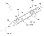
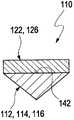
所述插入辅助装置包括至少一个基本上呈刚性的、用来导入到身体组织之中的基体。该基本上刚性的基体可以具有例如针形状,也就是纵向伸长的形状,其纵向延伸长度明显超过该刚性的基体的横向尺寸,例如超过10倍,最好至少超过100倍或更多。最好将该刚性的基体设计成单件构造,但原则上也可以将其设计成多部分的构造。所述刚性的基体可以正如在下面还要详细地阐述的那样,最好具有至少一个可以用来将插入辅助装置置入到身体组织之中的导入尖端。该导入尖端例如可以刺穿受检人员的皮肤表面和/或身体组织。可以将该导入尖端构造成例如被研磨的、锐边的导入尖端或者也可以是圆形的导入尖端。特别最好是非创伤性的导入尖端。所谓的“基本上刚性的基体”在这种情况下指的是这样的物体或者通常的元件:该物体或者元件通常在插入过程中所出现的力的作用下不会改变或者仅仅略微改变其外部形状。刚性的基体应该尤其在自身重力的作用下不会改变或者仅仅略微改变其形状。相应于此,例如可以用一种刚性的材料制成所述刚性的基体,最好使用一种生物相容性的材料,例如一种金属材料,优选的是不锈钢,和/或陶瓷材料和/或一种刚性塑料。也可以将不同的材料组合起来。以下也将该刚性的基体称作插入针,并且不限制其它可能的实施方式。The insertion aid comprises at least one substantially rigid base body for introduction into body tissue. The substantially rigid base can have, for example, a needle shape, ie a longitudinally elongated shape, whose longitudinal extension exceeds the transverse dimension of the rigid base significantly, eg by more than 10 times, preferably by at least 100 times or more. The rigid basic body is preferably designed as a one-piece construction, but in principle it is also possible to design it as a multi-part construction. The rigid base body can, as will be explained in more detail below, preferably have at least one introduction tip that can be used to insert the insertion aid into body tissue. The introduction tip can, for example, pierce the skin surface and/or body tissue of the person under examination. The introduction tip can be designed, for example, as a ground, sharp-edged introduction tip or also as a rounded introduction tip. Particularly preferred are atraumatic introduction tips. By "essentially rigid substrate" is meant in this case an object or generally element which normally does not change or only slightly changes its outer shape under the force occurring during insertion. shape. A rigid base body should in particular not change its shape or only slightly change its shape under the action of its own weight. Correspondingly, for example, the rigid base can be made of a rigid material, preferably a biocompatible material, such as a metallic material, preferably stainless steel, and/or a ceramic material and/or or a rigid plastic. Combinations of different materials are also possible. This rigid base body is also referred to below as an insertion needle, without limiting other possible embodiments.
所述插入装置可用用来在插入辅助装置的基体和皮下装置之间、例如在插入针和皮下传感器之间产生一种可变化的夹持力。所谓“可变化的夹持力”在此可以理解为:作用于皮下装置和基体之间的、并且其数值和/或其方向可以改变的作用力。尤其可以通过插入装置本身使其改变。所述夹持力尤其可以具有垂直于在基体和皮下装置之间的连线的分力。例如所述基体和皮下装置可以至少部分地具有一种长形形状,该长形形状具有例如平行的布置的纵向延伸轴线。在这种情况下,可变的夹持力可以具有例如垂直于这些纵向延伸轴线的分力。The insertion device can be used to generate a variable clamping force between the base body of the insertion aid and the subcutaneous device, for example between the insertion needle and the subcutaneous sensor. The so-called "variable clamping force" can be understood here as: a force acting between the subcutaneous device and the main body and whose magnitude and/or direction can be changed. In particular, it can be changed by inserting the device itself. In particular, the clamping force can have a force component perpendicular to the line between the main body and the subcutaneous device. For example, the base body and the subcutaneous device may at least partially have an elongated shape with, for example, parallel arranged longitudinal extension axes. In this case, the variable clamping force can have, for example, force components perpendicular to the axes of longitudinal extension.
所述插入装置可用来在导入过程中以及在导入之后调整出不同的夹持力。该插入装置如此进行设置:在导入过程中如此来调整所述夹持力,使得将皮下装置固定在基体上。插入装置还用来在导入之后如此调整夹持力,使得皮下装置可以与基体脱离。例如可通过该插入装置自动地从在导入过程中起作用的至少一个第一夹持力切换到至少一个与第一夹持力不同的并且在导入之后起作用的第二夹持力。为此目的,该插入装置例如可以具有控制器,该控制器可以例如连续地、逐步地或者分阶段地从第一夹持力切换到第二夹持力。控制器可以包括例如电子控制器和/或通过数据处理装置进行控制,并且可以例如将其完全地或者部分地集成在插入辅助装置和/或插入装置的另一部分之中。例如可以将该控制器容纳于插入装置的可重新使用(reusable)的部件之中,而与此相反,所述经皮装置则可以完全地或者部分地被例如设计成一次性(disposable)的部件,或者可以包括至少一个这种类型的一次性部件。然而所述经皮装置也可以包括一个或多个可以重新使用的部件。作为实现从第一夹持力切换到第二夹持力的替代或附加方案,也可以例如通过用户来触发从第一夹持力到第二夹持力的更换,例如通过操作至少一个操动元件,例如操作一种触发按钮,和/或通过简单地从身体组织中将插入辅助装置抽出。The insertion device can be used to set different clamping forces during and after the introduction. The insertion device is configured such that the clamping force is adjusted during the insertion process in such a way that the subcutaneous device is secured to the main body. The insertion device is also used to adjust the clamping force after insertion in such a way that the subcutaneous device can be detached from the basic body. For example, the insertion device can automatically switch from at least one first clamping force acting during the insertion process to at least one second clamping force different from the first clamping force and acting after the insertion. For this purpose, the insertion device can have, for example, a controller which can switch from the first clamping force to the second clamping force, for example continuously, gradually or in stages. The controller can comprise, for example, an electronic controller and/or be controlled by a data processing device and can, for example, be fully or partially integrated in the insertion aid and/or another part of the insertion device. For example, the controller can be housed in a reusable part of the insertion device, whereas the transcutaneous device can be completely or partially designed, for example, as a disposable part , or may include at least one disposable component of this type. However, the transcutaneous device may also comprise one or more reusable components. As an alternative or in addition to realizing the switchover from the first clamping force to the second clamping force, the changeover from the first clamping force to the second clamping force can also be triggered, for example by the user, for example by operating at least one actuation elements, for example by operating a trigger button, and/or by simply withdrawing the insertion aid from the body tissue.
所谓的“与基体脱离”在此可以理解为一种状态:其中夹持力不再或者仅仅在很小程度上将皮下装置固定在基体上。为此目的,例如可以如此地设计所述夹持力的大小和/或方向,使得例如通过身体组织上的摩擦力就能够轻易地克服该夹持力,从而当从身体组织中抽出所述插入辅助装置时,使得皮下装置至少部分地留在身体组织之中。可替代地是,可以将夹持力完全地设为零。还可替代地是,也可以如此设计所述夹持力,使得皮下装置从基体排斥开。The term "detachment from the basic body" is here understood to be a state in which the clamping force no longer or only slightly secures the subcutaneous device to the basic body. For this purpose, for example, the magnitude and/or direction of the clamping force can be designed in such a way that it can be easily overcome, for example, by friction on the body tissue, so that when the insertion force is withdrawn from the body tissue When assisting the device, the subcutaneous device is at least partially retained in the body tissue. Alternatively, the clamping force can be set entirely to zero. Alternatively, the clamping force can also be designed in such a way that the subcutaneous device is repelled from the basic body.
尤其可以如此地设置所述夹持力的大小和/或方向,使其在导入过程中至少在很大程度上在插入方向上阻止皮下装置和基体之间的空间上的移位。如果例如在导入过程中使得基体和皮下装置或者皮下装置的已被引入的部分基本上相互平行地定向,例如使其纵向延伸轴线以不大于10°的角度、优选是不大于5°的角度相互偏离,那么就例如可以在导入过程中如此地形成夹持力,使其至少阻止基体和皮下装置在平行于其纵向延伸轴线的方向上相互相对的在空间上的移位。因此所推荐的插入装置有别于例如在WO 03/080169中所公开的还能够平行于纵向延伸轴线移动的夹钳。此外这些夹钳在导入过程中以及在导入之后没有两种不同的夹持力。In particular, the clamping force can be dimensioned and/or directed in such a way that a spatial displacement between the subcutaneous device and the main body is prevented at least largely in the direction of insertion during the insertion process. If, for example, the base body and the subcutaneous device or the introduced part of the subcutaneous device are oriented substantially parallel to each other during the introduction, for example with their longitudinal extension axes at an angle of not more than 10°, preferably at an angle of not more than 5°, to each other Deviation, then, for example, the clamping force can be formed during the introduction process in such a way that it at least prevents a spatial displacement of the base body and the subcutaneous device relative to each other in a direction parallel to their longitudinal extension axis. The proposed insertion device thus differs from the clamps, which are also movable parallel to the axis of longitudinal extension, as disclosed, for example, in WO 03/080169. Furthermore, these clamps do not have two different clamping forces during insertion and after insertion.
在导入过程中和导入之后可以连续地或者也可例如分阶段地或者间歇地变换、即改变所述夹持力。在导入过程的不同阶段以及在导入之后也可以采用两种以上不同的夹持力。夹持力在这种情况下不必在方向上单调地变化,而是也可以例如包括非单调的变化。夹持力尤其可以包括非机械的夹持力,即不包括例如通过形状配合连接或者传力连接所引起的夹持力。原则上由现有技术可知不同的可行性方案用来产生这种可变化的夹持力,而且也可将其应用于所述当前的插入装置的范围之中,也可以应用在原则上任意的组合方式之中。During and after introduction, the clamping force can be changed, ie varied, continuously or also, for example, in stages or intermittently. It is also possible to use more than two different clamping forces at different stages of the introduction process and after introduction. In this case, the clamping force does not have to change monotonically in direction, but can also include non-monotonic changes, for example. In particular, the clamping force can comprise a non-mechanical clamping force, ie not include a clamping force caused, for example, by a form-fit connection or a non-positive connection. In principle, different possibilities are known from the prior art for generating such a variable clamping force and can also be used within the scope of the present insertion device, also in principle for any in combination.
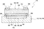
按照本发明的第一种实施方式,所述夹持力包括一种静电夹持力。例如很容易利用可以对其施加相应的电位的两个或多个电极来产生并且改变所述类型的静电夹持力。与此相应地,仅需改变这些电极的一个或多个电位,即可调整或改变所述夹持力。与此相应地,例如基体可以具有至少一个第一电极,其中皮下装置则具有至少一个第二电极。原则上也可以采用具有多于一个第一电极和/或具有多于一个第二电极的实施方式。可以将第一电极和/或第二电极作为在基体或者皮下装置中的独立的电极,但也可以将其设计成大面积的,并且例如构成所述基体或者皮下装置的较大的部件。尤其可以例如将整个基体作为第一电极,例如将其完全地设计成可以对其施加适当电位的金属基体。通常可以将插入装置用来给第一电极和第二电极施加不同的电位。与此相应地在第一电极和第二电极之间形成了至少一种电位差,也就是形成了一种电压。由于该电位差,在第一电极和第二电极之间作用一种静电力,该静电力在基体和皮下装置之间产生吸引力,或者在基体和皮下装置之间产生排斥力。例如可以通过电极几何形状和/或必要时通过在两个电极之间存在的材料和/或通过电位差来引起并且可以合适地改变所述静电力的大小和方向。插入装置可以具有例如至少一个电压源,该电压源可以生成不同的电位,或者在第一电极和第二电极之间生成电位差。可以例如改变该电位差的大小和/或方向,已便产生不同的夹持力。According to a first embodiment of the invention, the clamping force comprises an electrostatic clamping force. An electrostatic clamping force of the type described is easily produced and varied, for example, with two or more electrodes to which corresponding potentials can be applied. Correspondingly, the clamping force can be adjusted or changed only by changing one or more potentials of these electrodes. Accordingly, for example, the base body can have at least one first electrode, wherein the subcutaneous device then has at least one second electrode. In principle, embodiments with more than one first electrode and/or with more than one second electrode are also possible. The first electrode and/or the second electrode can be provided as separate electrodes in the main body or the subcutaneous device, but can also be designed over a large area and form, for example, a larger part of the main body or the subcutaneous device. In particular, it is possible, for example, to use the entire base body as the first electrode, for example, to design it completely as a metal base body to which a suitable potential can be applied. An intervening device can generally be used to apply different potentials to the first electrode and the second electrode. Correspondingly, at least one potential difference, ie a voltage, is formed between the first electrode and the second electrode. Due to this potential difference, an electrostatic force acts between the first electrode and the second electrode, which produces an attractive force between the base body and the subcutaneous device or a repulsive force between the base body and the subcutaneous device. The magnitude and direction of the electrostatic force can be induced, for example, by the electrode geometry and/or optionally by the material present between the two electrodes and/or by a potential difference, and can be suitably changed. The insertion device can have, for example, at least one voltage source which can generate different potentials or a potential difference between the first electrode and the second electrode. For example, the magnitude and/or direction of the potential difference can be changed to generate different clamping forces.
在这种情况下,原则上可以将一个或多个绝缘体布置在第一电极和第二电极之间。所述至少一个绝缘体例如可通过其介电常数来影响所述夹持力,并且可以包括例如至少一种介电材料。所述至少一个绝缘体可以是例如插入辅助装置的组成部分,和/或也可以是皮下装置的组成部分。例如所述至少一个绝缘体可以包括至少一个陶瓷的绝缘体和/或至少一个塑料绝缘体。例如可以利用所述至少一个绝缘体来防止在第一电极和第二电极之间可能会导致短路的直接接触。此外还可以通过所述至少一个绝缘体来影响所述夹持力的大小和/或方向。In this case, one or more insulators can in principle be arranged between the first electrode and the second electrode. The at least one insulator may influence the clamping force, for example via its dielectric constant, and may comprise, for example, at least one dielectric material. The at least one insulator can be, for example, a component of the insertion aid and/or also a component of the subcutaneous device. For example, the at least one insulator can comprise at least one ceramic insulator and/or at least one plastic insulator. For example, the at least one insulator can be used to prevent direct contact between the first electrode and the second electrode, which could lead to a short circuit. Furthermore, the magnitude and/or direction of the clamping force can also be influenced by the at least one insulating body.
按照本发明的一种优选的实施方式,可以通过至少另一个绝缘体完全地或部分地遮盖所述电极中的至少一个电极,也就是遮盖所述第一电极和/或第二电极。例如在将插入装置和/或皮下装置装入到身体组织中时处在身体组织之内的第一电极和/或第二电极的至少一个区域可以完全地或者部分地被所述至少另一个绝缘体所遮盖。特别优选的是,通过所述至少另一个绝缘体完全地或者部分地遮盖所述至少一个第一电极。该至少一个第一电极尤其可以通过所述至少另一个绝缘体相对于身体组织(例如间质)进行屏蔽和/隔离,例如进行电屏蔽和/或隔离。所述至少另一个绝缘体可以包括例如一个或多个绝缘层,例如一个或多个有机的和/或无机的绝缘层。所述至少另一个绝缘体也可以完全地或者部分地与通过其介电常数来影响所述夹持力的上述绝缘体合并在一起。所述至少另一个绝缘体可以例如完全地或部分地遮盖所述插入针,最好至少在将该插入针植入到身体组织之中的区域内遮盖插入针。如果皮下传感器(正如以下还将详细说明的那样)具有载体、尤其是柔性的载体,则载体的厚度最好明显地超过所述另一个绝缘体的厚度,例如至少超过2倍,最好至少超过5倍,并且特别是最好至少超过10倍。According to a preferred embodiment of the invention, at least one of the electrodes, ie the first electrode and/or the second electrode, can be completely or partially covered by at least one further insulator. For example, at least one region of the first electrode and/or the second electrode which is within the body tissue when the insertion device and/or the subcutaneous device is inserted into the body tissue can be completely or partially covered by the at least one other insulator covered. Particularly preferably, the at least one first electrode is completely or partially covered by the at least one further insulator. In particular, the at least one first electrode may be shielded and/or isolated, eg electrically shielded and/or isolated, from body tissue (eg interstitium) by the at least one further insulator. The at least one further insulator may comprise eg one or more insulating layers, eg one or more organic and/or inorganic insulating layers. The at least one further insulator can also be completely or partially integrated with the above-mentioned insulator whose dielectric constant influences the clamping force. The at least one further insulator can, for example, completely or partially cover the insertion needle, preferably at least in the region where the insertion needle is implanted in the body tissue. If the subcutaneous sensor (as will be explained in detail below) has a carrier, especially a flexible carrier, the thickness of the carrier is preferably significantly greater than the thickness of the other insulator, for example at least 2 times, preferably at least 5 times. times, and especially preferably at least more than 10 times.
作为利用一种静电夹持力的替代或附加方案,该夹持力原则上也可以包括磁性的夹持力。例如可以使用至少一个永久磁体和/或至少一个电磁铁或者组合运用所述类型的磁铁,来产生这种磁性的夹持力,来将其作为可变的夹持力。例如由磁性开关就已知这种可变化的磁性的夹持力。例如在电磁铁中通过改变电流就能改变磁性的夹持力,这例如通过改变电流方向和/或改变电流大小来实现。作为替代或附加方案,例如在永久磁体中,则尤其可通过所述至少一个永久磁体的机械位移来改变所述磁性的夹持力。这些原理由现有技术在原则上以磁性开关的形式已知,并且在该原理中利用永久磁体来执行开关动作。可想而知,也可以将一个或多个永久磁体与一个或多个电磁铁组合起来。尤其优选的是,由于简单的控制,就可使用至少一个电磁的夹持元件。相应于此,所述插入辅助装置和/或皮下装置可以包括至少一个用来产生磁场的电磁的夹持元件。例如该电磁的夹持元件可以包括至少一个导体线路环和/或线圈。在这种情况下,例如可以将该电磁的夹持元件布置在插入辅助装置之上或之中,作为替代或附加方案,也可以将其布置在皮下装置之中或之上。如果这两种元件中只有一种元件(即要么是插入辅助装置或者是皮下装置)配有用来产生磁场的电磁的夹持元件,则另一种元件(即皮下装置或者插入辅助装置)分别可以包括相应的对应元件,例如同样也可包括磁性的夹持元件(例如永久磁体的夹持元件和/或电磁的夹持元件)或者包括无源元件,例如可以与电磁的夹持元件相互作用的软磁元件和/或铁磁元件。如果最好在插入辅助装置中采用至少一个电磁的夹持元件,则插入装置可以具有例如至少一个用来产生可变电流的电流源,可以将该可变电流馈入到所述至少一个电磁的夹持元件之中。例如可以将该电流源设计成可变的电流源,从而可以调整电流的大小和/或方向。As an alternative or in addition to using an electrostatic holding force, the holding force can in principle also include a magnetic holding force. For example, at least one permanent magnet and/or at least one electromagnet or a combination of magnets of the stated type can be used to generate such a magnetic clamping force as a variable clamping force. Such variable magnetic holding forces are known, for example, from magnetic switches. For example, in electromagnets, the magnetic clamping force can be changed by changing the current, for example by changing the direction and/or changing the magnitude of the current. As an alternative or in addition, for example in the case of permanent magnets, the magnetic holding force can then be varied, in particular by a mechanical displacement of the at least one permanent magnet. These principles are known in principle from the prior art in the form of magnetic switches, in which permanent magnets are used to carry out the switching action. It is also conceivable to combine one or more permanent magnets with one or more electromagnets. It is especially preferred that at least one electromagnetic clamping element can be used due to the simple control. Accordingly, the insertion aid and/or the subcutaneous device can comprise at least one electromagnetic clamping element for generating a magnetic field. For example, the electromagnetic clamping element can comprise at least one conductor loop and/or coil. In this case, for example, the electromagnetic clamping element can be arranged on or in the insertion aid, as an alternative or in addition, it can also be arranged in or on the subcutaneous device. If only one of the two elements (i.e. either the insertion aid or the subcutaneous device) is equipped with an electromagnetic holding element for generating a magnetic field, the other element (i.e. the subcutaneous device or the insertion aid) respectively can comprise corresponding corresponding elements, for example also magnetic clamping elements (for example permanent magnet clamping elements and/or electromagnetic clamping elements) or passive elements, for example which can interact with electromagnetic clamping elements Soft magnetic elements and/or ferromagnetic elements. If preferably at least one electromagnetic clamping element is used in the insertion aid, the insertion device can have, for example, at least one current source for generating a variable current, which can be fed into the at least one electromagnetic clamping element. in the holding element. For example, the current source can be designed as a variable current source, so that the magnitude and/or direction of the current can be adjusted.
作为上述用来产生可变的夹持力的静电原理和/或磁性原理的替代或附加方案,还可以使用其它的用来产生可变的夹持力的原理。例如可以又通过电场和/或以其它电的和/或磁性的途径有目的地影响在基体与皮下装置之间的附着力。所述插入装置尤其可以用来影响所述插入辅助装置和/或皮下装置的至少一个附着面范围内的电荷载流子密度和/或电导率。所谓的“附着面”在这里可以理解为所述插入辅助装置和/或皮下装置的表面,该表面总是与另一个元件相邻,例如通过使得所述皮下装置贴靠在插入辅助装置的附着面上,反之亦可。附着面可以因此是插入辅助装置的组成部分或者是皮下装置的组成部分。可替换的是,插入辅助装置和皮下装置可以具有这种类型的附着面。例如在皮下装置和插入辅助装置之间可以存在至少一种附着力,该附着力例如通过粘附材料(例如粘合剂和/或其它材料,例如粘附性的有机材料)得以促进和/或引起。此外在这里作为所述材料的替代或附加方案示例性地提及,还可以将例如糖溶液和/或盐溶液形式的糖或盐作为粘附材料,例如在插入过程中可在其周围环境的水含量变化时例如自动溶解这些材料。在这些情况或者其它情况下,可以通过影响在所述插入辅助装置和/或皮下装置的所述至少一个附着面范围内的电荷载流子密度和/或电导率,就能有目的地影响在所述皮下装置与插入辅助装置之间的附着力。例如可以在利用场效应时做到这一点。可以利用场效应(例如在一种场效应晶体管中所利用的场效应),例如通过在至少一个电极(例如开关电极或者所谓的栅电极(Gate-Elektrode))上的电压变化来影响所述至少一个附着面范围内的载流子密度和/或电导率。所述至少一个附着面可以相应于此具有例如一种半导体材料,例如一种有机的和/或无机的半导体材料。相应于此,例如至少可以在附着面的范围内使用在有机的场效应晶体管中能够利用的材料。这可以是例如导电的或半导电的有机材料,尤其是共轭聚合物,或者其它的共轭有机材料,即具有共轭π-电子体系的材料。这种类型的有机的导电的或半导电的材料例如有聚乙炔、聚苯胺、聚噻吩、聚对苯撑或者其它具有扩展π-电子体系的有机材料。相应于此,所述至少一个附着面可以包括至少一个场效应晶体管,例如MOSFET,例如有机的场效应晶体管,其中该场效应晶体管的半导体材料各自指向另一个元件。如果附着面例如是所述插入辅助装置的组成部分,则半导体材料应指向皮下装置或者其对应的附着面。如果场效应晶体管是皮下装置的组成部分,那么其半导体材料应指向所述插入辅助装置。也可以将多个场效应晶体管组合起来。As an alternative or in addition to the electrostatic and/or magnetic principles described above for generating a variable holding force, other principles for generating a variable holding force can also be used. For example, the adhesive force between the main body and the subcutaneous device can be influenced in a targeted manner by means of an electric field and/or by other electrical and/or magnetic means. In particular, the insertion device can be used to influence the charge carrier density and/or the electrical conductivity in the area of at least one attachment surface of the insertion aid and/or the subcutaneous device. A so-called "attachment surface" is to be understood here as a surface of the insertion aid and/or of the subcutaneous device which is always adjacent to another element, for example by means of an attachment which brings the subcutaneous device against the insertion aid. On the surface, the opposite is also possible. The attachment surface can thus be a component of the insertion aid or a component of the subcutaneous device. Alternatively, the insertion aid and the subcutaneous device can have this type of attachment surface. For example, there may be at least one adhesion force between the subcutaneous device and the insertion aid, which adhesion force is facilitated, for example, by an adhesive material (such as an adhesive and/or other material, such as an adhesive organic material) and/or cause. Furthermore, sugar or salt, for example in the form of a sugar solution and/or a saline solution, can also be used as an adhesive material as an alternative or in addition to the material mentioned here, for example in its surroundings during insertion. These materials, for example, dissolve automatically when the water content changes. In these or other cases, by influencing the charge carrier density and/or conductivity in the range of the at least one attachment surface of the insertion aid and/or subcutaneous device, the Adhesion between the subcutaneous device and insertion aid. This can be done, for example, by utilizing field effects. Field effects, such as are used in a field effect transistor, can be used to influence the at least The carrier density and/or conductivity within an attachment surface. The at least one adhesion surface can accordingly have, for example, a semiconductor material, for example an organic and/or inorganic semiconductor material. Accordingly, materials that can be used in organic field-effect transistors can be used, for example, at least in the region of the attachment surface. These can be, for example, conductive or semiconductive organic materials, especially conjugated polymers, or other conjugated organic materials, ie materials with a conjugated π-electron system. Organic conductive or semiconductive materials of this type are, for example, polyacetylene, polyaniline, polythiophene, polyparaphenylene or other organic materials with an extended π-electron system. Accordingly, the at least one attachment surface can comprise at least one field-effect transistor, for example a MOSFET, for example an organic field-effect transistor, wherein the semiconductor material of the field-effect transistor is each directed towards the other component. If the attachment surface is, for example, a component part of the insertion aid, the semiconducting material should be directed towards the subcutaneous device or its corresponding attachment surface. If a field-effect transistor is a component of a subcutaneous device, its semiconductor material should be directed towards the insertion aid. It is also possible to combine multiple field effect transistors.
上述用来产生可变化的夹持力的示例也可以组合地使用,且该示例仅仅是如何能产生且能改变一种这样的可变的夹持力的可用示例。在原则上由现有技术已知不同的其它的可行方案,以便在插入辅助装置和皮下装置之间产生一种力,该力最好是非机械的,而且最好非接触地起到作用,并且该力是可以改变的。The above examples for producing a variable clamping force may also be used in combination, and this example is only one useful example of how one such variable clamping force can be produced and varied. In principle, various other possibilities are known from the prior art in order to generate a force between the insertion aid and the subcutaneous device, which preferably acts non-mechanically and preferably without contact, and This force can be changed.
所述插入辅助装置尤其可以具有用来在导入过程中放置皮下装置的支承面。该支承面可以包括或者构成例如所述插入辅助装置的上述至少一个可选的附着面。尤其可以将支承面设计成基本上平坦的支承面,例如区别于用来导入皮下传感器的已知的空心针。尤其可以如此设计所述插入辅助装置,使其并不包围所述皮下传感器,从而在没有垂直于所述插入辅助装置纵向延伸方向的夹持力的情况下可以与插入辅助装置无关地移去该皮下装置。In particular, the insertion aid can have a support surface for placing the subcutaneous device during the insertion procedure. This bearing surface can comprise or constitute, for example, the above-mentioned at least one optional attachment surface of the insertion aid. In particular, the bearing surface can be designed as a substantially flat bearing surface, for example in contrast to known hollow needles for introducing subcutaneous sensors. In particular, the insertion aid can be designed in such a way that it does not surround the subcutaneous sensor, so that it can be removed independently of the insertion aid without a clamping force perpendicular to the longitudinal extension of the insertion aid. Subcutaneous device.
所述插入辅助装置可以在对置于支承面的一侧具有一种轮廓,尤其是以下轮廓当中的某一种:多边形轮廓、尤其是三角形轮廓或者梯形轮廓;圆形轮廓、尤其是圆弧形轮廓。例如上述类型的轮廓形状可以提高所述插入辅助装置在导入到身体组织之中时的稳定性,尤其是当其至少部分地被设计成插入针的时候。同时可以减小穿刺腔道的轮廓,并且可以减小疼痛感。插入针例如可以具有至少一个导入尖端。所谓“导入尖端”在这种情况下可以理解成锐边的或者尖锐的元件,其中不仅可以使用磨锐的尖端,而且也可以使用具有圆形横断面的尖端,尤其是非创伤性的导入尖端。特别有利的是,插入辅助装置在导入尖端的范围内具有至少一个隆起部,其中该隆起部在导入时至少部分地遮盖所述皮下装置,从而在导入所述插入辅助装置与皮下装置时至少可减小作用于皮下装置上的力。该隆起部在指向皮下装置的一侧可以具有斜坡,从而当从身体组织中移去所述插入辅助装置时更加容易地从该插入辅助装置中移去皮下装置,例如使其滑过所述的斜坡。例如该隆起部可以直接地或者通过斜坡邻接所述支承面,例如基本上平坦的支承面,该支承面可以包含否则例如是圆形的插入针中的整平部分。The insertion aid can have a contour on the side opposite the support surface, in particular one of the following contours: a polygonal contour, in particular a triangular contour or a trapezoidal contour; a circular contour, in particular a circular arc contour. A contour shape of the above-mentioned type, for example, can increase the stability of the insertion aid when it is introduced into body tissue, in particular when it is designed at least partially as an insertion needle. At the same time, the contour of the puncture cavity can be reduced, and the pain can be reduced. The insertion needle can have at least one introduction tip, for example. An “introduction tip” in this case is to be understood as a sharp-edged or pointed element, wherein not only sharpened tips but also tips with a round cross-section can be used, in particular atraumatic introduction tips. It is particularly advantageous if the insertion aid has at least one bulge in the region of the insertion tip, wherein the bulge at least partially covers the subcutaneous device during insertion, so that at least the insertion aid and the subcutaneous device can be introduced. Reduces the forces acting on the subcutaneous device. The bulge can have a ramp on the side directed towards the subcutaneous device, so that when removing the insertion aid from the body tissue it is easier to remove the subcutaneous device from the insertion aid, for example by sliding it over the slope. For example, the elevation may adjoin the bearing surface, eg a substantially flat bearing surface, directly or via a ramp, which may comprise an otherwise eg circular flattened portion inserted into the needle.
如上所述,插入装置也包括至少一个皮下装置和至少一个插入辅助装置,其中可在这两个元件之间产生一种可变化的夹持力。除了一种或多种上述实施方式的插入装置之外,因此还推荐一种插入辅助装置和一种皮下装置,尤其可将其用于根据一种或多种上述实施方式的插入装置之中。与此相应地,至少在很大程度上可以参考以上的说明部分。尤其是只要实现上述产生可变的夹持力的原理,那么原则上也可以将所述插入辅助装置和皮下装置用于其它的插入装置之中。As mentioned above, the insertion device also comprises at least one subcutaneous device and at least one insertion aid, wherein a variable clamping force can be generated between these two elements. In addition to the insertion device according to one or more of the above-mentioned embodiments, an insertion aid and a subcutaneous device are therefore proposed, which can be used in particular in an insertion device according to one or more of the above-mentioned embodiments. Accordingly, reference is made, at least to a large extent, to the above description. In particular, the insertion aid and the subcutaneous device can also be used in other insertion devices in principle, as long as the above-mentioned principle of generating a variable clamping force is realized.
如上所述,所推荐的插入辅助装置可用于将皮下装置至少部分地插入到身体组织之中。插入辅助装置具有至少一个基本上呈刚性的、用于导入到身体组织之中的基体,尤其是具有至少一个插入针。例如可以将该插入针设计成实心针,也就是没有空腔。插入针可以包括例如整平部分,用于产生根据以上所述的支承面。插入辅助装置可以如此设置,以便与皮下装置如此地相互作用,从而可在基体和皮下装置之间产生可变的夹持力。为了这种目的,插入辅助装置可以包括例如至少一个第一夹持元件。相应于此,皮下装置可以包括例如至少一个第二夹持元件,和/或可设计用来以其它方式与该第一夹持元件相互作用。如上所述,插入辅助装置的该至少一个第一夹持元件例如可以是静电的夹持元件和/或磁性的夹持元件,尤其是电磁的夹持元件,和/或是以插入辅助装置的附着面范围内的载流子密度和/或电导率的变化为基础的第一夹持元件。也可以组合起来。对于其它实施方式,可参阅以上说明部分。例如可以通过在所述插入辅助装置中的相应引线将夹持元件与控制器连接起来,从而可以有目的地改变所述夹持力。对于其它可用的实施方式,可以参阅以上说明部分,在那里尤其可以参阅涉及到所述插入辅助装置的特征。As mentioned above, the proposed insertion aid can be used to at least partially insert a subcutaneous device into body tissue. The insertion aid has at least one substantially rigid main body for introduction into body tissue, in particular at least one insertion needle. For example, the insertion needle can be designed as a solid needle, ie without a cavity. The insertion needle may comprise, for example, a flattened portion for creating a bearing surface according to the above. The insertion aid can be arranged such that it interacts with the subcutaneous device in such a way that a variable clamping force can be produced between the main body and the subcutaneous device. For this purpose, the insertion aid can comprise, for example, at least one first clamping element. Accordingly, the subcutaneous device can comprise, for example, at least one second clamping element and/or can be designed to interact with the first clamping element in another way. As mentioned above, the at least one first clamping element of the insertion aid can be, for example, an electrostatic clamping element and/or a magnetic clamping element, in particular an electromagnetic clamping element, and/or can be a clamping element of the insertion aid. The first clamping element is based on a change in charge carrier density and/or conductivity in the area of the attachment surface. Can also be combined. For other implementations, reference may be made to the description above. For example, the clamping element can be connected to a controller via corresponding leads in the insertion aid, so that the clamping force can be varied in a targeted manner. For other possible embodiments, reference is made to the above description, where in particular reference is made to the features relating to the insertion aid.
所推荐的皮下装置适合于插入到身体组织之中,其中可以将皮下装置完全地或者部分地导入到身体组织之中,例如以经皮的方式。皮下装置尤其可以具有可以植入的部分和不可植入的部分。尤其可以将该皮下装置全部地或者部分地设计成皮下传感器,或者包括一种皮下传感器,尤其是用来检测例如在身体组织中的和/或在体液中的至少一种分析物的皮下传感器。如上所述,然而也可以采用皮下装置的其它实施方式,例如这样一种实施方式:其中传感器检测受检人员的至少另一种物理和/或化学特性,和/或这样一种实施方式:其中皮下装置包括至少一个治疗装置和/或至少一个用来作用于身体组织和/或受检人员的执行器。如上所述,该皮下装置可以包括至少一个可以植入的部分。最好将该可植入的部分设计成完全地或者部分地柔性的形式,使其在身体组织内部作常规运动时可以变形。相应于此,皮下传感器可以例如具有载体,尤其是柔性载体,例如条形的柔性载体和/或管状的柔性载体。例如该载体可以包括作为柔性材料的塑料材料和/或一种纸质材料和/或一种陶瓷材料,其中也可以采用层压材料。所述载体可以容纳一个或多个功能元件。例如如上所述,可以将皮下传感器的一个或多个检测区和/或电极容纳于载体上和/或容纳于载体之中,例如用来以电化学和/或光学方式检测在体液或者身体组织中的所述至少一种分析物。就此而言,可以参考诊断技术领域中的常见的检测元件,该检测元件例如可以用来检测体液中至少一种分析物,并且可参考以上引用的现有技术。皮下装置还可以包括例如一个或多个导线,该导线例如可以经由载体导向身体组织之外的某一区域之中,以便在那里例如与控制器相连。例如可以将载体构造成一次性单元(disposable),并且例如将其与多次使用的单元(reusable)相连。The proposed subcutaneous device is suitable for insertion into body tissue, wherein the subcutaneous device can be introduced completely or partially into body tissue, for example percutaneously. In particular, a subcutaneous device can have an implantable part and a non-implantable part. In particular, the subcutaneous device can be designed wholly or partially as a subcutaneous sensor, or comprise a subcutaneous sensor, in particular for detecting at least one analyte, for example in body tissue and/or in a body fluid. As mentioned above, however, other embodiments of the subcutaneous device may also be used, such as an embodiment in which the sensor detects at least another physical and/or chemical characteristic of the subject, and/or an embodiment in which The subcutaneous device includes at least one treatment device and/or at least one actuator for acting on body tissue and/or a person under examination. As noted above, the subcutaneous device may include at least one implantable portion. Preferably the implantable part is designed to be fully or partially flexible so that it can deform during routine movements within body tissue. Accordingly, the subcutaneous sensor can have, for example, a carrier, in particular a flexible carrier, for example a strip-shaped flexible carrier and/or a tubular flexible carrier. For example, the carrier can comprise a plastic material and/or a paper material and/or a ceramic material as flexible material, wherein laminated materials can also be used. The carrier may house one or more functional elements. For example, as described above, one or more detection regions and/or electrodes of a subcutaneous sensor can be accommodated on and/or in a carrier, for example for electrochemically and/or optically detecting The at least one analyte in. In this regard, reference is made to conventional detection elements from the field of diagnostic technology, which can be used, for example, to detect at least one analyte in body fluids, and reference is made to the above-cited prior art. The subcutaneous device can also comprise, for example, one or more wires, which can be guided, for example via a carrier, into an area outside the body tissue, in order to be connected there, for example, to a controller. For example, the carrier can be configured as a disposable unit (disposable) and connected to it, for example, with a reusable unit (reusable).
尤其可以将皮下装置用于上述一种或多种实施方式中的一种插入装置之中。相应于此,该皮下装置可用来与导入到身体组织之中的插入辅助装置的基体如此相互作用,从而能够在基体和皮下装置之间产生一种可变的夹持力。所述基体例如可以是插入辅助装置的以上所述的、基本上刚性地构造的基体。如上所述,皮下装置为了所述目的可以例如在可以植入的部分中包括至少一个第二夹持元件,该夹持元件可以与插入辅助装置的基体如此相互作用,从而可以产生可变的夹持力。例如该第二夹持元件可以与所述插入辅助装置的第一夹持元件和/或插入辅助装置的整个基体相互作用。如上所述,第二夹持元件例如基于静电原理、磁性原理、尤其是电磁原理,和/或基于在皮下装置的至少一个附着面范围内改变载流子密度和/或电导率的原理。例如该附着面可以是皮下装置的在插入过程中贴靠在插入辅助装置的上述支承面上的表面。作为替代或附加方案,也可以采用其它的用来产生可变夹持力的作用原理。In particular a subcutaneous device may be used in one of the insertion devices in one or more of the embodiments described above. Accordingly, the subcutaneous device can be used to interact with the base body of an insertion aid introduced into body tissue in such a way that a variable clamping force can be generated between the base body and the subcutaneous device. The main body can be, for example, the above-described substantially rigid main body of the insertion aid. As already mentioned above, the subcutaneous device can for this purpose comprise at least one second clamping element, for example in the implantable part, which can interact with the basic body of the insertion aid in such a way that a variable clamping element can be produced. holding power. For example, the second clamping element can interact with the first clamping element of the insertion aid and/or with the entire main body of the insertion aid. As mentioned above, the second clamping element is based, for example, on electrostatic, magnetic, in particular electromagnetic principles and/or on a change in charge carrier density and/or electrical conductivity in the area of at least one attachment surface of the subcutaneous device. For example, the attachment surface can be a surface of the subcutaneous device which bears against the above-mentioned bearing surface of the insertion aid during the insertion process. As an alternative or in addition, other principles of action for generating a variable clamping force can also be used.
与所述类型的已知装置相比,根据本发明的插入装置、插入辅助装置和皮下装置具有许多优点。例如可以用这种方式实现可以控制的插入针,可将其用来有目的地并且可靠地植入一种皮下装置,例如一种传感器。在此可以将插入针和传感器物理连接起来,用于插入例如一种连续测量的传感器。如上所述,可以使用不同的物理机制,例如静电荷,该静电荷通过将电场连接到插入针和传感器上而产生,或者利用磁性,或者有目的地改变附着面的附着特性。后者可以按照以上所述的那样,例如采用施加电场的方式来实现,该电场使得感应式的有机的聚合物如此取向,使得该聚合物的在界面上的附着特性发生变化,和/或使得附着面上的载流子密度和/或电导率发生变化。上述原理或者其它原理具有的共性在于:通过改变由插入针和传感器或者插入辅助装置和皮下装置所构成的复合物的物理特性,就能有目的地改变这两种物体的附着性。因此本发明的构思与现有技术的区别就在于:其中使用了基本上呈刚性的、或者其自身特性可以缓慢变化的插入辅助装置。本发明的构思与上述WO 03/080169的区别在于:可以有目的地改变夹持力,并且例如在导入过程中也可以对皮下装置施加一种夹持力,该夹持力可以沿着插入方向、也就是平行于插入辅助装置和/或皮下装置的纵向延伸轴线地发挥作用。例如用这种方式也可以在植入过程中在所述插入辅助装置上或者之中移动皮下装置,或者防止该皮下装置折弯。The insertion device, insertion aid and subcutaneous device according to the invention have a number of advantages compared to known devices of said type. For example, a controllable insertion needle can be realized in this way, which can be used to implant a subcutaneous device, for example a sensor, in a targeted and reliable manner. In this case, an insertion needle and a sensor can be physically connected for inserting, for example, a continuous measuring sensor. As mentioned above, different physical mechanisms can be used, such as electrostatic charge, which is generated by connecting an electric field to the insertion needle and sensor, or using magnetism, or purposefully changing the adhesion properties of the attachment surface. The latter can be achieved as described above, for example, by applying an electric field that orients the inductive organic polymer in such a way that the adhesion properties of the polymer at the interface change, and/or such that The carrier density and/or conductivity on the attachment surface changes. The above principles or other principles have in common that by changing the physical properties of the complex consisting of the insertion needle and the sensor or the insertion aid and the subcutaneous device, the adhesion of the two objects can be purposefully altered. The concept of the present invention thus differs from the prior art in that an insertion aid is used which is essentially rigid or whose own properties can be changed slowly. The concept of the present invention differs from the aforementioned WO 03/080169 in that the clamping force can be purposefully varied and, for example, can also be applied to the subcutaneous device during introduction with a clamping force that can be directed along the direction of insertion. , that is to say act parallel to the axis of longitudinal extension of the insertion aid and/or the subcutaneous device. In this way, for example, the subcutaneous device can also be displaced on or in the insertion aid during the implantation process or be prevented from buckling.
利用所述的插入装置、插入辅助装置和/或皮下装置尤其可以用微创方式将一种柔性的皮下传感器或者另一种皮下装置如此地施加到身体组织之中,例如置入到皮肤之中,使得穿刺轮廓最小地构成。为此可以使得皮下装置和/或其可以植入的部分在导入(插入)过程中变硬。当移去插入辅助装置时,皮下装置可以保持其按照规定的形状不变。因此可以在一定的时刻使得皮下装置在移去插入辅助装置时留在组织之中,也以可控的方式来完成。尤其可以通过“解脱机构”来设定一种被限定的时刻,在该时刻使得皮下装置如此脱离所述插入辅助装置:例如通过有目的地影响所述可变化的夹持力。In particular, with the described insertion device, insertion aid and/or subcutaneous device, a flexible subcutaneous sensor or another subcutaneous device can be applied in a minimally invasive manner into body tissue, for example into the skin , so that the puncture profile is minimally formed. To this end, the subcutaneous device and/or its implantable part can be stiffened during the introduction (insertion) process. When the insertion aid is removed, the subcutaneous device can retain its prescribed shape. It is thus possible to cause the subcutaneous device to remain in the tissue at a certain point in time when the insertion aid is removed, also in a controlled manner. In particular, a defined moment at which the subcutaneous device is disengaged from the insertion aid can be set by means of the "release mechanism", for example by purposefully influencing the variable clamping force.
尤其可以对此进行如此设计:使得可在插入过程中、例如在穿刺过程中,使得通过插入辅助装置可在时间上受限制地支持皮下装置,该皮下装置如上所述最好完全地或者部分地柔性地构造,例如构造为柔性的传感器。这例如通过有目的地影响夹持力的控制器能够以控制方式来实现。插入辅助装置可以具有例如在轮廓方面与皮下装置或者其可以植入的部分(例如传感器)类似的、支持该皮下装置的扁平结构。这样,所述皮下装置(例如柔性的传感器)就不会因为插入力而偏离其直线的插入运动。在这种情况下,柔性的皮下装置可以紧贴在刚性的、在轮廓方面与传感器相类似的、扁平的插入针上。例如可以如同以上所述的那样,这种贴靠通过一个或多个可变的夹持力来产生-例如通过静电的、电磁的或者可控的附着力或粘合力来产生。在此,所述“附着力”和“粘合力”的概念在当前的范围内基本上是同义词。也可以将所述的夹持力和/或其它可变的夹持力组合起来。在插入装置和皮下装置之间的受控制的贴靠尤其可以导致:在插入过程中使得皮下装置(例如传感器)在插入辅助装置(例如插入针)上的夹持力超过由皮肤或身体组织作用于皮下装置上的推力。如果皮下装置(例如传感器)已到达终点位置,就可以有目的地改变所述夹持力,例如有目的地将其切断或者甚至使其反转(以致例如实现排斥开),从而当从身体组织中移去插入辅助装置时使得皮下装置留在终点位置之中,也就是留在至少已部分地植入的位置之中。例如可以通过以下方式做到这一点:减小在皮下装置和插入辅助装置之间的摩擦,和/或将皮下装置从插入辅助装置上排斥开,从而很容易地从身体组织中抽出所述插入辅助装置,并且不会抽出皮下装置。In particular, it can be designed such that a subcutaneous device, which as described above is preferably fully or partially Flexible, eg as a flexible sensor. This can be achieved in a controlled manner, for example, by a controller that influences the clamping force in a targeted manner. The insertion aid can have a flat structure that supports the subcutaneous device, for example similar in contour to the subcutaneous device or its implantable part (eg sensor). In this way, the subcutaneous device (for example a flexible sensor) cannot deviate from its linear insertion movement due to the insertion force. In this case, the flexible subcutaneous device can rest on a rigid, flat insertion needle similar in contour to the sensor. For example, as described above, this contact can be produced by one or more variable clamping forces—for example, by electrostatic, electromagnetic or controllable adhesion or adhesive forces. In this context, the terms "adhesion" and "adhesion" are essentially synonymous in the present context. Combinations of the described clamping forces and/or other variable clamping forces are also possible. The controlled abutment between the insertion device and the subcutaneous device can in particular lead to a clamping force of the subcutaneous device (such as a sensor) on an insertion aid (such as an insertion needle) that exceeds that exerted by the skin or body tissue during insertion. Push force on subcutaneous device. If the subcutaneous device (such as a sensor) has reached the end position, the clamping force can be purposefully changed, for example purposefully cut off or even reversed (so that, for example, repulsion is achieved), so that when the When removing the insertion aid, the subcutaneous device remains in the end position, ie in the at least partially implanted position. This can be done, for example, by reducing the friction between the subcutaneous device and the insertion aid, and/or repelling the subcutaneous device from the insertion aid so that the insertion can be easily withdrawn from the body tissue. assist device, and does not withdraw the subcutaneous device.
插入辅助装置、尤其是插入针应该最好仅仅具有皮下装置的宽度、尤其是皮下装置(例如传感器)的可植入部分的宽度,并且可以相应于此将其设计得比较薄。以这种方式就能保证穿刺轮廓独自地仅仅最低程度地大于传感器轮廓,且在任何情况下均小于空心针。相应于此,最好使得插入辅助装置、尤其是插入针垂直于插入方向地具有一种最大的延伸长度,它不超过皮下装置的可植入部分的最大延伸长度,或者仅仅略微超过、例如超过最多50%,最好超过最多20%,特别最好超过最多10%。这可以例如由此来保证:可植入的装置(例如柔性的传感器)至少在宽度范围内、也就是垂直于插入方向地完全地遮盖所述支承面。但是原则上也可将皮下装置设计成完全地或者部分地有基底的形式,例如在垂直于插入方向的剖面中具有倒圆的、弯角的或者弯曲的轮廓。但优先选用一种在该剖面中基本上平坦的实施方式。The insertion aid, in particular the insertion needle, should preferably only have the width of the subcutaneous device, in particular the width of the implantable part of the subcutaneous device (eg sensor), and can be designed relatively thin accordingly. In this way it is ensured that the piercing contour alone is only minimally larger than the sensor contour and in any case smaller than the hollow needle. Correspondingly, preferably the insertion aid, in particular the insertion needle, has a maximum extension perpendicular to the insertion direction which does not exceed the maximum extension of the implantable part of the subcutaneous device or only slightly exceeds, for example exceeds A maximum of 50%, preferably a maximum of 20%, particularly preferably a maximum of 10%. This can be ensured, for example, that the implantable device (for example a flexible sensor) completely covers the support surface at least in its width, ie perpendicularly to the insertion direction. In principle, however, the subcutaneous device can also be designed completely or partially with a base, for example with a rounded, angled or curved contour in a section perpendicular to the insertion direction. However, preference is given to an embodiment which is essentially planar in this section.
按照以上所述,通过对于附着面范围内的载流子密度和/或电导率进行的影响,就可有目的地影响该附着面的附着特性,这就开辟了新的应用可能性,尤其是在使用有机的半导电的和/或导电的材料的情况下,例如在使用共轭聚合物或者具有共轭π-电子体系的低分子有机物质时。因此例如可以低成本地生产和使用聚合物电子材料,即使在大规模的批量工艺的情况下也是如此。以这种方式就能以低廉的成本灵活地生产例如皮下装置、尤其是可以植入的传感器。例如可以针对新的特殊的特性,优化和开发聚合物电子材料。因此例如可想而知的是,可通过施加电压的方式有目的地改变聚合物的取向,从而有目的地改变其局部载流子密度和/或其载流子密度或者电导率。这样就能以有目的地控制附着力的方式来调整附着特性。According to the above, by influencing the charge carrier density and/or the electrical conductivity in the area of the attachment surface, the adhesion properties of this adhesion surface can be influenced in a targeted manner, which opens up new application possibilities, in particular When using organic semiconducting and/or conducting materials, for example when using conjugated polymers or low-molecular organic substances with conjugated π-electron systems. Thus, for example, polymer electronic materials can be produced and used cost-effectively, even in the case of large-scale batch processes. In this way, for example subcutaneous devices, in particular implantable sensors, can be produced flexibly and cost-effectively. For example, polymer electronic materials can be optimized and developed for new special properties. It is therefore conceivable, for example, to selectively change the orientation of the polymer and thus its local charge carrier density and/or its charge charge density or electrical conductivity by applying an electrical voltage. This makes it possible to adjust the adhesion properties in such a way that the adhesion force can be controlled in a targeted manner.
附图简要说明Brief description of the drawings
关于本发明的其它细节和特征,可从下面对于优选实施例的描述而得出,尤其是结合从属权利要求。在此可以单独地实现相应的特征,或者将多个特征相互组合起来而实现。本发明并不限于这些实施例。该实施例在附图中示意性地示出。各个附图中相同的附图标记在此均表示相同或者功能相同或者说在其功能方面相互对应的元件。Further details and features of the invention can be derived from the following description of preferred embodiments, especially in conjunction with the dependent claims. Corresponding features can be implemented individually or in combination with one another. The present invention is not limited to these examples. This embodiment is shown schematically in the drawing. Identical reference signs in the various figures designate identical or functionally identical elements or corresponding to one another in terms of their function.
具体示出:Specifically show:
附图1A和1B具有静电的夹持力的插入装置的第一种实施例的不同示意图;Accompanying drawing 1A and 1B have the different schematic diagrams of the first embodiment of the insertion device of electrostatic clamping force;
附图2A和2B具有磁性的夹持力的插入装置的第二种实施例的不同视图;2A and 2B are different views of a second embodiment of an insertion device with magnetic clamping force;
附图3A至3C插入装置的不同轮廓;Figures 3A to 3C show different profiles of insertion devices;
附图4具有隆起导入尖端的插入装置;以及Accompanying drawing 4 has the insertion device of protruding introduction tip; And
附图5通过有机电子结构产生可变夹持力的插入装置的实施例。Figure 5 shows an embodiment of an insertion device that generates variable clamping force through an organic electronic structure.
具体实施例specific embodiment
在附图1A和1B中以不同的示意图示出了根据本发明的插入装置110的第一种实施例。在这里,附图1A示出了平行于用″x″所标记的穿刺路径的剖面中的剖视图,而附图1B示出了插入装置110的俯视图。A first exemplary embodiment of an
插入装置110包括插入辅助装置112与基本上呈刚性的基体114。这里将基体114设计成例如实心针形式的插入针116,例如用钢制成的实心针。插入针116具有导入尖端118,它在图中示例性地示为圆尖端。但原则上也可以采用其它实施方式,例如附图3A至4所示的实施方式。将插入针116设计成基本上在穿刺路径x的方向上延伸的、纵向伸展的、具有纵向延伸轴线120的、刚性的基体114。The
此外所述插入装置110还具有可利用插入装置110将其插入到身体组织124之中的皮下装置122。在附图1A中仅仅象征性地表示出所述身体组织。该皮下装置122在附图所示的实施例中示例性地被设计成皮下传感器126,它可用来检测身体组织124中的至少一种分析物或者身体组织124中的一种体液。但也可以正如以上所述的那样,采用其它的实施方式。皮下传感器126具有载体128,在附图所示的实施例中,将三个传感器电极130示例性地布置在所述载体上,使得这些传感器电极130指向身体组织124。传感器电极130在这种情况下例如可以呈圆形,其中也可以采用其它几何形状,例如椭圆形或者多边形的几何形状。也可以采用其它数量的传感器电极。例如传感器电极130可以包括至少一个工作电极、至少一个对应电极和至少一个参比电极,以便以电化学方式检测身体组织124中的至少一种分析物和/或一种体液。也可以将所述至少一个对应电极和所述至少一个参比电极完全地或部分地合并成一个共同的电极。传感器电极130除了包括例如金属电极之外,还可以包括例如一种或多种氧化还原系统和/或酶。原则上在现有技术条件下以电化学方式检测分析物的领域中就已知这种类型的传感器电极130。Furthermore, the
载体128可以是例如柔性的,并且可以包括例如一种多层结构。例如载体128可以完全地或者部分地由一种塑料材料和/或纸质材料和/或陶瓷材料和/或层压材料制成,并且也可沿着纵向延伸轴线132延伸,该纵向延伸轴线132例如在插入过程中正如附图1A所示的那样,平行于纵向延伸轴线120。在这种情况下,将皮下装置122部分地插入到身体组织124之中,包括可植入的部分134和没有植入的部分136。在没有植入的部分136的范围内,皮下装置122可以具有例如尤其在附图1B中所看出的支架138。可以利用该支架138将皮下装置122例如固定住,和/或在使用之后将其从身体组织124中向外抽出。在没有植入的部分136的范围内,皮下装置122可以包括例如传感器触点140,例如每个传感器电极130的各一个传感器触点140。这些传感器触点140例如可以通过在附图1A和1B中没有绘出的电极引线、例如在载体128的层状结构之内与传感器电极130相连接,从而可以与传感器电极130实现电接触或者截取其电位。The
基本上呈条形的、柔性的皮下传感器126在附图1A和1B所示的实施例中平坦地贴靠在所述插入辅助装置112的支承面142上。但原则上也可以采用其它的实施方式。In the exemplary embodiment shown in FIGS. 1A and 1B , substantially strip-shaped, flexible subcutaneous sensor 126 rests flat against
按照附图所示的实施例的插入装置110的发明思想就在于:在所述插入辅助装置112和皮下装置122之间产生可变化的夹持力。为了实现这一目的,在附图所示的实施例中的插入装置110具有控制器144,该控制器可以是例如所述插入辅助装置112的组成部分,和/或可以将其布置在外部,例如布置在插入装置110的可以重新使用的部分之中。插入针116在该实施例中是金属的,并且总体上作为第一电极146,因此也作为第一夹持元件148。皮下装置122本身具有第二电极150作为第二夹持元件152。例如可以将金属的涂覆物和/或柔性的铜镀层形式的第二电极150涂覆到载体128上,和/或集成到载体128之中。也可以采用不同的实施方式。例如插入针116也可以完全地或者部分地涂上具有导电特性的有机聚合物来替代使用金属,从而形成第一电极146。可以想到的是,在皮下装置122中也可以使用有机的导电材料来作为第二电极150的材料。The inventive concept of the
插入辅助装置112和/或皮下装置122的材料最好地完全地或者部分地可以消毒,例如利用辐射进行消毒,尤其是以下一种或多种辐射:紫外辐射、X射线辐射、伽玛辐射、电子辐射。The material of the insertion aid 112 and/or the subcutaneous device 122 is preferably completely or partially sterilizable, for example by radiation, in particular one or more of the following: ultraviolet radiation, X-ray radiation, gamma radiation, Electron radiation.
插入装置110还具有至少一个布置在第一电极146和第二电极150之间的绝缘体154。例如该绝缘体154可以完全地或者部分地是插入辅助装置112的组成部分,和/或完全地或部分地是皮下装置122的组成部分。为了避免在组织中短路,插入针116和/或皮下装置122周围尤其可以具有绝缘体154,例如相应的涂层。The
第一电极146和第二电极150可以在插入过程中与控制器144相连接。为了实现这一目的,例如在附图1B中可以看出,皮下装置122可以包括例如场板触点156,可以通过该场板触点在控制器144与例如设计成场板(Feldplatte)的第二电极150之间形成一种相应的连接。相应地,也可以将插入辅助装置112、尤其是插入针116与控制器144相连接。该连接可以是永久的,但也可以在完成插入之后完全地或部分地分开。The first electrode 146 and the second electrode 150 may be connected to the
如附图1A所示的那样,控制器144最好地包括一切换装置158,可将其用来改变第一电极146和第二电极150之间的电位差,从而可以改变皮下装置122和插入辅助装置112之间的静电夹持力。在附图所示实施例中,所述切换装置158可用来有选择地将第一电极146和第二电极150经由电压源160或者短路连接机构162相互连接起来。也可以采用其它的实施方式改变在第一电极146和第二电极150之间的电位差。在按照附图1A所示的实施例中,图中以S1标记的开关位置可在皮下装置122和插入辅助装置112之间产生一种起到吸引作用的夹持力,而与此相反,切换装置158的用虚线表示的开关位置S2产生的夹持力为0,或者甚至在插入针116和皮下装置122之间产生排斥力。电压源160尤其可以包括直流电压源。在开关位置S1中因此起作用的是静电吸引力。最好在穿刺过程中保持施加所述电压。在从身体组织124中抽出插入针116之前,切断所述电压源160,或者说使得切换装置158进入到开关位置S2之中。例如这样就会使得电极146、150短路。在这种情况下不再有夹持力起作用,或者电极146、150因为电位相同而相互排斥。如此减小静摩擦,使得克服身体组织124的压紧力而很容易抽出插入针116。例如可以利用可选择地也能提供电接触的、并且在附图1B中以附图标记164表示的相应的穿刺装置和/或拔出装置来执行该操作。As shown in FIG. 1A, the
以下将阐述作用于插入装置110之上的力关系。在附图1A中部分地绘出了这些力。其中FG表示由所述组织对于插入装置110所施加的力,FH表示通过电场所引起的夹持力,FE表示插入过程中的穿刺力,FF表示插入过程中正面的、作用于皮下装置122上的力。The force relationships acting on the
在两个理想的板状的电极146、150之间的静电力关系式如下:The electrostatic force relationship between two ideal plate-shaped electrodes 146, 150 is as follows:
式中ε0表示介电常数,其值为8.85*10-12As/Vm;εr表示通常介于4至80之间的无量纲的相对介电常数;A表示电极146和150的有效的电极面积,例如可以在5和50mm2之间,尤其为20mm2;a表示在所述电极146、150之间的距离,例如可以在10μm至100μm之间,尤其为50μm;U表示在电极146、150之间的电压,例如可以在1至100V之间,尤其为10伏特。在所述的这些值中,若面积A为20mm2,距离a为50μm,电压为10V,则夹持力大约为0.3mN,因此比较小。为了提高该夹持力FH,适合提高所述电压U和/或减小所述距离a。In the formula, ε0 represents the dielectric constant, and its value is 8.85*10−12 As/Vm; εr represents the dimensionless relative permittivity usually between 4 and 80; A represents the effective of the electrodes 146 and 150 The electrode area, for example, can be between 5 and 50 mm2 , especially 20 mm2 ; a indicates the distance between the electrodes 146 and 150 , for example, it can be between 10 μm and 100 μm, especially 50 μm; U indicates the distance between the electrodes 146 , 150, for example, can be between 1 and 100V, especially 10 volts. Among the stated values, if the area A is 20 mm2 , the distance a is 50 μm, and the voltage is 10 V, the clamping force is about 0.3 mN, which is relatively small. In order to increase the clamping force FH , it is expedient to increase the voltage U and/or reduce the distance a.
若要将插入装置110、尤其是插入针116和皮下传感器126刺入,必须使用以下穿刺力FE:To penetrate the
FE=μ1,2*FG+μ3,4*FG+FF (2).FE =μ1,2 *FG +μ3,4 *FG +FF (2).
该关系式(2)仅仅简化地考虑了滑动摩擦和静止状态。式中μ1,2和μ3,4表示了在皮下装置122与组织124之间的滑动摩擦系数(μ1,2)或者在插入辅助装置112与组织124之间的滑动摩擦系数(μ3,4)。This relation (2) only considers the sliding friction and the stationary state for simplicity. where μ1,2 and μ3,4 represent the coefficient of sliding friction between subcutaneous device 122 and tissue 124 (μ1,2 ) or the coefficient of sliding friction between insertion aid 112 and tissue 124 (μ3 , 4 ).
为了使皮下装置122在插入过程中附着在所述插入辅助装置112上,必须满足以下条件:In order for the subcutaneous device 122 to attach to the insertion aid 112 during insertion, the following conditions must be met:
(μ1,2*FG+FF)<<μ2,3*FH (3)(μ1,2 *FG +FF )<<μ2,3 *FH (3)
式中μ2,3表示在皮下装置122与插入辅助装置112之间的摩擦系数,将其乘以夹持力FH,即表征出所述皮下装置122在插入辅助装置112上的摩擦力,该摩擦力在穿刺过程中防止皮下装置122在插入辅助装置112上滑动。如果满足上述关系式(3),并且插入针116的刚度充分,那么所述插入装置110就会在插入过程中保持伸展状态。例如若将黄铜放在木材组织上,且中间有一层水膜,则典型的静摩擦系数μ1,2和/或μ3,4数量级为0.24。In the formula, μ2,3 represents the coefficient of friction between the subcutaneous device 122 and the insertion auxiliary device 112, which is multiplied by the clamping force FH , which characterizes the friction force of the subcutaneous device 122 on the insertion auxiliary device 112, This frictional force prevents the subcutaneous device 122 from sliding over the insertion aid 112 during piercing. If the above-mentioned relation (3) is satisfied, and the rigidity of the insertion needle 116 is sufficient, the
在附图1C中示出了在附图1A和1B中所示出的插入装置110的实施例的变型方案。该变型方案基本上首先相当于在附图1A和1B中所示出的实施例,因此可以参考以上关于该实施例的说明。但在附图所示的变型方案中,所述第一电极146附加地还可以完全地或者部分地被另一绝缘体165、例如绝缘层所遮盖。例如所述另一绝缘体165可以在下述区域内完全地或部分地遮盖第一电极146:该区域在植入状态下伸入到身体组织124、例如间质组纱之中。例如可以将所述另一绝缘体165设计成密闭地密封的电绝缘体。该另一绝缘体165也可以完全地或者部分地与(例如起到电介质作用的)绝缘体154合并成为例如插入针116的共同的绝缘涂层,或者完全地或部分地与该绝缘体154相同。A variant of the exemplary embodiment of the
该变型方案考虑到了这样的事实:如果第一电极146相对于身体组织124之间的绝缘缺失或者不够充分,第一电极146的电势可能会经由通常导电传导的身体组织124、例如间质组织抵达载体128的、例如载体膜的背面。这样就能通过起到电介质作用的绝缘体154削弱或者甚至抵消在第一电极146与第二电极150之间的电场和力的作用。可以通过形成第二个反向力场的方式做到这一点。可以通过使得第一电极146尤其是相对于身体组织124至少部分地进行绝缘来减小或者甚至避免这种效应。This variant takes into account the fact that if the insulation between the first electrode 146 with respect to the
在附图1C中以附图标记D1表示出所述载体128的、例如载体膜的厚度,与此相对地以附图标记D2表示所述另一绝缘体165的厚度。为了防止第一电极146的绝缘受损,载体128的厚度D1应当选择得明显大于所述另一绝缘体165的厚度D2。这样就能可靠地保证:大大地减小所形成的寄生电容(
在附图1A、1B和1C中的实施例示出了根据静电原理来产生可变化的夹持力,而在附图2A和2B中示出一种插入装置110的实施例,该实施例是以磁性地产生一种夹持力为基础的。在附图2A和2B中仅仅示意性地示出了所述产生,其中附图2A又示出了通过所述插入装置110平行于穿刺路径x的剖视图(类似于在附图1A中的视图),并且其中附图2B示出了垂直于在附图2A中的投影面的剖视图。The embodiment in accompanying drawing 1A, 1B and 1C has shown to produce variable clamping force according to electrostatic principle, and in accompanying drawing 2A and 2B, shows the embodiment of a kind of
所述插入装置110又包括一种插入辅助装置112,该插入辅助装置又可以具有插入针116形式的基体114。为此可以在很大程度上参阅以上对于附图1A和1B的说明。在本实施例中没有绘出导入尖端118,但是它同样可以存在。The
此外,所述插入装置110又包括皮下装置122,例如又可以将其设计成皮下传感器126,并且可将其植入到身体组织124之中。关于皮下传感器126的可用实施方式,例如可参阅以上对于附图1A和1B的说明。Furthermore, the
在本实施例中,插入辅助装置112又具有第一夹持元件148,并且相应地所述皮下装置122具有第二夹持元件152,用来在皮下装置122与插入辅助装置112之间产生可变化的夹持力。如上所示出的那样,夹持元件148、152应该产生一种夹持力FH,这种情况下可将其完全地或者部分地设计成磁性的夹持力FB。相应于此,可将所述夹持元件148、152设计成磁性的夹持元件,可以用不同的方式做到这一点,可使用永久磁体和/或使用电磁铁,也可以将其任意地组合起来。这在附图2A和2B中以一种方式来实现,其中第一夹持元件148包括永久磁体166,该永久磁体具有磁极168和对应磁极170。例如所述插入辅助装置112可以完全用一种可以磁化的材料或者相应地已被磁化的磁性材料来制成。作为替代或附加方案,第一夹持元件148也可以包括被嵌入到插入辅助装置112的载体材料之中的永久磁体或者多个这样的永久磁体和/或至少一个导磁的衔铁片(Ankerblech)。In the present exemplary embodiment, the insertion aid 112 again has a first clamping element 148 and correspondingly the subcutaneous device 122 has a second clamping element 152 for creating a secure connection between the subcutaneous device 122 and the insertion aid 112 . Varying gripping force. As indicated above, the clamping elements 148 , 152 are intended to generate a clamping force FH , which in this case can be designed completely or partially as a magnetic clamping force FB . Correspondingly, the clamping elements 148, 152 can be designed as magnetic clamping elements, which can be achieved in different ways, using permanent magnets and/or using electromagnets, which can also be combined as desired stand up. This is achieved in one way in FIGS. 2A and 2B , where the first clamping element 148 includes a permanent magnet 166 having a
在附图所示的实施例中,第二夹持元件152包括电磁的夹持元件172,该电磁的夹持元件在本实施例中包括单圈的导体线路环174,当然也可以采用更加复杂的结构。在附图2A中仅仅象征性地绘出了该导体线路环174,并且例如可以如在附图2B中所示的那样,将其涂覆在皮下装置122的载体128上,和/或安置于载体之中。例如载体128可以包括一种绝缘材料,例如一种塑料、纸、陶瓷或者层压材料。原则上也可以使用导电的材料。在附图2B中的剖视图里示出了流过导体线路环174的电流方向,其中所述电流在左侧的导体线路环段中流入到绘图平面之中,并且在右侧的导体线路环段中流出该绘图平面,但也可以采用其它的实施方式。可以通过控制器144给导体线路环通电,其中所述控制器144又可以包括例如电压源和/或电流源176,并且必要时也可包括一个或多个其它器件,例如电阻、电容、二极管或者也可以是有源的电子器件。也可以采用不同的实施方式。原则上,专业人士都知晓用于控制一种电磁的夹持元件172的控制器144的实施方式。In the embodiment shown in the drawings, the second clamping element 152 comprises an electromagnetic clamping element 172, which in this embodiment comprises a single-
控制器144可以用来有目的地调整或者影响所述流经导体线路环174的电流。在附图2A里所示出的控制器144的实施例中,可通过一种纯粹的数字的接通或关闭方式做到这一点。在此又可以设置一种切换装置158,以便从所述导体线路环174被通电的开关状态S1切换到该切换装置被158断开并且没有电流流过的开关状态S2。原则上也可以采用其它的实施方式。通常例如可以通过控制器144来影响所述电流流过导体线路环174的电流强度的数值和/或方向,从而可以与第一夹持元件148相互作用地在所述两个夹持元件148和152之间产生一种吸引力或者排斥力,或者使得力为0。例如可以形象地对此进行解释:永久磁体166产生附图2B中以附图标记204表示的磁力线。通过基材-衔铁片178将该磁力线缩短,从而产生夹持力。可以如此调整流过所述导体线路环174的电流,使得包围着该导体线路环174的磁力线206反作用于永久磁体166的磁场,或者指向相同方向,从而可以调节磁性的合力,并且例如可以实现排斥的作用。例如当插入装置110穿刺或者插入到身体组织124之中时,则可以调节起到吸引作用的夹持力;与此相反,当穿刺之后,则在皮下装置122和插入辅助装置112之间可以调节出为0的作用力或者甚至是排斥力,从而使得皮下装置122脱离所述插入辅助装置112。The
在附图2A和2B里所示的实施例中,在载体128下方将基材-衔铁片178示例性地布置在皮下装置122里的层状结构之中。该基材-衔铁片178可以例如用一种磁性材料(例如一种软磁材料)制成,或者可以包括这样的一种材料;在该基材-衔铁片下方可以有气隙180,可以通过至少一个绝缘体完全地或者部分地填充该气隙。可以用这种方式对于一种磁力FB产生影响。在此仅在根据附图2A的视图中绘出了所述气隙180,但原则上也可以在根据附图2B的视图中插入所述气隙。In the exemplary embodiment shown in FIGS. 2A and 2B , the base material-
若没有电流经过所述导体线路环174,那么第一夹持元件148的永久磁体166的磁力就会作用于第二夹持元件152的基材-衔铁片178上。可以例如如此地选择流过导体线路环174的电流方向,使得通过由导体线路环174所产生的磁场反作用于永久磁体166的磁场,来削弱所述磁性的夹持力。这样就能补偿、抵消或者甚至过度补偿所述夹持力。可以用这种方式,借助于控制器144来调整流过所述导体线路环174的电流强度,从而能够影响所述磁性的夹持力。If no current flows through the
应指出的是:附图所示的实施方式仅仅是如何使用磁性的夹持元件的众多可行方案中的一种。第一夹持元件148和/或第二夹持元件152通常可以包括一个或多个以下的磁性的夹持元件:电磁的夹持元件,例如导体线路环(Leiterbahnschleife);永久磁体;由磁性材料(例如软磁材料)制成的衔铁片。例如第一和第二夹持元件可以各自本身产生磁场,和/或仅仅这些夹持元件148、152之一可以产生分别能够吸引或排斥所述夹持元件148、152中的另一个夹持元件的磁场。可想而知有不同的组合可行方案。It should be pointed out that the embodiment shown in the figures is only one of many possible solutions how to use the magnetic clamping element. The first clamping element 148 and/or the second clamping element 152 can generally comprise one or more of the following magnetic clamping elements: electromagnetic clamping elements, for example conductor loops (Leiterbahnschleife); permanent magnets; made of magnetic material Armature pieces made of (such as soft magnetic materials). For example the first and second clamping elements may each themselves generate a magnetic field, and/or only one of the clamping elements 148, 152 may generate a magnetic field capable of attracting or repelling the other of said clamping elements 148, 152, respectively. magnetic field. It is conceivable that there are different combinations of feasible solutions.
在附图所示的实施例中,例如可以如上所述将插入针116完全地或者部分地设计成永久磁体或者永磁体166,例如通过将磁极168设计成北极,并且将对应磁极170设计成南极,或者反之亦可。皮下传感器126或皮下装置122可以至少部分地用一种导电材料制成。原则上也可以使用例如不锈钢,但是不很适用,因为不锈钢只有弱磁性。可以用这种方式构成基材-衔铁片178,该基材-衔铁片在磁极168、170的范围内构成衔铁。这样就能缩短磁力线,从而可在穿刺过程中产生夹持力。如果皮下传感器126或皮下装置122已经在场,则对于在皮下传感器126上往复延伸的导体线路环174施加例如一种电流脉冲。该电流脉冲现在可以产生一种与针中的静磁场作用相反、并且减小或者甚至抵消所述夹持力的力。现在可以从组织中抽出所述插入针116,而皮下传感器126则留在身体组织124之中。例如可以使得电流脉冲在其时间变化曲线和/或其形状方面与插入针116的拔出运动相同步,例如通过能检测和/或产生所述拔出运动的相应电子电路来进行所述同步。例如以这种方式能够实现一种时间最佳的力相互作用,并且能高效地使用所投入的能量。这尤其是在电池工作模式下特别有益,例如利用电池工作的插入装置110和/或插入辅助装置112,例如可重新使用的单元。由于可以主动进行控制,因此可在分离和抽出时实现时间最佳的力相互作用,从而也能更加有效地实现动态分离和/或脱离过程。以这种方式也能利用极短的电流脉冲产生很好的结果,这尤其对于下述可重新使用的单元而言很有好处:其中可供使用的能量通常是有限的。In the embodiment shown in the figures, for example, the insertion needle 116 can be completely or partially designed as a permanent magnet or permanent magnet 166 as described above, for example by designing the
与根据附图1A和1B所示的实施例相类似,至少又可以近似地计算所述力的关系。如果只有永久磁体166发挥作用,则在第一夹持元件148和第二夹持元件152之间作用如下的力:Similar to the exemplary embodiment according to FIGS. 1A and 1B , the force relationship can again be calculated at least approximately. If only the permanent magnet 166 is active, the following forces act between the first clamping element 148 and the second clamping element 152:
式中B表示永久磁体166的磁感应;A表示气隙180的面积;μ表示导磁率,根据μ=μ0*μr,该导磁率由真空的导磁率μ0与气隙180中材料的相对导磁率μr组成。In the formula, B represents the magnetic induction of the permanent magnet 166; A represents the area of the
永久磁体的力FB,P反作用于导体线路环174的磁力,以下将该磁力称作FB,L:The force FB,P of the permanent magnet acts against the magnetic force of the
式中1表示导体线路环174的长度;I表示流过导体线路环174的电流;μ又表示导磁率;h表示导体线路环174与磁性材料之间的距离,导体线路环174磁地作用于该磁性材料,例如作用于永久磁体166。以上公式(4)和(5)表示的力FB,P和FB,L相加得到总的磁性的夹持力In the formula, 1 represents the length of the
FB=FH=FB,P+FB,L (6)FB =FH =FB,P +FB,L (6)
相应地通过选择电流I的方向(即符号)和大小并且通过适当地选择材料,就能通过控制器144当前地来影响所述分别起作用的夹持力,从起到吸引作用的夹持力FH、经过所述夹持力FH=0、直至一种起到排斥作用的夹持力FH。Correspondingly by selecting the direction (i.e. sign) and magnitude of the current I and by selecting the material appropriately, the respectively acting clamping force can be influenced by the
在穿刺过程中,相应地又可满足的条件为:夹持力FH或者通过该夹持力所引起的静摩擦力必须大大超过插入过程中作用于皮下装置122上的合力,以使得皮下装置122在插入过程中不会弯曲,或者不会脱离所述插入辅助装置112。应相地应该使用上述公式(3),其中在这种情况下应将FH替换成在公式(6)中所表示的总的磁性的夹持力。During the puncture, the condition that can be satisfied correspondingly is: the clamping force FH or the static friction force caused by the clamping force must greatly exceed the resultant force acting on the subcutaneous device 122 during the insertion process, so that the subcutaneous device 122 There is no bending or detachment of the insertion aid 112 during insertion. Accordingly, the above formula (3) should be used, wherein in this case FH is to be replaced by the total magnetic holding force expressed in formula (6).
在附图1A至2B中的上述实施例中,假设所述皮下装置122至少部分地、尤其以其可以植入的部分134贴靠在插入辅助装置112的支承面142上。为此目的,可以将支承面142设计成例如整平的形状,例如作为插入针116一侧上的整平部分,该整平部分例如可以在插入针116的全长范围内延伸,或者仅仅在一部分长度范围内延伸。最好将该支承面142设计成平坦的形状。在尺寸设计方面,最好使得皮下装置122在其宽度上匹配于支承面142的宽度,使得穿刺到身体组织124之中的最大宽度不超过或者仅仅不显著地超过皮下装置122或者皮下装置122的可植入部分134的最大宽度。In the above-described exemplary embodiments in FIGS. 1A to 2B , it was assumed that the subcutaneous device 122 rests at least partially, in particular with its
如在附图3A至3C中所示出的那样,尤其可以在支承面142的范围内如此设计所述插入辅助装置112、特别是其基体114的轮廓形状,使得提高插入辅助装置112在插入时的稳定性。例如在附图3A中示出了一种三角形的轮廓,在附图3B中示出了一种梯形的轮廓,并且在附图3C中示出了一种圆弧形的轮廓,例如半圆形的轮廓。这样就能例如防止插入针116在插入过程中弯曲。As shown in FIGS. 3A to 3C , the contour shape of the insertion aid 112 , in particular of its base body 114 , can be designed in particular in the area of the
如上所述,插入辅助装置112、特别是其基体114或插入针116可以可选择地具有导入尖端118。这在附图4中象征性地示出。在此也示出了,在附图4中以D表示的导入尖端118的最大宽度超过以d表示的在支承面142范围内的基体114的最大宽度。因此所述导入尖端118至少部分地遮盖皮下装置122的端面182。可以通过这种特殊形状的“弯曲(Bug)”来减小在插入过程中作用于皮下装置122上的、正面的力FF(例如参见附图1A和2A)。支承面142同时可以在其朝向导入尖端118的一侧通入到斜坡184之中,在皮下装置122脱离插入辅助装置112之后,皮下装置122可以在该斜坡上滑动,从而保留在身体组织124之中,同时从身体组织124中抽出所述插入辅助装置112。原则上,可以将根据附图3A至3C的和/或根据附图4的所述实施方式与本说明书的任意其它实施例、例如与根据附图1A和1B、2A和2B或者5所示的实施方式组合起来。As mentioned above, the insertion aid 112 , in particular its base body 114 or the insertion needle 116 , can optionally have an
作为根据附图1A和1B的静电的夹持原理和/或根据附图2A和2B的磁性的夹持原理的替代方案或附加方案,也可以使用其它原理来产生可变的夹持力FH。在附图5中所示的实施方式为另一种原理。在该原理中,有目的地并且通过电作用来影响由附着面186所施加的附着力。As an alternative or in addition to the electrostatic clamping principle according to FIGS. 1A and 1B and/or the magnetic clamping principle according to FIGS. 2A and 2B , other principles can also be used to generate the variable clamping force FH . The embodiment shown in FIG. 5 is another principle. In this principle, the adhesive force exerted by the
因此附图5又示例性地示出了插入装置110,其中关于可能的实施方式,在很大程度上可参阅以上的说明。该插入装置又包括插入辅助装置112,例如具有插入针116形式的基体114,该插入针在这里仅仅示意性地示出。该插入装置具有支承面142,皮下装置122、例如皮下传感器126的载体128(传感器基体)通过附着力而贴靠在该支承面上。附着面186在本实施例中是皮下装置122的组成部分。但也可以采用其它的实施方式,即其中所述附着面186是插入辅助装置112的组成部分的实施方式,例如与支承面142相同,和/或不仅插入辅助装置112而且皮下装置122都配有相互作用的附着面186的实施方式。FIG. 5 therefore again shows an example of an
在附图所示的实施例中,载体128至少在附着面186的范围内具有一种导电的或者半导电的聚合物,这里以附图标记188表示该聚合物。这种导电的或半导电的聚合物例如可以完全地或者部分地是共轭聚合物,也就是其中双键和单键交替变化的聚合物。这样就会形成一种具有导电或半导电特性的扩展π-电子体系。可以将聚乙炔作为这种共轭聚合物的代表性物质。作为替代或附加方案,也可以使用其它的共轭聚合物和/或低聚物和/或优选同样具有扩展π-电子体系的较小分子,例如聚噻吩、聚对苯撑亚乙烯(Poly-paraphenylenvinylen)、聚对苯撑、并五苯、并四苯,或者对于有机电子领域中的专业人士来说是已知的其它类似的材料。In the exemplary embodiment shown in the figures, the
在所推荐的实施例中,插入装置110又具有控制器144,可以通过该控制器有目的地影响附着面186的附着特性。为此目的,可以有目的地影响附着面186的载流子密度和/或电导率。在本实施例中,可通过类似于有机的场效应晶体管的一种场效应来实现这一点。控制器144具有第一电压源190以及第二电压源192。第一电压源190给通过有机的、导电的或半导电的聚合物188连接起来的、相对置的电极194、196施加电压和/或电流,而第二电压源192给栅电极(Gate-Elektrode)198施加一种栅电压(Gate-Spannung)。可以在栅电极198与载体128之间插入绝缘物200。与此相应地可以影响所述栅电极198的电位,这又通过场效应来影响在附着面186范围内的载流子密度和/或载流子运动特性以及因此一种电导率。该电导率在另一方面又影响所述附着作用,也就是在插入辅助装置112和皮下装置122之间的夹持力。如上所述,尤其在大多数情况下,π-电子是决定电导率和/或载流子密度和/或运动特性的决定因素,因为聚合物188的π-桥可以提供运动的电荷。通过对于聚合物188进行适当改性,就能有目的地调整所述附着特性。在附着面186的范围内,还可以在插入辅助装置112和皮下装置122之间插入至少一种附着促进剂202,例如一种粘合剂。该附着促进剂在附图5中象征性地以附图标记202表示。例如可以将该附着促进剂202涂覆到支承面142上。例如可以通过改变附着面186的载流子密度和/电导率而有目的地影响该利用附着促进剂202实现的附着。In the preferred exemplary embodiment, the
通过影响在电压源190、192上的电压和/或由这些电压源190、192所提供的电流,就能有目的地影响附着特性并因此影响附着力。因此也可以利用控制器144有目的地影响在皮下装置122和插入辅助装置112之间的附着力。By influencing the voltage at the
用于提高在皮下装置122和插入辅助装置112之间的附着的另一种原理性的可行方案可以作为上述方法的替代的或附加的方案,该可行方案通过可控的外部的影响来影响插入装置100的部件的附着或者分离。例如可想而知,可通过有目的地力作用使得被伸展的、处在预紧力作用下的薄膜分开,例如通过作用于载体128的薄膜的外端上的力来实现,由此将该薄膜撕开或者分离。例如这样就能使得在插入辅助装置112和皮下装置122和/或皮下装置122的部件之间的附着得以骤然改变。As an alternative or in addition to the method described above, another basic possibility for improving the adhesion between the subcutaneous device 122 and the insertion aid 112 is possible, which influences the insertion by controllable external influences. Attachment or detachment of components of device 100 . It is conceivable, for example, that the stretched, pretensioned film can be separated by a purposeful force, for example by a force acting on the outer end of the film of the
附图标记列表List of reference signs
160 电压源160 voltage source
110 插入装置 30 162 短路连接机构110 Insertion device 30 162 Short-circuit connection mechanism
112 插入辅助装置 164 穿刺装置/拔出装置112 Insertion aids 164 Piercing/extracting devices
114 基体 165 另一绝缘体114
116 插入针 166 永久磁体116 Insertion pin 166 Permanent magnet
118 导入尖端 168 磁极118 lead-in
120 纵向延伸轴线 35 170 对应磁极120 Longitudinal extension axis 35 170 Corresponding magnetic poles
122 皮下装置 172 电磁的夹持元件122 Subcutaneous device 172 Electromagnetic gripping element
124 身体组织 174 导体线路环124
126 皮下传感器 176 电流源126
128 载体 178 基材-衔铁片
130 传感器电极 40 180 气隙130 sensor electrodes 40 180 air gap
132 纵向延伸轴线 182 端面132
134 可植入的部分 184 斜坡134
136 不可植入的部分 186 附着面136
138 支架 188 聚合物138
140 传感器触点 45 190 第一电压源140 sensor contact 45 190 first voltage source
142 支承面 192 第二电压源142
144 控制器 194 电极144
146 第一电极 196 电极146
148 第一夹持元件 198 栅电极148
150 第二电极 50 200 绝缘物150 Second Electrode 50 200 Insulator
152 第二夹持元件 202 附着促进剂152
154 绝缘体 204 磁力线(永久磁体)154
156 场板触点 206 磁力线(导体线路环)156
158 切换装置158 switching device
Claims (16)
Applications Claiming Priority (3)
| Application Number | Priority Date | Filing Date | Title |
|---|---|---|---|
| EP09160090AEP2250959A1 (en) | 2009-05-13 | 2009-05-13 | Controllable sensor insertion needle |
| EP09160090.8 | 2009-05-13 | ||
| PCT/EP2010/056421WO2010130715A1 (en) | 2009-05-13 | 2010-05-11 | Controllable sensor insertion needle |
Publications (2)
| Publication Number | Publication Date |
|---|---|
| CN102438508Atrue CN102438508A (en) | 2012-05-02 |
| CN102438508B CN102438508B (en) | 2014-10-29 |
Family
ID=40999961
Family Applications (1)
| Application Number | Title | Priority Date | Filing Date |
|---|---|---|---|
| CN201080021004.8AActiveCN102438508B (en) | 2009-05-13 | 2010-05-11 | Controllable sensor insertion needle |
Country Status (4)
| Country | Link |
|---|---|
| US (1) | US9662070B2 (en) |
| EP (2) | EP2250959A1 (en) |
| CN (1) | CN102438508B (en) |
| WO (1) | WO2010130715A1 (en) |
Cited By (3)
| Publication number | Priority date | Publication date | Assignee | Title |
|---|---|---|---|---|
| CN108903916A (en)* | 2018-07-31 | 2018-11-30 | 浙江大学 | The implant needle and method for implantation of flexible implanted biosensor and photoelectric device |
| CN113796972A (en)* | 2020-06-15 | 2021-12-17 | 西门子医疗有限公司 | Threading aid for threading objects into a guide device |
| WO2025050335A1 (en)* | 2023-09-07 | 2025-03-13 | 上海联影微电子科技有限公司 | Analyte sensor, and preparation method therefor and application method thereof |
Families Citing this family (13)
| Publication number | Priority date | Publication date | Assignee | Title |
|---|---|---|---|---|
| RU2705613C2 (en) | 2014-07-22 | 2019-11-11 | Ф. Хоффманн-Ля Рош Аг | Sensor insertion device equipped with safety device |
| RU2017101849A (en) | 2014-07-22 | 2018-08-22 | Ф.Хоффманн-Ля Рош Аг | DEVICE FOR INTRODUCING A SENSOR WITH PROTECTION AGAINST RE-USE |
| US10194842B2 (en) | 2014-09-03 | 2019-02-05 | Nova Biomedical Corporation | Subcutaneous sensor inserter and method |
| US20160166277A1 (en)* | 2014-12-15 | 2016-06-16 | Biotronik Se & Co. Kg | Implantation Kit and Method for Implantation of an Implantable Medical Device |
| WO2019005301A1 (en)* | 2017-06-30 | 2019-01-03 | Integrated Medical Sensors, Inc. | Wireless sensing platform for multi-analyte sensing |
| CN107688141B (en)* | 2017-10-20 | 2023-12-29 | 广东电网有限责任公司电力科学研究院 | Interface of composite insulator Performance test system and method |
| US12144614B2 (en)* | 2018-01-18 | 2024-11-19 | King Abdullah University Of Science And Technology | N-type polymer based electrochemical device for direct enzymatic metabolite sensing and methods of making and using |
| DE102018101275A1 (en) | 2018-01-22 | 2019-07-25 | Eyesense Gmbh | Injector for transcutaneously introducing a sensor into a patient |
| EP3545897A1 (en)* | 2018-03-29 | 2019-10-02 | Koninklijke Philips N.V. | An implantable device |
| CN114902039B (en) | 2019-08-03 | 2024-04-05 | 阿卜杜拉国王科技大学 | Device for detecting analytes in samples and methods of using the same |
| WO2021138067A1 (en)* | 2019-12-31 | 2021-07-08 | X Development Llc | Magnetoencephalography |
| US11786150B1 (en) | 2021-09-01 | 2023-10-17 | Integrated Medical Sensors, Inc. | Wired implantable monolithic integrated sensor circuit |
| CN115410780A (en)* | 2022-07-25 | 2022-11-29 | 中国电子科技集团公司第二十九研究所 | High-temperature-adaptability insulator and preparation device thereof |
Citations (4)
| Publication number | Priority date | Publication date | Assignee | Title |
|---|---|---|---|---|
| CN88101341A (en)* | 1987-02-10 | 1988-11-23 | 约翰·布鲁诺 | Container device for safe removal, storage and ultimate disposal of needles from hypodermic needle/syringe assemblies |
| CN2086142U (en)* | 1991-03-19 | 1991-10-09 | 吴冬青 | Automatic acupuncture and moxibustion injector |
| WO2003080169A1 (en)* | 2002-03-22 | 2003-10-02 | Novo Nordisk A/S | Atraumatic insertion of a subcutaneous device |
| US20070156126A1 (en)* | 2005-12-29 | 2007-07-05 | Flaherty J C | Medical device insertion system and related methods |
Family Cites Families (11)
| Publication number | Priority date | Publication date | Assignee | Title |
|---|---|---|---|---|
| US5390671A (en) | 1994-03-15 | 1995-02-21 | Minimed Inc. | Transcutaneous sensor insertion set |
| US6498870B1 (en)* | 1998-04-20 | 2002-12-24 | Omm, Inc. | Micromachined optomechanical switches |
| US6360888B1 (en)* | 1999-02-25 | 2002-03-26 | Minimed Inc. | Glucose sensor package system |
| US6229683B1 (en)* | 1999-06-30 | 2001-05-08 | Mcnc | High voltage micromachined electrostatic switch |
| US7003336B2 (en)* | 2000-02-10 | 2006-02-21 | Medtronic Minimed, Inc. | Analyte sensor method of making the same |
| DE10117286A1 (en) | 2001-04-06 | 2002-10-17 | Disetronic Licensing Ag | Soft cannula |
| DE10306013A1 (en) | 2003-01-17 | 2004-07-29 | Disetronic Licensing Ag | Simplified and improved temperature-sensitive cannula for e.g. longer-term infusion, softens following insertion at a critical temperature |
| JP4611278B2 (en) | 2003-01-17 | 2011-01-12 | ディセトロニック・ライセンシング・アクチェンゲゼルシャフト | Flexible needle |
| US7375404B2 (en)* | 2003-12-05 | 2008-05-20 | University Of Maryland Biotechnology Institute | Fabrication and integration of polymeric bioMEMS |
| DE102004002472B4 (en) | 2004-01-16 | 2007-09-13 | Disetronic Licensing Ag | needle |
| US7783333B2 (en) | 2004-07-13 | 2010-08-24 | Dexcom, Inc. | Transcutaneous medical device with variable stiffness |
- 2009
- 2009-05-13EPEP09160090Apatent/EP2250959A1/ennot_activeCeased
- 2010
- 2010-05-11EPEP10718601.7Apatent/EP2429382B1/enactiveActive
- 2010-05-11CNCN201080021004.8Apatent/CN102438508B/enactiveActive
- 2010-05-11WOPCT/EP2010/056421patent/WO2010130715A1/enactiveApplication Filing
- 2011
- 2011-11-11USUS13/294,643patent/US9662070B2/enactiveActive
Patent Citations (4)
| Publication number | Priority date | Publication date | Assignee | Title |
|---|---|---|---|---|
| CN88101341A (en)* | 1987-02-10 | 1988-11-23 | 约翰·布鲁诺 | Container device for safe removal, storage and ultimate disposal of needles from hypodermic needle/syringe assemblies |
| CN2086142U (en)* | 1991-03-19 | 1991-10-09 | 吴冬青 | Automatic acupuncture and moxibustion injector |
| WO2003080169A1 (en)* | 2002-03-22 | 2003-10-02 | Novo Nordisk A/S | Atraumatic insertion of a subcutaneous device |
| US20070156126A1 (en)* | 2005-12-29 | 2007-07-05 | Flaherty J C | Medical device insertion system and related methods |
Cited By (5)
| Publication number | Priority date | Publication date | Assignee | Title |
|---|---|---|---|---|
| CN108903916A (en)* | 2018-07-31 | 2018-11-30 | 浙江大学 | The implant needle and method for implantation of flexible implanted biosensor and photoelectric device |
| CN108903916B (en)* | 2018-07-31 | 2024-04-02 | 浙江大学 | Implantation needle and implantation method of flexible implantation type biosensor and photoelectric device |
| CN113796972A (en)* | 2020-06-15 | 2021-12-17 | 西门子医疗有限公司 | Threading aid for threading objects into a guide device |
| CN113796972B (en)* | 2020-06-15 | 2025-05-27 | 西门子医疗股份公司 | Insertion aid for inserting an object into a guide device |
| WO2025050335A1 (en)* | 2023-09-07 | 2025-03-13 | 上海联影微电子科技有限公司 | Analyte sensor, and preparation method therefor and application method thereof |
Also Published As
| Publication number | Publication date |
|---|---|
| EP2429382B1 (en) | 2013-08-14 |
| EP2250959A1 (en) | 2010-11-17 |
| CN102438508B (en) | 2014-10-29 |
| US20120078072A1 (en) | 2012-03-29 |
| HK1170138A1 (en) | 2013-02-22 |
| US9662070B2 (en) | 2017-05-30 |
| EP2429382A1 (en) | 2012-03-21 |
| WO2010130715A1 (en) | 2010-11-18 |
Similar Documents
| Publication | Publication Date | Title |
|---|---|---|
| CN102438508B (en) | Controllable sensor insertion needle | |
| US9931478B2 (en) | Needles system | |
| JP6926130B2 (en) | A medical device for percutaneously inserting an insertable element into living tissue | |
| Daugimont et al. | Hollow microneedle arrays for intradermal drug delivery and DNA electroporation | |
| Martanto et al. | Transdermal delivery of insulin using microneedles in vivo | |
| US7315758B2 (en) | Transdermal delivery of therapeutic agent | |
| CA2806765C (en) | Method and apparatus for insertion of a sensor | |
| WO2011077893A1 (en) | Measurement device and sensor placement method | |
| US9743862B2 (en) | Systems and methods for transcutaneously implanting medical devices | |
| WO2010093546A2 (en) | Iontophoretic system for transdermal delivery of active agents for therapeutic and medicinal purposes | |
| SG175341A1 (en) | Iontophoretic device with improved counterelectrode | |
| EP3706855B1 (en) | Apparatus for the transdermal delivery of active agents | |
| US20240033428A1 (en) | Pump-connectable analyte sensing cannula | |
| KR102357677B1 (en) | Microneedle apparatus for skin repair and method of manufacturing the same | |
| HK1170138B (en) | Controllable sensor insertion needle | |
| KR200402506Y1 (en) | Delivering lon to the body by using a needle | |
| KR102728069B1 (en) | Biodegradable metallic microneedle patch electrodes for enhanced transdermal drug delivery | |
| Knoll et al. | Minimally invasive suction sampling unit for interstitial fluid enhanced by electroosmotic mass transport | |
| JP2004033374A (en) | In vivo information detection unit | |
| AU2023417349A1 (en) | Devices and methods for sensing analytes and delivering therapeutic agents | |
| WO2020018696A1 (en) | Analyte sensor | |
| Kwiatkowski et al. | Transdermal delivery of therapeutic agent |
Legal Events
| Date | Code | Title | Description |
|---|---|---|---|
| C06 | Publication | ||
| PB01 | Publication | ||
| C10 | Entry into substantive examination | ||
| SE01 | Entry into force of request for substantive examination | ||
| REG | Reference to a national code | Ref country code:HK Ref legal event code:DE Ref document number:1170138 Country of ref document:HK | |
| C14 | Grant of patent or utility model | ||
| GR01 | Patent grant | ||
| REG | Reference to a national code | Ref country code:HK Ref legal event code:GR Ref document number:1170138 Country of ref document:HK |