CN102438361B - Device capable of executing brightness regulation through press key - Google Patents
Device capable of executing brightness regulation through press keyDownload PDFInfo
- Publication number
- CN102438361B CN102438361BCN2011103075400ACN201110307540ACN102438361BCN 102438361 BCN102438361 BCN 102438361BCN 2011103075400 ACN2011103075400 ACN 2011103075400ACN 201110307540 ACN201110307540 ACN 201110307540ACN 102438361 BCN102438361 BCN 102438361B
- Authority
- CN
- China
- Prior art keywords
- circuit
- brightness
- control circuit
- light source
- control
- Prior art date
- Legal status (The legal status is an assumption and is not a legal conclusion. Google has not performed a legal analysis and makes no representation as to the accuracy of the status listed.)
- Expired - Fee Related
Links
Images


Classifications
- Y—GENERAL TAGGING OF NEW TECHNOLOGICAL DEVELOPMENTS; GENERAL TAGGING OF CROSS-SECTIONAL TECHNOLOGIES SPANNING OVER SEVERAL SECTIONS OF THE IPC; TECHNICAL SUBJECTS COVERED BY FORMER USPC CROSS-REFERENCE ART COLLECTIONS [XRACs] AND DIGESTS
- Y02—TECHNOLOGIES OR APPLICATIONS FOR MITIGATION OR ADAPTATION AGAINST CLIMATE CHANGE
- Y02B—CLIMATE CHANGE MITIGATION TECHNOLOGIES RELATED TO BUILDINGS, e.g. HOUSING, HOUSE APPLIANCES OR RELATED END-USER APPLICATIONS
- Y02B20/00—Energy efficient lighting technologies, e.g. halogen lamps or gas discharge lamps
- Y02B20/40—Control techniques providing energy savings, e.g. smart controller or presence detection
Landscapes
- Circuit Arrangement For Electric Light Sources In General (AREA)
Abstract
Description
Translated fromChinese技术领域technical field
本发明涉及一种亮度调节装置,尤其是涉及一种通过按键执行亮度调节的装置。The present invention relates to a brightness adjustment device, in particular to a device for executing brightness adjustment through keys.
背景技术Background technique
我国人口众多,人均资源较为贫乏,在能源日趋紧张的情况下,灯具节能对于节约国家宝贵的电力能源具有深远意义。人们在购买照明灯具的时候往往会被困扰在应该购买多大功率的灯具才能满足照明需求,而在购买了够用的照明灯具后却出现了在更多是时候不需要这么高的照明亮度的尴尬,而目前家庭照明灯具只有开关功能,没有调光功能,所以导致出现了只需要微弱灯光的条件下,却不得不将灯打开的情况,出现了极大的浪费。目前照明灯具节能的方向主要在于将传统的白炽灯替换成为荧光灯或LED等节能灯,但是却很少有向调光技术方向发展的,通过适时的调节灯具的亮度,可以有效的节约能源。my country has a large population and relatively poor per capita resources. In the case of increasingly tense energy sources, energy saving of lamps has far-reaching significance for saving the country's precious electric energy. When people buy lighting fixtures, they are often troubled by how much power they should buy to meet their lighting needs. However, after buying enough lighting fixtures, they are embarrassed that they don’t need such high lighting brightness most of the time. , but the current household lighting fixtures only have switch function and no dimming function, so the situation that the light has to be turned on under the condition of only weak light has occurred, which has caused great waste. At present, the energy-saving direction of lighting lamps is mainly to replace traditional incandescent lamps with energy-saving lamps such as fluorescent lamps or LEDs, but there are few developments in the direction of dimming technology. By timely adjusting the brightness of lamps, energy can be effectively saved.
为解决上述问题,有关业界提出了各种各样的解决方案,一种是通过在电子镇流器内设置无源泵式电路,并将无源泵式电路连接到切相调节开关,通过对切相调节开关的控制,实现内部直流电压的幅值调整,从而引起电子镇流器的工作频率及光源电流的改变,达到光源亮度的调节;另外一种是在电子镇流器内设置它激式的压控振荡半桥电路,压控振荡半桥电路的输入端连接到整流滤波电路,整流滤波电路外接有调节开关,压控振荡半桥电路的输出端通过串联谐振电路与光源连接,当通过调节开关进行控制时,整流滤波电路将切相后的输入电源进行信号转换得到平均电压,利用平均电压实现对压控振荡半桥电路的输入端的控制,从而引起电子镇流器工作频率及光源电流的受控式改变来实现光源亮度的调节。In order to solve the above problems, various solutions have been proposed by relevant industries. One is to set a passive pump circuit in the electronic ballast and connect the passive pump circuit to the phase-cutting adjustment switch. The control of the phase-cutting adjustment switch realizes the amplitude adjustment of the internal DC voltage, thereby causing the change of the operating frequency of the electronic ballast and the current of the light source to achieve the adjustment of the brightness of the light source; the other is to set it in the electronic ballast to activate A voltage-controlled oscillatory half-bridge circuit, the input end of the voltage-controlled oscillatory half-bridge circuit is connected to the rectifier filter circuit, the rectifier filter circuit is externally connected with an adjustment switch, and the output end of the voltage-controlled oscillatory half-bridge circuit is connected to the light source through a series resonant circuit. When controlled by adjusting the switch, the rectifier and filter circuit converts the phase-cut input power to obtain an average voltage, and uses the average voltage to control the input end of the voltage-controlled oscillation half-bridge circuit, thereby causing the operating frequency of the electronic ballast and the light source. The controlled change of the current realizes the adjustment of the brightness of the light source.
上述这两种方案虽然实现了对光源亮度的调节,但都需要为光源设计专用的调节装置,而外接调节开关需要改造原有的电器布线,才能适应光源的整个控制电路的需求;并且存在使用时控制较为复杂,节能灯成本较高等问题,使得这种切相式可调光节能灯仍不能进入大众化市场,仍无法普遍地替代白炽灯。Although the above two schemes realize the adjustment of the brightness of the light source, they both need to design a special adjustment device for the light source, and the external adjustment switch needs to modify the original electrical wiring to meet the needs of the entire control circuit of the light source; Time control is relatively complicated, and the cost of energy-saving lamps is relatively high, so that this kind of phase-cut dimmable energy-saving lamps still cannot enter the mass market, and still cannot generally replace incandescent lamps.
因此,如何在不改变原有的电器布线的情况下,使用较低的成本来实现光源的亮度调节已经成为了各大灯具、开关生产厂商和用户的共同需求和目标。Therefore, how to adjust the brightness of the light source at a lower cost without changing the original electrical wiring has become a common demand and goal of major lamps, switches manufacturers and users.
发明内容Contents of the invention
本发明所要解决的技术问题是提供一种无需改造原有的电器布线的、适用于通过按键来控制节能灯光源亮度变化,并且使用方便、而又成本低廉的节能灯亮度调节装置。The technical problem to be solved by the present invention is to provide a convenient and low-cost energy-saving lamp brightness adjustment device that does not need to modify the original electrical wiring, is suitable for controlling the brightness change of the energy-saving lamp light source through buttons.
本发明解决上述技术问题所采用的技术方案为:The technical solution adopted by the present invention to solve the problems of the technologies described above is:
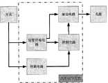
一种通过按键执行亮度调节的装置,包括短暂供电电路、控制电路、检测电路以及驱动电路,其特征在于:A device for performing brightness adjustment through buttons, including a short-term power supply circuit, a control circuit, a detection circuit, and a drive circuit, characterized in that:
短暂供电电路,包括电解电容,与控制电路和驱动电路连接,在断电状态下能够为控制电路和驱动电路短暂供电,在一段时间内维持控制电路里易失性存储单元中的数据;The short-term power supply circuit, including electrolytic capacitors, is connected to the control circuit and the drive circuit, and can supply power to the control circuit and the drive circuit for a short time in a power-off state, and maintain the data in the volatile storage unit in the control circuit for a period of time;
控制电路,所述控制电路的输入端连接检测电路,输出端连接驱动电路,接收来自检测电路的取样信号,处理后向驱动电路输出控制信号,控制电路中固化有控制程序,控制程序调节光源亮度的流程如下:A control circuit, the input end of the control circuit is connected to the detection circuit, the output end is connected to the driving circuit, receives the sampling signal from the detection circuit, and outputs the control signal to the driving circuit after processing, and a control program is solidified in the control circuit, and the control program adjusts the brightness of the light source The process is as follows:
A.控制电路控制驱动电路驱动光源亮度由暗到明逐渐变化,当到达亮度的最大值后,再由明到暗逐渐变化;A. The control circuit controls the driving circuit to drive the brightness of the light source to gradually change from dark to bright, and then gradually change from bright to dark after reaching the maximum brightness;
B.判断控制电路是否接收到由检测电路检测到的低电平输入,若是,执行步骤C;若否,则控制电路继续控制驱动电路驱动光源亮度由暗到明或者由明到暗逐渐变化;B. Determine whether the control circuit has received the low-level input detected by the detection circuit, if so, perform step C; if not, the control circuit continues to control the drive circuit to drive the brightness of the light source to gradually change from dark to bright or from bright to dark;
C.在检测到低电平输入的同时,短暂供电电路继续给控制电路供电,控制电路将与当前光源亮度相对应的亮度状态信息保存在易失性存储单元中;判断控制电路是否接收到由检测电路检测到的高电平输入,若是则继续判断在易失性存储单元中是否保存有亮度状态信息,若没有保存亮度状态信息,则控制电路继续控制驱动电路驱动光源亮度由暗到明或者由明到暗逐渐变化,并返回步骤B,若保存有亮度状态信息,则执行步骤D;若控制电路没有接收到由检测电路检测到的高电平输入,则执行步骤F;C. While detecting the low-level input, the short-term power supply circuit continues to supply power to the control circuit, and the control circuit stores the brightness state information corresponding to the current light source brightness in the volatile storage unit; judge whether the control circuit receives If the high-level input detected by the detection circuit continues to judge whether there is brightness state information stored in the volatile memory unit, if the brightness state information is not saved, the control circuit continues to control the drive circuit to drive the brightness of the light source from dark to bright or Gradually change from bright to dark, and return to step B, if the brightness state information is saved, then execute step D; if the control circuit does not receive the high level input detected by the detection circuit, then execute step F;
D.控制电路控制驱动电路驱动光源按照所保存的亮度状态信息对应的亮度工作;判断控制电路是否接收到由检测电路检测到的低电平输入,如果没有低电平输入,则继续控制驱动电路驱动光源按照所保存的亮度状态信息对应的亮度工作;若有低电平输入,则控制电路清除保存在易失性存储单元中的亮度状态信息,执行步骤E;D. The control circuit controls the drive circuit to drive the light source to work according to the brightness corresponding to the stored brightness state information; judge whether the control circuit receives a low-level input detected by the detection circuit, and if there is no low-level input, continue to control the drive circuit Drive the light source to work according to the brightness corresponding to the saved brightness state information; if there is a low-level input, the control circuit clears the brightness state information stored in the volatile memory unit, and executes step E;
E.判断控制电路是否接收到由检测电路检测到的高电平输入,如果没有高电平输入,则执行步骤F;如果有高电平输入,则返回执行步骤A;E. Judging whether the control circuit has received the high-level input detected by the detection circuit, if there is no high-level input, then perform step F; if there is a high-level input, then return to perform step A;
F.执行等待循环程序,结束;F. Execute the waiting loop program and end;
检测电路,用于获取开关的导通、断开信号并将获取的信号转换为高低电平发送给控制电路,其中,检测电路检测到的高电平输入是由用户对开关进行闭合操作引发的,检测电路检测到的低电平输入是由用户对开关进行断开操作所引发的;The detection circuit is used to obtain the switch on and off signals and convert the obtained signals into high and low levels to send to the control circuit, wherein the high level input detected by the detection circuit is caused by the user closing the switch , the low-level input detected by the detection circuit is caused by the user turning off the switch;
驱动电路,用于根据控制电路的控制信号来调节光源的亮度,并且与短暂供电电路连接,在开关断开后,光源在短暂时间内不会熄灭;The driving circuit is used to adjust the brightness of the light source according to the control signal of the control circuit, and is connected to the short-term power supply circuit. After the switch is turned off, the light source will not go out within a short time;
本发明有益的技术效果在于:The beneficial technical effects of the present invention are:
1)只需通过一个电源开关的通断转换就可方便地实现光源亮度的调节,不仅省去了专门外接的调光开关和其他辅助装置,而且在安装使用时无需对原有的电器布线进行改造,极大地方便了用户,也大大地降低了成本;1) The brightness of the light source can be adjusted conveniently only through the on-off conversion of a power switch. Transformation greatly facilitates users and greatly reduces costs;
2)通过电容的放电来维持控制电路内程序的运行,使其对掉电过程做出响应,实现工作模式的转换,与采用带有非易失性存储功能的单片机来保持掉电情况下保存信息的方法相比极大的降低了成本;此外,在开关断开后,短暂供电电路还能够继续为驱动电路提供电能,使得在开关断开后,光源不至于熄灭,在开关动作的时间内维持原有的亮度,保证了光源为我们提供电能的连续性,使得调光更加方便;2) Maintain the operation of the program in the control circuit through the discharge of the capacitor, make it respond to the power-off process, realize the conversion of the working mode, and use a single-chip microcomputer with a non-volatile storage function to keep the power-off situation Compared with the method of information, the cost is greatly reduced; in addition, after the switch is turned off, the short-term power supply circuit can continue to provide power for the drive circuit, so that after the switch is turned off, the light source will not go out, and within the time of the switch action Maintain the original brightness, ensure the continuity of power provided by the light source, and make dimming more convenient;
3)本调节装置主要利用预设的控制程序,通过监控用户的每一次操作电源开关的动作来实现对本调光节能灯调光功能的控制与执行,只需要一次选择,既可以选择所需要的亮度,无需频繁的切换开关,使得控制更加方便,而且可以随意的控制光源的亮度,相比现有的技术更加先进。3) This adjustment device mainly uses the preset control program to realize the control and execution of the dimming function of the dimming energy-saving lamp by monitoring each action of the user's operation of the power switch. Only one selection is required, and the required one can be selected. Brightness, no need to switch switches frequently, making the control more convenient, and the brightness of the light source can be controlled at will, which is more advanced than the existing technology.
附图说明Description of drawings
图1为该亮度调节装置的结构示意图;Fig. 1 is the structural representation of this brightness adjusting device;
图2为该亮度调节装置的控制流程图;Fig. 2 is the control flowchart of this brightness adjusting device;
图3为该亮度调节装置的短暂供电电路的电路图;Fig. 3 is a circuit diagram of the transient power supply circuit of the brightness adjustment device;
图4为该亮度调节装置的检测电路的电路图。FIG. 4 is a circuit diagram of a detection circuit of the brightness adjustment device.
具体实施方式Detailed ways
下面结合附图对本发明的实施方式做进一步的说明。Embodiments of the present invention will be further described below in conjunction with the accompanying drawings.
如图2所示,本实施例提供一种通过按键执行亮度调节的方法,该方法基于通过控制电路向驱动电路发送控制光源亮度的信号来控制光源的亮度,具体该方法包括:As shown in FIG. 2, this embodiment provides a method for performing brightness adjustment through buttons. The method controls the brightness of the light source based on sending a signal to control the brightness of the light source through the control circuit to the drive circuit. Specifically, the method includes:
A.首先,控制电路控制驱动电路驱动光源亮度由暗到明逐渐变化,当到达亮度的最大值后,再由明到暗逐渐变化。具体为:在控制电路中固化一程序,该程序对应驱动光源按照先由暗逐渐到亮,然后再由亮逐渐变到暗的状态工作的控制信号,在首次打开控制驱动电路通断的开关,使得控制器开始工作,驱动电路导通,控制电路控制光源驱动电路驱动光源按照由暗逐渐到亮,然后再由亮逐渐变到暗的状态工作,在开关断开之前,所述光源依然按照上述的秩序循环往复变化,直到开关断开时,停止变化。所述控制信号为PWM控制信号。A. First, the control circuit controls the driving circuit to drive the brightness of the light source to gradually change from dark to bright, and then gradually change from bright to dark after reaching the maximum brightness. Specifically: solidify a program in the control circuit, the program corresponds to the control signal that drives the light source from dark to bright first, and then gradually changes from bright to dark, and turns on the switch that controls the on-off of the drive circuit for the first time. Make the controller start to work, the driving circuit is turned on, the control circuit controls the light source driving circuit to drive the light source to work in a state of gradually changing from dark to bright, and then gradually changing from bright to dark. Before the switch is turned off, the light source still operates according to the above The order changes repeatedly until the switch is turned off and stops changing. The control signal is a PWM control signal.
B.判断控制电路是否接收到由检测电路检测到的低电平输入,若是,执行步骤C;若否,则控制电路继续控制驱动电路驱动光源亮度由暗到明或者由明到暗逐渐变化;B. Determine whether the control circuit has received the low-level input detected by the detection circuit, if so, perform step C; if not, the control circuit continues to control the drive circuit to drive the brightness of the light source to gradually change from dark to bright or from bright to dark;
C.在检测到低电平输入的同时,短暂供电电路继续给控制电路供电,控制电路将与当前光源亮度相对应的亮度状态信息保存在易失性存储单元中;判断控制电路是否接收到由检测电路检测到的高电平输入,若是则继续判断在易失性存储单元中是否保存有亮度状态信息,若没有保存亮度状态信息,则控制电路继续控制驱动电路驱动光源亮度由暗到明或者由明到暗逐渐变化,并返回步骤B,若保存有亮度状态信息,则执行步骤D;若控制电路没有接收到由检测电路检测到的高电平输入,则执行步骤F;C. While detecting the low-level input, the short-term power supply circuit continues to supply power to the control circuit, and the control circuit stores the brightness state information corresponding to the current light source brightness in the volatile storage unit; judge whether the control circuit receives If the high-level input detected by the detection circuit continues to judge whether there is brightness state information stored in the volatile memory unit, if the brightness state information is not saved, the control circuit continues to control the drive circuit to drive the brightness of the light source from dark to bright or Gradually change from bright to dark, and return to step B, if the brightness state information is saved, then execute step D; if the control circuit does not receive the high level input detected by the detection circuit, then execute step F;
D.控制电路控制驱动电路驱动光源按照所保存的亮度状态信息对应的亮度工作;判断控制电路是否接收到由检测电路检测到的低电平输入,如果没有低电平输入,则继续控制驱动电路驱动光源按照所保存的亮度状态信息对应的亮度工作;若有低电平输入,则控制电路清除保存在易失性存储单元中的亮度状态信息,执行步骤E;D. The control circuit controls the drive circuit to drive the light source to work according to the brightness corresponding to the stored brightness state information; judge whether the control circuit receives a low-level input detected by the detection circuit, and if there is no low-level input, continue to control the drive circuit Drive the light source to work according to the brightness corresponding to the saved brightness state information; if there is a low-level input, the control circuit clears the brightness state information stored in the volatile memory unit, and executes step E;
E.判断控制电路是否接收到由检测电路检测到的高电平输入,如果没有高电平输入,则执行步骤F;如果有高电平输入,则返回执行步骤A;E. Judging whether the control circuit has received the high-level input detected by the detection circuit, if there is no high-level input, then perform step F; if there is a high-level input, then return to perform step A;
F.执行等待循环程序,结束;F. Execute the waiting loop program and end;
具体为:当在光源工作在A步骤所述的状态时,断开开关,则驱动电路和控制电路失去了由开关提供的供电,但是短暂供电电路继续为控制电路提供电能,继续驱动控制电路工作,控制电路通过检测电路检测到的开关电路的电压信号获取开关的通断信号,当控制电路获知开关断开后,控制电路获取开关电路从导通到断开运行的时间,并根据该时间从固化程序中找出开关断开瞬间的光源亮度状态信息,并将该亮度状态信息存储在控制电路的易失性存储单元中。短暂供电电路能够提供给控制电路电量的时间依据短暂供电电路的储能元件的放电时间来决定,该储能元件可为电感、电容或电池。Specifically: when the light source is working in the state described in step A, the switch is turned off, the drive circuit and the control circuit lose the power supply provided by the switch, but the short-term power supply circuit continues to provide power for the control circuit, and continues to drive the control circuit to work , the control circuit obtains the on-off signal of the switch through the voltage signal of the switch circuit detected by the detection circuit. In the curing program, find out the brightness state information of the light source at the moment when the switch is turned off, and store the brightness state information in the volatile storage unit of the control circuit. The time during which the short-term power supply circuit can provide power to the control circuit is determined by the discharge time of the energy storage element of the short-term power supply circuit, and the energy storage element can be an inductor, a capacitor or a battery.
当控制电路将亮度状态信息存储起来后,就等待着开关的再次闭合,如果在短暂供电电路电量耗完后闭合,则存储的亮度状态信息消失,那么将返回步骤A,控制电路控制驱动电路驱动光源按照步骤A所述的状态变化。如果存储的亮度状态信息不存在了,这表明在短暂供电电路电量耗尽前没有开关闭合,则控制电路继续控制驱动电路驱动光源亮度由暗到明或者由明到暗逐渐变化;若控制电路没有接收到由检测电路检测到的高电平输入,则等待短暂供电电路电量耗尽,结束控制流程;如果在短暂供电电路电量耗尽前闭合,则存储的亮度状态信息依然存在,则控制电路控制驱动电路驱动光源按照所保存的亮度状态信息对应的亮度工作。After the control circuit stores the brightness state information, it waits for the switch to be closed again. If it is closed after the short-term power supply circuit is exhausted, the stored brightness state information disappears, then it will return to step A, and the control circuit controls the drive circuit to drive The light source changes state as described in step A. If the stored brightness state information does not exist, it indicates that the switch is not closed before the short-term power supply circuit is exhausted, and the control circuit continues to control the driving circuit to drive the light source brightness to gradually change from dark to bright or from bright to dark; if the control circuit does not After receiving the high-level input detected by the detection circuit, wait for the short-term power supply circuit to be exhausted, and end the control process; if it is closed before the short-term power supply circuit is exhausted, the stored brightness status information still exists, and the control circuit controls The driving circuit drives the light source to work according to the brightness corresponding to the stored brightness state information.
接下来,判断控制电路是否接收到由检测电路检测到的低电平输入,如果没有低电平输入,则继续控制驱动电路驱动光源按照所保存的亮度状态信息对应的亮度工作;若有低电平输入,则控制电路清除保存在易失性存储单元中的亮度状态信息,判断控制电路是否接收到由检测电路检测到的高电平输入,如果没有低电平输入,则等待短暂供电电路电量耗尽,结束控制流程;如果有低电平输入,则返回执行步骤A;Next, judge whether the control circuit has received the low-level input detected by the detection circuit, if there is no low-level input, continue to control the driving circuit to drive the light source to work according to the brightness corresponding to the stored brightness state information; if there is a low-level input level input, the control circuit clears the brightness state information stored in the volatile memory unit, and judges whether the control circuit receives a high level input detected by the detection circuit, and if there is no low level input, waits for the short-term power supply circuit power Exhausted, end the control process; if there is a low level input, return to step A;
如此设计的优势在于,如果人们在选择亮度时错过了最佳亮度,还可以将开关关掉并且迅速打开,重新选择,无需等待,提高了调光的方便性。The advantage of such a design is that if people miss the optimal brightness when selecting the brightness, they can also turn off the switch and turn it on quickly, and re-select without waiting, which improves the convenience of dimming.
需要说明的是:在开关断开后,驱动电路断开,停止给光源供电,因为每次调光都需要将开关断开,使得光源都停止供电,如果光源没有其他供电电路对其进行供电,则会使光源熄灭,如果每次在调光的时候都必须使光源熄灭,则会给工作和生活带来不便,而且经常随着开关次数的增多,光源的使用寿命势必会大大降低,所以需要设计储能元件在开关断开后对光源进行短暂供电。如图1所示,装置中包括短暂供电电路,包括电解电容,与控制电路和驱动电路连接,在断电状态下能够为控制电路和驱动电路短暂供电,在一段时间内维持控制电路里易失性存储单元中的数据;在开关闭合后,又重新对短暂供电电路进行充电,较优的储能元件为电容或者电感。由于设计了短暂供电电路对光源进行继续供电,使得光源即使在断开开关的瞬间,也继续保持同样的亮度,即光源的电流和电压值保持不变,所以在光源处于明暗渐次变化状态且在驱动电路断开瞬间,控制电路能够获取驱动电路断开时驱动电路输出端的电流或/和电压值,所述的电流或/和电压值即对应驱动电路断开时的光源的亮度状态,将该电流或/和电压值暂时存储起来,即相当于存储了驱动电路断开时的光源亮度状态信息。It should be noted that after the switch is turned off, the drive circuit is disconnected and the power supply to the light source is stopped, because the switch needs to be turned off every time the light is adjusted, so that the light source stops supplying power. If the light source has no other power supply circuit to supply power to it, If the light source must be turned off every time the light is adjusted, it will bring inconvenience to work and life, and often with the increase of the number of switches, the service life of the light source will be greatly reduced, so it is necessary to The energy storage element is designed to supply power to the light source briefly after the switch is turned off. As shown in Figure 1, the device includes a short-term power supply circuit, including an electrolytic capacitor, which is connected to the control circuit and the drive circuit, and can supply power to the control circuit and the drive circuit for a short period of time in a power-off state, maintaining the volatile state of the control circuit for a period of time. The data in the permanent storage unit; after the switch is closed, the short-term power supply circuit is charged again, and the better energy storage element is a capacitor or an inductor. Since the short-term power supply circuit is designed to continue to supply power to the light source, the light source will continue to maintain the same brightness even when the switch is turned off, that is, the current and voltage values of the light source remain unchanged, so when the light source is in a state of gradual change in brightness and darkness. The moment the drive circuit is disconnected, the control circuit can acquire the current or/and voltage value at the output end of the drive circuit when the drive circuit is disconnected, the current or/and voltage value corresponds to the brightness state of the light source when the drive circuit is disconnected, and the Temporarily storing the current or/and voltage value is equivalent to storing the brightness state information of the light source when the driving circuit is disconnected.
短暂供电电路的电路结构如图3所示,包括100欧电阻R3,220K欧的电阻R4,0.47uF的电解电容C4,图3中示出了各个元件的连接关系。短暂供电电路的供电时间依据具体情况有不同的设计,范围大概在2至10秒左右。The circuit structure of the short-term power supply circuit is shown in Figure 3, including a 100-ohm resistor R3, a 220K-ohm resistor R4, and a 0.47uF electrolytic capacitor C4. Figure 3 shows the connection relationship of each component. The power supply time of the short-term power supply circuit has different designs depending on the specific situation, and the range is about 2 to 10 seconds.
如图1所示,装置中还包括了检测电路,检测电路的电路结构如图4所示,检测电路由电容C1、C2,二极管D以及电阻R1、R2组成,其中,C1和C2的一端接地,C2的另一端与二极管D的正极连接,C1的另一端与二极管D的负极之间连接有电阻R1,C1的两端并联有电阻R2,电容C1与电阻R1的公共连接端与控制电路连接,电容C2与二极管D正极的连接端与开关连接。As shown in Figure 1, the device also includes a detection circuit, the circuit structure of the detection circuit is shown in Figure 4, the detection circuit is composed of capacitors C1, C2, diode D and resistors R1, R2, wherein one end of C1 and C2 is grounded , the other end of C2 is connected to the anode of diode D, the resistor R1 is connected between the other end of C1 and the cathode of diode D, the two ends of C1 are connected in parallel with resistor R2, the common connection end of capacitor C1 and resistor R1 is connected to the control circuit , the connection end of the capacitor C2 and the anode of the diode D is connected to the switch.
驱动电路,用于根据控制电路的控制信号来调节光源的亮度,并且与短暂供电电路连接,在开关断开后,光源在短暂时间内不会熄灭。The driving circuit is used to adjust the brightness of the light source according to the control signal of the control circuit, and is connected to the short-term power supply circuit. After the switch is turned off, the light source will not be extinguished within a short time.
本发明的保护范围并不限于上述的实施例,显然,本领域的技术人员可以对本发明进行各种改动和变形而不脱离本发明的范围和精神。倘若这些改动和变形属于本发明权利要求及其等同技术的范围内,则本发明的意图也包含这些改动和变形在内。The scope of protection of the present invention is not limited to the above-mentioned embodiments. Obviously, those skilled in the art can make various changes and modifications to the present invention without departing from the scope and spirit of the present invention. If these changes and modifications fall within the scope of the claims of the present invention and their equivalent technologies, the intent of the present invention is also to include these changes and modifications.
Claims (2)
Translated fromChinesePriority Applications (1)
| Application Number | Priority Date | Filing Date | Title |
|---|---|---|---|
| CN2011103075400ACN102438361B (en) | 2011-10-11 | 2011-10-11 | Device capable of executing brightness regulation through press key |
Applications Claiming Priority (1)
| Application Number | Priority Date | Filing Date | Title |
|---|---|---|---|
| CN2011103075400ACN102438361B (en) | 2011-10-11 | 2011-10-11 | Device capable of executing brightness regulation through press key |
Publications (2)
| Publication Number | Publication Date |
|---|---|
| CN102438361A CN102438361A (en) | 2012-05-02 |
| CN102438361Btrue CN102438361B (en) | 2013-12-04 |
Family
ID=45986167
Family Applications (1)
| Application Number | Title | Priority Date | Filing Date |
|---|---|---|---|
| CN2011103075400AExpired - Fee RelatedCN102438361B (en) | 2011-10-11 | 2011-10-11 | Device capable of executing brightness regulation through press key |
Country Status (1)
| Country | Link |
|---|---|
| CN (1) | CN102438361B (en) |
Families Citing this family (3)
| Publication number | Priority date | Publication date | Assignee | Title |
|---|---|---|---|---|
| CN105392239B (en)* | 2015-12-23 | 2018-01-02 | 冷俊 | L ED lamp with adjustable brightness |
| CN106304479A (en)* | 2016-08-19 | 2017-01-04 | 唐晓云 | A kind of intelligent lighting switching LED color lamp of microcomputerized control |
| CN109041345B (en)* | 2018-08-17 | 2024-03-05 | 赛尔富电子有限公司 | Method capable of manually setting dimming range of lamp and lamp system |
Citations (3)
| Publication number | Priority date | Publication date | Assignee | Title |
|---|---|---|---|---|
| CN1874631A (en)* | 2005-05-31 | 2006-12-06 | 台达电子工业股份有限公司 | Light source system and control method thereof |
| JP2009021535A (en)* | 2007-07-11 | 2009-01-29 | Ind Technol Res Inst | Light source device and its driving device |
| CN201860492U (en)* | 2010-11-10 | 2011-06-08 | 武汉理工大学 | Light modulating device for LED illumination lamp |
- 2011
- 2011-10-11CNCN2011103075400Apatent/CN102438361B/ennot_activeExpired - Fee Related
Patent Citations (3)
| Publication number | Priority date | Publication date | Assignee | Title |
|---|---|---|---|---|
| CN1874631A (en)* | 2005-05-31 | 2006-12-06 | 台达电子工业股份有限公司 | Light source system and control method thereof |
| JP2009021535A (en)* | 2007-07-11 | 2009-01-29 | Ind Technol Res Inst | Light source device and its driving device |
| CN201860492U (en)* | 2010-11-10 | 2011-06-08 | 武汉理工大学 | Light modulating device for LED illumination lamp |
Also Published As
| Publication number | Publication date |
|---|---|
| CN102438361A (en) | 2012-05-02 |
Similar Documents
| Publication | Publication Date | Title |
|---|---|---|
| CN101742771B (en) | Portable type lamp, light dimming circuit and light dimming method | |
| CN103229597B (en) | A dimming driving method, device and dimming lamp | |
| US9119245B1 (en) | LED driving system for switched dimming control and dimming method using the same | |
| CN101309545B (en) | Light modulating energy-saving lamp suitable for one-touch control | |
| CN104349524B (en) | Mains switch event detection for LED assemblies | |
| JP2006332045A (en) | Staged dimming ballast for fluorescent lamp | |
| KR20080080956A (en) | Stepless dimming fluorescent lamps and ballasts of these fluorescent lamps | |
| CN105392239B (en) | L ED lamp with adjustable brightness | |
| CN1925714B (en) | Multi-stage dimming control device and dimming control method for gas discharge lamp | |
| CN102098854B (en) | Dimming driving method | |
| JP5834235B2 (en) | Solid-state light source lighting device and lighting apparatus and lighting system using the same | |
| CN202014402U (en) | Light-emitting diode light adjusting device, lamp and light adjusting system | |
| WO2015161379A1 (en) | Dimmable led light | |
| CN102438361B (en) | Device capable of executing brightness regulation through press key | |
| CN101882881B (en) | Method and device for reducing capacitance value usage | |
| CN108601161A (en) | A kind of sectional power supply formula Multi-way touch Bluetooth control list firewire switching circuit | |
| WO2018121707A1 (en) | Device for controlling brightness of mobile phone screen | |
| CN102438362B (en) | One key type brightness adjusting device | |
| CN102438363B (en) | Light source brightness adjusting device | |
| CN101640967B (en) | Fluorescent lamp driving circuit, fluorescent lamp dimming circuit and method | |
| CN102869156A (en) | Method for setting brightness of LED lamp by using on-off coding of power switch | |
| CN202551430U (en) | Dimming lamp | |
| US11019698B2 (en) | Retrofit light emitting diode, LED, lighting device with reduced power consumption in standby mode | |
| TWI555438B (en) | Adaptive current regulation for solid state lighting | |
| JPH11283756A (en) | Lighting equipment |
Legal Events
| Date | Code | Title | Description |
|---|---|---|---|
| DD01 | Delivery of document by public notice | Addressee:Ningbo Ruitong New Material Technology Co., Ltd. Document name:Notification of Passing Preliminary Examination of the Application for Invention | |
| C06 | Publication | ||
| PB01 | Publication | ||
| C10 | Entry into substantive examination | ||
| SE01 | Entry into force of request for substantive examination | ||
| DD01 | Delivery of document by public notice | Addressee:Ningbo Ruitong New Material Technology Co., Ltd. Xu Bo Document name:Notification of Patent Invention Entering into Substantive Examination Stage | |
| DD01 | Delivery of document by public notice | Addressee:Ningbo Ruitong New Material Technology Co., Ltd. Document name:Notification of Publication of the Application for Invention | |
| DD01 | Delivery of document by public notice | Addressee:Ningbo Ruitong New Material Technology Co., Ltd. Document name:the First Notification of an Office Action | |
| DD01 | Delivery of document by public notice | Addressee:Ningbo Ruitong New Material Technology Co., Ltd. Document name:Notification to Go Through Formalities of Registration | |
| C14 | Grant of patent or utility model | ||
| GR01 | Patent grant | ||
| ASS | Succession or assignment of patent right | Owner name:ANYANG POWER SUPPLY COMPANY, STATE GRID HENAN ELEC Effective date:20140429 Owner name:STATE GRID CORPORATION OF CHINA Free format text:FORMER OWNER: NINGBO RUITONG NEW MATERIAL TECHNOLOGY CO., LTD. Effective date:20140429 | |
| C41 | Transfer of patent application or patent right or utility model | ||
| COR | Change of bibliographic data | Free format text:CORRECT: ADDRESS; FROM: 315177 NINGBO, ZHEJIANG PROVINCE TO: 100031 XICHENG, BEIJING | |
| TR01 | Transfer of patent right | Effective date of registration:20140429 Address after:100031 Xicheng District West Chang'an Avenue, No. 86, Beijing Patentee after:State Grid Corporation of China Patentee after:ANYANG POWER SUPPLY COMPANY, STATE GRID HENAN ELECTRIC POWER CO., LTD. Address before:315177 Zhejiang province Ningbo city Yinzhou District town water village turnip Patentee before:Ningbo Ruitong New Material Technology Co., Ltd. | |
| CF01 | Termination of patent right due to non-payment of annual fee | Granted publication date:20131204 Termination date:20161011 | |
| CF01 | Termination of patent right due to non-payment of annual fee |