CN102436897A - Flexible Rogowski coil used for detecting direct-current system short-circuit current and method for designing same - Google Patents
Flexible Rogowski coil used for detecting direct-current system short-circuit current and method for designing sameDownload PDFInfo
- Publication number
- CN102436897A CN102436897ACN2011102731440ACN201110273144ACN102436897ACN 102436897 ACN102436897 ACN 102436897ACN 2011102731440 ACN2011102731440 ACN 2011102731440ACN 201110273144 ACN201110273144 ACN 201110273144ACN 102436897 ACN102436897 ACN 102436897A
- Authority
- CN
- China
- Prior art keywords
- coil
- flexible
- luo
- plug
- rogowski coil
- Prior art date
- Legal status (The legal status is an assumption and is not a legal conclusion. Google has not performed a legal analysis and makes no representation as to the accuracy of the status listed.)
- Granted
Links
- 238000000034methodMethods0.000titleclaimsabstractdescription22
- 238000001514detection methodMethods0.000claimsabstractdescription10
- 230000010354integrationEffects0.000claimsabstractdescription7
- 238000005259measurementMethods0.000claimsdescription13
- 239000002356single layerSubstances0.000claimsdescription9
- 239000010410layerSubstances0.000claimsdescription6
- 239000011810insulating materialSubstances0.000claimsdescription5
- 238000009413insulationMethods0.000claimsdescription5
- 230000001681protective effectEffects0.000claimsdescription3
- 238000010183spectrum analysisMethods0.000claimsdescription3
- 210000000988bone and boneAnatomy0.000claims10
- 239000012774insulation materialSubstances0.000claims1
- 239000011159matrix materialSubstances0.000claims1
- 238000004804windingMethods0.000abstractdescription15
- 238000005070samplingMethods0.000abstractdescription14
- 239000000463materialSubstances0.000description6
- -1polytetrafluoroethylenePolymers0.000description4
- 229920001343polytetrafluoroethylenePolymers0.000description4
- 239000004810polytetrafluoroethyleneSubstances0.000description4
- 229920002379silicone rubberPolymers0.000description4
- 238000010586diagramMethods0.000description3
- 239000004945silicone rubberSubstances0.000description3
- 230000001052transient effectEffects0.000description3
- 230000008878couplingEffects0.000description2
- 238000010168coupling processMethods0.000description2
- 238000005859coupling reactionMethods0.000description2
- 238000009776industrial productionMethods0.000description2
- 230000005291magnetic effectEffects0.000description2
- XEEYBQQBJWHFJM-UHFFFAOYSA-NIronChemical group[Fe]XEEYBQQBJWHFJM-UHFFFAOYSA-N0.000description1
- 239000004809TeflonSubstances0.000description1
- 229920006362Teflon®Polymers0.000description1
- 238000005260corrosionMethods0.000description1
- 238000012938design processMethods0.000description1
- 238000009826distributionMethods0.000description1
- 230000000694effectsEffects0.000description1
- 230000005674electromagnetic inductionEffects0.000description1
- 230000005294ferromagnetic effectEffects0.000description1
- 230000006698inductionEffects0.000description1
- 230000001939inductive effectEffects0.000description1
- 238000009434installationMethods0.000description1
- WABPQHHGFIMREM-UHFFFAOYSA-Nlead(0)Chemical compound[Pb]WABPQHHGFIMREM-UHFFFAOYSA-N0.000description1
- 230000035699permeabilityEffects0.000description1
- 238000001228spectrumMethods0.000description1
- 230000003313weakening effectEffects0.000description1
Images


Landscapes
- Measuring Instrument Details And Bridges, And Automatic Balancing Devices (AREA)
Abstract
Translated fromChinese
Description
Translated fromChinese技术领域technical field
本发明属于电子式电流互感器,具体涉及一种用于直流系统短路电流测量的罗氏线圈及其设计方法,。The invention belongs to electronic current transformers, and in particular relates to a Rogowski coil for short-circuit current measurement in a DC system and a design method thereof.
背景技术Background technique
为了在直流电力系统发生短路故障时能够快速的检测到故障,同时为了更方便的与数字式智能单元相连接以实现数字化测量与保护,基于电磁感应原理的罗氏线圈被广泛应用。In order to quickly detect the fault when a short-circuit fault occurs in the DC power system, and to connect with the digital intelligent unit more conveniently to realize digital measurement and protection, Rogowski coils based on the principle of electromagnetic induction are widely used.
与其他的暂态电流检测方法相比较,空心式罗氏线圈所采用的骨架为非铁磁性绝缘材料,由于其不含铁心,理论上不存在磁饱和问题,几乎不受被测电流大小的限制,非常适合于对大电流的测量。Compared with other transient current detection methods, the skeleton of the air-core Rogowski coil is a non-ferromagnetic insulating material. Since it does not contain an iron core, there is no magnetic saturation problem in theory, and it is almost not limited by the magnitude of the measured current. Very suitable for the measurement of large currents.
在针对暂态大电流的测量中,以往的基于罗氏线圈的测量,一方面工艺上的性能仍有待改进,以往的空心式罗氏线圈,由于绕线所采用漆包线较细,当罗氏线圈受到外力作用时,漆包线容易被拉断,造成罗氏线圈产品的故障;另一方面,缺少一种流程化的设计方法做为指导,以更好的与数字化智能单元相连接以实现数字化测量与保护。In the measurement of transient large currents, the previous measurement based on Rogowski coils, on the one hand, still needs to be improved in terms of technological performance. The previous hollow Rogowski coils, because the enameled wire used for winding is relatively thin, when the Rogowski coils are subjected to external forces At the same time, the enameled wire is easily broken, causing the failure of Rogowski coil products; on the other hand, there is a lack of a process design method as a guide to better connect with the digital intelligent unit to achieve digital measurement and protection.
发明内容Contents of the invention
本发明的目的在于提供一种能够将高幅值暂态电流信号转换成可与后级数字化智能单元相连接的高精度的用于直流系统短路电流检测的柔性罗氏线圈及其设计方法。The purpose of the present invention is to provide a high-precision flexible Rogowski coil for DC system short-circuit current detection and its design method, which can convert high-amplitude transient current signals into a high-precision digital intelligent unit that can be connected to the subsequent stage.
为达到上述目的,本发明的柔性罗氏线圈包括均匀绕制在带有开口的圆环形柔性骨架上的线圈及回线,在线圈及回线外套装有外层绝缘套管,圆环形柔性骨架的开口上安装有与线圈及回线相连接的插入式接口,线圈出线经插入式接口的孔引出后与取样电阻模块相连,取样电阻模块引出信号与后级积分电路相连接。In order to achieve the above object, the flexible Rogowski coil of the present invention includes a coil and a loop uniformly wound on a circular flexible skeleton with an opening, and an outer insulating sleeve is placed on the coil and the loop, and the circular flexible The opening of the frame is equipped with a plug-in interface connected to the coil and the return line. The coil outlet is connected to the sampling resistor module after being drawn out through the hole of the plug-in interface, and the signal drawn from the sampling resistor module is connected to the subsequent integration circuit.
所述的取样电阻模块包括经插入式接口与线圈出线相连接的取样电阻,所述取样电阻的两端同时与保护外壳上的BNC插座相连接。The sampling resistance module includes a sampling resistance connected to the coil outlet through a plug-in interface, and both ends of the sampling resistance are connected to the BNC socket on the protective shell at the same time.
所述的柔性骨架由柔性绝缘材料构成,且该柔性骨架的几何中间部分开设有使回线通过的通孔。The flexible frame is made of flexible insulating material, and a through hole is opened in the geometrically middle part of the flexible frame for the return wire to pass through.
所述的线圈及回线自柔性骨架的一端穿入柔性骨架的通孔,由另一端引出后以单层方式均匀的绕制在柔性骨架上,且在穿过柔性骨架通孔的回线上套装有起紧固和保护作用的聚四氟乙烯绝缘材料。The coils and loops are inserted into the through hole of the flexible frame from one end of the flexible frame, and are evenly wound on the flexible frame in a single layer after being led out from the other end, and on the loop passing through the through hole of the flexible frame The suit has Teflon insulation for fastening and protection.
所述的插入式接口的两端为凹型,插入式接口中间设有螺纹凹槽与取样电阻模块螺纹连接。Both ends of the plug-in interface are concave, and a threaded groove is provided in the middle of the plug-in interface to be threadedly connected to the sampling resistance module.
本发明的设计方法如下:Design method of the present invention is as follows:
1)先根据对直流系统呈指数变化的短路电流的频谱分析,确定罗氏线圈的频率下限,根据所得的频率下限确定外积分电路的时间常数;1) First, determine the lower limit of the frequency of the Rogowski coil according to the frequency spectrum analysis of the exponentially changing short-circuit current of the DC system, and determine the time constant of the outer integrating circuit according to the lower limit of the frequency obtained;
2)然后根据载流母线的尺寸,在保证绝缘条件满足的条件下确定罗氏线圈柔性骨架的尺寸并根据被测电流峰值和外积分电路的时间常数确定罗氏线圈的互感;2) Then, according to the size of the current-carrying busbar, the size of the flexible skeleton of the Rogowski coil is determined under the condition that the insulation condition is satisfied, and the mutual inductance of the Rogowski coil is determined according to the peak value of the measured current and the time constant of the external integration circuit;
3)首先判断单层线圈及回线是否满足罗氏线圈互感大小的要求,如果不能满足,则改变柔性骨架截面直径使单层线圈及回线满足互感大小的要求;3) First judge whether the single-layer coil and loop meet the requirements of the mutual inductance of the Rogowski coil, if not, change the cross-sectional diameter of the flexible skeleton so that the single-layer coil and loop meet the requirements of the mutual inductance;
4)如果满足罗氏线圈互感的要求则制作罗氏线圈并进行参数的测量,根据最佳匹配确定外接电阻的大小。4) If the requirements of the mutual inductance of the Rogowski coil are met, the Rogowski coil is made and the parameters are measured, and the size of the external resistance is determined according to the best match.
本发明所涉及的柔性空心式罗氏线圈,对罗氏线圈的结构工艺进行改进,在保证测量精度的前提下,提高了罗氏线圈的机械寿命。同时,提出了一种通用的设计方法,用于直流电力系统短路条件下电流的检测。The flexible hollow Rogowski coil involved in the present invention improves the structural process of the Rogowski coil, and improves the mechanical life of the Rogowski coil on the premise of ensuring measurement accuracy. At the same time, a general design method is proposed for current detection under short-circuit conditions in DC power systems.
本发明所提出的用于直流系统短路电流检测的柔性罗氏线圈,骨架材料应选取温度特性较好的材料,采用硅橡胶作为罗氏线圈的骨架材料。硅橡胶具有耐高温、耐高压、防水、防腐等性能,可以工作在-60℃~+180℃,具有良好的柔韧性,是柔性罗氏线圈骨架的理想材料。For the flexible Rogowski coil used in the detection of short-circuit current in the DC system proposed by the present invention, the skeleton material should be selected from materials with better temperature characteristics, and silicon rubber is used as the skeleton material of the Rogowski coil. Silicone rubber has the properties of high temperature resistance, high pressure resistance, waterproof, anti-corrosion, etc. It can work at -60°C ~ +180°C, has good flexibility, and is an ideal material for flexible Rogowski coil skeletons.
以往关于柔性罗氏线圈的回线,多是利用电缆本身芯线作为罗氏线圈回线,安装虽然简单,但是需要将芯线和漆包线进行焊接,这种工艺所带来的缺点就是将会增大线圈本身的自分布电容,降低线圈本身的频带宽度,影响测量精度。本发明所采用的罗氏线圈回线绕线工艺,回线和线圈绕线本身由一条线构成,具体是将硅橡胶电缆内芯抽掉,电缆内部套入聚四氟乙烯材料,作为漆包线的保护套管。所述的聚四氟乙烯绝缘材料套在漆包线的外层起紧固和防止断裂的保护作用,这种工艺制作的线圈结构紧凑,牢固性好,同时能保证很高的测量精度,适合工业生产使用。In the past, the return wire of the flexible Rogowski coil mostly used the core wire of the cable itself as the return wire of the Rogowski coil. Although the installation is simple, it needs to weld the core wire and the enameled wire. The disadvantage of this process is that it will increase the size of the coil. The self-distributed capacitance itself reduces the bandwidth of the coil itself and affects the measurement accuracy. In the Rogowski coil loop winding process adopted in the present invention, the loop wire and the coil winding itself are composed of a single wire, specifically, the inner core of the silicone rubber cable is removed, and polytetrafluoroethylene material is inserted inside the cable as a protection for the enameled wire. casing. The polytetrafluoroethylene insulating material is covered on the outer layer of the enameled wire to protect it from fastening and preventing breakage. The coil made by this process has a compact structure and good firmness, and at the same time can ensure high measurement accuracy, which is suitable for industrial production use.
所述的罗氏线圈绕线采用均匀密绕方式,这种绕线方式可以保证很好的抗干扰性能以及极大程度减小了绕线不均匀所带来的测量误差,同时密绕方式可以增大线圈的互感,提高了测量的信噪比。The Rogowski coil is wound in a uniform and dense manner, which can ensure good anti-interference performance and greatly reduce the measurement error caused by uneven winding. At the same time, the dense winding method can increase the The mutual inductance of the large coil improves the signal-to-noise ratio of the measurement.
附图说明Description of drawings
图1是罗氏线圈传感头的结构示意图;Fig. 1 is a structural schematic diagram of a Rogowski coil sensing head;
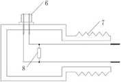
图2是罗氏线圈传感头取样电阻模块的结构示意图;Fig. 2 is a structural schematic diagram of a Rogowski coil sensing head sampling resistor module;
图3是罗氏线圈外积分电路的结构图;Fig. 3 is the structural diagram of the integrating circuit outside the Rogowski coil;
图4是外积分型罗氏线圈的设计流程图。Fig. 4 is the design flow chart of the outer integral Rogowski coil.
具体实施方式Detailed ways
下面结合附图做进一步详细说明。Further details will be described below in conjunction with the accompanying drawings.
参见图1,本发明包括柔性骨架2、线圈及回线1、外层绝缘套管3、取样电阻模块4及插入式接口5;所述线圈均匀绕制在柔性骨架2上,线圈回线埋置于柔性骨架2的几何中心,绕线两端通过插入式接口5经取样电阻模块4后引出;整个罗氏线圈构成一开口的圆环,首末端在使用时通过插入式接口5进行连接,罗氏线圈引出信号与后级积分电路相连接。本发明所采用的罗氏线圈回线绕线工艺,回线和线圈绕线本身由一条线构成,具体是将硅橡胶电缆内芯抽掉,电缆内部套入聚四氟乙烯材料,作为漆包线的保护套管。所述的聚四氟乙烯绝缘材料套在漆包线的外层起紧固和防止断裂的保护作用,这种工艺制作的线圈结构紧凑,牢固性好,同时能保证很高的测量精度,适合工业生产使用。Referring to Fig. 1, the present invention includes a
参见图2,线圈引出线经插入式接口5的孔引出后与取样电阻模块4中的取样电阻8焊接连接。取样电阻两端同时与保护外壳7上的BNC插座6焊接连接。BNC插座与屏蔽双绞线相连接,采用屏蔽层对削弱静电耦合和电磁耦合有很明显的作用,同时屏蔽层应保证良好接地。双绞线则通过减小来回线的感应面积来降低感应干扰。Referring to FIG. 2 , the lead wire of the coil is led out through the hole of the plug-in interface 5 and then welded to the
参见图3,外接积分电路采用有源积分,包括四个部分:即电压跟随电路、外积分电路、滤波电路、放大电路。Referring to Figure 3, the external integral circuit adopts active integral, which includes four parts: voltage follower circuit, external integral circuit, filter circuit, and amplifier circuit.
参见图4,本发明的外积分型的罗氏线圈的设计流程如下:Referring to Fig. 4, the design process of the Rogowski coil of the outer integral type of the present invention is as follows:
1)先根据对直流系统呈指数变化的短路电流的频谱分析,根据信号频谱特性中能量的分布特性确定罗氏线圈的频率下限,以保证能准确的反映原始信号的频率特性。由于外积分式罗氏线圈的频率下限决定于外积分电路的时间常数,即
2)然后根据载流母线的尺寸,在保证绝缘条件满足的条件下,即保证系统电压在设定距离下空气不被击穿,确定罗氏线圈柔性骨架的尺寸并根据被测电流峰值和外积分电路的时间常数确定罗氏线圈的互感,即根据公式
3)首先判断线圈及回线单层绕线方式是否满足罗氏线圈互感大小的要求,即判断假设在单层绕线且均匀密绕方式下是否能满足互感要求,这一点可以根据公式互感
4)如果满足罗氏线圈互感的要求则制作罗氏线圈并进行参数线圈自感Lc、线圈分布电容Cc及线圈内阻Rc的测量,根据最佳匹配,即
Claims (6)
Priority Applications (1)
| Application Number | Priority Date | Filing Date | Title |
|---|---|---|---|
| CN201110273144.0ACN102436897B (en) | 2011-09-15 | 2011-09-15 | A flexible Rogowski coil for DC system short-circuit current detection and its design method |
Applications Claiming Priority (1)
| Application Number | Priority Date | Filing Date | Title |
|---|---|---|---|
| CN201110273144.0ACN102436897B (en) | 2011-09-15 | 2011-09-15 | A flexible Rogowski coil for DC system short-circuit current detection and its design method |
Publications (2)
| Publication Number | Publication Date |
|---|---|
| CN102436897Atrue CN102436897A (en) | 2012-05-02 |
| CN102436897B CN102436897B (en) | 2014-01-29 |
Family
ID=45984906
Family Applications (1)
| Application Number | Title | Priority Date | Filing Date |
|---|---|---|---|
| CN201110273144.0AExpired - Fee RelatedCN102436897B (en) | 2011-09-15 | 2011-09-15 | A flexible Rogowski coil for DC system short-circuit current detection and its design method |
Country Status (1)
| Country | Link |
|---|---|
| CN (1) | CN102436897B (en) |
Cited By (17)
| Publication number | Priority date | Publication date | Assignee | Title |
|---|---|---|---|---|
| CN102751081A (en)* | 2012-07-03 | 2012-10-24 | 深圳市创银科技股份有限公司 | Flexible coil current transformer and production method thereof |
| CN103235169A (en)* | 2013-04-25 | 2013-08-07 | 国家电网公司 | Measuring device for pre-discharging current before insulation breakthrough at VFTO (very fast transient overvoltage) |
| CN103777055A (en)* | 2013-12-03 | 2014-05-07 | 国家电网公司 | Multiple Rogowski coil parallel-connected outer integration sensor |
| CN103852626A (en)* | 2012-11-30 | 2014-06-11 | 海洋王(东莞)照明科技有限公司 | Direct current circuit detection device |
| CN103852627A (en)* | 2012-11-30 | 2014-06-11 | 海洋王(东莞)照明科技有限公司 | An AC circuit current detection device |
| CN104076190A (en)* | 2013-03-29 | 2014-10-01 | 海洋王(东莞)照明科技有限公司 | Direct current detection circuit |
| CN104297558A (en)* | 2014-10-08 | 2015-01-21 | 中国科学院电工研究所 | Current measuring device |
| CN104345196A (en)* | 2014-10-30 | 2015-02-11 | 南京信息工程大学 | Active weak power frequency current induction coil |
| CN105448498A (en)* | 2015-12-07 | 2016-03-30 | 深圳供电局有限公司 | Traveling wave sensor and coil winding method of magnetic core of traveling wave sensor |
| CN106526302A (en)* | 2016-10-25 | 2017-03-22 | 华中科技大学 | A method for manufacturing high-performance turn-balanced air-core coils |
| CN106526279A (en)* | 2015-09-10 | 2017-03-22 | 赛米控电子股份有限公司 | Centering retaining device for Rogowski coil and method for arranging Rogowski coil |
| CN107768904A (en)* | 2017-10-26 | 2018-03-06 | 国网宁夏电力公司检修公司 | Plug-in Rogowski coil device |
| CN108594312A (en)* | 2018-07-30 | 2018-09-28 | 吉林省电力科学研究院有限公司 | A kind of the grounded screen breakpoint detection device and method of arch form solenoid transmission coil |
| CN109613316A (en)* | 2018-11-29 | 2019-04-12 | 江阴市星火电子科技有限公司 | A high-precision Rogowski coil |
| CN112730944A (en)* | 2020-12-19 | 2021-04-30 | 华中科技大学 | Current measuring method and device based on Rogowski coil |
| CN114740244A (en)* | 2022-04-01 | 2022-07-12 | 核工业西南物理研究院 | A Rogowski Coil Probe for Plasma Current Distribution Diagnosis |
| CN118534174A (en)* | 2024-04-30 | 2024-08-23 | 西安交通大学 | A flexible ring current sensor based on amorphous wire and its bandwidth compensation method |
Citations (6)
| Publication number | Priority date | Publication date | Assignee | Title |
|---|---|---|---|---|
| CN2562191Y (en)* | 2002-07-17 | 2003-07-23 | 天津市万得福变频技术应用开发有限公司 | Rogowski coil current sensor |
| CN101122619A (en)* | 2007-09-14 | 2008-02-13 | 清华大学 | A Flexible Rogowski Coil for Pulse Current Measurement |
| CN101183606A (en)* | 2007-10-15 | 2008-05-21 | 华中科技大学 | Electronic current transformer |
| CN101216542A (en)* | 2007-01-06 | 2008-07-09 | 赵化宾 | Current detecting device and calibration method |
| CN101706527A (en)* | 2009-10-30 | 2010-05-12 | 西安交通大学 | Method for detecting arc faults based on time-frequency characteristics of high-frequency current component |
| CN201589808U (en)* | 2009-12-11 | 2010-09-22 | 杭州雷盾电子设备有限公司 | Striking current recording instrument |
- 2011
- 2011-09-15CNCN201110273144.0Apatent/CN102436897B/ennot_activeExpired - Fee Related
Patent Citations (6)
| Publication number | Priority date | Publication date | Assignee | Title |
|---|---|---|---|---|
| CN2562191Y (en)* | 2002-07-17 | 2003-07-23 | 天津市万得福变频技术应用开发有限公司 | Rogowski coil current sensor |
| CN101216542A (en)* | 2007-01-06 | 2008-07-09 | 赵化宾 | Current detecting device and calibration method |
| CN101122619A (en)* | 2007-09-14 | 2008-02-13 | 清华大学 | A Flexible Rogowski Coil for Pulse Current Measurement |
| CN101183606A (en)* | 2007-10-15 | 2008-05-21 | 华中科技大学 | Electronic current transformer |
| CN101706527A (en)* | 2009-10-30 | 2010-05-12 | 西安交通大学 | Method for detecting arc faults based on time-frequency characteristics of high-frequency current component |
| CN201589808U (en)* | 2009-12-11 | 2010-09-22 | 杭州雷盾电子设备有限公司 | Striking current recording instrument |
Non-Patent Citations (1)
| Title |
|---|
| 阳世荣: "舰船直流幅压电网短路电流录波装置研究", 《舰船电子工程》* |
Cited By (22)
| Publication number | Priority date | Publication date | Assignee | Title |
|---|---|---|---|---|
| CN102751081A (en)* | 2012-07-03 | 2012-10-24 | 深圳市创银科技股份有限公司 | Flexible coil current transformer and production method thereof |
| CN103852626A (en)* | 2012-11-30 | 2014-06-11 | 海洋王(东莞)照明科技有限公司 | Direct current circuit detection device |
| CN103852627A (en)* | 2012-11-30 | 2014-06-11 | 海洋王(东莞)照明科技有限公司 | An AC circuit current detection device |
| CN104076190A (en)* | 2013-03-29 | 2014-10-01 | 海洋王(东莞)照明科技有限公司 | Direct current detection circuit |
| CN103235169A (en)* | 2013-04-25 | 2013-08-07 | 国家电网公司 | Measuring device for pre-discharging current before insulation breakthrough at VFTO (very fast transient overvoltage) |
| CN103777055A (en)* | 2013-12-03 | 2014-05-07 | 国家电网公司 | Multiple Rogowski coil parallel-connected outer integration sensor |
| CN103777055B (en)* | 2013-12-03 | 2016-06-01 | 国家电网公司 | The outer integrator sensor of multiple Luo-coil parallel connection |
| CN104297558B (en)* | 2014-10-08 | 2017-08-11 | 中国科学院电工研究所 | A kind of current measuring device |
| CN104297558A (en)* | 2014-10-08 | 2015-01-21 | 中国科学院电工研究所 | Current measuring device |
| CN104345196A (en)* | 2014-10-30 | 2015-02-11 | 南京信息工程大学 | Active weak power frequency current induction coil |
| CN106526279A (en)* | 2015-09-10 | 2017-03-22 | 赛米控电子股份有限公司 | Centering retaining device for Rogowski coil and method for arranging Rogowski coil |
| CN105448498A (en)* | 2015-12-07 | 2016-03-30 | 深圳供电局有限公司 | Traveling wave sensor and coil winding method of magnetic core of traveling wave sensor |
| CN106526302A (en)* | 2016-10-25 | 2017-03-22 | 华中科技大学 | A method for manufacturing high-performance turn-balanced air-core coils |
| CN107768904A (en)* | 2017-10-26 | 2018-03-06 | 国网宁夏电力公司检修公司 | Plug-in Rogowski coil device |
| CN108594312A (en)* | 2018-07-30 | 2018-09-28 | 吉林省电力科学研究院有限公司 | A kind of the grounded screen breakpoint detection device and method of arch form solenoid transmission coil |
| CN108594312B (en)* | 2018-07-30 | 2024-05-07 | 吉林省电力科学研究院有限公司 | Grounding grid breakpoint detection device and method for arch solenoid transmitting coil |
| CN109613316A (en)* | 2018-11-29 | 2019-04-12 | 江阴市星火电子科技有限公司 | A high-precision Rogowski coil |
| CN109613316B (en)* | 2018-11-29 | 2020-12-29 | 江阴市星火电子科技有限公司 | A high-precision Rogowski coil |
| CN112730944A (en)* | 2020-12-19 | 2021-04-30 | 华中科技大学 | Current measuring method and device based on Rogowski coil |
| CN112730944B (en)* | 2020-12-19 | 2022-03-11 | 华中科技大学 | Current measuring method and device based on Rogowski coil |
| CN114740244A (en)* | 2022-04-01 | 2022-07-12 | 核工业西南物理研究院 | A Rogowski Coil Probe for Plasma Current Distribution Diagnosis |
| CN118534174A (en)* | 2024-04-30 | 2024-08-23 | 西安交通大学 | A flexible ring current sensor based on amorphous wire and its bandwidth compensation method |
Also Published As
| Publication number | Publication date |
|---|---|
| CN102436897B (en) | 2014-01-29 |
Similar Documents
| Publication | Publication Date | Title |
|---|---|---|
| CN102436897A (en) | Flexible Rogowski coil used for detecting direct-current system short-circuit current and method for designing same | |
| CN101122619A (en) | A Flexible Rogowski Coil for Pulse Current Measurement | |
| CN106771477B (en) | Large-caliber and high-sensitivity HVDC cable leakage current detection sensor | |
| CN102565588A (en) | On-line monitoring method used for high-voltage XLPE (Cross Linked Polyethylene) cable | |
| CN205404738U (en) | High tension cable annex partial discharge detector device | |
| CN204595584U (en) | Current monitoring module | |
| CN102495340A (en) | Online power cable partial discharge monitoring system based on electromagnetic waves and high-frequency current transformer (CT) | |
| CN104851581B (en) | A kind of high accuracy number amount output electronic current mutual inductor | |
| CN105277798B (en) | A kind of high-temperature superconductor unit A.C.power loss compensating measurement method | |
| CN201681115U (en) | Current sensor used for grounding current detection of transmission poles and towers | |
| CN201489038U (en) | A Flexible Rogowski Coil for Pulse Current Measurement | |
| CN102854347A (en) | Electric energy meter and current sampling device thereof | |
| CN204214972U (en) | A kind of magnet controlled reactor on-line monitoring system | |
| CN104459492B (en) | Power cable pressure test local discharge detection device and detection method | |
| CN102435813A (en) | Current acquisition method for low-voltage side of electric furnace transformer and relay protection device | |
| CN115754585A (en) | High-frequency current sensing acquisition unit adopting demagnetization technology | |
| CN208399579U (en) | A kind of novel 10kV/35kV Current Voltage sensor | |
| CN106093511A (en) | A kind of iron-core coil high-precision electronic insertion current transformer containing air gap | |
| CN108414798A (en) | A kind of current sensor, monitoring system and monitoring method | |
| CN201697960U (en) | Lightning current sensor with iron core | |
| CN207798899U (en) | A kind of current sensor and monitoring system | |
| CN102944739B (en) | Large-caliber pincerlike AC micro-current sensor device | |
| CN105785246A (en) | Live-line detecting and on-line monitoring device used for ultrahigh-voltage power cable insulation diagnosis | |
| CN205539129U (en) | Three -phase electronic type combined mutual inductor | |
| CN114200269A (en) | Bushing pulse current sensing system and method for partial discharge detection in transformers |
Legal Events
| Date | Code | Title | Description |
|---|---|---|---|
| C06 | Publication | ||
| PB01 | Publication | ||
| C10 | Entry into substantive examination | ||
| SE01 | Entry into force of request for substantive examination | ||
| C14 | Grant of patent or utility model | ||
| GR01 | Patent grant | ||
| CF01 | Termination of patent right due to non-payment of annual fee | ||
| CF01 | Termination of patent right due to non-payment of annual fee | Granted publication date:20140129 Termination date:20170915 |