CN102436260B - Indoor self-positioning and self-directing two-dimensional navigation system - Google Patents
Indoor self-positioning and self-directing two-dimensional navigation systemDownload PDFInfo
- Publication number
- CN102436260B CN102436260BCN 201110256305CN201110256305ACN102436260BCN 102436260 BCN102436260 BCN 102436260BCN 201110256305CN201110256305CN 201110256305CN 201110256305 ACN201110256305 ACN 201110256305ACN 102436260 BCN102436260 BCN 102436260B
- Authority
- CN
- China
- Prior art keywords
- rudder machine
- pulse width
- ultrasonic
- rocking arm
- steering wheel
- Prior art date
- Legal status (The legal status is an assumption and is not a legal conclusion. Google has not performed a legal analysis and makes no representation as to the accuracy of the status listed.)
- Expired - Fee Related
Links
Images

Landscapes
- Measurement Of Velocity Or Position Using Acoustic Or Ultrasonic Waves (AREA)
Abstract
Translated fromChinese
Description
Translated fromChinese技术领域technical field
本发明涉及一种对运动载体进行室内自主定位与定向的二维导航系统。The invention relates to a two-dimensional navigation system for indoor autonomous positioning and orientation of a moving carrier.
背景技术Background technique
对运动载体的定位包括室外环境的定位和室内环境的定位。目前主要针对室外环境进行定位的系统有采用蜂窝网络技术定位的系统和GPS全球定位系统。GPS全球定位系统目前能提供的室外定位精度约为3m~5m,蜂窝网络定位系统的精度远差于此。这些定位系统受到建筑物对信号的遮挡、反射和衍射等影响,在室内环境下使用往往存在更大的定位误差,不能满足用户对室内定位的精度需求。The positioning of the moving carrier includes the positioning of the outdoor environment and the positioning of the indoor environment. At present, the positioning systems for outdoor environments mainly include systems using cellular network technology positioning and GPS global positioning systems. The outdoor positioning accuracy that the GPS global positioning system can provide is about 3m to 5m at present, and the accuracy of the cellular network positioning system is far worse than this. These positioning systems are affected by the occlusion, reflection and diffraction of signals by buildings, and often have greater positioning errors when used in indoor environments, which cannot meet users' requirements for indoor positioning accuracy.
室内定位系统与室外定位系统不同,用户更关心的是自己在室内平面的二维坐标和运动的航向信息。由于室内环境相对较小,用户对定位精度的要求也比室外环境更高。目前,室内定位技术在室内移动探测器、救灾机器人车、仓库搬运机器人车的跟踪和运动导航,以及汽车防撞检测、自动泊车等领域有广泛的应用需求。The indoor positioning system is different from the outdoor positioning system. Users are more concerned about their two-dimensional coordinates on the indoor plane and the heading information of the movement. Since the indoor environment is relatively small, users have higher requirements for positioning accuracy than outdoor environments. At present, indoor positioning technology has a wide range of application requirements in the fields of indoor motion detectors, disaster relief robot vehicles, tracking and motion navigation of warehouse handling robot vehicles, as well as vehicle anti-collision detection and automatic parking.
根据导航定位使用的设备仪器不同,目前室内定位的方式主要有:电磁导航、无线电导航、无线网络导航、激光导航、视觉导航、超声波导航和多种传感器融合导航等。这些导航方式主要的优缺点对比如下:电磁导航是让低频电流流过埋设在路径下的电缆,然后用安装在机器人上的线圈检测电缆周围产生的磁场,并根据该信息计算位置,并控制方向,以实现沿规定路径的导航控制。主要优点是导引线隐蔽,不易污染和破损,导引原理简单,便于控制和通信,对声光无干扰;缺点是灵活性差,改变或扩充路径麻烦,对导引线附近的铁磁物质有干扰,电缆铺设工作量大,维护困难。According to the different equipment and instruments used for navigation and positioning, the current indoor positioning methods mainly include: electromagnetic navigation, radio navigation, wireless network navigation, laser navigation, visual navigation, ultrasonic navigation and multiple sensor fusion navigation. The main advantages and disadvantages of these navigation methods are compared as follows: Electromagnetic navigation is to let low-frequency current flow through the cables buried under the path, and then use the coil installed on the robot to detect the magnetic field generated around the cables, and calculate the position based on this information, and control the direction , to realize the navigation control along the specified path. The main advantage is that the guiding wire is concealed, not easy to be polluted and damaged, the guiding principle is simple, easy to control and communicate, and has no interference with sound and light; the disadvantage is that the flexibility is poor, it is troublesome to change or expand the path, and it is harmful to the ferromagnetic substances near the guiding wire. Interference, heavy cable laying workload and difficult maintenance.
无线电导航是通过利用移动通信网络来实施定位导航的。具体有利用基站发射信号的到达时间差技术(TDOA)、信号到达角技术(AOA)和信号衰减技术来确定用户与基站之间的距离,利用球面三角算出移动终端的位置。主要优点是可以利用现有的移动通信网络的基站和用户手持设备完成定位服务,无需额外开发新的设备;缺点是信号受建筑物和周围环境的影响,定位精度不高,一般在50米以上,通常只用于粗定位。Radio navigation implements positioning and navigation through the use of mobile communication networks. Specifically, time difference of arrival technology (TDOA), signal angle of arrival technology (AOA) and signal attenuation technology are used to determine the distance between the user and the base station, and the position of the mobile terminal is calculated by using spherical triangulation. The main advantage is that the existing mobile communication network base stations and user handheld devices can be used to complete the positioning service, without the need to develop additional new equipment; the disadvantage is that the signal is affected by buildings and the surrounding environment, and the positioning accuracy is not high, generally above 50 meters , usually only used for coarse positioning.
无线网络导航技术,利用Wi-Fi、蓝牙(Bluetooth)等室内无线网络,通过用户设备接收到的室内无线信号的强弱(received signal strength,RSS)测定信号点与接收点的距离,进而进行定位计算的一种定位技术。无线网络目前已经开始广泛普及,尤其是在医院、学校、办公大楼等地区,使其用于室内定位成为可能,并且实施成本并不高。但是这种定位方式需要首先为使用环境建立一个精确的无线网络传播模型,当室内环境改变时,会影响无线信号强度的发布,需要重新修改模型;目前单独是使用无线网络实施室内定位的精度最高只能达到米级。Wireless network navigation technology uses Wi-Fi, Bluetooth (Bluetooth) and other indoor wireless networks to measure the distance between the signal point and the receiving point through the received signal strength (RSS) of the indoor wireless signal received by the user equipment, and then perform positioning Computing a positioning technique. Wireless networks have begun to be widely used, especially in hospitals, schools, office buildings and other areas, making it possible for them to be used for indoor positioning, and the implementation cost is not high. However, this positioning method needs to first establish an accurate wireless network propagation model for the use environment. When the indoor environment changes, it will affect the release of wireless signal strength, and the model needs to be revised; currently, the accuracy of indoor positioning is the highest using the wireless network alone. Only up to the meter level.
激光导航的一种方案是用一个指向标发出旋转扫描激光光束,再利用运动载体上的若干个传感器来检测,从而求出指向标的方向和到指向标的距离,用以确定运动载体的位置;另外还有和导向电缆方式类似的采用激光导引运动载体的方法。激光导航的优点是传感器发散小或没有发散,并对大多数物体无镜面反射现象;缺点是存在潜在的安全问题(首先是人眼安全问题),且不适用于透明物质。One solution of laser navigation is to use a pointing mark to emit a rotating scanning laser beam, and then use several sensors on the moving carrier to detect, so as to find the direction of the pointing mark and the distance to the pointing mark, so as to determine the position of the moving carrier; There is also a method of using a laser to guide a moving carrier similar to the way of guiding a cable. The advantage of laser navigation is that the sensor has little or no divergence, and there is no specular reflection on most objects; the disadvantage is that there are potential safety issues (first of all, human eye safety issues), and it is not suitable for transparent substances.
视觉导航成为近几年室内导航研究的热点,运动载体利用视觉传感器获取的信息进行定位,从而实现智能行驶。视觉导航中一般使用的方法如基于像素匹配的方法识别特征点、基于光流场分析的方法估计环境结构等等。视觉导航方法的优点是获取信息量大,灵敏度高,成本低,并且可根据需要灵活地改变或扩充路径,具有很好的柔性;缺点是对环境光线有一定要求,并且由于计算复杂对导航的实时性有一定影响。Visual navigation has become a hot spot in the research of indoor navigation in recent years. The moving carrier uses the information obtained by the visual sensor for positioning, so as to realize intelligent driving. Methods commonly used in visual navigation, such as pixel matching-based methods to identify feature points, methods based on optical flow field analysis to estimate environmental structures, and so on. The advantage of the visual navigation method is that it acquires a large amount of information, high sensitivity, low cost, and can flexibly change or expand the path according to the needs, and has good flexibility; the disadvantage is that it has certain requirements for the ambient light, and due to the complex calculation, it is difficult for navigation. Real-time has a certain impact.
超声波测距作为一种常用的非接触式测距方式,长期以来一直是室内导航定位研究的热点。常用的超声波定位方法有反射式和超声信标式。反射式将超声发射和接收做为一体,使用超声波收发器发出和接收信号,完成距离的测量。在目前的应用中,主要采用超声波收发器与载体固定连接的方法。这种方法最主要的缺点是只能获得超声波收发器到与之垂直的障碍面的距离,测量角度范围小(一般±5°)且难以控制,当载体姿态发生改变导致与之固联的超声波收发器的测量角度范围离开了障碍面时,将不能收到回波,无法完成测量。Ultrasonic distance measurement, as a commonly used non-contact distance measurement method, has long been a hot spot in the research of indoor navigation and positioning. Commonly used ultrasonic positioning methods include reflection and ultrasonic beacon. The reflection type integrates ultrasonic emission and reception, and uses an ultrasonic transceiver to send and receive signals to complete distance measurement. In the current application, the method of fixed connection between the ultrasonic transceiver and the carrier is mainly adopted. The main disadvantage of this method is that it can only obtain the distance from the ultrasonic transceiver to the obstacle surface perpendicular to it, the measurement angle range is small (generally ±5°) and it is difficult to control. When the measurement angle range of the transceiver leaves the obstacle surface, the echo cannot be received and the measurement cannot be completed.
超声信标式,如L.Kleeman使用主动超声作为信标,在运动载体身上装有超声波接收器,测得运动载体和信标的距离及方位从而估计运动载体的位姿。这种方法扩大了超声波定位的使用范围,但需在室内预先铺设很多的超声波信标,且超声波接收器很难区分不同信标发出的信号。Ultrasonic beacon type, such as L. Kleeman uses active ultrasound as a beacon, and an ultrasonic receiver is installed on the moving carrier to measure the distance and azimuth between the moving carrier and the beacon to estimate the pose of the moving carrier. This method expands the scope of use of ultrasonic positioning, but it is necessary to pre-lay a lot of ultrasonic beacons indoors, and it is difficult for ultrasonic receivers to distinguish the signals sent by different beacons.
综合上述两种方法,超声波导航的优点是硬件结构简单,价格低廉,容易操作;缺点是速度慢,传感器存在较大的波束角(角度分辨率低),单一传感器的稳定性不理想等。在实际应用中,往往采用其它传感器来补偿,或采用多传感器融合技术提高检测精度等。Combining the above two methods, the advantages of ultrasonic navigation are simple hardware structure, low price, and easy operation; the disadvantages are slow speed, large beam angle of the sensor (low angular resolution), and unsatisfactory stability of a single sensor. In practical applications, other sensors are often used to compensate, or multi-sensor fusion technology is used to improve detection accuracy.
多传感器融合导航组合了多种导航方式。已有的室内多传感器融合导航系统往往融合了无线网络导航、激光导航、超声波导航等,如AT&T Lab Cambridge的Activebadge和Bat室内定位系统,MIT的Cricket系统。多传感器融合导航系统弥补了的单一传感器的许多固有缺点,提高了定位精度,但是系统复杂程度增加,运行和维护成本更高。Multi-sensor fusion navigation combines a variety of navigation methods. Existing indoor multi-sensor fusion navigation systems often integrate wireless network navigation, laser navigation, ultrasonic navigation, etc., such as the Activebadge and Bat indoor positioning systems of AT&T Lab Cambridge, and the Cricket system of MIT. The multi-sensor fusion navigation system makes up for many inherent shortcomings of a single sensor and improves positioning accuracy, but the complexity of the system increases, and the operation and maintenance costs are higher.
发明内容Contents of the invention
本发明的目的是提供一种室内自主定位与定向的二维导航系统,该二维导航系统能够获取运动载体相对于其初始位置的偏转角度(定向)和位置坐标(定位),满足在相对简洁的室内使用环境下对运动载体实施自主定位与定向的需求。The purpose of the present invention is to provide a two-dimensional navigation system for indoor autonomous positioning and orientation. The demand for autonomous positioning and orientation of moving carriers in indoor use environments.
在本发明中二维导航系统由MEMS陀螺传感器、DSP数字信号处理器、数字舵机和超声波收发器等部件组成。本发明的二维导航系统安装在运动载体上,一方面DSP数字信号处理器处理MEMS陀螺传感器的测量数据,获得运动载体相对于其初始位置的偏转角度(即航向信息);另一方面DSP数字信号处理器通过调节数字舵机摇臂的偏转角度(即扫描角度),对载体两侧固联在舵机摇臂上的超声波收发器的对准方位实施可控调节,实现扫描测距和定向测距两种测距模式,测得载体到障碍面的垂直距离,并利用收到回波时处理器内控制数字舵机偏转角度的变量换算出此时对应的测距指向角度;最后根据位置更新矩阵更新当前载体相对于其初始位置的位置坐标,对运动载体实施室内自主定位与定向,具有实用意义。In the present invention, the two-dimensional navigation system is composed of MEMS gyro sensor, DSP digital signal processor, digital steering gear, ultrasonic transceiver and other components. The two-dimensional navigation system of the present invention is installed on the motion carrier. On the one hand, the DSP digital signal processor processes the measurement data of the MEMS gyro sensor to obtain the deflection angle (ie heading information) of the motion carrier relative to its initial position; By adjusting the deflection angle (scanning angle) of the rocker arm of the digital steering gear, the signal processor implements controllable adjustment to the alignment and orientation of the ultrasonic transceivers fixedly connected to the rocker arm of the steering gear on both sides of the carrier, so as to realize scanning ranging and orientation There are two ranging modes of ranging, the vertical distance from the carrier to the obstacle surface is measured, and the corresponding ranging pointing angle is converted by using the variable in the processor to control the deflection angle of the digital steering gear when the echo is received; finally, according to the position Updating the matrix updates the position coordinates of the current carrier relative to its initial position, and implements indoor autonomous positioning and orientation of the moving carrier, which has practical significance.
本发明的一种室内自主定位与定向的二维导航系统,该二维导航系统包括有DSP数字信号处理器(1)、MEMS陀螺传感器(2)、转向舵机(3)、左超声波收发器(4)、右超声波收发器(7)、左扫描舵机(5)和右扫描舵机(6);其中:左扫描舵机(5)包括有左舵机本体(5A)、左舵机摇臂(5B)和左舵机转轴(5C);左舵机摇臂(5B)为T形摇臂,左舵机摇臂(5B)的一端绕左舵机转轴(5C)旋转,左舵机摇臂(5B)安装在左舵机本体(5A)上;其中:右扫描舵机(6)包括有右舵机本体(6A)、右舵机摇臂(6B)和右舵机转轴(6C);右舵机摇臂(6B)为T形摇臂,右舵机摇臂(6B)的一端绕右舵机转轴(6C)旋转,右舵机摇臂(6B)安装在右舵机本体(6A)上;A two-dimensional navigation system for indoor autonomous positioning and orientation of the present invention, the two-dimensional navigation system includes a DSP digital signal processor (1), a MEMS gyro sensor (2), a steering steering gear (3), and a left ultrasonic transceiver (4), right ultrasonic transceiver (7), left scanning steering gear (5) and right scanning steering gear (6); wherein: left scanning steering gear (5) includes left steering gear body (5A), left steering gear rocker arm (5B) and left servo shaft (5C); The rocker arm (5B) is installed on the left steering gear body (5A); wherein: the right scanning steering gear (6) includes the right steering gear body (6A), the right steering gear rocker arm (6B) and the right steering gear shaft ( 6C); the right steering gear rocker arm (6B) is a T-shaped rocker arm, one end of the right steering gear rocker arm (6B) rotates around the right steering gear shaft (6C), and the right steering gear rocker arm (6B) is installed on the right steering gear On the main body (6A);
所述的DSP数字信号处理器(1)安装在运动载体(10)上;The DSP digital signal processor (1) is installed on the motion carrier (10);
所述的MEMS陀螺传感器(2)安装在运动载体(10)上,且安装方位需要保证MEMS陀螺传感器(2)的三轴与运动载体(10)的坐标系ob-xbybzb的三轴分别重合;MEMS陀螺传感器(2)用于测量运动载体(10)在运动状态下的三轴角速率信息F21(ωbx,ωby,ωbz),ωbx表示在坐标系ob-xbybzb下绕xb轴转动的角速率分量,ωby表示在坐标系ob-xbybzb下绕yb轴转动的角速率分量,ωbz表示在坐标系ob-xbybzb下绕zb轴转动的角速率分量;The MEMS gyro sensor (2) is installed on the motion carrier (10), and the installation orientation needs to ensure that the three axes of the MEMS gyro sensor (2) and the coordinate system ob -xb yb zb of the motion carrier (10) The three axes coincide respectively; the MEMS gyro sensor (2) is used to measure the three-axis angular rate information F21 (ωbx , ωby , ωbz ) of the moving carrier (10) in motion, and ωbx is expressed in the coordinate system ob -xb yb zb is the angular rate component rotating around the xb axis, ωby represents the angular rate component rotating around the yb axis in the coordinate system ob -xb yb zb , and ωbz represents the Angular velocity component rotating around the zb axis in the system ob -xb yb zb ;
所述的转向舵机(3)安装在运动载体10的前端,转向舵机摇臂31与运动载体(10)的转向机构相连;转向舵机3用于操纵运动载体(10)实现转向;The steering gear (3) is installed on the front end of the
所述的左超声波收发器(4)安装在左舵机摇臂(5B)上,且保证左超声波收发器(4)所发超声波波束的方向与左舵机摇臂(5B)的指向相同;左超声波收发器(4)根据收到的左超声波测距脉冲信号F14后发射出超声波,然后当左超声波收发器(4)收到回波后,则输出左距离脉冲信号F41给DSP数字信号处理器(1);Described left ultrasonic transceiver (4) is installed on the rocking arm of left steering gear (5B), and guarantees that the direction of the ultrasonic wave beam that left ultrasonic transceiver (4) sends is identical with the pointing of left steering gear rocking arm (5B); The left ultrasonic transceiver (4) emits ultrasonic waves according to the received left ultrasonic ranging pulse signal F14 , and then when the left ultrasonic transceiver (4) receives the echo, it outputs the left distance pulse signal F41 to the DSP digital Signal Processor(1);
所述的右超声波收发器(7)安装在右舵机摇臂(6B)上,且保证右超声波收发器(7)所发超声波波束的方向与右舵机摇臂(6B)的指向相同;右超声波收发器(7)根据收到的右超声波测距脉冲信号F17后发射出超声波,然后当右超声波收发器(7)收到回波后,则输出右距离脉冲信号F71给DSP数字信号处理器(1)。Described right ultrasonic transceiver (7) is installed on the rocking arm of right steering gear (6B), and guarantees that the direction of the ultrasonic wave beam that right ultrasonic transceiver (7) sends is identical with the pointing of right steering gear rocking arm (6B); The right ultrasonic transceiver (7) emits ultrasonic waves according to the received right ultrasonic ranging pulse signal F17 , and then when the right ultrasonic transceiver (7) receives the echo, it outputs the right distance pulse signal F71 to the DSP digital Signal Processor (1).
本发明的一种室内自主定位与定向的二维导航系统的优点在于:The advantages of the two-dimensional navigation system for indoor autonomous positioning and orientation of the present invention are:
①本发明中,超声波收发器的指向受到DSP数字信号处理器的可控调节,能够实现扫描测距和定向测距两种测距模式:扫描测距模式在数字舵机摇臂旋转扫描过程中,超声波收发器检测是否收到回波,当收到回波时数字舵机摇臂停止旋转,进入定向测距模式。使用这种方法可以保证不管载体如何运动,超声波收发器总能自动修改指向寻找障碍面,始终保持与障碍面的垂直,始终能完成测距,有效地克服了传统的与载体固定连接的反射式测距方法的不足。① In the present invention, the pointing of the ultrasonic transceiver is controlled and adjusted by the DSP digital signal processor, and two ranging modes of scanning ranging and directional ranging can be realized: the scanning ranging mode is in the process of rotating and scanning the rocker arm of the digital steering gear , the ultrasonic transceiver detects whether the echo is received, and when the echo is received, the rocker arm of the digital servo stops rotating and enters the directional ranging mode. Using this method can ensure that no matter how the carrier moves, the ultrasonic transceiver can always automatically modify the pointing to find the obstacle surface, always keep perpendicular to the obstacle surface, and can always complete the distance measurement, effectively overcoming the traditional reflective method of fixed connection with the carrier Insufficiency of the ranging method.
②本发明中,组合使用了MEMS惯性传感器确定载体运动方向。DSP数字信号处理器通过处理MEMS陀螺传感器的测量数据,能获得运动载体相对于其初始位置的偏转角度,在辅助完成定位功能的同时还给用户提供了载体的航向信息。② In the present invention, a MEMS inertial sensor is used in combination to determine the moving direction of the carrier. The DSP digital signal processor can obtain the deflection angle of the moving carrier relative to its initial position by processing the measurement data of the MEMS gyro sensor, and provide the user with the heading information of the carrier while assisting in the completion of the positioning function.
③本发明的一种室内自主定位与定向的二维导航系统已在遥控电动车自动倒车入库的应用中通过了室内试验验证。定位与定向精度高,方法正确可行,易于工程实现。。③ A two-dimensional navigation system for indoor autonomous positioning and orientation of the present invention has passed indoor test verification in the application of remote-controlled electric vehicles for automatic backing into storage. The positioning and orientation precision is high, the method is correct and feasible, and it is easy to implement in engineering. .
④本发明的二维导航系统能够应用于移动探测器、移动机器人车、救灾机器人车的室内运动导航,以及在汽车防撞检测、自动泊车等领域都具有广泛实用前景。④The two-dimensional navigation system of the present invention can be applied to the indoor motion navigation of mobile detectors, mobile robot vehicles, and disaster relief robot vehicles, and has broad practical prospects in the fields of automobile anti-collision detection and automatic parking.
附图说明Description of drawings
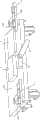
图1是本发明室内自主定位与定向的二维导航系统的硬件结构图。Fig. 1 is a hardware structure diagram of the indoor autonomous positioning and orientation two-dimensional navigation system of the present invention.
图1A是本发明室内自主定位与定向的二维导航系统的另一视角硬件结构图。FIG. 1A is another perspective hardware structure diagram of the indoor autonomous positioning and orientation two-dimensional navigation system of the present invention.
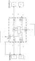
图2是本发明室内自主定位与定向的二维导航系统中DSP处理器的功能框图。Fig. 2 is a functional block diagram of the DSP processor in the indoor autonomous positioning and orientation two-dimensional navigation system of the present invention.
图3是本发明室内自主定位与定向的二维导航系统中定位解算的情景示意图。Fig. 3 is a schematic diagram of the positioning solution in the indoor autonomous positioning and orientation two-dimensional navigation system of the present invention.
图4是本发明室内自主定位与定向的二维导航系统的工作流程框图。Fig. 4 is a block diagram of the workflow of the indoor autonomous positioning and orientation two-dimensional navigation system of the present invention.
1.DSP数学信号处理器 101.当前位置坐标解算单元1. DSP
102.陀螺信息读取单元 103.转向舵机控制脉冲生成单元102. Gyro
104.左超声波触发脉冲生成单元 105.右超声波触发脉冲生成单元104. Left ultrasonic trigger
106.左超声波距离获取单元 107.右超声波距离获取单元106. Left ultrasonic
108.左扫描舵机控制脉冲生成单元 109.右扫描舵机控制脉冲生成单元108. Left scan servo control
110.超声波测距指向解析单元 2.MEMS陀螺传感器110. Ultrasonic ranging and
3.转向舵机 4.左超声波收发器 5.左扫描舵机3.
5A.左舵机本体 5B.左舵机摇臂 5C.左舵机转轴5A.
7.右超声波收发器 6.右扫描舵机 6A.右舵机本体7. Right
6B.右舵机摇臂 6C.右舵机转轴 10.运动载体6B. Right steering
具体实施方式Detailed ways
下面将结合附图对本发明做进一步的详细说明。The present invention will be further described in detail below in conjunction with the accompanying drawings.
参见图1、图1A所示,本发明的一种室内自主定位与定向的二维导航系统,其组成包括:DSP数字信号处理器1、MEMS陀螺传感器2、转向舵机3、左超声波收发器4、右超声波收发器7、左扫描舵机5和右扫描舵机6;其中:左扫描舵机5包括有左舵机本体5A、左舵机摇臂5B和左舵机转轴5C;左舵机摇臂5B为T形摇臂,左舵机摇臂5B的一端绕左舵机转轴5C旋转,左舵机摇臂5B安装在左舵机本体5A上。其中:右扫描舵机6包括有右舵机本体6A、右舵机摇臂6B和右舵机转轴6C;右舵机摇臂6B为T形摇臂,右舵机摇臂6B的一端绕右舵机转轴6C旋转,右舵机摇臂6B安装在右舵机本体6A上。Referring to Fig. 1, shown in Fig. 1A, a kind of indoor two-dimensional navigation system of autonomous positioning and orientation of the present invention, its composition comprises: DSP digital signal processor 1,
在本发明中,运动载体10的坐标系记为ob-xbybzb,也称为本体坐标系ob-xbybzb;坐标原点ob保持与运动载体10的几何中心重合,ob-xbybzb坐标系的xb轴沿运动载体的纵向轴向前,ob-xbybzb坐标系的yb轴沿运动载体的横向轴向左,ob-xbybzb坐标系的zb轴垂直于运动载体向上,与xb、yb构成右手坐标系。In the present invention,the coordinate system of the moving
所述的DSP数字信号处理器1安装在运动载体10上。The DSP digital signal processor 1 is installed on a moving
所述的MEMS陀螺传感器2安装在运动载体10上,且安装方位需要保证MEMS陀螺传感器2的三轴与运动载体10的坐标系ob-xbybzb的三轴分别重合。MEMS陀螺传感器2用于测量运动载体10在运动状态下的三轴角速率信息F21(ωbx,ωby,ωbz),ωbx表示在坐标系ob-xbybzb下绕xb轴转动的角速率分量,ωby表示在坐标系ob-xbybzb下绕yb轴转动的角速率分量,ωbz表示在坐标系ob-xbybzb下绕zb轴转动的角速率分量。The
所述的转向舵机3安装在运动载体10的前端,转向舵机摇臂31与运动载体10的转向机构相连;转向舵机3用于操纵运动载体10实现转向。The
所述的左超声波收发器4安装在左舵机摇臂5B上,且保证左超声波收发器4所发超声波波束的方向与左舵机摇臂5B的指向相同。左超声波收发器4根据收到的左超声波测距脉冲信号F14后发射出超声波,然后当左超声波收发器4收到回波后,则输出左距离脉冲信号F41给DSP数字信号处理器1。The left
所述的右超声波收发器7安装在右舵机摇臂6B上,且保证右超声波收发器7所发超声波波束的方向与右舵机摇臂6B的指向相同。右超声波收发器7根据收到的右超声波测距脉冲信号F17后发射出超声波,然后当右超声波收发器7收到回波后,则输出右距离脉冲信号F71给DSP数字信号处理器1。The right
所述的左舵机本体5A安装在运动载体10上,其安装方位需要保证在左舵机本体5A复位时(上电初始状态)左舵机摇臂5B的指向沿着运动载体10的纵向轴(即ob-xbybzb坐标系的xb轴)向前,且以后左舵机摇臂5B能向左旋转不受阻碍。为了便于定位解算,左舵机本体5A安装时同时保证左舵机转轴5C垂直于运动载体10的左上顶点AA。The left
所述的右舵机本体6A安装在运动载体10上,其安装方位需要保证在右舵机本体6A复位时(上电初始状态)右舵机摇臂6B的指向沿着运动载体10的纵向轴(ob-xbybzb坐标系的xb轴)向前,且以后右舵机摇臂6B能向右旋转不受阻碍。为了便于定位解算,右舵机本体6A安装时同时保证右舵机转轴6C垂直于运动载体10的右上顶点BB。The right
在本发明中,左超声波收发器4和左扫描舵机5组成左侧扫描测距单元;右超声波收发器7和右扫描舵机6组成右侧扫描测距单元(参见图2所示)。In the present invention, the left
本发明中,DSP数字信号处理器1选用AnalogDevices公司生产的ADSP-BF537处理器。MEMS陀螺传感器2选用InvenSense公司生产的ITG-3200陀螺仪。转向舵机3选用辉盛公司的Tower Pro 9805BB舵机,其舵机摇臂31选取原装的53.3mm直型摇臂。左扫描舵机5选用ESKY公司的EK2-0508型数字舵机,其左舵机摇臂5B选取原装的T形摇臂。右扫描舵机6选用ESKY公司的EK2-0508型数字舵机,其右舵机摇臂6B选取原装的T形摇臂。左超声波收发器4选用上海芯源(中国)电子有限公司生产的SRF05超声波传感器,其探测范围1cm~4m,精度可达3mm。右超声波收发器7选用上海芯源(中国)电子有限公司生产的SRF05超声波传感器,其探测范围1cm~4m,精度可达3mm。In the present invention, the DSP digital signal processor 1 selects the ADSP-BF537 processor produced by AnalogDevices Company.
参见图2所示,用于实现本发明室内自主定位与定向的二维导航系统的DSP数字信号处理器1,该DSP数字信号处理器1根据实现的功能包括有下列单元:当前位置坐标解算单元101、陀螺信息读取单元102、转向舵机控制脉冲生成单元103、左超声波触发脉冲生成单元104、左超声波距离获取单元106、右超声波触发脉冲生成单元105、右超声波距离获取单元107、左扫描舵机控制脉冲生成单元108、右扫描舵机控制脉冲生成单元109、超声波测距指向解析单元110。Referring to shown in Fig. 2, be used to realize the DSP digital signal processor 1 of the two-dimensional navigation system of indoor autonomous positioning and orientation of the present invention, this DSP digital signal processor 1 comprises following unit according to the function realized: current position coordinate
下面将详细说明在DSP数字信号处理器1上各个单元实现的功能:The functions realized by each unit on the DSP digital signal processor 1 will be described in detail below:
(1)陀螺信息读取单元102(1) Gyro
陀螺信息读取单元102第一方面用于读取MEMS陀螺传感器2测量得到的运动载体10在运动状态下的三轴角速率信息F21(ωbx,ωby,ωbz);第二方面对三轴角速率信息F21(ωbx,ωby,ωbz)中的绕zb轴转动的角速率分量ωbz进行初始时刻至当前时刻角速率分量的积分处理
在本发明中,用于确定运动载体10位置的坐标系称为导航坐标系O-xoyozo,导航坐标系O-xoyozo的坐标原点O与初始位置时的运动载体10的几何中心重合,xo沿初始位置时的运动载体10的纵向轴向前,yo沿初始位置时的运动载体10的横轴向左,zo垂直运动载体10向上,与xo、yo构成右手坐标系。In the present invention, the coordinate system used to determine the position of the moving
(2)转向舵机控制脉冲生成单元103(2) Steering servo control
转向舵机控制脉冲生成单元103第一方面用于产生控制转向舵机3的脉冲信号F13(简称为转向舵机脉冲信号F13);第二方面以转向舵机脉冲宽度变量F31控制转向舵机脉冲信号F13的脉冲宽度WF13(简称为转向舵机脉冲宽度WF13),且
在本发明中,转向舵机控制脉冲信号F13是周期为19.2ms的方波。In the present invention, the steering steering gear control pulse signal F13 is a square wave with a period of 19.2ms.
(3)左超声波触发脉冲生成单元104(3) left ultrasonic trigger
左超声波触发脉冲生成单元104用于产生左超声波测距脉冲信号F14,该左超声波测距脉冲信号F14是一个脉冲宽度为10μs的单束脉冲。The left ultrasonic trigger
在本发明中,左超声波收发器4收到左超声波测距脉冲信号F14后发射出超声波,当左超声波收发器4收到回波时,则向左超声波距离获取单元106输出左距离脉冲信号F41。In the present invention, the left
(4)左超声波距离获取单元106(4) left ultrasonic
左超声波距离获取单元106第一方面接收左距离脉冲信号F41;第二方面对左距离脉冲信号F41进行脉冲宽度测量得到左距离脉冲宽度WF41;第三方面依据脉冲宽度与到障碍面距离的关系
(5)右超声波触发脉冲生成单元105(5) Right ultrasonic trigger
右超声波触发脉冲生成单元105用于产生右超声波测距脉冲信号F17,该右超声波测距脉冲信号F17是一个脉冲宽度为10μs的单束脉冲。The right ultrasonic trigger
在本发明中,右超声波收发器7收到右超声波测距脉冲信号F17后发射出超声波,当右超声波收发器7收到回波时,则向右超声波距离获取单元107输出右距离脉冲信号F71。In the present invention, the right
(6)右超声波距离获取单元107(6) Right ultrasonic
右超声波距离获取单元107第一方面接收右距离脉冲信号F71;第二方面对右距离脉冲信号F71进行脉冲宽度测量得到右距离脉冲宽度WF71;第三方面依据脉冲宽度与到障碍面距离的关系
(7)超声波测距指向解析单元110(7) Ultrasonic ranging and
超声波测距指向解析单元110第一方面用于产生左扫描舵机脉冲宽度变量F61,该左扫描舵机脉冲宽度变量F61用于调节左舵机控制脉冲信号F16的脉冲宽度WF16(简称为左舵机脉冲宽度WF16),该左舵机脉冲宽度WF16与左扫描舵机脉冲宽度变量F61之间满足
超声波测距指向解析单元110第二方面依据左舵机脉冲宽度WF16与左舵机摇臂5B的偏转角度α之间的关系
超声波测距指向解析单元110第三方面用于产生右扫描舵机脉冲宽度变量F91,该右扫描舵机脉冲宽度变量F91用于控制右舵机脉冲信号F19的脉冲宽度WF19(简称为右舵机脉冲宽度WF19);该右舵机脉冲宽度WF19与右扫描舵机脉冲宽度变量F91之间满足
超声波测距指向解析单元110第四方面依据右舵机脉冲宽度WF19与右舵机摇臂6B的偏转角度β之间的关系
在本发明中,左、右舵机控制脉冲信号F16、F19的脉冲宽度WF16、WF19的单位为秒;左、右偏转角度α、β的单位为度。In the present invention, the unit of the pulse widths WF16 and WF19 of the left and right servo control pulse signals F16 and F19 is second; the unit of the left and right deflection angles α and β is degree.
在本发明中,通过改变输出的左舵机控制脉冲信号F16的脉冲宽度WF16能够改变左舵机摇臂5B的偏转角度α;通过改变输出的右舵机控制脉冲信号F19的脉冲宽度WF19能够改变右舵机摇臂6B的偏转角度β;利用改变偏转角度α对固联在左舵机摇臂5B上的左超声波收发器4的指向进行实时可控调节;利用改变偏转角度β对固联在右舵机摇臂6B上的右超声波收发器7的指向进行实时可控调节。In the present invention, the deflection angle α of the rocking arm5B of the left steering gear can be changed by changing the pulse width WF16 of the left steering gear control pulse signal F 16 of output; by changing the pulse width of the right steering gear control pulse signal F19 of output WF19 can change the deflection angle β of the right steering
在本发明中,超声波测距指向解析单元110连续地增加或减小左舵机脉冲宽度WF16和右舵机脉冲宽度WF19,左偏转角度α和右偏转角度β将连续改变,从而实现两个超声波收发器的扫描测距。当超声波测距指向解析单元110不改变左舵机脉冲宽度WF16和右舵机脉冲宽度WF19,则左偏转角度α和右偏转角度β将固定不变,从而实现两个超声波收发器的定向测距。In the present invention, the ultrasonic ranging and
(8)左扫描舵机控制脉冲生成单元108(8) left scanning servo control
左扫描舵机控制脉冲生成单元108用于生成控制左扫描舵机5转动的脉冲信号F16(简称为左舵机控制脉冲信号F16)。The left scanning steering gear control
左舵机控制脉冲信号F16是周期为19.2ms的方波。The left servo control pulse signal F16 is a square wave with a period of 19.2ms.
(9)右扫描舵机控制脉冲生成单元109(9) right scanning servo control
右扫描舵机控制脉冲生成单元109用于生成控制右扫描舵机6转动的脉冲信号F19(简称为右舵机控制脉冲信号F19)。The right scanning steering gear control
右舵机控制脉冲信号F19是周期为19.2ms的方波。The right servo control pulse signal F19 is a square wave with a period of 19.2ms.
(10)当前位置坐标解算单元101(参见图3所示)(10) current position coordinate calculation unit 101 (see Fig. 3 )
在运动载体10的坐标系ob-xbybzb下,当运动载体10完成姿态初始化后xb轴与左侧障碍面平齐,定义此时的位置为初始位置,并以运动载体10的几何中心点建立了导航坐标系O-xoyozo。Under the coordinate system ob -xby yb zb of the moving
在初始位置时,左偏转角度记为α0,右偏转角度记为β0,左距离值记为m0,右距离值记为n0;At the initial position, the left deflection angle is recorded as α0 , the right deflection angle is recorded as β0 , the left distance value is recorded as m0 , and the right distance value is recorded as n0 ;
当运动载体10运动一个航向角θ后,依据运动载体在导航坐标系O-xoyozo下的位置更新矩阵When the moving
得到运动载体10的当前位置坐标
在本发明中,在已知运动载体相对于初始位置的偏转角度θ、左右超声波测距指向[α β]T和到障碍面的左右距离[m n]T后,通过上述运动载体10在导航坐标系O-xoyozo下的位置更新矩阵便能够计算出运动载体10的当前位置坐标,从而完成对运动载体10的定位。In the present invention, after knowing the deflection angle θ of the moving carrier relative to the initial position, the left and right ultrasonic ranging directions [α β]T , and the left and right distance [m n]T to the obstacle surface, the above moving
参见图4所示,采用本发明室内自主定位与定向的二维导航系统完成一次室内定位与定向的具体工作流程如下:Referring to Fig. 4, the specific workflow for completing an indoor positioning and orientation using the two-dimensional navigation system for indoor autonomous positioning and orientation of the present invention is as follows:
a)当运动载体10进入室内使用环境后,首先完成系统初始化,所有舵机(转向舵机3、左扫描舵机5、右扫描舵机6)复位;a) After the
b)通过超声波测距指向解析单元110连续改变左扫描舵机脉冲宽度变量F61,并由左扫描舵机控制脉冲生成单元108产生具有不同左舵机脉冲宽度WF16的左舵机控制脉冲信号F16,该左舵机控制脉冲信号F16用于驱动左扫描舵机5扫描;同时左超声波触发脉冲生成单元104产生左超声波测距脉冲信号F14,左侧扫描测距单元通过扫描测距搜索左侧障碍面;当左超声波收发器4收到回波时,超声波测距指向解析单元110不再左扫描舵机脉冲宽度变量F61,并计算此时的左偏转角度α;当左偏转角度α不等于90度时,启动转向舵机控制脉冲生成单元103调整转向舵机3的偏转角度,从而控制运动载体10偏转;b) The pulse width variable F61 of the left scanning steering gear is continuously changed by the ultrasonic ranging and
c)重复b)步骤,直至夹角α=90°结束循环。此时完成了运动载体10的姿态初始化,其
d)当运动载体10运动后,MEMS陀螺数据读取单元102读取MEMS陀螺传感器绕
e)超声波测距指向解析单元110连续改变左扫描舵机脉冲宽度变量F61,并由左扫描舵机控制脉冲生成单元108产生产生具有不同左舵机脉冲宽度WF16的左舵机控制脉冲信号F16,该左舵机控制脉冲信号F16用于驱动左扫描舵机5扫描;同时左超声波触发脉冲生成单元104产生左超声波测距脉冲信号F14,左侧扫描测距单元通过扫描测距搜索左侧障碍面;当左超声波收发器4收到回波时,超声波测距指向解析单元110不再左扫描舵机脉冲宽度变量F61,并计算此时的左偏转角度α;e) The ultrasonic ranging and
超声波测距指向解析单元110连续改变右扫描舵机脉冲宽度变量F91,并由右扫描舵机控制脉冲生成单元109产生产生具有不同右舵机脉冲宽度WF19的右舵机控制脉冲信号F19,该右舵机控制脉冲信号F19用于驱动右扫描舵机6扫描;同时右超声波触发脉冲生成单元105产生右超声波测距脉冲信号F17,右侧扫描测距单元通过扫描测距搜索右上侧障碍面;当右超声波收发器7收到回波时,超声波测距指向解析单元110不再右扫描舵机脉冲宽度变量F91,并计算此时的右偏转角度β;The ultrasonic ranging and
f)左超声波距离获取单元106依据脉冲宽度与到障碍面距离的关系
g)当前位置坐标解算单元101在获得载体相对于初始位置的偏转角度θ、左右超声波测距指向[α β]T和到障碍面的左右距离[m n]T后,利用位置更新矩阵计算并更新载体在导航坐标系下的位置坐标[X Y]T,从而完成一次自主定位和定向导航。g) Thecurrent positioncoordinate calculation unit 101 uses the position update matrix to calculate and Update the position coordinates [X Y]T of the carrier in the navigation coordinate system, so as to complete an autonomous positioning and directional navigation.
Claims (9)


Priority Applications (1)
| Application Number | Priority Date | Filing Date | Title |
|---|---|---|---|
| CN 201110256305CN102436260B (en) | 2011-09-01 | 2011-09-01 | Indoor self-positioning and self-directing two-dimensional navigation system |
Applications Claiming Priority (1)
| Application Number | Priority Date | Filing Date | Title |
|---|---|---|---|
| CN 201110256305CN102436260B (en) | 2011-09-01 | 2011-09-01 | Indoor self-positioning and self-directing two-dimensional navigation system |
Publications (2)
| Publication Number | Publication Date |
|---|---|
| CN102436260A CN102436260A (en) | 2012-05-02 |
| CN102436260Btrue CN102436260B (en) | 2013-07-24 |
Family
ID=45984362
Family Applications (1)
| Application Number | Title | Priority Date | Filing Date |
|---|---|---|---|
| CN 201110256305Expired - Fee RelatedCN102436260B (en) | 2011-09-01 | 2011-09-01 | Indoor self-positioning and self-directing two-dimensional navigation system |
Country Status (1)
| Country | Link |
|---|---|
| CN (1) | CN102436260B (en) |
Families Citing this family (8)
| Publication number | Priority date | Publication date | Assignee | Title |
|---|---|---|---|---|
| CN102789233B (en)* | 2012-06-12 | 2016-03-09 | 湖北三江航天红峰控制有限公司 | The integrated navigation robot of view-based access control model and air navigation aid |
| CN103791898A (en)* | 2012-10-30 | 2014-05-14 | 联想(北京)有限公司 | Method and electronic equipment for navigation in building |
| CN103914067A (en)* | 2013-01-05 | 2014-07-09 | 联想(北京)有限公司 | Control method and electronic equipment |
| CN106323284A (en)* | 2015-06-30 | 2017-01-11 | 上海慧流云计算科技有限公司 | Indoor positioning system and method based on path set and coordinate system |
| CN105606101B (en)* | 2015-12-21 | 2018-07-17 | 北京航天科工世纪卫星科技有限公司 | A kind of robot indoor navigation method based on ultrasonic measurement |
| CN111374776B (en)* | 2018-12-29 | 2024-09-03 | 达科为(深圳)医疗设备有限公司 | Surgical robot equipment with determinable position coordinates and surgical robot system |
| CN111257887B (en)* | 2020-02-17 | 2021-06-15 | 自然资源部第一海洋研究所 | Underwater instrument attitude detection system and detection method thereof |
| CN113660724B (en)* | 2021-10-20 | 2021-12-31 | 北京卓建智菡科技有限公司 | Motion trajectory determination method and device, computer equipment and storage medium |
Citations (4)
| Publication number | Priority date | Publication date | Assignee | Title |
|---|---|---|---|---|
| US6459990B1 (en)* | 1999-09-23 | 2002-10-01 | American Gnc Corporation | Self-contained positioning method and system thereof for water and land vehicles |
| WO2005119290A1 (en)* | 2004-05-17 | 2005-12-15 | Csi Wireless Inc. | Satellite position and heading sensor for vehicle steering control |
| CN2767963Y (en)* | 2004-08-16 | 2006-03-29 | 华南理工大学 | Minitype six-degree-of-freedom strapdown inertial navigation system based on microelectronic mechanical system component |
| CN101881619A (en)* | 2010-06-25 | 2010-11-10 | 哈尔滨工程大学 | Marine Strapdown Inertial Navigation and Astronomical Positioning Method Based on Attitude Measurement |
- 2011
- 2011-09-01CNCN 201110256305patent/CN102436260B/ennot_activeExpired - Fee Related
Patent Citations (4)
| Publication number | Priority date | Publication date | Assignee | Title |
|---|---|---|---|---|
| US6459990B1 (en)* | 1999-09-23 | 2002-10-01 | American Gnc Corporation | Self-contained positioning method and system thereof for water and land vehicles |
| WO2005119290A1 (en)* | 2004-05-17 | 2005-12-15 | Csi Wireless Inc. | Satellite position and heading sensor for vehicle steering control |
| CN2767963Y (en)* | 2004-08-16 | 2006-03-29 | 华南理工大学 | Minitype six-degree-of-freedom strapdown inertial navigation system based on microelectronic mechanical system component |
| CN101881619A (en)* | 2010-06-25 | 2010-11-10 | 哈尔滨工程大学 | Marine Strapdown Inertial Navigation and Astronomical Positioning Method Based on Attitude Measurement |
Non-Patent Citations (2)
| Title |
|---|
| 基于星间测量的卫星星座自主导航算法;陈培等;《北京航空航天大学学报》;20080229;第34卷(第2期);全文* |
| 陈培等.基于星间测量的卫星星座自主导航算法.《北京航空航天大学学报》.2008,第34卷(第2期), |
Also Published As
| Publication number | Publication date |
|---|---|
| CN102436260A (en) | 2012-05-02 |
Similar Documents
| Publication | Publication Date | Title |
|---|---|---|
| CN102436260B (en) | Indoor self-positioning and self-directing two-dimensional navigation system | |
| CN105157697B (en) | Indoor mobile robot pose measurement system and measurement method based on optoelectronic scanning | |
| US10520950B2 (en) | Self-moving robot movement boundary delimiting method | |
| CN105547305B (en) | A kind of pose calculation method based on wireless location and laser map match | |
| CN103477185B (en) | For the measuring system for the 3D coordinates for determining subject surface | |
| CN108919825A (en) | The unmanned plane indoor locating system and method for having barrier avoiding function | |
| CN103760517B (en) | Underground scanning satellite high-precision method for tracking and positioning and device | |
| CN111465908B (en) | Sectional type autonomous charging docking method, mobile device and charging station | |
| CN103363988A (en) | Method for realizing geomagnetic indoor positioning and navigation by utilization of smartphone sensors | |
| CN101762273A (en) | Autonomous optical navigation method for soft landing for deep space probe | |
| CN108844543A (en) | Indoor AGV navigation control method based on UWB positioning and dead reckoning | |
| CN104777452B (en) | Positioning system and positioning method of mobile equipment | |
| CN103434609A (en) | Automatic marking device for ship hull section outer plate | |
| CN102322857A (en) | Position and posture measuring system and method for mechanical equipment | |
| CN105445774A (en) | GNSS and laser range finding combination measurement system and method | |
| CN107179538A (en) | A kind of method and system of panoramic limit ultrasonic wave positioning distance measuring | |
| CN116132917B (en) | Indoor positioning device and method for long and narrow space | |
| CN103968830A (en) | Multi-way guiding device and multi-way guiding method for near-surface tracking of mother ship in navigation by UUV (Unmanned Underwater Vehicle) | |
| CN109631862A (en) | A kind of multi-Sensor Information Fusion Approach of intertidal zone integration mapping | |
| CN101858977A (en) | Indoor Space Positioning Method and System Based on Dual Infrared System | |
| KR101155500B1 (en) | Apparatus and method for controlling a plurality of moving bodies | |
| CN109029423A (en) | Substation's indoor mobile robot navigation positioning system and its navigation locating method | |
| CN104898146A (en) | Vehicle-mounted positioning device | |
| CN108332749B (en) | Indoor dynamic tracking and positioning method | |
| CN208854616U (en) | A SLAM-based Binocular Vision Dynamic Obstacle Avoidance Wheeled Robot |
Legal Events
| Date | Code | Title | Description |
|---|---|---|---|
| C06 | Publication | ||
| PB01 | Publication | ||
| C10 | Entry into substantive examination | ||
| SE01 | Entry into force of request for substantive examination | ||
| C14 | Grant of patent or utility model | ||
| GR01 | Patent grant | ||
| CF01 | Termination of patent right due to non-payment of annual fee | Granted publication date:20130724 Termination date:20140901 | |
| EXPY | Termination of patent right or utility model |