CN102435775A - Strain type three-dimensional acceleration sensor - Google Patents
Strain type three-dimensional acceleration sensorDownload PDFInfo
- Publication number
- CN102435775A CN102435775ACN2011102830516ACN201110283051ACN102435775ACN 102435775 ACN102435775 ACN 102435775ACN 2011102830516 ACN2011102830516 ACN 2011102830516ACN 201110283051 ACN201110283051 ACN 201110283051ACN 102435775 ACN102435775 ACN 102435775A
- Authority
- CN
- China
- Prior art keywords
- foil gauge
- operational amplifier
- strain gauge
- fixed value
- connected node
- Prior art date
- Legal status (The legal status is an assumption and is not a legal conclusion. Google has not performed a legal analysis and makes no representation as to the accuracy of the status listed.)
- Granted
Links
Images


Landscapes
- Measurement Of Length, Angles, Or The Like Using Electric Or Magnetic Means (AREA)
Abstract
Translated fromChineseDescription
Translated fromChinese技术领域technical field
本发明涉及一种应变式传感器,尤其是一种应变式三维加速度传感器。The invention relates to a strain sensor, in particular to a strain three-dimensional acceleration sensor.
背景技术Background technique
目前的三维加速度传感器,根据三维信息是通过单惯性质量块还是多惯性质量块获取分为两种结构形式:合成式和一体化式。前者是通过将多个单向加速度传感器采用正交的方式合成在一起,一般每个方向加速度信息分别对应一个质量块;后者则是通过单惯性质量块完成对三个方向加速度的测量。三维加速度传感器在开始的一段时间主要是将多个单维加速度传感器集成在一起实现对三维信息的获取,由于三个质量块的存在,质心的不一致带来测量方面的误差,且由于多个单轴向传感器合成在一起,是的整个传感器的体积相对较大。因此目前三维加速度传感器向着一体化方向发展。The current three-dimensional acceleration sensors are divided into two structural forms according to whether the three-dimensional information is acquired through a single inertial mass block or multiple inertial mass blocks: composite type and integrated type. The former is to synthesize multiple unidirectional acceleration sensors in an orthogonal manner, and generally each direction of acceleration information corresponds to a mass block; the latter is to complete the measurement of acceleration in three directions through a single inertial mass block. In the beginning, the three-dimensional acceleration sensor mainly integrated multiple single-dimensional acceleration sensors to obtain three-dimensional information. Due to the existence of three mass blocks, the inconsistency of the center of mass brought measurement errors, and due to the existence of multiple single-dimensional acceleration sensors The axial sensors are combined together, so the volume of the whole sensor is relatively large. Therefore, the current three-dimensional acceleration sensor is developing in the direction of integration.
目前,对于一体化结构的三维加速度传感器的研究历史不长。而近年来,随着半导体微加工技术的发展,基于不同工作原理的三维加速度传感器纷纷推出,主要以压电式、压阻式、电容式为主。在结构设计上,有悬臂梁型、双梁型、四梁型、岛型等。在应变片的应用方面,日本提出了应变式全剪切三维加速度传感器,但是此种传感器加工精度要求比较高,制造工艺成本较高。At present, the research history of the three-dimensional acceleration sensor with integrated structure is not long. In recent years, with the development of semiconductor microprocessing technology, three-dimensional acceleration sensors based on different working principles have been introduced, mainly piezoelectric, piezoresistive, and capacitive. In terms of structural design, there are cantilever beam type, double beam type, four beam type, island type and so on. In terms of the application of strain gauges, Japan proposed a strain-type full-shear three-dimensional acceleration sensor, but this kind of sensor requires relatively high processing accuracy and high manufacturing process costs.
发明内容Contents of the invention
本发明的目的是提供一种成本较低的应变式三维加速度传感器,其可以同时实现物体三维振动状态检测。The object of the present invention is to provide a low-cost strain-type three-dimensional acceleration sensor, which can simultaneously realize the detection of the three-dimensional vibration state of an object.
为了实现上述目的,本发明提供了一种应变式三维加速度传感器,其特征在于:包括弹性体、固定胶、质量块和8个应变片,其中所述弹性体的轴向截面呈“┻”形,该弹性体的下端为轮辐结构,上端为圆柱体结构且其上端面由所述固定胶固定连接所述质量块; In order to achieve the above object, the present invention provides a strain-type three-dimensional acceleration sensor, which is characterized in that it includes an elastic body, a fixing glue, a mass block and 8 strain gauges, wherein the axial section of the elastic body is in the shape of "┻" , the lower end of the elastic body is a spoke structure, the upper end is a cylindrical structure and its upper end surface is fixedly connected to the mass block by the fixing glue;
在所述轮辐同一条线的辐条上对称设置有四个应变片:第一应变片和第三应变片设置于所述辐条的上表面,第二应变片和第四应变片设置于所述辐条的下表面,由该四个应变片的电阻变化来反映Z轴方向的加速度变化;在所述弹性体的圆柱体上周向均匀设置有四个应变片:第五应变片、第六应变片、第七应变片和第八应变片,其中由所述第五应变片、第六应变片的电阻变化来反映X轴方向的加速度变化,由所述第七应变片、第八应变片的电阻变化来反映Y轴方向的加速度变化。Four strain gauges are symmetrically arranged on the spokes of the same line of the spokes: the first strain gauge and the third strain gauge are arranged on the upper surface of the spokes, and the second strain gauges and the fourth strain gauges are arranged on the spokes The lower surface of the four strain gauges reflects the acceleration change in the Z-axis direction by the change of resistance of the four strain gauges; four strain gauges are evenly arranged on the cylinder of the elastic body: the fifth strain gauge, the sixth strain gauge , the seventh strain gauge and the eighth strain gauge, wherein the acceleration change in the X-axis direction is reflected by the resistance change of the fifth strain gauge and the sixth strain gauge, and the resistance of the seventh strain gauge and the eighth strain gauge Change to reflect the acceleration change in the Y-axis direction.
所述第一应变片、第二应变片、第三应变片和第四应变片构成全桥测量电路,第一稳压器连接所述第一应变片与第四应变片的连接节点,向所述全桥测量电路提供稳压电源,第一滑动电阻器连接所述第二应变片与第三应变片的连接节点,用于平衡初始调零,且由所述第一应变片与第二应变片的连接节点,所述第三应变片与第四应变片的连接节点输出Z轴方向加速度的电信号;The first strain gauge, the second strain gauge, the third strain gauge and the fourth strain gauge constitute a full-bridge measurement circuit, and the first voltage regulator connects the connection nodes of the first strain gauge and the fourth strain gauge to supply The full-bridge measurement circuit provides a regulated power supply, and the first sliding resistor connects the connection node of the second strain gauge and the third strain gauge to balance the initial zeroing, and the first strain gauge and the second strain gauge The connecting node of the sheet, the connecting node of the third strain gauge and the fourth strain gauge outputs an electrical signal of acceleration in the Z-axis direction;
所述第五应变片、第六应变片与第一定值电阻、第二定值电阻构成第一半桥测量电路,第二稳压器连接所述第五应变片与第一定值电阻的连接节点,向所述第一半桥测量电路提供稳压电源,第二滑动电阻器连接所述第六应变片与第二定值电阻的连接节点,用于平衡初始调零,且由所述第五应变片与第六应变片的连接节点、所述第一定值电阻与第二定值电阻的连接节点输出X轴方向加速度的电信号;The fifth strain gauge, the sixth strain gauge, the first fixed-value resistor, and the second fixed-value resistor constitute a first half-bridge measurement circuit, and the second voltage regulator is connected to the fifth strain gauge and the first fixed-value resistor. A connection node that provides a regulated power supply to the first half-bridge measurement circuit, and a second sliding resistor that connects the connection node between the sixth strain gauge and the second fixed-value resistor for balancing the initial zeroing, and is controlled by the The connection node between the fifth strain gauge and the sixth strain gauge, and the connection node between the first fixed-value resistor and the second fixed-value resistor output an electrical signal of acceleration in the X-axis direction;
所述第七应变片、第八应变片与第三定值电阻、第四定值电阻构成第二半桥测量电路,第三稳压器连接所述第七应变片与第三定值电阻的连接节点,向所述第二半桥测量电路提供稳压电源,第三滑动电阻器连接所述第八应变片与第四定值电阻的连接节点,用于平衡初始调零,且由所述第七应变片与第八应变片的连接节点、所述第三定值电阻与第四定值电阻的连接节点输出Y轴加速度的电信号。The seventh strain gauge, the eighth strain gauge, the third fixed-value resistor, and the fourth fixed-value resistor constitute a second half-bridge measurement circuit, and the third voltage regulator is connected to the seventh strain gauge and the third fixed-value resistor. A connection node that provides a regulated power supply to the second half-bridge measurement circuit, and a third sliding resistor that connects the connection node between the eighth strain gauge and the fourth fixed-value resistor for balancing initial zeroing, and is controlled by the The connection node of the seventh strain gauge and the eighth strain gauge, and the connection node of the third fixed-value resistor and the fourth fixed-value resistor output an electric signal of Y-axis acceleration.
所述第一应变片与第二应变片的连接节点、所述第三应变片与第四应变片的连接节点分别连接第一级运算放大器AD1的正负输入端,Z轴方向加速度的电信号由所述第一级运算放大器AD1前置差分放大,再经第二级运算放大器OPA1放大滤波处理后,传输给第三级电压跟随器OPB1进行隔离处理;The connection node between the first strain gauge and the second strain gauge, the connection node between the third strain gauge and the fourth strain gauge are respectively connected to the positive and negative input terminals of the first-stage operational amplifier AD1, and the electrical signal of the acceleration in the Z-axis direction The first-stage operational amplifier AD1 pre-differentially amplifies, and then after the second-stage operational amplifier OPA1 is amplified and filtered, it is transmitted to the third-stage voltage follower OPB1 for isolation processing;
所述第五应变片与第六应变片的连接节点、所述第一定值电阻与第二定值电阻的连接节点分别连接第一级运算放大器AD2的正负输入端,X轴方向加速度的电信号由所述第一级运算放大器AD2前置差分放大,再经第二级运算放大器OPA2放大滤波处理后,传输给第三级电压跟随器OPB2进行隔离处理;The connecting node of the fifth strain gauge and the sixth strain gauge, the connecting node of the first fixed-value resistor and the second fixed-value resistor are respectively connected to the positive and negative input terminals of the first-stage operational amplifier AD2, and the acceleration in the X-axis direction The electric signal is pre-differentially amplified by the first-stage operational amplifier AD2, and then transmitted to the third-stage voltage follower OPB2 for isolation processing after being amplified and filtered by the second-stage operational amplifier OPA2;
所述第七应变片与第八应变片的连接节点、所述第三定值电阻与第四定值电阻的连接节点分别连接第一级运算放大器AD3的正负输入端,Y轴方向加速度的电信号由所述第一级运算放大器AD3前置差分放大,再经第二级运算放大器OPA3放大滤波处理后,传输给第三级电压跟随器OPB3进行隔离处理;The connection node of the seventh strain gauge and the eighth strain gauge, the connection node of the third fixed-value resistor and the fourth fixed-value resistor are respectively connected to the positive and negative input terminals of the first-stage operational amplifier AD3, and the acceleration in the Y-axis direction The electric signal is pre-differentially amplified by the first-stage operational amplifier AD3, and then transmitted to the third-stage voltage follower OPB3 for isolation processing after being amplified and filtered by the second-stage operational amplifier OPA3;
且第一电源适配器分别向所述第一级运算放大器AD1、第二级运算放大器OPA1以及第三级电压跟随器OPB1提供电源;第二电源适配器分别向所述第一级运算放大器AD2、第二级运算放大器OPA2以及第三级电压跟随器OPB2提供电源;第三电源适配器分别向所述第一级运算放大器AD3、第二级运算放大器OPA3以及第三级电压跟随器OPB3提供电源。And the first power adapter provides power to the first-stage operational amplifier AD1, the second-stage operational amplifier OPA1, and the third-stage voltage follower OPB1 respectively; the second power adapter provides power to the first-stage operational amplifier AD2, the second The first-stage operational amplifier OPA2 and the third-stage voltage follower OPB2 provide power; the third power adapter provides power to the first-stage operational amplifier AD3, the second-stage operational amplifier OPA3 and the third-stage voltage follower OPB3 respectively.
综上所述,由于采用了上述技术方案,本发明的有益效果是:In summary, owing to adopting above-mentioned technical scheme, the beneficial effect of the present invention is:
1、本发明在三维方向分别设置应变片,采用一体式传感器即可实现物体三维振动状态检测,且由于采用应变片实现测量,成本较低;1. In the present invention, strain gauges are respectively arranged in the three-dimensional direction, and the three-dimensional vibration state detection of the object can be realized by using the integrated sensor, and the cost is low because the strain gauge is used to realize the measurement;
2、由于应变片的电阻变化很微弱,本发明将电阻变化信息转变成电信号,更加易于实际应用,且对微弱的电信号进行放大滤波等处理,即使应变片电阻变化很小,也可以检测到,提高了传感器的灵敏度,降低了量程;2. Since the resistance change of the strain gauge is very weak, the present invention converts the resistance change information into an electrical signal, which is easier for practical application, and performs amplification and filtering on the weak electrical signal, so that even if the resistance change of the strain gauge is small, it can also detect To improve the sensitivity of the sensor and reduce the range;
3、本传感器中只需要将相应的应变片设置在对应的位置即可,不要求较高的加工精度,降低了制造工艺成本。3. In this sensor, it is only necessary to set the corresponding strain gauges at the corresponding positions, and high processing precision is not required, which reduces the cost of the manufacturing process.
附图说明Description of drawings
本发明将通过例子并参照附图的方式说明,其中:The invention will be illustrated by way of example with reference to the accompanying drawings, in which:
图1是本发明的正视图;Fig. 1 is the front view of the present invention;
图2是图1的俯视图;Fig. 2 is the top view of Fig. 1;
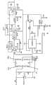
图3是用于调整Z轴方向加速度信号的电路图;Fig. 3 is a circuit diagram for adjusting the acceleration signal in the Z-axis direction;
图4是用于调整X轴方向加速度信号的电路图;Fig. 4 is a circuit diagram for adjusting the acceleration signal in the X-axis direction;
图5是用于调整Y轴方向加速度信号的电路图。Fig. 5 is a circuit diagram for adjusting the acceleration signal in the Y-axis direction.
具体实施方式Detailed ways
本说明书中公开的所有特征,或公开的所有方法或过程中的步骤,除了互相排斥的特征和/或步骤以外,均可以以任何方式组合。All features disclosed in this specification, or steps in all methods or processes disclosed, may be combined in any manner, except for mutually exclusive features and/or steps.
本说明书(包括任何附加权利要求、摘要和附图)中公开的任一特征,除非特别叙述,均可被其他等效或具有类似目的的替代特征加以替换。即,除非特别叙述,每个特征只是一系列等效或类似特征中的一个例子而已。Any feature disclosed in this specification (including any appended claims, abstract and drawings), unless expressly stated otherwise, may be replaced by alternative features which are equivalent or serve a similar purpose. That is, unless expressly stated otherwise, each feature is one example only of a series of equivalent or similar features.
该应变式三维加速度传感器包括弹性体1、固定胶3、质量块4和8个应变片。如图1所示,弹性体1的的轴向截面呈“┻”形,该弹性体1的下端为轮辐5的结构,上端为圆柱体6的结构且其上端面由固定胶3固定连接质量块4;在轮辐5的一条线的辐条上对称设置有四个应变片(即四个应变片与弹性体1的距离相等):第一应变片R1、第三应变片R3设置在辐条的上表面,第二应变片R2、第四应变片R4设置在辐条的下表面,且在弹性体1的圆柱体上周向均匀设置有四个应变片(即该四个应变片在同一圆周上,与轮辐5距离相等):第五应变片R5、第六应变片R6、第七应变片R7和第八应变片R8。贴在被测定物上的应变片,随着被测定物的应变一起伸缩,应变片的电阻也随之发生变化,因此可以由应变片电阻的变化来反映三维的加速度变化。本实施例中第一应变片R1、第二应变片R2、第三应变片R3和第四应变片R4的电阻变化来反映Z轴方向的加速度变化,第五应变片R5和第六应变片R6的变化来反映X轴方向的加速度变化,第七应变片R7和第八应变片R8的电阻变化来反映Y轴方向的加速度变化。The strain type three-dimensional acceleration sensor includes an
由于在测量过程中,应变片感受的应变很微弱,其电阻相对变化率△R/R很小,并且电阻变化信息不利于在实际中的应用,因此需要将电阻变化信息转换为电信号,且对该电信号进行放大处理。Since the strain felt by the strain gauge is very weak during the measurement process, its relative resistance change rate △R/R is very small, and the resistance change information is not conducive to practical application, so it is necessary to convert the resistance change information into an electrical signal, and The electrical signal is amplified.
如图3所示,在Z轴方向,第一应变片R1、第二应变片R2、第三应变片R3和第四应变片R4构成全桥测量电路,第一稳压器TL43-1连接第一应变片R1与第四应变片R4的连接节点a,其向该全桥测量电路提供5V的稳压电源,第一滑动电阻器RP1连接第二应变片R2与第三应变片R3的连接节点,实现对该全桥测量电路平衡初始调零。该全桥测量电路将Z轴方向应变片的电阻变化信息转换成Z轴方向加速度的电信号,由第一应变片R1与第二应变片R2的连接节点、第三应变片R3与第四应变片R4的连接节点输出给第一级运算放大器AD1的正反输入端,对电信号进行差分放大,有效地去除干扰,其中该第一级运算放大器AD1外接电阻R3-1,以将全桥测量电路输出的信号精确放大至确定的倍数,实现第一级电路的前置放大。As shown in Figure 3, in the Z-axis direction, the first strain gauge R1, the second strain gauge R2, the third strain gauge R3 and the fourth strain gauge R4 constitute a full-bridge measurement circuit, and the first voltage regulator TL43-1 is connected to the second The connection node a of a strain gauge R1 and the fourth strain gauge R4, which provides a 5V regulated power supply to the full-bridge measurement circuit, and the first sliding resistor RP1 connects the connection node of the second strain gauge R2 and the third strain gauge R3 , to realize the initial zeroing of the balance of the full-bridge measurement circuit. The full-bridge measurement circuit converts the resistance change information of the strain gauges in the Z-axis direction into electrical signals of the acceleration in the Z-axis direction, and is composed of the connection node between the first strain gauge R1 and the second strain gauge R2, the third strain gauge R3 and the fourth strain gauge The connection node of chip R4 is output to the positive and negative input terminals of the first-stage operational amplifier AD1, and differentially amplifies the electrical signal to effectively remove interference. The first-stage operational amplifier AD1 is connected with an external resistor R3-1 to measure the full-bridge The signal output by the circuit is accurately amplified to a certain multiple to realize the pre-amplification of the first stage circuit.
第一级运算放大器AD1的输出端通过电阻R4-1连接第二级运算放大器OPA1的正输入端,该第二级运算放大器OPA1的负输入端与接地的电阻R5连接,且第二级运算放大器OPA1与电阻R6-1、电容C3-1并联,其中经前置放大后的电信号通过电阻R4-1被精确放大至确定的倍数,且通过并联的电阻R6-1、电容C3-1实现低通滤波,从而实现了第二级电路的放大滤波。The output terminal of the first-stage operational amplifier AD1 is connected to the positive input terminal of the second-stage operational amplifier OPA1 through the resistor R4-1, and the negative input terminal of the second-stage operational amplifier OPA1 is connected to the grounded resistor R5, and the second-stage operational amplifier OPA1 is connected in parallel with resistor R6-1 and capacitor C3-1, in which the preamplified electrical signal is accurately amplified to a certain multiple through resistor R4-1, and the parallel connection of resistor R6-1 and capacitor C3-1 achieves low Pass filtering, thus realizing the amplification and filtering of the second stage circuit.
第二级运算放大器OPA1的输出端依次连接电阻R7-1、电容C6-1,且电容C6-1接地,电阻R7-1和电容C6-1的连接节点与第三跟随器OPB1连接,其中电阻R7-1和电容C6-1配置低通截止频率与上级一致,第三跟随器OPB1对电信号进行隔离、缓冲处理,提高输出阻抗,减少信号的衰减。由第三跟随器OPB1输出的电信号可以直接采用AD转换器进行模数转换处理。The output terminal of the second-stage operational amplifier OPA1 is connected to the resistor R7-1 and the capacitor C6-1 in turn, and the capacitor C6-1 is grounded, and the connection node of the resistor R7-1 and the capacitor C6-1 is connected to the third follower OPB1, wherein the resistor R7-1 and capacitor C6-1 configure the low-pass cut-off frequency to be consistent with that of the upper stage. The third follower OPB1 isolates and buffers the electrical signal to increase the output impedance and reduce signal attenuation. The electrical signal output by the third follower OPB1 can be directly processed by an AD converter for analog-to-digital conversion.
上述第一级运算放大器AD1、第二级运算放大器OPA1和第三跟随器OPB1均采用双电源供电方式,由第一电源适配器将220V电压转换为15V电压提供给三者,其中NE555-1可以将正电压转换成负电压,提高输出精度。The above-mentioned first-stage operational amplifier AD1, second-stage operational amplifier OPA1 and third follower OPB1 all adopt a dual-power supply mode, and the first power adapter converts 220V voltage into 15V voltage for the three, of which NE555-1 can Positive voltage is converted to negative voltage to improve output accuracy.
如图4所示,在X轴方向,第五应变片R5、第六应变片R6、第一定值电阻F1和第二定值电阻F2构成第一半桥测量电路,第二稳压器TL43-2连接第五应变片R5与第一定值电阻F1的连接节点a,其向该第一半桥测量电路提供5V的稳压电源,第二滑动电阻器RP2连接第六应变片R6与第二定值电阻F2的连接节点b,实现对该第一半桥测量电路平衡初始调零。该第一半桥测量电路将X轴方向应变片的电阻变化信息转换成X轴方向加速度的电信号,由第五应变片R5与第六应变片R6的连接节点c、第一定值电阻F1与第二定值电阻F2的连接节点d输出给第一级运算放大器AD2的正反输入端,对电信号进行差分放大,有效地去除干扰,其中该第一级运算放大器AD2外接电阻R3-2,以将全桥测量电路输出的信号精确放大至确定的倍数,实现第一级电路的前置放大。As shown in Figure 4, in the X-axis direction, the fifth strain gauge R5, the sixth strain gauge R6, the first fixed-value resistor F1 and the second fixed-value resistor F2 constitute the first half-bridge measurement circuit, and the second voltage regulator TL43 -2 connects the fifth strain gauge R5 and the connection node a of the first fixed-value resistor F1, which provides a 5V regulated power supply to the first half-bridge measurement circuit, and the second sliding resistor RP2 connects the sixth strain gauge R6 and the first fixed-value resistor F1 The connection node b of the two fixed-value resistors F2 realizes the initial zero adjustment of the balance of the first half-bridge measurement circuit. The first half-bridge measurement circuit converts the resistance change information of the strain gauges in the X-axis direction into electrical signals of acceleration in the X-axis direction, and the connection node c between the fifth strain gauge R5 and the sixth strain gauge R6, the first constant-value resistor F1 The connection node d with the second fixed-value resistor F2 is output to the positive and negative input terminals of the first-stage operational amplifier AD2 to differentially amplify the electrical signal and effectively remove interference, wherein the first-stage operational amplifier AD2 is externally connected to a resistor R3-2 , to accurately amplify the signal output by the full-bridge measurement circuit to a certain multiple, and realize the pre-amplification of the first-stage circuit.
第一级运算放大器AD2的输出端通过电阻R4-2连接第二级运算放大器OPA2的正输入端,该第二级运算放大器OPA2的负输入端与接地的电阻R5连接,且第二级运算放大器OPA2与电阻R6-2、电容C3-2并联,其中经前置放大后的电信号通过电阻R4-2被精确放大至确定的倍数,且通过并联的电阻R6-2、电容C3-2实现低通滤波,从而实现了第二级电路的放大滤波。The output terminal of the first-stage operational amplifier AD2 is connected to the positive input terminal of the second-stage operational amplifier OPA2 through the resistor R4-2, and the negative input terminal of the second-stage operational amplifier OPA2 is connected to the grounded resistor R5, and the second-stage operational amplifier OPA2 is connected in parallel with resistor R6-2 and capacitor C3-2, in which the preamplified electrical signal is accurately amplified to a certain multiple through resistor R4-2, and the parallel connection of resistor R6-2 and capacitor C3-2 achieves low Pass filtering, thus realizing the amplification and filtering of the second stage circuit.
第二级运算放大器OPA2的输出端依次连接电阻R7-2、电容C6-2,且电容C6-2接地,电阻R7-2和电容C6-2的连接节点与第三跟随器OPB2连接,其中电阻R7-2和电容C6-2配置低通截止频率与上级一致,第三跟随器OPB2对电信号进行隔离、缓冲处理,提高输出阻抗,减少信号的衰减。由第三跟随器OPB2输出的电信号可以直接采用AD转换器进行模数转换处理。The output terminal of the second-stage operational amplifier OPA2 is connected to the resistor R7-2 and the capacitor C6-2 in turn, and the capacitor C6-2 is grounded, and the connection node of the resistor R7-2 and the capacitor C6-2 is connected to the third follower OPB2, wherein the resistor R7-2 and capacitor C6-2 configure the low-pass cut-off frequency to be consistent with that of the upper stage, and the third follower OPB2 isolates and buffers the electrical signal to increase the output impedance and reduce signal attenuation. The electrical signal output by the third follower OPB2 can directly use an AD converter for analog-to-digital conversion processing.
上述第一级运算放大器AD2、第二级运算放大器OPA2和第三跟随器OPB2均采用双电源供电方式,由第二电源适配器将220V电压转换为15V电压提供给三者,其中NE555-1可以将正电压转换成负电压,提高输出精度。The above-mentioned first-stage operational amplifier AD2, second-stage operational amplifier OPA2 and third follower OPB2 all adopt dual power supply mode, and the second power adapter converts the 220V voltage into 15V voltage for the three, among which NE555-1 can Positive voltage is converted to negative voltage to improve output accuracy.
如图5所示,在Y轴方向,第七应变片R7、第八应变片R8、第三定值电阻F3和第四定值电阻F4构成第二半桥测量电路,第二稳压器TL43-3连接第七应变片R7与第三定值电阻F3的连接节点a,其向该第二半桥测量电路提供5V的稳压电源,第三滑动电阻器RP3连接第八应变片R8与第四定值电阻F4的连接节点b,实现对该第二半桥测量电路平衡初始调零。该第二半桥测量电路将Y轴方向应变片的电阻变化信息转换成Y轴方向加速度的电信号,由第七应变片R7与第八应变片R8的连接节点c、第三定值电阻F3与第四定值电阻F4的连接节点d输出给第一级运算放大器AD3的正反输入端,对电信号进行差分放大,有效地去除干扰,其中该第一级运算放大器AD3外接电阻R3-3,以将全桥测量电路输出的信号精确放大至确定的倍数,实现第一级电路的前置放大。As shown in Figure 5, in the Y-axis direction, the seventh strain gauge R7, the eighth strain gauge R8, the third fixed-value resistor F3 and the fourth fixed-value resistor F4 constitute the second half-bridge measurement circuit, and the second voltage regulator TL43 -3 connects the seventh strain gauge R7 and the connection node a of the third fixed-value resistor F3, which provides a 5V regulated power supply to the second half-bridge measurement circuit, and the third sliding resistor RP3 connects the eighth strain gauge R8 and the first fixed-value resistor F3 The connection node b of the four fixed-value resistors F4 realizes the initial zero adjustment of the balance of the second half-bridge measurement circuit. The second half-bridge measurement circuit converts the resistance change information of the strain gauges in the Y-axis direction into electrical signals of acceleration in the Y-axis direction. The connection node d with the fourth fixed-value resistor F4 is output to the positive and negative input terminals of the first-stage operational amplifier AD3 to differentially amplify the electrical signal and effectively remove interference, wherein the first-stage operational amplifier AD3 is externally connected to a resistor R3-3 , to accurately amplify the signal output by the full-bridge measurement circuit to a certain multiple, and realize the pre-amplification of the first-stage circuit.
第一级运算放大器AD3的输出端通过电阻R4-3连接第二级运算放大器OPA3的正输入端,该第二级运算放大器OPA3的负输入端与接地的电阻R5连接,且第二级运算放大器OPA3与电阻R6-3、电容C3-3并联,其中经前置放大后的电信号通过电阻R4-3被精确放大至确定的倍数,且通过并联的电阻R6-3、电容C3-3实现低通滤波,从而实现了第二级电路的放大滤波。The output terminal of the first-stage operational amplifier AD3 is connected to the positive input terminal of the second-stage operational amplifier OPA3 through the resistor R4-3, and the negative input terminal of the second-stage operational amplifier OPA3 is connected to the grounded resistor R5, and the second-stage operational amplifier OPA3 is connected in parallel with resistor R6-3 and capacitor C3-3, wherein the preamplified electrical signal is accurately amplified to a certain multiple through resistor R4-3, and the parallel connection of resistor R6-3 and capacitor C3-3 achieves low Pass filtering, thus realizing the amplification and filtering of the second stage circuit.
第二级运算放大器OPA3的输出端依次连接电阻R7-3、电容C6-3,且电容C6-3接地,电阻R7-3和电容C6-3的连接节点与第三跟随器OPB3连接,其中电阻R7-3和电容C6-3配置低通截止频率与上级一致,第三跟随器OPB3对电信号进行隔离、缓冲处理,提高输出阻抗,减少信号的衰减。由第三跟随器OPB3输出的电信号可以直接采用AD转换器进行模数转换处理。The output terminal of the second-stage operational amplifier OPA3 is connected to the resistor R7-3 and the capacitor C6-3 in turn, and the capacitor C6-3 is grounded, and the connection node of the resistor R7-3 and the capacitor C6-3 is connected to the third follower OPB3, wherein the resistor R7-3 and capacitor C6-3 configure the low-pass cut-off frequency to be consistent with that of the upper stage. The third follower OPB3 isolates and buffers the electrical signal to increase the output impedance and reduce signal attenuation. The electrical signal output by the third follower OPB3 can be directly processed by an AD converter for analog-to-digital conversion.
上述第一级运算放大器AD3、第二级运算放大器OPA3和第三跟随器OPB3均采用双电源供电方式,由第二电源适配器将220V电压转换为15V电压提供给三者,其中NE555-1可以将正电压转换成负电压,提高输出精度。The above-mentioned first-stage operational amplifier AD3, second-stage operational amplifier OPA3 and third follower OPB3 all adopt dual-power supply mode, and the second power adapter converts 220V voltage into 15V voltage for the three, among which NE555-1 can Positive voltage is converted to negative voltage to improve output accuracy.
本发明中应变式三维加速度传感器的工作原理为:The operating principle of the strain type three-dimensional acceleration sensor in the present invention is:
当被测物体以加速度运动时,质量块受到一个与加速度方向相反的惯性力作用,使弹性体产生变形,粘贴在弹性体上的应变片随之发生应变,从而使应变片的电阻发生变化。电阻的变化引起应变片组成的桥路出现不平衡,从而输出电压。应变片桥路不平衡而产生的输出电压与被测物体的加速度成线性关系,即可测得被测物体加速度的大小。When the measured object moves with acceleration, the mass block is subjected to an inertial force opposite to the direction of the acceleration, causing the elastic body to deform, and the strain gauge pasted on the elastic body will be strained accordingly, so that the resistance of the strain gauge will change. The change in resistance causes an imbalance in the bridge formed by the strain gauges, thereby outputting a voltage. The output voltage generated by the imbalance of the strain gauge bridge circuit has a linear relationship with the acceleration of the measured object, and the acceleration of the measured object can be measured.
该应变式三位加速度传感器通过选定应变片的布片位置,组成三个测量桥路,通过解耦后可以测量空间三个互相垂直方向上的加速度。The strain-type three-position acceleration sensor forms three measurement bridges by selecting the position of the strain gauge, and can measure the acceleration in three mutually perpendicular directions in space after decoupling.
本发明并不局限于前述的具体实施方式。本发明扩展到任何在本说明书中披露的新特征或任何新的组合,以及披露的任一新的方法或过程的步骤或任何新的组合。The present invention is not limited to the foregoing specific embodiments. The present invention extends to any new feature or any new combination disclosed in this specification, and any new method or process step or any new combination disclosed.
Claims (3)
Priority Applications (1)
| Application Number | Priority Date | Filing Date | Title |
|---|---|---|---|
| CN 201110283051CN102435775B (en) | 2011-09-22 | 2011-09-22 | Strain type three-dimensional acceleration sensor |
Applications Claiming Priority (1)
| Application Number | Priority Date | Filing Date | Title |
|---|---|---|---|
| CN 201110283051CN102435775B (en) | 2011-09-22 | 2011-09-22 | Strain type three-dimensional acceleration sensor |
Publications (2)
| Publication Number | Publication Date |
|---|---|
| CN102435775Atrue CN102435775A (en) | 2012-05-02 |
| CN102435775B CN102435775B (en) | 2013-03-06 |
Family
ID=45983936
Family Applications (1)
| Application Number | Title | Priority Date | Filing Date |
|---|---|---|---|
| CN 201110283051Expired - Fee RelatedCN102435775B (en) | 2011-09-22 | 2011-09-22 | Strain type three-dimensional acceleration sensor |
Country Status (1)
| Country | Link |
|---|---|
| CN (1) | CN102435775B (en) |
Cited By (10)
| Publication number | Priority date | Publication date | Assignee | Title |
|---|---|---|---|---|
| CN103018488A (en)* | 2012-12-06 | 2013-04-03 | 重庆大学 | Differential piezoelectric type three-dimensional acceleration sensor |
| CN103292939A (en)* | 2013-05-19 | 2013-09-11 | 吉林大学 | Spoke and central pin column combined type three-dimensional force sensor |
| CN103398807A (en)* | 2013-08-12 | 2013-11-20 | 中交第一公路工程局有限公司土木技术研究院 | Novel three dimensional stress measuring sensor |
| CN104970803A (en)* | 2015-07-08 | 2015-10-14 | 中国医学科学院生物医学工程研究所 | Probe with pulse blood oxygen detection and muscle relaxation detection function at same time |
| CN105891544A (en)* | 2016-04-27 | 2016-08-24 | 扬州大学 | Linear acceleration sensor for bionic-ear stone implement structure |
| CN106526233A (en)* | 2016-11-30 | 2017-03-22 | 中山市晶威电子科技有限公司 | Acceleration sensor |
| CN107807255A (en)* | 2017-10-19 | 2018-03-16 | 东南大学 | A kind of tunnel magnetoresistive formula accelerometer device based on micro hydraulic amplification |
| CN110006561A (en)* | 2019-05-10 | 2019-07-12 | 南京工程学院 | A device for measuring the force of a rolling pin in a screw nut by a stress ring method |
| CN113124747A (en)* | 2021-04-21 | 2021-07-16 | 齐鲁工业大学 | Three-dimensional sensor for online safety monitoring of asphalt pavement and preparation method thereof |
| JP7422114B2 (en) | 2021-09-07 | 2024-01-25 | 株式会社共和電業 | acceleration converter |
Citations (3)
| Publication number | Priority date | Publication date | Assignee | Title |
|---|---|---|---|---|
| US4372520A (en)* | 1981-08-13 | 1983-02-08 | Rockwell International Corporation | Suspension for three-axis accelerometer |
| US20070044557A1 (en)* | 2005-08-30 | 2007-03-01 | Takemasa Kengo | Package structure for an acceleration sensor |
| CN101819092A (en)* | 2010-03-25 | 2010-09-01 | 重庆大学 | Coupling type intelligent bearing monitoring device arranged on bearing |
- 2011
- 2011-09-22CNCN 201110283051patent/CN102435775B/ennot_activeExpired - Fee Related
Patent Citations (3)
| Publication number | Priority date | Publication date | Assignee | Title |
|---|---|---|---|---|
| US4372520A (en)* | 1981-08-13 | 1983-02-08 | Rockwell International Corporation | Suspension for three-axis accelerometer |
| US20070044557A1 (en)* | 2005-08-30 | 2007-03-01 | Takemasa Kengo | Package structure for an acceleration sensor |
| CN101819092A (en)* | 2010-03-25 | 2010-09-01 | 重庆大学 | Coupling type intelligent bearing monitoring device arranged on bearing |
Non-Patent Citations (1)
| Title |
|---|
| 王雅萍等: "一种三维加速度计弹性体的分析与设计", 《传感器与微系统》, vol. 25, no. 2, 31 December 2006 (2006-12-31)* |
Cited By (15)
| Publication number | Priority date | Publication date | Assignee | Title |
|---|---|---|---|---|
| CN103018488A (en)* | 2012-12-06 | 2013-04-03 | 重庆大学 | Differential piezoelectric type three-dimensional acceleration sensor |
| CN103292939A (en)* | 2013-05-19 | 2013-09-11 | 吉林大学 | Spoke and central pin column combined type three-dimensional force sensor |
| CN103398807A (en)* | 2013-08-12 | 2013-11-20 | 中交第一公路工程局有限公司土木技术研究院 | Novel three dimensional stress measuring sensor |
| CN103398807B (en)* | 2013-08-12 | 2016-04-20 | 中交一公局土木工程建筑研究院有限公司 | A kind of novel three-dimensional stress measurement sensor |
| CN104970803A (en)* | 2015-07-08 | 2015-10-14 | 中国医学科学院生物医学工程研究所 | Probe with pulse blood oxygen detection and muscle relaxation detection function at same time |
| CN105891544B (en)* | 2016-04-27 | 2018-11-09 | 扬州大学 | The linear acceleration sensor of imitative otolith device structure |
| CN105891544A (en)* | 2016-04-27 | 2016-08-24 | 扬州大学 | Linear acceleration sensor for bionic-ear stone implement structure |
| CN106526233A (en)* | 2016-11-30 | 2017-03-22 | 中山市晶威电子科技有限公司 | Acceleration sensor |
| CN106526233B (en)* | 2016-11-30 | 2023-04-21 | 中山市晶威电子科技有限公司 | Acceleration sensor |
| CN107807255A (en)* | 2017-10-19 | 2018-03-16 | 东南大学 | A kind of tunnel magnetoresistive formula accelerometer device based on micro hydraulic amplification |
| CN107807255B (en)* | 2017-10-19 | 2020-02-18 | 东南大学 | A Tunnel Magnetoresistive Accelerometer Device Based on Micro Hydraulic Amplification |
| CN110006561A (en)* | 2019-05-10 | 2019-07-12 | 南京工程学院 | A device for measuring the force of a rolling pin in a screw nut by a stress ring method |
| CN113124747A (en)* | 2021-04-21 | 2021-07-16 | 齐鲁工业大学 | Three-dimensional sensor for online safety monitoring of asphalt pavement and preparation method thereof |
| CN113124747B (en)* | 2021-04-21 | 2023-01-17 | 齐鲁工业大学 | Three-dimensional sensor for on-line safety monitoring of asphalt pavement and its preparation method |
| JP7422114B2 (en) | 2021-09-07 | 2024-01-25 | 株式会社共和電業 | acceleration converter |
Also Published As
| Publication number | Publication date |
|---|---|
| CN102435775B (en) | 2013-03-06 |
Similar Documents
| Publication | Publication Date | Title |
|---|---|---|
| CN102435775A (en) | Strain type three-dimensional acceleration sensor | |
| CN111633451B (en) | Three-dimensional force detection system of three-axis fast tool servo mechanism | |
| CN101419102B (en) | Ultra-thin six-dimensional force sensor and method for measuring three-dimensional force and three-dimensional torque information | |
| JP6966471B2 (en) | Coordinate measurement probe body | |
| CN103471751B (en) | High-precision strain type torque sensor | |
| CN105181193A (en) | Optical bragg grating six-dimension-force sensor, as well as main body structure and measurement method thereof | |
| WO2018120335A1 (en) | Capacitive sensor for absolute angular displacement measurement | |
| CN106124113A (en) | A kind of new six power and torque sensor | |
| CN103941041A (en) | Single-mass-block three-axis MEMS accelerometer with three frame structures | |
| CN101907502B (en) | Parallel-connection three-dimensional force sensor with decoupling structure | |
| CN205449351U (en) | Small -size three -dimensional force transducer | |
| CN102778583A (en) | Silicon substrate-based quartz resonance acceleration sensor chip with four-beam structure | |
| CN106969864B (en) | Double differential capacitance type moment sensor | |
| CN103737430B (en) | A kind of strain-type rotates two component Milling Force sensors | |
| CN107131986A (en) | A dual-hole parallel beam six-dimensional force sensor | |
| CN109781328B (en) | Six-dimensional force sensor with eight-beam structure | |
| Hsieh et al. | Investigation of a pressure sensor with temperature compensation using two concentric wheatstone-bridge circuits | |
| CN104316241A (en) | Small torque sensor | |
| CN101493473A (en) | Piezoelectric six-dimension acceleration sensor based on 6-SS parallel mechanism | |
| CN105841874B (en) | A kind of restructural type parallel connection multi-dimension force sensor | |
| CN114894364A (en) | Microminiature combined type multidimensional force sensor structure | |
| CN106771358A (en) | A kind of full quartz resonance accelerometer of miniature differential formula | |
| CN105841857A (en) | Parallel-type five-dimensional force sensor | |
| CN111964829B (en) | A six-dimensional force/torque measurement device | |
| CN101922942A (en) | Compensation Method for Axial Magnetic Field Sensitivity of Fiber Optic Gyroscope |
Legal Events
| Date | Code | Title | Description |
|---|---|---|---|
| C06 | Publication | ||
| PB01 | Publication | ||
| C10 | Entry into substantive examination | ||
| SE01 | Entry into force of request for substantive examination | ||
| C14 | Grant of patent or utility model | ||
| GR01 | Patent grant | ||
| CF01 | Termination of patent right due to non-payment of annual fee | ||
| CF01 | Termination of patent right due to non-payment of annual fee | Granted publication date:20130306 |