CN102434792A - High-brightness luminous light source - Google Patents
High-brightness luminous light sourceDownload PDFInfo
- Publication number
- CN102434792A CN102434792ACN201110231048XACN201110231048ACN102434792ACN 102434792 ACN102434792 ACN 102434792ACN 201110231048X ACN201110231048X ACN 201110231048XACN 201110231048 ACN201110231048 ACN 201110231048ACN 102434792 ACN102434792 ACN 102434792A
- Authority
- CN
- China
- Prior art keywords
- light source
- wavelength conversion
- excitation light
- medium layer
- conversion medium
- Prior art date
- Legal status (The legal status is an assumption and is not a legal conclusion. Google has not performed a legal analysis and makes no representation as to the accuracy of the status listed.)
- Pending
Links
- 230000005284excitationEffects0.000claimsdescription136
- 238000006243chemical reactionMethods0.000claimsdescription110
- 239000011248coating agentSubstances0.000claimsdescription26
- 238000000576coating methodMethods0.000claimsdescription26
- 238000000149argon plasma sinteringMethods0.000claimsdescription21
- 239000000758substrateSubstances0.000claimsdescription18
- 201000009310astigmatismDiseases0.000claimsdescription14
- 230000005540biological transmissionEffects0.000claimsdescription6
- 230000033001locomotionEffects0.000claims9
- OAICVXFJPJFONN-UHFFFAOYSA-NPhosphorusChemical compound[P]OAICVXFJPJFONN-UHFFFAOYSA-N0.000description19
- 238000010586diagramMethods0.000description16
- 230000003287optical effectEffects0.000description16
- 239000000843powderSubstances0.000description15
- 230000003595spectral effectEffects0.000description12
- 230000000694effectsEffects0.000description6
- 238000002834transmittanceMethods0.000description6
- 239000011521glassSubstances0.000description4
- 239000000084colloidal systemSubstances0.000description3
- 238000005516engineering processMethods0.000description3
- 238000004020luminiscence typeMethods0.000description3
- 238000005538encapsulationMethods0.000description2
- 238000001704evaporationMethods0.000description2
- 230000008020evaporationEffects0.000description2
- 239000010408filmSubstances0.000description2
- 238000000034methodMethods0.000description2
- 238000003672processing methodMethods0.000description2
- 238000004544sputter depositionMethods0.000description2
- 239000000126substanceSubstances0.000description2
- 230000032683agingEffects0.000description1
- 230000009286beneficial effectEffects0.000description1
- 230000008901benefitEffects0.000description1
- 238000003486chemical etchingMethods0.000description1
- 230000007423decreaseEffects0.000description1
- 230000007547defectEffects0.000description1
- 238000000605extractionMethods0.000description1
- 238000011049fillingMethods0.000description1
- 238000001914filtrationMethods0.000description1
- 238000010438heat treatmentMethods0.000description1
- 238000007731hot pressingMethods0.000description1
- 230000007246mechanismEffects0.000description1
- 238000012986modificationMethods0.000description1
- 230000004048modificationEffects0.000description1
- 239000012788optical filmSubstances0.000description1
- 239000002245particleSubstances0.000description1
- 230000005855radiationEffects0.000description1
- 238000002310reflectometryMethods0.000description1
- 238000005488sandblastingMethods0.000description1
- 239000007787solidSubstances0.000description1
- 238000001228spectrumMethods0.000description1
- 238000000411transmission spectrumMethods0.000description1
Images


Classifications
- G—PHYSICS
- G03—PHOTOGRAPHY; CINEMATOGRAPHY; ANALOGOUS TECHNIQUES USING WAVES OTHER THAN OPTICAL WAVES; ELECTROGRAPHY; HOLOGRAPHY
- G03B—APPARATUS OR ARRANGEMENTS FOR TAKING PHOTOGRAPHS OR FOR PROJECTING OR VIEWING THEM; APPARATUS OR ARRANGEMENTS EMPLOYING ANALOGOUS TECHNIQUES USING WAVES OTHER THAN OPTICAL WAVES; ACCESSORIES THEREFOR
- G03B21/00—Projectors or projection-type viewers; Accessories therefor
- G03B21/14—Details
- G03B21/20—Lamp housings
- G03B21/2006—Lamp housings characterised by the light source
- G03B21/2033—LED or laser light sources
- G03B21/204—LED or laser light sources using secondary light emission, e.g. luminescence or fluorescence
Landscapes
- Physics & Mathematics (AREA)
- Engineering & Computer Science (AREA)
- Multimedia (AREA)
- Optics & Photonics (AREA)
- General Physics & Mathematics (AREA)
- Non-Portable Lighting Devices Or Systems Thereof (AREA)
- Investigating, Analyzing Materials By Fluorescence Or Luminescence (AREA)
Abstract
Translated fromChineseDescription
Translated fromChinese技术领域technical field
本发明涉及固体光源,更为具体地说,涉及一种高亮度发光光源。The present invention relates to a solid-state light source, and more specifically, to a high-brightness light source.
背景技术Background technique
受激发光光源是一种固体光源,其通常是以激发光使得发光物质发出与激发光的波长不同的光线。受激发光光源包括常用的荧光光源,其通常使用LED发光或激光作为激发光,以荧光粉作为发光物质,通过使得LED发出的光或激光作用于荧光粉,使荧光粉发出荧光。以LED作为激发光的荧光光源为例,通常,可以将荧光粉涂敷与LED管芯表面上,并使用折射率匹配的胶体封装,这是现在市场上最常见的方法;还可以为了避免荧光粉受芯片加热而导致的效率下降和老化,将荧光粉均匀分布于LED封装胶体中;也可以将荧光粉层分布于封装胶体的外层,增加了发光均匀性;此外,还可以使用散射放射杯(diffuse reflection cup) 或透射型的二次光学机构以期提高光的萃取效率。但是,现有荧光粉技术中,荧光粉的激发效率都低于理论效率;由于荧光粉与相邻介质之间存在折射率差会产生部分激发光反射,或者由于荧光粉本身未能100%吸收照射的激发光因而反射部分激发光,造成激发光在入射到荧光粉时,必然会发生多次的发射和散射而不能完全入射到荧光粉层内部,直接被荧光粉反射/散射回去,这些被上述荧光粉表面反射或折射的激发光不能被利用,形成能量损失。Stimulated light source is a solid light source, which usually uses excitation light to make the luminescent substance emit light with a wavelength different from that of the excitation light. Stimulated light sources include commonly used fluorescent light sources, which usually use LED light or laser light as excitation light, and phosphor powder as a light-emitting substance. By making the light emitted by the LED or laser act on the phosphor powder, the phosphor powder emits fluorescence. Taking LED as the fluorescent light source for excitation light as an example, usually, phosphor powder can be coated on the surface of the LED tube core, and packaged with colloid with matching refractive index, which is the most common method in the market now; it can also be used to avoid fluorescent The efficiency decline and aging of the powder caused by the heating of the chip, the phosphor powder is evenly distributed in the LED encapsulation colloid; the phosphor layer can also be distributed on the outer layer of the encapsulation colloid, which increases the uniformity of light emission; in addition, scattering radiation can also be used Diffuse reflection cup or transmissive secondary optical mechanism in order to improve the light extraction efficiency. However, in the existing phosphor powder technology, the excitation efficiency of the phosphor powder is lower than the theoretical efficiency; due to the refractive index difference between the phosphor powder and the adjacent medium, there will be partial reflection of the excitation light, or because the phosphor powder itself cannot absorb 100% The irradiated excitation light thus reflects part of the excitation light, causing the excitation light to be emitted and scattered multiple times when it is incident on the phosphor powder, and cannot be completely incident inside the phosphor layer, and is directly reflected/scattered back by the phosphor powder. The excitation light reflected or refracted by the surface of the fluorescent powder cannot be utilized, resulting in energy loss.
发明内容Contents of the invention
本发明要解决的技术问题在于,针对现有技术的上述激发光利用效率较低缺陷,提供一种激发光利用效率较高的高亮度发光光源。The technical problem to be solved by the present invention is to provide a high-brightness luminescent light source with high excitation light utilization efficiency for the above-mentioned defect of low excitation light utilization efficiency in the prior art.
本发明提供一种高亮度发光光源,包括用于产生第一光线的第一光源以及用于消除第一光线相干性的散光层,还包括设置在第一光源与该散光层之间的第一滤光装置,第一滤光装置透射入射角小于第一特定角度的第一光线且反射入射角大于第一特定角度的第一光线。The present invention provides a high-brightness luminescent light source, which includes a first light source for generating first light and a scattering layer for eliminating the coherence of the first light, and also includes a first light source arranged between the first light source and the scattering layer. The filter device, the first filter device transmits the first light with an incident angle smaller than the first specific angle and reflects the first light with an incident angle larger than the first specific angle.
本发明还提供另一种高亮度发光光源,包括用于产生激发光的第一激发光源以及用于接收激发光并受激发出与该激发光波长不同的光的波长转换介质层,还包括设置在第一激发光源与波长转换介质层之间的第一滤光装置,第一滤光装置透射入射角小于第一特定角度的激发光且反射入射角大于第一特定角度的激发光。The present invention also provides another high-brightness luminescent light source, including a first excitation light source for generating excitation light and a wavelength conversion medium layer for receiving the excitation light and being excited to emit light with a wavelength different from that of the excitation light. The first filter device between the first excitation light source and the wavelength conversion medium layer, the first filter device transmits the excitation light with an incident angle smaller than the first specific angle and reflects the excitation light with an incident angle larger than the first specific angle.
与现有技术相比,本发明包括以下有益效果:由于在散光层/波长转换介质层之前设置有第一滤光装置,使得以较大入射角度进入散光层/波长转换介质层的第一光线/激发光会被反射,这样,当通过第一滤光装置的第一光线/激发光被散光层/波长转换介质层反射回第一滤光装置时,这些反射的第一光线/激发光的大部分会被第一滤光装置反射,再次进入上述散光层/波长转换介质层,从而,在总的光输入量一定的情况下,提高了激发光利用效率,具有光源亮度较大的优点。Compared with the prior art, the present invention includes the following beneficial effects: Since the first filter device is arranged before the scattering layer/wavelength conversion medium layer, the first light entering the scattering layer/wavelength conversion medium layer at a larger incident angle /exciting light will be reflected, so that when the first light/exciting light passing through the first optical filter device is reflected back to the first optical filtering device by the scattering layer/wavelength conversion medium layer, the first light/exciting light of these reflections Most of them will be reflected by the first filter device and enter the above-mentioned light scattering layer/wavelength conversion medium layer again, thus, when the total light input amount is constant, the utilization efficiency of excitation light is improved, and the light source has the advantage of greater brightness.
附图说明Description of drawings
图1是本发明实施例中高亮度发光光源的一个实施例的结构示意图。FIG. 1 is a schematic structural diagram of an embodiment of a high-brightness light source in an embodiment of the present invention.
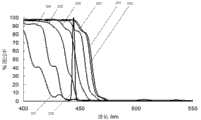
图2是图1所示实施例中对于不同的入射角和波长的光通过率示意图。FIG. 2 is a schematic diagram of light transmission rates for different incident angles and wavelengths in the embodiment shown in FIG. 1 .
图3是图1所示实施例中波长转换介质层对激发光的反射能量角分布示意图。Fig. 3 is a schematic diagram of the angular distribution of reflected energy of the excitation light by the wavelength conversion medium layer in the embodiment shown in Fig. 1 .
图4是图1所示实施例中使用的第一激发光源的光路示意图。Fig. 4 is a schematic diagram of the optical path of the first excitation light source used in the embodiment shown in Fig. 1 .
图5是本发明实施例中高亮度发光光源的另一实施例的结构示意图。Fig. 5 is a schematic structural diagram of another embodiment of a high-brightness light source in the embodiment of the present invention.
图6是本发明实施例中高亮度发光光源的另一实施例的结构示意图。Fig. 6 is a schematic structural diagram of another embodiment of a high-brightness light source in the embodiment of the present invention.
图7是本发明实施例中高亮度发光光源的另一实施例的结构示意图。Fig. 7 is a schematic structural diagram of another embodiment of a high-brightness light source in the embodiment of the present invention.
图8是本发明实施例中高亮度发光光源的另一实施例的结构示意图。Fig. 8 is a schematic structural diagram of another embodiment of a high-brightness light source in the embodiment of the present invention.
具体实施方式Detailed ways
下面将结合附图对本发明实施例作进一步说明。Below, the embodiments of the present invention will be further described in conjunction with the accompanying drawings.
图1是本发明实施例中高亮度发光光源的一个实施例的结构示意图,如图1所示,该光源包括用于发出激发光14的第一激发光源(图中未示出)、第一滤光装置11、波长转换介质层12、受激发光收集装置13等。在本实施例中,上述波长转换介质层12为荧光粉,而第一激发光源为激光光源,其在该高亮度发光光源中用于发出激发光14,该激发光14垂直于上述第一滤光装置11的光线通过该第一滤光装置11到达波长转换介质层。在本实施例中,调节上述第一激发光源的结构及其在该高亮度发光光源中的位置,使得该第一激发光源发出的激发光14尽可能多地垂直于上述第一滤光装置11或与上述第一滤光装置11的入射面法线方向的夹角尽可能小,从而使得尽可能多的激发光14通过上述第一滤光装置11到达上述波长转换介质层12。在上述激发光14到达上述波长转换介质层12后,一部分激发光14激发上述波长转换介质层12发出波长不同于激发光14的波长的光,而另一部分通过第一滤光装置11的激发光14被波长转换介质层12反射,在现有技术中,这部分被反射的激发光14是会逸出,不再作用于波长转换介质层12。因此,在现有技术中,这部分反射的激发光14对于受激发光是没有贡献的;但是,在本实施例中,由于上述第一滤光装置11的存在,上述被反射的激发光14中的绝大部分(这些反射光的绝大部分对于上述第一滤光装置11而言其入射角较大)不能通过上述第一滤光装置11;这些被反射的激发光14会被上述第一滤光装置11再次反射到上述波长转换介质层12上,其中一部分激发波长转换介质层12发出波长不同于激发光14的波长的光,另一部分被波长转换介质层12再次反射,然后再次被上述第一滤光装置11反射回来,如此反复,最后,只有极少部分的激发光14逸出。这样,在同样的激发光14的强度下,本实施例中的高亮度发光光源的发光效率较高、其亮度也较高。在本实施例中,上述第一滤光装置11同时可以反射波长转换介质层12受激产生的光。波长转换介质层的发光是各向同性的,其向背向于第一滤光装置11的一侧发出的受激发光15可以直接被受激发光收集装置13收集,而向另一侧发出的受激发光16则入射到第一滤光装置11上被反射至异侧而被受激发光收集装置13收集。这样第一滤光装置同时对受激发光起到了反射镜的作用,提高了收集效率。在本实施例中,上述激发光源是激光光源,在其他实施例中,该激发光源也可以是发光二极管(LED)光源。Fig. 1 is a schematic structural diagram of an embodiment of a high-brightness luminescent light source in an embodiment of the present invention. As shown in Fig. 1, the light source includes a first excitation light source (not shown in the figure) for
在图1所示的实施例中,激发光14为波长为440~450nm的蓝色激光,所述的第一滤光装置11使用一个干涉滤光片实现。当该激发光14以入射角度为0度~20度(即沿第一滤光装置11入射面法线方向或与入射面法线方向的夹角小于20度)入射时,其总透过率在90%左右;当入射角度为20度~40度时,其总透过率低于50%;当入射角度高于40度时,反射率高于90%。这样对于被荧光粉散射回来的大角度蓝光,可以被该滤光片再次反射回荧光粉进行二次激发。参见图2,图2是图1所示实施例中的干涉滤光片对于不同的入射角和波长的光通过率示意图,示出了在不同的入射角度下,不同波长的光透射通过上述第一滤光装置11的具体情况。图2的横轴表示入射光的光波长,其纵轴为入射光的透过率,图2中包括多条曲线,其中曲线201、曲线202、曲线203、曲线204、曲线205、曲线206、曲线207是入射角度为0、10、20、30、40、50、60度时,第一滤光装置11对不同波长的光的透射情况,而曲线208是第一滤光装置11对于符合上述条件的激发光的透射情况;从图中可以看出,基本上而言,上述440~450nm的蓝色激光在符合入射角度的情况下,可以几乎全部透射。这从一个侧面表示了在本实施例中选择蓝色激光的原因;若选用LED作为光源,其二次反射利用的原理是类似的,但由于其光谱宽度大于激光,其再利用的效率会比激光略低。In the embodiment shown in FIG. 1 , the
在本实施例中,激发光入射到荧光粉层上,有部分被反射回来。一个较为恰当的证明是图3,图3是图1所示实施例中波长转换介质层对激发光的反射能量角分布示意图。其横坐标是激发光的发射角度,纵坐标是归一化光能量。如图3,15度内的发射光占总反射光能量的30%多,也就是说使用了本发明,至少可以将其余将近70%的反射光能量再利用。In this embodiment, the excitation light is incident on the phosphor layer, and part of it is reflected back. A more appropriate proof is shown in FIG. 3 , which is a schematic diagram of the angular distribution of the reflected energy of the wavelength conversion medium layer to the excitation light in the embodiment shown in FIG. 1 . The abscissa is the emission angle of the excitation light, and the ordinate is the normalized light energy. As shown in Figure 3, the emitted light within 15 degrees accounts for more than 30% of the total reflected light energy, that is to say, using the present invention, at least the remaining nearly 70% of the reflected light energy can be reused.
据此,得知上述第一滤光装置11的特点是其存在一个第一特定角度,当入射光小于该角度时,其透射效果较好,如入射光大于该第一特定角度时,入射光通常将被反射。通常,根据上述第一滤光装置11的特点,上述第一特定角度小于45度。而在本实施例中,为了进一步提高效率,上述第一特定角度为15度,这样,使得小于上述第一特定角度的入射光透射的效果好。此外,在本实施例中,上述第一激发光源发出的光入射到波长转换介质层12的入射角小于45度。Accordingly, it is known that the above-mentioned
图4是图1所示实施例中使用的第一激发光源的光路示意图,该装置用于收集激发光并输出到荧光粉层,荧光粉放置于其右侧光线汇集的焦点处;可见其最大入射角度在15度左右,因此在使用上述滤光片时,保证了一次入射的透过率。当然,由于该滤光片对于小角度的激发光仍然有高透过率,因此反射/散射回来的激发光中的小角度部分依然会出射出来而形成损失。然而,这部分光在总反射光中所占的比例很小。以15度为例,其中的反射光能量占总反射光能量的比例约为30%。传统上,一般都会加大滤光装置的可入射角度,使得在同样的光照强度的情况下,尽可能地接受更多的入射光;但在本实施例中,提供了一种与传统的技术教导不一样的方向,即通过调整激发光源,使得激发光尽量集中于滤光装置的法线方向,同时,减小滤光装置的入射角度。在此情况下,反而得到较高亮度的发光光源。Fig. 4 is a schematic diagram of the optical path of the first excitation light source used in the embodiment shown in Fig. 1. The device is used to collect excitation light and output it to the phosphor layer. The incident angle is about 15 degrees, so when the above filter is used, the transmittance of one incident is guaranteed. Of course, since the filter still has a high transmittance for excitation light with a small angle, the small-angle part of the reflected/scattered excitation light will still go out and form a loss. However, this part of the light accounts for a small proportion of the total reflected light. Taking 15 degrees as an example, the reflected light energy accounts for about 30% of the total reflected light energy. Traditionally, the incident angle of the filter device is generally increased, so that under the same light intensity, more incident light can be accepted as much as possible; but in this embodiment, a technology different from the traditional technology is provided Teach different directions, that is, by adjusting the excitation light source, the excitation light is concentrated on the normal direction of the filter device as much as possible, and at the same time, the incident angle of the filter device is reduced. In this case, instead, a higher brightness light source is obtained.
在本实施例中,干涉滤光片实现了第一滤光装置的功能。而干涉滤光片往往采用蒸发或溅射的方式形成于一透明衬底(如玻璃)的表面,这个表面即具有预先设计的光谱特性(即透射入射角小于第一特定角度的激发光且反射入射角大于第一特定角度的激发光),在本文中,将该表面定义为第二镀膜面。在实际应用中,第二镀膜面面向所述波长转换介质层12会获得较好的效果。事实上,在任何情况下,第一滤光装置11到波长转换介质层12的距离越小,则光沿着垂直于光路的横向传播就越小,光能量就越集中,亮度越高,因此第二镀膜面到波长转换介质层12的距离越小越好,在实现上可以通过机械外力将第二镀膜面与波长转换介质层12压紧。In this embodiment, the interference filter realizes the function of the first filter device. The interference filter is often formed on the surface of a transparent substrate (such as glass) by evaporation or sputtering. This surface has pre-designed spectral characteristics (that is, the excitation light with an incident angle smaller than the first specific angle is transmitted and the reflection The excitation light whose incident angle is larger than the first specific angle), in this paper, this surface is defined as the second coating surface. In practical applications, better results will be obtained if the second coating surface faces the wavelength
上面描述了当该高亮度发光光源中存在波长转换介质层12的情况,实际上,在一些特定或特殊的场合下,也可能没有上述的波长转换介质层12,当激发光的波长就是所需要的波长的情况下,不可能在光源中设置波长转换介质层12。例如当激发光是蓝色激光,而需要的光也是蓝色光时,由于需要的蓝光不可能使用蓝色激光激发荧光粉产生,但可以使用蓝色激光自身。此时,由于激光是高度干涉光,如果直接使用,就会在屏幕上出现蓝色光点,并不能形成均匀视场。为了解决这个问题,可以在上述波长转换介质层12的位置将其用一个散光层(图中未示出)替代,该散光层包括散光膜或散光片,这样就可以打乱原有的激光相干性而实现均匀视场。而散光层必然会造成向后的散射,其对激光相干特性消除的越彻底,其反射率就越高,这样在本实施例中同样会起到蓝光自身增强的作用。这种情况下,高亮度发光光源包括用于产生第一光线的第一光源以及用于使第一光线消除其相干性的散光层,还包括设置在第一光源与该散光层之间的第一滤光装置,第一滤光装置透射入射角小于第一特定角度的第一光线且反射入射角大于第一特定角度的第一光线。显然,与图1所示实施例所不同的是,此处的第一光线可以不是激发光,事实上,图1所示实施例也可以不限定为激发光,此时波长转换介质层只起到散光层的作用,而不用于波长转换。一个较为恰当的例子是投影机中RGB三色光源中的蓝色光源。所以,在其他实施例中,也会出现上述波长转换介质层12被散光层代替的情况。此外,可以理解的是,在波长转换介质层被散光层代替的情况下,本发明中的受激发光收集装置也相应地被第一光线收集装置所代替。The above describes the situation when there is a wavelength
在本实施例中,上述第一滤光装置11和波长转换介质层12之间充有空气,这些空气在第一滤光装置11和波长转换介质层12之间形成一个空气层(air gap,图中未示出),该空气层的存在降低滤光装置设计和加工的难度,并提高了滤光装置的效果。同样,在本实施例中没有上述波长转换介质层12而是只有散光层的情况下,在上述第一滤光装置11和散光层之间同样存在上述空气层,其作用也大致与具有波长转换介质层12的情况大致相同。In this embodiment, air is filled between the above-mentioned
散光层主要有体散射和面散射两种,其加工方法有多样。例如面散射可以在玻璃衬底的背向激发光的表面上喷砂形成,或在该表面上用化学腐蚀的方法形成,也可以在塑料衬底上用热压成型的方法形成;对于体散射则可以使用在塑料衬底内部掺杂折射率不同的小颗粒形成散光层来散射光线。本发明并不限制散光层的种类和加工实现的方法。The astigmatism layer mainly includes volume scattering and surface scattering, and its processing methods are various. For example, surface scattering can be formed by sandblasting on the surface of the glass substrate facing away from the excitation light, or by chemical etching on the surface, or by hot pressing on the plastic substrate; for volume scattering Then, small particles with different refractive indices can be doped inside the plastic substrate to form a light-scattering layer to scatter light. The present invention does not limit the type and processing method of the light scattering layer.
同理,对于波长转换介质层被散光层代替的情况,第一滤光装置可以为干涉滤光片,该干涉滤光片可以包括第一镀膜面,该第一镀膜面透射入射角小于第一特定角度的第一光线且反射入射角大于第一特定角度的第一光线,该第一镀膜面面向散光层。Similarly, for the case where the wavelength conversion medium layer is replaced by a light-scattering layer, the first filter device can be an interference filter, and the interference filter can include a first coating surface, and the transmission incident angle of the first coating surface is smaller than the first The first light of a specific angle is reflected and the first light of an incident angle greater than the first specific angle is reflected, and the surface of the first coating film faces the light-scattering layer.
对于波长转换介质层被散光层代替的情况,面散射散光层相对于体散射散光层具有更高的效率。一个优选的方案是,面散射散光层包括一散射面,该散射面面向所述第一滤光装置,更为优选地,该散射面面向上述干涉滤光片的第一镀膜面,且该散射面与第一镀膜面之间的间距越小越好,在实现上也可以通过机械外力将第一镀膜面与该散射面压紧。而散光层的厚度对光的横向传播也有影响:厚度越大,横向传播越明显,光斑扩散越大,因此散光层的厚度也是越小越好。在该优选方案中,面散射散光层的厚度小于1 mm。For the case where the wavelength conversion medium layer is replaced by a light-scattering layer, the surface scattering light-scattering layer has higher efficiency than the volume-scattering light-scattering layer. A preferred solution is that the surface scattering astigmatism layer includes a scattering surface, and the scattering surface faces the first filter device, more preferably, the scattering surface faces the first coating surface of the above-mentioned interference filter, and the scattering surface The smaller the distance between the surface and the first coating surface, the better. In terms of realization, the first coating surface and the scattering surface can also be pressed tightly by mechanical external force. The thickness of the astigmatism layer also affects the lateral propagation of light: the greater the thickness, the more obvious the lateral propagation and the greater the spread of the spot, so the smaller the thickness of the astigmatism layer, the better. In this preferred solution, the thickness of the surface scattering layer is less than 1 mm.
对于波长转换介质层被散光层代替的情况,散光层还可以与第一滤光装置合二为一成为一个整体。例如,第一滤光装置可以设置于一衬底的面向激发光的一面上,散光层可以设置或形成于该衬底的背向激发光的一面上,散光层也可以形成于该衬底的内部。例如,衬底的面向激发光14的一面可以以镀光学薄膜的形式实现第一滤光装置11的作用,衬底的背向激发光的一面可以与散光层粘连在一起,或散光层直接加工形成于衬底的背向激发光的这一面上,或散光层直接加工形成于衬底的内部,此处的衬底可以为玻璃衬底或塑料衬底。For the case where the wavelength conversion medium layer is replaced by a light-scattering layer, the light-scattering layer can also be combined with the first filter device to form a whole. For example, the first filter device can be arranged on the side of a substrate facing the excitation light, the light scattering layer can be arranged or formed on the side of the substrate facing away from the excitation light, and the light scattering layer can also be formed on the side of the substrate internal. For example, the side of the substrate facing the
图5是本发明实施例中高亮度发光光源的另一实施例的结构示意图,在图5中,该高亮度发光光源包括第一激发光源(图中未示出)、第一滤光装置21、波长转换介质层22、分光滤光片26、反光镜27以及受激发光收集装置23。其中,第一激发光源发出的激发光24通过第一滤光装置21传送到波长转换介质层22,激发波长转换介质层22发出荧光25,这些荧光25被位于上述波长转换介质层22另一侧的反光镜27反射之后,再经过上述分光滤光片26反射到受激发光收集装置23,作为该受激发光光源的输出。在本实施例中,上述第一滤光装置21设置在波长转换介质层22的一端(与激发光24的入射方向为同一侧),而反光镜27位于上述波长转换介质层22的另一侧,即反光镜27设置在波长转换介质层22背向于第一滤光装置21的一侧,可大致平行于上述波长转换介质层22,用于将受激发光25反射向异侧而收集;而上述分光滤光片26设置在上述第一滤光装置21远离于波长转换介质层的一侧(即位于上述第一激发光源与第一滤光装置21之间),上述分光滤光片26的反光面靠近第一滤光装置21,分光滤光片26的入射面与第一滤光装置21入射面的法线的夹角大致为45度,便于将受激发光的光线导入上述受激发光收集装置23。在本实施例中,第一滤光装置21可以透射所述的波长转换介质层的发光,使得其直接的发光和由所述反射镜27反射回来的激发光从第一滤光装置21这一侧出射,经由分光滤光片26导入收集装置23。 Fig. 5 is a schematic structural diagram of another embodiment of a high-brightness light source in the embodiment of the present invention. In Fig. 5, the high-brightness light source includes a first excitation light source (not shown in the figure), a
在本实施例中,上述波长转换介质层22与第一滤光装置21和反光镜27之间也分别充有空气,这些空气也如同第一实施例中所描述的一样分别形成空气层,这些空气层的作用于第一实施例中所描述的大致相同。波长转换介质层22与反光镜27之间也可以没有空气填充,也就是波长转换介质层直接粘附于反光镜27表面上,这样反光镜同时可以起到帮助波长转换介质层散热的作用。In this embodiment, the above-mentioned wavelength
在本实施例中,与第一实施例相近的,波长转换介质层22与第一滤光装置21和反光镜27之间的距离越小越好。优选地,反光镜27的反射面面向波长转换介质层22,并可通过机械外力将该反射面与波长转换介质层压紧,使两者之间的距离尽量小。In this embodiment, similar to the first embodiment, the distance between the wavelength
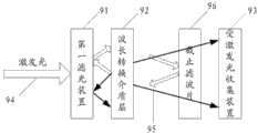
图6是本发明实施例中高亮度发光光源的另一实施例的结构示意图。如图6所示,本实施例的基本结构与第一实施例中大致相似,其包括了激发光94入射至的第一滤光装置91,波长转换介质层92、收集上述波长转换介质层92发出的受激发光95的受激发光收集装置93;上述各部件与第一实施例中各同名部件的作用及其相对之间的位置均大致相同;不同之处在于,本实施例中,在波长转换介质层92和受激发光收集装置93之间还设置有截止滤光片96,该截止滤光片反射激发光而完全透射或部分透射受激发光。这样,在本实施例中该截止滤光片96把透过波长转换介质层92没有被吸收的激发光94反射回波长转换介质层,形成再次激发,进而提高效率。若截止滤光片完全透射受激发光95,则受激发光95由于其波长在上述截止滤光片96的透射波长范围内,所以不受该截止滤光片96的影响,传送到上述受激发光收集装置93;若截止滤光片部分透射受激发光,则受激发光中有一部分光谱的光被截止滤光片反射而不能被收集装置93收集,透射部分的光的颜色与原始的受激发光的颜色因此发生了改变,也就是说可以通过调整截止滤光片的透过光谱曲线来达到改变和调整受激发光被收集到光颜色的目的。在本实施例中的波长转换介质层92与截止滤光片96之间、波长转换介质层92与第一滤光装置91之间也分别存在与第一实施例中描述大致相同的空气层。Fig. 6 is a schematic structural diagram of another embodiment of a high-brightness light source in the embodiment of the present invention. As shown in Figure 6, the basic structure of this embodiment is roughly similar to that of the first embodiment, which includes a
同理,在图6实施例中,截止滤光片96可以采用蒸发或溅射的方式形成于一透明衬底(如玻璃)的表面,这个表面即具有预先设计的光谱特性(即反射激发光而透射受激发光),在本文中,将该表面定义为第三镀膜面。在实际应用中,第三镀膜面面向波长转换介质层92会获得较好的效果。事实上,在任何情况下,截止滤光片96到波长转换介质层92的距离越小,则光沿着垂直于光路的横向传播就越小,光能量就越集中,亮度越高,因此第三镀膜面到波长转换介质层92的距离越小越好,在实现上可以通过机械外力将第三镀膜面与波长转换介质层92压紧。Similarly, in the embodiment of Fig. 6, the cut-
图7是本发明实施例中高亮度发光光源的另一实施例的结构示意图。在本实施例中,该高亮度发光光源包括:第一激发光源(图中未示出)、第二激发光源(图中未示出)、第一滤光装置31、波长转换介质层32、第二滤光装置38、分光滤光片36以及受激发光收集装置33。其中,第一激发光源、第一滤光装置31以及波长转换介质层32的作用与上述图5所示的实施例中所描述的作用、位置均相同,第二激发光源用于产生激发光37并设置在波长转换介质层32的远离第一滤光装置31的一侧,第二滤光装置38设置在第二激发光源和波长转换介质层32之间,用于透射第二激发光源发出的入射角小于第二特定角度角度的激发光,反射大于第二特定角度的激发光,同时第二滤光装置38对于受激发光35还起到反射镜的作用,将入射于这一侧的受激发光35反射回波长转换介质层32进而经由分光滤光片36的反射被受激发光收集装置33收集。所述的分光滤光片36与第一滤光装置31法线方向夹角为大致45度、其反射面靠近第一滤光装置31。同样,上述分光滤光片36在本实施例中的位置及其作用,都与上述图5所示的实施例大致相同;此外,第一激发光源与第二激发光源发出的激发光34和37的波长相同,而第一滤光装置31和第二滤光装置38通过光线的波长相同;也就是说,在本实施例中,上述第一激发光源与第二激发光源结构相同,但在受激发光光源中的位置不同;而第一滤光装置31和第二滤光装置38结构相同,但在受激发光光源中的位置不同;增加一个激发光源及滤光装置的作用在于增加该受激发光光源的功率同时并不增大受激发光光源的光斑面积。在其他实施例中,上述激发光源和滤光装置所产生或所通过的光波长也可以不同。为区别起见,我们将第二滤光装置38的特定角度称为第二特定角,实际上上述第一特定角和第二特定角只是对于不同的滤光装置而言,本质上,他们之间并没有太多的区别。在本实施例中,上述第二特定角基本上与第一特定角相同,除了他们是不同的滤光装置的参数之外。与第一实施例中描述大致相同的空气层用样分别存在与上述第一滤光装置31和波长转换介质层32之间以及波长转换介质层32和第二滤光装置38之间。可以理解的是,第二滤光装置也可以为包括第二镀膜面的干涉滤光片。Fig. 7 is a schematic structural diagram of another embodiment of a high-brightness light source in the embodiment of the present invention. In this embodiment, the high-brightness light source includes: a first excitation light source (not shown in the figure), a second excitation light source (not shown in the figure), a first filter device 31, a wavelength conversion medium layer 32, The
图8是本发明实施例中高亮度发光光源的另一实施例的结构示意图,在本实施例中,该高亮度发光光源包括第一激发光源(图中未示出)、第一滤光装置41、波长转换介质层42、受激发光收集装置43。其中,第一激发光源发出的激发光44通过第一滤光装置41传送到波长转换介质层42中,激发波长转换介质层42发出荧光45,这些荧光45被传送到受激发光收集装置43,作为该高亮度发光光源的输出。在本实施例中,波长转换介质层42的形状为圆形;该高亮度发光光源还包括与波长转换介质层42圆心部分连接的、使波长转换介质层42围绕其圆心转动的转动装置46。在本实施例中,这样设置的目的在于减少上述激发光44在波长转换介质层42上任意一个点上所产生的热量,提高波长转换介质层42(上的荧光粉)的发光效率。在一般的情况下,过高的热量会使得上述荧光粉的发光效率降低。在本实施例中,上述转动装置46与波长转换介质层42的圆心固定连接,可以由一个受控的电动机带动转动,使得波长转换介质层42与激发光源发生相对运动。Fig. 8 is a schematic structural diagram of another embodiment of a high-brightness light source in the embodiment of the present invention. In this embodiment, the high-brightness light source includes a first excitation light source (not shown in the figure), a
以上所述实施例仅表达了本发明的几种实施方式,其描述较为具体和详细,但并不能因此而理解为对本发明专利范围的限制。应当指出的是,对于本领域的普通技术人员来说,在不脱离本发明构思的前提下,还可以做出若干变形和改进,这些都属于本发明的保护范围。因此,本发明专利的保护范围应以所附权利要求为准。The above-mentioned embodiments only express several implementation modes of the present invention, and the description thereof is relatively specific and detailed, but should not be construed as limiting the patent scope of the present invention. It should be pointed out that those skilled in the art can make several modifications and improvements without departing from the concept of the present invention, and these all belong to the protection scope of the present invention. Therefore, the protection scope of the patent for the present invention should be based on the appended claims.
Claims (35)
Translated fromChinesePriority Applications (1)
| Application Number | Priority Date | Filing Date | Title |
|---|---|---|---|
| CN201110231048XACN102434792A (en) | 2010-08-17 | 2011-08-12 | High-brightness luminous light source |
Applications Claiming Priority (3)
| Application Number | Priority Date | Filing Date | Title |
|---|---|---|---|
| CN201010256046.1 | 2010-08-17 | ||
| CN201010256046 | 2010-08-17 | ||
| CN201110231048XACN102434792A (en) | 2010-08-17 | 2011-08-12 | High-brightness luminous light source |
Publications (1)
| Publication Number | Publication Date |
|---|---|
| CN102434792Atrue CN102434792A (en) | 2012-05-02 |
Family
ID=45604770
Family Applications (1)
| Application Number | Title | Priority Date | Filing Date |
|---|---|---|---|
| CN201110231048XAPendingCN102434792A (en) | 2010-08-17 | 2011-08-12 | High-brightness luminous light source |
Country Status (2)
| Country | Link |
|---|---|
| CN (1) | CN102434792A (en) |
| WO (1) | WO2012022241A1 (en) |
Cited By (5)
| Publication number | Priority date | Publication date | Assignee | Title |
|---|---|---|---|---|
| CN103186021A (en)* | 2011-12-27 | 2013-07-03 | 台达电子工业股份有限公司 | Light source system and its wavelength conversion device |
| CN104968999A (en)* | 2013-11-25 | 2015-10-07 | 皇家飞利浦有限公司 | Lighting arrangement with improved illumination uniformity |
| CN106324890A (en)* | 2015-07-02 | 2017-01-11 | 株式会社日本显示器 | Display device |
| CN109426056A (en)* | 2017-09-01 | 2019-03-05 | 海信集团有限公司 | Colour wheel, laser projection light source and laser projection device |
| CN109581796A (en)* | 2015-10-14 | 2019-04-05 | 海信集团有限公司 | A kind of fluorescent wheel and laser light source |
Families Citing this family (2)
| Publication number | Priority date | Publication date | Assignee | Title |
|---|---|---|---|---|
| CN103376634B (en)* | 2012-04-24 | 2015-11-18 | 中强光电股份有限公司 | Light source module and projection device |
| CN109917610B (en) | 2017-12-12 | 2020-12-01 | 中强光电股份有限公司 | Light source module and projection device |
Family Cites Families (6)
| Publication number | Priority date | Publication date | Assignee | Title |
|---|---|---|---|---|
| US7543959B2 (en)* | 2005-10-11 | 2009-06-09 | Philips Lumiled Lighting Company, Llc | Illumination system with optical concentrator and wavelength converting element |
| CN100502065C (en)* | 2006-10-09 | 2009-06-17 | 李屹 | High-efficiency fluorescent conversion LED light source and backlight module |
| CN101498415B (en)* | 2008-01-30 | 2011-01-26 | 绎立锐光科技开发(深圳)有限公司 | Light source and method for improving mixed light output efficiency based on phosphor powder |
| CN101539270B (en)* | 2008-03-17 | 2011-06-08 | 绎立锐光科技开发(深圳)有限公司 | Method for converting light wavelength with emission angle selectivity characteristic |
| CN101592308B (en)* | 2008-05-30 | 2012-03-28 | 绎立锐光科技开发(深圳)有限公司 | Light source capable of providing color-changing light and method thereof |
| US8169135B2 (en)* | 2008-12-17 | 2012-05-01 | Lednovation, Inc. | Semiconductor lighting device with wavelength conversion on back-transferred light path |
- 2011
- 2011-08-12CNCN201110231048XApatent/CN102434792A/enactivePending
- 2011-08-12WOPCT/CN2011/078363patent/WO2012022241A1/enactiveApplication Filing
Cited By (7)
| Publication number | Priority date | Publication date | Assignee | Title |
|---|---|---|---|---|
| CN103186021A (en)* | 2011-12-27 | 2013-07-03 | 台达电子工业股份有限公司 | Light source system and its wavelength conversion device |
| CN103186021B (en)* | 2011-12-27 | 2016-01-20 | 台达电子工业股份有限公司 | Light source system and its wavelength conversion device |
| CN104968999A (en)* | 2013-11-25 | 2015-10-07 | 皇家飞利浦有限公司 | Lighting arrangement with improved illumination uniformity |
| CN106324890A (en)* | 2015-07-02 | 2017-01-11 | 株式会社日本显示器 | Display device |
| CN109581796A (en)* | 2015-10-14 | 2019-04-05 | 海信集团有限公司 | A kind of fluorescent wheel and laser light source |
| CN109426056A (en)* | 2017-09-01 | 2019-03-05 | 海信集团有限公司 | Colour wheel, laser projection light source and laser projection device |
| US10732496B2 (en) | 2017-09-01 | 2020-08-04 | Hisense Co., Ltd. | Color wheel and laser projection apparatus |
Also Published As
| Publication number | Publication date |
|---|---|
| WO2012022241A1 (en) | 2012-02-23 |
Similar Documents
| Publication | Publication Date | Title |
|---|---|---|
| JP6246622B2 (en) | Light source device and lighting device | |
| CN102252169B (en) | High-brightness excitation method and light emitting device based on optical wavelength conversion | |
| CN107203088B (en) | Wavelength conversion structure and projection device | |
| CN102434792A (en) | High-brightness luminous light source | |
| CN102540656B (en) | Light-emitting device and projecting system | |
| CN105022217B (en) | Lighting device and projection arrangement | |
| US9175830B2 (en) | Method for producing high-luminance monochromatic light based on optical wavelength conversion and light source | |
| CN102818170B (en) | light source | |
| CN102707551A (en) | Lighting and Projectors | |
| CN101539270A (en) | Method for converting light wavelength with emission angle selectivity characteristic | |
| CN107479311A (en) | Light-source system and projector equipment | |
| JP6919434B2 (en) | Wavelength converters, light source devices and projectors | |
| US11226547B2 (en) | Phosphor wheel and light source system using the same | |
| CN205450551U (en) | Colour wheel module, light source module and projecting system | |
| CN102720957A (en) | Light emitting device, projection device and illuminating device | |
| JP2012209036A (en) | Light source device | |
| CN102748715A (en) | Light source, projection display device and lamp | |
| CN111948890A (en) | Fluorescent color wheel and light source system using the same | |
| JP2023088975A (en) | Light emitting element, light source device and projector | |
| CN107110440B (en) | Fluorescent light source device | |
| US10620520B2 (en) | Wavelength conversion element, wavelength conversion system, light source apparatus, and projector | |
| JP2017147049A (en) | Light emitting device | |
| KR100771806B1 (en) | White light emitting device | |
| CN106950785A (en) | A kind of light supply apparatus and lighting device | |
| CN204372823U (en) | Wavelength converter and light-emitting device |
Legal Events
| Date | Code | Title | Description |
|---|---|---|---|
| C06 | Publication | ||
| PB01 | Publication | ||
| C10 | Entry into substantive examination | ||
| SE01 | Entry into force of request for substantive examination | ||
| RJ01 | Rejection of invention patent application after publication | ||
| RJ01 | Rejection of invention patent application after publication | Application publication date:20120502 |