CN102430858A - Automatic focusing adjustor for laser processing - Google Patents
Automatic focusing adjustor for laser processingDownload PDFInfo
- Publication number
- CN102430858A CN102430858ACN2011103034152ACN201110303415ACN102430858ACN 102430858 ACN102430858 ACN 102430858ACN 2011103034152 ACN2011103034152 ACN 2011103034152ACN 201110303415 ACN201110303415 ACN 201110303415ACN 102430858 ACN102430858 ACN 102430858A
- Authority
- CN
- China
- Prior art keywords
- laser
- displacement detection
- detection system
- axis moving
- control system
- Prior art date
- Legal status (The legal status is an assumption and is not a legal conclusion. Google has not performed a legal analysis and makes no representation as to the accuracy of the status listed.)
- Granted
Links
- 238000001514detection methodMethods0.000claimsabstractdescription83
- 238000006073displacement reactionMethods0.000claimsabstractdescription56
- 239000000463materialSubstances0.000abstractdescription9
- 238000005259measurementMethods0.000abstractdescription4
- 239000002184metalSubstances0.000abstractdescription4
- 229910052755nonmetalInorganic materials0.000abstractdescription3
- 230000008859changeEffects0.000description12
- 238000000034methodMethods0.000description11
- 230000008569processEffects0.000description5
- 238000010586diagramMethods0.000description4
- 230000007423decreaseEffects0.000description2
- 238000005516engineering processMethods0.000description2
- 230000001939inductive effectEffects0.000description2
- 230000003287optical effectEffects0.000description2
- 238000005253claddingMethods0.000description1
- 238000005520cutting processMethods0.000description1
- 238000005553drillingMethods0.000description1
- 238000005530etchingMethods0.000description1
- 238000010438heat treatmentMethods0.000description1
- 239000011159matrix materialSubstances0.000description1
- 238000012986modificationMethods0.000description1
- 230000004048modificationEffects0.000description1
- 230000004044responseEffects0.000description1
- 238000003466weldingMethods0.000description1
Images


Landscapes
- Laser Beam Processing (AREA)
- Length Measuring Devices By Optical Means (AREA)
Abstract
Translated fromChinese
Description
Translated fromChinese技术领域technical field
本发明属于激光加工应用技术领域,具体涉及一种激光加工自动调焦装置。The invention belongs to the technical field of laser processing applications, and in particular relates to an automatic focusing device for laser processing.
背景技术Background technique
在激光加工应用中,用于加工的激光束通过光学聚焦系统将激光束聚焦为较小的光斑,获得极高的功率密度或能量密度使材料被加热、熔化或蒸发,实现所需的加工应用功能(如激光热处理、熔覆、焊接、切割、钻孔和刻蚀等加工应用)。同时,利用激光可聚焦尺寸小的优势来实现高精度尺寸加工。然而,在激光加工过程中,被加工工件自身表面不平和激光加工过程中被加工间受热变形以及聚焦激光束行走轨迹波动都会造成激光焦点位置的偏移。当激光聚焦点位置产生偏移大于焦深时,将会导致激光功率密度或能量密度以及激光光斑尺寸的较大变化(如当激光聚焦点位置偏离材料加工表面时,会导致激光在材料加工表面上的功率密度或能量密度较大下降以及光斑尺寸增加),其结果会造成激光加工质量和尺寸精度的不一致。为了确保激光加工质量和尺寸的稳定性和一致性,要求激光焦点位置的波动范围应小于激光聚焦焦深范围以内。目前达到以上要求的方法是采用激光加工自动调焦技术,其基本原理是采用一种传感器来检测焦点位置的偏移量,一旦检测到焦点位置偏离原位置,则立即输出信号给控制系统,控制系统调节Z轴移动系统将激光焦点调回到原来位置,实现保持激光焦点位置不变的功能。当前激光加工系统焦点位置的检测多基于接触式传感器或者电容式和电感式传感器。如在“激光切割非接触式高度自动控制装置”(组合机床与自动化加工技术期刊.1992(10).-9-12)文献中采用了电容式传感器检测激光焦点位置。当激光焦点位置发生偏移时,将输出信号给信号处理电路、单片机控制器和伺服驱动系统,调节Z轴移动系统将激光焦点调回到原来位置。但电容式或电感式传感器只能应用于金属工件的激光加工中,不能用于非金属工件的激光加工中,从而限制了应用范围,并且结构复杂,价格较高。而接触式传感器具有精度误差较大和易损坏加工表面覆盖的功能薄膜,并且触头容易磨损影响精度,响应频率不会很高等缺点。In laser processing applications, the laser beam used for processing focuses the laser beam into a smaller spot through an optical focusing system to obtain extremely high power density or energy density so that the material is heated, melted or evaporated to achieve the desired processing application Functions (such as processing applications such as laser heat treatment, cladding, welding, cutting, drilling and etching). At the same time, the advantages of small laser focusable size are used to achieve high-precision dimensional processing. However, in the process of laser processing, the uneven surface of the processed workpiece itself, the thermal deformation of the processed space and the fluctuation of the focused laser beam trajectory will cause the deviation of the laser focus position. When the position of the laser focus point deviates greater than the focal depth, it will cause a large change in the laser power density or energy density and the laser spot size (for example, when the laser focus point position deviates from the material processing surface, it will cause the laser on the material processing surface The power density or energy density on the surface is greatly reduced and the spot size is increased), which will result in inconsistent laser processing quality and dimensional accuracy. In order to ensure the stability and consistency of laser processing quality and size, it is required that the fluctuation range of laser focus position should be smaller than the range of laser focus depth. At present, the method to meet the above requirements is to use laser processing automatic focusing technology. The basic principle is to use a sensor to detect the offset of the focus position. Once the focus position is detected to deviate from the original position, it will immediately output a signal to the control system. System adjustment The Z-axis moving system adjusts the laser focus back to its original position, realizing the function of keeping the laser focus position unchanged. The detection of the focus position of the current laser processing system is mostly based on contact sensors or capacitive and inductive sensors. For example, a capacitive sensor is used to detect the laser focus position in the document "Laser Cutting Non-Contact Height Automatic Control Device" (Journal of Combined Machine Tool and Automatic Processing Technology. 1992 (10).-9-12). When the laser focus position shifts, the output signal is sent to the signal processing circuit, the single-chip controller and the servo drive system, and the Z-axis moving system is adjusted to return the laser focus to the original position. However, capacitive or inductive sensors can only be used in laser processing of metal workpieces, and cannot be used in laser processing of non-metallic workpieces, thus limiting the scope of application, and the structure is complex and the price is high. The contact sensor has the disadvantages of large accuracy error and easy damage to the functional film covered by the processed surface, and the contact is easy to wear and affect the accuracy, and the response frequency is not very high.
发明内容Contents of the invention
为了解决以上问题,本发明提供了一种激光加工自动调焦装置,不但可用于金属工件和非金属工件的激光加工之中,而且具有结构简单、成本低廉和精度高的特点。In order to solve the above problems, the present invention provides an automatic focusing device for laser processing, which can not only be used in laser processing of metal workpieces and non-metal workpieces, but also has the characteristics of simple structure, low cost and high precision.
本发明提供的一种激光加工自动调焦装置,该装置包括Z轴移动系统、激光聚焦系统和控制系统;其特征在于,该装置还包括激光位移检测系统,控制系统与Z轴移动系统及激光位移检测系统电连接,激光位移检测系统与激光聚焦系统刚性连接在一起固定在Z轴移动系统上,随Z轴移动系统沿Z轴方向上下移动;控制系统根据激光位移检测系统提供的电信号的符号和幅值控制Z轴移动系统的位移。The invention provides an automatic focusing device for laser processing, which includes a Z-axis moving system, a laser focusing system and a control system; it is characterized in that the device also includes a laser displacement detection system, a control system, a Z-axis moving system and a The displacement detection system is electrically connected, the laser displacement detection system is rigidly connected with the laser focusing system and fixed on the Z-axis moving system, and moves up and down along the Z-axis direction with the Z-axis moving system; the control system is based on the electrical signal provided by the laser displacement detection system. Sign and magnitude control the displacement of the Z-axis movement system.
本发明的基本原理是采用了激光三角测量原理,由激光位移检测系统的激光器对激光加工工件发射一束检测激光束,工件表面将检测激光束以一定角度反射回到激光位移检测系统的接收端,穿过透镜,聚焦成像在光线收集器(由CCD或CMOS组成的光线收集矩阵)上形成光斑。再通过电荷耦合器件将光线信号传入微处理器,将测量结果以模拟电信号的形式输出。改变激光位移检测系统和激光加工工件表面之间的距离,检测激光束的反射光线夹角和光线收集器上的光斑位置都会随之变化。由于激光线反射后的角度和被测工件的距离成比例,因此,在处理获得角度后,激光位移检测系统通过计算便可得到实际距离的变化值大小。当距离的变化值不为零时;即焦点发生偏移,将通过控制系统来调节Z轴移动系统,消除该变化值,使焦点重新回到原来位置,从而达到自动调焦的目的。如当加工激光聚焦平面在工件表面上时,设定激光位移检测系统将检测激光束反射回到接收端的光线角度产生的输出信号为零,故激光位移检测系统对控制系统输出信号为零,控制系统保持Z轴移动系统不移动。当因某种原因导致激光聚焦平面向下偏离工件表面某一距离时,激光位移检测系统的接收端测得的反射回激光线发生负角度和光线收集器上的光斑位置的变化,通过计算激光线负角度和光线收集器上的光斑位置的变化大小,将输出给控制系统一个相应幅值的负电信号(负电压或电流),控制系统将根据电信号的符号和幅值来调节Z轴移动系统向上移动相同的某一距离,使加工激光聚焦平面重新回到工件表面上,反之亦然,从而达到激光自动调焦的目的。本发明具有如下优点:The basic principle of the present invention is to adopt the principle of laser triangulation, the laser device of the laser displacement detection system emits a detection laser beam to the laser processing workpiece, and the surface of the workpiece reflects the detection laser beam back to the receiving end of the laser displacement detection system at a certain angle , pass through the lens, and focus the image to form a spot on the light collector (a light collection matrix composed of CCD or CMOS). Then the optical signal is transmitted to the microprocessor through the charge-coupled device, and the measurement result is output in the form of an analog electrical signal. Changing the distance between the laser displacement detection system and the surface of the laser processed workpiece, the included angle of the reflected light of the detection laser beam and the spot position on the light collector will change accordingly. Since the reflected angle of the laser line is proportional to the distance of the measured workpiece, the laser displacement detection system can obtain the change value of the actual distance through calculation after processing the obtained angle. When the change value of the distance is not zero; that is, the focus shifts, the Z-axis movement system will be adjusted through the control system to eliminate the change value, and the focus will return to the original position, so as to achieve the purpose of automatic focusing. For example, when the focus plane of the processing laser is on the surface of the workpiece, the output signal generated by the laser displacement detection system reflecting the detection laser beam back to the light angle at the receiving end is zero, so the output signal of the laser displacement detection system to the control system is zero, and the control The system keeps the Z axis moving and the system does not move. When the laser focus plane deviates downward from the surface of the workpiece by a certain distance for some reason, the reflected laser line measured by the receiving end of the laser displacement detection system has a negative angle and a change in the spot position on the light collector. The negative angle of the line and the change size of the spot position on the light collector will output a negative electrical signal (negative voltage or current) of corresponding amplitude to the control system, and the control system will adjust the Z-axis movement according to the sign and amplitude of the electrical signal The system moves up the same certain distance, so that the processing laser focus plane returns to the surface of the workpiece, and vice versa, so as to achieve the purpose of laser automatic focus. The present invention has the following advantages:
1.不受材料性质的限制,即:金属和非金属均可应用,应用范围广;1. It is not limited by the nature of the material, that is, both metal and non-metal can be applied, and the application range is wide;
2.由于是非接触测量,不受材料表面情况限制,不会损坏材料表面;2. Since it is a non-contact measurement, it is not limited by the surface condition of the material and will not damage the surface of the material;
3.检测精度高,可达纳米级精度,故可用于纳米级的激光自动调焦高进度应用;3. High detection accuracy, up to nano-level precision, so it can be used for high-speed applications of nano-level laser auto-focusing;
4.结构简单,价格低廉、稳定性好。4. Simple structure, low price and good stability.
附图说明Description of drawings
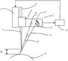
图1为激光加工自动调焦一种具体实施方式的结构示意图;Fig. 1 is a structural schematic diagram of a specific embodiment of automatic focusing in laser processing;
图2为加工激光焦点向下偏移时,检测激光束检测光线的反射光线夹角和聚焦成像在光线收集器的变化;Fig. 2 shows the change of the included angle of the reflected light of the detection laser beam and the focus image in the light collector when the focus of the processing laser is shifted downward;
图3为加工激光焦点向上偏移时,检测激光束检测光线的反射光线夹角和聚焦成像在光线收集器的变化。Fig. 3 shows the change of the included angle of the reflected light of the detection laser beam and the focused image in the light collector when the focus of the processing laser is shifted upward.
图4为激光加工自动调焦第二种具体实施方式的结构示意图;Fig. 4 is a structural schematic diagram of a second embodiment of laser processing automatic focusing;
图5为加工激光焦点向下偏移时,检测激光束检测光线的反射光线夹角和聚焦成像在光线收集器的变化的示意图;Fig. 5 is a schematic diagram of the change of the reflected light angle of the detection laser beam detection light and the change of the focused image in the light collector when the focus of the processing laser is shifted downward;
图6为加工激光焦点向上偏移时,检测激光束检测光线的反射光线夹角和聚焦成像在光线收集器的变化的示意图。Fig. 6 is a schematic diagram of the change of the included angle of the reflected light of the detection laser beam and the focused image in the light collector when the focus of the processing laser is shifted upward.
具体实施方式Detailed ways
下面通过附图和实例对本发明方法作进一步详细的说明。The method of the present invention will be described in further detail below by means of accompanying drawings and examples.
实现上述方法的装置之一,如图1所示,本发明装置包括Z轴移动系统1、激光聚焦系统3、激光位移检测系统7和控制系统9。As one of the devices for realizing the above method, as shown in FIG. 1 , the device of the present invention includes a Z-axis moving
激光位移检测系统7包括激光器10、透镜12和光线收集器11,透镜12和光线收集器11依次位于激光器10发射的激光束在工件表面上产生反射光的可视范围内。激光器10所发射的检测激光束5的功率以不破坏平面工件8为限,通常只有几瓦、几毫瓦甚至几个微瓦。The laser displacement detection system 7 includes a
激光位移检测系统7与激光聚焦系统3刚性连接在一起固定在Z轴移动系统1上,随Z轴移动系统1沿Z轴方向上下移动。加工激光束2经激光聚焦系统3聚焦后形成聚焦激光束4,并聚焦在被加工平面工件8的表面上。激光位移检测系统7中的激光器10对激光加工平面工件8发射一束检测激光束5,平面工件8的表面将检测激光束5以α0角度反射,形成激光束6反射回到激光位移检测系统7的接收端,穿过透镜12,聚焦成像在光线收集器11(由CCD或CMOS组成的光线收集器)的a处上形成光斑。设定聚焦激光束4聚焦在被加工平面工件8的表面时,激光位移检测系统7的检测激光束5反射回到接收端激光束6所产生角度和位置的输出信号为零,此时激光位移检测系统7对控制系统输出信号为零,控制系统9保持Z轴移动系统1不移动。The laser displacement detection system 7 is rigidly connected with the
实例1:Example 1:
当因某种原因使加工激光聚焦点4向下偏离工件8表面h1距离时(如图2所示),激光位移检测系统和工件表面之间的距离变短,反射激光线6与检测激光束5之间的夹角增加为α1,并穿过透镜12聚焦成像在光线收集器上的光斑位置从a处向下移动到e处。此时激光位移检测系统7将向控制系统9输出一定幅值的负电压或电流信号,幅值的大小与工激光聚焦点4的偏移距离大小呈线性比例。控制系统9根据激光位移检测系统7输入信号的符号和幅值大小调节Z轴移动系统1向上移动,激光位移检测系统和工件表面之间的距离也同时增加。当Z轴移动系统1向上移动相同的h1距离时,加工激光聚焦点4重新回到工件8表面上,反射激光线6与检测激光束5之间的夹角也重新回到α0,并穿过透镜12聚焦成像在光线收集器上的光斑位置从e处向上移动到a处,此时激光位移检测系统7对控制系统输出信号为零,控制系统9将停止Z轴移动系统1移动,完成激光自动调节过程。When the processing
实例2:Example 2:
当因某种原因使加工激光聚焦点4向上偏离工件8表面h2距离时(如图3所示),激光位移检测系统和工件表面之间的距离变长,反射激光线6与检测激光束5之间的夹角减小为α2,并穿过透镜12聚焦成像在光线收集器上的光斑位置从a处向下移动到f处,此时激光位移检测系统7将向控制系统9输出一定幅值的正电压或电流信号,幅值的大小与工激光聚焦点4的偏移距离大小呈线性比例。控制系统9根据激光位移检测系统7输入信号的符号和幅值大小调节Z轴移动系统1向下移动,激光位移检测系统和工件表面之间的距离也同时减小。当Z轴移动系统1向下移动相同的h2距离时,加工激光聚焦点4重新回到工件8表面上,反射激光线6与检测激光束5之间的夹角也重新回到α0,并穿过透镜12聚焦成像在光线收集器上的光斑位置从f处向上移动到a处,此时激光位移检测系统7对控制系统输出信号为零,控制系统9将停止Z轴移动系统1移动,完成激光自动调节过程。When the processing
实现上述方法的装置之二,如图4所示,用于激光曲面加工情况下的自动调焦方法及装置。由Z轴移动系统1、激光聚焦系统3、激光位移检测系统7和控制系统9组成。激光位移检测系统7与激光聚焦系统3刚性连接在一起固定在Z轴移动系统1上,随Z轴移动系统1沿Z轴方向上下移动。加工激光束2经激光聚焦系统3聚焦后形成聚焦激光束4,并聚焦在被加工曲面工件15的表面上。激光位移检测系统7中的激光器10对激光加工曲面工件15发射一束检测激光束5,与聚焦激光束4之间的夹角θ不大于40°,在激光加工曲面工件15上与聚焦激光束4焦点的空间位置重合,确保精确的测量激光焦点的偏移量。曲面工件15表面将检测激光束5以δ0角度反射,形成激光束6反射回到激光位移检测系统7的接收端,穿过透镜12,聚焦成像在光线收集器11(由CCD或CMOS组成的光线收集器)的a处上形成光斑。设定聚焦激光束4聚焦在被加工曲面工件15的表面时,激光位移检测系统7的检测激光束5反射回到接收端激光束6所产生角度和位置的输出信号为零,此时激光位移检测系统7对控制系统输出信号为零,控制系统9保持Z轴移动系统1不移动。The second device for realizing the above method, as shown in FIG. 4 , is used for an automatic focusing method and device in the case of laser curved surface processing. It consists of a Z-
实例3:Example 3:
当因某种原因使加工激光聚焦点4向下偏离曲面工件9表面h3距离时(如图5所示),激光位移检测系统和工件表面之间的距离变短,反射激光线6与检测激光束5之间的夹角增加为δ1,并穿过透镜12聚焦成像在光线收集器上的光斑位置从a处向下移动到d处。此时激光位移检测系统7将向控制系统9输出一定幅值的负电压或电流信号,幅值的大小与工激光聚焦点4的偏移距离大小呈线性比例。控制系统9根据激光位移检测系统7输入信号的符号和幅值大小调节Z轴移动系统1向上移动,激光位移检测系统和工件表面之间的距离也同时增加。当Z轴移动系统1向上移动相同的h3距离时,加工激光聚焦点4重新回到曲面工件15表面上,反射激光线6与检测激光束5之间的夹角也重新回到δ0,并穿过透镜12聚焦成像在光线收集器上的光斑位置从d处向上移动到a处,此时激光位移检测系统7对控制系统输出信号为零,控制系统9将停止Z轴移动系统1移动,完成激光自动调节过程。When the processing
实例4:Example 4:
当因某种原因使加工激光聚焦点4向上偏离曲面工件15表面h4距离时(如图6所示),激光位移检测系统和工件表面之间的距离变长,反射激光线6与检测激光束5之间的夹角减小为δ2,并穿过透镜12聚焦成像在光线收集器上的光斑位置从a处向下移动到g处,此时激光位移检测系统7将向控制系统9输出一定幅值的正电压或电流信号,幅值的大小与工激光聚焦点4的偏移距离大小呈线性比例。控制系统9根据激光位移检测系统7输入信号的符号和幅值大小调节Z轴移动系统1向下移动,激光位移检测系统和工件表面之间的距离也同时减小。当Z轴移动系统1向下移动相同的h2距离时,加工激光聚焦点4重新回到曲面工件15表面上,反射激光线6与检测激光束5之间的夹角也重新回到δ0,并穿过透镜12聚焦成像在光线收集器上的光斑位置从g处向上移动到a处,此时激光位移检测系统7对控制系统输出信号为零,控制系统9将停止Z轴移动系统1移动,完成激光自动调节过程。When the processing
本发明不仅局限于上述具体实施方式,本领域一般技术人员根据本发明公开的内容,可以采用其它多种具体实施方式实施本发明,因此,凡是采用本发明的技术方案和思路,做一些简单的变化或更改,都落入本发明保护的范围。The present invention is not limited to the above-mentioned specific embodiments, and those skilled in the art can adopt various other specific embodiments to implement the present invention according to the disclosed content of the present invention. Changes or modifications all fall within the protection scope of the present invention.
Claims (4)
Translated fromChinesePriority Applications (1)
| Application Number | Priority Date | Filing Date | Title |
|---|---|---|---|
| CN201110303415.2ACN102430858B (en) | 2011-10-10 | 2011-10-10 | Automatic focusing adjustor for laser processing |
Applications Claiming Priority (1)
| Application Number | Priority Date | Filing Date | Title |
|---|---|---|---|
| CN201110303415.2ACN102430858B (en) | 2011-10-10 | 2011-10-10 | Automatic focusing adjustor for laser processing |
Publications (2)
| Publication Number | Publication Date |
|---|---|
| CN102430858Atrue CN102430858A (en) | 2012-05-02 |
| CN102430858B CN102430858B (en) | 2014-10-29 |
Family
ID=45979399
Family Applications (1)
| Application Number | Title | Priority Date | Filing Date |
|---|---|---|---|
| CN201110303415.2AActiveCN102430858B (en) | 2011-10-10 | 2011-10-10 | Automatic focusing adjustor for laser processing |
Country Status (1)
| Country | Link |
|---|---|
| CN (1) | CN102430858B (en) |
Cited By (13)
| Publication number | Priority date | Publication date | Assignee | Title |
|---|---|---|---|---|
| CN103056517A (en)* | 2012-12-28 | 2013-04-24 | 江苏大学 | Three-dimensional laser washing device |
| CN103447687A (en)* | 2012-05-31 | 2013-12-18 | 灿美工程股份有限公司 | Laser processing system and method |
| CN103706945A (en)* | 2013-12-12 | 2014-04-09 | 武汉钢铁(集团)公司 | Method and device for correcting tool central point of industrial robot |
| CN106527053A (en)* | 2016-11-25 | 2017-03-22 | 天津津芯微电子科技有限公司 | LDI automatic focusing control method and system |
| CN107020450A (en)* | 2016-01-29 | 2017-08-08 | 发那科株式会社 | Laser machine |
| CN107627036A (en)* | 2017-10-12 | 2018-01-26 | 佛山汇众森泰科技有限公司 | Laser drill equipment is used in a kind of handicraft processing |
| CN107716468A (en)* | 2017-10-31 | 2018-02-23 | 广东工业大学 | A kind of laser auto focusing method, system, device and readable storage medium storing program for executing |
| CN109014567A (en)* | 2018-08-09 | 2018-12-18 | 厦门盈趣科技股份有限公司 | A kind of cost laser optimal process height adjuster and method |
| CN110967802A (en)* | 2018-09-30 | 2020-04-07 | 上海铁路通信有限公司 | High-power pulse laser self-adaptive zooming system |
| CN112008234A (en)* | 2020-09-07 | 2020-12-01 | 广州黑格智造信息科技有限公司 | Laser marking method and marking system for invisible appliance production |
| CN112222636A (en)* | 2020-10-12 | 2021-01-15 | 嘉兴奥锶特光电科技有限公司 | Laser cutting machine cutting head capable of automatically adjusting focus according to plate thickness |
| CN112705836A (en)* | 2021-03-26 | 2021-04-27 | 金洲数控(北京)软件技术有限公司 | Position follow-up method based on laser processing technology |
| CN113634877A (en)* | 2020-04-27 | 2021-11-12 | 大族激光科技产业集团股份有限公司 | Laser processing device and method |
Citations (15)
| Publication number | Priority date | Publication date | Assignee | Title |
|---|---|---|---|---|
| US3710798A (en)* | 1971-08-30 | 1973-01-16 | American Optical Corp | Laser system for microsurgery |
| US3892488A (en)* | 1974-02-22 | 1975-07-01 | Us Air Force | Laser site marking system |
| US4615621A (en)* | 1982-04-02 | 1986-10-07 | Eaton Corporation | Auto-focus alignment and measurement system and method |
| CN1966197A (en)* | 2005-11-18 | 2007-05-23 | 鸿富锦精密工业(深圳)有限公司 | Laser processing system and method |
| CN201002157Y (en)* | 2006-12-08 | 2008-01-09 | 华南理工大学 | Selective laser microbrazing system based on galvanometer scanning |
| CN101134266A (en)* | 2007-10-10 | 2008-03-05 | 厦门大学 | Multifunctional laser processing tool with measuring device |
| CN101171833A (en)* | 2005-05-11 | 2008-04-30 | 索尼爱立信移动通讯股份有限公司 | Digital camera with triangulation autofocus system and related method |
| CN101281289A (en)* | 2007-12-29 | 2008-10-08 | 青岛海信电器股份有限公司 | Automatic focusing method |
| CN101518855A (en)* | 2009-03-27 | 2009-09-02 | 华中科技大学 | Multifunctional laser processing device |
| CN101603811A (en)* | 2009-07-16 | 2009-12-16 | 天津大学 | Confocal type laser test head based on time difference method |
| CN101696881A (en)* | 2009-07-03 | 2010-04-21 | 深圳市凯意科技有限公司 | Focusing system in triangulation |
| CN101893426A (en)* | 2010-07-02 | 2010-11-24 | 西安交通大学 | A method for on-line detection and control of laser metal forming height |
| CN102059589A (en)* | 2010-10-21 | 2011-05-18 | 大连理工大学 | Device and method for detecting inclination angle error of laser displacement sensor |
| CN102141738A (en)* | 2011-04-02 | 2011-08-03 | 中国科学院光电技术研究所 | A Nanoscale Automatic Focusing System for Projection Lithography |
| CN202317434U (en)* | 2011-10-10 | 2012-07-11 | 华中科技大学 | Laser processing automatic focusing adjustment device |
- 2011
- 2011-10-10CNCN201110303415.2Apatent/CN102430858B/enactiveActive
Patent Citations (15)
| Publication number | Priority date | Publication date | Assignee | Title |
|---|---|---|---|---|
| US3710798A (en)* | 1971-08-30 | 1973-01-16 | American Optical Corp | Laser system for microsurgery |
| US3892488A (en)* | 1974-02-22 | 1975-07-01 | Us Air Force | Laser site marking system |
| US4615621A (en)* | 1982-04-02 | 1986-10-07 | Eaton Corporation | Auto-focus alignment and measurement system and method |
| CN101171833A (en)* | 2005-05-11 | 2008-04-30 | 索尼爱立信移动通讯股份有限公司 | Digital camera with triangulation autofocus system and related method |
| CN1966197A (en)* | 2005-11-18 | 2007-05-23 | 鸿富锦精密工业(深圳)有限公司 | Laser processing system and method |
| CN201002157Y (en)* | 2006-12-08 | 2008-01-09 | 华南理工大学 | Selective laser microbrazing system based on galvanometer scanning |
| CN101134266A (en)* | 2007-10-10 | 2008-03-05 | 厦门大学 | Multifunctional laser processing tool with measuring device |
| CN101281289A (en)* | 2007-12-29 | 2008-10-08 | 青岛海信电器股份有限公司 | Automatic focusing method |
| CN101518855A (en)* | 2009-03-27 | 2009-09-02 | 华中科技大学 | Multifunctional laser processing device |
| CN101696881A (en)* | 2009-07-03 | 2010-04-21 | 深圳市凯意科技有限公司 | Focusing system in triangulation |
| CN101603811A (en)* | 2009-07-16 | 2009-12-16 | 天津大学 | Confocal type laser test head based on time difference method |
| CN101893426A (en)* | 2010-07-02 | 2010-11-24 | 西安交通大学 | A method for on-line detection and control of laser metal forming height |
| CN102059589A (en)* | 2010-10-21 | 2011-05-18 | 大连理工大学 | Device and method for detecting inclination angle error of laser displacement sensor |
| CN102141738A (en)* | 2011-04-02 | 2011-08-03 | 中国科学院光电技术研究所 | A Nanoscale Automatic Focusing System for Projection Lithography |
| CN202317434U (en)* | 2011-10-10 | 2012-07-11 | 华中科技大学 | Laser processing automatic focusing adjustment device |
Cited By (17)
| Publication number | Priority date | Publication date | Assignee | Title |
|---|---|---|---|---|
| CN103447687A (en)* | 2012-05-31 | 2013-12-18 | 灿美工程股份有限公司 | Laser processing system and method |
| CN103056517A (en)* | 2012-12-28 | 2013-04-24 | 江苏大学 | Three-dimensional laser washing device |
| CN103706945A (en)* | 2013-12-12 | 2014-04-09 | 武汉钢铁(集团)公司 | Method and device for correcting tool central point of industrial robot |
| CN103706945B (en)* | 2013-12-12 | 2016-02-10 | 武汉钢铁(集团)公司 | A kind of bearing calibration of tool central point of industrial robot and device |
| US10928615B2 (en) | 2016-01-29 | 2021-02-23 | Fanuc Corporation | Laser processing device having approach function of processing head |
| CN107020450A (en)* | 2016-01-29 | 2017-08-08 | 发那科株式会社 | Laser machine |
| CN107020450B (en)* | 2016-01-29 | 2019-10-15 | 发那科株式会社 | Laser machine |
| CN106527053A (en)* | 2016-11-25 | 2017-03-22 | 天津津芯微电子科技有限公司 | LDI automatic focusing control method and system |
| CN107627036A (en)* | 2017-10-12 | 2018-01-26 | 佛山汇众森泰科技有限公司 | Laser drill equipment is used in a kind of handicraft processing |
| CN107716468A (en)* | 2017-10-31 | 2018-02-23 | 广东工业大学 | A kind of laser auto focusing method, system, device and readable storage medium storing program for executing |
| CN109014567A (en)* | 2018-08-09 | 2018-12-18 | 厦门盈趣科技股份有限公司 | A kind of cost laser optimal process height adjuster and method |
| CN109014567B (en)* | 2018-08-09 | 2023-09-12 | 厦门盈趣科技股份有限公司 | Low-cost laser optimal machining height adjusting device and method |
| CN110967802A (en)* | 2018-09-30 | 2020-04-07 | 上海铁路通信有限公司 | High-power pulse laser self-adaptive zooming system |
| CN113634877A (en)* | 2020-04-27 | 2021-11-12 | 大族激光科技产业集团股份有限公司 | Laser processing device and method |
| CN112008234A (en)* | 2020-09-07 | 2020-12-01 | 广州黑格智造信息科技有限公司 | Laser marking method and marking system for invisible appliance production |
| CN112222636A (en)* | 2020-10-12 | 2021-01-15 | 嘉兴奥锶特光电科技有限公司 | Laser cutting machine cutting head capable of automatically adjusting focus according to plate thickness |
| CN112705836A (en)* | 2021-03-26 | 2021-04-27 | 金洲数控(北京)软件技术有限公司 | Position follow-up method based on laser processing technology |
Also Published As
| Publication number | Publication date |
|---|---|
| CN102430858B (en) | 2014-10-29 |
Similar Documents
| Publication | Publication Date | Title |
|---|---|---|
| CN102430858A (en) | Automatic focusing adjustor for laser processing | |
| CN202317434U (en) | Laser processing automatic focusing adjustment device | |
| CN101244523B (en) | Laser processing detection method and its special equipment | |
| JP5584140B2 (en) | Non-contact surface shape measuring method and apparatus | |
| CN101518855B (en) | A multifunctional laser processing equipment | |
| CN105799176B (en) | laser output device and 3D printer | |
| JP3918583B2 (en) | High density energy processing apparatus and high density energy processing method | |
| CN110142503A (en) | A laser cutting defocus compensation system and its compensation method | |
| CN107941154B (en) | Displacement measurement system and measurement method | |
| CN110524109A (en) | A scanning galvanometer laser welding system | |
| JP2005329436A (en) | Laser machining method | |
| CN100534697C (en) | Laser micro processor optical focus system | |
| CN104913734A (en) | Galvanometric line laser scanning 3D profile measurement device and method | |
| CN102658431B (en) | Device for automatically diagnosing and correcting divergence angle and beam quality of laser beam | |
| CN203712074U (en) | High-accuracy double-sensor laser scanning galvanometer system and scanning galvanometer motor thereof | |
| CN119343028A (en) | A method and device for high-precision laser selective etching of curved surface multilayer film system | |
| Franz et al. | Evaluation of an ultrashort pulsed laser robot system for flexible and large-area micromachining | |
| Guo et al. | A novel multifunctional visual sensor based on combined laser structured lights and its anti-jamming detection algorithms | |
| JP2000084689A (en) | Laser beam machining device | |
| CN207205562U (en) | A kind of laser welding defocus amount determining device | |
| CN111843190B (en) | Calibration method for laser processing equipment | |
| CN118180646A (en) | Automatic focusing system and implementation method thereof | |
| KR102796363B1 (en) | Laser displacement sensor and design method thereof | |
| CN110657748A (en) | Laser displacement sensor with automatic focusing function | |
| TWI496643B (en) | Three-dimensional processing device |
Legal Events
| Date | Code | Title | Description |
|---|---|---|---|
| C06 | Publication | ||
| PB01 | Publication | ||
| C10 | Entry into substantive examination | ||
| SE01 | Entry into force of request for substantive examination | ||
| C14 | Grant of patent or utility model | ||
| GR01 | Patent grant | ||
| TR01 | Transfer of patent right | Effective date of registration:20180307 Address after:436070 Ezhou city Gedian Development Zone No. 1 Industrial Zone entrepreneurship service center in Hubei Patentee after:Wuhan flex Laser Technology Co., Ltd. Address before:430074 Hubei Province, Wuhan city Hongshan District Luoyu Road No. 1037 Patentee before:Huazhong University of Science and Technology | |
| TR01 | Transfer of patent right |